EP0955084B1 - Method of depositing an array of biological samples using a redrawn capillary reservoir - Google Patents
Method of depositing an array of biological samples using a redrawn capillary reservoirDownload PDFInfo
- Publication number
- EP0955084B1 EP0955084B1EP98401021AEP98401021AEP0955084B1EP 0955084 B1EP0955084 B1EP 0955084B1EP 98401021 AEP98401021 AEP 98401021AEP 98401021 AEP98401021 AEP 98401021AEP 0955084 B1EP0955084 B1EP 0955084B1
- Authority
- EP
- European Patent Office
- Prior art keywords
- substrate
- array
- channel
- channels
- liquid
- Prior art date
- Legal status (The legal status is an assumption and is not a legal conclusion. Google has not performed a legal analysis and makes no representation as to the accuracy of the status listed.)
- Expired - Lifetime
Links
- 238000000034methodMethods0.000titleclaimsdescription49
- 238000000151depositionMethods0.000titleclaimsdescription8
- 239000012472biological sampleSubstances0.000titleclaimsdescription5
- 239000000758substrateSubstances0.000claimsdescription32
- 239000011521glassSubstances0.000claimsdescription24
- 239000007788liquidSubstances0.000claimsdescription23
- 108091034117OligonucleotideProteins0.000claimsdescription16
- 230000027455bindingEffects0.000claimsdescription13
- 239000000463materialSubstances0.000claimsdescription11
- 230000007423decreaseEffects0.000claimsdescription6
- 229920001169thermoplasticPolymers0.000claimsdescription5
- 238000011049fillingMethods0.000claimsdescription3
- 230000008014freezingEffects0.000claimsdescription2
- 238000007710freezingMethods0.000claimsdescription2
- 238000009736wettingMethods0.000description25
- 238000001125extrusionMethods0.000description12
- 229920000642polymerPolymers0.000description12
- 239000000203mixtureSubstances0.000description11
- -1polypropylenePolymers0.000description11
- 230000008569processEffects0.000description11
- JLCPHMBAVCMARE-UHFFFAOYSA-N[3-[[3-[[3-[[3-[[3-[[3-[[3-[[3-[[3-[[3-[[3-[[5-(2-amino-6-oxo-1H-purin-9-yl)-3-[[3-[[3-[[3-[[3-[[3-[[5-(2-amino-6-oxo-1H-purin-9-yl)-3-[[5-(2-amino-6-oxo-1H-purin-9-yl)-3-hydroxyoxolan-2-yl]methoxy-hydroxyphosphoryl]oxyoxolan-2-yl]methoxy-hydroxyphosphoryl]oxy-5-(5-methyl-2,4-dioxopyrimidin-1-yl)oxolan-2-yl]methoxy-hydroxyphosphoryl]oxy-5-(6-aminopurin-9-yl)oxolan-2-yl]methoxy-hydroxyphosphoryl]oxy-5-(6-aminopurin-9-yl)oxolan-2-yl]methoxy-hydroxyphosphoryl]oxy-5-(6-aminopurin-9-yl)oxolan-2-yl]methoxy-hydroxyphosphoryl]oxy-5-(6-aminopurin-9-yl)oxolan-2-yl]methoxy-hydroxyphosphoryl]oxyoxolan-2-yl]methoxy-hydroxyphosphoryl]oxy-5-(5-methyl-2,4-dioxopyrimidin-1-yl)oxolan-2-yl]methoxy-hydroxyphosphoryl]oxy-5-(4-amino-2-oxopyrimidin-1-yl)oxolan-2-yl]methoxy-hydroxyphosphoryl]oxy-5-(5-methyl-2,4-dioxopyrimidin-1-yl)oxolan-2-yl]methoxy-hydroxyphosphoryl]oxy-5-(5-methyl-2,4-dioxopyrimidin-1-yl)oxolan-2-yl]methoxy-hydroxyphosphoryl]oxy-5-(6-aminopurin-9-yl)oxolan-2-yl]methoxy-hydroxyphosphoryl]oxy-5-(6-aminopurin-9-yl)oxolan-2-yl]methoxy-hydroxyphosphoryl]oxy-5-(4-amino-2-oxopyrimidin-1-yl)oxolan-2-yl]methoxy-hydroxyphosphoryl]oxy-5-(4-amino-2-oxopyrimidin-1-yl)oxolan-2-yl]methoxy-hydroxyphosphoryl]oxy-5-(4-amino-2-oxopyrimidin-1-yl)oxolan-2-yl]methoxy-hydroxyphosphoryl]oxy-5-(6-aminopurin-9-yl)oxolan-2-yl]methoxy-hydroxyphosphoryl]oxy-5-(4-amino-2-oxopyrimidin-1-yl)oxolan-2-yl]methyl [5-(6-aminopurin-9-yl)-2-(hydroxymethyl)oxolan-3-yl] hydrogen phosphatePolymersCc1cn(C2CC(OP(O)(=O)OCC3OC(CC3OP(O)(=O)OCC3OC(CC3O)n3cnc4c3nc(N)[nH]c4=O)n3cnc4c3nc(N)[nH]c4=O)C(COP(O)(=O)OC3CC(OC3COP(O)(=O)OC3CC(OC3COP(O)(=O)OC3CC(OC3COP(O)(=O)OC3CC(OC3COP(O)(=O)OC3CC(OC3COP(O)(=O)OC3CC(OC3COP(O)(=O)OC3CC(OC3COP(O)(=O)OC3CC(OC3COP(O)(=O)OC3CC(OC3COP(O)(=O)OC3CC(OC3COP(O)(=O)OC3CC(OC3COP(O)(=O)OC3CC(OC3COP(O)(=O)OC3CC(OC3COP(O)(=O)OC3CC(OC3COP(O)(=O)OC3CC(OC3COP(O)(=O)OC3CC(OC3COP(O)(=O)OC3CC(OC3CO)n3cnc4c(N)ncnc34)n3ccc(N)nc3=O)n3cnc4c(N)ncnc34)n3ccc(N)nc3=O)n3ccc(N)nc3=O)n3ccc(N)nc3=O)n3cnc4c(N)ncnc34)n3cnc4c(N)ncnc34)n3cc(C)c(=O)[nH]c3=O)n3cc(C)c(=O)[nH]c3=O)n3ccc(N)nc3=O)n3cc(C)c(=O)[nH]c3=O)n3cnc4c3nc(N)[nH]c4=O)n3cnc4c(N)ncnc34)n3cnc4c(N)ncnc34)n3cnc4c(N)ncnc34)n3cnc4c(N)ncnc34)O2)c(=O)[nH]c1=OJLCPHMBAVCMARE-UHFFFAOYSA-N0.000description9
- 239000011230binding agentSubstances0.000description9
- 239000011159matrix materialSubstances0.000description8
- 239000000843powderSubstances0.000description8
- 238000009396hybridizationMethods0.000description7
- 238000005245sinteringMethods0.000description7
- RZVAJINKPMORJF-UHFFFAOYSA-NAcetaminophenChemical compoundCC(=O)NC1=CC=C(O)C=C1RZVAJINKPMORJF-UHFFFAOYSA-N0.000description6
- HRPVXLWXLXDGHG-UHFFFAOYSA-NAcrylamideChemical compoundNC(=O)C=CHRPVXLWXLXDGHG-UHFFFAOYSA-N0.000description6
- 108020004707nucleic acidsProteins0.000description6
- 102000039446nucleic acidsHuman genes0.000description6
- 150000007523nucleic acidsChemical class0.000description6
- 239000005297pyrexSubstances0.000description6
- XLYOFNOQVPJJNP-UHFFFAOYSA-NwaterSubstancesOXLYOFNOQVPJJNP-UHFFFAOYSA-N0.000description6
- 239000004743PolypropyleneSubstances0.000description5
- 239000003822epoxy resinSubstances0.000description5
- 239000012530fluidSubstances0.000description5
- 229920000647polyepoxidePolymers0.000description5
- 229920001155polypropylenePolymers0.000description5
- 239000001993waxSubstances0.000description5
- 238000004458analytical methodMethods0.000description4
- 238000003491arrayMethods0.000description4
- 239000011324beadSubstances0.000description4
- 238000005520cutting processMethods0.000description4
- 239000012634fragmentSubstances0.000description4
- 238000010438heat treatmentMethods0.000description4
- 238000011068loading methodMethods0.000description4
- 229920000620organic polymerPolymers0.000description4
- 239000002245particleSubstances0.000description4
- 230000009467reductionEffects0.000description4
- 239000000523sampleSubstances0.000description4
- 239000000243solutionSubstances0.000description4
- 108020004414DNAProteins0.000description3
- 102000053602DNAHuman genes0.000description3
- 238000000137annealingMethods0.000description3
- 230000001413cellular effectEffects0.000description3
- 239000003153chemical reaction reagentSubstances0.000description3
- 239000011248coating agentSubstances0.000description3
- 238000000576coating methodMethods0.000description3
- 239000002299complementary DNASubstances0.000description3
- 230000008021depositionEffects0.000description3
- 238000001962electrophoresisMethods0.000description3
- 238000007641inkjet printingMethods0.000description3
- 238000004519manufacturing processMethods0.000description3
- 239000002773nucleotideSubstances0.000description3
- 125000003729nucleotide groupChemical group0.000description3
- 238000002966oligonucleotide arrayMethods0.000description3
- 230000001590oxidative effectEffects0.000description3
- 239000004033plasticSubstances0.000description3
- 229920003023plasticPolymers0.000description3
- 239000007787solidSubstances0.000description3
- 239000000126substanceSubstances0.000description3
- WRIDQFICGBMAFQ-UHFFFAOYSA-N(E)-8-Octadecenoic acidNatural productsCCCCCCCCCC=CCCCCCCC(O)=OWRIDQFICGBMAFQ-UHFFFAOYSA-N0.000description2
- LQJBNNIYVWPHFW-UHFFFAOYSA-N20:1omega9c fatty acidNatural productsCCCCCCCCCCC=CCCCCCCCC(O)=OLQJBNNIYVWPHFW-UHFFFAOYSA-N0.000description2
- QSBYPNXLFMSGKH-UHFFFAOYSA-N9-HeptadecensaeureNatural productsCCCCCCCC=CCCCCCCCC(O)=OQSBYPNXLFMSGKH-UHFFFAOYSA-N0.000description2
- 239000004593EpoxySubstances0.000description2
- 208000026350Inborn Genetic diseaseDiseases0.000description2
- 229920003091Methocel™Polymers0.000description2
- ZQPPMHVWECSIRJ-UHFFFAOYSA-NOleic acidNatural productsCCCCCCCCC=CCCCCCCCC(O)=OZQPPMHVWECSIRJ-UHFFFAOYSA-N0.000description2
- 239000005642Oleic acidSubstances0.000description2
- 108020005187Oligonucleotide ProbesProteins0.000description2
- 239000004793PolystyreneSubstances0.000description2
- BLRPTPMANUNPDV-UHFFFAOYSA-NSilaneChemical compound[SiH4]BLRPTPMANUNPDV-UHFFFAOYSA-N0.000description2
- VYPSYNLAJGMNEJ-UHFFFAOYSA-NSilicium dioxideChemical compoundO=[Si]=OVYPSYNLAJGMNEJ-UHFFFAOYSA-N0.000description2
- MCMNRKCIXSYSNV-UHFFFAOYSA-NZirconium dioxideChemical compoundO=[Zr]=OMCMNRKCIXSYSNV-UHFFFAOYSA-N0.000description2
- PNEYBMLMFCGWSK-UHFFFAOYSA-Naluminium oxideInorganic materials[O-2].[O-2].[O-2].[Al+3].[Al+3]PNEYBMLMFCGWSK-UHFFFAOYSA-N0.000description2
- 238000013459approachMethods0.000description2
- 239000000919ceramicSubstances0.000description2
- 230000000295complement effectEffects0.000description2
- 239000002131composite materialSubstances0.000description2
- 150000001875compoundsChemical class0.000description2
- 238000005859coupling reactionMethods0.000description2
- 238000002405diagnostic procedureMethods0.000description2
- 229910003460diamondInorganic materials0.000description2
- 239000010432diamondSubstances0.000description2
- 239000004205dimethyl polysiloxaneSubstances0.000description2
- 208000016361genetic diseaseDiseases0.000description2
- 239000002241glass-ceramicSubstances0.000description2
- QXJSBBXBKPUZAA-UHFFFAOYSA-Nisooleic acidNatural productsCCCCCCCC=CCCCCCCCCC(O)=OQXJSBBXBKPUZAA-UHFFFAOYSA-N0.000description2
- 239000003446ligandSubstances0.000description2
- 230000008018meltingEffects0.000description2
- 238000002844meltingMethods0.000description2
- 239000012528membraneSubstances0.000description2
- ZQPPMHVWECSIRJ-KTKRTIGZSA-Noleic acidChemical compoundCCCCCCCC\C=C/CCCCCCCC(O)=OZQPPMHVWECSIRJ-KTKRTIGZSA-N0.000description2
- 239000002751oligonucleotide probeSubstances0.000description2
- 244000052769pathogenSpecies0.000description2
- 238000005498polishingMethods0.000description2
- 229920000435poly(dimethylsiloxane)Polymers0.000description2
- 229920000098polyolefinPolymers0.000description2
- 229920002223polystyrenePolymers0.000description2
- 108090000623proteins and genesProteins0.000description2
- 230000005855radiationEffects0.000description2
- 229920002477rna polymerPolymers0.000description2
- 238000007665saggingMethods0.000description2
- 238000012163sequencing techniqueMethods0.000description2
- 229910000077silaneInorganic materials0.000description2
- 241000894007speciesSpecies0.000description2
- 230000009870specific bindingEffects0.000description2
- 239000000725suspensionSubstances0.000description2
- 238000003786synthesis reactionMethods0.000description2
- 239000012815thermoplastic materialSubstances0.000description2
- YCFBPCFPRWYZFG-UHFFFAOYSA-Ntrichloro(10-fluorodecyl)silaneChemical compoundFCCCCCCCCCC[Si](Cl)(Cl)ClYCFBPCFPRWYZFG-UHFFFAOYSA-N0.000description2
- FZMJEGJVKFTGMU-UHFFFAOYSA-Ntriethoxy(octadecyl)silaneChemical compoundCCCCCCCCCCCCCCCCCC[Si](OCC)(OCC)OCCFZMJEGJVKFTGMU-UHFFFAOYSA-N0.000description2
- WYTZZXDRDKSJID-UHFFFAOYSA-N(3-aminopropyl)triethoxysilaneChemical compoundCCO[Si](OCC)(OCC)CCCNWYTZZXDRDKSJID-UHFFFAOYSA-N0.000description1
- URDOJQUSEUXVRP-UHFFFAOYSA-N3-triethoxysilylpropyl 2-methylprop-2-enoateChemical compoundCCO[Si](OCC)(OCC)CCCOC(=O)C(C)=CURDOJQUSEUXVRP-UHFFFAOYSA-N0.000description1
- 240000008100Brassica rapaSpecies0.000description1
- 239000004215Carbon black (E152)Substances0.000description1
- 206010071602Genetic polymorphismDiseases0.000description1
- 108090001090LectinsProteins0.000description1
- 102000004856LectinsHuman genes0.000description1
- 206010028980NeoplasmDiseases0.000description1
- 239000004698PolyethyleneSubstances0.000description1
- 230000003213activating effectEffects0.000description1
- 230000004913activationEffects0.000description1
- 238000004026adhesive bondingMethods0.000description1
- 150000001412aminesChemical class0.000description1
- 150000001413amino acidsChemical class0.000description1
- 238000000429assemblyMethods0.000description1
- 230000000712assemblyEffects0.000description1
- 238000005452bendingMethods0.000description1
- 230000008901benefitEffects0.000description1
- 239000012620biological materialSubstances0.000description1
- 230000015572biosynthetic processEffects0.000description1
- 201000011510cancerDiseases0.000description1
- 229910010293ceramic materialInorganic materials0.000description1
- 125000003636chemical groupChemical group0.000description1
- 238000006243chemical reactionMethods0.000description1
- 239000003795chemical substances by applicationSubstances0.000description1
- KRVSOGSZCMJSLX-UHFFFAOYSA-Lchromic acidChemical classO[Cr](O)(=O)=OKRVSOGSZCMJSLX-UHFFFAOYSA-L0.000description1
- 238000010367cloningMethods0.000description1
- 229910052681coesiteInorganic materials0.000description1
- 238000007398colorimetric assayMethods0.000description1
- 239000000470constituentSubstances0.000description1
- 238000011109contaminationMethods0.000description1
- 238000007796conventional methodMethods0.000description1
- 230000008878couplingEffects0.000description1
- 238000010168coupling processMethods0.000description1
- 229910052906cristobaliteInorganic materials0.000description1
- 229920006037cross link polymerPolymers0.000description1
- 238000004132cross linkingMethods0.000description1
- 239000006063culletSubstances0.000description1
- 230000000994depressogenic effectEffects0.000description1
- 238000013461designMethods0.000description1
- 238000001514detection methodMethods0.000description1
- 238000003745diagnosisMethods0.000description1
- 238000007598dipping methodMethods0.000description1
- 230000000694effectsEffects0.000description1
- 230000008030eliminationEffects0.000description1
- 238000003379elimination reactionMethods0.000description1
- 239000000839emulsionSubstances0.000description1
- 238000005516engineering processMethods0.000description1
- 125000003700epoxy groupChemical group0.000description1
- 239000000835fiberSubstances0.000description1
- 239000012467final productSubstances0.000description1
- 238000010304firingMethods0.000description1
- 239000005357flat glassSubstances0.000description1
- 239000007850fluorescent dyeSubstances0.000description1
- 230000004907fluxEffects0.000description1
- 125000002485formyl groupChemical class[H]C(*)=O0.000description1
- 230000004927fusionEffects0.000description1
- 239000000499gelSubstances0.000description1
- 102000054767gene variantHuman genes0.000description1
- 239000006112glass ceramic compositionSubstances0.000description1
- 230000009477glass transitionEffects0.000description1
- 150000004676glycansChemical class0.000description1
- 229930195733hydrocarbonNatural products0.000description1
- 150000002430hydrocarbonsChemical class0.000description1
- 239000004615ingredientSubstances0.000description1
- 238000001746injection mouldingMethods0.000description1
- 230000003993interactionEffects0.000description1
- 239000002523lectinSubstances0.000description1
- 239000006194liquid suspensionSubstances0.000description1
- 229920002521macromoleculePolymers0.000description1
- 238000013507mappingMethods0.000description1
- 230000000873masking effectEffects0.000description1
- 230000007246mechanismEffects0.000description1
- 238000002493microarrayMethods0.000description1
- 244000000010microbial pathogenSpecies0.000description1
- 230000004048modificationEffects0.000description1
- 238000012986modificationMethods0.000description1
- 230000035772mutationEffects0.000description1
- 239000002086nanomaterialSubstances0.000description1
- 239000002777nucleosideSubstances0.000description1
- 125000003835nucleoside groupChemical group0.000description1
- 238000002515oligonucleotide synthesisMethods0.000description1
- 230000003287optical effectEffects0.000description1
- 150000001282organosilanesChemical class0.000description1
- 239000012188paraffin waxSubstances0.000description1
- 230000035515penetrationEffects0.000description1
- 229920002120photoresistant polymerPolymers0.000description1
- 229920000573polyethylenePolymers0.000description1
- 238000006116polymerization reactionMethods0.000description1
- 229920001282polysaccharidePolymers0.000description1
- 239000005017polysaccharideSubstances0.000description1
- 239000012254powdered materialSubstances0.000description1
- 239000002244precipitateSubstances0.000description1
- 150000003141primary aminesChemical class0.000description1
- 238000007639printingMethods0.000description1
- 102000004196processed proteins & peptidesHuman genes0.000description1
- 108090000765processed proteins & peptidesProteins0.000description1
- 102000004169proteins and genesHuman genes0.000description1
- 238000000746purificationMethods0.000description1
- 238000000197pyrolysisMethods0.000description1
- 230000002285radioactive effectEffects0.000description1
- 238000011160researchMethods0.000description1
- 229920005989resinPolymers0.000description1
- 239000011347resinSubstances0.000description1
- 230000000717retained effectEffects0.000description1
- 238000000518rheometryMethods0.000description1
- 238000005096rolling processMethods0.000description1
- 238000010079rubber tappingMethods0.000description1
- 238000012216screeningMethods0.000description1
- 238000000926separation methodMethods0.000description1
- 239000000377silicon dioxideSubstances0.000description1
- 239000002002slurrySubstances0.000description1
- 239000007790solid phaseSubstances0.000description1
- 238000007711solidificationMethods0.000description1
- 230000008023solidificationEffects0.000description1
- 239000002904solventSubstances0.000description1
- 229910052682stishoviteInorganic materials0.000description1
- 230000002194synthesizing effectEffects0.000description1
- 229920001059synthetic polymerPolymers0.000description1
- 230000008646thermal stressEffects0.000description1
- 239000004416thermosoftening plasticSubstances0.000description1
- 125000003396thiol groupChemical group[H]S*0.000description1
- 238000003325tomographyMethods0.000description1
- 230000009466transformationEffects0.000description1
- 230000007704transitionEffects0.000description1
- 238000011282treatmentMethods0.000description1
- 229910052905tridymiteInorganic materials0.000description1
- 244000052613viral pathogenSpecies0.000description1
- 230000003612virological effectEffects0.000description1
- 238000005406washingMethods0.000description1
- 238000003466weldingMethods0.000description1
- 239000000080wetting agentSubstances0.000description1
Images


Classifications
- B—PERFORMING OPERATIONS; TRANSPORTING
- B01—PHYSICAL OR CHEMICAL PROCESSES OR APPARATUS IN GENERAL
- B01J—CHEMICAL OR PHYSICAL PROCESSES, e.g. CATALYSIS OR COLLOID CHEMISTRY; THEIR RELEVANT APPARATUS
- B01J19/00—Chemical, physical or physico-chemical processes in general; Their relevant apparatus
- B01J19/0046—Sequential or parallel reactions, e.g. for the synthesis of polypeptides or polynucleotides; Apparatus and devices for combinatorial chemistry or for making molecular arrays
- B—PERFORMING OPERATIONS; TRANSPORTING
- B01—PHYSICAL OR CHEMICAL PROCESSES OR APPARATUS IN GENERAL
- B01L—CHEMICAL OR PHYSICAL LABORATORY APPARATUS FOR GENERAL USE
- B01L3/00—Containers or dishes for laboratory use, e.g. laboratory glassware; Droppers
- B01L3/02—Burettes; Pipettes
- B—PERFORMING OPERATIONS; TRANSPORTING
- B01—PHYSICAL OR CHEMICAL PROCESSES OR APPARATUS IN GENERAL
- B01J—CHEMICAL OR PHYSICAL PROCESSES, e.g. CATALYSIS OR COLLOID CHEMISTRY; THEIR RELEVANT APPARATUS
- B01J4/00—Feed or outlet devices; Feed or outlet control devices
- B01J4/02—Feed or outlet devices; Feed or outlet control devices for feeding measured, i.e. prescribed quantities of reagents
- B—PERFORMING OPERATIONS; TRANSPORTING
- B01—PHYSICAL OR CHEMICAL PROCESSES OR APPARATUS IN GENERAL
- B01L—CHEMICAL OR PHYSICAL LABORATORY APPARATUS FOR GENERAL USE
- B01L3/00—Containers or dishes for laboratory use, e.g. laboratory glassware; Droppers
- B01L3/02—Burettes; Pipettes
- B01L3/0241—Drop counters; Drop formers
- B01L3/0244—Drop counters; Drop formers using pins
- B—PERFORMING OPERATIONS; TRANSPORTING
- B01—PHYSICAL OR CHEMICAL PROCESSES OR APPARATUS IN GENERAL
- B01L—CHEMICAL OR PHYSICAL LABORATORY APPARATUS FOR GENERAL USE
- B01L3/00—Containers or dishes for laboratory use, e.g. laboratory glassware; Droppers
- B01L3/02—Burettes; Pipettes
- B01L3/0241—Drop counters; Drop formers
- B01L3/0262—Drop counters; Drop formers using touch-off at substrate or container
- B—PERFORMING OPERATIONS; TRANSPORTING
- B01—PHYSICAL OR CHEMICAL PROCESSES OR APPARATUS IN GENERAL
- B01L—CHEMICAL OR PHYSICAL LABORATORY APPARATUS FOR GENERAL USE
- B01L3/00—Containers or dishes for laboratory use, e.g. laboratory glassware; Droppers
- B01L3/50—Containers for the purpose of retaining a material to be analysed, e.g. test tubes
- B01L3/508—Containers for the purpose of retaining a material to be analysed, e.g. test tubes rigid containers not provided for above
- B01L3/5085—Containers for the purpose of retaining a material to be analysed, e.g. test tubes rigid containers not provided for above for multiple samples, e.g. microtitration plates
- B01L3/50857—Containers for the purpose of retaining a material to be analysed, e.g. test tubes rigid containers not provided for above for multiple samples, e.g. microtitration plates using arrays or bundles of open capillaries for holding samples
- B—PERFORMING OPERATIONS; TRANSPORTING
- B01—PHYSICAL OR CHEMICAL PROCESSES OR APPARATUS IN GENERAL
- B01L—CHEMICAL OR PHYSICAL LABORATORY APPARATUS FOR GENERAL USE
- B01L3/00—Containers or dishes for laboratory use, e.g. laboratory glassware; Droppers
- B01L3/56—Labware specially adapted for transferring fluids
- B01L3/563—Joints or fittings ; Separable fluid transfer means to transfer fluids between at least two containers, e.g. connectors
- C—CHEMISTRY; METALLURGY
- C03—GLASS; MINERAL OR SLAG WOOL
- C03B—MANUFACTURE, SHAPING, OR SUPPLEMENTARY PROCESSES
- C03B19/00—Other methods of shaping glass
- C03B19/06—Other methods of shaping glass by sintering, e.g. by cold isostatic pressing of powders and subsequent sintering, by hot pressing of powders, by sintering slurries or dispersions not undergoing a liquid phase reaction
- C—CHEMISTRY; METALLURGY
- C03—GLASS; MINERAL OR SLAG WOOL
- C03B—MANUFACTURE, SHAPING, OR SUPPLEMENTARY PROCESSES
- C03B23/00—Re-forming shaped glass
- C03B23/04—Re-forming tubes or rods
- C03B23/047—Re-forming tubes or rods by drawing
- C—CHEMISTRY; METALLURGY
- C03—GLASS; MINERAL OR SLAG WOOL
- C03B—MANUFACTURE, SHAPING, OR SUPPLEMENTARY PROCESSES
- C03B23/00—Re-forming shaped glass
- C03B23/04—Re-forming tubes or rods
- C03B23/06—Re-forming tubes or rods by bending
- C—CHEMISTRY; METALLURGY
- C03—GLASS; MINERAL OR SLAG WOOL
- C03B—MANUFACTURE, SHAPING, OR SUPPLEMENTARY PROCESSES
- C03B37/00—Manufacture or treatment of flakes, fibres, or filaments from softened glass, minerals, or slags
- C03B37/01—Manufacture of glass fibres or filaments
- C03B37/02—Manufacture of glass fibres or filaments by drawing or extruding, e.g. direct drawing of molten glass from nozzles; Cooling fins therefor
- C03B37/025—Manufacture of glass fibres or filaments by drawing or extruding, e.g. direct drawing of molten glass from nozzles; Cooling fins therefor from reheated softened tubes, rods, fibres or filaments, e.g. drawing fibres from preforms
- C03B37/028—Drawing fibre bundles, e.g. for making fibre bundles of multifibres, image fibres
- G—PHYSICS
- G01—MEASURING; TESTING
- G01N—INVESTIGATING OR ANALYSING MATERIALS BY DETERMINING THEIR CHEMICAL OR PHYSICAL PROPERTIES
- G01N33/00—Investigating or analysing materials by specific methods not covered by groups G01N1/00 - G01N31/00
- G01N33/48—Biological material, e.g. blood, urine; Haemocytometers
- G01N33/50—Chemical analysis of biological material, e.g. blood, urine; Testing involving biospecific ligand binding methods; Immunological testing
- G01N33/53—Immunoassay; Biospecific binding assay; Materials therefor
- G01N33/543—Immunoassay; Biospecific binding assay; Materials therefor with an insoluble carrier for immobilising immunochemicals
- G01N33/54306—Solid-phase reaction mechanisms
- G—PHYSICS
- G01—MEASURING; TESTING
- G01N—INVESTIGATING OR ANALYSING MATERIALS BY DETERMINING THEIR CHEMICAL OR PHYSICAL PROPERTIES
- G01N35/00—Automatic analysis not limited to methods or materials provided for in any single one of groups G01N1/00 - G01N33/00; Handling materials therefor
- G01N35/10—Devices for transferring samples or any liquids to, in, or from, the analysis apparatus, e.g. suction devices, injection devices
- G01N35/1065—Multiple transfer devices
- G01N35/1067—Multiple transfer devices for transfer to or from containers having different spacing
- B—PERFORMING OPERATIONS; TRANSPORTING
- B01—PHYSICAL OR CHEMICAL PROCESSES OR APPARATUS IN GENERAL
- B01J—CHEMICAL OR PHYSICAL PROCESSES, e.g. CATALYSIS OR COLLOID CHEMISTRY; THEIR RELEVANT APPARATUS
- B01J2219/00—Chemical, physical or physico-chemical processes in general; Their relevant apparatus
- B01J2219/00274—Sequential or parallel reactions; Apparatus and devices for combinatorial chemistry or for making arrays; Chemical library technology
- B01J2219/00277—Apparatus
- B01J2219/00279—Features relating to reactor vessels
- B01J2219/00306—Reactor vessels in a multiple arrangement
- B01J2219/00308—Reactor vessels in a multiple arrangement interchangeably mounted in racks or blocks
- B01J2219/0031—Reactor vessels in a multiple arrangement interchangeably mounted in racks or blocks the racks or blocks being mounted in stacked arrangements
- B—PERFORMING OPERATIONS; TRANSPORTING
- B01—PHYSICAL OR CHEMICAL PROCESSES OR APPARATUS IN GENERAL
- B01J—CHEMICAL OR PHYSICAL PROCESSES, e.g. CATALYSIS OR COLLOID CHEMISTRY; THEIR RELEVANT APPARATUS
- B01J2219/00—Chemical, physical or physico-chemical processes in general; Their relevant apparatus
- B01J2219/00274—Sequential or parallel reactions; Apparatus and devices for combinatorial chemistry or for making arrays; Chemical library technology
- B01J2219/00277—Apparatus
- B01J2219/00279—Features relating to reactor vessels
- B01J2219/00306—Reactor vessels in a multiple arrangement
- B01J2219/00313—Reactor vessels in a multiple arrangement the reactor vessels being formed by arrays of wells in blocks
- B01J2219/00315—Microtiter plates
- B01J2219/00317—Microwell devices, i.e. having large numbers of wells
- B—PERFORMING OPERATIONS; TRANSPORTING
- B01—PHYSICAL OR CHEMICAL PROCESSES OR APPARATUS IN GENERAL
- B01J—CHEMICAL OR PHYSICAL PROCESSES, e.g. CATALYSIS OR COLLOID CHEMISTRY; THEIR RELEVANT APPARATUS
- B01J2219/00—Chemical, physical or physico-chemical processes in general; Their relevant apparatus
- B01J2219/00274—Sequential or parallel reactions; Apparatus and devices for combinatorial chemistry or for making arrays; Chemical library technology
- B01J2219/00277—Apparatus
- B01J2219/00351—Means for dispensing and evacuation of reagents
- B01J2219/00364—Pipettes
- B01J2219/00367—Pipettes capillary
- B01J2219/00369—Pipettes capillary in multiple or parallel arrangements
- B—PERFORMING OPERATIONS; TRANSPORTING
- B01—PHYSICAL OR CHEMICAL PROCESSES OR APPARATUS IN GENERAL
- B01J—CHEMICAL OR PHYSICAL PROCESSES, e.g. CATALYSIS OR COLLOID CHEMISTRY; THEIR RELEVANT APPARATUS
- B01J2219/00—Chemical, physical or physico-chemical processes in general; Their relevant apparatus
- B01J2219/00274—Sequential or parallel reactions; Apparatus and devices for combinatorial chemistry or for making arrays; Chemical library technology
- B01J2219/00277—Apparatus
- B01J2219/00351—Means for dispensing and evacuation of reagents
- B01J2219/00378—Piezoelectric or ink jet dispensers
- B—PERFORMING OPERATIONS; TRANSPORTING
- B01—PHYSICAL OR CHEMICAL PROCESSES OR APPARATUS IN GENERAL
- B01J—CHEMICAL OR PHYSICAL PROCESSES, e.g. CATALYSIS OR COLLOID CHEMISTRY; THEIR RELEVANT APPARATUS
- B01J2219/00—Chemical, physical or physico-chemical processes in general; Their relevant apparatus
- B01J2219/00274—Sequential or parallel reactions; Apparatus and devices for combinatorial chemistry or for making arrays; Chemical library technology
- B01J2219/00277—Apparatus
- B01J2219/00497—Features relating to the solid phase supports
- B01J2219/005—Beads
- B—PERFORMING OPERATIONS; TRANSPORTING
- B01—PHYSICAL OR CHEMICAL PROCESSES OR APPARATUS IN GENERAL
- B01J—CHEMICAL OR PHYSICAL PROCESSES, e.g. CATALYSIS OR COLLOID CHEMISTRY; THEIR RELEVANT APPARATUS
- B01J2219/00—Chemical, physical or physico-chemical processes in general; Their relevant apparatus
- B01J2219/00274—Sequential or parallel reactions; Apparatus and devices for combinatorial chemistry or for making arrays; Chemical library technology
- B01J2219/00277—Apparatus
- B01J2219/00497—Features relating to the solid phase supports
- B01J2219/00511—Walls of reactor vessels
- B—PERFORMING OPERATIONS; TRANSPORTING
- B01—PHYSICAL OR CHEMICAL PROCESSES OR APPARATUS IN GENERAL
- B01J—CHEMICAL OR PHYSICAL PROCESSES, e.g. CATALYSIS OR COLLOID CHEMISTRY; THEIR RELEVANT APPARATUS
- B01J2219/00—Chemical, physical or physico-chemical processes in general; Their relevant apparatus
- B01J2219/00274—Sequential or parallel reactions; Apparatus and devices for combinatorial chemistry or for making arrays; Chemical library technology
- B01J2219/00277—Apparatus
- B01J2219/00497—Features relating to the solid phase supports
- B01J2219/00513—Essentially linear supports
- B01J2219/0052—Essentially linear supports in the shape of elongated tubes
- B01J2219/00522—Essentially linear supports in the shape of elongated tubes in a multiple parallel arrangement
- B—PERFORMING OPERATIONS; TRANSPORTING
- B01—PHYSICAL OR CHEMICAL PROCESSES OR APPARATUS IN GENERAL
- B01J—CHEMICAL OR PHYSICAL PROCESSES, e.g. CATALYSIS OR COLLOID CHEMISTRY; THEIR RELEVANT APPARATUS
- B01J2219/00—Chemical, physical or physico-chemical processes in general; Their relevant apparatus
- B01J2219/00274—Sequential or parallel reactions; Apparatus and devices for combinatorial chemistry or for making arrays; Chemical library technology
- B01J2219/00277—Apparatus
- B01J2219/00497—Features relating to the solid phase supports
- B01J2219/00513—Essentially linear supports
- B01J2219/00524—Essentially linear supports in the shape of fiber bundles
- B—PERFORMING OPERATIONS; TRANSPORTING
- B01—PHYSICAL OR CHEMICAL PROCESSES OR APPARATUS IN GENERAL
- B01J—CHEMICAL OR PHYSICAL PROCESSES, e.g. CATALYSIS OR COLLOID CHEMISTRY; THEIR RELEVANT APPARATUS
- B01J2219/00—Chemical, physical or physico-chemical processes in general; Their relevant apparatus
- B01J2219/00274—Sequential or parallel reactions; Apparatus and devices for combinatorial chemistry or for making arrays; Chemical library technology
- B01J2219/00277—Apparatus
- B01J2219/0054—Means for coding or tagging the apparatus or the reagents
- B01J2219/00547—Bar codes
- B01J2219/00549—2-dimensional
- B—PERFORMING OPERATIONS; TRANSPORTING
- B01—PHYSICAL OR CHEMICAL PROCESSES OR APPARATUS IN GENERAL
- B01J—CHEMICAL OR PHYSICAL PROCESSES, e.g. CATALYSIS OR COLLOID CHEMISTRY; THEIR RELEVANT APPARATUS
- B01J2219/00—Chemical, physical or physico-chemical processes in general; Their relevant apparatus
- B01J2219/00274—Sequential or parallel reactions; Apparatus and devices for combinatorial chemistry or for making arrays; Chemical library technology
- B01J2219/00583—Features relative to the processes being carried out
- B01J2219/00585—Parallel processes
- B—PERFORMING OPERATIONS; TRANSPORTING
- B01—PHYSICAL OR CHEMICAL PROCESSES OR APPARATUS IN GENERAL
- B01J—CHEMICAL OR PHYSICAL PROCESSES, e.g. CATALYSIS OR COLLOID CHEMISTRY; THEIR RELEVANT APPARATUS
- B01J2219/00—Chemical, physical or physico-chemical processes in general; Their relevant apparatus
- B01J2219/00274—Sequential or parallel reactions; Apparatus and devices for combinatorial chemistry or for making arrays; Chemical library technology
- B01J2219/00583—Features relative to the processes being carried out
- B01J2219/00596—Solid-phase processes
- B—PERFORMING OPERATIONS; TRANSPORTING
- B01—PHYSICAL OR CHEMICAL PROCESSES OR APPARATUS IN GENERAL
- B01J—CHEMICAL OR PHYSICAL PROCESSES, e.g. CATALYSIS OR COLLOID CHEMISTRY; THEIR RELEVANT APPARATUS
- B01J2219/00—Chemical, physical or physico-chemical processes in general; Their relevant apparatus
- B01J2219/00274—Sequential or parallel reactions; Apparatus and devices for combinatorial chemistry or for making arrays; Chemical library technology
- B01J2219/00583—Features relative to the processes being carried out
- B01J2219/00603—Making arrays on substantially continuous surfaces
- B01J2219/00605—Making arrays on substantially continuous surfaces the compounds being directly bound or immobilised to solid supports
- B01J2219/0061—The surface being organic
- B—PERFORMING OPERATIONS; TRANSPORTING
- B01—PHYSICAL OR CHEMICAL PROCESSES OR APPARATUS IN GENERAL
- B01J—CHEMICAL OR PHYSICAL PROCESSES, e.g. CATALYSIS OR COLLOID CHEMISTRY; THEIR RELEVANT APPARATUS
- B01J2219/00—Chemical, physical or physico-chemical processes in general; Their relevant apparatus
- B01J2219/00274—Sequential or parallel reactions; Apparatus and devices for combinatorial chemistry or for making arrays; Chemical library technology
- B01J2219/00583—Features relative to the processes being carried out
- B01J2219/00603—Making arrays on substantially continuous surfaces
- B01J2219/00605—Making arrays on substantially continuous surfaces the compounds being directly bound or immobilised to solid supports
- B01J2219/00612—Making arrays on substantially continuous surfaces the compounds being directly bound or immobilised to solid supports the surface being inorganic
- B—PERFORMING OPERATIONS; TRANSPORTING
- B01—PHYSICAL OR CHEMICAL PROCESSES OR APPARATUS IN GENERAL
- B01J—CHEMICAL OR PHYSICAL PROCESSES, e.g. CATALYSIS OR COLLOID CHEMISTRY; THEIR RELEVANT APPARATUS
- B01J2219/00—Chemical, physical or physico-chemical processes in general; Their relevant apparatus
- B01J2219/00274—Sequential or parallel reactions; Apparatus and devices for combinatorial chemistry or for making arrays; Chemical library technology
- B01J2219/00583—Features relative to the processes being carried out
- B01J2219/00603—Making arrays on substantially continuous surfaces
- B01J2219/00605—Making arrays on substantially continuous surfaces the compounds being directly bound or immobilised to solid supports
- B01J2219/00614—Delimitation of the attachment areas
- B01J2219/00621—Delimitation of the attachment areas by physical means, e.g. trenches, raised areas
- B—PERFORMING OPERATIONS; TRANSPORTING
- B01—PHYSICAL OR CHEMICAL PROCESSES OR APPARATUS IN GENERAL
- B01J—CHEMICAL OR PHYSICAL PROCESSES, e.g. CATALYSIS OR COLLOID CHEMISTRY; THEIR RELEVANT APPARATUS
- B01J2219/00—Chemical, physical or physico-chemical processes in general; Their relevant apparatus
- B01J2219/00274—Sequential or parallel reactions; Apparatus and devices for combinatorial chemistry or for making arrays; Chemical library technology
- B01J2219/00583—Features relative to the processes being carried out
- B01J2219/00603—Making arrays on substantially continuous surfaces
- B01J2219/00605—Making arrays on substantially continuous surfaces the compounds being directly bound or immobilised to solid supports
- B01J2219/00623—Immobilisation or binding
- B01J2219/00626—Covalent
- B—PERFORMING OPERATIONS; TRANSPORTING
- B01—PHYSICAL OR CHEMICAL PROCESSES OR APPARATUS IN GENERAL
- B01J—CHEMICAL OR PHYSICAL PROCESSES, e.g. CATALYSIS OR COLLOID CHEMISTRY; THEIR RELEVANT APPARATUS
- B01J2219/00—Chemical, physical or physico-chemical processes in general; Their relevant apparatus
- B01J2219/00274—Sequential or parallel reactions; Apparatus and devices for combinatorial chemistry or for making arrays; Chemical library technology
- B01J2219/00583—Features relative to the processes being carried out
- B01J2219/00603—Making arrays on substantially continuous surfaces
- B01J2219/00605—Making arrays on substantially continuous surfaces the compounds being directly bound or immobilised to solid supports
- B01J2219/00632—Introduction of reactive groups to the surface
- B01J2219/00637—Introduction of reactive groups to the surface by coating it with another layer
- B—PERFORMING OPERATIONS; TRANSPORTING
- B01—PHYSICAL OR CHEMICAL PROCESSES OR APPARATUS IN GENERAL
- B01J—CHEMICAL OR PHYSICAL PROCESSES, e.g. CATALYSIS OR COLLOID CHEMISTRY; THEIR RELEVANT APPARATUS
- B01J2219/00—Chemical, physical or physico-chemical processes in general; Their relevant apparatus
- B01J2219/00274—Sequential or parallel reactions; Apparatus and devices for combinatorial chemistry or for making arrays; Chemical library technology
- B01J2219/00583—Features relative to the processes being carried out
- B01J2219/00603—Making arrays on substantially continuous surfaces
- B01J2219/00639—Making arrays on substantially continuous surfaces the compounds being trapped in or bound to a porous medium
- B01J2219/00641—Making arrays on substantially continuous surfaces the compounds being trapped in or bound to a porous medium the porous medium being continuous, e.g. porous oxide substrates
- B—PERFORMING OPERATIONS; TRANSPORTING
- B01—PHYSICAL OR CHEMICAL PROCESSES OR APPARATUS IN GENERAL
- B01J—CHEMICAL OR PHYSICAL PROCESSES, e.g. CATALYSIS OR COLLOID CHEMISTRY; THEIR RELEVANT APPARATUS
- B01J2219/00—Chemical, physical or physico-chemical processes in general; Their relevant apparatus
- B01J2219/00274—Sequential or parallel reactions; Apparatus and devices for combinatorial chemistry or for making arrays; Chemical library technology
- B01J2219/00583—Features relative to the processes being carried out
- B01J2219/00603—Making arrays on substantially continuous surfaces
- B01J2219/00646—Making arrays on substantially continuous surfaces the compounds being bound to beads immobilised on the solid supports
- B01J2219/00648—Making arrays on substantially continuous surfaces the compounds being bound to beads immobilised on the solid supports by the use of solid beads
- B—PERFORMING OPERATIONS; TRANSPORTING
- B01—PHYSICAL OR CHEMICAL PROCESSES OR APPARATUS IN GENERAL
- B01J—CHEMICAL OR PHYSICAL PROCESSES, e.g. CATALYSIS OR COLLOID CHEMISTRY; THEIR RELEVANT APPARATUS
- B01J2219/00—Chemical, physical or physico-chemical processes in general; Their relevant apparatus
- B01J2219/00274—Sequential or parallel reactions; Apparatus and devices for combinatorial chemistry or for making arrays; Chemical library technology
- B01J2219/00583—Features relative to the processes being carried out
- B01J2219/00603—Making arrays on substantially continuous surfaces
- B01J2219/00659—Two-dimensional arrays
- B—PERFORMING OPERATIONS; TRANSPORTING
- B01—PHYSICAL OR CHEMICAL PROCESSES OR APPARATUS IN GENERAL
- B01J—CHEMICAL OR PHYSICAL PROCESSES, e.g. CATALYSIS OR COLLOID CHEMISTRY; THEIR RELEVANT APPARATUS
- B01J2219/00—Chemical, physical or physico-chemical processes in general; Their relevant apparatus
- B01J2219/00274—Sequential or parallel reactions; Apparatus and devices for combinatorial chemistry or for making arrays; Chemical library technology
- B01J2219/00583—Features relative to the processes being carried out
- B01J2219/00603—Making arrays on substantially continuous surfaces
- B01J2219/00673—Slice arrays
- B—PERFORMING OPERATIONS; TRANSPORTING
- B01—PHYSICAL OR CHEMICAL PROCESSES OR APPARATUS IN GENERAL
- B01J—CHEMICAL OR PHYSICAL PROCESSES, e.g. CATALYSIS OR COLLOID CHEMISTRY; THEIR RELEVANT APPARATUS
- B01J2219/00—Chemical, physical or physico-chemical processes in general; Their relevant apparatus
- B01J2219/00274—Sequential or parallel reactions; Apparatus and devices for combinatorial chemistry or for making arrays; Chemical library technology
- B01J2219/00718—Type of compounds synthesised
- B01J2219/0072—Organic compounds
- B01J2219/00722—Nucleotides
- B—PERFORMING OPERATIONS; TRANSPORTING
- B01—PHYSICAL OR CHEMICAL PROCESSES OR APPARATUS IN GENERAL
- B01L—CHEMICAL OR PHYSICAL LABORATORY APPARATUS FOR GENERAL USE
- B01L2200/00—Solutions for specific problems relating to chemical or physical laboratory apparatus
- B01L2200/02—Adapting objects or devices to another
- B01L2200/021—Adjust spacings in an array of wells, pipettes or holders, format transfer between arrays of different size or geometry
- B—PERFORMING OPERATIONS; TRANSPORTING
- B01—PHYSICAL OR CHEMICAL PROCESSES OR APPARATUS IN GENERAL
- B01L—CHEMICAL OR PHYSICAL LABORATORY APPARATUS FOR GENERAL USE
- B01L2300/00—Additional constructional details
- B01L2300/08—Geometry, shape and general structure
- B01L2300/0809—Geometry, shape and general structure rectangular shaped
- B01L2300/0819—Microarrays; Biochips
- B—PERFORMING OPERATIONS; TRANSPORTING
- B01—PHYSICAL OR CHEMICAL PROCESSES OR APPARATUS IN GENERAL
- B01L—CHEMICAL OR PHYSICAL LABORATORY APPARATUS FOR GENERAL USE
- B01L2300/00—Additional constructional details
- B01L2300/08—Geometry, shape and general structure
- B01L2300/0832—Geometry, shape and general structure cylindrical, tube shaped
- B01L2300/0838—Capillaries
- B—PERFORMING OPERATIONS; TRANSPORTING
- B01—PHYSICAL OR CHEMICAL PROCESSES OR APPARATUS IN GENERAL
- B01L—CHEMICAL OR PHYSICAL LABORATORY APPARATUS FOR GENERAL USE
- B01L2300/00—Additional constructional details
- B01L2300/08—Geometry, shape and general structure
- B01L2300/0893—Geometry, shape and general structure having a very large number of wells, microfabricated wells
- C—CHEMISTRY; METALLURGY
- C40—COMBINATORIAL TECHNOLOGY
- C40B—COMBINATORIAL CHEMISTRY; LIBRARIES, e.g. CHEMICAL LIBRARIES
- C40B40/00—Libraries per se, e.g. arrays, mixtures
- C40B40/04—Libraries containing only organic compounds
- C40B40/06—Libraries containing nucleotides or polynucleotides, or derivatives thereof
- C—CHEMISTRY; METALLURGY
- C40—COMBINATORIAL TECHNOLOGY
- C40B—COMBINATORIAL CHEMISTRY; LIBRARIES, e.g. CHEMICAL LIBRARIES
- C40B60/00—Apparatus specially adapted for use in combinatorial chemistry or with libraries
- C40B60/14—Apparatus specially adapted for use in combinatorial chemistry or with libraries for creating libraries
- C—CHEMISTRY; METALLURGY
- C40—COMBINATORIAL TECHNOLOGY
- C40B—COMBINATORIAL CHEMISTRY; LIBRARIES, e.g. CHEMICAL LIBRARIES
- C40B70/00—Tags or labels specially adapted for combinatorial chemistry or libraries, e.g. fluorescent tags or bar codes
- G—PHYSICS
- G01—MEASURING; TESTING
- G01N—INVESTIGATING OR ANALYSING MATERIALS BY DETERMINING THEIR CHEMICAL OR PHYSICAL PROPERTIES
- G01N35/00—Automatic analysis not limited to methods or materials provided for in any single one of groups G01N1/00 - G01N33/00; Handling materials therefor
- G01N2035/00178—Special arrangements of analysers
- G01N2035/00237—Handling microquantities of analyte, e.g. microvalves, capillary networks
- G—PHYSICS
- G01—MEASURING; TESTING
- G01N—INVESTIGATING OR ANALYSING MATERIALS BY DETERMINING THEIR CHEMICAL OR PHYSICAL PROPERTIES
- G01N35/00—Automatic analysis not limited to methods or materials provided for in any single one of groups G01N1/00 - G01N33/00; Handling materials therefor
- G01N35/10—Devices for transferring samples or any liquids to, in, or from, the analysis apparatus, e.g. suction devices, injection devices
- G01N2035/1027—General features of the devices
- G01N2035/1034—Transferring microquantities of liquid
- G01N2035/1037—Using surface tension, e.g. pins or wires
- G—PHYSICS
- G01—MEASURING; TESTING
- G01N—INVESTIGATING OR ANALYSING MATERIALS BY DETERMINING THEIR CHEMICAL OR PHYSICAL PROPERTIES
- G01N35/00—Automatic analysis not limited to methods or materials provided for in any single one of groups G01N1/00 - G01N33/00; Handling materials therefor
- G01N35/10—Devices for transferring samples or any liquids to, in, or from, the analysis apparatus, e.g. suction devices, injection devices
- G01N35/1065—Multiple transfer devices
- G01N35/1067—Multiple transfer devices for transfer to or from containers having different spacing
- G01N2035/1069—Multiple transfer devices for transfer to or from containers having different spacing by adjusting the spacing between multiple probes of a single transferring head
- G—PHYSICS
- G01—MEASURING; TESTING
- G01N—INVESTIGATING OR ANALYSING MATERIALS BY DETERMINING THEIR CHEMICAL OR PHYSICAL PROPERTIES
- G01N35/00—Automatic analysis not limited to methods or materials provided for in any single one of groups G01N1/00 - G01N33/00; Handling materials therefor
- G01N35/10—Devices for transferring samples or any liquids to, in, or from, the analysis apparatus, e.g. suction devices, injection devices
- G01N35/1065—Multiple transfer devices
- Y—GENERAL TAGGING OF NEW TECHNOLOGICAL DEVELOPMENTS; GENERAL TAGGING OF CROSS-SECTIONAL TECHNOLOGIES SPANNING OVER SEVERAL SECTIONS OF THE IPC; TECHNICAL SUBJECTS COVERED BY FORMER USPC CROSS-REFERENCE ART COLLECTIONS [XRACs] AND DIGESTS
- Y10—TECHNICAL SUBJECTS COVERED BY FORMER USPC
- Y10T—TECHNICAL SUBJECTS COVERED BY FORMER US CLASSIFICATION
- Y10T436/00—Chemistry: analytical and immunological testing
- Y10T436/25—Chemistry: analytical and immunological testing including sample preparation
- Y10T436/2575—Volumetric liquid transfer
Definitions
- the inventionrelates to a method of depositing an array of biological samples onto a substrate.
- Hybridizationis a hydrogen- bonding interaction between two nucleic acid strands that obey the Waison-Crick complementary rules. All other base pairs are mismatches that destabilize hybrids. Since a single mismatch decreases the melting temperature of a hybrid by up to 10°C, conditions can be found in which only perfect hybrids can survive.
- Hybridizationcomprises contacting the strands, one of which is usually immobilized on a solid support and the other usually bears a radioactive, chemiluminescent or fluorescent label, and then separating the resulting hybrids from the unreacted labeled strands by washing the support. Hybrids are recognized by detecting the label bound to the surface of the support.
- Oligonucleotide hybridizationis widely used to determine the presence in a nucleic acid of a sequence that is complimentary to the oligonucleotide probe. In many cases, this provides a simple, fast, and inexpensive alternative to conventional sequencing methods. Hybridization does not require nucleic acid cloning and purification, carrying out base-specific reactions, or tedious electrophoretic separations. Hybridization of oligonucleotide probes has been successfully used for various purposes, such as analysis of genetic polymorphisms, diagnosis of genetic diseases, cancer diagnostics, detection of viral and microbial pathogens, screening of clones, genome mapping and ordering of fragment libraries.
- An oligonucleotide arrayis comprised of a number of individual oligonucleotide species tethered to the surface of a solid support in a regular pattern, each species in a different area, so that the location of each oligonucleotide is known.
- An arraycan contain a chosen collection of oligonucleotides, e.g., probes specific for all known clinically important pathogens or specific for all known clinically important pathogens or specific for all known sequence markers of genetic diseases. Such an array can satisfy the needs of a diagnostic laboratory. Alternatively, an array can contain all possible oligonucleotides of a given length n .
- Hybridization of a nucleic acid with such a comprehensive arrayresults in a list of all its constituent n-mers, which can be used for unambiguous gene identification (e.g., in forensic studies), for determination of unknown gene variants and mutations (including the sequencing of related genomes once the sequence of one of them is known), for overlapping clones, and for checking sequences determined by conventional methods. Finally, surveying the n -mers by hybridization to a comprehensive array can provide sufficient information to determine the sequence of a totally unknown nucleic acid.
- Oligonucleotide arrayscan be prepared by synthesizing all the oligonucleotides, in parallel, directly on the support, employing the methods of solid-phase chemical synthesis in combination with site-directing masks as described in US Pat. 5,510,270. Four masks with non-overlapping windows and four coupling reactions are required to increase the length of tethered oligonucleotides by one. In each subsequent round of synthesis, a different set of four masks is used, and this determines the unique sequence of the oligonucleotides synthesized in each particular area. Using an efficient phomlithographic technique, miniature arrays containing as many as 10 5 individual oligonucleotides per cm 2 of area have been demonstrated.
- oligonucleotide arraysinvolves precise drop deposition using a piezoelectric pump as described in US Pat. 5,474,796.
- the piezoelectric pumpdelivers minute volumes of liquid to a substrate surface.
- the pump designis very similar to the pumps used in ink jet printing. This picopump is capable of delivering 50 micron diameter (65 picoliter) droplets at up to 3000 Hz and can accurately hit a 250 micron target
- the pump unitis assembled with five nozzles array heads, one for each of the four nucleotides and a fifth for delivering activating agent for coupling.
- the pump unitremains stationary while droplets are fired downward at a moving array plate. When energized, a microdroplet is ejected from the pump and deposited on the array plate at a functionalized binding site. Different oligonucleotides are synthesized at each individual binding site based on the microdrop deposition sequence.
- oligonucleotide or cDNA sequencesfrom separately prepared aqueous mixtures and transferring them to substrate either individually or in some small multiple. This may be accomplished for example by repeatedly contacting a substrate surface with typographic pins holding droplets, using ink jet printing mechanisms to lay down an array matrix, or by use of a pen plotter. These printing processes are limited by the time and expense required in transferring 10 3 or greater different sequence mixtures onto defined positions on a substrate.
- US-A-4 010 019relates to a method of making glass microchannel plates by drawing bundles of large numbers of glass rubes sufficiently to reduce the cross-sectional sizes of openings through the tubes to desired microchannel size with minimal distortion of original tube shape and wall thickness in resulting assemblies.
- US-A-5 265 327relates to a process of fabricating microchannel plates in which a ribbon of green glass/ceramic powder in a binder and solvent slurry is configured in complementary microchannel forming grooves, partially dried and then carefully stacked. The stack is cut into segments for final solidification by heat fusing and curing and sliced.
- JP-A-06 294771Patent Abstracts of Japan
- JP-A-06 294771Patent Abstracts of Japan
- US-A-5 508 200relates to a system for high performance automated chemical analysis which may include a dispenser which uses inkjet printing technology to dispense measured amounts of a reagent or sample.
- WO-A-95 35505relates to forming microarrays of biological samples on a support by a method which involves dispensing a known volume of a reagent at each of selected array positions by tapping a capillary dispenser on the support under conditions effective to draw a defined volume of liquid onto the support.
- US-A-4 446 104relates to a device for transferring sample vessels carried by a microtiter member to collecting vessels which are carried in cassettes and are dimensioned to accommodate the sample vessels.
- US-A-5 560 811relates to a method of multiplexing electrophoresis analysis in which an array of samples in multi-well plates are simultaneously transferred to an array of electrophoresis columns where electrophoresis is simultaneously carried out followed by analysis of the columns.
- WO-A-95 25116relates to a method for preparing a substrate on which microdrop-sized loci are located at which chemical compounds are synthesised or diagnostic tests are conducted.
- the lociare formed by applying microdrops from a dispenser from which a microdrop is pulse fed onto the surface of the substrate.
- the present inventionprovides a method of depositing an array of biological samples onto a substrate comprising the steps of:
- Glass and organic polymer redraw processesare well known and have been used to form precision tubing, sheets and fiber bundles with complex cross sections.
- the known redraw techniquecan be adapted to form a device having a plurality of open ended channels for use according to the present invention.
- the redraw techniqueis instituted on a multi-celled extruded block, also referred to as a honeycomb substrate, or a collection of connected capillary tubes.
- An important aspect of the redraw techniqueis that relatively large glass or polymer structures having complex cross-sectional configurations, corresponding to complex cross-sectional configurations of the final product may be easily formed to desired dimensions.
- all cross-sectional dimensions and areasare uniformly reduced while the present tolerance remains constant.
- thermoplastic bindersuch as paraffin wax or a binder as described in US Patent 5,602,197
- inorganic powdered materialpreferably PYREX 7761 powder with frit size centered on 10 ⁇ m.
- This organic/inorganic mixtureis then extruded through a counter rotating twin screw extruder, operated at room temperature. A die determines the dimensions of the extruded material.
- a 5.08-17.78 cm (2-7 inch) diameter, square or round channeled, monolithic honeycomb preform with 635-381 ⁇ m (25-15 mil) channel walls and 31-62 cells per square centimetre (200-400 cells per square inch) of frontal arearesults from the extrusion.
- the preformmay be extruded in either round, rectangular or square cross sectional shape.
- the cross sectional shape of the cellsmay be any shape as determined by the die.
- the organic bindermust be carefully removed by heating slowly to a sufficient temperature to cause volatilization and pyrolysis of the organic binder. Slump and other distortion is avoided by careful selection and control of the rheology, inorganic volume loading, and binder pyrolytic/volatilization characteristics.
- the preform of packed particulatesis then sintered to meld the powder particles, while keeping the shape.
- sintering conditionsmust be closely monitored.
- the preformis preferably sintered vertically in order to avoid distortion.
- Sintering condition for PYREX 7761is approximately 675° C for 1 hour. At this temperature, glass particle binding occurs and 10-15% shrinkage uniformly occurs throughout the structure. What remains is a glass, glass ceramic, or ceramic depending on the sintering schedule and the composition of the original powder material.
- the firing schedule and powder compositionshould be modified in such a way as to create substantially identical channel walls of high density and no open porosity.
- the resulting honeycomb blockhas a plurality of parallel channels or cells extending therethrough. The block may be any length as determined by the point at which it is cut from the extruder.
- Table 1shows the composition of PYREX 7761 glass.
- the inorganic powderis made from PYREX 7761 cullet: crushed, magnetically separated, ball milled (alumina), and ultrasonically screened (-325 mesh).
- Table 1Compound Weight Percent (%) SiO 2 78.92 K 2 O 2.76 B 2 O 3 18.27
- Table 2shows the batch composition of the extrudable mixture.
- Table 2Ingredients Weight (grams) PYREX 7761 powder 7938 Oleic Acid 80 Dow F-40M METHOCEL 558 Water (DI) 1985
- the inorganic powder, the METHOCEL, and the Oleic Acidare blended together in a LITTLEFORD mixer, and then mulled together with the water addition in a LANCASTER mixer. The mix is then further mixed by evacuation and spaghetti extrusion (3 times). Finally, the batch is extruded through a die to be formed into a multi-celled preform which is cut from the extrudate, ready for sintering.
- Table 3shows the furnace schedule used to sinter the preforms.
- the preformsare vertically suspended during sintering to minimize bowing.
- Table 3Furnace Schedule 1) Room Temperature to 300°C at 50°C/hr. 2) 300°C to 550°C at 20°/hr. 3) 550°C to 700°C at 50°C/hr. 4) Hold at 700°C for 2 hours. 5) 700°C to Room Temperature (power off).
- the resulting structureis heated and undergoes a redraw reduction.
- Redrawtakes place approximately at approximately 20° C to 100° C above the glass transformation temperature.
- the sintered blockis reheated to 870° C over approximately 1.5 hours, in order to reach a -/- 20° C temperature uniformity within the section of the block to be stretched.
- the redraw processoccurs in two steps; first, the block is arranged such that the channels are aligned vertically; and, a portion of the extruded block is restrained, while the weight of the structure is allowed to pull the unrestrained portion downward. Second, a constant force is applied to the unrestrained portion to further facilitate the draw.
- the processis stopped by temperature reduction.
- This annealing steppreferably occurs over one hour in which the temperature is dropped to 20°C.
- the blockmust be drawn approximately 920 mm in length. It is preferred that, after redrawing, the length of the capillary reservoir device be between 2 and 3 times the diameter of the block prior to redraw, in order to optimize the liquid retaining capillary characteristics of the individual channels.
- the drawn pieceis maintained at a temperature of approximately 850°C in the portion to be bent.
- the pieceis removed from the oven and bent at the appropriate angle, 180° for example. After bending, the piece is placed in an annealing oven in order to cool to room temperature without thermal stress.
- the piece whether bent or notis cut on the reduced section of the block, which becomes the output face of the device, and may also be cut on the loading or input end by a diamond saw for example.
- the cuttingis preferably performed under internal water flux in order to prevent any glass chips or fragments from lodging in the channels.
- the output face of the piececan then be finished by successively polishing with 12 ⁇ m, 3 ⁇ m, 1 ⁇ m, and 0.3 ⁇ m grit polishing paper.
- the devicemay be further finished under fire polish at approximately 450°C for one hour.
- the optionexists to redraw the preform after extrusion, but prior to binder removal and sintering.
- Redraw in this caseis done as it would be for a thermoplastic polymer in that the preform, or the section of the preform to be redrawn, is reheated to a softened or partially melted state whereupon the preform is redrawn by stretching.
- An advantage of using this techniqueis that inorganic particulates can be used that cannot be redrawn in the inorganic state, such as zirconia, alumina, etc.
- a capillary reservoir deviceis made from a thermoplastic polymer
- the polymeris initially extruded through a twin screw extruder and die operating at the melting temperature of the thermoplastic material, for example, polypropylene is extruded at approximately 180°C.
- the target cell density and wall thicknessis substantially the same as the glass embodiment discussed above.
- the polymer redrawis performed as above and may require external heating of the structure, or the section to be redrawn, to 150°C, for example in polypropylene.
- the redrawmay also require internal heating of the polymer structure by means of forced heated air, for example, in order to preclude any internal heating gradient within the structure during redraw.
- the extrusionhas been demonstrated with a polyolefin, specifically, polypropylene, it should be understood that any thermoplastic polymer, as recognized by one skilled in the art, may be used for this process.
- a cylindrical extrusionis easier to perform in both powdered glass and plastic, a square or rectangular extrusion is preferred in order create a device capable of depositing a rectilinear array.
- Both extrusion of the polymer and the powdered glassis ideally performed by a vertical extrusion process.
- Vertical extrusionhelps reduce problems of wall sagging due to gravitational effects.
- a horizontal extrusion processmay be preferred in a mass production setting.
- Yet another option for drawing down an extruded cellular bodyis to fill in the open cells of an extruded preform with a molten wax that exhibits similar plastic properties to the wet batch when solidified.
- the cooled bodyconsisting of the wet extruded cellular preform and the solidified plastic wax in the cells, is then pushed through a size reducing die at room temperature.
- a body with the desired transition from large to small cellsmay be obtained.
- the waxis melted and removed; then the cellular body is dried, fired and finished in the normal manner.
- a suitable wax for this techniqueis a microcrystaline hydrocarbon wax with a high needle penetration hardness (15+).
- FIG. 1shows a capillary reservoir device 10 for use according to the present invention.
- the deviceideally comprises a matrix of square channels 12, 100 channels along each outer wall 14 of the structure and 10,000 in total.
- the top of the deviceis the input end 16 of the device.
- the exposed face of the input endshall be called the input face.
- Each side of the input end 16 of the deviceis approximately 112.5 mm.
- the surface area of the entire input face, in this embodiment,is approximately 12,656 mm 2 .
- the structurehas been redrawn such that the length of each side on the output end 18 of the matrix is approximately 22 mm.
- the exposed face of the output endshall be called the output face.
- the surface area of the output faceis approximately 484 mm 2 .
- Each channel 12 within the device 10is self contained and decreases in cross sectional area in approximate proportion to the decrease in total cross sectional surface area.
- a channel having a width or pitch of 1.125 mm at the top surface, as in FIG. 1has a width or pitch of approximately 0.22 mm at the bottom surface.
- the surface area of a cross-section of one individual channel as a proportion of the cross sectional area of a perpendicular plane taken at any point along the height of the vertical standing deviceis approximately constant.
- Wall thicknessmay increase slightly as a proportion of the total cross sectional area as the device is redrawn, but the number of channels is constant as well as the relative position of each channel in the matrix as defined by the on-center channel to channel pitch.
- the devicehas a plurality of open ended channels extending from an input face to an output face wherein at least along a predetermined length, each channel decreases equally in diameter, cross sectional area, and wall thickness.
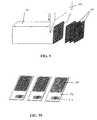
- FIG. 11shows a cross-sectional view of a portion of a slab 130.
- the slab 130has a plurality of evenly spaced parallel channels 132 formed into a top surface 134.
- the channelscan be made by any of a variety of known methods. If the material is glass, the channels may be etched, pressed, or created by precision rolling.
- the slabmay be formed by injection molding techniques, for example.
- FIG. 12shows a partial cross sectional view of a plurality of slabs 130 piled one on another. The bottom surface 136 of each slab 130 serves to close the channels 132 of the slab immediately beneath it. A top piece 138 without channels seals the channels of the topmost slab. The entire construct is then heated to a temperature such that the slabs fuse together thereby creating a block 140 capable of being redrawn as shown in FIG. 13. Blocks having any number of channels having any size diameter or shape may be formed using this technique.
- any block made from a thermoplastic material having a plurality of parallel channels formed therethroughmay be redrawn in order to form the device of the present invention.
- an alternative method for making a capillary reservoir deviceis to bind together a plurality of individual tubes or capillaries.
- the tubesmay be bound together into a bundle having any number of tubes.
- the bundleis then redrawn and finished in the same fashion as an extruded and redrawn block.
- FIG. 2shows the output end 20 of such a bundle of capillary tubes 22 after redraw.
- the tubes 22serve the same function as the channels 12 of the device of FIG. 1. But for specific references to figures, the terms channel and tube are analogous hereinafter while describing the device.
- the planar cut that exposes the output face of the device of either FIG. 1 or FIG. 2,is preferably non-wetting.
- the tube interior 24preferably has a wetting surface, while the tube ends 26 are preferably non-wetting.
- the interior walls of the channels 12 of the device of FIG. 1are wetting, while the wall ends are non-wetting. Because of the wetting channel interior and non-wetting end of each channel, droplets of liquid tend to bead on the end of each channel.
- the wetting characteristics of the output facemay be obtained in the same way.
- a device made of a material that is only moderately wettingsuch as polystyrene is to water, or non-wetting such as polyolefins such as polyethylene and polypropylene are to water
- wettabilitycan be improved with oxidizing treatments.
- oxidizing chemical etchantssuch as sulfuric or chromic acids may be introduced to the channel interiors.
- FIG. 3illustrates how liquid 28 from a reservoir 30 coats the interior 24 of the tubes 22 on the output end 20 of the device of FIG. 2.
- the deviceis next sliced in a direction perpendicular to the channels' length with a dicing machine as shown in FIG. 4.
- the dicingexposes the natural non-wetting or less wetting output face of the polymer.
- FIG. 4illustrates a planar cut of the output end 20 of the device of FIG. 2 being made with a dicing machine 32.
- the cutexposes tube ends 26 that are non-wetting, while the tube interior 24 remains wetting due to the coating received from liquid 28 within the reservoir 30.
- the cut tube fragments 34are discarded.
- the output portion of the device which has been cut and finishedmay be pressed against a rubber stamp coated with a non-wetting coating, for example a silane having a CF 3 termination, octadecyltriethoxysilane (OTS), or polydimethylsiloxane (PDMS).
- a non-wetting coatingfor example a silane having a CF 3 termination, octadecyltriethoxysilane (OTS), or polydimethylsiloxane (PDMS).
- OTSoctadecyltriethoxysilane
- PDMSpolydimethylsiloxane
- the output endmay be dipped into a solution that imparts non-wetting characteristics such as fluorodecyltrichlorosilane solution, for example, while gas flow is injected into the input end of the capillary array to prevent the solution from entering the channel interiors.
- a solution that imparts non-wetting characteristicssuch as fluorodecyltrichlorosilane solution, for example, while gas flow is injected into the input end of the capillary array to prevent the solution from entering the channel interiors.
- fluidis loaded into the input end of the device.
- the inputis compatible with macroscopic fluid loading, and loading may be accomplished through any variety of known means including: pipette, syringe, pumps, multiple pipette or syringe systems, funnels, etc.
- the center spacing between channels at the input endpreferably corresponds to the center spacing of a multiwell plate, a 1536 well plate for example.
- fluids contained individually in each well of a 1536 well platemay be loaded by forcing the fluid through a hole in the bottom of each well in the 1536 well plate into corresponding channels in the capillary reservoir device.
- Each channelis self contained, so potentially 10,000 different fluids can be loaded into the device. It is important to note that the number of channels is entirely variable and the number 10,000 was chosen simply as an example of a preferred embodiment.
- each channel's volumeis determined by its internal dimensions including the height of the device. Ideally, each channel will contain 5 to 500 microliters, but any volume is possible as determined by the variable dimensions: pitch of channel at top and bottom, and height of the device.
- the pitch of the channel at the output endis such that liquid will be retained within each channel by capillary force. This way, liquid will remain in each channel until forced out by some external force.
- each channelis filled with a different binding entity held within a liquid matrix.
- Binding entitiesare generally termed as a biological or synthetic molecule having a specific affinity for another molecule, through covalent bonding or non-covalent bonding.
- a specific binding entitycontains (either by nature or by modification) a functional chemical group (primary amine, sulfhydryl, aldehyde, etc.), a common sequence (nucleic acids), an epitope (antibodies), a hapten, or a ligand, that allows it to covalently react or non-covalently bond to a common function group on the surface of a substrate.
- Specific binding entitiesinclude, but are not limited to: deoxyribonucleic acids (DNA), ribonucleic acids (RNA), synthetic oligonucleotides, antibodies, proteins, peptides, lectins, modified polysaccharides, synthetic composite macromolecules, functionalized nanostructures, synthetic polymers, modified/blocked nucleotides/nucleosides, modified/blocked amino acids, fluorophores, chromophores, ligands, chelates and haptens.
- DNAdeoxyribonucleic acids
- RNAribonucleic acids
- synthetic oligonucleotidesantibodies
- proteinsproteins
- peptideslectins
- modified polysaccharidessynthetic composite macromolecules
- functionalized nanostructuressynthetic polymers
- modified/blocked nucleotides/nucleosidesmodified/blocked amino acids
- fluorophoreschromophores
- ligandsligands
- chelates and haptens
- application for this deviceare not limited to biological materials, but may extend to any chemistry capable of being in liquid form or in a suspension including but not limited to emulsions, particle suspensions, and coacervates.
- the liquid that contains the binding entityis preferably an acrylamide monomer, but may be any biocompatible polymerizable material.
- the acrylamideprovides the necessary cross-linking required for DNA or other biomolecule immobilization.
- 10,000 different acrylamide solutions, each containing an oligimer of slightly different nucleotide sequenceare loaded into each channel through means of a multiwell plate as previously described, by multiwell pipette, syringe, etc. Droplets will be elicited from each channel simultaneously by means of photon pressure, external pressure, etc. The drops are contacted against the substrate and thereby deposited.
- the acrylamideis preferably polymerized by ultra-violet radiation immediately after deposition onto the substrate.
- the resultant array of polymerized dropsis characterized in that the pitch between drops on the substrate is substantially identical to the pitch between channels on the output face of the device.
- Each dropletoccupies an identifiable position in the overall array, and the biomolecules within each drop are covalently bound to the polymerized acrylamide.
- the biomolecules, in this embodiment - oligonucleotides,are covalently bound to the codeposited polymerized acrylamide.
- the substratemay be biological, nonbiological, organic, inorganic, or a combination of any of these, existing as particles, strands, precipitates, gels, sheets, tubing, spheres, beads, porous beads, containers, capillaries, pads, slices, films, plates, slides, membranes, etc.
- the substratemay have any convenient shape, such as a disc, square, rectangle, sphere, etc.
- the substrateis preferably flat, but may take on a variety of alternative surface configurations.
- the substratemay contain raised or depressed regions on which liquid is deposited.
- the substratemay be glass, polymer or membrane into which channels have been etched; or it may contain regions that have been made porous by means of a chemical etchant.
- the substrate and its surfacepreferably form a rigid support on which a liquid with the appropriate surface energy and containing a binding entity can be deposited, and which is preferably functionalized with an organosilane such as gamma-aminopropyl triethoxysilane or methacryloxypropyltriethoxysilane, for example.
- organosilanesuch as gamma-aminopropyl triethoxysilane or methacryloxypropyltriethoxysilane, for example.
- the substrateis flat glass, preferably a bomsilicate glass having surface relief features of less than 10 nanometers.
- the surface of the glass substratemay be coated with, a non-wetting agent such as fluorodecyltrichlorosilane or ocyadecyltrichlorosilane, for example.
- the coatingmay be selectively removed by using known methods of photoresist or selectively applied using masking techniques.
- an array of positions that are uncoated and thereby wettingis presented.
- the spacing in the wetting/non-wetting positional arraypreferably corresponds to the spacing between channels on the output face of the capillary reservoir device.
- the present inventioninvolves a technique that eliminates the need for liquid handling as between the capillary reservoir device and a substrate.
- a capillary reservoir devicethat preferably has 1,000 or more channels and is preferably comprised of an organic polymer such as polystyrene, is redrawn down (as shown in FIG. 6) to a predetermined size and elongated such that a reduced linear portion 40 of substantially uniform cross sectional size is created at the outlet end 42.
- FIG. 5shows the initial extrusion of a preform block 44, through a die 40, and prior to redraw. Each channel of the resultant redrawn device 48 is then filled with a liquid.
- Each liquidis a different mixture of a particular binding entity and a thermally activated curing polymer such as an epoxy resin (EPON).
- each channelmay contain a different aminated oligonucleotide or cDNA which is combined with the epoxy resin.
- An epoxide group from the epoxy resinwill covalently react with the amine creating a crosslinked polymer network.
- a different known oligonucleotide or cDNA fragmentis selected for each individual channel and combined with the epoxy.
- the various mixturesare entered into the many channels, the entire device is cured, for example in a 6 hour cycle at 40°C, or more preferably 2 days at room temperature in order to limit gas production caused by the polymerization reaction.
- FIG. 7shows the device of FIG. 6 undergoing a curing step.
- the curingmay be performed by gamma radiation, blue light, temperature activation, or room temperature curing, for example.
- the reduced sized portion 40is cut from the rest of the device and preferably frozen down to -40°C, below the polymer glass transition temperature.
- the freezing stepmakes the epoxy matrix and polymer brittle thereby facilitating a clear cut by fracturing. Cutting by fracturing reduces the chance of crosstalk contamination as between neighboring channels as the blade passes through. Further, deformation or distortion of the array is prevented with this type of cutting technique.
- FIG. 9shows very fine slices 54 being cut from a frozen block 50 with a tomography cutting tool 52, such as a diamond blade or glass blade, for example.
- a tomography cutting tool 52such as a diamond blade or glass blade, for example.
- Each slice 54is preferably approximately between 4 and 10 ⁇ m in thickness, although any slice thickness may be possible.
- Each slicealso contains 10,000 different binding entities suspended in the cured epoxy resin matrix as a result of the channel filling.
- the slicetakes the form of a sheet comprising a lattice network formed by the channel walls and defining a plurality of containment spaces each having sidewalls and an open top and bottom, and a different known binding entity occupying each containment space.
- a preferably flat substrate slide 56preferably made of either glass or an organic polymer, by means of ultrasonic welding or gluing, for example.
- the walls of the channelsserve as boundaries for elimination of crosstalk between samples.
- the material of the capillary reservoir deviceis preferably opaque, and more preferably black. This way, optical crosstalk that often results as a consequence of fluorometric, chemiluminescent or colorimetric assays may be reduced as between different samples.
- Bar coding 57may be employed as a means of recording the contents of each well or position on the array. Proper alignment of the slice on the substrate can be assured by a feature such as a beveled edge (not shown).
- the slidemay be packaged for transport and subsequent use in any variety of research or diagnostic procedures.
- liquid suspension including synthesized biomolecules covalently attached to beadsmay be used along with the resin to fill the chatmels and become part of the polymer network upon curing.
Landscapes
- Chemical & Material Sciences (AREA)
- Health & Medical Sciences (AREA)
- Engineering & Computer Science (AREA)
- Chemical Kinetics & Catalysis (AREA)
- Organic Chemistry (AREA)
- Life Sciences & Earth Sciences (AREA)
- Immunology (AREA)
- Clinical Laboratory Science (AREA)
- Materials Engineering (AREA)
- Hematology (AREA)
- General Health & Medical Sciences (AREA)
- Analytical Chemistry (AREA)
- Biomedical Technology (AREA)
- General Physics & Mathematics (AREA)
- Urology & Nephrology (AREA)
- Biochemistry (AREA)
- Physics & Mathematics (AREA)
- Manufacturing & Machinery (AREA)
- Molecular Biology (AREA)
- Pathology (AREA)
- General Life Sciences & Earth Sciences (AREA)
- Biotechnology (AREA)
- Cell Biology (AREA)
- Microbiology (AREA)
- Dispersion Chemistry (AREA)
- Geochemistry & Mineralogy (AREA)
- Food Science & Technology (AREA)
- Medicinal Chemistry (AREA)
- Apparatus Associated With Microorganisms And Enzymes (AREA)
- Investigating Or Analyzing Non-Biological Materials By The Use Of Chemical Means (AREA)
- Automatic Analysis And Handling Materials Therefor (AREA)
- Devices For Use In Laboratory Experiments (AREA)
Description
- The invention relates to a method of depositing an array of biological samples onto a substrate.
- Hybridization is a hydrogen- bonding interaction between two nucleic acid strands that obey the Waison-Crick complementary rules. All other base pairs are mismatches that destabilize hybrids. Since a single mismatch decreases the melting temperature of a hybrid by up to 10°C, conditions can be found in which only perfect hybrids can survive. Hybridization comprises contacting the strands, one of which is usually immobilized on a solid support and the other usually bears a radioactive, chemiluminescent or fluorescent label, and then separating the resulting hybrids from the unreacted labeled strands by washing the support. Hybrids are recognized by detecting the label bound to the surface of the support.
- Oligonucleotide hybridization is widely used to determine the presence in a nucleic acid of a sequence that is complimentary to the oligonucleotide probe. In many cases, this provides a simple, fast, and inexpensive alternative to conventional sequencing methods. Hybridization does not require nucleic acid cloning and purification, carrying out base-specific reactions, or tedious electrophoretic separations. Hybridization of oligonucleotide probes has been successfully used for various purposes, such as analysis of genetic polymorphisms, diagnosis of genetic diseases, cancer diagnostics, detection of viral and microbial pathogens, screening of clones, genome mapping and ordering of fragment libraries.
- An oligonucleotide array is comprised of a number of individual oligonucleotide species tethered to the surface of a solid support in a regular pattern, each species in a different area, so that the location of each oligonucleotide is known. An array can contain a chosen collection of oligonucleotides, e.g., probes specific for all known clinically important pathogens or specific for all known clinically important pathogens or specific for all known sequence markers of genetic diseases. Such an array can satisfy the needs of a diagnostic laboratory. Alternatively, an array can contain all possible oligonucleotides of a given lengthn. Hybridization of a nucleic acid with such a comprehensive array results in a list of all its constituent n-mers, which can be used for unambiguous gene identification (e.g., in forensic studies), for determination of unknown gene variants and mutations (including the sequencing of related genomes once the sequence of one of them is known), for overlapping clones, and for checking sequences determined by conventional methods. Finally, surveying then-mers by hybridization to a comprehensive array can provide sufficient information to determine the sequence of a totally unknown nucleic acid.
- Oligonucleotide arrays can be prepared by synthesizing all the oligonucleotides, in parallel, directly on the support, employing the methods of solid-phase chemical synthesis in combination with site-directing masks as described in US Pat. 5,510,270. Four masks with non-overlapping windows and four coupling reactions are required to increase the length of tethered oligonucleotides by one. In each subsequent round of synthesis, a different set of four masks is used, and this determines the unique sequence of the oligonucleotides synthesized in each particular area. Using an efficient phomlithographic technique, miniature arrays containing as many as 105 individual oligonucleotides per cm2 of area have been demonstrated.
- Another technique for creating oligonucleotide arrays involves precise drop deposition using a piezoelectric pump as described in US Pat. 5,474,796. The piezoelectric pump delivers minute volumes of liquid to a substrate surface. The pump design is very similar to the pumps used in ink jet printing. This picopump is capable of delivering 50 micron diameter (65 picoliter) droplets at up to 3000 Hz and can accurately hit a 250 micron target The pump unit is assembled with five nozzles array heads, one for each of the four nucleotides and a fifth for delivering activating agent for coupling. The pump unit remains stationary while droplets are fired downward at a moving array plate. When energized, a microdroplet is ejected from the pump and deposited on the array plate at a functionalized binding site. Different oligonucleotides are synthesized at each individual binding site based on the microdrop deposition sequence.
- Another approach using arrays is the pin dipping method for parallel oligonucleotide synthesis. Geysen,J Org. Chem. 56, 6659 (1991). In this method, small amounts of solid support are fused to arrays of solenoid controlled polypropylene pins, which are sequentially dipped into trays of the appropriate reagents. The density of the arrays is limited by this process.
- Further approaches to forming an array involve taking presynthesized oligonucleotide or cDNA sequences from separately prepared aqueous mixtures and transferring them to substrate either individually or in some small multiple. This may be accomplished for example by repeatedly contacting a substrate surface with typographic pins holding droplets, using ink jet printing mechanisms to lay down an array matrix, or by use of a pen plotter. These printing processes are limited by the time and expense required in transferring 103 or greater different sequence mixtures onto defined positions on a substrate.
- US-A-4 010 019 relates to a method of making glass microchannel plates by drawing bundles of large numbers of glass rubes sufficiently to reduce the cross-sectional sizes of openings through the tubes to desired microchannel size with minimal distortion of original tube shape and wall thickness in resulting assemblies.
- US-A-5 265 327 relates to a process of fabricating microchannel plates in which a ribbon of green glass/ceramic powder in a binder and solvent slurry is configured in complementary microchannel forming grooves, partially dried and then carefully stacked. The stack is cut into segments for final solidification by heat fusing and curing and sliced.
- The abstract of JP-A-06 294771 (Patent Abstracts of Japan) relates to obtaining an electrophoretic device having a capillary array which holds the features of a capillary system.
- US-A-5 508 200 relates to a system for high performance automated chemical analysis which may include a dispenser which uses inkjet printing technology to dispense measured amounts of a reagent or sample.
- WO-A-95 35505 relates to forming microarrays of biological samples on a support by a method which involves dispensing a known volume of a reagent at each of selected array positions by tapping a capillary dispenser on the support under conditions effective to draw a defined volume of liquid onto the support.
- US-A-4 446 104 relates to a device for transferring sample vessels carried by a microtiter member to collecting vessels which are carried in cassettes and are dimensioned to accommodate the sample vessels.
- US-A-5 560 811 relates to a method of multiplexing electrophoresis analysis in which an array of samples in multi-well plates are simultaneously transferred to an array of electrophoresis columns where electrophoresis is simultaneously carried out followed by analysis of the columns.
- WO-A-95 25116 relates to a method for preparing a substrate on which microdrop-sized loci are located at which chemical compounds are synthesised or diagnostic tests are conducted. The loci are formed by applying microdrops from a dispenser from which a microdrop is pulse fed onto the surface of the substrate.
- The present invention provides a method of depositing an array of biological samples onto a substrate comprising the steps of:
- a) providing a device having a plurality of open ended channels extending from an input face to an output face wherein at least along a predetermined length, each channel decreases approximately equally in diameter, cross sectional area, and wall thickness;
- b) filling at least one said channel with a liquid that is capable of hardening under proper conditions;
- c) allowing said liquid to harden;
- d) slicing a section of said device; and
- e) bonding said sliced section to said substrate.
- FIG. 1 is a three dimensional view of the device of the present invention.
- FIG. 2 is a plurality of connected capillary tubes prior to redraw.
- FIG. 3 is an illustration of the output end of the device being dipped into a liquid reservoir in order to impart wettable characteristics to the interior of the channels.
- FIG. 4 is an illustration of the output end of the device being trimmed in order to expose a non wetting surface.
- FIG. 5 is a three dimensional view of a preform block of material that is being extruded through a honeycomb die.
- FIG. 6 is a three dimensional view of an extruded block that has been subsequently redrawn.
- FIG. 7 is a side view of an extruded block that has been subsequently redrawn and is being subjected to a curing process.
- FIG. 8 is a three dimensional view of a series of blocks that have been cut from the redrawn portion of the device of FIG. 7.
- FIG. 9 is a three dimensional view of a block of FIG. 8 being sliced by a blade.
- FIG. 10 is a three dimensional view of three high density array plates of the present invention.
- FIG. 11 is a partial cross sectional view of a slab of material which when assembled with other like slabs forms a preform.
- FIG. 12 is a partial cross sectional view of a plurality of slabs piled one upon another and prior to fusion.
- FIG. 13 is a partial cross sectional view of a preform formed by fusing the slabs of FIG. 12.
- Glass and organic polymer redraw processes are well known and have been used to form precision tubing, sheets and fiber bundles with complex cross sections. The known redraw technique can be adapted to form a device having a plurality of open ended channels for use according to the present invention.
- The redraw technique is instituted on a multi-celled extruded block, also referred to as a honeycomb substrate, or a collection of connected capillary tubes. An important aspect of the redraw technique is that relatively large glass or polymer structures having complex cross-sectional configurations, corresponding to complex cross-sectional configurations of the final product may be easily formed to desired dimensions. During the redrawing or stretching process, all cross-sectional dimensions and areas are uniformly reduced while the present tolerance remains constant. Thus, for purposes of illustration, a 2.54 cm (1 inch) dimension having a tolerance of 1% e.g., ±0.0254 cm (0.01 inch), in a 10 to 1 reduction results in a 0.254 cm (0.1 inch) dimension and a tolerance of ± 0.00254 cm (0.001 inch). A further 10 to 1 reduction results in a 0.0254 cm (0.01 inch) dimension and a tolerance of ±0.000254 cm (0.0001 inch).
- In order to form a capillary reservoir device from glass, glass ceramic, or ceramic material, one must use a thermoplastic binder such as paraffin wax or a binder as described in US Patent 5,602,197, and combine it with an inorganic powdered material, preferably PYREX 7761 powder with frit size centered on 10 µm. This organic/inorganic mixture is then extruded through a counter rotating twin screw extruder, operated at room temperature. A die determines the dimensions of the extruded material. Preferably, a 5.08-17.78 cm (2-7 inch) diameter, square or round channeled, monolithic honeycomb preform with 635-381 µm (25-15 mil) channel walls and 31-62 cells per square centimetre (200-400 cells per square inch) of frontal area results from the extrusion. The preform may be extruded in either round, rectangular or square cross sectional shape. The cross sectional shape of the cells may be any shape as determined by the die. The organic binder must be carefully removed by heating slowly to a sufficient temperature to cause volatilization and pyrolysis of the organic binder. Slump and other distortion is avoided by careful selection and control of the rheology, inorganic volume loading, and binder pyrolytic/volatilization characteristics. After binder removal, the preform of packed particulates is then sintered to meld the powder particles, while keeping the shape. In order to control wall sagging, sintering conditions must be closely monitored. The preform is preferably sintered vertically in order to avoid distortion. Sintering condition for PYREX 7761 is approximately 675° C for 1 hour. At this temperature, glass particle binding occurs and 10-15% shrinkage uniformly occurs throughout the structure. What remains is a glass, glass ceramic, or ceramic depending on the sintering schedule and the composition of the original powder material. For use with this invention, preferably the firing schedule and powder composition should be modified in such a way as to create substantially identical channel walls of high density and no open porosity. The resulting honeycomb block has a plurality of parallel channels or cells extending therethrough. The block may be any length as determined by the point at which it is cut from the extruder.
- Table 1 shows the composition of PYREX 7761 glass. The inorganic powder is made from PYREX 7761 cullet: crushed, magnetically separated, ball milled (alumina), and ultrasonically screened (-325 mesh).
Table 1 Compound Weight Percent (%) SiO2 78.92 K2O 2.76 B2O3 18.27 - Table 2 shows the batch composition of the extrudable mixture.
Table 2 Ingredients Weight (grams) PYREX 7761 powder 7938 Oleic Acid 80 Dow F-40M METHOCEL 558 Water (DI) 1985 - The inorganic powder, the METHOCEL, and the Oleic Acid are blended together in a LITTLEFORD mixer, and then mulled together with the water addition in a LANCASTER mixer. The mix is then further mixed by evacuation and spaghetti extrusion (3 times). Finally, the batch is extruded through a die to be formed into a multi-celled preform which is cut from the extrudate, ready for sintering.
- Table 3 shows the furnace schedule used to sinter the preforms. The preforms are vertically suspended during sintering to minimize bowing.
Table 3 Furnace Schedule 1) Room Temperature to 300°C at 50°C/hr. 2) 300°C to 550°C at 20°/hr. 3) 550°C to 700°C at 50°C/hr. 4) Hold at 700°C for 2 hours. 5) 700°C to Room Temperature (power off). - Once the preform is sintered, the resulting structure is heated and undergoes a redraw reduction. Redraw takes place approximately at approximately 20° C to 100° C above the glass transformation temperature. For PYREX 7761, the sintered block is reheated to 870° C over approximately 1.5 hours, in order to reach a -/- 20° C temperature uniformity within the section of the block to be stretched. The redraw process occurs in two steps; first, the block is arranged such that the channels are aligned vertically; and, a portion of the extruded block is restrained, while the weight of the structure is allowed to pull the unrestrained portion downward. Second, a constant force is applied to the unrestrained portion to further facilitate the draw. Once the extruded block is stretched to a predetermined diameter, depending on the cross sectional size requirement for the output end of the device, the process is stopped by temperature reduction. This annealing step preferably occurs over one hour in which the temperature is dropped to 20°C. As an example, for a 180 mm long cylindrical block having a 22 mm cross sectional diameter to be drawn to a cross sectional diameter of 4.2 mm, the block must be drawn approximately 920 mm in length. It is preferred that, after redrawing, the length of the capillary reservoir device be between 2 and 3 times the diameter of the block prior to redraw, in order to optimize the liquid retaining capillary characteristics of the individual channels.
- In producing a bent reservoir device, as required in some embodiments, the drawn piece is maintained at a temperature of approximately 850°C in the portion to be bent. The piece is removed from the oven and bent at the appropriate angle, 180° for example. After bending, the piece is placed in an annealing oven in order to cool to room temperature without thermal stress.
- After annealing to approximately 20°C over the course of approximately 1 hour, the piece whether bent or not, is cut on the reduced section of the block, which becomes the output face of the device, and may also be cut on the loading or input end by a diamond saw for example. The cutting is preferably performed under internal water flux in order to prevent any glass chips or fragments from lodging in the channels. The output face of the piece can then be finished by successively polishing with 12 µm, 3 µm, 1 µm, and 0.3 µm grit polishing paper. The device may be further finished under fire polish at approximately 450°C for one hour.
- Optionally, when using a binder such as those disclosed in U.S. Pat. 5,602,197, the option exists to redraw the preform after extrusion, but prior to binder removal and sintering. Redraw in this case is done as it would be for a thermoplastic polymer in that the preform, or the section of the preform to be redrawn, is reheated to a softened or partially melted state whereupon the preform is redrawn by stretching. An advantage of using this technique is that inorganic particulates can be used that cannot be redrawn in the inorganic state, such as zirconia, alumina, etc.
- In an embodiment in which a capillary reservoir device is made from a thermoplastic polymer, the polymer is initially extruded through a twin screw extruder and die operating at the melting temperature of the thermoplastic material, for example, polypropylene is extruded at approximately 180°C. The target cell density and wall thickness is substantially the same as the glass embodiment discussed above. Once the block has been extruded, the polymer redraw is performed as above and may require external heating of the structure, or the section to be redrawn, to 150°C, for example in polypropylene. The redraw may also require internal heating of the polymer structure by means of forced heated air, for example, in order to preclude any internal heating gradient within the structure during redraw. Although the extrusion has been demonstrated with a polyolefin, specifically, polypropylene, it should be understood that any thermoplastic polymer, as recognized by one skilled in the art, may be used for this process.
- Although a cylindrical extrusion is easier to perform in both powdered glass and plastic, a square or rectangular extrusion is preferred in order create a device capable of depositing a rectilinear array.
- Both extrusion of the polymer and the powdered glass is ideally performed by a vertical extrusion process. Vertical extrusion helps reduce problems of wall sagging due to gravitational effects. However, a horizontal extrusion process may be preferred in a mass production setting.
- Yet another option for drawing down an extruded cellular body is to fill in the open cells of an extruded preform with a molten wax that exhibits similar plastic properties to the wet batch when solidified. The cooled body, consisting of the wet extruded cellular preform and the solidified plastic wax in the cells, is then pushed through a size reducing die at room temperature. By partially pushing the composite body through a die, a body with the desired transition from large to small cells may be obtained. Afterwards, the wax is melted and removed; then the cellular body is dried, fired and finished in the normal manner. A suitable wax for this technique is a microcrystaline hydrocarbon wax with a high needle penetration hardness (15+). This alternative drawdown technique is more fully disclosed in commonly assigned U.S. Patent No 6,299,958.
- FIG. 1 shows a
capillary reservoir device 10 for use according to the present invention. In a preferred embodiment, the device ideally comprises a matrix ofsquare channels 12, 100 channels along eachouter wall 14 of the structure and 10,000 in total. The top of the device is theinput end 16 of the device. The exposed face of the input end shall be called the input face. Each side of theinput end 16 of the device is approximately 112.5 mm. The surface area of the entire input face, in this embodiment, is approximately 12,656 mm2. The structure has been redrawn such that the length of each side on theoutput end 18 of the matrix is approximately 22 mm. The exposed face of the output end shall be called the output face. The surface area of the output face is approximately 484 mm2. Eachchannel 12 within thedevice 10 is self contained and decreases in cross sectional area in approximate proportion to the decrease in total cross sectional surface area. Thereby, a channel having a width or pitch of 1.125 mm at the top surface, as in FIG. 1, has a width or pitch of approximately 0.22 mm at the bottom surface. The surface area of a cross-section of one individual channel as a proportion of the cross sectional area of a perpendicular plane taken at any point along the height of the vertical standing device is approximately constant. Wall thickness may increase slightly as a proportion of the total cross sectional area as the device is redrawn, but the number of channels is constant as well as the relative position of each channel in the matrix as defined by the on-center channel to channel pitch. Put another way, the device has a plurality of open ended channels extending from an input face to an output face wherein at least along a predetermined length, each channel decreases equally in diameter, cross sectional area, and wall thickness. - Another alternative for making a capillary reservoir device is to etch or press channels in a surface of a plurality of slabs, pile the slabs one upon another forming a block having a plurality of channels formed therethrough, fusing the slabs, and redrawing the entire structure. Creating a preform by this method is shown in FIGS. 11 and 12. FIG. 11 shows a cross-sectional view of a portion of a
slab 130. Theslab 130 has a plurality of evenly spacedparallel channels 132 formed into atop surface 134. The channels can be made by any of a variety of known methods. If the material is glass, the channels may be etched, pressed, or created by precision rolling. If the material is a polymer, the slab may be formed by injection molding techniques, for example. FIG. 12 shows a partial cross sectional view of a plurality ofslabs 130 piled one on another. The bottom surface136 of eachslab 130 serves to close thechannels 132 of the slab immediately beneath it. Atop piece 138 without channels seals the channels of the topmost slab. The entire construct is then heated to a temperature such that the slabs fuse together thereby creating ablock 140 capable of being redrawn as shown in FIG. 13. Blocks having any number of channels having any size diameter or shape may be formed using this technique. - Virtually any block made from a thermoplastic material having a plurality of parallel channels formed therethrough may be redrawn in order to form the device of the present invention.
- It should be noted that an alternative method for making a capillary reservoir device is to bind together a plurality of individual tubes or capillaries. The tubes may be bound together into a bundle having any number of tubes. The bundle is then redrawn and finished in the same fashion as an extruded and redrawn block. FIG. 2 shows the
output end 20 of such a bundle ofcapillary tubes 22 after redraw. Thetubes 22 serve the same function as thechannels 12 of the device of FIG. 1. But for specific references to figures, the terms channel and tube are analogous hereinafter while describing the device. - As an example to demonstrate feasibility, 22
tubes 22 were bonded together in rows of 7, 8 and 7 tubes. The matrix of 9 mm tubes was then redrawn such that tube to tube center spacing became 350 µm, and the diameter of the capillary output opening in each tube was 180 µm. - The planar cut that exposes the output face of the device of either FIG. 1 or FIG. 2, is preferably non-wetting. For example, in FIG. 2, the
tube interior 24 preferably has a wetting surface, while the tube ends26 are preferably non-wetting. Similarly, the interior walls of thechannels 12 of the device of FIG. 1 are wetting, while the wall ends are non-wetting. Because of the wetting channel interior and non-wetting end of each channel, droplets of liquid tend to bead on the end of each channel. - Whether the device is made from a redraw of an extruded block or assembled block, or from bonded capillary tubes, the wetting characteristics of the output face may be obtained in the same way. To obtain the wettability characteristics of the output face in a device made of a material that is only moderately wetting, such as polystyrene is to water, or non-wetting such as polyolefins such as polyethylene and polypropylene are to water, wettability can be improved with oxidizing treatments. For example, oxidizing chemical etchants such as sulfuric or chromic acids may be introduced to the channel interiors. One way of subjecting the channel interiors to the oxidizing etchant, or any other liquid that will coat the interior channel walls is illustrated in FIGS. 3-5. FIG. 3 illustrates how liquid28 from a
reservoir 30 coats theinterior 24 of thetubes 22 on theoutput end 20 of the device of FIG. 2. The device is next sliced in a direction perpendicular to the channels' length with a dicing machine as shown in FIG. 4. The dicing exposes the natural non-wetting or less wetting output face of the polymer. FIG. 4 illustrates a planar cut of theoutput end 20 of the device of FIG. 2 being made with a dicingmachine 32. The cut exposes tube ends26 that are non-wetting, while thetube interior 24 remains wetting due to the coating received fromliquid 28 within thereservoir 30. Thecut tube fragments 34 are discarded. - With a device made of a naturally wetting material, such as glass is to water, the output portion of the device which has been cut and finished may be pressed against a rubber stamp coated with a non-wetting coating, for example a silane having a CF3 termination, octadecyltriethoxysilane (OTS), or polydimethylsiloxane (PDMS). The silane is transferred to the output face of the device, making the surface non-wetting. The interior of the channels made of glass are naturally wetting. Alternatively, the output end may be dipped into a solution that imparts non-wetting characteristics such as fluorodecyltrichlorosilane solution, for example, while gas flow is injected into the input end of the capillary array to prevent the solution from entering the channel interiors. This way, output face obtains a non-wetting characteristic, while the channel interiors remain uncoated, and thereby retain their wetting characteristic.
- Once formed, the operation of a device whether made of an organic polymer or glass is substantially the same. In operation, fluid is loaded into the input end of the device. The input is compatible with macroscopic fluid loading, and loading may be accomplished through any variety of known means including: pipette, syringe, pumps, multiple pipette or syringe systems, funnels, etc. Preferably, the center spacing between channels at the input end preferably corresponds to the center spacing of a multiwell plate, a 1536 well plate for example. This way, fluids contained individually in each well of a 1536 well plate may be loaded by forcing the fluid through a hole in the bottom of each well in the 1536 well plate into corresponding channels in the capillary reservoir device. Each channel is self contained, so potentially 10,000 different fluids can be loaded into the device. It is important to note that the number of channels is entirely variable and the number 10,000 was chosen simply as an example of a preferred embodiment.
- Each channel's volume is determined by its internal dimensions including the height of the device. Ideally, each channel will contain 5 to 500 microliters, but any volume is possible as determined by the variable dimensions: pitch of channel at top and bottom, and height of the device.
- Ideally, the pitch of the channel at the output end is such that liquid will be retained within each channel by capillary force. This way, liquid will remain in each channel until forced out by some external force.
- In a preferred embodiment, each channel is filled with a different binding entity held within a liquid matrix. "Binding entities" are generally termed as a biological or synthetic molecule having a specific affinity for another molecule, through covalent bonding or non-covalent bonding. Preferably, a specific binding entity contains (either by nature or by modification) a functional chemical group (primary amine, sulfhydryl, aldehyde, etc.), a common sequence (nucleic acids), an epitope (antibodies), a hapten, or a ligand, that allows it to covalently react or non-covalently bond to a common function group on the surface of a substrate. Specific binding entities include, but are not limited to: deoxyribonucleic acids (DNA), ribonucleic acids (RNA), synthetic oligonucleotides, antibodies, proteins, peptides, lectins, modified polysaccharides, synthetic composite macromolecules, functionalized nanostructures, synthetic polymers, modified/blocked nucleotides/nucleosides, modified/blocked amino acids, fluorophores, chromophores, ligands, chelates and haptens. The term "biomolecule" and "binding entity" are interchangeable for purposes of this disclosure.
- It should be noted that application for this device are not limited to biological materials, but may extend to any chemistry capable of being in liquid form or in a suspension including but not limited to emulsions, particle suspensions, and coacervates.
- The liquid that contains the binding entity is preferably an acrylamide monomer, but may be any biocompatible polymerizable material. The acrylamide provides the necessary cross-linking required for DNA or other biomolecule immobilization. In a preferred embodiment, 10,000 different acrylamide solutions, each containing an oligimer of slightly different nucleotide sequence are loaded into each channel through means of a multiwell plate as previously described, by multiwell pipette, syringe, etc. Droplets will be elicited from each channel simultaneously by means of photon pressure, external pressure, etc. The drops are contacted against the substrate and thereby deposited. Next, the acrylamide is preferably polymerized by ultra-violet radiation immediately after deposition onto the substrate. The resultant array of polymerized drops is characterized in that the pitch between drops on the substrate is substantially identical to the pitch between channels on the output face of the device. Each droplet occupies an identifiable position in the overall array, and the biomolecules within each drop are covalently bound to the polymerized acrylamide. The biomolecules, in this embodiment - oligonucleotides, are covalently bound to the codeposited polymerized acrylamide.
- Any conceivable substrate may be employed in this invention. The substrate may be biological, nonbiological, organic, inorganic, or a combination of any of these, existing as particles, strands, precipitates, gels, sheets, tubing, spheres, beads, porous beads, containers, capillaries, pads, slices, films, plates, slides, membranes, etc. The substrate may have any convenient shape, such as a disc, square, rectangle, sphere, etc. The substrate is preferably flat, but may take on a variety of alternative surface configurations. For example, the substrate may contain raised or depressed regions on which liquid is deposited. Further, the substrate may be glass, polymer or membrane into which channels have been etched; or it may contain regions that have been made porous by means of a chemical etchant. The substrate and its surface preferably form a rigid support on which a liquid with the appropriate surface energy and containing a binding entity can be deposited, and which is preferably functionalized with an organosilane such as gamma-aminopropyl triethoxysilane or methacryloxypropyltriethoxysilane, for example.
- In a preferred embodiment, the substrate is flat glass, preferably a bomsilicate glass having surface relief features of less than 10 nanometers. Although a non-patterned plate is preferred for droplet alignment issues, the surface of the glass substrate may be coated with, a non-wetting agent such as fluorodecyltrichlorosilane or ocyadecyltrichlorosilane, for example. The coating may be selectively removed by using known methods of photoresist or selectively applied using masking techniques. Preferably, an array of positions that are uncoated and thereby wetting is presented. The spacing in the wetting/non-wetting positional array preferably corresponds to the spacing between channels on the output face of the capillary reservoir device.
- The present invention involves a technique that eliminates the need for liquid handling as between the capillary reservoir device and a substrate. A capillary reservoir device that preferably has 1,000 or more channels and is preferably comprised of an organic polymer such as polystyrene, is redrawn down (as shown in FIG. 6) to a predetermined size and elongated such that a reduced
linear portion 40 of substantially uniform cross sectional size is created at theoutlet end 42. FIG. 5 shows the initial extrusion of apreform block 44, through adie 40, and prior to redraw. Each channel of the resultant redrawndevice 48 is then filled with a liquid. Each liquid is a different mixture of a particular binding entity and a thermally activated curing polymer such as an epoxy resin (EPON). As an example, each channel may contain a different aminated oligonucleotide or cDNA which is combined with the epoxy resin. An epoxide group from the epoxy resin will covalently react with the amine creating a crosslinked polymer network. A different known oligonucleotide or cDNA fragment is selected for each individual channel and combined with the epoxy. The various mixtures are entered into the many channels, the entire device is cured, for example in a 6 hour cycle at 40°C, or more preferably 2 days at room temperature in order to limit gas production caused by the polymerization reaction. FIG. 7 shows the device of FIG. 6 undergoing a curing step. The curing may be performed by gamma radiation, blue light, temperature activation, or room temperature curing, for example. - After curing, the reduced
sized portion 40 is cut from the rest of the device and preferably frozen down to -40°C, below the polymer glass transition temperature. The freezing step makes the epoxy matrix and polymer brittle thereby facilitating a clear cut by fracturing. Cutting by fracturing reduces the chance of crosstalk contamination as between neighboring channels as the blade passes through. Further, deformation or distortion of the array is prevented with this type of cutting technique. - The reduced
size portion 40 may then be chopped intoblocks 50 as shown in FIG. 8. FIG. 9 shows veryfine slices 54 being cut from afrozen block 50 with atomography cutting tool 52, such as a diamond blade or glass blade, for example. Eachslice 54 is preferably approximately between 4 and 10 µm in thickness, although any slice thickness may be possible. Each slice also contains 10,000 different binding entities suspended in the cured epoxy resin matrix as a result of the channel filling. The slice takes the form of a sheet comprising a lattice network formed by the channel walls and defining a plurality of containment spaces each having sidewalls and an open top and bottom, and a different known binding entity occupying each containment space. - After the slicing the
slice 54 is bonded to a preferablyflat substrate slide 56, as shown in FIG. 10, preferably made of either glass or an organic polymer, by means of ultrasonic welding or gluing, for example. The walls of the channels serve as boundaries for elimination of crosstalk between samples. Further, the material of the capillary reservoir device is preferably opaque, and more preferably black. This way, optical crosstalk that often results as a consequence of fluorometric, chemiluminescent or colorimetric assays may be reduced as between different samples.Bar coding 57 may be employed as a means of recording the contents of each well or position on the array. Proper alignment of the slice on the substrate can be assured by a feature such as a beveled edge (not shown). - Once bound to the substrate, the slide may be packaged for transport and subsequent use in any variety of research or diagnostic procedures.
- It should be noted that as in the method described above, the liquid suspension including synthesized biomolecules covalently attached to beads may be used along with the resin to fill the chatmels and become part of the polymer network upon curing.
- Although the invention has been described in detail for the purpose of illustration, it is understood that such detail is solely for that purpose and variations can be made therein by those skilled in the art.
Claims (12)
- A method of depositing an array of biological samples onto a substrate comprising the steps of:a) providing a device having a plurality of open ended channels extending from an input face to an output face wherein at least along a predetermined length, each channel decreases approximately equally in diameter, cross sectional area, and wall thickness;b) filling at least one said channel with a liquid that is capable of hardening under proper conditions;c) allowing said liquid to harden;d) slicing a section of said device; ande) bonding said sliced section to said substrate.
- The method of claim 1 further comprising the step of freezing the device after said hardening step and prior to said slicing step.
- The method of claim 2 further comprising the step of allowing the sliced section to thaw after said bonding step.
- The method of any of claims 1 to 3 wherein said sliced section is 4-10 µm in thickness.
- The method of any of claims 1 to 4 wherein said slicing step is performed by a microtome.
- The method of any of claims 1 to 5 wherein said bonding is ultrasonic bonding.
- The method of any of claims 1 to 6 wherein said substrate is optically clear.
- The method of any of claims 1 to 7 wherein said substrate is composed of a glass.
- The method of any of claims 1 to 7 wherein said substrate is composed of a thermoplastic polymer.
- The method of any of claims 1 to 6 wherein said device is composed of an opaque material.
- The method of any of claims 1 to 10 wherein said liquid contains a binding entity.
- The method of any of claims 1 to 11 wherein said binding entity is an oligonucleotide.
Priority Applications (13)
| Application Number | Priority Date | Filing Date | Title |
|---|---|---|---|
| DE69835342TDE69835342T2 (en) | 1998-04-27 | 1998-04-27 | Method for storing biological samples with the aid of a redrawn capillary store |
| EP98401021AEP0955084B1 (en) | 1998-04-27 | 1998-04-27 | Method of depositing an array of biological samples using a redrawn capillary reservoir |
| PCT/US1999/007844WO1999055460A1 (en) | 1998-04-27 | 1999-04-09 | Redrawn capillary imaging reservoir |
| CA002327664ACA2327664A1 (en) | 1998-04-27 | 1999-04-09 | Redrawn capillary imaging reservoir |
| EP99917389AEP1075327A4 (en) | 1998-04-27 | 1999-04-09 | Redrawn capillary imaging reservoir |
| CN99805597ACN1311717A (en) | 1998-04-27 | 1999-04-09 | Redrawn capillary imaging reservoir |
| JP2000545647AJP2002513136A (en) | 1998-04-27 | 1999-04-09 | Stretched capillary reservoir |
| AU35524/99AAU3552499A (en) | 1998-04-27 | 1999-04-09 | Redrawn capillary imaging reservoir |
| US09/299,766US6596237B1 (en) | 1998-04-27 | 1999-04-26 | Redrawn capillary imaging reservoir |
| US09/300,121US6350618B1 (en) | 1998-04-27 | 1999-04-27 | Redrawn capillary imaging reservoir |
| AU37604/99AAU3760499A (en) | 1998-04-27 | 1999-04-27 | Redrawn capillary imaging reservoir |
| PCT/US1999/008956WO1999055461A1 (en) | 1998-04-27 | 1999-04-27 | Redrawn capillary imaging reservoir |
| US09/525,920US6884626B1 (en) | 1998-04-27 | 2000-03-15 | Redrawn capillary imaging reservoir |
Applications Claiming Priority (1)
| Application Number | Priority Date | Filing Date | Title |
|---|---|---|---|
| EP98401021AEP0955084B1 (en) | 1998-04-27 | 1998-04-27 | Method of depositing an array of biological samples using a redrawn capillary reservoir |
Publications (2)
| Publication Number | Publication Date |
|---|---|
| EP0955084A1 EP0955084A1 (en) | 1999-11-10 |
| EP0955084B1true EP0955084B1 (en) | 2006-07-26 |
Family
ID=8235351
Family Applications (2)
| Application Number | Title | Priority Date | Filing Date |
|---|---|---|---|
| EP98401021AExpired - LifetimeEP0955084B1 (en) | 1998-04-27 | 1998-04-27 | Method of depositing an array of biological samples using a redrawn capillary reservoir |
| EP99917389AWithdrawnEP1075327A4 (en) | 1998-04-27 | 1999-04-09 | Redrawn capillary imaging reservoir |
Family Applications After (1)
| Application Number | Title | Priority Date | Filing Date |
|---|---|---|---|
| EP99917389AWithdrawnEP1075327A4 (en) | 1998-04-27 | 1999-04-09 | Redrawn capillary imaging reservoir |
Country Status (8)
| Country | Link |
|---|---|
| US (1) | US6596237B1 (en) |
| EP (2) | EP0955084B1 (en) |
| JP (1) | JP2002513136A (en) |
| CN (1) | CN1311717A (en) |
| AU (2) | AU3552499A (en) |
| CA (1) | CA2327664A1 (en) |
| DE (1) | DE69835342T2 (en) |
| WO (2) | WO1999055460A1 (en) |
Cited By (1)
| Publication number | Priority date | Publication date | Assignee | Title |
|---|---|---|---|---|
| CN110369011A (en)* | 2019-06-25 | 2019-10-25 | 东南大学 | Micro liquid transfer device, control equipment and control method based on hydraulic-driven |
Families Citing this family (82)
| Publication number | Priority date | Publication date | Assignee | Title |
|---|---|---|---|---|
| US6893877B2 (en) | 1998-01-12 | 2005-05-17 | Massachusetts Institute Of Technology | Methods for screening substances in a microwell array |
| US6762061B1 (en) | 1998-07-03 | 2004-07-13 | Corning Incorporated | Redrawn capillary imaging reservoir |
| US6736633B1 (en) | 1998-12-17 | 2004-05-18 | Corning Incorporated | Burner manifold apparatus for use in a chemical vapor deposition process |
| US6129896A (en)* | 1998-12-17 | 2000-10-10 | Drawn Optical Components, Inc. | Biosensor chip and manufacturing method |
| ATE341003T1 (en) | 1999-02-16 | 2006-10-15 | Applera Corp | DEVICE FOR HANDLING BEADS |
| US6479129B1 (en)* | 1999-02-18 | 2002-11-12 | Corning Incorporated | Titanium-coating silica glass honeycomb structure from silica soot extrusion |
| EP1156988A4 (en)* | 1999-02-18 | 2004-11-17 | Corning Inc | METHOD FOR PRODUCING A HONEYCOMB-QUARTZ GLASS STRUCTURE BY EXTRUDING SILICON DIOXIDE CARBON |
| US6627157B1 (en) | 1999-03-04 | 2003-09-30 | Ut-Battelle, Llc | Dual manifold system and method for fluid transfer |
| ATE431848T1 (en) | 1999-03-05 | 2009-06-15 | Mitsubishi Rayon Co | MICROARRAY WITH A BIOLOGICAL SUBSTANCE |
| DE19913076A1 (en) | 1999-03-23 | 2000-10-19 | Hahn Schickard Ges | Device and method for applying microdroplets to a substrate |
| EP1200841A1 (en)* | 1999-08-13 | 2002-05-02 | Cartesian Technologies, Inc. | Apparatus for liquid sample handling |
| GB2368640B (en)* | 1999-08-13 | 2003-09-17 | Cartesian Technologies Inc | Apparatus for liquid sample handling |
| SE9903002D0 (en)* | 1999-08-25 | 1999-08-25 | Alphahelix Ab | Device and method for handling small volume samples and / or reaction mixtures |
| WO2001016376A1 (en)* | 1999-09-02 | 2001-03-08 | Corning Incorporated | Porous substrates for dna arrays |
| WO2001019518A1 (en)* | 1999-09-13 | 2001-03-22 | Aclara Biosciences, Inc. | Surface tension loading inertial release droplet device and method |
| AU7868900A (en)* | 1999-10-08 | 2001-04-23 | Bio-Informatics Group, Inc. | Volume-reducing liquid arrayer and associated methods |
| AU2728601A (en)* | 1999-12-17 | 2001-06-25 | Motorola, Inc. | Devices and methods for making bioarrays |
| US6406840B1 (en)* | 1999-12-17 | 2002-06-18 | Biomosaic Systems, Inc. | Cell arrays and the uses thereof |
| US20020151040A1 (en) | 2000-02-18 | 2002-10-17 | Matthew O' Keefe | Apparatus and methods for parallel processing of microvolume liquid reactions |
| CA2400789A1 (en) | 2000-02-22 | 2001-08-30 | Genospectra, Inc. | Microarray fabrication techniques and apparatus |
| CN1416365A (en) | 2000-02-22 | 2003-05-07 | 基因谱公司 | Microarray fabrication tech and appts. |
| FR2806646A1 (en)* | 2000-03-22 | 2001-09-28 | Francois Geli | MULTIBLOCK MICRO-ARRAYS OR MACRO-ARRAYS WITH LABORATORIES ON INTEGRATED CHIPS |
| AU2001269929B2 (en)* | 2000-06-19 | 2005-11-03 | Caliper Life Sciences, Inc. | Methods and devices for enhancing bonded substrate yields and regulating temperature |
| DE10034570A1 (en)* | 2000-07-14 | 2002-01-31 | Max Delbrueck Centrum | Process for the production of microarray chips with nucleic acids, proteins or other test substances |
| US20020055111A1 (en)* | 2000-08-25 | 2002-05-09 | Shiping Chen | Three-dimensional probe carriers |
| CA2425476C (en) | 2000-10-10 | 2011-02-01 | Biotrove, Inc. | Apparatus for assay, synthesis and storage, and methods of manufacture, use, and manipulation thereof |
| US20100261159A1 (en) | 2000-10-10 | 2010-10-14 | Robert Hess | Apparatus for assay, synthesis and storage, and methods of manufacture, use, and manipulation thereof |
| US20020072111A1 (en) | 2000-12-13 | 2002-06-13 | Clarkin James P. | Drawn microchannel array devices and method of analysis using same |
| US6386219B1 (en) | 2001-02-01 | 2002-05-14 | Agilent Technologies, Inc. | Fluid handling system and method of manufacture |
| JP2002286735A (en)* | 2001-03-28 | 2002-10-03 | Canon Inc | Liquid ejecting apparatus for producing probe carrier, apparatus for producing probe carrier, and method for producing probe carrier |
| CN1385518A (en)* | 2001-04-23 | 2002-12-18 | 株式会社百尼尔 | Microarrayer for microarrangement for biological test material and microarray pin used in same |
| CN100418632C (en)* | 2001-05-30 | 2008-09-17 | 比奥莱克斯公司 | Plates and methods for high-throughput screening |
| EP1273346A1 (en) | 2001-07-05 | 2003-01-08 | Seyonic SA | Multi-channel fluid dispensing apparatus |
| WO2003022421A2 (en)* | 2001-09-07 | 2003-03-20 | Corning Incorporated | Microcolumn-platform based array for high-throughput analysis |
| US20030124549A1 (en)* | 2001-10-11 | 2003-07-03 | Xerox Corporation | Devices and methods for detecting genetic sequences |
| US20030148539A1 (en)* | 2001-11-05 | 2003-08-07 | California Institute Of Technology | Micro fabricated fountain pen apparatus and method for ultra high density biological arrays |
| EP1323474A1 (en) | 2001-12-31 | 2003-07-02 | Corning Incorporated | Device and process for simultaneous transfer of liquids |
| EP1323465A1 (en)* | 2001-12-31 | 2003-07-02 | Corning Incorporated | Flexible high density array print head with systems and methods for aligning pin plate, reservoir and substrate with respect to each other |
| US6924107B2 (en)* | 2002-01-28 | 2005-08-02 | Bio-Informatics Group, Inc. | Four dimensional biochip design for high throughput applications and methods of using the four dimensional biochip |
| US7682565B2 (en) | 2002-12-20 | 2010-03-23 | Biotrove, Inc. | Assay apparatus and method using microfluidic arrays |
| US20040129676A1 (en)* | 2003-01-07 | 2004-07-08 | Tan Roy H. | Apparatus for transfer of an array of liquids and methods for manufacturing same |
| US7025935B2 (en)* | 2003-04-11 | 2006-04-11 | Illumina, Inc. | Apparatus and methods for reformatting liquid samples |
| US8652774B2 (en)* | 2003-04-16 | 2014-02-18 | Affymetrix, Inc. | Automated method of manufacturing polyer arrays |
| US20050232821A1 (en)* | 2003-09-19 | 2005-10-20 | Carrillo Albert L | High density plate filler |
| US7998435B2 (en) | 2003-09-19 | 2011-08-16 | Life Technologies Corporation | High density plate filler |
| US8277760B2 (en) | 2003-09-19 | 2012-10-02 | Applied Biosystems, Llc | High density plate filler |
| US20050226782A1 (en)* | 2003-09-19 | 2005-10-13 | Reed Mark T | High density plate filler |
| US7407630B2 (en) | 2003-09-19 | 2008-08-05 | Applera Corporation | High density plate filler |
| US20070014694A1 (en)* | 2003-09-19 | 2007-01-18 | Beard Nigel P | High density plate filler |
| US20070017870A1 (en) | 2003-09-30 | 2007-01-25 | Belov Yuri P | Multicapillary device for sample preparation |
| US7166212B2 (en)* | 2003-09-30 | 2007-01-23 | Chromba, Inc. | Multicapillary column for chromatography and sample preparation |
| DE102004062280A1 (en)* | 2003-12-29 | 2005-07-28 | Siemens Ag | Laboratory spotting process and assembly to dispense fine droplets onto a substrate at intervals of less than 1 mm |
| AU2005222618A1 (en) | 2004-03-12 | 2005-09-29 | Biotrove, Inc. | Nanoliter array loading |
| EP1732691A1 (en)* | 2004-03-31 | 2006-12-20 | EPR Labautomation AG | Method and device for storing and dispensing small quantities of liquids |
| DE102004031167A1 (en)* | 2004-06-28 | 2006-01-12 | Infineon Technologies Ag | Process for the production of biochips from porous substrates |
| US12070731B2 (en) | 2004-08-04 | 2024-08-27 | Life Technologies Corporation | Methods and systems for aligning dispensing arrays with microfluidic sample arrays |
| US20060105453A1 (en) | 2004-09-09 | 2006-05-18 | Brenan Colin J | Coating process for microfluidic sample arrays |
| US9040305B2 (en) | 2004-09-28 | 2015-05-26 | Singulex, Inc. | Method of analysis for determining a specific protein in blood samples using fluorescence spectrometry |
| US8685711B2 (en) | 2004-09-28 | 2014-04-01 | Singulex, Inc. | Methods and compositions for highly sensitive detection of molecules |
| US7572640B2 (en) | 2004-09-28 | 2009-08-11 | Singulex, Inc. | Method for highly sensitive detection of single protein molecules labeled with fluorescent moieties |
| WO2006102296A2 (en)* | 2005-03-22 | 2006-09-28 | Applera Corporation | High density plate filler |
| US8383059B2 (en) | 2005-09-30 | 2013-02-26 | University Of Utah Research Foundation | Microfluidic interface for highly parallel addressing of sensing arrays |
| EP2386858B1 (en) | 2006-04-04 | 2015-07-15 | Singulex, Inc. | Highly sensitive system and methods for analysis of troponin |
| US7838250B1 (en) | 2006-04-04 | 2010-11-23 | Singulex, Inc. | Highly sensitive system and methods for analysis of troponin |
| EP3156799B1 (en) | 2006-04-04 | 2024-01-24 | Novilux, LLC | Analyzer and method for highly sensitive detection of analytes |
| US7767135B2 (en)* | 2007-10-19 | 2010-08-03 | Corning Incorporated | Method of forming a sintered microfluidic device |
| CN103543094B (en) | 2007-12-19 | 2017-06-09 | 神谷来克斯公司 | Single Molecule Detection scanning analysis device and application method |
| US20110092686A1 (en)* | 2008-03-28 | 2011-04-21 | Pelican Group Holdings, Inc. | Multicapillary sample preparation devices and methods for processing analytes |
| DE102008050092A1 (en)* | 2008-10-06 | 2010-04-08 | Hach Lange Gmbh | Mobile water analysis arrangement |
| US8450069B2 (en) | 2009-06-08 | 2013-05-28 | Singulex, Inc. | Highly sensitive biomarker panels |
| US8101913B2 (en)* | 2009-09-11 | 2012-01-24 | Ut-Battelle, Llc | Method of making large area conformable shape structures for detector/sensor applications using glass drawing technique and postprocessing |
| FR2957529B1 (en)* | 2010-03-19 | 2012-04-06 | Saint Gobain Ct Recherches | FILTER STRUCTURE COMPRISING IMPROVED BLEACH MATERIAL |
| CA2798149A1 (en) | 2010-05-06 | 2011-11-10 | Singulex, Inc | Methods for diagnosing, staging, predicting risk for developing and identifying treatment responders for rheumatoid arthritis |
| WO2012159632A1 (en)* | 2011-05-26 | 2012-11-29 | Vestergaard Frandsen Sa | Sintered glass for release of nutrients or other agents |
| US9180449B2 (en) | 2012-06-12 | 2015-11-10 | Hach Company | Mobile water analysis |
| US10300450B2 (en) | 2012-09-14 | 2019-05-28 | Carterra, Inc. | Method and device for depositing a substance on a submerged surface |
| WO2014143981A1 (en)* | 2013-03-15 | 2014-09-18 | Massachusetts Institute Of Technology | Deposition and imaging of particles on planar substrates |
| CN103524031A (en)* | 2013-09-13 | 2014-01-22 | 中国建筑材料科学研究总院 | Preparation method of glass micropipette array |
| US11300486B1 (en) | 2016-11-23 | 2022-04-12 | Array Science, Llc | Apparatus for producing high yield cores for use in a microarray block, method for using same |
| JP7252958B2 (en)* | 2017-11-30 | 2023-04-05 | コーニング インコーポレイテッド | Stretch blow molded pipettes and systems and methods for molding stretch blow molded pipettes |
| CN108841009B (en)* | 2018-07-07 | 2021-09-14 | 盐城师范学院 | Preparation method of hetero-pore covalent organic framework material |
| EP3636607B1 (en)* | 2018-10-09 | 2021-01-13 | Heraeus Quarzglas GmbH & Co. KG | Method for manufacturing a capillary tube |
Family Cites Families (105)
| Publication number | Priority date | Publication date | Assignee | Title |
|---|---|---|---|---|
| US3568735A (en) | 1968-06-26 | 1971-03-09 | Cooke Eng Co | Laboratory microtitration dispensing apparatus |
| US4010019A (en)* | 1971-11-19 | 1977-03-01 | American Optical Corporation | Method of making microchannel plates |
| US3863507A (en) | 1973-03-16 | 1975-02-04 | Coulter Electronics | Sample mixing and metering apparatus |
| LU77642A1 (en) | 1976-07-09 | 1977-10-03 | ||
| US4199013A (en) | 1977-04-01 | 1980-04-22 | Packard Instrument Company, Inc. | Liquid sample aspirating and/or dispensing system |
| NL7704460A (en) | 1977-04-22 | 1978-10-24 | Vitatron Scientific Bv | ANALYSIS AUTOMATIC. |
| US4140018A (en) | 1977-09-07 | 1979-02-20 | Science Spectrum, Inc. | Programmable action sampler system |
| US4216245A (en)* | 1978-07-25 | 1980-08-05 | Miles Laboratories, Inc. | Method of making printed reagent test devices |
| US4416400A (en) | 1978-10-24 | 1983-11-22 | Dougherty Brothers Company | One piece dispenser |
| JPS55161238U (en) | 1979-05-04 | 1980-11-19 | ||
| US4276048A (en) | 1979-06-14 | 1981-06-30 | Dynatech Ag | Miniature reaction container and a method and apparatus for introducing micro volumes of liquid to such a container |
| SE8004687L (en) | 1980-06-25 | 1981-12-26 | Clinicon Ab | AUTOMATIC ANALYSIS |
| DE3047265C2 (en)* | 1980-12-16 | 1985-08-22 | Deutsches Krebsforschungszentrum, 6900 Heidelberg | Device for transferring sample vessels into collecting vessels |
| US4422151A (en) | 1981-06-01 | 1983-12-20 | Gilson Robert E | Liquid handling apparatus |
| US4461328A (en)* | 1982-06-04 | 1984-07-24 | Drummond Scientific Company | Pipette device |
| JPS59120437A (en) | 1982-12-28 | 1984-07-12 | Shin Etsu Polymer Co Ltd | Manufacture of silicone rubber roll |
| US4483925A (en) | 1982-12-30 | 1984-11-20 | Becton, Dickinson And Company | Liquid removal device |
| DE3407849A1 (en) | 1984-02-29 | 1985-08-29 | Alois 3201 Algermissen Höft | METHOD AND DEVICE FOR SIMULTANEOUSLY APPLYING A VARIETY OF LIQUID SAMPLES TO A SLIDE |
| DE3410508C2 (en)* | 1984-03-22 | 1986-06-26 | Kernforschungsanlage Jülich GmbH, 5170 Jülich | Serial filling device for filling the cups of a micro cup plate |
| US4621655A (en)* | 1985-03-04 | 1986-11-11 | Hydril Company | Marine riser fill-up valve |
| US4731335A (en) | 1985-09-13 | 1988-03-15 | Fisher Scientific Company | Method for treating thin samples on a surface employing capillary flow |
| US4853020A (en)* | 1985-09-30 | 1989-08-01 | Itt Electro Optical Products, A Division Of Itt Corporation | Method of making a channel type electron multiplier |
| US4906439A (en)* | 1986-03-25 | 1990-03-06 | Pb Diagnostic Systems, Inc. | Biological diagnostic device and method of use |
| US5000921A (en) | 1986-10-24 | 1991-03-19 | Hanaway Richard W | Multiple pipette samples |
| JPS63199432A (en)* | 1987-02-16 | 1988-08-17 | Toshiba Corp | Gas dispersion head for CVD equipment |
| US4914022A (en)* | 1987-10-21 | 1990-04-03 | Amc Cancer Research Center | Method for preparing multiple tissue samples for microscopic investigation and testing |
| US5055263A (en) | 1988-01-14 | 1991-10-08 | Cyberlab, Inc. | Automated pipetting system |
| DE3805414C1 (en)* | 1988-02-22 | 1989-09-07 | Secon Gesellschaft Fuer Separations- Und Concentrationstechnik Mbh, 3402 Dransfeld, De | |
| US5700637A (en) | 1988-05-03 | 1997-12-23 | Isis Innovation Limited | Apparatus and method for analyzing polynucleotide sequences and method of generating oligonucleotide arrays |
| US5008082A (en) | 1988-08-25 | 1991-04-16 | Eastman Kodak Company | Analyzers using linear sample trays with random access |
| US5095213A (en) | 1988-11-03 | 1992-03-10 | Syntex (U.S.A.) Inc. | Method of using an opaque plastic microscope slide for epi-fluorescent microscopy |
| US5166889A (en) | 1989-01-10 | 1992-11-24 | Medical Robotics, Inc. | Robotic liquid sampling system |
| US5602197A (en) | 1989-05-30 | 1997-02-11 | Corning Incorporated | Reversible polymer gel binders for powder forming |
| US5744101A (en) | 1989-06-07 | 1998-04-28 | Affymax Technologies N.V. | Photolabile nucleoside protecting groups |
| US5143854A (en) | 1989-06-07 | 1992-09-01 | Affymax Technologies N.V. | Large scale photolithographic solid phase synthesis of polypeptides and receptor binding screening thereof |
| US5547839A (en)* | 1989-06-07 | 1996-08-20 | Affymax Technologies N.V. | Sequencing of surface immobilized polymers utilizing microflourescence detection |
| US5262128A (en) | 1989-10-23 | 1993-11-16 | The United States Of America As Represented By The Department Of Health And Human Services | Array-type multiple cell injector |
| US5041266A (en) | 1989-12-21 | 1991-08-20 | Hoffmann-La Roche Inc. | Tray for immunometric determinations |
| CA2008831C (en) | 1990-01-29 | 1996-03-26 | Patrick T.T. Wong | Method of detecting the presence of anomalies in biological tissues and cells in natural and cultured form by infrared spectroscopy |
| DE4024545A1 (en) | 1990-08-02 | 1992-02-06 | Boehringer Mannheim Gmbh | METHOD AND DEVICE FOR DOSED DELIVERY OF A BIOCHEMICAL ANALYSIS LIQUID TO A TARGET |
| US5188148A (en) | 1990-12-21 | 1993-02-23 | Millipore Corporation | Conduit plate for fluid delivery system |
| US5525302A (en) | 1991-02-01 | 1996-06-11 | Astle; Thomas W. | Method and device for simultaneously transferring plural samples |
| US5763170A (en) | 1991-04-16 | 1998-06-09 | Amersham International Plc | Method for forming an array of biological particles |
| US5474796A (en) | 1991-09-04 | 1995-12-12 | Protogene Laboratories, Inc. | Method and apparatus for conducting an array of chemical reactions on a support surface |
| US5506098A (en) | 1991-09-04 | 1996-04-09 | Daikin Industries, Ltd. | In situ hybridization method |
| US5265327A (en)* | 1991-09-13 | 1993-11-30 | Faris Sadeg M | Microchannel plate technology |
| US5632957A (en)* | 1993-11-01 | 1997-05-27 | Nanogen | Molecular biological diagnostic systems including electrodes |
| NL9101953A (en) | 1991-11-21 | 1993-06-16 | Seed Capital Investments | TESTING DEVICE CONTAINING A PLATE WITH A MULTIPLE OF WELLS WITH AN ASSOCIATED DOSING DEVICE, AND A KIT INCLUDING THESE DEVICES AND USE OF THE DEVICES. |
| JPH05177831A (en)* | 1991-12-27 | 1993-07-20 | Rohm Co Ltd | Ink jet printing head and electronic device equipped therewith |
| US5188733A (en)* | 1992-02-26 | 1993-02-23 | Trustees Of Boston University | Apparatus and process for effecting sequential peptide syntheses |
| US5585275A (en)* | 1992-09-02 | 1996-12-17 | Arris Pharmaceutical Corporation | Pilot apparatus for peptide synthesis and screening |
| US5334352A (en) | 1992-09-23 | 1994-08-02 | Icn Biomedicals, Inc. | Manifold construction |
| US5508200A (en)* | 1992-10-19 | 1996-04-16 | Tiffany; Thomas | Method and apparatus for conducting multiple chemical assays |
| US5583211A (en)* | 1992-10-29 | 1996-12-10 | Beckman Instruments, Inc. | Surface activated organic polymers useful for location - specific attachment of nucleic acids, peptides, proteins and oligosaccharides |
| JP2974537B2 (en)* | 1993-04-07 | 1999-11-10 | 株式会社日立製作所 | Capillary array, electrophoresis method and electrophoresis apparatus |
| US5577444A (en) | 1993-06-22 | 1996-11-26 | Yamahachi Chemical Co., Ltd. | Hand stamp |
| RU2041263C1 (en) | 1993-08-11 | 1995-08-09 | Геннадий Моисеевич Ершов | Method and apparatus for microdosing and dispensing of aqueous solutions onto carrier |
| DE69430207T2 (en)* | 1993-10-28 | 2002-09-19 | Houston Advanced Research Center, Woodlands | MICROFABRICATED POROUS FLOW UNIT |
| US5972545A (en) | 1993-11-03 | 1999-10-26 | Corning Incorporated | Method of printing a color filter |
| US5624775A (en) | 1994-02-16 | 1997-04-29 | Corning Incorporated | Apparatus and method for printing a color filter |
| US6015880A (en)* | 1994-03-16 | 2000-01-18 | California Institute Of Technology | Method and substrate for performing multiple sequential reactions on a matrix |
| US5738996A (en)* | 1994-06-15 | 1998-04-14 | Pence, Inc. | Combinational library composition and method |
| US5807522A (en) | 1994-06-17 | 1998-09-15 | The Board Of Trustees Of The Leland Stanford Junior University | Methods for fabricating microarrays of biological samples |
| US5498545A (en) | 1994-07-21 | 1996-03-12 | Vestal; Marvin L. | Mass spectrometer system and method for matrix-assisted laser desorption measurements |
| US5551487A (en) | 1995-03-10 | 1996-09-03 | Hewlett-Packard Company | Micro-dispenser for preparing assay plates |
| US5560811A (en)* | 1995-03-21 | 1996-10-01 | Seurat Analytical Systems Incorporated | Capillary electrophoresis apparatus and method |
| US5723320A (en) | 1995-08-29 | 1998-03-03 | Dehlinger; Peter J. | Position-addressable polynucleotide arrays |
| US5678165A (en)* | 1995-12-06 | 1997-10-14 | Corning Incorporated | Plastic formable mixtures and method of use therefor |
| GB9521775D0 (en)* | 1995-10-24 | 1996-01-03 | Pa Consulting Services | Microwell plates |
| FR2741357B1 (en) | 1995-11-22 | 1998-01-16 | Corning Inc | METHOD FOR MANUFACTURING A SUPPORT PLATE FOR A TWO-DIMENSIONAL NETWORK OF MICROWELLS, IN PARTICULAR FOR BIOLOGICAL TESTING OR CULTURE |
| US5763263A (en)* | 1995-11-27 | 1998-06-09 | Dehlinger; Peter J. | Method and apparatus for producing position addressable combinatorial libraries |
| US5649576A (en)* | 1996-02-26 | 1997-07-22 | Pharmacopeia, Inc. | Partitioning device |
| US6074609A (en)* | 1996-04-24 | 2000-06-13 | Glaxo Wellcome Inc. | Systems for arraying beads |
| WO1997045730A1 (en)* | 1996-05-30 | 1997-12-04 | Biodx | Miniaturized cell array methods and apparatus for cell-based screening |
| US5770151A (en) | 1996-06-05 | 1998-06-23 | Molecular Dynamics, Inc. | High-speed liquid deposition device for biological molecule array formation |
| WO1997049987A1 (en)* | 1996-06-27 | 1997-12-31 | Cellstat Technologies, Inc. | High-throughput screening method and apparatus |
| DE19628178C1 (en) | 1996-07-12 | 1997-09-18 | Bruker Franzen Analytik Gmbh | Loading matrix-assisted laser desorption-ionisation sample plate for mass spectrometric analysis |
| DE19628928A1 (en)* | 1996-07-18 | 1998-01-22 | Basf Ag | Solid supports for analytical measurement processes, a process for their production and their use |
| US5798035A (en)* | 1996-10-03 | 1998-08-25 | Pharmacopeia, Inc. | High throughput solid phase chemical synthesis utilizing thin cylindrical reaction vessels useable for biological assay |
| CN1234112A (en) | 1996-10-10 | 1999-11-03 | 康宁股份有限公司 | Tool and method for transfer of drops |
| FR2754469B1 (en) | 1996-10-10 | 1998-12-04 | Corning Inc | LIQUID DROP TRANSPORT TOOL AND METHOD FOR TRANSFERRING DROPS USING SUCH A TOOL |
| WO1998016830A2 (en)* | 1996-10-16 | 1998-04-23 | The President And Fellows Of Harvard College | Droplet assay system |
| US6875620B1 (en)* | 1996-10-31 | 2005-04-05 | Agilent Technologies, Inc. | Tiling process for constructing a chemical array |
| US5774779A (en) | 1996-11-06 | 1998-06-30 | Materials And Electrochemical Research (Mer) Corporation | Multi-channel structures and processes for making such structures |
| US6054325A (en) | 1996-12-02 | 2000-04-25 | Glaxo Wellcom Inc. | Method and apparatus for transferring and combining distinct chemical compositions with reagents |
| CA2389358C (en) | 1996-12-31 | 2008-07-15 | Genometrix Incorporated | Multiplexed molecular analysis apparatus and method |
| US5772966A (en) | 1997-01-24 | 1998-06-30 | Maracas; George N. | Assay dispensing apparatus |
| FR2760838B1 (en) | 1997-03-13 | 1999-05-21 | Corning Inc | INTEGRATED FLUIDIC CIRCUIT FOR EXECUTING A PROCESS FOR THE PREPARATION OR ANALYSIS OF A SAMPLE OF FLUID MATERIAL, ITS MANUFACTURING METHOD AND APPARATUS FOR OPERATING THE CIRCUIT |
| US6090251A (en) | 1997-06-06 | 2000-07-18 | Caliper Technologies, Inc. | Microfabricated structures for facilitating fluid introduction into microfluidic devices |
| FR2764705A1 (en) | 1997-06-17 | 1998-12-18 | Corning Costar Corp | Transference of small volume of liquid |
| US6051190A (en) | 1997-06-17 | 2000-04-18 | Corning Incorporated | Method and apparatus for transferring and dispensing small volumes of liquid and method for making the apparatus |
| US6231813B1 (en)* | 1997-09-16 | 2001-05-15 | Invitrogen Corporation | Gel loading adapter |
| WO1999022867A1 (en) | 1997-10-31 | 1999-05-14 | The Perkin-Elmer Corporation | Method and apparatus for making arrays |
| US5882930A (en) | 1997-11-10 | 1999-03-16 | Hyseq, Inc. | Reagent transfer device |
| DK1030736T3 (en) | 1997-11-14 | 2004-01-26 | Gen Probe Inc | Workstation for assays |
| JP5042404B2 (en) | 1997-12-19 | 2012-10-03 | コーニング インコーポレイテッド | Cellular honeycomb body and manufacturing method thereof |
| US5974969A (en) | 1998-02-04 | 1999-11-02 | Brother Kogyo Kabushiki Kaisha | Stamp unit with ink pack filled with ink |
| JPH11295323A (en) | 1998-04-13 | 1999-10-29 | Matsushita Electric Ind Co Ltd | Automatic dispensing device and dispensing method |
| US6350618B1 (en) | 1998-04-27 | 2002-02-26 | Corning Incorporated | Redrawn capillary imaging reservoir |
| US6309891B1 (en) | 1998-09-09 | 2001-10-30 | Incyte Genomics, Inc. | Capillary printing systems |
| US6162341A (en)* | 1998-09-11 | 2000-12-19 | The Perkin-Elmer Corporation | Multi-channel capillary electrophoresis device including sheath-flow cuvette and replacable capillary array |
| US6255116B1 (en) | 1998-12-17 | 2001-07-03 | Smithkline Beecham Corporation | Apparatus and process for arraying beads |
| US6221653B1 (en) | 1999-04-27 | 2001-04-24 | Agilent Technologies, Inc. | Method of performing array-based hybridization assays using thermal inkjet deposition of sample fluids |
| US6189450B1 (en) | 1999-10-15 | 2001-02-20 | Shiny Shih | Ink refillable stamp |
| US6610253B2 (en) | 2000-05-31 | 2003-08-26 | Autosplice, Inc. | Liquid pin transfer assembly with common pin bias |
- 1998
- 1998-04-27EPEP98401021Apatent/EP0955084B1/ennot_activeExpired - Lifetime
- 1998-04-27DEDE69835342Tpatent/DE69835342T2/ennot_activeExpired - Fee Related
- 1999
- 1999-04-09WOPCT/US1999/007844patent/WO1999055460A1/enactiveApplication Filing
- 1999-04-09CNCN99805597Apatent/CN1311717A/enactivePending
- 1999-04-09JPJP2000545647Apatent/JP2002513136A/ennot_activeWithdrawn
- 1999-04-09AUAU35524/99Apatent/AU3552499A/ennot_activeAbandoned
- 1999-04-09EPEP99917389Apatent/EP1075327A4/ennot_activeWithdrawn
- 1999-04-09CACA002327664Apatent/CA2327664A1/ennot_activeAbandoned
- 1999-04-26USUS09/299,766patent/US6596237B1/ennot_activeExpired - Fee Related
- 1999-04-27AUAU37604/99Apatent/AU3760499A/ennot_activeAbandoned
- 1999-04-27WOPCT/US1999/008956patent/WO1999055461A1/enactiveApplication Filing
Cited By (1)
| Publication number | Priority date | Publication date | Assignee | Title |
|---|---|---|---|---|
| CN110369011A (en)* | 2019-06-25 | 2019-10-25 | 东南大学 | Micro liquid transfer device, control equipment and control method based on hydraulic-driven |
Also Published As
| Publication number | Publication date |
|---|---|
| CN1311717A (en) | 2001-09-05 |
| EP1075327A4 (en) | 2006-01-25 |
| AU3552499A (en) | 1999-11-16 |
| WO1999055461A1 (en) | 1999-11-04 |
| WO1999055460A1 (en) | 1999-11-04 |
| DE69835342T2 (en) | 2007-08-23 |
| JP2002513136A (en) | 2002-05-08 |
| US6596237B1 (en) | 2003-07-22 |
| EP1075327A1 (en) | 2001-02-14 |
| AU3760499A (en) | 1999-11-16 |
| CA2327664A1 (en) | 1999-11-04 |
| DE69835342D1 (en) | 2006-09-07 |
| EP0955084A1 (en) | 1999-11-10 |
Similar Documents
| Publication | Publication Date | Title |
|---|---|---|
| EP0955084B1 (en) | Method of depositing an array of biological samples using a redrawn capillary reservoir | |
| US6350618B1 (en) | Redrawn capillary imaging reservoir | |
| US6762061B1 (en) | Redrawn capillary imaging reservoir | |
| US6884626B1 (en) | Redrawn capillary imaging reservoir | |
| US9968903B2 (en) | Apparatus for assay, synthesis and storage, and methods of manufacture, use, and manipulation thereof | |
| US6716629B2 (en) | Apparatus for assay, synthesis and storage, and methods of manufacture, use, and manipulation thereof | |
| US6569674B1 (en) | Method and apparatus for performing biological reactions on a substrate surface | |
| EP1322413B1 (en) | Method and apparatus for processing biomolecule arrays | |
| US20050095602A1 (en) | Microfluidic integrated microarrays for biological detection | |
| AU2006279763A1 (en) | Apparatus for assay, synthesis and storage, and methods of manufacture, use, and manipulation thereof | |
| EP1002570A1 (en) | Capillary transfer device for high density arrays | |
| US6463647B1 (en) | Method of making an extruded high density assay plate | |
| EP0947249A1 (en) | Extruded high density assay plate | |
| HK1020542A (en) | Redrawn cappillary imaging reservoir | |
| US6492119B1 (en) | Hard macro array | |
| ITUD20010114A1 (en) | METHOD FOR THE DISTRIBUTION OF LIQUIDS CONTAINING MOLECULES IN SOLUTION AND FOR THE DEPOSITION OF SUCH MOLECULES ON SOLID SUPPORTS, AND RELATIVE | |
| CN1195984C (en) | Surface tension driving liquid flow chiplized high-density micro-array liquid transferring equipment | |
| EP0947475A1 (en) | Method of making a glass array plate with closure | |
| CA2473559A1 (en) | Analysis device | |
| JP2001522600A (en) | High capacity assay plate |
Legal Events
| Date | Code | Title | Description |
|---|---|---|---|
| PUAI | Public reference made under article 153(3) epc to a published international application that has entered the european phase | Free format text:ORIGINAL CODE: 0009012 | |
| AK | Designated contracting states | Kind code of ref document:A1 Designated state(s):DE FR GB IT NL | |
| AX | Request for extension of the european patent | Free format text:AL;LT;LV;MK;RO;SI | |
| 17P | Request for examination filed | Effective date:20000419 | |
| AKX | Designation fees paid | Free format text:DE FR GB IT NL | |
| RIN1 | Information on inventor provided before grant (corrected) | Inventor name:WUSIRIKA, RAJA RAO Inventor name:BORELLI, NICHOLAS FRANCIS Inventor name:ROOT, DAVID Inventor name:DANNOUX, THIERRY L. A. Inventor name:EID, BERNARD Inventor name:CARRE, ALAIN R.E. | |
| 17Q | First examination report despatched | Effective date:20030425 | |
| RTI1 | Title (correction) | Free format text:METHOD OF DEPOSITING AN ARRAY OF BIOLOGICAL SAMPLES USING A REDRAWN CAPILLARY RESERVOIR | |
| GRAP | Despatch of communication of intention to grant a patent | Free format text:ORIGINAL CODE: EPIDOSNIGR1 | |
| GRAS | Grant fee paid | Free format text:ORIGINAL CODE: EPIDOSNIGR3 | |
| GRAA | (expected) grant | Free format text:ORIGINAL CODE: 0009210 | |
| AK | Designated contracting states | Kind code of ref document:B1 Designated state(s):DE FR GB IT NL | |
| PG25 | Lapsed in a contracting state [announced via postgrant information from national office to epo] | Ref country code:IT Free format text:LAPSE BECAUSE OF FAILURE TO SUBMIT A TRANSLATION OF THE DESCRIPTION OR TO PAY THE FEE WITHIN THE PRESCRIBED TIME-LIMIT;WARNING: LAPSES OF ITALIAN PATENTS WITH EFFECTIVE DATE BEFORE 2007 MAY HAVE OCCURRED AT ANY TIME BEFORE 2007. THE CORRECT EFFECTIVE DATE MAY BE DIFFERENT FROM THE ONE RECORDED. Effective date:20060726 | |
| REG | Reference to a national code | Ref country code:GB Ref legal event code:FG4D | |
| REF | Corresponds to: | Ref document number:69835342 Country of ref document:DE Date of ref document:20060907 Kind code of ref document:P | |
| ET | Fr: translation filed | ||
| PGFP | Annual fee paid to national office [announced via postgrant information from national office to epo] | Ref country code:NL Payment date:20070424 Year of fee payment:10 | |
| PGFP | Annual fee paid to national office [announced via postgrant information from national office to epo] | Ref country code:DE Payment date:20070531 Year of fee payment:10 | |
| PLBE | No opposition filed within time limit | Free format text:ORIGINAL CODE: 0009261 | |
| STAA | Information on the status of an ep patent application or granted ep patent | Free format text:STATUS: NO OPPOSITION FILED WITHIN TIME LIMIT | |
| 26N | No opposition filed | Effective date:20070427 | |
| PGFP | Annual fee paid to national office [announced via postgrant information from national office to epo] | Ref country code:GB Payment date:20070425 Year of fee payment:10 | |
| REG | Reference to a national code | Ref country code:HK Ref legal event code:WD Ref document number:1020542 Country of ref document:HK | |
| PGFP | Annual fee paid to national office [announced via postgrant information from national office to epo] | Ref country code:IT Payment date:20070521 Year of fee payment:10 | |
| PGFP | Annual fee paid to national office [announced via postgrant information from national office to epo] | Ref country code:FR Payment date:20070417 Year of fee payment:10 | |
| GBPC | Gb: european patent ceased through non-payment of renewal fee | Effective date:20080427 | |
| NLV4 | Nl: lapsed or anulled due to non-payment of the annual fee | Effective date:20081101 | |
| PG25 | Lapsed in a contracting state [announced via postgrant information from national office to epo] | Ref country code:NL Free format text:LAPSE BECAUSE OF NON-PAYMENT OF DUE FEES Effective date:20081101 Ref country code:DE Free format text:LAPSE BECAUSE OF NON-PAYMENT OF DUE FEES Effective date:20081101 | |
| REG | Reference to a national code | Ref country code:FR Ref legal event code:ST Effective date:20081231 | |
| PG25 | Lapsed in a contracting state [announced via postgrant information from national office to epo] | Ref country code:FR Free format text:LAPSE BECAUSE OF NON-PAYMENT OF DUE FEES Effective date:20080430 | |
| PG25 | Lapsed in a contracting state [announced via postgrant information from national office to epo] | Ref country code:GB Free format text:LAPSE BECAUSE OF NON-PAYMENT OF DUE FEES Effective date:20080427 | |
| PG25 | Lapsed in a contracting state [announced via postgrant information from national office to epo] | Ref country code:IT Free format text:LAPSE BECAUSE OF NON-PAYMENT OF DUE FEES Effective date:20080427 |