EP0955013A1 - Elément destiné à stabiliser des fractures trochantériennes et pince passe-cáble pour sa mise en place - Google Patents
Elément destiné à stabiliser des fractures trochantériennes et pince passe-cáble pour sa mise en placeDownload PDFInfo
- Publication number
- EP0955013A1 EP0955013A1EP99401087AEP99401087AEP0955013A1EP 0955013 A1EP0955013 A1EP 0955013A1EP 99401087 AEP99401087 AEP 99401087AEP 99401087 AEP99401087 AEP 99401087AEP 0955013 A1EP0955013 A1EP 0955013A1
- Authority
- EP
- European Patent Office
- Prior art keywords
- cable
- trochanter
- prosthesis element
- plate
- cables
- Prior art date
- Legal status (The legal status is an assumption and is not a legal conclusion. Google has not performed a legal analysis and makes no representation as to the accuracy of the status listed.)
- Withdrawn
Links
- 239000003381stabilizerSubstances0.000title1
- 210000000689upper legAnatomy0.000claimsabstractdescription16
- 210000003205muscleAnatomy0.000claimsabstractdescription13
- 210000003275diaphysisAnatomy0.000claimsdescription6
- 238000002788crimpingMethods0.000claimsdescription5
- 238000006073displacement reactionMethods0.000claimsdescription5
- 230000002349favourable effectEffects0.000claimsdescription3
- 239000000463materialSubstances0.000claimsdescription3
- 210000001519tissueAnatomy0.000claimsdescription3
- 229910000831SteelInorganic materials0.000claimsdescription2
- 210000004907glandAnatomy0.000claimsdescription2
- 239000002184metalSubstances0.000claimsdescription2
- 229920000642polymerPolymers0.000claimsdescription2
- 239000010959steelSubstances0.000claimsdescription2
- 230000003100immobilizing effectEffects0.000claims1
- 210000002436femur neckAnatomy0.000abstractdescription4
- 239000007943implantSubstances0.000abstract1
- 210000000528lesser trochanterAnatomy0.000description25
- 230000001054cortical effectEffects0.000description9
- 210000000527greater trochanterAnatomy0.000description9
- 206010017076FractureDiseases0.000description7
- 208000010392Bone FracturesDiseases0.000description5
- 206010020100Hip fractureDiseases0.000description5
- 210000000988bone and boneAnatomy0.000description5
- 230000006641stabilisationEffects0.000description5
- 238000011105stabilizationMethods0.000description4
- 241000287107PasserSpecies0.000description3
- 210000001624hipAnatomy0.000description3
- 210000002097psoas muscleAnatomy0.000description3
- 210000002435tendonAnatomy0.000description3
- 208000001132OsteoporosisDiseases0.000description2
- 230000008034disappearanceEffects0.000description2
- 210000004394hip jointAnatomy0.000description2
- 240000008042Zea maysSpecies0.000description1
- 239000002775capsuleSubstances0.000description1
- 210000003679cervix uteriAnatomy0.000description1
- 230000009194climbingEffects0.000description1
- 238000010276constructionMethods0.000description1
- 230000006378damageEffects0.000description1
- 238000010586diagramMethods0.000description1
- 230000000694effectsEffects0.000description1
- 239000012634fragmentSubstances0.000description1
- 210000001621ilium boneAnatomy0.000description1
- 238000002513implantationMethods0.000description1
- 238000000034methodMethods0.000description1
- 230000003387muscularEffects0.000description1
- 230000000087stabilizing effectEffects0.000description1
Images


Classifications
- A—HUMAN NECESSITIES
- A61—MEDICAL OR VETERINARY SCIENCE; HYGIENE
- A61B—DIAGNOSIS; SURGERY; IDENTIFICATION
- A61B17/00—Surgical instruments, devices or methods
- A61B17/56—Surgical instruments or methods for treatment of bones or joints; Devices specially adapted therefor
- A61B17/58—Surgical instruments or methods for treatment of bones or joints; Devices specially adapted therefor for osteosynthesis, e.g. bone plates, screws or setting implements
- A61B17/68—Internal fixation devices, including fasteners and spinal fixators, even if a part thereof projects from the skin
- A61B17/74—Devices for the head or neck or trochanter of the femur
- A61B17/742—Devices for the head or neck or trochanter of the femur having one or more longitudinal elements oriented along or parallel to the axis of the neck
- A61B17/746—Devices for the head or neck or trochanter of the femur having one or more longitudinal elements oriented along or parallel to the axis of the neck the longitudinal elements coupled to a plate opposite the femoral head
- A—HUMAN NECESSITIES
- A61—MEDICAL OR VETERINARY SCIENCE; HYGIENE
- A61F—FILTERS IMPLANTABLE INTO BLOOD VESSELS; PROSTHESES; DEVICES PROVIDING PATENCY TO, OR PREVENTING COLLAPSING OF, TUBULAR STRUCTURES OF THE BODY, e.g. STENTS; ORTHOPAEDIC, NURSING OR CONTRACEPTIVE DEVICES; FOMENTATION; TREATMENT OR PROTECTION OF EYES OR EARS; BANDAGES, DRESSINGS OR ABSORBENT PADS; FIRST-AID KITS
- A61F2/00—Filters implantable into blood vessels; Prostheses, i.e. artificial substitutes or replacements for parts of the body; Appliances for connecting them with the body; Devices providing patency to, or preventing collapsing of, tubular structures of the body, e.g. stents
- A61F2/02—Prostheses implantable into the body
- A61F2/30—Joints
- A61F2/32—Joints for the hip
- A61F2/36—Femoral heads ; Femoral endoprostheses
- A61F2/3601—Femoral heads ; Femoral endoprostheses for replacing only the epiphyseal or metaphyseal parts of the femur, e.g. endoprosthetic femoral heads or necks directly fixed to the natural femur by internal fixation devices
- A—HUMAN NECESSITIES
- A61—MEDICAL OR VETERINARY SCIENCE; HYGIENE
- A61B—DIAGNOSIS; SURGERY; IDENTIFICATION
- A61B17/00—Surgical instruments, devices or methods
- A61B17/56—Surgical instruments or methods for treatment of bones or joints; Devices specially adapted therefor
- A61B17/58—Surgical instruments or methods for treatment of bones or joints; Devices specially adapted therefor for osteosynthesis, e.g. bone plates, screws or setting implements
- A61B17/68—Internal fixation devices, including fasteners and spinal fixators, even if a part thereof projects from the skin
- A61B17/82—Internal fixation devices, including fasteners and spinal fixators, even if a part thereof projects from the skin for bone cerclage
- A—HUMAN NECESSITIES
- A61—MEDICAL OR VETERINARY SCIENCE; HYGIENE
- A61B—DIAGNOSIS; SURGERY; IDENTIFICATION
- A61B17/00—Surgical instruments, devices or methods
- A61B2017/00004—(bio)absorbable, (bio)resorbable or resorptive
- A—HUMAN NECESSITIES
- A61—MEDICAL OR VETERINARY SCIENCE; HYGIENE
- A61F—FILTERS IMPLANTABLE INTO BLOOD VESSELS; PROSTHESES; DEVICES PROVIDING PATENCY TO, OR PREVENTING COLLAPSING OF, TUBULAR STRUCTURES OF THE BODY, e.g. STENTS; ORTHOPAEDIC, NURSING OR CONTRACEPTIVE DEVICES; FOMENTATION; TREATMENT OR PROTECTION OF EYES OR EARS; BANDAGES, DRESSINGS OR ABSORBENT PADS; FIRST-AID KITS
- A61F2/00—Filters implantable into blood vessels; Prostheses, i.e. artificial substitutes or replacements for parts of the body; Appliances for connecting them with the body; Devices providing patency to, or preventing collapsing of, tubular structures of the body, e.g. stents
- A61F2/02—Prostheses implantable into the body
- A61F2/30—Joints
- A61F2/30721—Accessories
- A61F2/30739—Devices connected to the proximal part of an endoprosthetic femoral shaft for reinforcing or replacing the trochanters, e.g. the greater trochanter
- A—HUMAN NECESSITIES
- A61—MEDICAL OR VETERINARY SCIENCE; HYGIENE
- A61F—FILTERS IMPLANTABLE INTO BLOOD VESSELS; PROSTHESES; DEVICES PROVIDING PATENCY TO, OR PREVENTING COLLAPSING OF, TUBULAR STRUCTURES OF THE BODY, e.g. STENTS; ORTHOPAEDIC, NURSING OR CONTRACEPTIVE DEVICES; FOMENTATION; TREATMENT OR PROTECTION OF EYES OR EARS; BANDAGES, DRESSINGS OR ABSORBENT PADS; FIRST-AID KITS
- A61F2/00—Filters implantable into blood vessels; Prostheses, i.e. artificial substitutes or replacements for parts of the body; Appliances for connecting them with the body; Devices providing patency to, or preventing collapsing of, tubular structures of the body, e.g. stents
- A61F2/02—Prostheses implantable into the body
- A61F2/30—Joints
- A61F2/32—Joints for the hip
- A61F2/36—Femoral heads ; Femoral endoprostheses
- A61F2/3662—Femoral shafts
- A61F2/367—Proximal or metaphyseal parts of shafts
- A—HUMAN NECESSITIES
- A61—MEDICAL OR VETERINARY SCIENCE; HYGIENE
- A61F—FILTERS IMPLANTABLE INTO BLOOD VESSELS; PROSTHESES; DEVICES PROVIDING PATENCY TO, OR PREVENTING COLLAPSING OF, TUBULAR STRUCTURES OF THE BODY, e.g. STENTS; ORTHOPAEDIC, NURSING OR CONTRACEPTIVE DEVICES; FOMENTATION; TREATMENT OR PROTECTION OF EYES OR EARS; BANDAGES, DRESSINGS OR ABSORBENT PADS; FIRST-AID KITS
- A61F2/00—Filters implantable into blood vessels; Prostheses, i.e. artificial substitutes or replacements for parts of the body; Appliances for connecting them with the body; Devices providing patency to, or preventing collapsing of, tubular structures of the body, e.g. stents
- A61F2/02—Prostheses implantable into the body
- A61F2/30—Joints
- A61F2/30721—Accessories
- A61F2/30739—Devices connected to the proximal part of an endoprosthetic femoral shaft for reinforcing or replacing the trochanters, e.g. the greater trochanter
- A61F2002/30741—Devices connected to the proximal part of an endoprosthetic femoral shaft for reinforcing or replacing the trochanters, e.g. the greater trochanter for the lesser trochanter
- A—HUMAN NECESSITIES
- A61—MEDICAL OR VETERINARY SCIENCE; HYGIENE
- A61F—FILTERS IMPLANTABLE INTO BLOOD VESSELS; PROSTHESES; DEVICES PROVIDING PATENCY TO, OR PREVENTING COLLAPSING OF, TUBULAR STRUCTURES OF THE BODY, e.g. STENTS; ORTHOPAEDIC, NURSING OR CONTRACEPTIVE DEVICES; FOMENTATION; TREATMENT OR PROTECTION OF EYES OR EARS; BANDAGES, DRESSINGS OR ABSORBENT PADS; FIRST-AID KITS
- A61F2/00—Filters implantable into blood vessels; Prostheses, i.e. artificial substitutes or replacements for parts of the body; Appliances for connecting them with the body; Devices providing patency to, or preventing collapsing of, tubular structures of the body, e.g. stents
- A61F2/02—Prostheses implantable into the body
- A61F2/30—Joints
- A61F2/32—Joints for the hip
- A61F2/36—Femoral heads ; Femoral endoprostheses
- A61F2/3609—Femoral heads or necks; Connections of endoprosthetic heads or necks to endoprosthetic femoral shafts
- A61F2002/3611—Heads or epiphyseal parts of femur
- A—HUMAN NECESSITIES
- A61—MEDICAL OR VETERINARY SCIENCE; HYGIENE
- A61F—FILTERS IMPLANTABLE INTO BLOOD VESSELS; PROSTHESES; DEVICES PROVIDING PATENCY TO, OR PREVENTING COLLAPSING OF, TUBULAR STRUCTURES OF THE BODY, e.g. STENTS; ORTHOPAEDIC, NURSING OR CONTRACEPTIVE DEVICES; FOMENTATION; TREATMENT OR PROTECTION OF EYES OR EARS; BANDAGES, DRESSINGS OR ABSORBENT PADS; FIRST-AID KITS
- A61F2/00—Filters implantable into blood vessels; Prostheses, i.e. artificial substitutes or replacements for parts of the body; Appliances for connecting them with the body; Devices providing patency to, or preventing collapsing of, tubular structures of the body, e.g. stents
- A61F2/02—Prostheses implantable into the body
- A61F2/30—Joints
- A61F2/32—Joints for the hip
- A61F2/36—Femoral heads ; Femoral endoprostheses
- A61F2/3609—Femoral heads or necks; Connections of endoprosthetic heads or necks to endoprosthetic femoral shafts
- A61F2002/3625—Necks
- A61F2002/3631—Necks with an integral complete or partial peripheral collar or bearing shoulder at its base
- A—HUMAN NECESSITIES
- A61—MEDICAL OR VETERINARY SCIENCE; HYGIENE
- A61F—FILTERS IMPLANTABLE INTO BLOOD VESSELS; PROSTHESES; DEVICES PROVIDING PATENCY TO, OR PREVENTING COLLAPSING OF, TUBULAR STRUCTURES OF THE BODY, e.g. STENTS; ORTHOPAEDIC, NURSING OR CONTRACEPTIVE DEVICES; FOMENTATION; TREATMENT OR PROTECTION OF EYES OR EARS; BANDAGES, DRESSINGS OR ABSORBENT PADS; FIRST-AID KITS
- A61F2/00—Filters implantable into blood vessels; Prostheses, i.e. artificial substitutes or replacements for parts of the body; Appliances for connecting them with the body; Devices providing patency to, or preventing collapsing of, tubular structures of the body, e.g. stents
- A61F2/02—Prostheses implantable into the body
- A61F2/30—Joints
- A61F2/32—Joints for the hip
- A61F2/36—Femoral heads ; Femoral endoprostheses
- A61F2/3662—Femoral shafts
- A61F2002/3678—Geometrical features
- A61F2002/368—Geometrical features with lateral apertures, bores, holes or openings, e.g. for reducing the mass, for receiving fixation screws or for communicating with the inside of a hollow shaft
Definitions
- the present inventionrelates to hip prosthesis elements and relates more particularly to prosthesis elements with external cortical support intended to reduce and stabilize trochanteric fractures of the upper end of the femur.
- All of these prosthetic elementshave in common, to include a plate intended to be fixed using screws outside the fractured femur, this plate being extended towards the head of the femur by a nail, a screw, a plate or a portion of a sphere.
- Fractures of the neck of the femuroccur in a large number of cases in elderly people, especially in women with osteoporosis.
- Osteoporosiscauses destruction of the bone mass in the region of the neck of the femur to the point that only 5% of this bone mass can remain in this region.
- the bonebecomes hollow so that if there is a fracture, the walls of the cavity formed by disappearance of the bone tissue have a mechanical resistance in some cases insufficient to receive prosthesis element plate screws or nails.
- the femoral shafthas two bony projections that play an essential role in the functioning of the hip joint.
- the greater trochanter, the lesser trochanter and sometimes bothdetach from the shaft and are driven by the mid-gluteal muscles to which they are normally connected.
- the inventionaims to create a prosthesis element which, while being very similar in construction to that of conventional prosthesis elements, makes it possible to considerably improve the treatment of trochanteric fractures.
- a hip prosthesis elementcomprising a body intended to be fixed to the femur and a cervical element extending the body and forming with it a predetermined angle of orientation towards the head of the femur, characterized in that that it comprises at least one link in the form of a loop for replacing and holding the corresponding fractured trochanter, the ends of the link passing through orifices made in the body of the prosthesis element and carrying immobilization stops relative to said body.
- FIG 1there is shown a prosthesis element according to the invention consisting of a nail plate designated by the reference number 1 mounted in a femur 2 whose large trochanter 3 and small trochanter 4 are fractured and are detached from the diaphysis 5 under the effect of the retraction of the gluteus maxims 6 and of the iliac psoas muscle 7 to which they are respectively fixed.
- the nail-plate 1comprises a body or plate 8 of external cortical support applied against the external face of the lateral wall of the femur 2 and provided with holes 10 in which are engaged fixing screws 11 of the plate 8 to the femur, materialized by their axes.
- the plate 8is extended by a rod or nail 12 engaged in the neck 14 and in the head 16 of the femur.
- the nail 12 made with the plate 8an angle of a value such that it is directed approximately towards the center of the head of the femur 18. This value can vary from 5 ° in 5 ° from 110 ° to 150 ° .
- the nail-plate 1is provided in the region of the junction of the nail 12 with the plate 8 of holes or orifices 20, 22 formed in the opposite longitudinal edges 24 of the plate.
- a flexible and resistant linkfor example a steel cable 26, which forms a loop 28 passing through the end of the gluteal muscle, behind the tuberosity of the large fractured trochanter 3 and intended for the restoration place and maintain the greater trochanter at approximately its initial location on the diaphysis 5.
- the cablecan also be made of bio-compatible polymer, or of bio-absorbable material.
- the cable 26is first passed through an appropriate tool, an example of which will be described later, then through the tendon of the gluteus medius muscle 6 above the greater trochanter.
- the toolis then removed, the cable remaining in place.
- the cableis then inserted into the holes 20 of the nail-plate.
- the orientations of the orifices or holes 20are determined in order to give the cable 26 the most favorable orientation possible to allow it to reach the greater trochanter 3 which has detached from the diaphysis and which is carried by the gluteus maxims muscle. 6 retracted.
- the replacement of the small trochanter 4is ensured in a similar manner using the cable 32 which is successively engaged in the cable grommet put in place and which has passed over the small fractured trochanter 4.
- the small trochanter 4By pulling on the loop 34 formed by the cable 32, the small trochanter 4 is replaced and the two strands of the cable 32 located beyond the holes 22 relative to the loop 34, are provided by crimping of stops 36 in the form balls and their ends extending beyond these stops are cut.
- the orientations of the orifices 22are also determined in order to give the cable 32 the most favorable orientation possible to allow it to reach the lesser trochanter 4.
- the greater trochanter 3 and the lesser trochanter 4are in optimal conditions for rewound on the diaphysis.
- FIG. 2clearly shows the orientations of the holes 20 and 22, formed in the edges of the plate 8 of the nail-plate of FIG. 1.
- Figure 3is a perspective view of a screw-plate according to the invention.
- This plate screwis in all respects similar to the nail-plate shown in FIGS. 1 and 2 except that it includes a screw 38 instead of the nail 12.
- the flexible links 40 and 42 for replacing and holding the large trochanter and the small trochanterare arranged relative to the plate 44 of the screw-plate in the same way as the corresponding links 26.32 that includes the nail plate described with reference to Figures 1 and 2. They pass through the plate 44 through respective holes 46,47.
- Ball-shaped stops 48.50are associated with the ends of the links 40.42 produced in the form of cables as described with reference to FIGS. 1 and 2.
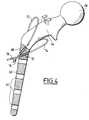
- the prosthesis with external cortical support shown in FIG. 4comprises a plate 60 provided with holes 62 for receiving screws for fixing to the femur.
- the plate 60is extended by a portion 64 forming a neck ending in a ball 66 forming the head of the prosthesis intended to be received in the acetabular cavity of the iliac bone.
- inclined holes 68.70are provided for receiving flexible links 72.74 formed by cables, for replacing and holding the large one respectively trochanter and lesser trochanter in a manner already described with reference to Figures 1 and 2.
- the inventionhas been described as being applicable to nail-plates, screw-plates and prostheses with external cortical support.
- This clampwhich bears the general reference 80 comprises two branches 81, 82 articulated together by a hinge pin 83 and assembled in a removable manner, for example by means of a wing nut 84 screwed onto a threaded end of the axis d hinge 83.
- the jaws 85,86 of the branches 81,82each have a cable pass tube 87,88 curved at its end opposite the articulation of the branches.
- One of the cable passage tubes 87comprises a male tubular end piece 89 intended to be engaged in the curved end of the other cable passage tube 88 to form a continuous channel allowing the passage without obstacle of a cable such as the cable 32 when the ends of the jaws 87.88 of the forceps are engaged in the tissues of the iliac psoas muscle 7 secured to the tuberosity of the small trochanter 4 represented as the rest of the femur joint and the prosthesis element 1, dashed line in Figure 5.
- the handles 91, 92 of the branches 81, 82 of the cable-passing clampare joined together by a rod 93 articulated on one of the handles 92 and engaged in a slot 94 formed in the other handle 91 of the clamp.
- the rod 93is threaded and a clamping screw 95 is mounted on the free end of the rod 93 outside of the handle 94. Inside the handle 91, the rod 93 carries a stop 96 for adjusting the clamping degree of the clamp.
- the replacement or stabilization of the tuberosity of the trochantersis carried out in the following manner.
- the tuberositiesare stabilized lastly after the implantation of the prosthesis element such as the nail plate 1 of FIG. 1.
- This operating timetherefore takes place after the osteosynthesis of the trochanteric fracture by a nail-plate, a screw-plate or the like.
- the small trochanter 4is lowered using the cable 32 then the scale 4a is stabilized using a strapping by means of this cable.
- the scale 4ahas a sufficient vertical extent, it can also be stabilized at its lower part by one of the screws 11 for fixing the nail-plate on the external cortex of the femur 2 (FIG. 6).
- the two handles 91, 92are brought together and therefore their ends of the jaws 85,86 of the forceps so that they pass through the white tendon of the psoas-iliac muscle 7 represented. in dashed line.
- the lesser trochanter 4is in the state shown in FIG. 6.
- the lesser trochanterunderwent a lateral displacement during the fracture due to the retraction of the psoas-iliac muscle.
- a metal washer 100 and a thrust ballare engaged on the anterior strand of the cable. 101 for the washer.
- the ball 101is fixed to the cable 32.
- the washer 100is then gently moved in contact with the trochanter 4 by exerting traction on the rear strand of the cable 32.
- the two strands of the cable 32are then passed through the passages 22 drilled in the plate 8 of the nail plate.
- the assemblyis stabilized using the two balls such as the balls 36 (Fig. 1) crimped onto the cable 32.
- the small trochanter 4has been stabilized with two straps, one consisting of cable 32 and the other, of an additional cable 102 put in place and immobilized under the same conditions as cable 32 and passing through orifices 104 formed in the plate 8 below the passages 22 for the cable 32.
- the stabilization of the greater trochanteris carried out according to the invention using the cable-passing pliers, in the same way as that of the lesser trochanter, by passing the posterior branch of the cable-passing pliers forward or to the inside of the white tendon of the gluteus maxims.
- FIG. 9schematically represents a finished assembly of a nail-plate 1 on the invention, the large trochanter 3 being reduced using the cable 26, immobilized relative to the plate 8 by the crimped balls 30 (FIG. 1 ) and cut to the desired length, while the little trochanter 4 is reduced using cable 32.
Landscapes
- Health & Medical Sciences (AREA)
- Orthopedic Medicine & Surgery (AREA)
- Life Sciences & Earth Sciences (AREA)
- Animal Behavior & Ethology (AREA)
- Veterinary Medicine (AREA)
- Public Health (AREA)
- Surgery (AREA)
- Engineering & Computer Science (AREA)
- Biomedical Technology (AREA)
- Heart & Thoracic Surgery (AREA)
- General Health & Medical Sciences (AREA)
- Molecular Biology (AREA)
- Medical Informatics (AREA)
- Nuclear Medicine, Radiotherapy & Molecular Imaging (AREA)
- Neurology (AREA)
- Cardiology (AREA)
- Oral & Maxillofacial Surgery (AREA)
- Transplantation (AREA)
- Vascular Medicine (AREA)
- Prostheses (AREA)
Abstract
Description
Translated fromFrenchLa présente invention est relative aux éléments de prothèse de hanche et se rapporte plus particulièrement aux éléments de prothèse à appui cortical externe destinés à réduire et stabiliser des fractures trochantériennes d'extrémité supérieure du fémur.The present invention relates to hip prosthesis elements and relates more particularly to prosthesis elements with external cortical support intended to reduce and stabilize trochanteric fractures of the upper end of the femur.
Parmi les éléments de prothèses à appui cortical externe, on peut citer:
- les clous plaques
- les vis plaques qu'elles soient dynamiques ou stabilisées
- les lames plaques
- certaines prothèses de hanche.
- the plate nails
- plate screws whether dynamic or stabilized
- the plates blades
- certain hip prostheses.
Tous ces éléments de prothèses ont pour point commun, de comporter une plaque destinée à être fixée à l'aide de vis à l'extérieur du fémur fracturé, cette plaque étant prolongée en direction de la tête du fémur par un clou, une vis, une plaque ou une portion de sphère.All of these prosthetic elements have in common, to include a plate intended to be fixed using screws outside the fractured femur, this plate being extended towards the head of the femur by a nail, a screw, a plate or a portion of a sphere.
Les fractures du col du fémur se produisent dans un grand nombre de cas chez des sujets âgés, en particulier chez les femmes souffrant d'ostéoporose.Fractures of the neck of the femur occur in a large number of cases in elderly people, especially in women with osteoporosis.
L'ostéoporose provoque dans la région du col du fémur, une destruction de la masse osseuse au point qu'il ne peut rester que 5% de cette masse osseuse dans cette région.Osteoporosis causes destruction of the bone mass in the region of the neck of the femur to the point that only 5% of this bone mass can remain in this region.
Il s'ensuit que dans la région du col du fémur, l'os devient creux de sorte que s'il y a fracture, les parois de la cavité formée par disparition du tissu osseux présentent une résistance mécanique dans certains cas insuffisante pour recevoir des vis ou des clous de la plaque de l'élément de prothèse.It follows that in the region of the neck of the femur, the bone becomes hollow so that if there is a fracture, the walls of the cavity formed by disappearance of the bone tissue have a mechanical resistance in some cases insufficient to receive prosthesis element plate screws or nails.
Le problème qui se pose alors pour le chirurgien est de deux natures :
- a) il faut combler la cavité formée par la disparition du tissu osseux, à l'aide d'un matériau biologiquement acceptable par le milieu dans lequel il est implanté;
- b) il faut permettre au patient de retrouver après la pose d'une prothèse, une autonomie pratiquement normale dans un délai le plus court possible.
- a) it is necessary to fill the cavity formed by the disappearance of the bone tissue, using a material biologically acceptable by the medium in which it is implanted;
- b) it is necessary to allow the patient to regain after the fitting of a prosthesis, a practically normal autonomy in the shortest possible time.
La diaphyse fémorale comporte deux saillies osseuses ayant un rôle essentiel pour le fonctionnement de l'articulation de la hanche.The femoral shaft has two bony projections that play an essential role in the functioning of the hip joint.
Il s'agit du grand trochanter et du petit trochanter auxquels sont respectivement reliés les extrémités du muscle moyen-fessier et du muscle psoas iliaque.These are the greater trochanter and the lesser trochanter to which the ends of the middle gluteus muscle and the iliac psoas muscle are respectively connected.
Dans certaines fractures dites trochantériennes, le grand trochanter, le petit trochanter et quelquefois les deux, se détachent de la diaphyse et sont entraînés par les muscles moyen-fessier auxquels ils sont normalement reliés.In certain so-called trochanteric fractures, the greater trochanter, the lesser trochanter and sometimes both, detach from the shaft and are driven by the mid-gluteal muscles to which they are normally connected.
Lors du traitement de fractures de ce type, on s'intéressait jusqu'à présent à la stabilisation du fragment principal et on négligeait les grosses tubérosités telles que les trochanters dont la remise en place est pourtant essentielle pour permettre au patient de retrouver rapidement sa mobilité et de ce fait, son autonomie de mouvements.When treating fractures of this type, we have so far been interested in the stabilization of the main fragment and we neglected large tuberosities such as the trochanters, whose replacement is essential to allow the patient to quickly regain his mobility and therefore, its autonomy of movement.
L'invention vise à créer un élément de prothèse qui tout en étant d'une construction très voisine de celle des éléments de prothèses classiques permette d'améliorer considérablement le traitement des fractures trochantériennes.The invention aims to create a prosthesis element which, while being very similar in construction to that of conventional prosthesis elements, makes it possible to considerably improve the treatment of trochanteric fractures.
Elle a donc pour objet un élément de prothèse de la hanche, comprenant un corps destiné à être fixé au fémur et un élément cervical prolongeant le corps et faisant avec celui-ci un angle prédéterminé d'orientation vers la tête du fémur, caractérisé en ce qu'il comporte au moins un lien en forme de boucle de remise en place et de maintien du trochanter fracturé correspondant, les extrémités du lien traversant des orifices ménagés dans le corps de l'élément de prothèse et portant des butées d'immobilisation par rapport audit corps.It therefore relates to a hip prosthesis element, comprising a body intended to be fixed to the femur and a cervical element extending the body and forming with it a predetermined angle of orientation towards the head of the femur, characterized in that that it comprises at least one link in the form of a loop for replacing and holding the corresponding fractured trochanter, the ends of the link passing through orifices made in the body of the prosthesis element and carrying immobilization stops relative to said body.
L'invention sera mieux comprise à l'aide de la description qui va suivre, donnée uniquement à titre d'exemple et faite en se référant aux dessins annexés, sur lesquels :
- la Fig.1 est une vue schématique en perspective d'une articulation de la hanche dans laquelle est monté un élément de prothèse suivant l'invention en forme de clou plaque à appui cortical externe, muni de liens en forme de boucles de remise en place et de maintien du grand trochanter et du petit trochanter suivant l'invention;
- la Fig.2 est une vue en perspective à plus grande échelle montrant un détail de l'élément de prothèse de la figure 1;
- la Fig.3 est une vue en perspective d'un élément de prothèse en forme de vis-plaque suivant l'invention;
- la Fig.4 est une vue en perspective et en coupe partielle d'une prothèse à appui cortical externe suivant l'invention;
- la Fig.5 est une vue en perspective d'une pince passe-câble destinée à la mise en place de liens de remise en place et de maintien des trochanters; et
- les Figs.6 à 9 sont des vues schématiques représentant le procédé de stabilisation des tubérosités trochantériennes mettant en oeuvre un élément de prothèse suivant l'invention.
- Fig.1 is a schematic perspective view of a hip joint in which is mounted a prosthesis element according to the invention in the form of a nail plate with external cortical support, provided with links in the form of resetting loops and maintaining the greater trochanter and the lesser trochanter according to the invention;
- Fig.2 is a perspective view on a larger scale showing a detail of the prosthesis element of Figure 1;
- Fig.3 is a perspective view of a prosthesis element in the form of a screw-plate according to the invention;
- Fig.4 is a perspective view in partial section of a prosthesis with external cortical support according to the invention;
- Fig.5 is a perspective view of a cable clamp for the establishment of replacement links and holding the trochanters; and
- Figs. 6 to 9 are schematic views showing the process for stabilizing the trochanteric tuberosities using a prosthesis element according to the invention.
Sur la figure 1, on a représenté un élément de prothèse suivant l'invention constitué par un clou-plaque désigné par le numéro de référence 1 monté dans un fémur 2 dont le grand trochanter 3 et le petit trochanter 4 sont fracturés et sont détachés de la diaphyse 5 sous l'effet de la rétraction du muscle moyen-fessier 6 et du muscle psoas iliaque 7 auxquels ils sont respectivement fixés.In Figure 1, there is shown a prosthesis element according to the invention consisting of a nail plate designated by the
Le clou-plaque 1 comporte un corps ou plaque 8 d'appui cortical externe appliqué contre la face externe de paroi latérale du fémur 2 et pourvu de trous 10 dans lesquels sont engagées des vis de fixation 11 de la plaque 8 au fémur, matérialisées par leurs axes.The nail-
A son extrémité supérieure, la plaque 8 est prolongée par une tige ou clou 12 engagée dans le col 14 et dans la tête 16 du fémur.At its upper end, the
Le clou 12 fait avec la plaque 8, un angle d'une valeur telle qu'il est dirigé à peu près vers le centre de la tête du fémur 18. Cette valeur peut varier de 5° en 5° de 110° à 150°.The
Le clou-plaque 1 est pourvu dans la région de la jonction du clou 12 avec la plaque 8 de perçages ou orifices 20,22 ménagés dans les bords longitudinaux opposés 24 de la plaque.The nail-
Dans les deux perçages 20 est engagé un lien souple et résistant, par exemple un câble d'acier 26, qui forme une boucle 28 passant dans l'extrémité du muscle fessier, derrière la tubérosité du grand trochanter fracturé 3 et destiné à la remise en place et au maintien du grand trochanter à peu près à son emplacement initial sur la diaphyse 5.In the two
Le câble peut également être réalisé en polymère bio-compatible, ou en matériau bio-résorbable.The cable can also be made of bio-compatible polymer, or of bio-absorbable material.
Le câble 26 est d'abord passé dans un outil approprié dont un exemple sera décrit par la suite, puis dans le tendon du muscle moyen-fessier 6 au-dessus du grand trochanter.The
L'outil est ensuite retiré, le câble restant en place. Le câble est alors inséré dans les perçages 20 du clou-plaque.The tool is then removed, the cable remaining in place. The cable is then inserted into the
Le chirurgien exerce alors une traction sur les deux extrémités du câble 26 de manière à déplacer la boucle 26 ainsi formée et à ramener le grand trochanter 3 à peu près dans sa position correcte par rapport à la diaphyse 5.The surgeon then exerts traction on the two ends of the
Cette position étant atteinte, les extrémités du câble 26 reçoivent par sertissage des éléments de butée tels que des billes 30 de section plus importante que celle des perçages 20 correspondants et les tronçons d'extrémité du câble 26 s'étendant au-delà des billes de butée sont sectionnés.This position having been reached, the ends of the
Les orientations des orifices ou perçages 20 sont déterminées afin de donner au câble 26 l'orientation la plus favorable possible pour lui permettre d'atteindre le grand trochanter 3 qui s'est détaché de la diaphyse et qui est porté par le muscle moyen-fessier 6 rétracté.The orientations of the orifices or
La remise en place du petit trochanter 4 est assurée de façon analogue à l'aide du câble 32 qui est successivement engagé dans le passe-câble mis en place et qui est passé au-dessus du petit trochanter fracturé 4.The replacement of the
Après avoir retiré le passe-câble, on engage le câble dans les perçages 22 de la plaque 8.After removing the cable gland, the cable is engaged in the
Par traction sur la boucle 34 constituée par le câble 32, le petit trochanter 4 est remis en place et les deux brins du câble 32 situés au-delà des perçages 22 par rapport à la boucle 34, sont munis par sertissage de butées 36 en forme de billes et leurs extrémités s'étendant au-delà de ces butées sont sectionnées.By pulling on the
Les orientations des orifices 22 sont également déterminées afin de donner au câble 32 l'orientation la plus favorable possible pour lui permettre d'atteindre le petit trochanter 4.The orientations of the
Ainsi, le grand trochanter 3 et le petit trochanter 4 se trouvent dans des conditions optimales pour se ressouder à la diaphyse.Thus, the
La figure 2 montre clairement les orientations des perçages 20 et 22, ménagées dans les bords de la plaque 8 du clou-plaque de la figure 1.FIG. 2 clearly shows the orientations of the
La figure 3 est une vue en perspective d'une vis-plaque suivant l'invention.Figure 3 is a perspective view of a screw-plate according to the invention.
Cette vis plaque est en tous points semblable au clou-plaque représenté aux figures 1 et 2 à l'exception du fait qu'elle comporte une vis 38 au lieu du clou 12.This plate screw is in all respects similar to the nail-plate shown in FIGS. 1 and 2 except that it includes a
En ce qui concerne les liens souples 40 et 42 de remise en place et de maintien du grand trochanter et du petit trochanter, ils sont disposés par rapport à la plaque 44 de la vis-plaque de la même façon que les liens 26,32 correspondants que comporte le clou-plaque décrit en référence aux figures 1 et 2. Ils traversent la plaque 44 par des orifices 46,47 respectifs.As regards the
Des butées en forme de billes 48,50 sont associées aux extrémités des liens 40,42 réalisés sous forme de câbles de la façon décrite en référence aux figures 1 et 2.Ball-shaped stops 48.50 are associated with the ends of the links 40.42 produced in the form of cables as described with reference to FIGS. 1 and 2.
La prothèse à appui cortical externe représentée à la figure 4 comporte une plaque 60 pourvue de trous 62 de réception de vis de fixation au fémur.The prosthesis with external cortical support shown in FIG. 4 comprises a
La plaque 60 est prolongée par une partie 64 formant col terminée par une boule 66 formant la tête de la prothèse destinée à être reçue dans la cavité cotyloïde de l'os iliaque.The
Dans la partie de la jonction de la plaque 60 et de l'élément formant col 64, sont ménagés des perçages inclinés 68,70 de réception de liens souples 72,74 formés par des câbles, de remise en place et de maintien respectivement du grand trochanter et du petit trochanter d'une manière déjà décrite en référence aux figures 1 et 2.In the part of the junction of the
Aux extrémités libres des câbles 72 et 74 sont montées des butées respectives 76,78 de section supérieure à celle des perçages 68,70 et destinées à immobiliser les câbles 72,74 correspondants par sertissage sur ceux-ci après qu'ils aient été placés par le chirurgien dans leurs positions de maintien en place des trochanters.At the free ends of the
L'invention a été décrite comme étant applicable aux clous-plaques, aux vis-plaques et aux prothèses à appui cortical externe.The invention has been described as being applicable to nail-plates, screw-plates and prostheses with external cortical support.
Elle est également applicable aux lames-plaques.It is also applicable to plate slides.
Sur la figure 5, on a représenté en perspective une pince passe-câble destinée à permettre la mise en place des câbles ou liens de remise en place et de maintien des trochanters fracturés.In Figure 5, there is shown in perspective a cable pass clamp intended to allow the establishment of cables or links for replacing and holding broken trochanters.
Cette pince qui porte la référence générale 80 comporte deux branches 81,82 articulées entre elles par un axe d'articulation 83 et assemblées de façon démontable par exemple au moyen d'un écrou à oreilles 84 vissé sur une extrémité filetée de l'axe d'articulation 83.This clamp which bears the
Les mâchoires 85,86 des branches 81,82 comportent chacune un tube passe-câble 87,88 recourbé à son extrémité opposée à l'articulation des branches.The
L'un des tubes passe-câble 87 comporte un embout tubulaire mâle 89 destiné à être engagé dans l'extrémité recourbée de l'autre tube passe-câble 88 pour former un canal continu permettant le passage sans obstacle d'un câble tel que le câble 32 lorsque les extrémités des mâchoires 87,88 de la pince sont engagées dans les tissus du muscle psoas iliaque 7 solidaire de la tubérosité du petit trochanter 4 représenté comme le reste de l'articulation du fémur et l'élément de prothèse 1, en trait mixte sur la figure 5.One of the
Les poignées 91,92 des branches 81,82 de la pince passe-câble sont réunies entre elles par une tige 93 articulée sur l'une des poignées 92 et engagée dans une fente 94 ménagée dans l'autre poignée 91 de la pince.The
La tige 93 est filetée et une vis de serrage 95 est montée sur l'extrémité libre de la tige 93 à l'extérieur de la poignée 94. A l'intérieur de la poignée 91, la tige 93 porte une butée 96 de réglage du degré de serrage de la pince.The
La remise en place ou stabilisation des tubérosités des trochanters est réalisée da la manière suivante.The replacement or stabilization of the tuberosity of the trochanters is carried out in the following manner.
Les tubérosités sont stabilisées en dernier lieu après la mise en place de l'élément de prothèse tel que le clou-plaque 1 de la figure 1.The tuberosities are stabilized lastly after the implantation of the prosthesis element such as the
Ce temps opératoire se déroule donc après l'ostéosynthèse de la fracture trochantérienne par un clou-plaque, une vis-plaque ou autre.This operating time therefore takes place after the osteosynthesis of the trochanteric fracture by a nail-plate, a screw-plate or the like.
Il peut être nécessaire de stabiliser le petit trochanter dans trois cas.
- a) le petit trochanter est resté en place mais il existe un trait de fracture partiel ou total, habituellement vertical qui isole le petit trochanter du fût diaphysaire, ce qui entraîne un risque de déplacement secondaire du petit trochanter.
- b) le petit trochanter est détaché de la corticale et prolongé vers le bas par une écaille de taille variable.
- a) the little trochanter has remained in place but there is a partial or total fracture line, usually vertical, which isolates the little trochanter from the diaphyseal shaft, which leads to a risk of secondary displacement of the little trochanter.
- b) the lesser trochanter is detached from the cortex and extended downwards by a scale of variable size.
Cette situation est clairement représentée à la figure 1 sur laquelle on voit le petit trochanter 4 détaché de la corticale et pourvu d'une écaille 4a.This situation is clearly shown in Figure 1 in which we see the
Comme représenté sur le schéma de la figure 6, le petit trochanter 4 est abaissé à l'aide du câble 32 puis l'écaille 4a est stabilisée à l'aide d'un cerclage au moyen de ce câble.As shown in the diagram in FIG. 6, the
Si l'écaille 4a a une étendue verticale suffisante, elle peut également être stabilisée à sa partie inférieure par une des vis 11 de fixation du clou-plaque sur la corticale externe du fémur 2 (figure 6).If the
Une stabilisation par cerclage analogue à celle de la figure 6 est également réalisée pour stabiliser un trochanter en place, mais il y a un risque de déplacement secondaire du fait de l'existence d'un trait de fracture.
- c) le petit trochanter est détaché et est venu se placer sous le col, contre le pôle inférieur de la tête fémorale.
- c) the lesser trochanter is detached and has come to be placed under the neck, against the lower pole of the femoral head.
Il est en outre parfois fracturé.It is also sometimes fractured.
En vue de la stabilisation du petit trochanter se trouvant dans cet état, on utilise la pince passe-câble représentée à la figure 5 de la façon suivante :
- on fait d'abord passer la branche antérieure 81 de la pince en avant du col, au-dessus du
petit trochanter 4, - on fait ensuite passer la branche postérieure 82 de la pince en arrière du col, au-dessus du
petit trochanter 4, - on solidarise les
branches 81 et 82 au moyen de l'axe d'articulation 83 et de l'écrou 84.
- first pass the
anterior branch 81 of the forceps in front of the neck, above thelittle trochanter 4, - the
posterior branch 82 of the forceps is then passed behind the neck, above thesmall trochanter 4, - the
branches hinge pin 83 and thenut 84.
A l'aide de l'écrou de serrage 95, on rapproche les deux poignées 91, 92 et de ce fait, leurs extrémités des mâchoires 85,86 de la pince afin qu'elles traversent le tendon blanc du muscle psoas-iliaque 7 représenté en trait mixte.Using the tightening
L'embout tubulaire mâle 89 du tube passe-câble 87 s'engage alors dans l'extrémité du tube passe-câble 88 et établit un canal continu pour le passage d'un câble.
- on fait passer le câble 32 dans le conduit ainsi constitué,
- on sépare les deux
branches - on retire successivement la branche antérieure 81 et la branche postérieure 82 de la pince en maintenant le câble 90 en place,
- on obtient alors la situation représentée à la figure 1 dans laquelle le câble 32 est engagé dans le muscle psoas-iliaque derrière le
petit trochanter 4 et ses extrémités libres traversent laplaque 8 par les perçages 22.
- the
cable 32 is passed through the conduit thus formed, - the two
branches nut 84 and removing therod 93 associated with the clampingnut 95 from theslot 94 of thehandle 91 of the clamp; - the
front branch 81 and therear branch 82 are removed successively from the clamp while holding the cable 90 in place, - the situation represented in FIG. 1 is then obtained in which the
cable 32 is engaged in the psoas-iliac muscle behind thesmall trochanter 4 and its free ends pass through theplate 8 through theholes 22.
Pour réduire le petit trochanter, on combine deux manoeuvres :
- on abaisse le petit trochanter lorsqu'il est en position haute,
- on l'amène en arrière puisqu'il est déplacé en avant et en dedans.
- we lower the little trochanter when it is in the high position,
- it is brought back since it is moved in and out.
Cette réduction retend également la capsule antérieure.This reduction also tightens the anterior capsule.
Une fois réduit, le petit trochanter 4 se trouve dans l'état représenté à la figure 6.Once reduced, the
Comme représenté à la figure 7, le petit trochanter a subi lors de la fracture, un déplacement latéral sous l'effet de la rétraction du muscle psoas-iliaque.As shown in Figure 7, the lesser trochanter underwent a lateral displacement during the fracture due to the retraction of the psoas-iliac muscle.
En l'occurrence, le déplacement latéral a eu lieu vers l'avant du col.In this case, the lateral displacement took place towards the front of the cervix.
Afin de repositionner correctement le petit trochanter 4, après avoir fait passer le câble 32 dans le muscle psoas-iliaque comme décrit précédemment en référence à la figure 5, on engage sur le brin antérieur du câble, une rondelle métallique 100 et une bille de butée 101 pour la rondelle.In order to correctly reposition the
A l'aide d'une pince à sertir, on fixe la bille 101 sur le câble 32.Using a crimping tool, the
On déplace alors doucement la rondelle 100 au contact du trochanter 4 en exerçant une traction sur le brin postérieur du câble 32.The
On fait ensuite passer les deux brins du câble 32 dans les passages 22 percés dans la plaque 8 du clou-plaque.The two strands of the
On exerce un traction sur les deux brins du câble pour amener le petit trochanter à sa place.One exerts a traction on the two strands of the cable to bring the little trochanter in its place.
On stabilise l'ensemble à l'aide des deux billes telles que les billes 36 (Fig.1) serties sur le câble 32.The assembly is stabilized using the two balls such as the balls 36 (Fig. 1) crimped onto the
En fonction de la longueur de l'écaille interne 4a, on peut être amené à stabiliser le petit trochanter avec deux cerclages ou plus.Depending on the length of the
Sur la figure 8, le petit trochanter 4 a été stabilisé avec deux cerclages constitués l'un du câble 32 et l'autre, d'un câble supplémentaire 102 mis en place et immobilisé dans les mêmes conditions que le câble 32 et traversant des orifices 104 ménagés dans la plaque 8 au-dessous des passages 22 pour le câble 32.In FIG. 8, the
La stabilisation du grand trochanter est réalisée selon l'invention à l'aide de la pince passe-câble, de la même manière que celle du petit trochanter, en faisant passer la branche postérieure de la pince passe-câble en avant ou à l'intérieur du tendon blanc du moyen-fessier.The stabilization of the greater trochanter is carried out according to the invention using the cable-passing pliers, in the same way as that of the lesser trochanter, by passing the posterior branch of the cable-passing pliers forward or to the inside of the white tendon of the gluteus medius.
La figure 9 représente schématiquement un montage terminé d'un clou-plaque 1 sur l'invention, le grand trochanter 3 étant réduit à l'aide du câble 26, immobilisé par rapport à la plaque 8 par les billes serties 30 (Fig.1) et coupé à la longueur voulue, tandis que le petit trochanter 4 est réduit à l'aide du câble 32.FIG. 9 schematically represents a finished assembly of a nail-
On voit que grâce à l'agencement qui vient d'être décrit, on parvient à réduire des fractures trochantériennes en remettant en place les trochanters, ce qui permet au patient de recouvrer rapidement sa stabilité lors de l'appui monopodal et sa force musculaire lors de la montée ou de la descente des escaliers.We see that thanks to the arrangement which has just been described, we manage to reduce trochanteric fractures by replacing the trochanters, which allows the patient to quickly recover its stability during monopodal support and its muscular strength during climbing or descending stairs.
Claims (8)
Translated fromFrenchApplications Claiming Priority (2)
| Application Number | Priority Date | Filing Date | Title |
|---|---|---|---|
| FR9805622AFR2778090B1 (en) | 1998-05-04 | 1998-05-04 | HIP PROSTHESIS ELEMENT WITH EXTERNAL CORTICAL SUPPORT FOR TROCHANTERIAL FRACTURES AND CABLE GRIPPER FOR THE PLACEMENT OF SUCH AN ELEMENT |
| FR9805622 | 1998-05-04 |
Publications (1)
| Publication Number | Publication Date |
|---|---|
| EP0955013A1true EP0955013A1 (en) | 1999-11-10 |
Family
ID=9526001
Family Applications (1)
| Application Number | Title | Priority Date | Filing Date |
|---|---|---|---|
| EP99401087AWithdrawnEP0955013A1 (en) | 1998-05-04 | 1999-05-04 | Elément destiné à stabiliser des fractures trochantériennes et pince passe-cáble pour sa mise en place |
Country Status (2)
| Country | Link |
|---|---|
| EP (1) | EP0955013A1 (en) |
| FR (1) | FR2778090B1 (en) |
Cited By (12)
| Publication number | Priority date | Publication date | Assignee | Title |
|---|---|---|---|---|
| EP1464294A1 (en) | 2003-04-02 | 2004-10-06 | Benoist Girard Sas | Greater trochanter re-attachment device |
| EP1764053A1 (en)* | 2005-09-19 | 2007-03-21 | DePuy Products, Inc. | Bone fixation plate with complex suture anchor locations |
| FR2892922A1 (en)* | 2005-11-08 | 2007-05-11 | Ortho I D Sarl | Trochanteric implant for forming femoral prosthesis, has hooks that allow fixation of femoral tuberosity part on implant by using encircling devices and with pin and throat respectively, where one of hooks enclose encircling devices |
| EP1709921A3 (en)* | 2005-04-04 | 2009-04-22 | Arthrex, Inc. | Bone plate with suture loops |
| EP1887948A4 (en)* | 2005-06-02 | 2011-03-02 | Medicinelodge Inc | Bone implants with integrated line locks |
| US8142434B2 (en) | 2007-10-17 | 2012-03-27 | Stryker Trauma Gmbh | Cam-locking of cable for fracture plate |
| WO2014062145A1 (en)* | 2012-10-19 | 2014-04-24 | Spi̇namer Sağlik Ürünleri̇ Sanayi̇ Ve Teknoloji̇ Li̇mi̇ted Şi̇rketi̇ | Ortovia minimally invasive hip plate |
| US8764809B2 (en) | 2006-08-15 | 2014-07-01 | Swissmedtechsolutions Ag | Trochanter retention plate |
| US9265498B2 (en) | 2003-06-11 | 2016-02-23 | Imds Llc | Compact line locks and methods |
| US9526543B2 (en) | 2004-11-10 | 2016-12-27 | Biomet C.V. | Modular fracture fixation system |
| US10675072B2 (en) | 2018-01-02 | 2020-06-09 | Acumed Llc | Bone fixation with a plate and a coupler connected by flexible members |
| US10820935B2 (en) | 2017-02-03 | 2020-11-03 | Stryker European Holdings I, Llc | Tensioning cable locking device |
Families Citing this family (1)
| Publication number | Priority date | Publication date | Assignee | Title |
|---|---|---|---|---|
| CN106618719B (en)* | 2017-01-11 | 2023-04-18 | 海口市人民医院 | Hollow lag screw guide pin aiming fixer for reduction through posterior femoral lesser tuberosity |
Citations (7)
| Publication number | Priority date | Publication date | Assignee | Title |
|---|---|---|---|---|
| US2181746A (en)* | 1939-02-04 | 1939-11-28 | John R Siebrandt | Combination bone clamp and adjustable drill guide |
| DE3132543A1 (en)* | 1980-11-25 | 1982-06-03 | Gebrüder Sulzer AG, 8401 Winterthur | Femoral head prosthesis |
| FR2589353A1 (en)* | 1985-07-10 | 1987-05-07 | Cirotteau Yves | Total hip prosthesis with external cortical pressure |
| FR2614781A1 (en)* | 1987-05-05 | 1988-11-10 | Galline Yves | ATTACHMENT DEVICE AND TOOLS FOR ITS PLACEMENT, IN PARTICULAR TO ATTACH THE BIG TROCHANTER TO THE FEMUR |
| GB2214814A (en)* | 1988-01-28 | 1989-09-13 | Bio Medical Eng | Surgical apparatus for guiding a wire or suture in a loop |
| WO1989010730A1 (en)* | 1988-05-11 | 1989-11-16 | Dall Desmond Meiring | Hip joint femoral prosthesis |
| WO1993008771A1 (en)* | 1991-10-30 | 1993-05-13 | Depuy International Limited | A femoral prosthesis |
- 1998
- 1998-05-04FRFR9805622Apatent/FR2778090B1/ennot_activeExpired - Fee Related
- 1999
- 1999-05-04EPEP99401087Apatent/EP0955013A1/ennot_activeWithdrawn
Patent Citations (7)
| Publication number | Priority date | Publication date | Assignee | Title |
|---|---|---|---|---|
| US2181746A (en)* | 1939-02-04 | 1939-11-28 | John R Siebrandt | Combination bone clamp and adjustable drill guide |
| DE3132543A1 (en)* | 1980-11-25 | 1982-06-03 | Gebrüder Sulzer AG, 8401 Winterthur | Femoral head prosthesis |
| FR2589353A1 (en)* | 1985-07-10 | 1987-05-07 | Cirotteau Yves | Total hip prosthesis with external cortical pressure |
| FR2614781A1 (en)* | 1987-05-05 | 1988-11-10 | Galline Yves | ATTACHMENT DEVICE AND TOOLS FOR ITS PLACEMENT, IN PARTICULAR TO ATTACH THE BIG TROCHANTER TO THE FEMUR |
| GB2214814A (en)* | 1988-01-28 | 1989-09-13 | Bio Medical Eng | Surgical apparatus for guiding a wire or suture in a loop |
| WO1989010730A1 (en)* | 1988-05-11 | 1989-11-16 | Dall Desmond Meiring | Hip joint femoral prosthesis |
| WO1993008771A1 (en)* | 1991-10-30 | 1993-05-13 | Depuy International Limited | A femoral prosthesis |
Cited By (18)
| Publication number | Priority date | Publication date | Assignee | Title |
|---|---|---|---|---|
| US7611513B2 (en) | 2003-04-02 | 2009-11-03 | Benoist Girard Sas | Greater trochanteric re-attachment device |
| EP1464294A1 (en) | 2003-04-02 | 2004-10-06 | Benoist Girard Sas | Greater trochanter re-attachment device |
| US9265498B2 (en) | 2003-06-11 | 2016-02-23 | Imds Llc | Compact line locks and methods |
| US9913671B2 (en) | 2004-11-10 | 2018-03-13 | Biomet C.V. | Modular fracture fixation system |
| US9526543B2 (en) | 2004-11-10 | 2016-12-27 | Biomet C.V. | Modular fracture fixation system |
| EP1709921A3 (en)* | 2005-04-04 | 2009-04-22 | Arthrex, Inc. | Bone plate with suture loops |
| US8579944B2 (en) | 2005-04-04 | 2013-11-12 | Arthrex, Inc. | Bone plate with suture loops |
| EP1887948A4 (en)* | 2005-06-02 | 2011-03-02 | Medicinelodge Inc | Bone implants with integrated line locks |
| US7604657B2 (en) | 2005-09-19 | 2009-10-20 | Depuy Products, Inc. | Bone fixation plate with complex suture anchor locations |
| JP2007083047A (en)* | 2005-09-19 | 2007-04-05 | Depuy Products Inc | Bone fixation plate with complex suture anchor location |
| EP1764053A1 (en)* | 2005-09-19 | 2007-03-21 | DePuy Products, Inc. | Bone fixation plate with complex suture anchor locations |
| FR2892922A1 (en)* | 2005-11-08 | 2007-05-11 | Ortho I D Sarl | Trochanteric implant for forming femoral prosthesis, has hooks that allow fixation of femoral tuberosity part on implant by using encircling devices and with pin and throat respectively, where one of hooks enclose encircling devices |
| US8764809B2 (en) | 2006-08-15 | 2014-07-01 | Swissmedtechsolutions Ag | Trochanter retention plate |
| US10463409B2 (en) | 2006-09-28 | 2019-11-05 | Biomet C.V. | Modular fracture fixation system |
| US8142434B2 (en) | 2007-10-17 | 2012-03-27 | Stryker Trauma Gmbh | Cam-locking of cable for fracture plate |
| WO2014062145A1 (en)* | 2012-10-19 | 2014-04-24 | Spi̇namer Sağlik Ürünleri̇ Sanayi̇ Ve Teknoloji̇ Li̇mi̇ted Şi̇rketi̇ | Ortovia minimally invasive hip plate |
| US10820935B2 (en) | 2017-02-03 | 2020-11-03 | Stryker European Holdings I, Llc | Tensioning cable locking device |
| US10675072B2 (en) | 2018-01-02 | 2020-06-09 | Acumed Llc | Bone fixation with a plate and a coupler connected by flexible members |
Also Published As
| Publication number | Publication date |
|---|---|
| FR2778090A1 (en) | 1999-11-05 |
| FR2778090B1 (en) | 2000-10-06 |
Similar Documents
| Publication | Publication Date | Title |
|---|---|---|
| EP1897509B1 (en) | Arthrodesis plate for a metatarsal-phalanges joint | |
| EP1113758B1 (en) | Posterior backbone osteosynthesis device | |
| EP0955013A1 (en) | Elément destiné à stabiliser des fractures trochantériennes et pince passe-cáble pour sa mise en place | |
| FR2651992A1 (en) | Implant for spinal osteosynthesis of the anterior dorsolumbar vertebrae intended for correction of kyphoses | |
| EP0028546B1 (en) | Hip prosthesis | |
| CA2637456C (en) | Surgical implant with extracortical support for a ligament transplant | |
| WO2011083261A1 (en) | Vertebral attachment device | |
| FR2763831A1 (en) | Spinal surgery instrumentation rod | |
| FR2735351A1 (en) | IMPLANT FOR THE SURGICAL TREATMENT OF A VERTEBRAL ISTHUMIC FRACTURE | |
| FR2545350A1 (en) | DEVICE FOR STAMPING THE RACHIS | |
| EP0578807A1 (en) | Osteosynthesis implant assembly and fitting device | |
| AU4343699A (en) | Instrument for the positioning of an implant in the human spine | |
| FR2683712A1 (en) | PROTECTIVE CAP FOR AN OSTEOSYNTHESIS SPINDLE AND ASSEMBLY COMPRISING THIS CAP AS WELL AS AN ORGAN FOR FIXING IT TO THE SPINDLE. | |
| WO1994004086A1 (en) | Osteosynthesis device | |
| FR2504385A3 (en) | DEVICE FOR THE RESTITUTION OF THE FUNCTION OF A MEMBER OF THE HUMAN BODY | |
| FR2677536A1 (en) | Plate for the treatment of a fracture and permitting a ligature | |
| EP1269941A1 (en) | Shoulder prosthesis | |
| FR2684543A1 (en) | Artificial ligament, especially for the ankles | |
| FR2790941A1 (en) | INSTRUMENTATION OF RACHIDIAN OSTEOSYNTHESIS WITH PLATE AND PEDICULAR SCREW OR TRANSVERSE CONNECTOR BETWEEN A VERTEBRAL ROD AND A PEDICULAR SCREW | |
| EP0754014B1 (en) | Centromedullary nailing device, in particular for subcervical fractures of the thigh bone | |
| EP1683501B1 (en) | Device for the osteosynthesis of a shoulder joint | |
| FR2930424A1 (en) | DEVICE FOR REDUCING A FRACTURE BETWEEN THE EPIPHYSARY HEAD AND THE DIAPHYSIS OF A LONG BONE, IN PARTICULAR A PROXIMAL HUMERAL FRACTURE. | |
| FR2804598A1 (en) | DEVICE FOR FIXING AN IMPLANT OR TRANSPLANT FORMING PROSTHETIC LIGAMENT ON BONE | |
| FR2866229A1 (en) | Lumbar cage for patient, has branches with front ends spaced angularly by unscrewing of screw and separation of spacing roller from head, where roller supports free front ends of branches against pressure exerted by vertebral body | |
| EP1967150A1 (en) | Vertebral anchoring device using an intrapedicular nail |
Legal Events
| Date | Code | Title | Description |
|---|---|---|---|
| PUAI | Public reference made under article 153(3) epc to a published international application that has entered the european phase | Free format text:ORIGINAL CODE: 0009012 | |
| AK | Designated contracting states | Kind code of ref document:A1 Designated state(s):CH DE ES FR GB IT LI | |
| AX | Request for extension of the european patent | Free format text:AL;LT;LV;MK;RO;SI | |
| RTI1 | Title (correction) | Free format text:ELEMENT DESTINE A STABILISER DES FRACTURES TROCHANTERIENNES ET PINCE PASSE-CABLE POUR SA MISE EN PLACE | |
| K1C3 | Correction of patent application (complete document) published | Effective date:19991110 | |
| RTI1 | Title (correction) | Free format text:ELEMENT FOR STABILISING TROCHANTERIC FRACTURES AND CABLE-PASSING PLIERS FOR POSITIONING THEREOF | |
| 17P | Request for examination filed | Effective date:20000425 | |
| AKX | Designation fees paid | Free format text:CH DE ES FR GB IT LI | |
| 17Q | First examination report despatched | Effective date:20010813 | |
| GRAG | Despatch of communication of intention to grant | Free format text:ORIGINAL CODE: EPIDOS AGRA | |
| RTI1 | Title (correction) | Free format text:ELEMENT FOR STABILISING TROCHANTERIC FRACTURES | |
| GRAG | Despatch of communication of intention to grant | Free format text:ORIGINAL CODE: EPIDOS AGRA | |
| GRAH | Despatch of communication of intention to grant a patent | Free format text:ORIGINAL CODE: EPIDOS IGRA | |
| STAA | Information on the status of an ep patent application or granted ep patent | Free format text:STATUS: THE APPLICATION HAS BEEN WITHDRAWN | |
| 18W | Application withdrawn | Effective date:20030104 |