EP0953144B1 - Brake judder testing - Google Patents
Brake judder testingDownload PDFInfo
- Publication number
- EP0953144B1 EP0953144B1EP98900580AEP98900580AEP0953144B1EP 0953144 B1EP0953144 B1EP 0953144B1EP 98900580 AEP98900580 AEP 98900580AEP 98900580 AEP98900580 AEP 98900580AEP 0953144 B1EP0953144 B1EP 0953144B1
- Authority
- EP
- European Patent Office
- Prior art keywords
- disc
- pads
- operating means
- pressure
- supply
- Prior art date
- Legal status (The legal status is an assumption and is not a legal conclusion. Google has not performed a legal analysis and makes no representation as to the accuracy of the status listed.)
- Expired - Lifetime
Links
- 238000012360testing methodMethods0.000titleclaimsdescription21
- 239000012530fluidSubstances0.000claimsdescription14
- 238000012544monitoring processMethods0.000claimsdescription10
- 238000006073displacement reactionMethods0.000claimsdescription3
- 238000002955isolationMethods0.000description1
- 239000000463materialSubstances0.000description1
- 238000005259measurementMethods0.000description1
Images
Classifications
- B—PERFORMING OPERATIONS; TRANSPORTING
- B60—VEHICLES IN GENERAL
- B60T—VEHICLE BRAKE CONTROL SYSTEMS OR PARTS THEREOF; BRAKE CONTROL SYSTEMS OR PARTS THEREOF, IN GENERAL; ARRANGEMENT OF BRAKING ELEMENTS ON VEHICLES IN GENERAL; PORTABLE DEVICES FOR PREVENTING UNWANTED MOVEMENT OF VEHICLES; VEHICLE MODIFICATIONS TO FACILITATE COOLING OF BRAKES
- B60T17/00—Component parts, details, or accessories of power brake systems not covered by groups B60T8/00, B60T13/00 or B60T15/00, or presenting other characteristic features
- B60T17/18—Safety devices; Monitoring
- B60T17/22—Devices for monitoring or checking brake systems; Signal devices
- B60T17/221—Procedure or apparatus for checking or keeping in a correct functioning condition of brake systems
- G—PHYSICS
- G01—MEASURING; TESTING
- G01L—MEASURING FORCE, STRESS, TORQUE, WORK, MECHANICAL POWER, MECHANICAL EFFICIENCY, OR FLUID PRESSURE
- G01L5/00—Apparatus for, or methods of, measuring force, work, mechanical power, or torque, specially adapted for specific purposes
- G01L5/28—Apparatus for, or methods of, measuring force, work, mechanical power, or torque, specially adapted for specific purposes for testing brakes
Definitions
- This inventionis concerned with the testing apparatus for disc brakes.
- a disc brakecomprises a disc which rotates with a hub, two brake pads positioned on opposite sides of the disc, and pad moving means operable to cause the pads to be urged against the disc into a "brakes on” condition in which they apply significant braking forces to the disc.
- the pad moving meansis often a calliper mechanism which often comprises a hydraulically-operated piston and cylinder assembly.
- Disc brakesnormally do not provide for the pads to be pulled fully away from the disc after a brake application. Instead, when the pad moving means ceases to urge the pads against the disc, the pads are "knocked" away by the disc into a “brakes off” condition in which the pads are close to the disc but out of contact therewith.
- Brake judderoccurs when a disc has an uneven thickness. Such uneven thickness results from parts of the disc intermittently contacting the pads when the brakes are in the "brakes off” condition. Conventional dynamometers do not control the position of the pads during the "brakes off” condition so that the possibility of disc thickness variation occurring is somewhat random and tests are not reliably repeatable.
- the inventionprovides a disc brake testing apparatus comprising operating means being arranged to operate in use according to a first mode, wherein pad moving means of the disc brake cause the moving means to urge pads of the brake towards the disc thereof, and the operating means urge the pads against the disc with a higher pressure sufficient to cause the pads to maintain constant contact with the disc and apply a significant braking force thereto, characterised in that the operating means is additionally arranged to operate in use according to a second mode, wherein the pads are urged against the disc with a lower pressure selected to cause the pads to make intermittent contact with the disc during each revolution of the disc.
- the padswhen the operating means operates with said lower pressure, the pads do not significantly brake the disc but make intermittent contact therewith (due to run-out, ie axis wobble, or disc thickness variation), thereby simulating, in a controlled and reproducible manner, the conditions which give rise to disc thickness variation.
- Said lower pressurehas to be selected to suit the particular brake but pressures below 1 bar are suitable, eg 0.4 to 0.1 bar. Any disc thickness variation caused can then be measured after the test.
- a testing apparatusmay also comprise monitoring means operable to monitor displacements of the pads, when the operating means operates with said lower pressure.
- monitoring meansmay, for example, detect variations in the pressure applied by the operating means.
- Such monitoring meanscan detect whether intermittent contact is occurring and, hence, whether said lower pressure requires adjustment.
- a testing apparatuscomprises operating means comprising a high pressure fluid supply which is arranged to supply said higher pressure, and a low pressure supply which is arranged to supply said lower pressure.
- operating meanscomprising a high pressure fluid supply which is arranged to supply said higher pressure, and a low pressure supply which is arranged to supply said lower pressure.
- This arrangementavoids constant adjustment of the pressure of a single fluid supply.
- the pressures supplied by the high and low pressure fluid supplieswill be different in different circumstances but, typically, said high pressure supply operates at about 30 bar and the low pressure supply at less than 1 bar, eg about 0.4 bar.
- the operating meansmay be operable to adjust said lower pressure by altering the volume occupied by the fluid.
- the operating meansmay alter said volume by operating a stepper motor or other servo device.
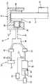
- the drawingis a diagrammatic view of a portion of the illustrative apparatus.
- the illustrative disc brake testing apparatus 10is arranged to test a disc brake 12 which comprises a disc 14 which rotates with a hub 16, two brake pads 18 and 20 positioned on opposite sides of the disc, and pad moving means 22 operable to cause the pads to be urged against the disc.
- the pad moving means 22is in the form of a calliper mechanism which comprises a bridge member 24 mounted for sliding movement in a direction parallel to the axis about which the disc 14 rotates.
- the bridge member 24has the pad 18 mounted directly thereon so that the pad 18 extends parallel to one side surface of the disc 14.
- the bridge member 24defines a cylinder 26 in which a piston 28 is movable.
- the piston 28engages the pad 20 which also extends parallel to a side surface of the disc 14.
- the piston 28is urged out of the cylinder 26 and urges the pad 20 against the disc 14. Movement of the piston 28 also causes sliding of the bridge member 22, in the opposite direction, thereby urging the pad 18 against the disc 14.
- the apparatus 10also comprises operating means 32 operable to operate the pad moving means 22 of the disc brake 12 to cause the moving means to urge the pads 18 and 20 towards the disc 14.
- the operating means 32comprises a high pressure fluid supply 34, a low pressure fluid supply 36, and a manifold 38 which connects the pipe 30 to the supply 34, or to the supply 36.
- An isolation valve 40is located between each of the supplies 34 and 36 and the manifold 38. When the supply 34 is connected to the manifold 38, the supply 36 is isolated therefrom and vice versa.
- the high pressure supply 34comprises a diaphragm cylinder and can supply a pressure of 100 bar but normally operates at about 30 bar.
- the operating means 32is operable to urge the pads 18 and 20 towards the disc 14 with a higher pressure sufficient to cause the pads to maintain constant contact with the disc and apply a significant braking force to the disc 14.
- a pressure indicator 42is associated with the supply 34.
- the low pressure supply 36comprises a cylinder 44, a piston 46 movable in the cylinder 44, a piston rod 48 connected to the piston 46, and a stepper motor 50 operable to move the piston rod 48 and, hence, the piston 46 within the cylinder 44. Operation of the motor 50 moves the piston 46 to determine the pressure of hydraulic fluid in the cylinder 44 and, when the supply 36 is connected to the pipe 30, this determines the pressure in the pipe 30 and the cylinder 26.
- the supply 36can supply a pressure up to 1 bar and normally operates at about 0.4 bar.
- the operating means 32is operable to urge the pads 18 and 20 against 14 the disc with a lower pressure selected to cause the pads to make intermittent contact with the disc 14 during each revolution of the disc, ie the pads rest on the disc until displaced and are returned to rest on the disc again.
- the pads 18 and 20gently rest on the disc 14 unless displaced by pressure from the disc 14 which occurs due to thickness variation, or due to run-out of the disc about its axis of rotation.
- the pads 18 and 20are knocked away from the disc 14, they are gently returned thereto. In practice, this knocking away will flex the seals of the cylinder 26 rather than displacing the piston 28 relative to said seals.
- the apparatus 10also comprises monitoring means 52 operable to monitor displacements of the pads 18 and 20 from the disc 14 when the operating means operates with said lower pressure.
- the monitoringmay be utilised to maintain said lower pressure at a predetermined value or may be utilised to determine whether intermittent contact is occurring.
- the monitoring means 52is a computer which receives feedback of the pressure in the supply 36 from a pressure detector 54.
- the monitoring meansshould detect a pressure variation which, during each revolution of the disc 14, has at least one period of constant pressure (during which the pads are out of contact with the disc) and at least one period of increased pressure (during which the pads contact the disc). If conditions of intermittent contact are not observed, the monitoring means can operate the motor 50 to adjust the volume until intermittent contact conditions are established.
- the operating means 32is operable, in response to variations detected in the pressure of fluid in the low pressure supply 36, to alter the volume occupied by the fluid.
- the disc brake 12is mounted on the apparatus and the stepper motor 50 is used to determine the pressure required in the cylinder 44 to just move the pads 18 and 20 into contact with the disc 14. This pressure is used as said lower pressure. This pressure varies from brake to brake due to such factors as the stiffness of seals.
- the disc 14is then rotated and the moving means 22 is operated to create "brakes on" conditions with the supply 34 connected to the pipe 30, or conditions in which disc thickness variation may occur with the supply 36 connected.
- the monitoring means 52checks that intermittent contact is occurring and operates the motor 50 to re-establish intermittent contact if it ceases, eg due to temperature increases.
Landscapes
- Engineering & Computer Science (AREA)
- Transportation (AREA)
- Mechanical Engineering (AREA)
- Physics & Mathematics (AREA)
- General Physics & Mathematics (AREA)
- Braking Arrangements (AREA)
- Force Measurement Appropriate To Specific Purposes (AREA)
Description
Claims (5)
- A disc brake testing apparatus (10) comprisingoperating means (32) being arranged to operate in use according to a first mode, wherein pad movingmeans (22) of the disc brake (12) cause the movingmeans to urge pads (18, 20) of the brake towards thedisc (14) thereof, and the operating means (32)urge the pads against the disc (14) witha higher pressure sufficient to cause the pads tomaintain constant contact with the disc and apply asignificant braking force thereto,characterised inthat the operating means (32) is additionally arranged to operate in use according to a second mode, whereinthe pads are urged against the disc with alower pressure selected to cause the pads (18, 20) tomake intermittent contact with the disc (14) duringeach revolution of the disc.
- A testing apparatus according to claim 1,characterised inthat the apparatus (10) also comprises monitoringmeans (52) operable to monitor displacements of thepads (18, 20), when the operating means (32) operateswith said lower pressure.
- A testing apparatus according either one of claims 1and 2,characterised in that the apparatus (10)comprises operating means (32) comprising a highpressure fluid supply (34) which is arranged to supplysaid higher pressure, and a low pressure supply (36)which is arranged to supply said lower pressure.
- A testing apparatus according to claim 3,characterised in that the operating means (32) isoperable to adjust said lower pressure by altering thevolume occupied by the fluid.
- A testing apparatus according to claim 4,characterised in that the operating means (32) alters said volume by operating a stepper motor (50) or otherservo device.
Applications Claiming Priority (3)
| Application Number | Priority Date | Filing Date | Title |
|---|---|---|---|
| GB9700584AGB2321090B (en) | 1997-01-14 | 1997-01-14 | Brake testing |
| GB9700584 | 1997-01-14 | ||
| PCT/GB1998/000086WO1998030876A1 (en) | 1997-01-14 | 1998-01-12 | Brake judder testing |
Publications (2)
| Publication Number | Publication Date |
|---|---|
| EP0953144A1 EP0953144A1 (en) | 1999-11-03 |
| EP0953144B1true EP0953144B1 (en) | 2002-08-14 |
Family
ID=10805894
Family Applications (1)
| Application Number | Title | Priority Date | Filing Date |
|---|---|---|---|
| EP98900580AExpired - LifetimeEP0953144B1 (en) | 1997-01-14 | 1998-01-12 | Brake judder testing |
Country Status (7)
| Country | Link |
|---|---|
| US (1) | US6213253B1 (en) |
| EP (1) | EP0953144B1 (en) |
| JP (1) | JP2001508542A (en) |
| DE (1) | DE69807187T2 (en) |
| ES (1) | ES2178139T3 (en) |
| GB (1) | GB2321090B (en) |
| WO (1) | WO1998030876A1 (en) |
Cited By (1)
| Publication number | Priority date | Publication date | Assignee | Title |
|---|---|---|---|---|
| CN103364043A (en)* | 2012-03-27 | 2013-10-23 | 上海汽车制动系统有限公司 | Device and method for pressure-volume tests of braking system |
Families Citing this family (4)
| Publication number | Priority date | Publication date | Assignee | Title |
|---|---|---|---|---|
| JP2004284444A (en)* | 2003-03-20 | 2004-10-14 | Advics:Kk | Braking device of automobile |
| US7628077B2 (en)* | 2007-06-27 | 2009-12-08 | Honda Motor Co., Ltd. | Excitation test method and apparatus for vehicle |
| DE102010024336A1 (en) | 2010-06-18 | 2011-12-22 | Horiba Europe Gmbh | Brake tester with electric brake actuator |
| DE102017202813A1 (en)* | 2017-02-22 | 2018-08-23 | Audi Ag | Method for operating a brake system of a motor vehicle and corresponding brake system |
Family Cites Families (15)
| Publication number | Priority date | Publication date | Assignee | Title |
|---|---|---|---|---|
| GB911363A (en)* | 1958-05-08 | 1962-11-28 | Dunlop Rubber Co | Method of testing brakes and the like |
| US4266633A (en)* | 1979-03-08 | 1981-05-12 | Safety Research & Engineering Corporation | Brake wear warning system |
| JPS58105031A (en)* | 1981-12-18 | 1983-06-22 | Caterpillar Mitsubishi Ltd | Testing device for component of brake |
| DE8502975U1 (en)* | 1985-02-04 | 1986-05-28 | Lucas Industries P.L.C., Birmingham, West Midlands | Wear indicator for brake linings |
| JPS62832A (en)* | 1985-06-27 | 1987-01-06 | Akebono Brake Res & Dev Center Ltd | Brake judder testing device |
| DE3742035A1 (en)* | 1987-12-11 | 1989-06-22 | Bayerische Motoren Werke Ag | TEST STAND FOR VEHICLE BRAKE UNITS |
| US4850454A (en)* | 1988-07-29 | 1989-07-25 | Allied-Signal Inc. | Disc brake lining wear sensor |
| DE69308501D1 (en)* | 1992-12-15 | 1997-04-10 | Lucas Ind Plc | Structure of a brake pad wear indicator |
| JPH06288848A (en)* | 1993-03-30 | 1994-10-18 | Suzuki Motor Corp | Method for measuring dragging torque of disc brake |
| DE4324620A1 (en) | 1993-07-22 | 1995-01-26 | Teves Gmbh Alfred | Test stand for wear measurements on brake discs |
| GB9411477D0 (en)* | 1994-06-08 | 1994-07-27 | Lucas Ind Plc | Brake lining wear sensing system |
| JP3700064B2 (en)* | 1994-09-28 | 2005-09-28 | 株式会社日立製作所 | Disc brake |
| JP3518054B2 (en)* | 1995-05-26 | 2004-04-12 | 住友電気工業株式会社 | Vibration suppression device for disc brake |
| US5687818A (en)* | 1995-06-13 | 1997-11-18 | Sumitomo Electric Industries, Ltd. | Vibration damper for use in disk brake |
| DE19600819A1 (en)* | 1996-01-11 | 1997-07-17 | Perrot Bremsen Gmbh | Wear monitoring device |
- 1997
- 1997-01-14GBGB9700584Apatent/GB2321090B/ennot_activeRevoked
- 1998
- 1998-01-12EPEP98900580Apatent/EP0953144B1/ennot_activeExpired - Lifetime
- 1998-01-12WOPCT/GB1998/000086patent/WO1998030876A1/enactiveIP Right Grant
- 1998-01-12JPJP53066698Apatent/JP2001508542A/enactivePending
- 1998-01-12DEDE69807187Tpatent/DE69807187T2/ennot_activeExpired - Fee Related
- 1998-01-12ESES98900580Tpatent/ES2178139T3/ennot_activeExpired - Lifetime
- 1998-01-12USUS09/341,604patent/US6213253B1/ennot_activeExpired - Fee Related
Cited By (1)
| Publication number | Priority date | Publication date | Assignee | Title |
|---|---|---|---|---|
| CN103364043A (en)* | 2012-03-27 | 2013-10-23 | 上海汽车制动系统有限公司 | Device and method for pressure-volume tests of braking system |
Also Published As
| Publication number | Publication date |
|---|---|
| WO1998030876A1 (en) | 1998-07-16 |
| US6213253B1 (en) | 2001-04-10 |
| ES2178139T3 (en) | 2002-12-16 |
| DE69807187T2 (en) | 2003-05-08 |
| JP2001508542A (en) | 2001-06-26 |
| EP0953144A1 (en) | 1999-11-03 |
| DE69807187D1 (en) | 2002-09-19 |
| GB2321090B (en) | 2000-08-23 |
| GB9700584D0 (en) | 1997-03-05 |
| GB2321090A (en) | 1998-07-15 |
Similar Documents
| Publication | Publication Date | Title |
|---|---|---|
| US6581728B2 (en) | Brake shoe proximity sensor | |
| EP1633992B1 (en) | A sensor system for monitoring at least the wear of lining material of disc brakes | |
| US8627929B2 (en) | Disc brake | |
| JPH05501446A (en) | disc brake | |
| CN113195918B (en) | drum brake | |
| GB1436804A (en) | Pedal actuator | |
| US7398669B2 (en) | Test apparatus and method of measuring surface friction of a brake pad insulator material and method of use of a brake dynamometer | |
| KR20160030292A (en) | Method for determining an air gap of a vehicle brake and vehicle brake having a device for determining an air gap | |
| EP0953144B1 (en) | Brake judder testing | |
| US3991609A (en) | Brake testing apparatus and method incorporating hydraulic position-sensitive subsystem | |
| US11209055B2 (en) | Caliper and support assembly and caliper deformation detection method | |
| US6715362B2 (en) | Screwer test bench comprising a braking device for resisting torque simulation | |
| US20020011102A1 (en) | Output spindle shaft for a rolling wheel testing apparatus | |
| JP5253572B2 (en) | Method and system for monitoring disc brake or drum brake lining clearance | |
| US6622550B1 (en) | Drum braking system for rolling wheel testing apparatus | |
| KR20080043017A (en) | Vehicle brake caliper system | |
| EP1730414B1 (en) | Sensing system for a disc brake | |
| Post et al. | Torque characteristics of commercial vehicle brakes | |
| US20030121732A1 (en) | Method of determining brake wear | |
| JPS62155338A (en) | Automatic initial value setting system for torque capacity of friction engaging device | |
| JPH06280911A (en) | Device and system of measuring abrasion of pad | |
| JPS58131438A (en) | Abrasion loss detector for brake lining | |
| SU761335A1 (en) | Apparatus for diagnosis of vehicle brake drums | |
| JPH0141843B2 (en) | ||
| WO2001020291A1 (en) | Wheel braking system for a rolling wheel testing apparatus |
Legal Events
| Date | Code | Title | Description |
|---|---|---|---|
| PUAI | Public reference made under article 153(3) epc to a published international application that has entered the european phase | Free format text:ORIGINAL CODE: 0009012 | |
| 17P | Request for examination filed | Effective date:19990705 | |
| AK | Designated contracting states | Kind code of ref document:A1 Designated state(s):DE ES FR GB IT | |
| 17Q | First examination report despatched | Effective date:20000201 | |
| RAP1 | Party data changed (applicant data changed or rights of an application transferred) | Owner name:FEDERAL-MOGUL TECHNOLOGY LIMITED | |
| GRAG | Despatch of communication of intention to grant | Free format text:ORIGINAL CODE: EPIDOS AGRA | |
| GRAG | Despatch of communication of intention to grant | Free format text:ORIGINAL CODE: EPIDOS AGRA | |
| GRAH | Despatch of communication of intention to grant a patent | Free format text:ORIGINAL CODE: EPIDOS IGRA | |
| GRAH | Despatch of communication of intention to grant a patent | Free format text:ORIGINAL CODE: EPIDOS IGRA | |
| GRAA | (expected) grant | Free format text:ORIGINAL CODE: 0009210 | |
| AK | Designated contracting states | Kind code of ref document:B1 Designated state(s):DE ES FR GB IT | |
| REG | Reference to a national code | Ref country code:GB Ref legal event code:FG4D | |
| REF | Corresponds to: | Ref document number:69807187 Country of ref document:DE Date of ref document:20020919 | |
| REG | Reference to a national code | Ref country code:ES Ref legal event code:FG2A Ref document number:2178139 Country of ref document:ES Kind code of ref document:T3 | |
| ET | Fr: translation filed | ||
| PLBE | No opposition filed within time limit | Free format text:ORIGINAL CODE: 0009261 | |
| STAA | Information on the status of an ep patent application or granted ep patent | Free format text:STATUS: NO OPPOSITION FILED WITHIN TIME LIMIT | |
| 26N | No opposition filed | Effective date:20030515 | |
| PGFP | Annual fee paid to national office [announced via postgrant information from national office to epo] | Ref country code:GB Payment date:20061213 Year of fee payment:10 | |
| PGFP | Annual fee paid to national office [announced via postgrant information from national office to epo] | Ref country code:ES Payment date:20070123 Year of fee payment:10 | |
| PGFP | Annual fee paid to national office [announced via postgrant information from national office to epo] | Ref country code:DE Payment date:20070131 Year of fee payment:10 | |
| PGFP | Annual fee paid to national office [announced via postgrant information from national office to epo] | Ref country code:IT Payment date:20070523 Year of fee payment:10 | |
| PGFP | Annual fee paid to national office [announced via postgrant information from national office to epo] | Ref country code:FR Payment date:20070103 Year of fee payment:10 | |
| GBPC | Gb: european patent ceased through non-payment of renewal fee | Effective date:20080112 | |
| PG25 | Lapsed in a contracting state [announced via postgrant information from national office to epo] | Ref country code:DE Free format text:LAPSE BECAUSE OF NON-PAYMENT OF DUE FEES Effective date:20080801 | |
| REG | Reference to a national code | Ref country code:FR Ref legal event code:ST Effective date:20081029 | |
| PG25 | Lapsed in a contracting state [announced via postgrant information from national office to epo] | Ref country code:GB Free format text:LAPSE BECAUSE OF NON-PAYMENT OF DUE FEES Effective date:20080112 | |
| REG | Reference to a national code | Ref country code:ES Ref legal event code:FD2A Effective date:20080114 | |
| PG25 | Lapsed in a contracting state [announced via postgrant information from national office to epo] | Ref country code:FR Free format text:LAPSE BECAUSE OF NON-PAYMENT OF DUE FEES Effective date:20080131 | |
| PG25 | Lapsed in a contracting state [announced via postgrant information from national office to epo] | Ref country code:ES Free format text:LAPSE BECAUSE OF NON-PAYMENT OF DUE FEES Effective date:20080114 | |
| PG25 | Lapsed in a contracting state [announced via postgrant information from national office to epo] | Ref country code:IT Free format text:LAPSE BECAUSE OF NON-PAYMENT OF DUE FEES Effective date:20080112 |