EP0952292A1 - Closing device, especially for automatically closing vehicle doors - Google Patents
Closing device, especially for automatically closing vehicle doorsDownload PDFInfo
- Publication number
- EP0952292A1 EP0952292A1EP99107913AEP99107913AEP0952292A1EP 0952292 A1EP0952292 A1EP 0952292A1EP 99107913 AEP99107913 AEP 99107913AEP 99107913 AEP99107913 AEP 99107913AEP 0952292 A1EP0952292 A1EP 0952292A1
- Authority
- EP
- European Patent Office
- Prior art keywords
- radius
- curvature
- winding
- locking device
- effective
- Prior art date
- Legal status (The legal status is an assumption and is not a legal conclusion. Google has not performed a legal analysis and makes no representation as to the accuracy of the status listed.)
- Granted
Links
- 238000004804windingMethods0.000claimsabstractdescription48
- 238000005452bendingMethods0.000description11
- 238000000034methodMethods0.000description4
- 206010067482No adverse eventDiseases0.000description1
- 238000004519manufacturing processMethods0.000description1
- 238000007789sealingMethods0.000description1
Images


Classifications
- B—PERFORMING OPERATIONS; TRANSPORTING
- B60—VEHICLES IN GENERAL
- B60J—WINDOWS, WINDSCREENS, NON-FIXED ROOFS, DOORS, OR SIMILAR DEVICES FOR VEHICLES; REMOVABLE EXTERNAL PROTECTIVE COVERINGS SPECIALLY ADAPTED FOR VEHICLES
- B60J5/00—Doors
- E—FIXED CONSTRUCTIONS
- E05—LOCKS; KEYS; WINDOW OR DOOR FITTINGS; SAFES
- E05F—DEVICES FOR MOVING WINGS INTO OPEN OR CLOSED POSITION; CHECKS FOR WINGS; WING FITTINGS NOT OTHERWISE PROVIDED FOR, CONCERNED WITH THE FUNCTIONING OF THE WING
- E05F15/00—Power-operated mechanisms for wings
- E05F15/60—Power-operated mechanisms for wings using electrical actuators
- E05F15/603—Power-operated mechanisms for wings using electrical actuators using rotary electromotors
- E05F15/632—Power-operated mechanisms for wings using electrical actuators using rotary electromotors for horizontally-sliding wings
- E05F15/643—Power-operated mechanisms for wings using electrical actuators using rotary electromotors for horizontally-sliding wings operated by flexible elongated pulling elements, e.g. belts, chains or cables
- E—FIXED CONSTRUCTIONS
- E05—LOCKS; KEYS; WINDOW OR DOOR FITTINGS; SAFES
- E05Y—INDEXING SCHEME ASSOCIATED WITH SUBCLASSES E05D AND E05F, RELATING TO CONSTRUCTION ELEMENTS, ELECTRIC CONTROL, POWER SUPPLY, POWER SIGNAL OR TRANSMISSION, USER INTERFACES, MOUNTING OR COUPLING, DETAILS, ACCESSORIES, AUXILIARY OPERATIONS NOT OTHERWISE PROVIDED FOR, APPLICATION THEREOF
- E05Y2900/00—Application of doors, windows, wings or fittings thereof
- E05Y2900/50—Application of doors, windows, wings or fittings thereof for vehicles
- E05Y2900/53—Type of wing
- E05Y2900/531—Doors
Definitions
- the present inventionrelates to a locking device, in particular for automatically lockable vehicle doors, with a pulling means acting on the locking object and a motor-driven winding drum, onto which the pulling means can be wound and the outer contour of which, viewed in the circumferential direction in the winding area of the pulling means, is designed such that the winding radius, thus the distance of the drum jacket surface from the drum axis of rotation, at least in the jacket section effective in the final phase of the closing movement, is smaller than in the jacket section effective in the previous closing phase.
- the closing speed of the doormay not exceed a specified value in the final phase of the closing process for safety reasons.
- the closing speed in the final phaseis reduced from the previous high closing speed to the required speed.
- thisis achieved by an outer contour of the winding drum, through which the winding radius is reduced in the final phase of the closing movement. This reduces the closing speed in the desired manner while the rotational speed of the winding drum remains the same.
- a disadvantage of the design of the winding drum with a reduced winding radiusis that the bending radius of the traction means is reduced accordingly in this area.
- the reduced bending radiusaffects the lifespan of the traction device, especially since the traction load of the traction device is at a maximum in the final phase of the closing process. In the final phase, there must be a sufficient closing force for the door, which results from the door sealing forces, the dimensions and weight of the door, the actuating force of the door lock and the mechanically operated electrical door contacts.
- the lifespan of the traction devicethus becomes the determining factor for the lifespan of the locking device as a whole.
- the inventionhas for its object to increase the durability of the traction device and thus the locking device.
- the jacket section of the winding drum which is effective in the final phase of the closing movementhas a curvature with a radius of curvature which is greater than the winding radius in this area.
- the inventive design of the outer contour of the winding drumcan significantly reduce the bending load on the traction means in the critical final phase of the closing process and its service life be increased accordingly, since the bending radius can be increased compared to known locking devices.
- the sheath section effective in the closing phaseis relatively small, in particular corresponds only to an angle of rotation of approximately 60 °, the closing speed and closing force are changed only insignificantly by increasing the radius of curvature.
- the basic idea of the inventionis therefore to choose the radius of curvature of the jacket section which is decisive for the end phase of the closing process to be larger than the winding radius, in that the center of the jacket curvature is suitably moved away from the axis of rotation of the winding drum.
- the center of curvaturedoes not coincide with the axis of rotation of the winding drum in the device according to the invention. In this way, despite the small winding radius, a large bending radius of the traction device can be achieved, that is, a low closing speed with a reduced tensile load on the traction device.
- the radius of curvature of the jacket section of the winding drum which is effective in the closing phaseis approximately at least twice as large as the winding radius.
- the radius of curvature in this jacket sectionis preferably approximately one and a half times as large as the winding radius. This choice increases the lifespan of the traction device to such an extent that it approximately corresponds to the other components of the locking device.
- the radius of curvature of the jacket section effective in the closing phaseis constant over this jacket section. This ensures low bending forces during the entire final phase while at the same time making the drum easier to manufacture, in particular if, according to a further embodiment of the invention, the radius of curvature is constant over the entire effective surface area.
- the radius of curvature of the winding drumis greater in the jacket section effective in the closing phase than outside this jacket section, in particular larger than in the initial position. Especially in the critical final phase with the maximum tensile load, the bending load can be kept particularly low.
- a traction cablecan be used as the traction means, which is advantageously guided in a groove of the winding drum.
- Fig. 1shows a drum 1 in cross section.
- the drum 1is rotatably supported about an axis I and can be driven by a motor.
- a pull rope 2can be wound up and unwound onto the drum 1.
- the winding directionis marked with arrow II.
- the outer surface 3 of the drum 1 in the winding area of the pull cable 2, which is in particular a groove,has a contour which is designed such that the winding radius r W , that is to say the distance between the outer surface 3 and the axis of rotation I, starts reduced from a maximum initial value at a jacket position 4 to a desired value in the jacket section 5 on which the pull rope 2 is wound in the final phase of the closing movement.
- the contour of the outer surface 3is selected so that the radius of curvature r K in the outer shell section 5, which in particular comprises an angle of rotation of 60 °, is greater than the winding radius r W in this area.
- the center of curvature M Kis therefore not on the axis of rotation I of the winding drum 1, but further away from the lateral surface 3.
- the radius of curvature r K in the jacket section 5is a constant 60 mm. As shown, this value can already exist before the jacket section 5 and in particular over the entire effective jacket surface 3. Accordingly, the winding radius r W in the jacket section 5 increases again from a minimum value reached in the middle of section 5, 30 mm in the example shown. The resulting increase in the winding radius r W compared to the winding radius in known locking devices is so small that this is due to the Closing force and closing speed have no adverse effects.
- the radius of curvature in the lateral surface 3is therefore 60 mm throughout.
- the bending radius of the coiled traction cable 2is correspondingly large, the bending load of which, in particular in the jacket area 5, is correspondingly lower than in the case of conventional closing devices of this type.
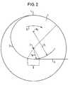
- the embodiment shown in FIG. 2differs from the embodiment of FIG. 1 in that here the radius of curvature r K changes over the outer surface 3 of the winding drum 1.
- the radius of curvatureincreases to a value of 75 mm in the area 5 of the casing surface 3.
- the center of curvature M Kis increasingly moving away from the axis of rotation I of the winding drum 1.
- the radius of curvature r Kcan remain constant, in particular over the section 5. This configuration allows the radius of curvature r K to be in the critical range 5 further enlarged and the bending load on the pull rope 2 can be further reduced.
- FIG. 3shows a comparison of the jacket contours of the two locking devices according to the invention shown in FIGS. 1 and 2 and the jacket contour of a known locking device.
- the line 3 0corresponds to the outer surface of the winding drum 1 of a conventional locking device, the line 3 1 the outer surface of the variant of FIG. 1 and the line 3 2 of the outer surface of the variant of FIG. 2.
- the radius of curvature r K of the two lateral surfaces 3 1 and 3 2 in section 5is significantly larger than the radius of curvature r K of the lateral surface 3 0 in this area.
- the winding radii r Wdiffer only slightly in this area, and thus also the closing speed and closing force.
- the sheath contour according to the inventionthus easily reduces the bending load on the pull cable 2 and thus increases its service life.
Landscapes
- Engineering & Computer Science (AREA)
- Mechanical Engineering (AREA)
- Window Of Vehicle (AREA)
- Power-Operated Mechanisms For Wings (AREA)
- Storage Of Web-Like Or Filamentary Materials (AREA)
- Operating, Guiding And Securing Of Roll- Type Closing Members (AREA)
- Storing, Repeated Paying-Out, And Re-Storing Of Elongated Articles (AREA)
Abstract
Description
Translated fromGermanDie vorliegende Erfindung betrifft eine Schließvorrichtung, insbesondere für automatisch verschließbare Fahrzeugtüren, mit einem an dem Schließobjekt angreifenden Zugmittel und einer motorisch antreibbaren Wickeltrommel, auf welche das Zugmittel aufwickelbar ist und deren Außenkontur im Wickelbereich des Zugmittels in Umfangsrichtung betrachtet derart ausgebildet ist, daß der Wickelradius, also der Abstand der Trommelmantelfläche von der Trommeldrehachse, zumindest in dem in der Endphase der Schließbewegung wirksamen Mantelabschnitt kleiner ist als in dem in der vorhergehenden Schließphase wirksamen Mantelabschnitt.The present invention relates to a locking device, in particular for automatically lockable vehicle doors, with a pulling means acting on the locking object and a motor-driven winding drum, onto which the pulling means can be wound and the outer contour of which, viewed in the circumferential direction in the winding area of the pulling means, is designed such that the winding radius, thus the distance of the drum jacket surface from the drum axis of rotation, at least in the jacket section effective in the final phase of the closing movement, is smaller than in the jacket section effective in the previous closing phase.
Bei automatisch verschließbaren Fahrzeugtüren darf die Schließgeschwindigkeit der Türe aus Sicherheitsgründen in der Endphase des Schließvorganges einen festgelegten Wert nicht überschreiten. Um dennoch ein Schließen der Türe in kurzer Zeit zu ermöglichen, wird die Schließgeschwindigkeit in der Endphase ausgehend von einer vorhergehenden hohen Schließgeschwindigkeit auf die geforderte Geschwindigkeit reduziert. Dies wird bei den Schließvorrichtungen der eingangs genannten Art durch eine Außenkontur der Wickeltrommel erreicht, durch die der Wickelradius in der Endphase der Schließbewegung reduziert ist. Dadurch reduziert sich die Schließgeschwindigkeit bei gleichbleibender Drehgeschwindigkeit der Wickeltrommel in der gewünschten Weise.In the case of automatically lockable vehicle doors, the closing speed of the door may not exceed a specified value in the final phase of the closing process for safety reasons. In order to enable the door to be closed quickly, the closing speed in the final phase is reduced from the previous high closing speed to the required speed. In the case of the closing devices of the type mentioned at the outset, this is achieved by an outer contour of the winding drum, through which the winding radius is reduced in the final phase of the closing movement. This reduces the closing speed in the desired manner while the rotational speed of the winding drum remains the same.
Ein Nachteil der Ausgestaltung der Wickeltrommel mit reduziertem Wickelradius besteht darin, daß sich der Biegeradius des Zugmittels in diesem Bereich entsprechend reduziert. Durch den reduzierten Biegeradius wird die Lebensdauer des Zugmittels beeinträchtigt, zumal in der Endphase des Schließvorganges die Zugbelastung des Zugmittels maximal ist. In der Endphase muß nämlich eine ausreichende Schließkraft für die Türe vorliegen, die sich aus den Türdichtungskräften, den Maßen und dem Gewicht der Türe, der Betätigungskraft des Türschlosses und den mechanisch zu betätigenden elektrischen Türkontakten ergibt. Die Lebensdauer des Zugmittels wird dadurch zum bestimmenden Faktor für die Lebensdauer der Schließvorrichtung insgesamt.A disadvantage of the design of the winding drum with a reduced winding radius is that the bending radius of the traction means is reduced accordingly in this area. The reduced bending radius affects the lifespan of the traction device, especially since the traction load of the traction device is at a maximum in the final phase of the closing process. In the final phase, there must be a sufficient closing force for the door, which results from the door sealing forces, the dimensions and weight of the door, the actuating force of the door lock and the mechanically operated electrical door contacts. The lifespan of the traction device thus becomes the determining factor for the lifespan of the locking device as a whole.
Der Erfindung liegt die Aufgabe zugrunde, die Dauerhaltbarkeit des Zugmittels und damit der Schließvorrichtung zu erhöhen.The invention has for its object to increase the durability of the traction device and thus the locking device.
Diese Aufgabe wird dadurch gelöst, daß der in der Endphase der Schließbewegung wirksame Mantelabschnitt der Wickeltrommel eine Krümmung mit einem Krümmungsradius aufweist, welcher größer ist als der Wickelradius in diesem Bereich.This object is achieved in that the jacket section of the winding drum which is effective in the final phase of the closing movement has a curvature with a radius of curvature which is greater than the winding radius in this area.
Durch die erfindungsgemäße Ausgestaltung der Außenkontur der Wickeltrommel kann die Biegebelastung des Zugmittels in der kritischen Endphase des Schließvorganges deutlich verringert und dessen Lebensdauer entsprechend erhöht werden, da der Biegeradius gegenüber bekannten Schließvorrichtungen vergrößert werden kann.The inventive design of the outer contour of the winding drum can significantly reduce the bending load on the traction means in the critical final phase of the closing process and its service life be increased accordingly, since the bending radius can be increased compared to known locking devices.
Da der in der Schließphase wirksame Mantelabschnitt verhältnismäßig klein ist, insbesondere nur einem Drehwinkel von etwa 60° entspricht, werden Schließgeschwindigkeit und Schließkraft durch die Vergrößerung des Krümmungsradius nur unwesentlich verändert.Since the sheath section effective in the closing phase is relatively small, in particular corresponds only to an angle of rotation of approximately 60 °, the closing speed and closing force are changed only insignificantly by increasing the radius of curvature.
Der Grundgedanke der Erfindung besteht also darin, den Krümmungsradius des für die Endphase des Schließvorganges maßgeblichen Mantelabschnittes größer zu wählen als den Wickelradius, indem der Mittelpunkt der Mantelkrümmung in geeigneter Weise von der Drehachse der Wickeltrommel weg verlegt wird. Im Gegensatz zu den bekannten Schließvorrichtungen fällt bei der erfindungsgemäßen Vorrichtung der Krümmungsmittelpunkt also nicht mit der Drehachse der Wickeltrommel zusammen. Dadurch kann trotz kleinem Wickelradius ein großer Biegeradius des Zugmittels erreicht werden, also eine geringe Schließgeschwindigkeit bei gleichzeitig verringerter Zugbelastung des Zugmittels.The basic idea of the invention is therefore to choose the radius of curvature of the jacket section which is decisive for the end phase of the closing process to be larger than the winding radius, in that the center of the jacket curvature is suitably moved away from the axis of rotation of the winding drum. In contrast to the known closing devices, the center of curvature does not coincide with the axis of rotation of the winding drum in the device according to the invention. In this way, despite the small winding radius, a large bending radius of the traction device can be achieved, that is, a low closing speed with a reduced tensile load on the traction device.
Nach einer Ausgestaltung der Erfindung ist der Krümmungsradius des in der Schließphase wirksamen Mantelabschnitts der Wickeltrommel annähernd mindestens doppelt so groß wie der Wickelradius. Bevorzugt ist der Krümmungsradius in diesem Mantelabschnitt annähernd eineinhalb mal so groß wie der Wickelradius. Durch diese Wahl wird die Lebensdauer des Zugmittels soweit erhöht, daß sie mit den übrigen Bauteilen der Schließvorrichtung in etwa übereinstimmt.According to one embodiment of the invention, the radius of curvature of the jacket section of the winding drum which is effective in the closing phase is approximately at least twice as large as the winding radius. The radius of curvature in this jacket section is preferably approximately one and a half times as large as the winding radius. This choice increases the lifespan of the traction device to such an extent that it approximately corresponds to the other components of the locking device.
Nach einer weiteren Ausgestaltung der Erfindung ist der Krümmungsradius des in der Schließphase wirksamen Mantelabschnitts über diesen Mantelabschnitt konstant. Dies gewährleistet während der gesamten Endphase geringe Biegekräfte bei gleichzeitig einfacher Herstellbarkeit der Trommel, insbesondere wenn nach einer weiteren Ausgestaltung der Erfindung der Krümmungsradius über die gesamte wirksame Mantelfläche konstant ist.According to a further embodiment of the invention, the radius of curvature of the jacket section effective in the closing phase is constant over this jacket section. This ensures low bending forces during the entire final phase while at the same time making the drum easier to manufacture, in particular if, according to a further embodiment of the invention, the radius of curvature is constant over the entire effective surface area.
Nach einer weiteren Ausgestaltung der Erfindung ist der Krümmungsradius der Wickeltrommel in dem in der Schließphase wirksamen Mantelabschnitts größer als außerhalb dieses Mantelabschnitts, insbesondere größer als in der Anfangsposition. Gerade in der kritischen Endphase mit der maximalen Zugbelastung kann die Biegebelastung dadurch besonders klein gehalten werden.According to a further embodiment of the invention, the radius of curvature of the winding drum is greater in the jacket section effective in the closing phase than outside this jacket section, in particular larger than in the initial position. Especially in the critical final phase with the maximum tensile load, the bending load can be kept particularly low.
Als Zugmittel kann insbesondere ein Zugseil dienen, welches vorteilhafterweise in einer Nut der Wickeltrommel geführt ist.In particular, a traction cable can be used as the traction means, which is advantageously guided in a groove of the winding drum.
Zwei Ausführungsbeispiele der Erfindung sind in der Zeichnung dargestellt und werden nachfolgend beschrieben. Es zeigen, jeweils in schematischer Darstellung,
- Fig. 1
- die Wickeltrommelkontur einer ersten Variante der Erfindung,
- Fig. 2
- die Wickeltrommelkontur einer zweiten Variante der Erfindung und
- Fig. 3
- eine Gegenüberstellung der Wickeltrommelkonturen der Varianten von Fig. 1 und Fig. 2 mit der Wickeltrommelkontur einer bekannten Schließvorrichtung.
- Fig. 1
- the winding drum contour of a first variant of the invention,
- Fig. 2
- the winding drum contour of a second variant of the invention and
- Fig. 3
- a comparison of the winding drum contours of the variants of FIGS. 1 and 2 with the winding drum contour of a known locking device.
Fig. 1 zeigt eine Trommel 1 im Querschnitt. Die Trommel 1 ist um eine Achse I drehbar gelagert und motorisch antreibbar. Dabei ist auf die Trommel 1 ein Zugseil 2 auf- und abwickelbar. Die Aufwickelrichtung ist mit Pfeil II gekennzeichnet. Die Mantelfläche 3 der Trommel 1 im Aufwickelbereich des Zugseils 2, bei dem es sich insbesondere um eine Nut handelt, weist eine Kontur auf, die so ausgebildet ist, daß sich der Wickelradius rW, also der Abstand zwischen Mantelfläche 3 und Drehachse I, ausgehend von einem maximalen Anfangswert an einer Mantelposition 4 auf einen gewünschten Wert in demjenigen Mantelabschnitt 5 verringert, auf welchen das Zugseil 2 in der Endphase der Schließbewegung aufgewickelt wird. Die Kontur der Mantelfläche 3 ist dabei aber so gewählt daß der Krümmungsradius rK in dem insbesondere einen Drehwinkel von 60° umfassenden Mantelabschnitt 5 größer ist als der Wickelradius rW in diesem Bereich. Der Krümmungsmittelpunkt MK liegt also nicht auf der Drehachse I der Wickeltrommel 1, sondern von der Mantelfläche 3 weiter entfernt.Fig. 1 shows a
In dem dargestellten Beispiel in Fig. 1 beträgt der Krümmungsradius rK im Mantelabschnitt 5 konstant 60 mm. Wie dargestellt, kann dieser Wert bereits vor dem Mantelabschnitt 5 und insbesondere über die gesamte wirksame Mantelfläche 3 vorliegen. Dementsprechend nimmt der Wickelradius rW im Mantelabschnitt 5 von einem in der Mitte des Abschnitts 5 erreichten Minimalwert, im dargestellten Beispiel 30 mm, wieder zu. Die dadurch bedingte Vergrößerung des Wickelradius rW gegenüber dem Wickelradius bei bekannten Schließvorrichtungen ist so gering, daß dies auf die Schließkraft und Schließgeschwindigkeit keine nachteilige Auswirkung hat.In the example shown in FIG. 1, the radius of curvature rK in the
Bei dem Ausführungsbeispiel von Fig. 1 beträgt der Krümmungsradius in der Mantelfläche 3 also durchgängig 60 mm. Entsprechend groß ist der Biegeradius des aufgewickelten Zugseils 2, dessen Biegebelastung insbesondere im Mantelbereich 5 entsprechend geringer ist als bei herkömmlichen Schließvorrichtungen dieser Art.In the embodiment of FIG. 1, the radius of curvature in the
Das in Fig. 2 dargestellte Ausführungsbeispiel unterscheidet sich von dem Ausführungsbeispiel von Fig. 1 dadurch, daß sich hier der Krümmungsradius rK über die Mantelfläche 3 der Wickeltrommel 1 verändert. Ausgehend von einem mit dem Wert des Ausführungsbeispiels von Fig. 1 übereinstimmenden Wert an der Mantelposition 4 nimmt der Krümmungsradius auf einen Wert von 75 mm im Bereich 5 der Mantelfläche 3 zu. Das heißt, der Krümmungsmittelpunkt MK entfernt sich zunehmend von der Drehachse I der Wickeltrommel 1. Ab einer gewissen Stelle der Mantelfläche 3 kann der Krümmungsradius rK konstant bleiben, insbesondere über den Abschnitt 5. Durch diese Ausgestaltung kann der Krümmungsradius rK im kritischen Bereich 5 weiter vergrößert und die Biegebelastung des Zugseils 2 weiter verringert werden.The embodiment shown in FIG. 2 differs from the embodiment of FIG. 1 in that here the radius of curvature rK changes over the
Fig. 3 zeigt eine Gegenüberstellung der Mantelkonturen der beiden in den Fig. 1 und 2 dargestellten erfindungsgemäßen Schließvorrichtungen und der Mantelkontur einer bekannten Schließvorrichtung. Die Linie 30 entspricht dabei der Mantelfläche der Wickeltrommel 1 einer konventionellen Schließvorrichtung, die Linie 31 der Mantelfläche der Variante von Fig. 1 und die Linie 32 der Mantelfläche der Variante von Fig. 2. Wie man sieht, ist der Krümmungsradius rK der beiden Mantelflächen 31 und 32 im Abschnitt 5 deutlich größer als der Krümmungsradius rK der Mantelfläche 30 in diesem Bereich. Die Wickelradien rW unterscheiden sich in diesem Bereich dagegen nur wenig, und damit auch Schließgeschwindigkeit und Schließkraft. Durch die erfindungsgemäße Mantelkontur wird somit in einfacher Weise eine Verringerung der Biegebelastung des Zugseils 2 und damit eine Erhöhung von dessen Lebensdauer erreicht.FIG. 3 shows a comparison of the jacket contours of the two locking devices according to the invention shown in FIGS. 1 and 2 and the jacket contour of a known locking device. The
- 11
- WickeltrommelWinding drum
- 22nd
- ZugseilTraction rope
- 33rd
- MantelflächeLateral surface
- 44th
- AnfangspositionStarting position
- 55
- Abschnitt von 3Section of 3
- II.
- Drehachse von 1Axis of rotation of 1
- IIII
- DrehrichtungspfeilDirection of rotation arrow
- rKrK
- KrümmungsradiusRadius of curvature
- rWrW
- WickelradiusWinding radius
- MKMK
- KrümmungsmittelpunktCenter of curvature
Claims (8)
Translated fromGermandadurchgekennzeichnet,
daß der in der Endphase der Schließbewegung wirksame Mantelabschnitt (5) der Wickeltrommel (1) eine Krümmung mit einem Krümmungsradius (rK) aufweist, welcher größer ist als der Wickelradius (rW) in diesem Bereich.Locking device, in particular for automatically lockable vehicle doors, with a pulling means (2) acting on the locking object and a motorized winding drum (1), onto which the pulling means (2) can be wound and whose outer contour (3) in the winding area of the pulling means (2) in Considered circumferential direction is designed such that the winding radius (rW ), i.e. the distance of the drum jacket surface (3) from the drum axis of rotation (I), is smaller than in the previous one, at least in the jacket section (5) which is effective in the final phase of the closing movement Effective phase of the jacket section,
characterized by
that the jacket section (5) of the winding drum (1) effective in the final phase of the closing movement has a curvature with a radius of curvature (rK ) which is greater than the winding radius (rW ) in this area.
dadurchgekennzeichnet,
daß der Krümmungsradius (rK) des in der Schließphase wirksamen Mantelabschnitts (5) annähernd mindestens doppelt so groß ist wie der Wickelradius (rW) in diesem Bereich.Locking device according to claim 1,
characterized by
that the radius of curvature (rK ) of the jacket section (5) active in the closing phase is approximately at least twice as large as the winding radius (rW ) in this area.
dadurchgekennzeichnet,
daß der Krümmungsradius (rK) des in der Schließphase wirksamen Mantelabschnitts (5) etwa eineinhalb mal so groß ist wie der Wickelradius (rW).Locking device according to claim 2,
characterized by
that the radius of curvature (rK ) of the jacket section (5) effective in the closing phase is about one and a half times as large as the winding radius (rW ).
dadurchgekennzeichnet,
daß der Krümmungsradius (rK) in dem in der Schließphase wirksamen Mantelabschnitt (5) konstant ist.Locking device according to one of the preceding claims,
characterized by
that the radius of curvature (rK ) is constant in the jacket section (5) effective in the closing phase.
dadurchgekennzeichnet,
daß der Krümmungsradius (rK) über die gesamte wirksame Mantelfläche (3) konstant ist.Locking device according to claim 4,
characterized by
that the radius of curvature (rK ) is constant over the entire effective lateral surface (3).
dadurchgekennzeichnet,
daß der Krümmungsradius (rK) der Wickeltrommel (1) in dem in der Schließphase wirksamen Mantelabschnitt (5) größer ist als außerhalb dieses Mantelabschnitts (5), insbesondere größer als in der Anfangsposition (4).Locking device according to one of claims 1 to 4,
characterized by
that the radius of curvature (rK ) of the winding drum (1) in the sheath section (5) effective in the closing phase is larger than outside this sheath section (5), in particular larger than in the initial position (4).
dadurchgekennzeichnet,
daß als Zugmittel ein Zugseil (2) dient.Locking device according to one of the preceding claims,
characterized by
that a traction rope (2) serves as the traction means.
dadurchgekennzeichnet,
daß das Zugseil (2) in einer Nut der Wickeltrommel (1) geführt ist.Locking device according to claim 7,
characterized by
that the pull rope (2) is guided in a groove of the winding drum (1).
Applications Claiming Priority (2)
| Application Number | Priority Date | Filing Date | Title |
|---|---|---|---|
| DE19818295 | 1998-04-23 | ||
| DE19818295ADE19818295A1 (en) | 1998-04-23 | 1998-04-23 | Locking device, in particular for automatically lockable vehicle doors |
Publications (2)
| Publication Number | Publication Date |
|---|---|
| EP0952292A1true EP0952292A1 (en) | 1999-10-27 |
| EP0952292B1 EP0952292B1 (en) | 2005-11-30 |
Family
ID=7865644
Family Applications (1)
| Application Number | Title | Priority Date | Filing Date |
|---|---|---|---|
| EP99107913AExpired - LifetimeEP0952292B1 (en) | 1998-04-23 | 1999-04-21 | Closing device, especially for automatically closing vehicle doors |
Country Status (4)
| Country | Link |
|---|---|
| EP (1) | EP0952292B1 (en) |
| JP (1) | JP3535036B2 (en) |
| KR (1) | KR100328958B1 (en) |
| DE (2) | DE19818295A1 (en) |
Families Citing this family (5)
| Publication number | Priority date | Publication date | Assignee | Title |
|---|---|---|---|---|
| US8225458B1 (en) | 2001-07-13 | 2012-07-24 | Hoffberg Steven M | Intelligent door restraint |
| JP4262198B2 (en) | 2004-12-28 | 2009-05-13 | 三井金属鉱業株式会社 | Door opener |
| JP4979227B2 (en)* | 2005-11-24 | 2012-07-18 | 株式会社ハイレックスコーポレーション | Cable winding drum and back door assist device using the drum |
| KR101583533B1 (en)* | 2013-12-24 | 2016-01-08 | 주식회사 서궁 | work loading device |
| DE202015103418U1 (en)* | 2015-06-29 | 2016-10-04 | Dura Automotive Systems Gmbh | Device for changing the position of moving bodies and vehicle with such a device |
Citations (1)
| Publication number | Priority date | Publication date | Assignee | Title |
|---|---|---|---|---|
| US5323570A (en)* | 1993-01-25 | 1994-06-28 | General Motors Corporation | Door opening cable system with cable slack take-up |
Family Cites Families (2)
| Publication number | Priority date | Publication date | Assignee | Title |
|---|---|---|---|---|
| CA2031616C (en)* | 1990-04-25 | 1994-12-13 | David Edward Compeau | Power sliding door closure |
| US5316365A (en)* | 1993-01-25 | 1994-05-31 | General Motors Corporation | Sliding door closed loop cable closure system with balanced cable tension and varying diameter pulleys |
- 1998
- 1998-04-23DEDE19818295Apatent/DE19818295A1/ennot_activeCeased
- 1999
- 1999-04-19KRKR1019990013762Apatent/KR100328958B1/ennot_activeExpired - Fee Related
- 1999-04-21DEDE59912848Tpatent/DE59912848D1/ennot_activeExpired - Lifetime
- 1999-04-21EPEP99107913Apatent/EP0952292B1/ennot_activeExpired - Lifetime
- 1999-04-22JPJP11465599Apatent/JP3535036B2/ennot_activeExpired - Fee Related
Patent Citations (1)
| Publication number | Priority date | Publication date | Assignee | Title |
|---|---|---|---|---|
| US5323570A (en)* | 1993-01-25 | 1994-06-28 | General Motors Corporation | Door opening cable system with cable slack take-up |
Also Published As
| Publication number | Publication date |
|---|---|
| JP3535036B2 (en) | 2004-06-07 |
| DE19818295A1 (en) | 1999-10-28 |
| KR100328958B1 (en) | 2002-03-20 |
| EP0952292B1 (en) | 2005-11-30 |
| DE59912848D1 (en) | 2006-01-05 |
| KR19990083301A (en) | 1999-11-25 |
| JPH11336416A (en) | 1999-12-07 |
Similar Documents
| Publication | Publication Date | Title |
|---|---|---|
| DE10356306B4 (en) | Motor vehicle lock | |
| EP0175996B1 (en) | Drive unit particularly for moving window screens, gliding roofs, seats and similar vehicle devices | |
| EP0503315A2 (en) | Winding device for winding and unwinding a cable | |
| EP0082375A2 (en) | Geared motor, in particular an electromotive window-lifting drive | |
| EP0952292A1 (en) | Closing device, especially for automatically closing vehicle doors | |
| WO2023036364A1 (en) | Motor vehicle lock, in particular motor vehicle door lock | |
| DE19549747B4 (en) | Transport system for a wound electrical conductor with winding inversion by looping | |
| EP0793028B1 (en) | Length-adjusting device for bowden cable actuated window lifters | |
| EP0809580B1 (en) | Device for transmitting electrical signals between components which can be rotated relative to one another | |
| WO2006002651A1 (en) | Transmission device for transmitting electric signals between a rotor and a stator | |
| EP0257604B1 (en) | Guide element with a clamp | |
| DE3448351C2 (en) | Drive device for a window regulator | |
| DE60107161T2 (en) | Support plate for a motor vehicle door with integrated socket for a window lift drive | |
| EP0716203B1 (en) | Cable drive, especially for a garage door | |
| EP4019812A1 (en) | Parking lock and transmission with a parking lock | |
| EP1109271B1 (en) | Series of devices for signal transmission between two end stations | |
| EP3163007B1 (en) | Device for a drive cutoff of a motorized drive of a roller shutter shaft | |
| EP1993190A2 (en) | Shaft thrust bearing, electric drive and power window | |
| DE60205200T2 (en) | Compact cable window lifter | |
| DE102020201696A1 (en) | Cable drive device of a motor vehicle | |
| EP0670246B1 (en) | Signal transmission installation between two terminals | |
| EP0349005B1 (en) | Hinge | |
| EP3919327B1 (en) | Camera assembly | |
| DE4112182C1 (en) | ||
| DE2651607A1 (en) | Motor vehicle window lifting mechanism - has crank pin and gear wheel with projections for operation |
Legal Events
| Date | Code | Title | Description |
|---|---|---|---|
| PUAI | Public reference made under article 153(3) epc to a published international application that has entered the european phase | Free format text:ORIGINAL CODE: 0009012 | |
| AK | Designated contracting states | Kind code of ref document:A1 Designated state(s):DE FR GB IT | |
| AX | Request for extension of the european patent | Free format text:AL;LT;LV;MK;RO;SI | |
| 17P | Request for examination filed | Effective date:19991123 | |
| AKX | Designation fees paid | Free format text:DE FR GB IT | |
| 17Q | First examination report despatched | Effective date:20011219 | |
| GRAP | Despatch of communication of intention to grant a patent | Free format text:ORIGINAL CODE: EPIDOSNIGR1 | |
| GRAS | Grant fee paid | Free format text:ORIGINAL CODE: EPIDOSNIGR3 | |
| GRAA | (expected) grant | Free format text:ORIGINAL CODE: 0009210 | |
| AK | Designated contracting states | Kind code of ref document:B1 Designated state(s):DE FR GB IT | |
| PG25 | Lapsed in a contracting state [announced via postgrant information from national office to epo] | Ref country code:GB Free format text:LAPSE BECAUSE OF FAILURE TO SUBMIT A TRANSLATION OF THE DESCRIPTION OR TO PAY THE FEE WITHIN THE PRESCRIBED TIME-LIMIT Effective date:20051130 | |
| REG | Reference to a national code | Ref country code:GB Ref legal event code:FG4D Free format text:NOT ENGLISH | |
| REF | Corresponds to: | Ref document number:59912848 Country of ref document:DE Date of ref document:20060105 Kind code of ref document:P | |
| GBV | Gb: ep patent (uk) treated as always having been void in accordance with gb section 77(7)/1977 [no translation filed] | Effective date:20051130 | |
| ET | Fr: translation filed | ||
| PLBE | No opposition filed within time limit | Free format text:ORIGINAL CODE: 0009261 | |
| STAA | Information on the status of an ep patent application or granted ep patent | Free format text:STATUS: NO OPPOSITION FILED WITHIN TIME LIMIT | |
| 26N | No opposition filed | Effective date:20060831 | |
| PGFP | Annual fee paid to national office [announced via postgrant information from national office to epo] | Ref country code:FR Payment date:20080312 Year of fee payment:10 | |
| PGFP | Annual fee paid to national office [announced via postgrant information from national office to epo] | Ref country code:IT Payment date:20080429 Year of fee payment:10 | |
| REG | Reference to a national code | Ref country code:FR Ref legal event code:ST Effective date:20091231 | |
| PG25 | Lapsed in a contracting state [announced via postgrant information from national office to epo] | Ref country code:FR Free format text:LAPSE BECAUSE OF NON-PAYMENT OF DUE FEES Effective date:20091222 | |
| PG25 | Lapsed in a contracting state [announced via postgrant information from national office to epo] | Ref country code:IT Free format text:LAPSE BECAUSE OF NON-PAYMENT OF DUE FEES Effective date:20090421 | |
| PGFP | Annual fee paid to national office [announced via postgrant information from national office to epo] | Ref country code:DE Payment date:20180628 Year of fee payment:20 | |
| REG | Reference to a national code | Ref country code:DE Ref legal event code:R071 Ref document number:59912848 Country of ref document:DE |