EP0951862B1 - Medical observing instrument - Google Patents
Medical observing instrumentDownload PDFInfo
- Publication number
- EP0951862B1 EP0951862B1EP99202257AEP99202257AEP0951862B1EP 0951862 B1EP0951862 B1EP 0951862B1EP 99202257 AEP99202257 AEP 99202257AEP 99202257 AEP99202257 AEP 99202257AEP 0951862 B1EP0951862 B1EP 0951862B1
- Authority
- EP
- European Patent Office
- Prior art keywords
- image
- optical system
- microscope
- endoscope
- lens
- Prior art date
- Legal status (The legal status is an assumption and is not a legal conclusion. Google has not performed a legal analysis and makes no representation as to the accuracy of the status listed.)
- Expired - Lifetime
Links
- 230000003287optical effectEffects0.000claimsdescription40
- 239000013307optical fiberSubstances0.000description7
- 210000004556brainAnatomy0.000description4
- 230000036772blood pressureEffects0.000description2
- 238000010276constructionMethods0.000description2
- 238000005286illuminationMethods0.000description2
- 230000005540biological transmissionEffects0.000description1
- 238000007796conventional methodMethods0.000description1
- 230000000414obstructive effectEffects0.000description1
Images


Classifications
- G—PHYSICS
- G02—OPTICS
- G02B—OPTICAL ELEMENTS, SYSTEMS OR APPARATUS
- G02B23/00—Telescopes, e.g. binoculars; Periscopes; Instruments for viewing the inside of hollow bodies; Viewfinders; Optical aiming or sighting devices
- G02B23/24—Instruments or systems for viewing the inside of hollow bodies, e.g. fibrescopes
- G02B23/2407—Optical details
- G02B23/2453—Optical details of the proximal end
- A—HUMAN NECESSITIES
- A61—MEDICAL OR VETERINARY SCIENCE; HYGIENE
- A61B—DIAGNOSIS; SURGERY; IDENTIFICATION
- A61B1/00—Instruments for performing medical examinations of the interior of cavities or tubes of the body by visual or photographical inspection, e.g. endoscopes; Illuminating arrangements therefor
- A61B1/00163—Optical arrangements
- A61B1/00193—Optical arrangements adapted for stereoscopic vision
- A—HUMAN NECESSITIES
- A61—MEDICAL OR VETERINARY SCIENCE; HYGIENE
- A61B—DIAGNOSIS; SURGERY; IDENTIFICATION
- A61B1/00—Instruments for performing medical examinations of the interior of cavities or tubes of the body by visual or photographical inspection, e.g. endoscopes; Illuminating arrangements therefor
- A61B1/04—Instruments for performing medical examinations of the interior of cavities or tubes of the body by visual or photographical inspection, e.g. endoscopes; Illuminating arrangements therefor combined with photographic or television appliances
- A61B1/042—Instruments for performing medical examinations of the interior of cavities or tubes of the body by visual or photographical inspection, e.g. endoscopes; Illuminating arrangements therefor combined with photographic or television appliances characterised by a proximal camera, e.g. a CCD camera
- A—HUMAN NECESSITIES
- A61—MEDICAL OR VETERINARY SCIENCE; HYGIENE
- A61B—DIAGNOSIS; SURGERY; IDENTIFICATION
- A61B3/00—Apparatus for testing the eyes; Instruments for examining the eyes
- A61B3/10—Objective types, i.e. instruments for examining the eyes independent of the patients' perceptions or reactions
- A61B3/13—Ophthalmic microscopes
- A61B3/132—Ophthalmic microscopes in binocular arrangement
- G—PHYSICS
- G02—OPTICS
- G02B—OPTICAL ELEMENTS, SYSTEMS OR APPARATUS
- G02B21/00—Microscopes
- G02B21/0004—Microscopes specially adapted for specific applications
- G02B21/0012—Surgical microscopes
- G—PHYSICS
- G02—OPTICS
- G02B—OPTICAL ELEMENTS, SYSTEMS OR APPARATUS
- G02B21/00—Microscopes
- G02B21/18—Arrangements with more than one light path, e.g. for comparing two specimens
- G02B21/20—Binocular arrangements
- G—PHYSICS
- G02—OPTICS
- G02B—OPTICAL ELEMENTS, SYSTEMS OR APPARATUS
- G02B23/00—Telescopes, e.g. binoculars; Periscopes; Instruments for viewing the inside of hollow bodies; Viewfinders; Optical aiming or sighting devices
- G02B23/24—Instruments or systems for viewing the inside of hollow bodies, e.g. fibrescopes
- G02B23/2476—Non-optical details, e.g. housings, mountings, supports
- G02B23/2484—Arrangements in relation to a camera or imaging device
Definitions
- This inventionrelates to a medical observing instrument for the use in a micro-operation with respect to the ear, eye, brain, etc. of a patient.
- a microscopeis used in a micro-operation with respect to the ear, eye, brain, etc. of a patient.
- the operatorperforms an operation while observing an enlarged image of a diseased part of the patient and with the eyes placed coincident with a pair of ocular lens of a microscope.
- the microscopeis usually supported in its suspending or hanging-down state. Therefore, the operator can see the diseased part only from a limited range of angles. However, it sometimes occurs that the operator is required to observe the diseased part from different angles during operation.
- the operator or an assistant to the operatormanually holds an endoscope with an image sensor and brings it toward the diseased part.
- An image obtained by the endoscopeis displayed in a monitor television which is located in place away from the microscope.
- JP-A-5215970discloses a medical observing instrument comprising a microscope having a body and an enlarging optical system received in the body, the enlarging optical system including an objective lens and an ocular lens; an endoscope separated from the microscope; and image display means connected to the endoscope for displaying an image obtained by the endoscope.
- a medical observing instrumentcomprising a microscope having a body and an enlarging optical system received in the body, the enlarging optical system including an objective lens and an ocular lens; an endoscope separated from the microscope; and image display means connected to the endoscope for displaying an image obtained by the endoscope.
- the present inventionprovides an improvement over these known devices, and provides a medical observing instrument having the features set out in claim 1.
- a medical observing instrumentcomprises, as principal component elements, a microscope 10 and an endoscope 20.
- the microscope 10has a binocular-like body 11.
- This body 11has a base portion 11x, and a pair of ocular portions 11a, 11b projecting from a rear surface of the base portion 11x.
- the body 11is supported by a hanging device, not shown, such that the position of body 11 can be adjusted.
- a pair of enlarging optical systems 10a, 10bare received in the body 11.
- Each of the enlarging optical systems 10a, 10bincludes, as in the case with the conventional microscope, an objective lens 12, prisms 13, 14, and ocular lens 15.
- the microscope 10includes an optical system (not shown) for emitting an illumination light to a diseased part of a patient.
- beam splitters 16a, 16bare disposed respectively on optical paths A , B of the enlarging optical systems 10a, 10b between the prism 14 and the ocular lens 15.
- the ocular lens 15 and the beam splitter 16a of the enlarging optical system 10aare received in the ocular portion 11a.
- the ocular lens 15 and the beam splitter 16b of the enlarging optical system 10bare received in the other ocular portion 11b of the body 11.
- the body 11has auxiliary receiving portions 11a', 11b' projecting at right angles respectively from the ocular portions 11a, 11b.
- a micro-monitor television 30image display means
- a lens 31 and a shutter 32are arranged in this order toward the beam splitter 16a.
- An optical path X where the monitor television 30, the lens 31 and the shutter 32 are arrangedis intersected with the optical path A of the enlarging optical system 10a at the beam splitter 16a. The angle of intersection is somewhat smaller or larger than 90 degrees.
- a screen of the monitor television 30is intersected at right angles with the optical path X.
- this endoscope 20has a body 21 and a hard tube 22 extending from the body 21.
- the tube 22has an illuminating window and an observing window (both not shown) formed in a distal end of the tube 22.
- An illumination lightis supplied from the illuminating window through a bundle of optical fibers extending through the body 21 and the tube 22.
- An image sensor 23such as a CCD or the like is faced with the observing window through a lens.
- This image sensor 23is connected to a control unit 25 (control means) through signal wires 24.
- This control unit 25is operated to control the image sensor 23, prepares a television signal based on a picture signal from the image sensor 23 and sends it to the monitor television 30.
- Various means for detecting the conditions of the patientsuch as a sphygmomanometer 28a, a heartbeat meter 28b, an electroencephaloscope 28c and the like are connected to the control unit 25.
- the control unit 25prepares a picture signal indicative of a numeric figure based on blood pressure data obtainable from the sphygmomanometer 28a, prepares a picture signal representative of a numeric figure and a waveform based on heartbeat data obtainable from the heartbeat meter 28b, prepares a picture signal indicative of a waveform based on brain wave data obtainable from the electroencephaloscope 28c, combines them with the picture signal from the image sensor, and sends them to the monitor television 30.
- the numerical figures and waveformsare displayed in a certain area, for example, a right and down corner area of the screen of the monitor television 30.
- the circuit portion of the control unit 25may be built in the monitor television 30.
- an image sensor 40such as a CCD or the like and a lens 41 are arranged in this order toward the beam splitter 16b.
- An optical axis Y where the image sensor 40 and the lens 41 are arrangedis intersected at 90 degrees with the optical path B of the enlarging optical system 10b at the beam splitter 16b.
- An enlarged image obtained by the enlarging optical system 10bis received by the image sensor 40 and can be observed in a large-sized monitor television 45 by an observer other than the operator.
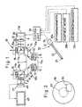
- the operatorplaces the pair of eyes coincident with the pair of ocular lens 15 of the microscope 10. In that state, the operator carries out an operation while observing the enlarged image of the diseased part by the enlarging optical systems 10a, 10b. As shown in Fig. 2, a view field range S1 of this enlarged image occupies a central portion of an entire view field range SO of the ocular lens 15.
- the operatorWhen the operator wants to see the image of the diseased part from a different angle, the operator manually holds the endoscope 20 and causes a distal end of the endoscope 20 to face toward the diseased part. As a consequence, the enlarged image of the diseased part obtained by the image sensor 23 of the endoscope 20 is sent to the monitor television 30 through the control unit 25.
- a push button(not shown) disposed on the body 21 of the endoscope 20 is pushed
- a control circuitnot shown, opens the shutter 32 in response to the actuation of the push button.
- the image displayed in the monitor television 30is reflected by the beam splitter 13 via the lens 31 and the shutter 32 toward one of the eyes of the operator via the ocular lens 15. Consequently, the operator can observe the enlarged image of the diseased part, which is viewed from different angles, displayed in the monitor television 30 without removing the eyes from the pair of ocular lens 15.
- the picture or image of the diseased part in the monitor television 30 observed through one of the pair of ocular lens 15may be about the same in magnifying power as the images obtained by the enlarging optical systems 10a, 10b, or it may be higher or lower.
- a view field scope S2 of the picture or image in the monitor television 30is displaced from the view field range S1 of the enlarged image of the enlarging optical system 10a, the two images are not overlapped at all or they are not overlapped at their important portions. Accordingly, they can be observed simultaneously.
- the picture or image displayed in the monitor television 30is found to be obstructive, the picture or image can be removed from the view field range SO of'the ocular lens 15 by shutting the shutter 32.
- the view field range S2 of the picture or image in the monitor television 30may be overlapped with the view field range S1 of the enlarged image of the enlarging optical system 10a.
- another shutteris interposed between the prism 14 and the beam splitter 16a of the enlarging optical system 10a, and this shutter is shut when the picture or image in the monitor television 30 is observed.
- a monitor television 30is received in an ocular portion 11a of a body 11 of a microscope 10.
- the monitor television 30is placed adjacent to an optical path A (more specifically, adjacent to a prism 14) of the enlarging optical system 10a and faced with an ocular lens 15.
- an enlarged image obtained by the enlarging optical system 10a and a picture or image displayed in the monitor television 30are mutually offset in the view field of the ocular lens 15.
- a microscope 10has only a single enlarging optical system 10a.
- An ocular lens 15 of this enlarging optical system 10ais received in an ocular portion (one of a pair of ocular portions) 11a of a body 11, and another ocular lens 15' is received in the other ocular portion 11b.
- a monitor television 30is also received in the ocular portion 11b in such a manner as to face with the ocular lens 15'.
- the operatorcan observe, by one eye, an enlarged image of the diseased part obtained by the enlarging optical system 10a through the ocular lens 15 and can also observe, by the other eye, a picture or image displayed in the television monitor 30, i.e., an enlarged image of the diseased part obtained by an endoscope.
- a monitor television 30is disposed on an outer surface of a base 11x of a body 11 of a microscope which outer surface is faced with the operator.
- the monitor television 30is disposed between a pair of ocular portions 11a and 11b. The operator can observe an image displayed in the monitor television 30, i.e., an enlarged image of the diseased part obtained by an endoscope.
- an image transmission optical system of an endoscope 20Aincludes an optical fibers bundle 29.
- One end of this optical fibers bundle 29is faced with an observing window through a lens.
- the optical fibers bundle 29is allowed to extend from a body 21.
- the other end portion of the optical fibers bundle 29is received in an auxiliary receiving portion 11a of the body 21 of a microscope 10.
- the other end face 29a of the optical fibers bundle 29is provided as image display means.
- This end face 29ais intersected at right angles with an optical path X and is faced with a beam splitter 16a through a lens 31 and a shutter 32.
- the operatorcan observe not only an enlarged image of the diseased part obtained by an enlarging optical system 10a but also an image obtained by the endoscope 20A through an ocular lens 15.
- the monitor television in the instruments of Figs. 3, 4 and 5may be replaced by the end face of the optical fibers bundle.
Landscapes
- Physics & Mathematics (AREA)
- Health & Medical Sciences (AREA)
- Life Sciences & Earth Sciences (AREA)
- Surgery (AREA)
- Optics & Photonics (AREA)
- General Health & Medical Sciences (AREA)
- General Physics & Mathematics (AREA)
- Engineering & Computer Science (AREA)
- Biomedical Technology (AREA)
- Animal Behavior & Ethology (AREA)
- Veterinary Medicine (AREA)
- Public Health (AREA)
- Biophysics (AREA)
- Heart & Thoracic Surgery (AREA)
- Medical Informatics (AREA)
- Molecular Biology (AREA)
- Astronomy & Astrophysics (AREA)
- Radiology & Medical Imaging (AREA)
- Nuclear Medicine, Radiotherapy & Molecular Imaging (AREA)
- Pathology (AREA)
- Chemical & Material Sciences (AREA)
- Analytical Chemistry (AREA)
- Multimedia (AREA)
- Ophthalmology & Optometry (AREA)
- Endoscopes (AREA)
- Microscoopes, Condenser (AREA)
Description
- This invention relates to a medical observing instrumentfor the use in a micro-operation with respect to the ear, eye,brain, etc. of a patient.
- Lately, as disclosed in "MEDICAL OPTICAL INSTRUMENT" issuedApril 1, 1971 by Nagai Shoten K.K., a microscope is used in amicro-operation with respect to the ear, eye, brain, etc. of apatient. The operator performs an operation while observing anenlarged image of a diseased part of the patient and with theeyes placed coincident with a pair of ocular lens of amicroscope. The microscope is usually supported in itssuspending or hanging-down state. Therefore, the operator cansee the diseased part only from a limited range of angles.However, it sometimes occurs that the operator is required toobserve the diseased part from different angles duringoperation. For this purpose, the operator or an assistant tothe operator manually holds an endoscope with an image sensorand brings it toward the diseased part. An image obtained bythe endoscope is displayed in a monitor television which islocated in place away from the microscope.
- In this conventional method, however, it is necessary forthe operator to temporarily remove the eyes from ocularportions of the microscope in order to observe the monitor television. Since this requires the operator to greatly change the sight line, a smoothoperation is interrupted.
- It is an object of the present invention to provide a medical observing instrument inwhich an operator can observe a diseased part with the aid of an endoscope, without greatlychanging the sight line from that in which the operator observes the diseased part through amicroscope.
- Specification JP-A-5215970 discloses a medical observing instrument comprising amicroscope having a body and an enlarging optical system received in the body, theenlarging optical system including an objective lens and an ocular lens; an endoscopeseparated from the microscope; and image display means connected to the endoscope fordisplaying an image obtained by the endoscope. This enables the diseased part to beviewed by both an operator and, for example, an assistant. In the assembly described inEP-A-0 418 109 a binocular with a beam splitter enables the operator to view the diseasedpart from two angles, i.e. directly and via an endoscope.
- The present invention provides an improvement over these known devices, andprovides a medical observing instrument having the features set out in claim 1.
- Fig.1 is a schematic view showing a medical observinginstrument;
- Fig. 2 is an illustration of a view field of a microscope and a view field of a monitortelevision in one of a pair of ocular portions of the microscope of the medical observinginstrument;
- Fig. 3 is a schematic view showing an important portion ofan embodiment of the invention;
- Fig. 4 is a schematic view showing an important portion ofanother medical observing instrument;
- Fig. 5 is a schematic view showing an important portion ofa still further instrument; and
- Fig. 6 is a schematic view showing a yet furtherinstrument.
- One embodiment not illustrating the present invention will now bedescribed with reference to Figs. 1 and 2. As shown in Fig. 1,a medical observing instrument comprises, as principalcomponent elements, a
microscope 10 and anendoscope 20. - The
microscope 10 has a binocular-like body 11. Thisbody 11 has abase portion 11x, and a pair ofocular portions base portion 11x. Thebody 11 is supported by a hanging device, not shown, such thatthe position ofbody 11 can be adjusted. A pair of enlargingoptical systems body 11. Each ofthe enlargingoptical systems objective lens 12,prisms ocular lens 15. Themicroscope 10 includes an optical system (not shown) for emitting an illumination lightto a diseased part of a patient. - In this embodiment,
beam splitters opticalsystems prism 14 and theocular lens 15.Theocular lens 15 and thebeam splitter 16a of the enlargingoptical system 10a are received in theocular portion 11a. Onthe other hand, theocular lens 15 and thebeam splitter 16b ofthe enlargingoptical system 10b are received in the otherocular portion 11b of thebody 11. - The
body 11 has auxiliary receivingportions 11a', 11b'projecting at right angles respectively from theocularportions auxiliary receiving portion 11a', amicro-monitor television 30 (image display means), alens 31and ashutter 32 are arranged in this order toward thebeamsplitter 16a. An optical path X where themonitor television 30, thelens 31 and theshutter 32 are arranged is intersectedwith the optical pathA of the enlargingoptical system 10a atthebeam splitter 16a. The angle of intersection is somewhatsmaller or larger than 90 degrees. A screen of themonitortelevision 30 is intersected at right angles with the opticalpath X. - An image obtained through the
endoscope 20 is displayed inthemonitor television 30. More specifically, thisendoscope 20 has abody 21 and ahard tube 22 extending from thebody 21. Thetube 22 has an illuminating window and an observing window(both not shown) formed in a distal end of thetube 22. Anillumination light is supplied from the illuminating windowthrough a bundle of optical fibers extending through thebody 21 and thetube 22. Animage sensor 23 such as a CCD or the likeis faced with the observing window through a lens. Thisimagesensor 23 is connected to a control unit 25 (control means)throughsignal wires 24. Thiscontrol unit 25 is operated tocontrol theimage sensor 23, prepares a television signal basedon a picture signal from theimage sensor 23 and sends it to themonitor television 30. - Various means for detecting the conditions of the patientsuch as a
sphygmomanometer 28a, aheartbeat meter 28b, anelectroencephaloscope 28c and the like are connected to thecontrol unit 25. Thecontrol unit 25 prepares a picture signalindicative of a numeric figure based on blood pressure dataobtainable from thesphygmomanometer 28a, prepares a picturesignal representative of a numeric figure and a waveform basedon heartbeat data obtainable from theheartbeat meter 28b,prepares a picture signal indicative of a waveform based onbrain wave data obtainable from theelectroencephaloscope 28c,combines them with the picture signal from the image sensor,and sends them to themonitor television 30. As a consequence,the numerical figures and waveforms are displayed in a certainarea, for example, a right and down corner area of the screen of themonitor television 30. The circuit portion of thecontrolunit 25 may be built in themonitor television 30. - In the other
auxiliary receiving portion 11b', animagesensor 40 such as a CCD or the like and alens 41 are arrangedin this order toward thebeam splitter 16b. An optical axis Ywhere theimage sensor 40 and thelens 41 are arranged isintersected at 90 degrees with the optical pathB of theenlargingoptical system 10b at thebeam splitter 16b. Anenlarged image obtained by the enlargingoptical system 10b isreceived by theimage sensor 40 and can be observed in a large-sizedmonitor television 45 by an observer other than theoperator. - In the above-mentioned construction, the operator placesthe pair of eyes coincident with the pair of
ocular lens 15 ofthemicroscope 10. In that state, the operator carries out anoperation while observing the enlarged image of the diseasedpart by the enlargingoptical systems ocularlens 15. - When the operator wants to see the image of the diseasedpart from a different angle, the operator manually holds the
endoscope 20 and causes a distal end of theendoscope 20 to facetoward the diseased part. As a consequence, the enlarged imageof the diseased part obtained by theimage sensor 23 of theendoscope 20 is sent to themonitor television 30 through thecontrol unit 25. At that time, when a push button (not shown)disposed on thebody 21 of theendoscope 20 is pushed, a controlcircuit, not shown, opens theshutter 32 in response to theactuation of the push button. As a consequence, the imagedisplayed in themonitor television 30 is reflected by thebeamsplitter 13 via thelens 31 and theshutter 32 toward one of theeyes of the operator via theocular lens 15. Consequently, theoperator can observe the enlarged image of the diseased part,which is viewed from different angles, displayed in themonitortelevision 30 without removing the eyes from the pair ofocularlens 15. - It should be noted that the picture or image of the diseasedpart in the
monitor television 30 observed through one of thepair ofocular lens 15 may be about the same in magnifying poweras the images obtained by the enlargingoptical systems - As shown in Fig. 2, since a view field scope S2 of thepicture or image in the
monitor television 30 is displaced fromthe view field range S1 of the enlarged image of the enlargingoptical system 10a, the two images are not overlapped at all orthey are not overlapped at their important portions.Accordingly, they can be observed simultaneously. In case thepicture or image displayed in themonitor television 30 isfound to be obstructive, the picture or image can be removed from the view field range SO of'theocular lens 15 by shuttingtheshutter 32. - Since the data of blood pressure, heartbeat and brain wavesare also displayed in the
monitor television 30, the operatorcan carry out an operation while taking the conditions of thepatient into consideration. - In the above instrument, the view field range S2 of thepicture or image in the
monitor television 30 may be overlappedwith the view field range S1 of the enlarged image of theenlargingoptical system 10a. In that case, another shutter isinterposed between theprism 14 and thebeam splitter 16a of theenlargingoptical system 10a, and this shutter is shut when thepicture or image in themonitor television 30 is observed. - Next other instruments will bedescribed. In those instruments, component parts correspondingto those of the first instrument are denoted by identicalreference numerals respectively and detailed descriptionthereof is omitted.
- In the embodiment of Fig. 3 which illustrates the invention, a
monitor television 30 isreceived in anocular portion 11a of abody 11 of amicroscope 10. Themonitor television 30 is placed adjacent to an opticalpathA (more specifically, adjacent to a prism 14) of theenlargingoptical system 10a and faced with anocular lens 15.Also in this construction, an enlarged image obtained by theenlargingoptical system 10a and a picture or image displayed in themonitor television 30 are mutually offset in the viewfield of theocular lens 15. - In the instrument of Fig. 4, a
microscope 10 has only asingle enlargingoptical system 10a. Anocular lens 15 of thisenlargingoptical system 10a is received in an ocular portion(one of a pair of ocular portions) 11a of abody 11, and anotherocular lens 15' is received in the otherocular portion 11b. Amonitor television 30 is also received in theocular portion 11b in such a manner as to face with the ocular lens 15'. Inthis embodiment, the operator can observe, by one eye, anenlarged image of the diseased part obtained by the enlargingoptical system 10a through theocular lens 15 and can alsoobserve, by the other eye, a picture or image displayed in thetelevision monitor 30, i.e., an enlarged image of the diseasedpart obtained by an endoscope. - In the instrument of Fig. 5, a
monitor television 30 isdisposed on an outer surface of a base 11x of abody 11 of amicroscope which outer surface is faced with the operator. Themonitor television 30 is disposed between a pair ofocularportions monitor television 30, i.e., an enlarged imageof the diseased part obtained by an endoscope. - In the instrument of Fig. 6, an image transmission opticalsystem of an
endoscope 20A includes an optical fibers bundle29. One end of this optical fibers bundle 29 is faced with an observing window through a lens. The optical fibers bundle 29is allowed to extend from abody 21. The other end portion ofthe optical fibers bundle 29 is received in anauxiliaryreceiving portion 11a of thebody 21 of amicroscope 10. Theother end face 29a of the optical fibers bundle 29 is providedas image display means. This end face 29a is intersected atright angles with an optical path X and is faced with abeamsplitter 16a through alens 31 and ashutter 32. The operatorcan observe not only an enlarged image of the diseased partobtained by an enlargingoptical system 10a but also an imageobtained by theendoscope 20A through anocular lens 15. - The monitor television in the instruments of Figs. 3, 4 and5 may be replaced by the end face of the optical fibers bundle.
Claims (2)
- A medical observing instrument comprising:CHARACTERISED IN THAT said image display means (30) is disposed adjacentto an optical path (A) of said enlarging optical system (10a) and faced with said ocular lens(15), said second image displayed by said image display means being located within aview field of said ocular lens, wherein said first image and said second image arepositionally offset with each other in the view field of said ocular lens of said enlargingoptical system.(a) a microscope (10) having a body (11) and an enlarging optical system (10a)received in said body, said enlarging optical system including an objective lens (12) and anocular lens (15) to thereby obtain a first image;(b) an endoscope (20) separated from said microscope; and(c) image display means (30) connected to said endoscope and displaying a secondimage obtained by said endoscope, said image display means being received in said bodyof said microscope;
- A medical observing instrument according to claim 1, in which said microscope(10) further has a second enlarging optical system (10b) received in said body (11) anddisposed side by side with the first mentioned enlarging optical system (10a), said secondenlarging optical system including a second objective lens (12) and a second ocular lens(15).
Applications Claiming Priority (3)
| Application Number | Priority Date | Filing Date | Title |
|---|---|---|---|
| JP30822094AJP3642812B2 (en) | 1994-11-17 | 1994-11-17 | Medical observation device |
| JP30822094 | 1994-11-17 | ||
| EP95307895AEP0712600B1 (en) | 1994-11-17 | 1995-11-06 | Medical observing instrument |
Related Parent Applications (1)
| Application Number | Title | Priority Date | Filing Date |
|---|---|---|---|
| EP95307895ADivisionEP0712600B1 (en) | 1994-11-17 | 1995-11-06 | Medical observing instrument |
Publications (2)
| Publication Number | Publication Date |
|---|---|
| EP0951862A1 EP0951862A1 (en) | 1999-10-27 |
| EP0951862B1true EP0951862B1 (en) | 2003-09-03 |
Family
ID=17978375
Family Applications (3)
| Application Number | Title | Priority Date | Filing Date |
|---|---|---|---|
| EP99202256AExpired - LifetimeEP0951861B1 (en) | 1994-11-17 | 1995-11-06 | Medical observing instrument |
| EP95307895AExpired - LifetimeEP0712600B1 (en) | 1994-11-17 | 1995-11-06 | Medical observing instrument |
| EP99202257AExpired - LifetimeEP0951862B1 (en) | 1994-11-17 | 1995-11-06 | Medical observing instrument |
Family Applications Before (2)
| Application Number | Title | Priority Date | Filing Date |
|---|---|---|---|
| EP99202256AExpired - LifetimeEP0951861B1 (en) | 1994-11-17 | 1995-11-06 | Medical observing instrument |
| EP95307895AExpired - LifetimeEP0712600B1 (en) | 1994-11-17 | 1995-11-06 | Medical observing instrument |
Country Status (4)
| Country | Link |
|---|---|
| US (1) | US5601549A (en) |
| EP (3) | EP0951861B1 (en) |
| JP (1) | JP3642812B2 (en) |
| DE (3) | DE69531707T2 (en) |
Families Citing this family (103)
| Publication number | Priority date | Publication date | Assignee | Title |
|---|---|---|---|---|
| JP3827429B2 (en)* | 1997-04-03 | 2006-09-27 | オリンパス株式会社 | Surgical microscope |
| ES2166138T3 (en)* | 1997-11-11 | 2002-04-01 | Haag Ag Streit | DEVICE FOR STEREOSCOPIC RECOGNITION OF A PATIENT'S EYE. |
| JP3865489B2 (en) | 1997-11-27 | 2007-01-10 | 株式会社町田製作所 | Rigid endoscope |
| US6081371A (en)* | 1998-01-06 | 2000-06-27 | Olympus Optical Co., Ltd. | Surgical microscope including a first image and a changing projection position of a second image |
| US6398721B1 (en) | 1999-02-19 | 2002-06-04 | Olympus Optical Co., Ltd. | Surgical microscope apparatus |
| US8944070B2 (en) | 1999-04-07 | 2015-02-03 | Intuitive Surgical Operations, Inc. | Non-force reflecting method for providing tool force information to a user of a telesurgical system |
| KR20020035476A (en)* | 1999-04-26 | 2002-05-11 | 지엠피 비젼 솔루션즈 인코포레이티드 | Shunt device and method for treating glaucoma |
| US20050119601A9 (en)* | 1999-04-26 | 2005-06-02 | Lynch Mary G. | Shunt device and method for treating glaucoma |
| US6661571B1 (en)* | 1999-09-21 | 2003-12-09 | Olympus Optical Co., Ltd. | Surgical microscopic system |
| DE59906545D1 (en)* | 1999-10-13 | 2003-09-11 | Leica Microsystems Schweiz Ag | STEREO OPERATING MICROSCOPE WITH AN INFORMATION MIRROR DEVICE |
| JP2003518651A (en)* | 1999-12-25 | 2003-06-10 | ライカ ミクロジュステムス(シュヴァイツ)アーゲー | Magnifier or microscope with measuring device |
| DE10101184A1 (en)* | 2000-02-11 | 2001-08-16 | Zeiss Carl | Operation microscope has image projection module containing image display unit, plane convex lens and plane concave lens with focal length ratio between 1.9 and 2.5 |
| US20020143284A1 (en)* | 2001-04-03 | 2002-10-03 | Hosheng Tu | Drug-releasing trabecular implant for glaucoma treatment |
| US7867186B2 (en) | 2002-04-08 | 2011-01-11 | Glaukos Corporation | Devices and methods for treatment of ocular disorders |
| US20030060752A1 (en)* | 2000-04-14 | 2003-03-27 | Olav Bergheim | Glaucoma device and methods thereof |
| US20050049578A1 (en)* | 2000-04-14 | 2005-03-03 | Hosheng Tu | Implantable ocular pump to reduce intraocular pressure |
| US7708711B2 (en)* | 2000-04-14 | 2010-05-04 | Glaukos Corporation | Ocular implant with therapeutic agents and methods thereof |
| US6638239B1 (en) | 2000-04-14 | 2003-10-28 | Glaukos Corporation | Apparatus and method for treating glaucoma |
| US20040111050A1 (en)* | 2000-04-14 | 2004-06-10 | Gregory Smedley | Implantable ocular pump to reduce intraocular pressure |
| US20050277864A1 (en)* | 2000-04-14 | 2005-12-15 | David Haffner | Injectable gel implant for glaucoma treatment |
| US20010055062A1 (en) | 2000-04-20 | 2001-12-27 | Keiji Shioda | Operation microscope |
| JP4754674B2 (en)* | 2000-06-27 | 2011-08-24 | オリンパス株式会社 | Surgical microscope |
| US6496718B1 (en) | 2000-05-12 | 2002-12-17 | The Trylon Corporation | Body cavity light using diffuse light source |
| US6333813B1 (en)* | 2000-06-06 | 2001-12-25 | Olympus Optical Co., Ltd. | Stereomicroscope |
| DE10064910A1 (en)* | 2000-12-23 | 2002-07-04 | Leica Microsystems | Optical viewing device |
| EP1235094B1 (en)* | 2001-02-23 | 2006-04-19 | Leica Microsystems (Schweiz) AG | Extended iris control for image blending in a stereomicroscope |
| DE50201755D1 (en)* | 2001-02-23 | 2005-01-20 | Leica Microsystems Schweiz Ag | Optical instrument or device with binocular insight |
| US6981958B1 (en)* | 2001-05-02 | 2006-01-03 | Glaukos Corporation | Implant with pressure sensor for glaucoma treatment |
| AU2002258754B2 (en)* | 2001-04-07 | 2006-08-17 | Glaukos Corporation | Glaucoma stent and methods thereof for glaucoma treatment |
| US6666841B2 (en) | 2001-05-02 | 2003-12-23 | Glaukos Corporation | Bifurcatable trabecular shunt for glaucoma treatment |
| US7488303B1 (en) | 2002-09-21 | 2009-02-10 | Glaukos Corporation | Ocular implant with anchor and multiple openings |
| US7431710B2 (en) | 2002-04-08 | 2008-10-07 | Glaukos Corporation | Ocular implants with anchors and methods thereof |
| DE50212674D1 (en)* | 2001-04-12 | 2008-10-02 | Leica Microsystems Schweiz Ag | ADVANCED IRIS CONTROL FOR PICTURE IMAGES IN A STEREO ROSCOPE |
| EP1379907B1 (en)* | 2001-04-12 | 2008-08-20 | Leica Microsystems (Schweiz) AG | Microscope for inwardly or outwardly reflecting image data provided with additional diaphragms |
| US7678065B2 (en)* | 2001-05-02 | 2010-03-16 | Glaukos Corporation | Implant with intraocular pressure sensor for glaucoma treatment |
| WO2002089699A2 (en)* | 2001-05-03 | 2002-11-14 | Glaukos Corporation | Medical device and methods of use for glaucoma treatment |
| US7331984B2 (en) | 2001-08-28 | 2008-02-19 | Glaukos Corporation | Glaucoma stent for treating glaucoma and methods of use |
| US20030097151A1 (en)* | 2001-10-25 | 2003-05-22 | Smedley Gregory T. | Apparatus and mitochondrial treatment for glaucoma |
| US7186232B1 (en) | 2002-03-07 | 2007-03-06 | Glaukoa Corporation | Fluid infusion methods for glaucoma treatment |
| US7951155B2 (en) | 2002-03-15 | 2011-05-31 | Glaukos Corporation | Combined treatment for cataract and glaucoma treatment |
| DE10212805A1 (en)* | 2002-03-22 | 2003-10-02 | Leica Microsystems Schweiz Ag | Surgical microscope with information system |
| US9301875B2 (en)* | 2002-04-08 | 2016-04-05 | Glaukos Corporation | Ocular disorder treatment implants with multiple opening |
| US20040147870A1 (en)* | 2002-04-08 | 2004-07-29 | Burns Thomas W. | Glaucoma treatment kit |
| US20040024345A1 (en)* | 2002-04-19 | 2004-02-05 | Morteza Gharib | Glaucoma implant with valveless flow bias |
| GB2389914B (en) | 2002-06-18 | 2004-05-26 | Keymed | Dual capability borescope |
| US7023622B2 (en) | 2002-08-06 | 2006-04-04 | Dmetrix, Inc. | Miniature microscope objective lens |
| US7113651B2 (en) | 2002-11-20 | 2006-09-26 | Dmetrix, Inc. | Multi-spectral miniature microscope array |
| US20050250788A1 (en)* | 2004-01-30 | 2005-11-10 | Hosheng Tu | Aqueous outflow enhancement with vasodilated aqueous cavity |
| JP2006000538A (en)* | 2004-06-21 | 2006-01-05 | Olympus Corp | Operating theater controlling system |
| US9789608B2 (en) | 2006-06-29 | 2017-10-17 | Intuitive Surgical Operations, Inc. | Synthetic representation of a surgical robot |
| US8398541B2 (en) | 2006-06-06 | 2013-03-19 | Intuitive Surgical Operations, Inc. | Interactive user interfaces for robotic minimally invasive surgical systems |
| US11259870B2 (en) | 2005-06-06 | 2022-03-01 | Intuitive Surgical Operations, Inc. | Interactive user interfaces for minimally invasive telesurgical systems |
| JP4999012B2 (en) | 2005-06-06 | 2012-08-15 | インチュイティブ サージカル,インコーポレイテッド | Laparoscopic ultrasonic robotic surgical system |
| US20070016256A1 (en)* | 2005-07-18 | 2007-01-18 | Korb Donald R | Method and apparatus for treating gland dysfunction |
| US20070293807A1 (en)* | 2006-05-01 | 2007-12-20 | Lynch Mary G | Dual drainage pathway shunt device and method for treating glaucoma |
| KR101477133B1 (en) | 2006-06-13 | 2014-12-29 | 인튜어티브 서지컬 인코포레이티드 | Minimally invasive surgical system |
| US20090192523A1 (en) | 2006-06-29 | 2009-07-30 | Intuitive Surgical, Inc. | Synthetic representation of a surgical instrument |
| US10008017B2 (en) | 2006-06-29 | 2018-06-26 | Intuitive Surgical Operations, Inc. | Rendering tool information as graphic overlays on displayed images of tools |
| US9718190B2 (en) | 2006-06-29 | 2017-08-01 | Intuitive Surgical Operations, Inc. | Tool position and identification indicator displayed in a boundary area of a computer display screen |
| US10258425B2 (en) | 2008-06-27 | 2019-04-16 | Intuitive Surgical Operations, Inc. | Medical robotic system providing an auxiliary view of articulatable instruments extending out of a distal end of an entry guide |
| US12357400B2 (en) | 2006-06-29 | 2025-07-15 | Intuitive Surgical Operations, Inc. | Synthetic representation of a surgical robot |
| EP2088976B1 (en) | 2006-11-10 | 2019-07-03 | Glaukos Corporation | Uveoscleral shunt |
| JP4957258B2 (en)* | 2007-01-15 | 2012-06-20 | 富士通株式会社 | Step counting device and step counting method |
| US9084623B2 (en) | 2009-08-15 | 2015-07-21 | Intuitive Surgical Operations, Inc. | Controller assisted reconfiguration of an articulated instrument during movement into and out of an entry guide |
| US8620473B2 (en) | 2007-06-13 | 2013-12-31 | Intuitive Surgical Operations, Inc. | Medical robotic system with coupled control modes |
| US9138129B2 (en) | 2007-06-13 | 2015-09-22 | Intuitive Surgical Operations, Inc. | Method and system for moving a plurality of articulated instruments in tandem back towards an entry guide |
| US9469034B2 (en) | 2007-06-13 | 2016-10-18 | Intuitive Surgical Operations, Inc. | Method and system for switching modes of a robotic system |
| US9089256B2 (en) | 2008-06-27 | 2015-07-28 | Intuitive Surgical Operations, Inc. | Medical robotic system providing an auxiliary view including range of motion limitations for articulatable instruments extending out of a distal end of an entry guide |
| US8864652B2 (en) | 2008-06-27 | 2014-10-21 | Intuitive Surgical Operations, Inc. | Medical robotic system providing computer generated auxiliary views of a camera instrument for controlling the positioning and orienting of its tip |
| US12239396B2 (en) | 2008-06-27 | 2025-03-04 | Intuitive Surgical Operations, Inc. | Medical robotic system providing an auxiliary view including range of motion limitations for articulatable instruments extending out of a distal end of an entry guide |
| US12266040B2 (en) | 2009-03-31 | 2025-04-01 | Intuitive Surgical Operations, Inc. | Rendering tool information as graphic overlays on displayed images of tools |
| US8918211B2 (en) | 2010-02-12 | 2014-12-23 | Intuitive Surgical Operations, Inc. | Medical robotic system providing sensory feedback indicating a difference between a commanded state and a preferred pose of an articulated instrument |
| US9492927B2 (en) | 2009-08-15 | 2016-11-15 | Intuitive Surgical Operations, Inc. | Application of force feedback on an input device to urge its operator to command an articulated instrument to a preferred pose |
| JP5452180B2 (en)* | 2009-11-13 | 2014-03-26 | オリンパス株式会社 | Microscope equipment |
| JP2013529122A (en)* | 2010-06-10 | 2013-07-18 | シュリカント マーレイ、ラム | Integrated optical fiber intraocular surgery device with camera |
| DE102010039289A1 (en) | 2010-08-12 | 2012-02-16 | Leica Microsystems (Schweiz) Ag | microscope system |
| US9603510B2 (en) | 2011-05-17 | 2017-03-28 | Mario Ammirati | Method and apparatus for delivering an endoscope via microsurgical instruments while performing microscopic surgery |
| EP2755549A1 (en) | 2011-09-13 | 2014-07-23 | Dose Medical Corporation | Intraocular physiological sensor |
| JP5778620B2 (en)* | 2012-02-10 | 2015-09-16 | 株式会社モリタ製作所 | Medical treatment equipment |
| JP5711184B2 (en)* | 2012-02-17 | 2015-04-30 | 株式会社モリタ製作所 | Medical treatment equipment |
| JP5711182B2 (en)* | 2012-04-27 | 2015-04-30 | 株式会社モリタ製作所 | Medical treatment equipment |
| US9615728B2 (en) | 2012-06-27 | 2017-04-11 | Camplex, Inc. | Surgical visualization system with camera tracking |
| US9642606B2 (en) | 2012-06-27 | 2017-05-09 | Camplex, Inc. | Surgical visualization system |
| US10507066B2 (en) | 2013-02-15 | 2019-12-17 | Intuitive Surgical Operations, Inc. | Providing information of tools by filtering image areas adjacent to or on displayed images of the tools |
| US9782159B2 (en) | 2013-03-13 | 2017-10-10 | Camplex, Inc. | Surgical visualization systems |
| US9730638B2 (en) | 2013-03-13 | 2017-08-15 | Glaukos Corporation | Intraocular physiological sensor |
| US9592151B2 (en) | 2013-03-15 | 2017-03-14 | Glaukos Corporation | Systems and methods for delivering an ocular implant to the suprachoroidal space within an eye |
| US10028651B2 (en) | 2013-09-20 | 2018-07-24 | Camplex, Inc. | Surgical visualization systems and displays |
| EP3046458B1 (en) | 2013-09-20 | 2020-10-21 | Camplex, Inc. | Surgical visualization systems |
| EP3226799A4 (en)* | 2014-12-05 | 2018-07-25 | Camplex, Inc. | Surgical visualization systems and displays |
| CN104434006A (en)* | 2014-12-26 | 2015-03-25 | 天津工业大学 | Double-channel endoscope |
| US10499809B2 (en) | 2015-03-20 | 2019-12-10 | Glaukos Corporation | Gonioscopic devices |
| WO2016154589A1 (en) | 2015-03-25 | 2016-09-29 | Camplex, Inc. | Surgical visualization systems and displays |
| WO2017091704A1 (en) | 2015-11-25 | 2017-06-01 | Camplex, Inc. | Surgical visualization systems and displays |
| CN105411511A (en)* | 2015-12-25 | 2016-03-23 | 王燕 | Oral cavity and eye integrated examination device |
| IT201600085603A1 (en)* | 2016-08-17 | 2018-02-17 | Euritmi S A S Di Dalla Sega Daniela & C | OPTICAL WAY DEFLECTOR FOR MICROSCOPY OBJECTIVE. |
| WO2018042413A1 (en)* | 2016-08-28 | 2018-03-08 | Siegel Gabriel | A system for histological examination of tissue specimens |
| US11330974B2 (en)* | 2016-10-07 | 2022-05-17 | Yeditepe Universitesi | Endomicroscopic device |
| US10674906B2 (en) | 2017-02-24 | 2020-06-09 | Glaukos Corporation | Gonioscopes |
| USD833008S1 (en) | 2017-02-27 | 2018-11-06 | Glaukos Corporation | Gonioscope |
| JP6858593B2 (en)* | 2017-03-02 | 2021-04-14 | ソニー・オリンパスメディカルソリューションズ株式会社 | Medical observation device and control method |
| WO2018208691A1 (en) | 2017-05-08 | 2018-11-15 | Camplex, Inc. | Variable light source |
| CN112641520B (en)* | 2020-12-22 | 2022-07-05 | 北京理工大学 | A dual-mode surgical microscope for skin cancer treatment |
Family Cites Families (12)
| Publication number | Priority date | Publication date | Assignee | Title |
|---|---|---|---|---|
| US3796220A (en)* | 1972-03-24 | 1974-03-12 | H Bredemeier | Stereo laser endoscope |
| US5041108A (en)* | 1981-12-11 | 1991-08-20 | Pillco Limited Partnership | Method for laser treatment of body lumens |
| US5179938A (en)* | 1983-02-17 | 1993-01-19 | The Trylon Corporation | Apparatus for endoscopic examination of body cavity using chemiluminescent light source |
| US4877016A (en)* | 1988-07-29 | 1989-10-31 | Kantor Edward A | Video endoscopic microscope |
| JP2962553B2 (en)* | 1988-10-14 | 1999-10-12 | オリンパス光学工業株式会社 | Endoscope image recording device |
| US5026368A (en)* | 1988-12-28 | 1991-06-25 | Adair Edwin Lloyd | Method for cervical videoscopy |
| JP2648510B2 (en)* | 1989-01-19 | 1997-09-03 | オリンパス光学工業株式会社 | Video endoscope device |
| FR2651668B1 (en)* | 1989-09-12 | 1991-12-27 | Leon Claude | MICROSCOPE-ENDOSCOPE ASSEMBLY USEFUL IN PARTICULAR IN SURGERY. |
| JP3292493B2 (en)* | 1992-02-05 | 2002-06-17 | オリンパス光学工業株式会社 | Surgical microscope |
| DE4320579C2 (en)* | 1992-06-15 | 2000-06-15 | Topcon Corp | Surgical microscope |
| CH689968A5 (en)* | 1993-07-30 | 2000-02-29 | Zeiss Carl Fa | Monitoring and / or documentation device with upstream endoscope and method for its operation. |
| WO1996002863A1 (en)* | 1994-07-13 | 1996-02-01 | Fujikura Ltd. | Stereoscopic viewer |
- 1994
- 1994-11-17JPJP30822094Apatent/JP3642812B2/ennot_activeExpired - Fee Related
- 1995
- 1995-11-02USUS08/552,284patent/US5601549A/ennot_activeExpired - Fee Related
- 1995-11-06EPEP99202256Apatent/EP0951861B1/ennot_activeExpired - Lifetime
- 1995-11-06DEDE69531707Tpatent/DE69531707T2/ennot_activeExpired - Fee Related
- 1995-11-06DEDE69519975Tpatent/DE69519975T2/ennot_activeExpired - Fee Related
- 1995-11-06DEDE69531168Tpatent/DE69531168T2/ennot_activeExpired - Fee Related
- 1995-11-06EPEP95307895Apatent/EP0712600B1/ennot_activeExpired - Lifetime
- 1995-11-06EPEP99202257Apatent/EP0951862B1/ennot_activeExpired - Lifetime
Also Published As
| Publication number | Publication date |
|---|---|
| DE69531707D1 (en) | 2003-10-09 |
| JP3642812B2 (en) | 2005-04-27 |
| DE69519975D1 (en) | 2001-03-01 |
| DE69531168T2 (en) | 2004-05-06 |
| EP0951861B1 (en) | 2003-06-25 |
| DE69531707T2 (en) | 2004-07-08 |
| EP0951862A1 (en) | 1999-10-27 |
| EP0951861A1 (en) | 1999-10-27 |
| EP0712600B1 (en) | 2001-01-24 |
| US5601549A (en) | 1997-02-11 |
| EP0712600A1 (en) | 1996-05-22 |
| DE69519975T2 (en) | 2001-06-21 |
| JPH08140991A (en) | 1996-06-04 |
| DE69531168D1 (en) | 2003-07-31 |
Similar Documents
| Publication | Publication Date | Title |
|---|---|---|
| EP0951862B1 (en) | Medical observing instrument | |
| AU771368B2 (en) | Visual aid in the form of telescopic spectacles with an automatic focussing device | |
| US5605532A (en) | Fog-free endoscope | |
| US9468360B2 (en) | Video system for viewing an object on a body | |
| EP0494134B1 (en) | Video endoscope | |
| JP3032214B2 (en) | Surgical microscope | |
| US5846185A (en) | High resolution, wide field of view endoscopic viewing system | |
| JP3625906B2 (en) | Surgical microscope equipment | |
| EP2579768A1 (en) | Integrated fiber optic ophthalmic intraocular surgical device with camera | |
| JP3583448B2 (en) | Surgical microscope equipment | |
| JP2001145640A (en) | Examinee observing device | |
| US6309348B1 (en) | Endomicroscope system | |
| JPH08313828A (en) | Stereoendoscopic system | |
| JP3990012B2 (en) | Medical stereo microscope | |
| JP4426662B2 (en) | Stereo microscope | |
| JPH05341210A (en) | Stereoscopic endoscope device | |
| CN112190347A (en) | Micro-endoscope and micro-endoscope system | |
| JP4384285B2 (en) | Surgical microscope | |
| JP2000083965A (en) | Microscope medical operation | |
| JPH04151616A (en) | Electronic endoscope device | |
| ZA200203746B (en) | Visual aid in the form of telescopic spectacles with an automatic focussing device. | |
| JPH07358A (en) | Stereoscopic endoscope image pickup device |
Legal Events
| Date | Code | Title | Description |
|---|---|---|---|
| PUAI | Public reference made under article 153(3) epc to a published international application that has entered the european phase | Free format text:ORIGINAL CODE: 0009012 | |
| AC | Divisional application: reference to earlier application | Ref document number:712600 Country of ref document:EP | |
| AK | Designated contracting states | Kind code of ref document:A1 Designated state(s):DE FR GB | |
| 17P | Request for examination filed | Effective date:20000309 | |
| AKX | Designation fees paid | Free format text:DE FR GB | |
| GRAH | Despatch of communication of intention to grant a patent | Free format text:ORIGINAL CODE: EPIDOS IGRA | |
| GRAH | Despatch of communication of intention to grant a patent | Free format text:ORIGINAL CODE: EPIDOS IGRA | |
| GRAA | (expected) grant | Free format text:ORIGINAL CODE: 0009210 | |
| AC | Divisional application: reference to earlier application | Ref document number:0712600 Country of ref document:EP Kind code of ref document:P | |
| AK | Designated contracting states | Kind code of ref document:B1 Designated state(s):DE FR GB | |
| PG25 | Lapsed in a contracting state [announced via postgrant information from national office to epo] | Ref country code:FR Free format text:LAPSE BECAUSE OF FAILURE TO SUBMIT A TRANSLATION OF THE DESCRIPTION OR TO PAY THE FEE WITHIN THE PRESCRIBED TIME-LIMIT Effective date:20030903 | |
| REG | Reference to a national code | Ref country code:GB Ref legal event code:FG4D | |
| REF | Corresponds to: | Ref document number:69531707 Country of ref document:DE Date of ref document:20031009 Kind code of ref document:P | |
| PG25 | Lapsed in a contracting state [announced via postgrant information from national office to epo] | Ref country code:GB Free format text:LAPSE BECAUSE OF NON-PAYMENT OF DUE FEES Effective date:20031203 | |
| PLBE | No opposition filed within time limit | Free format text:ORIGINAL CODE: 0009261 | |
| STAA | Information on the status of an ep patent application or granted ep patent | Free format text:STATUS: NO OPPOSITION FILED WITHIN TIME LIMIT | |
| GBPC | Gb: european patent ceased through non-payment of renewal fee | Effective date:20031203 | |
| 26N | No opposition filed | Effective date:20040604 | |
| EN | Fr: translation not filed | ||
| PGFP | Annual fee paid to national office [announced via postgrant information from national office to epo] | Ref country code:DE Payment date:20041104 Year of fee payment:10 | |
| PG25 | Lapsed in a contracting state [announced via postgrant information from national office to epo] | Ref country code:DE Free format text:LAPSE BECAUSE OF NON-PAYMENT OF DUE FEES Effective date:20060601 |