EP0950170B1 - Apparatus for enhancing strain in intrinsic fiber optic sensors and packaging same for harsh environments - Google Patents
Apparatus for enhancing strain in intrinsic fiber optic sensors and packaging same for harsh environmentsDownload PDFInfo
- Publication number
- EP0950170B1 EP0950170B1EP97953481AEP97953481AEP0950170B1EP 0950170 B1EP0950170 B1EP 0950170B1EP 97953481 AEP97953481 AEP 97953481AEP 97953481 AEP97953481 AEP 97953481AEP 0950170 B1EP0950170 B1EP 0950170B1
- Authority
- EP
- European Patent Office
- Prior art keywords
- sensor system
- optical fiber
- sensor
- environment
- fluid
- Prior art date
- Legal status (The legal status is an assumption and is not a legal conclusion. Google has not performed a legal analysis and makes no representation as to the accuracy of the status listed.)
- Expired - Lifetime
Links
Images

Classifications
- G—PHYSICS
- G01—MEASURING; TESTING
- G01L—MEASURING FORCE, STRESS, TORQUE, WORK, MECHANICAL POWER, MECHANICAL EFFICIENCY, OR FLUID PRESSURE
- G01L11/00—Measuring steady or quasi-steady pressure of a fluid or a fluent solid material by means not provided for in group G01L7/00 or G01L9/00
- G01L11/02—Measuring steady or quasi-steady pressure of a fluid or a fluent solid material by means not provided for in group G01L7/00 or G01L9/00 by optical means
- G01L11/025—Measuring steady or quasi-steady pressure of a fluid or a fluent solid material by means not provided for in group G01L7/00 or G01L9/00 by optical means using a pressure-sensitive optical fibre
- G—PHYSICS
- G01—MEASURING; TESTING
- G01D—MEASURING NOT SPECIALLY ADAPTED FOR A SPECIFIC VARIABLE; ARRANGEMENTS FOR MEASURING TWO OR MORE VARIABLES NOT COVERED IN A SINGLE OTHER SUBCLASS; TARIFF METERING APPARATUS; MEASURING OR TESTING NOT OTHERWISE PROVIDED FOR
- G01D5/00—Mechanical means for transferring the output of a sensing member; Means for converting the output of a sensing member to another variable where the form or nature of the sensing member does not constrain the means for converting; Transducers not specially adapted for a specific variable
- G01D5/26—Mechanical means for transferring the output of a sensing member; Means for converting the output of a sensing member to another variable where the form or nature of the sensing member does not constrain the means for converting; Transducers not specially adapted for a specific variable characterised by optical transfer means, i.e. using infrared, visible, or ultraviolet light
- G01D5/32—Mechanical means for transferring the output of a sensing member; Means for converting the output of a sensing member to another variable where the form or nature of the sensing member does not constrain the means for converting; Transducers not specially adapted for a specific variable characterised by optical transfer means, i.e. using infrared, visible, or ultraviolet light with attenuation or whole or partial obturation of beams of light
- G01D5/34—Mechanical means for transferring the output of a sensing member; Means for converting the output of a sensing member to another variable where the form or nature of the sensing member does not constrain the means for converting; Transducers not specially adapted for a specific variable characterised by optical transfer means, i.e. using infrared, visible, or ultraviolet light with attenuation or whole or partial obturation of beams of light the beams of light being detected by photocells
- G01D5/353—Mechanical means for transferring the output of a sensing member; Means for converting the output of a sensing member to another variable where the form or nature of the sensing member does not constrain the means for converting; Transducers not specially adapted for a specific variable characterised by optical transfer means, i.e. using infrared, visible, or ultraviolet light with attenuation or whole or partial obturation of beams of light the beams of light being detected by photocells influencing the transmission properties of an optical fibre
- G01D5/35306—Mechanical means for transferring the output of a sensing member; Means for converting the output of a sensing member to another variable where the form or nature of the sensing member does not constrain the means for converting; Transducers not specially adapted for a specific variable characterised by optical transfer means, i.e. using infrared, visible, or ultraviolet light with attenuation or whole or partial obturation of beams of light the beams of light being detected by photocells influencing the transmission properties of an optical fibre using an interferometer arrangement
- G01D5/35309—Mechanical means for transferring the output of a sensing member; Means for converting the output of a sensing member to another variable where the form or nature of the sensing member does not constrain the means for converting; Transducers not specially adapted for a specific variable characterised by optical transfer means, i.e. using infrared, visible, or ultraviolet light with attenuation or whole or partial obturation of beams of light the beams of light being detected by photocells influencing the transmission properties of an optical fibre using an interferometer arrangement using multiple waves interferometer
- G01D5/35316—Mechanical means for transferring the output of a sensing member; Means for converting the output of a sensing member to another variable where the form or nature of the sensing member does not constrain the means for converting; Transducers not specially adapted for a specific variable characterised by optical transfer means, i.e. using infrared, visible, or ultraviolet light with attenuation or whole or partial obturation of beams of light the beams of light being detected by photocells influencing the transmission properties of an optical fibre using an interferometer arrangement using multiple waves interferometer using a Bragg gratings
- G—PHYSICS
- G01—MEASURING; TESTING
- G01D—MEASURING NOT SPECIALLY ADAPTED FOR A SPECIFIC VARIABLE; ARRANGEMENTS FOR MEASURING TWO OR MORE VARIABLES NOT COVERED IN A SINGLE OTHER SUBCLASS; TARIFF METERING APPARATUS; MEASURING OR TESTING NOT OTHERWISE PROVIDED FOR
- G01D5/00—Mechanical means for transferring the output of a sensing member; Means for converting the output of a sensing member to another variable where the form or nature of the sensing member does not constrain the means for converting; Transducers not specially adapted for a specific variable
- G01D5/26—Mechanical means for transferring the output of a sensing member; Means for converting the output of a sensing member to another variable where the form or nature of the sensing member does not constrain the means for converting; Transducers not specially adapted for a specific variable characterised by optical transfer means, i.e. using infrared, visible, or ultraviolet light
- G01D5/32—Mechanical means for transferring the output of a sensing member; Means for converting the output of a sensing member to another variable where the form or nature of the sensing member does not constrain the means for converting; Transducers not specially adapted for a specific variable characterised by optical transfer means, i.e. using infrared, visible, or ultraviolet light with attenuation or whole or partial obturation of beams of light
- G01D5/34—Mechanical means for transferring the output of a sensing member; Means for converting the output of a sensing member to another variable where the form or nature of the sensing member does not constrain the means for converting; Transducers not specially adapted for a specific variable characterised by optical transfer means, i.e. using infrared, visible, or ultraviolet light with attenuation or whole or partial obturation of beams of light the beams of light being detected by photocells
- G01D5/353—Mechanical means for transferring the output of a sensing member; Means for converting the output of a sensing member to another variable where the form or nature of the sensing member does not constrain the means for converting; Transducers not specially adapted for a specific variable characterised by optical transfer means, i.e. using infrared, visible, or ultraviolet light with attenuation or whole or partial obturation of beams of light the beams of light being detected by photocells influencing the transmission properties of an optical fibre
- G01D5/35383—Mechanical means for transferring the output of a sensing member; Means for converting the output of a sensing member to another variable where the form or nature of the sensing member does not constrain the means for converting; Transducers not specially adapted for a specific variable characterised by optical transfer means, i.e. using infrared, visible, or ultraviolet light with attenuation or whole or partial obturation of beams of light the beams of light being detected by photocells influencing the transmission properties of an optical fibre using multiple sensor devices using multiplexing techniques
- G—PHYSICS
- G01—MEASURING; TESTING
- G01L—MEASURING FORCE, STRESS, TORQUE, WORK, MECHANICAL POWER, MECHANICAL EFFICIENCY, OR FLUID PRESSURE
- G01L19/00—Details of, or accessories for, apparatus for measuring steady or quasi-steady pressure of a fluent medium insofar as such details or accessories are not special to particular types of pressure gauges
- G01L19/06—Means for preventing overload or deleterious influence of the measured medium on the measuring device or vice versa
- G01L19/0627—Protection against aggressive medium in general
- G01L19/0645—Protection against aggressive medium in general using isolation membranes, specially adapted for protection
Definitions
- the present inventionrelates to fiber optic sensors, and more particularly, to a sensor system for enhancing strain in an intrinsic fiber optic sensor and packaging of such a fiber optic sensor for use in extremely harsh environments.
- Intrinsic fiber optic sensorshave recently been developed in which a physical measurand, such as temperature or pressure, modulates the light being transmitted through an optical fiber.
- a physical measurandsuch as temperature or pressure
- modulates the light being transmitted through an optical fiberWhen the physical parameter affecting the optical fiber is a parameter of interest, measurement of the modulated light in the fiber with a suitable instrumentation system thus permits measurement of the physical parameter of interest.
- the sensor headIn such a sensor system, the sensor head is intrinsic to the fiber.
- One such class of intrinsic fiber optic sensorrelies on creating a strain in the optical fiber caused by a physical measurand, such as a time-varying acoustic pressure.
- a physical measurandsuch as a time-varying acoustic pressure.
- Such sensorsmay be interferometric in nature, or may rely on intracore fiber Bragg gratings. Since these intrinsic sensors require no additional apparatus at the sensor point other than the optical fiber, their small size offers significant advantages in many applications. However, in some harsh-environment applications, the bare fiber can not be directly exposed to the medium in which the physical signal is present without being severely damaged. This damage may occur either because of physical damage during installation of the sensor, or after installation due to the effects of high temperature and pressure, the presence of corrosive chemicals, and various other factors. An example of such an application is the measurement of acoustic pressure fluctuations downhole in oil and gas wells.
- Objects of the present inventioninclude the provision of a sensor system for deploying an intrinsic fiber optic sensor in a harsh environment wherein the fiber and intrinsic fiber optic sensor are protected from the harsh environment while maintaining a high degree of sensitivity to the physical parameters which the intrinsic fiber optic sensor is capable of measuring.
- Another object of the present inventionis to provide such an intrinsic fiber optic sensor and sensor system having a high degree of sensitivity to changes in acoustic pressure and other strain in the environment in which the sensor is deployed.
- a still further object of the present inventionis to provide such a sensor system and intrinsic fiber optic sensor which accurately and rapidly reacts to changes in temperature in the environment in which the sensor is deployed.
- a sensor system for sensing a measurand field in an environmentincludes an optical source for providing broadband light to an array of serially coupled intrinsic fiber optic sensor elements disposed within an optical fiber, each sensor element including a fiber grating (Bragg grating) formed in a core of the optical fiber which, when illuminated, reflects a narrow band of light having a specified central wave-length, the optical fiber being deployed in a high strength hermetically sealed capillary tubing structure which is impervious to penetration by elements in the environment, the capillary tubing being formed of material which is transmissible to temperature, but which is only slightly compressible and can withstand a high degree of compressive forces without collapsing such that the sensor system can be deployed in an environment wherein extremely high temperatures and pressures exist.
- a fiber gratingBragg grating
- the capillary tubingis filled with a high-density, low-compressibility material which completely fills all of the void spaces within the capillary tubing between the tubing and the sensor elements such that compressive forces which are exerted on the external surfaces of the tubing are accurately transmitted to the sensor elements to thereby cause a strain in the optical fiber with a very low loss associated with attenuation or dispersion of the compressive forces within the high density, low compressibility material.
- the high density, low compressibility materialmay be selected such that the material is highly thermal conductive so that the temperature in the environment in which the sensor is employed is accurately and rapidly transmitted through the capillary tubing and material to the optical fiber contained therein.
- the high density and low compressibility materialmay be a liquid, such as water, glycerine, oil, or other suitable high density, low compressibility and highly thermal conductive liquid, which completely fills the void between the internal surfaces of the capillary tubing and the external surfaces of the optical fiber, at least in the region of the sensor elements.
- the sensor system of the present inventionprovides a significant improvement over the prior art because the physical properties of the environment in which the fiber optic sensor of the present invention is deployed are accurately transmitted from the environment through the capillary tubing and material to the fiber optic sensors contained therein. Therefore, much less complicated and less expensive analysis equipment may be employed to analyze signals provided by the sensors for providing an accurate representation of the physical environment in which the sensor system of the present invention is employed. Additionally, the system of the present invention provides for the reliable protection of the optical fiber contained within the capillary tubing such that the optical fiber and sensors are protected from the harsh environment including corrosive chemicals, mechanical impact, and other conditions which an optical fiber would be subjected to in such an environment.
- a further advantage of the present inventionmay be realized if the high density, low compressibility material filling the void spaces within the capillary tubing is highly thermal conductive. Therefore, the temperature in the environment in which the sensor is employed is accurately and rapidly transmitted through the capillary tubing and material to the optical fiber contained therein.
- the sensor system of the present inventionis particularly well suited for measuring dynamic pressure fluctuations such as acoustic pressure and/or temperature in an extremely harsh environment.
- the present inventionutilizes resonant structures, called Bragg gratings, which are disposed at multiple locations within a waveguide core of an optical fiber for measuring the physical characteristics of an environment in which the sensor is located.
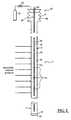
- an optical sensor string 3includes optical sensor elements imbedded or formed within the core of an optical fiber 28 (Fig. 2) which is positioned within a capillary tube 5.
- fiber gratingsBragg gratings
- a measurandsuch as strain induced by pressure, will induce a perturbation of the grating sensor spacing due to overall fiber elongation, and of the refractive index of the glass due to photoelastic effects, which together change the wavelength of the light reflected by the grating.
- the value of the measurandis directly related to the wavelength reflected by the grating and can be determined by detecting the wavelength of the reflected light
- the wavelength encoded nature of the output of fiber gratingshas advantages over intensity based sensing techniques because of the self-referencing nature of the output.
- This sensed informationis encoded directly into the wavelength, which is an absolute parameter and does not depend upon total light levels, losses in fibers or couplers, or variations in source intensity.
- intensity-based sensing schemesdepend upon total light levels and are affected by losses in the connected fibers, by losses in couplers, and by variations in source intensity.
- the optical sensor string 3 and capillary tubing 5are interconnected to optical signal processing equipment 10 via well-known capillary tube delivery equipment (not shown) for delivering the optical sensor string 3 within the capillary tubing 5 down a wellbore 12 of an oil and/or gas well 13.
- the tubing delivery equipmentprovides for the delivery of the capillary tubing 5 and optical sensor string 3 down the wellbore 12, and for the delivery of optical signals between the optical signal processing equipment 10 and the optical sensor string 3 , either directly or via interface equipment (not shown) as required.
- the optical signal processing equipment 10includes, at a minimum, a broadband source of light 11 , such as a light emitting diode (LED), and appropriate light filtering equipment for delivery of signal light to Bragg gratings included within the optical sensor string 3 , as described in greater detail below. Additionally, the optical signal processing equipment 10 includes appropriate optical signal analysis equipment 14 for analyzing the return signals from the Bragg gratings.
- the signal analysis equipmentmay include the necessary hardware and software to implement the optical signal diagnostic equipment disclosed in U.S. Patent Nos. 4,996,419; 5,401,956; 5,426,297; and/or 5,493,390, the disclosures of which are incorporated herein by reference.
- optical signal analysis approacheswhich may be utilized to analyze return signals from optical fiber Bragg gratings. These approaches may be generally classified in the following four categories:
- the particular technique utilizedwill vary, and will depend on the Bragg wavelength shift magnitude (which depends on the sensor sensitivity and measurand strength) and the frequency range of the measurand to be detected.
- the optical signal processing equipmentmay operate on a principle of wave-division multiplexing as described above wherein each bragg grating sensor is utilized at a different passband or frequency band of interest.
- the present inventionmay utilize time-division multiplexing for obtaining signals from multiple independent sensors, or any other suitable means for analyzing signals returned from a plurality of Bragg grating sensors formed in an fiber optic sensor string.
- the senor of the inventionis utilized to measure pressure and/or temperature within the wellbore 12 of the oil and/or gas well 13 .
- casing strings 15Within the wellbore 12 are casing strings 15 , production tubing 18 , and a production packers 20.
- the optical sensor string 3is interconnected via appropriate optical fibers, couplers, etc., to the optical signal processing equipment 10 , which is located above the surface 20 of the wellbore 12 .
- the fiber optic sensor 6 of the inventionincludes an optical fiber 28 which is protected from mechanical damage and corrosive damage by placing it in the rigid wall capillary tube 5 .
- the capillary tubing 5may be made of a high strength, corrosion resistant material, such as stainless steel.
- a distal end 32 of the tube 5is sealed, for example, by welding on an end cap 37 .
- the distal end 32 of the tube 5may be crimped and welded, or other suitable method may be utilized to hermetically seal the end of the tubing to prevent any material from the environment in which the tubing is placed from entering inside of the tubing where the optical fiber and fiber optic sensors are located.
- each Bragg grating 44is constructed so as to reflect a particular wavelength or frequency of light which is propagating along the core, back in the direction of the light source from which it was launched. Each of the particular frequencies is different from the other such that each Bragg grating 44 reflects a unique frequency.
- the Bragg grating sensor string of the inventionrelies on a pressure fluctuation applied to the outside of the fiber, through the capillary tubing, to in turn generate a mechanical strain in the fiber core. Additionally, the sensor string relies on a change in the index of refraction, and to a lesser degree on mechanical strain, caused by thermal expansion/contraction, in response to temperature changes.
- the capillary tube 5is filled with a high density, low compressibility material 48 .
- the high density, low compressibility materialis a liquid, such as water, glycerine, or oil. It is also preferred that the high density, low compressibility material have a high thermal conductivity, such that temperature variations applied to the outside of the capillary tubing are rapidly and accurately transmitted to the Bragg gratings 44 located within the core 40 of the optical fiber 28 .
- the wall of the tubeundergoes a radial displacement which increases or decreases the pressure of the high density, low compressibility material filling the capillary tube 5 .
- This pressureis in turn applied to the optical fiber 28 inside the high density, low compressibility material, thus generating a mechanical strain on the fiber 28 , which modulates the light being guided through the Bragg gratings 44 located within the fiber 28 .
- a sensor manufactured in accordance with the present inventionhas a very low acoustic transmission loss as compared to other devices in the prior art, such as prior art capillary tubes filled with a gas, either at low or high pressure.
- the advantages of the present inventionare best understood by example.
- the following analysiswas performed for two different capillary tubes having an outside diameter of 1 ⁇ 4 inch (0.635 cm).
- One capillary tube (TUBE 1)had a wall thickness of 0.047 inch (0.119 cm) and the other capillary tube (TUBE 2) had a wall thickness of 0.024 inch (0.061 cm).
- the following tableillustrates the attenuation of an acoustic pressure signal of unit strength applied to the outside surface of the tubing.
- the acoustic signalwas transmitted in water over a frequency range of approximately 50 hz to 2 Khz: TUBE AIR AT 1 ATM 1.01x10 5 n/m 2 AIR AT 100 ATM 1.01x10 7 n/m 2 AIR AT 200 ATM 2.03x10 7 n/m 2 Water Glycerin 1 3.5x10 -6 (109 dB) 3.5x10 -4 (69 dB) 7.0x10 -4 (63 dB) 0.006 (44 dB) 0.1 (20 dB) 2 6.5x10 -6 (104 db) 6.3x10 -4 (64 dB) 1.3x10 -3 (58 dB) 0.09 (21 dB) 0.2 (14 dB) As illustrated in the above table, for a capillary tube at one atmosphere of pressure, attenuation of an acoustic signal applied to the outside surface of the tubing causes an approximately 104dB or 109dB attenuation of the acoustic signal, i
- a much improved signal strength of a signal being detected by the sensor of the inventionis provided. Additionally, by using a material having a high thermal conductivity, temperature variations in the environment in which the sensors are located are rapidly and accurately transmitted to the core 40 , such that the pressure signals may be accurately temperature compensated.
- the airhas a thermal conductivity of approximately 0.025 w/m-°k.
- the high density, low compressibility materialssuch as oil, glycerine and water have thermal conductivity of approximately 0.15, 0.3 and 0.35, respectively.
- the high density, low compressibility materialshould have a thermal conductivity greater than approximately 0.1 w/m-°k. Therefore, these materials have substantially improved thermal conductivity and a shorter thermal time constant as compared to prior art air filled capillary tubes. Therefore, the system of the invention has a significantly shorter response time to thermal transients.
- the surface portion of the tubeis provided with a reservoir for receiving excess fluid upon fluid expansion, and for providing fluid to maintain the capillary tubing filled with fluid.
- the reservoirmay be a pressure controlled bellows structure 60 , as illustrated in Fig. 2.
- the bellows structure 60includes an expansion tank or holding tank 61 to hold excess fluid 48 .
- a pressure source 62such as high pressure air, may be provided to maintain the fluid 48 within the bellows structure 60 at a specified pressure, for example by providing a pressure regulator 65 to maintain a specified pressure within the holding tank 61 .
- the pressure within the bellows structure 60may be controlled, for example by use of the regulator 65 , to maintain the fluid 48 in the liquid phase when exposed to high temperatures.
- means 68are provided to allow the optical fiber 28 to pass through the bellows structure 60 while sealing the structure 60 to maintain the desired pressure. As will be understood by those skilled in the art, an excess length of optical fiber 68 is provided to allow expansion and contraction of the bellows structure 60 without damaging or applying excess tension to the optical fiber 28 .
- any suitable method of maintaining material 48 within the capillary tube 5may be used.
- the inventionmay be provided with an overflow reservoir without pressure control. Additionally, if a solid material is utilized, such as a polymer, no overflow is required at all.
- the inventionis described as using fiber Bragg gratings as sensors.
- the Bragg gratingsare essentially described as point sensors.
- any suitable Bragg grating sensor configurationmay be used.
- the Bragg gratingscan be used for interferometric detection wherein a length of optical fiber is positioned between a pair of Bragg grating to thereby form a resonant cavity.
- the Bragg gratingsmay be used to form lazing elements for detection, for example by positioning an Ebrium doped length of optical fiber between a pair of Bragg gratings.
- the present inventionwill work equally as well with other types of sensors located within the capillary tubing.
- the benefits of the present inventionare realized due to improved sensitivity of transmission of environmental pressure and temperature fluctuations to the sensors via the high density, low compressibility material.
- the inventionis described as being used with a hermetically sealed tube to protect the optical fiber and sensors from the harsh environment.
- tube configurationsmay be used with the present invention, such as a "U" shaped tube, wherein both ends of the tube are above the surface of the borehole.
- the tubemay be provided in any desired configuration in the borehole, such as wrapped around the drill string, to place sensors in a desired location within the borehole.
Landscapes
- Physics & Mathematics (AREA)
- General Physics & Mathematics (AREA)
- Optical Transform (AREA)
- Measuring Fluid Pressure (AREA)
- Length Measuring Devices By Optical Means (AREA)
- Measuring Temperature Or Quantity Of Heat (AREA)
- Investigating Or Analysing Materials By Optical Means (AREA)
- Examining Or Testing Airtightness (AREA)
Description
| TUBE | AIR AT 1 ATM 1.01x10⁵n/m2 | AIR AT 100 ATM 1.01x10⁷n/m2 | AIR AT 200 ATM 2.03x10⁷n/m2 | Water | Glycerin |
| 1 | 3.5x10⁻⁶ (109 dB) | 3.5x10⁻⁴ (69 dB) | 7.0x10⁻⁴ (63 dB) | 0.006 (44 dB) | 0.1 (20 dB) |
| 2 | 6.5x10⁻⁶ (104 db) | 6.3x10⁻⁴ (64 dB) | 1.3x10⁻³ (58 dB) | 0.09 (21 dB) | 0.2 (14 dB) |
Claims (24)
- A sensor system for sensing a measurand field in an environment, comprising :wherein said material is responsive to a compressive force exerted on anexternal surface of said capillary tube within the environment for providing a fluidforce, and wherein said sensor elements are responsive to said fluid force and a lightsignal for each providing a sensing light signal indicative of said compressive force.a capillary tubing structure including an array of serially coupled intrinsic fiberoptical sensor elements (44) formed within an optical fiber (28), said sensor elements and saidoptical fiber being deployed within a capillary tube (5), and said capillary tube beingdeployed in the environment; anda high-density, low-compressibility material (48) which completely fills all voidspaces within said capillary tubing structure between an internal surface of saidcapillary tube and said optical fiber, at least in an area of said capillary tube containingsaid sensor elements;
- A sensor system according to claim 1, wherein each one of said sensorelements is a Bragg grating (44) formed in a core of said optical fiber.
- A sensor system according to claim 1, wherein each one of said sensorelements is an interferometer including a respective pair of Bragg gratings formed in acore of said optical fiber and a sensing length of optical fiber positioned between saidrespective pair of Bragg gratings.
- A sensor system according to claim 1, wherein each one of said sensorelements is a lazing element including a respective pair of Bragg gratings formed in acore of said optical fiber and a sensing length of doped optical fiber positionedbetween said respective pair of Bragg gratings.
- A sensor system according to claim 1, wherein said capillarytubing structure is hermetically sealed.
- A sensor system according to claim 1, wherein said material isselected to be thermally conductive so that the temperature in the environment isaccurately and rapidly transmitted through the capillary tube and material to theoptical fiber contained therein.
- A sensor system according to claim 6, wherein the thermalconductivity of said material is greater than 0.1 w/m-°k.
- A sensor system according to claim 1, wherein said material is afluid.
- A sensor system according to claim 8, wherein said fluid isselected from the group consisting of water, glycerine, and oil.
- A sensor system according to claim 8, further comprising reservoir meansfor providing a reservoir for expansion and contraction of said fluid and formaintaining said fluid at a specified pressure.
- A sensor system according to claim 1, wherein said material is apolymer.
- A sensor system according to claim 1, further comprising an opticalsource (11) for providing said light signal, said optical fiber being interconnected to saidoptical source.
- A sensor system according to claim 12, wherein said opticalsource is a light emitting diode.
- A sensor system according to claim 1, wherein said capillary tubeis made of a high strength material which is impervious to penetration by elements inthe environment, said capillary tube being formed of material which is transmissibleto temperature, but which is only slightly compressible and can withstandcompressive forces without collapsing.
- A sensor system according to claim 1, wherein said measurand field isacoustic pressure fluctuations in an environment,characterized by:wherein said intrinsic fiber eptic sensor elements is an array of seriallycoupled intrinsic fiber optic sensors, said sensors being Bragg gratings formed in acore of an optical fiber, said array being interconnected to said optical source by saidoptical fiber.an optical source for providing said light signal; and
- A sensor system according to claim 15, wherein said capillarytubing structure is hermetically sealed.
- A sensor system according to claim 15, wherein said material isselected to be thermally conductive so that the temperature in the environment isaccurately and rapidly transmitted through the capillary tubing and material to thearray,
- A sensor system according to claim 17, wherein the thermalconductivity of said material is greater than 0.1 w/m-°k.
- A sensor system according to claim 15, wherein said material is afluid.
- , A sensor system according to claim 19, wherein said fluid isselected from the group consisting of water, glycerine, and oil.
- A sensor system according to claim 19, further comprising reservoirmeans for providing a reservoir for expansion and contraction of said fluid and formaintaining said fluid at a specified pressure.
- A sensor system according to claim 15, wherein said material is apolymer.
- A sensor system according to claim 15, wherein said opticalsource is a light emitting diode.
- A sensor system according to claim 15, further comprising optical signalprocessing means responsive to each said respective sensing light signal for providingacoustic pressure signals indicative of variations in acoustic pressure in theenvironment adjacent to each said respective sensor element.
Applications Claiming Priority (3)
| Application Number | Priority Date | Filing Date | Title |
|---|---|---|---|
| US777271 | 1996-12-31 | ||
| US08/777,271US5767411A (en) | 1996-12-31 | 1996-12-31 | Apparatus for enhancing strain in intrinsic fiber optic sensors and packaging same for harsh environments |
| PCT/US1997/023980WO1998029717A1 (en) | 1996-12-31 | 1997-12-19 | Apparatus for enhancing strain in intrinsic fiber optic sensors and packaging same for harsh environments |
Publications (2)
| Publication Number | Publication Date |
|---|---|
| EP0950170A1 EP0950170A1 (en) | 1999-10-20 |
| EP0950170B1true EP0950170B1 (en) | 2002-09-11 |
Family
ID=25109782
Family Applications (1)
| Application Number | Title | Priority Date | Filing Date |
|---|---|---|---|
| EP97953481AExpired - LifetimeEP0950170B1 (en) | 1996-12-31 | 1997-12-19 | Apparatus for enhancing strain in intrinsic fiber optic sensors and packaging same for harsh environments |
Country Status (10)
| Country | Link |
|---|---|
| US (1) | US5767411A (en) |
| EP (1) | EP0950170B1 (en) |
| AR (1) | AR008552A1 (en) |
| AU (1) | AU5722098A (en) |
| CA (1) | CA2276449C (en) |
| CO (1) | CO4771128A1 (en) |
| DE (1) | DE69715455T2 (en) |
| NO (1) | NO320490B1 (en) |
| PE (1) | PE30599A1 (en) |
| WO (1) | WO1998029717A1 (en) |
Cited By (27)
| Publication number | Priority date | Publication date | Assignee | Title |
|---|---|---|---|---|
| US7490664B2 (en) | 2004-11-12 | 2009-02-17 | Halliburton Energy Services, Inc. | Drilling, perforating and formation analysis |
| US8424617B2 (en) | 2008-08-20 | 2013-04-23 | Foro Energy Inc. | Methods and apparatus for delivering high power laser energy to a surface |
| US8464794B2 (en) | 2009-06-29 | 2013-06-18 | Halliburton Energy Services, Inc. | Wellbore laser operations |
| US8571368B2 (en) | 2010-07-21 | 2013-10-29 | Foro Energy, Inc. | Optical fiber configurations for transmission of laser energy over great distances |
| US8627901B1 (en) | 2009-10-01 | 2014-01-14 | Foro Energy, Inc. | Laser bottom hole assembly |
| US8662160B2 (en) | 2008-08-20 | 2014-03-04 | Foro Energy Inc. | Systems and conveyance structures for high power long distance laser transmission |
| US8684088B2 (en) | 2011-02-24 | 2014-04-01 | Foro Energy, Inc. | Shear laser module and method of retrofitting and use |
| US8720584B2 (en) | 2011-02-24 | 2014-05-13 | Foro Energy, Inc. | Laser assisted system for controlling deep water drilling emergency situations |
| US8783360B2 (en) | 2011-02-24 | 2014-07-22 | Foro Energy, Inc. | Laser assisted riser disconnect and method of use |
| US8783361B2 (en) | 2011-02-24 | 2014-07-22 | Foro Energy, Inc. | Laser assisted blowout preventer and methods of use |
| US9027668B2 (en) | 2008-08-20 | 2015-05-12 | Foro Energy, Inc. | Control system for high power laser drilling workover and completion unit |
| US9074422B2 (en) | 2011-02-24 | 2015-07-07 | Foro Energy, Inc. | Electric motor for laser-mechanical drilling |
| US9080425B2 (en) | 2008-10-17 | 2015-07-14 | Foro Energy, Inc. | High power laser photo-conversion assemblies, apparatuses and methods of use |
| US9089928B2 (en) | 2008-08-20 | 2015-07-28 | Foro Energy, Inc. | Laser systems and methods for the removal of structures |
| US9138786B2 (en) | 2008-10-17 | 2015-09-22 | Foro Energy, Inc. | High power laser pipeline tool and methods of use |
| US9244235B2 (en) | 2008-10-17 | 2016-01-26 | Foro Energy, Inc. | Systems and assemblies for transferring high power laser energy through a rotating junction |
| US9242309B2 (en) | 2012-03-01 | 2016-01-26 | Foro Energy Inc. | Total internal reflection laser tools and methods |
| US9267330B2 (en) | 2008-08-20 | 2016-02-23 | Foro Energy, Inc. | Long distance high power optical laser fiber break detection and continuity monitoring systems and methods |
| US9347271B2 (en) | 2008-10-17 | 2016-05-24 | Foro Energy, Inc. | Optical fiber cable for transmission of high power laser energy over great distances |
| US9360643B2 (en) | 2011-06-03 | 2016-06-07 | Foro Energy, Inc. | Rugged passively cooled high power laser fiber optic connectors and methods of use |
| US9360631B2 (en) | 2008-08-20 | 2016-06-07 | Foro Energy, Inc. | Optics assembly for high power laser tools |
| US9562395B2 (en) | 2008-08-20 | 2017-02-07 | Foro Energy, Inc. | High power laser-mechanical drilling bit and methods of use |
| US9664012B2 (en) | 2008-08-20 | 2017-05-30 | Foro Energy, Inc. | High power laser decomissioning of multistring and damaged wells |
| US9669492B2 (en) | 2008-08-20 | 2017-06-06 | Foro Energy, Inc. | High power laser offshore decommissioning tool, system and methods of use |
| US9719302B2 (en) | 2008-08-20 | 2017-08-01 | Foro Energy, Inc. | High power laser perforating and laser fracturing tools and methods of use |
| US9845652B2 (en) | 2011-02-24 | 2017-12-19 | Foro Energy, Inc. | Reduced mechanical energy well control systems and methods of use |
| CN108917830A (en)* | 2018-06-19 | 2018-11-30 | 杭州市质量技术监督检测院 | A kind of intelligent wall with self-induction function |
Families Citing this family (47)
| Publication number | Priority date | Publication date | Assignee | Title |
|---|---|---|---|---|
| US6072567A (en)* | 1997-02-12 | 2000-06-06 | Cidra Corporation | Vertical seismic profiling system having vertical seismic profiling optical signal processing equipment and fiber Bragg grafting optical sensors |
| US6074503A (en) | 1997-04-22 | 2000-06-13 | Cable Design Technologies, Inc. | Making enhanced data cable with cross-twist cabled core profile |
| US6787758B2 (en)* | 2001-02-06 | 2004-09-07 | Baker Hughes Incorporated | Wellbores utilizing fiber optic-based sensors and operating devices |
| US6016702A (en)* | 1997-09-08 | 2000-01-25 | Cidra Corporation | High sensitivity fiber optic pressure sensor for use in harsh environments |
| US6058226A (en)* | 1997-10-24 | 2000-05-02 | D-Star Technologies Llc | Optical fiber sensors, tunable filters and modulators using long-period gratings |
| US6522797B1 (en) | 1998-09-01 | 2003-02-18 | Input/Output, Inc. | Seismic optical acoustic recursive sensor system |
| JP4615726B2 (en) | 1998-12-04 | 2011-01-19 | ウェザーフォード/ラム インコーポレーテッド | Bragg grating pressure sensor |
| BR9915956B1 (en) | 1998-12-04 | 2011-10-18 | pressure sensor, and method for sensing pressure. | |
| US6222973B1 (en) | 1999-01-15 | 2001-04-24 | D-Star Technologies, Inc. | Fabrication of refractive index patterns in optical fibers having protective optical coatings |
| US6528239B1 (en) | 1999-01-15 | 2003-03-04 | Sabeus Photonics, Inc. | Method of forming a grating in a waveguide |
| US6148925A (en) | 1999-02-12 | 2000-11-21 | Moore; Boyd B. | Method of making a conductive downhole wire line system |
| US6233746B1 (en) | 1999-03-22 | 2001-05-22 | Halliburton Energy Services, Inc. | Multiplexed fiber optic transducer for use in a well and method |
| FR2791768B1 (en)* | 1999-04-01 | 2001-04-20 | Commissariat Energie Atomique | BRAGG NETWORK EXTENSOMETER AND MANUFACTURING METHOD THEREOF |
| DE19938978A1 (en)* | 1999-08-19 | 2001-02-22 | Abb Research Ltd | Fibre optic pressure sensor has fibre-Bragg grids with approximately equal gas sensitivity; thermally induced Bragg wavelength displacements of at least 2 grids have predefined relationship |
| US6439055B1 (en) | 1999-11-15 | 2002-08-27 | Weatherford/Lamb, Inc. | Pressure sensor assembly structure to insulate a pressure sensing device from harsh environments |
| AU782553B2 (en)* | 2000-01-05 | 2005-08-11 | Baker Hughes Incorporated | Method of providing hydraulic/fiber conduits adjacent bottom hole assemblies for multi-step completions |
| US6626043B1 (en)* | 2000-01-31 | 2003-09-30 | Weatherford/Lamb, Inc. | Fluid diffusion resistant glass-encased fiber optic sensor |
| KR100368122B1 (en)* | 2000-05-04 | 2003-01-15 | 병 호 이 | Chirped fiber grating sensor with variable reflection bandwidth according to strain and strain measurement system using the sensor |
| US6601671B1 (en)* | 2000-07-10 | 2003-08-05 | Weatherford/Lamb, Inc. | Method and apparatus for seismically surveying an earth formation in relation to a borehole |
| GB0021976D0 (en)* | 2000-09-07 | 2000-10-25 | Optomed As | Multi-parameter fiber optic probes |
| NO315762B1 (en)* | 2000-09-12 | 2003-10-20 | Optoplan As | Sand detector |
| US20040042703A1 (en)* | 2002-08-28 | 2004-03-04 | Deaton Thomas M. | Method and apparatus for sensing an environmental parameter in a wellbore |
| US6978832B2 (en) | 2002-09-09 | 2005-12-27 | Halliburton Energy Services, Inc. | Downhole sensing with fiber in the formation |
| US6847034B2 (en)* | 2002-09-09 | 2005-01-25 | Halliburton Energy Services, Inc. | Downhole sensing with fiber in exterior annulus |
| US20040065437A1 (en)* | 2002-10-06 | 2004-04-08 | Weatherford/Lamb Inc. | In-well seismic sensor casing coupling using natural forces in wells |
| US6888972B2 (en)* | 2002-10-06 | 2005-05-03 | Weatherford/Lamb, Inc. | Multiple component sensor mechanism |
| GB2396211B (en) | 2002-10-06 | 2006-02-22 | Weatherford Lamb | Multiple component sensor mechanism |
| US7036601B2 (en) | 2002-10-06 | 2006-05-02 | Weatherford/Lamb, Inc. | Apparatus and method for transporting, deploying, and retrieving arrays having nodes interconnected by sections of cable |
| US7219729B2 (en)* | 2002-11-05 | 2007-05-22 | Weatherford/Lamb, Inc. | Permanent downhole deployment of optical sensors |
| US6915686B2 (en) | 2003-02-11 | 2005-07-12 | Optoplan A.S. | Downhole sub for instrumentation |
| US7159653B2 (en) | 2003-02-27 | 2007-01-09 | Weatherford/Lamb, Inc. | Spacer sub |
| US6840114B2 (en)* | 2003-05-19 | 2005-01-11 | Weatherford/Lamb, Inc. | Housing on the exterior of a well casing for optical fiber sensors |
| US6957574B2 (en) | 2003-05-19 | 2005-10-25 | Weatherford/Lamb, Inc. | Well integrity monitoring system |
| US7397976B2 (en)* | 2005-01-25 | 2008-07-08 | Vetco Gray Controls Limited | Fiber optic sensor and sensing system for hydrocarbon flow |
| US8186428B2 (en)* | 2007-04-03 | 2012-05-29 | Baker Hughes Incorporated | Fiber support arrangement for a downhole tool and method |
| US7912334B2 (en)* | 2007-09-19 | 2011-03-22 | General Electric Company | Harsh environment temperature sensing system and method |
| WO2011012406A1 (en)* | 2009-07-30 | 2011-02-03 | Hottinger Baldwin Messtechnik Gmbh | Device and method for the spatially-resolved recording of ground motion |
| US8662165B2 (en) | 2010-07-06 | 2014-03-04 | Baker Hughes Incorporated | Fiber support arrangement and method |
| US8542955B2 (en)* | 2010-10-28 | 2013-09-24 | General Electric Company | Gas detection system incorporating fiber gas sensors having fiber bragg gratings |
| US20140327919A1 (en)* | 2013-05-06 | 2014-11-06 | Halliburton Energy Services. Inc. | Remote Seal for Pressure Sensor |
| CN103953330B (en)* | 2014-04-02 | 2016-09-14 | 北京博简复才技术咨询有限公司 | Deep-well oil-gas Layer temperature and pressure Online integration monitoring device and method |
| US9624763B2 (en) | 2014-09-29 | 2017-04-18 | Baker Hughes Incorporated | Downhole health monitoring system and method |
| US9448312B1 (en) | 2015-03-11 | 2016-09-20 | Baker Hughes Incorporated | Downhole fiber optic sensors with downhole optical interrogator |
| NL2015952B1 (en)* | 2015-12-11 | 2017-07-03 | Fugro Tech Bv | Pressure sensor and sensor system comprising one or more pressure sensors. |
| CN105725982A (en)* | 2016-01-25 | 2016-07-06 | 东华大学 | Shoe sole pressure and temperature measuring insole based on optical fiber sensing technology |
| US20200152354A1 (en)* | 2018-11-14 | 2020-05-14 | Minnesota Wire | Integrated circuits in cable |
| CN114252649B (en)* | 2021-12-30 | 2024-08-23 | 中北大学 | Optical fiber fluid flow velocity detection device |
Family Cites Families (30)
| Publication number | Priority date | Publication date | Assignee | Title |
|---|---|---|---|---|
| US4235113A (en)* | 1978-08-21 | 1980-11-25 | Carome Edward F | Optical fiber acoustical sensors |
| EP0066493A1 (en)* | 1981-05-15 | 1982-12-08 | Schlumberger Limited | Pressure wave fiber optic transducer cable |
| US5363463A (en)* | 1982-08-06 | 1994-11-08 | Kleinerman Marcos Y | Remote sensing of physical variables with fiber optic systems |
| US4547869A (en)* | 1983-04-04 | 1985-10-15 | Western Geophysical Company Of America | Marine seismic sensor |
| US5625605A (en)* | 1983-09-13 | 1997-04-29 | The United States Of America As Represented By The Secretary Of The Navy | Optic bundle towed array |
| US5574699A (en)* | 1983-10-31 | 1996-11-12 | Cuomo; Frank W. | Fiber optic lever towed array |
| US4761073A (en)* | 1984-08-13 | 1988-08-02 | United Technologies Corporation | Distributed, spatially resolving optical fiber strain gauge |
| US4589285A (en)* | 1984-11-05 | 1986-05-20 | Western Geophysical Co. Of America | Wavelength-division-multiplexed receiver array for vertical seismic profiling |
| WO1987002453A1 (en)* | 1985-10-21 | 1987-04-23 | Plessey Overseas Limited | Sensing system using fibre optic sensors |
| US4649529A (en)* | 1985-12-02 | 1987-03-10 | Exxon Production Research Co. | Multi-channel fiber optic sensor system |
| US4722603A (en)* | 1986-06-27 | 1988-02-02 | Chevron Research Company | Interferometric means and method for accurate determination of fiber-optic well logging cable length |
| US5163321A (en)* | 1989-10-17 | 1992-11-17 | Baroid Technology, Inc. | Borehole pressure and temperature measurement system |
| US4996419A (en)* | 1989-12-26 | 1991-02-26 | United Technologies Corporation | Distributed multiplexed optical fiber Bragg grating sensor arrangeement |
| US5227857A (en)* | 1991-04-24 | 1993-07-13 | The United States Of America As Represented By The Secretary Of The Navy | System for cancelling phase noise in an interferometric fiber optic sensor arrangement |
| US5275038A (en)* | 1991-05-20 | 1994-01-04 | Otis Engineering Corporation | Downhole reeled tubing inspection system with fiberoptic cable |
| US5485745A (en)* | 1991-05-20 | 1996-01-23 | Halliburton Company | Modular downhole inspection system for coiled tubing |
| US5397891A (en)* | 1992-10-20 | 1995-03-14 | Mcdonnell Douglas Corporation | Sensor systems employing optical fiber gratings |
| US5380995A (en)* | 1992-10-20 | 1995-01-10 | Mcdonnell Douglas Corporation | Fiber optic grating sensor systems for sensing environmental effects |
| US5361130A (en)* | 1992-11-04 | 1994-11-01 | The United States Of America As Represented By The Secretary Of The Navy | Fiber grating-based sensing system with interferometric wavelength-shift detection |
| EP0601811B1 (en)* | 1992-12-07 | 1997-10-01 | Akishima Laboratories (Mitsui Zosen) Inc. | Measurement-while-drilling system using mud-pulse valve for data transmission |
| KR960007884B1 (en)* | 1993-04-24 | 1996-06-15 | 국방과학연구소 | Optical fiber |
| IT1262407B (en)* | 1993-09-06 | 1996-06-19 | Finmeccanica Spa | INSTRUMENTATION USING INTEGRATED OPTIC COMPONENTS FOR DIAGNOSTICS OF PARTS WITH FIBER OPTIC SENSORS INCLUDED OR FIXED ON THE SURFACE. |
| US5426297A (en)* | 1993-09-27 | 1995-06-20 | United Technologies Corporation | Multiplexed Bragg grating sensors |
| US5401956A (en)* | 1993-09-29 | 1995-03-28 | United Technologies Corporation | Diagnostic system for fiber grating sensors |
| US5400427A (en)* | 1993-10-18 | 1995-03-21 | Mobil Oil Corporation | Fiber optic cable and viscous filler material |
| DE4337402A1 (en)* | 1993-10-26 | 1995-04-27 | Mannesmann Ag | Probe for measuring pressure and temperature profiles |
| US5410404A (en)* | 1993-11-30 | 1995-04-25 | The United States Of America As Represented By The Secretary Of The Navy | Fiber grating-based detection system for wavelength encoded fiber sensors |
| US5451772A (en)* | 1994-01-13 | 1995-09-19 | Mechanical Technology Incorporated | Distributed fiber optic sensor |
| US5493113A (en)* | 1994-11-29 | 1996-02-20 | United Technologies Corporation | Highly sensitive optical fiber cavity coating removal detection |
| US5675674A (en)* | 1995-08-24 | 1997-10-07 | Rockbit International | Optical fiber modulation and demodulation system |
- 1996
- 1996-12-31USUS08/777,271patent/US5767411A/ennot_activeExpired - Lifetime
- 1997
- 1997-12-19AUAU57220/98Apatent/AU5722098A/ennot_activeAbandoned
- 1997-12-19EPEP97953481Apatent/EP0950170B1/ennot_activeExpired - Lifetime
- 1997-12-19CACA002276449Apatent/CA2276449C/ennot_activeExpired - Fee Related
- 1997-12-19WOPCT/US1997/023980patent/WO1998029717A1/enactiveIP Right Grant
- 1997-12-19DEDE69715455Tpatent/DE69715455T2/ennot_activeExpired - Lifetime
- 1997-12-23COCO97074671Apatent/CO4771128A1/enunknown
- 1997-12-24PEPE1997001164Apatent/PE30599A1/ennot_activeApplication Discontinuation
- 1997-12-30ARARP970106278Apatent/AR008552A1/enunknown
- 1999
- 1999-06-29NONO993222Apatent/NO320490B1/ennot_activeIP Right Cessation
Cited By (47)
| Publication number | Priority date | Publication date | Assignee | Title |
|---|---|---|---|---|
| US7490664B2 (en) | 2004-11-12 | 2009-02-17 | Halliburton Energy Services, Inc. | Drilling, perforating and formation analysis |
| US7938175B2 (en) | 2004-11-12 | 2011-05-10 | Halliburton Energy Services Inc. | Drilling, perforating and formation analysis |
| US9284783B1 (en) | 2008-08-20 | 2016-03-15 | Foro Energy, Inc. | High power laser energy distribution patterns, apparatus and methods for creating wells |
| US8936108B2 (en) | 2008-08-20 | 2015-01-20 | Foro Energy, Inc. | High power laser downhole cutting tools and systems |
| US8511401B2 (en) | 2008-08-20 | 2013-08-20 | Foro Energy, Inc. | Method and apparatus for delivering high power laser energy over long distances |
| US10036232B2 (en) | 2008-08-20 | 2018-07-31 | Foro Energy | Systems and conveyance structures for high power long distance laser transmission |
| US9719302B2 (en) | 2008-08-20 | 2017-08-01 | Foro Energy, Inc. | High power laser perforating and laser fracturing tools and methods of use |
| US9669492B2 (en) | 2008-08-20 | 2017-06-06 | Foro Energy, Inc. | High power laser offshore decommissioning tool, system and methods of use |
| US9664012B2 (en) | 2008-08-20 | 2017-05-30 | Foro Energy, Inc. | High power laser decomissioning of multistring and damaged wells |
| US9562395B2 (en) | 2008-08-20 | 2017-02-07 | Foro Energy, Inc. | High power laser-mechanical drilling bit and methods of use |
| US8636085B2 (en) | 2008-08-20 | 2014-01-28 | Foro Energy, Inc. | Methods and apparatus for removal and control of material in laser drilling of a borehole |
| US8662160B2 (en) | 2008-08-20 | 2014-03-04 | Foro Energy Inc. | Systems and conveyance structures for high power long distance laser transmission |
| US9360631B2 (en) | 2008-08-20 | 2016-06-07 | Foro Energy, Inc. | Optics assembly for high power laser tools |
| US8997894B2 (en) | 2008-08-20 | 2015-04-07 | Foro Energy, Inc. | Method and apparatus for delivering high power laser energy over long distances |
| US8701794B2 (en) | 2008-08-20 | 2014-04-22 | Foro Energy, Inc. | High power laser perforating tools and systems |
| US8424617B2 (en) | 2008-08-20 | 2013-04-23 | Foro Energy Inc. | Methods and apparatus for delivering high power laser energy to a surface |
| US8757292B2 (en) | 2008-08-20 | 2014-06-24 | Foro Energy, Inc. | Methods for enhancing the efficiency of creating a borehole using high power laser systems |
| US9027668B2 (en) | 2008-08-20 | 2015-05-12 | Foro Energy, Inc. | Control system for high power laser drilling workover and completion unit |
| US9267330B2 (en) | 2008-08-20 | 2016-02-23 | Foro Energy, Inc. | Long distance high power optical laser fiber break detection and continuity monitoring systems and methods |
| US8820434B2 (en) | 2008-08-20 | 2014-09-02 | Foro Energy, Inc. | Apparatus for advancing a wellbore using high power laser energy |
| US8826973B2 (en) | 2008-08-20 | 2014-09-09 | Foro Energy, Inc. | Method and system for advancement of a borehole using a high power laser |
| US8869914B2 (en) | 2008-08-20 | 2014-10-28 | Foro Energy, Inc. | High power laser workover and completion tools and systems |
| US9089928B2 (en) | 2008-08-20 | 2015-07-28 | Foro Energy, Inc. | Laser systems and methods for the removal of structures |
| US9347271B2 (en) | 2008-10-17 | 2016-05-24 | Foro Energy, Inc. | Optical fiber cable for transmission of high power laser energy over great distances |
| US9327810B2 (en) | 2008-10-17 | 2016-05-03 | Foro Energy, Inc. | High power laser ROV systems and methods for treating subsea structures |
| US9080425B2 (en) | 2008-10-17 | 2015-07-14 | Foro Energy, Inc. | High power laser photo-conversion assemblies, apparatuses and methods of use |
| US9138786B2 (en) | 2008-10-17 | 2015-09-22 | Foro Energy, Inc. | High power laser pipeline tool and methods of use |
| US9244235B2 (en) | 2008-10-17 | 2016-01-26 | Foro Energy, Inc. | Systems and assemblies for transferring high power laser energy through a rotating junction |
| US8528643B2 (en) | 2009-06-29 | 2013-09-10 | Halliburton Energy Services, Inc. | Wellbore laser operations |
| US8534357B2 (en) | 2009-06-29 | 2013-09-17 | Halliburton Energy Services, Inc. | Wellbore laser operations |
| US8540026B2 (en) | 2009-06-29 | 2013-09-24 | Halliburton Energy Services, Inc. | Wellbore laser operations |
| US8464794B2 (en) | 2009-06-29 | 2013-06-18 | Halliburton Energy Services, Inc. | Wellbore laser operations |
| US8678087B2 (en) | 2009-06-29 | 2014-03-25 | Halliburton Energy Services, Inc. | Wellbore laser operations |
| US8627901B1 (en) | 2009-10-01 | 2014-01-14 | Foro Energy, Inc. | Laser bottom hole assembly |
| US8571368B2 (en) | 2010-07-21 | 2013-10-29 | Foro Energy, Inc. | Optical fiber configurations for transmission of laser energy over great distances |
| US8879876B2 (en) | 2010-07-21 | 2014-11-04 | Foro Energy, Inc. | Optical fiber configurations for transmission of laser energy over great distances |
| US9784037B2 (en) | 2011-02-24 | 2017-10-10 | Daryl L. Grubb | Electric motor for laser-mechanical drilling |
| US8783361B2 (en) | 2011-02-24 | 2014-07-22 | Foro Energy, Inc. | Laser assisted blowout preventer and methods of use |
| US8684088B2 (en) | 2011-02-24 | 2014-04-01 | Foro Energy, Inc. | Shear laser module and method of retrofitting and use |
| US9074422B2 (en) | 2011-02-24 | 2015-07-07 | Foro Energy, Inc. | Electric motor for laser-mechanical drilling |
| US8720584B2 (en) | 2011-02-24 | 2014-05-13 | Foro Energy, Inc. | Laser assisted system for controlling deep water drilling emergency situations |
| US9291017B2 (en) | 2011-02-24 | 2016-03-22 | Foro Energy, Inc. | Laser assisted system for controlling deep water drilling emergency situations |
| US9845652B2 (en) | 2011-02-24 | 2017-12-19 | Foro Energy, Inc. | Reduced mechanical energy well control systems and methods of use |
| US8783360B2 (en) | 2011-02-24 | 2014-07-22 | Foro Energy, Inc. | Laser assisted riser disconnect and method of use |
| US9360643B2 (en) | 2011-06-03 | 2016-06-07 | Foro Energy, Inc. | Rugged passively cooled high power laser fiber optic connectors and methods of use |
| US9242309B2 (en) | 2012-03-01 | 2016-01-26 | Foro Energy Inc. | Total internal reflection laser tools and methods |
| CN108917830A (en)* | 2018-06-19 | 2018-11-30 | 杭州市质量技术监督检测院 | A kind of intelligent wall with self-induction function |
Also Published As
| Publication number | Publication date |
|---|---|
| PE30599A1 (en) | 1999-03-19 |
| AU5722098A (en) | 1998-07-31 |
| CA2276449A1 (en) | 1998-07-09 |
| NO993222L (en) | 1999-06-29 |
| NO993222D0 (en) | 1999-06-29 |
| CA2276449C (en) | 2007-07-03 |
| US5767411A (en) | 1998-06-16 |
| WO1998029717A1 (en) | 1998-07-09 |
| NO320490B1 (en) | 2005-12-12 |
| DE69715455D1 (en) | 2002-10-17 |
| CO4771128A1 (en) | 1999-04-30 |
| AR008552A1 (en) | 2000-01-19 |
| EP0950170A1 (en) | 1999-10-20 |
| DE69715455T2 (en) | 2003-05-28 |
Similar Documents
| Publication | Publication Date | Title |
|---|---|---|
| EP0950170B1 (en) | Apparatus for enhancing strain in intrinsic fiber optic sensors and packaging same for harsh environments | |
| US8805128B2 (en) | Multi-point pressure sensor and uses thereof | |
| US6191414B1 (en) | Composite form as a component for a pressure transducer | |
| US5892860A (en) | Multi-parameter fiber optic sensor for use in harsh environments | |
| US5925879A (en) | Oil and gas well packer having fiber optic Bragg Grating sensors for downhole insitu inflation monitoring | |
| US5844667A (en) | Fiber optic pressure sensor with passive temperature compensation | |
| EP1012553B1 (en) | High sensitivity fiber optic pressure sensor for use in harsh environments | |
| US7437027B2 (en) | Isolated sensor housing | |
| US6854327B2 (en) | Apparatus and method for monitoring compaction | |
| US6246048B1 (en) | Methods and apparatus for mechanically enhancing the sensitivity of longitudinally loaded fiber optic sensors | |
| US6072567A (en) | Vertical seismic profiling system having vertical seismic profiling optical signal processing equipment and fiber Bragg grafting optical sensors | |
| CA2461437C (en) | Pressure compensated hydrophone | |
| US5118931A (en) | Fiber optic microbending sensor arrays including microbend sensors sensitive over different bands of wavelengths of light | |
| US6218661B1 (en) | Methods and apparatus for mechanically enhancing the sensitivity of transversely loaded fiber optic sensors | |
| US5877426A (en) | Bourdon tube pressure gauge with integral optical strain sensors for measuring tension or compressive strain | |
| CA2237197C (en) | Sensor arrangement | |
| Yamate | Thermally insensitive pressure measurements up to 300 degree C using fiber Bragg gratings written onto side hole single mode fiber | |
| WO2000003217A2 (en) | Composite form as a component for a pressure transducer | |
| Udd | Thermally Insensitive Pressure Measurements up to 300 degree C Using Fiber Bragg Gratings Written onto Side Hole Single Mode Fiber Tsutomu Yamate, Rogerio T. Ramos and Robert J. Schroeder Schlumberger-Doll Research | |
| Kersey et al. | MONITORING TECHNIQUES |
Legal Events
| Date | Code | Title | Description |
|---|---|---|---|
| PUAI | Public reference made under article 153(3) epc to a published international application that has entered the european phase | Free format text:ORIGINAL CODE: 0009012 | |
| 17P | Request for examination filed | Effective date:19990721 | |
| AK | Designated contracting states | Kind code of ref document:A1 Designated state(s):DE FR GB | |
| GRAG | Despatch of communication of intention to grant | Free format text:ORIGINAL CODE: EPIDOS AGRA | |
| 17Q | First examination report despatched | Effective date:20010823 | |
| GRAG | Despatch of communication of intention to grant | Free format text:ORIGINAL CODE: EPIDOS AGRA | |
| GRAH | Despatch of communication of intention to grant a patent | Free format text:ORIGINAL CODE: EPIDOS IGRA | |
| GRAH | Despatch of communication of intention to grant a patent | Free format text:ORIGINAL CODE: EPIDOS IGRA | |
| RAP1 | Party data changed (applicant data changed or rights of an application transferred) | Owner name:WEATHERFORD/LAMB, INC. | |
| GRAA | (expected) grant | Free format text:ORIGINAL CODE: 0009210 | |
| AK | Designated contracting states | Kind code of ref document:B1 Designated state(s):DE FR GB | |
| REG | Reference to a national code | Ref country code:GB Ref legal event code:FG4D | |
| REF | Corresponds to: | Ref document number:69715455 Country of ref document:DE Date of ref document:20021017 | |
| ET | Fr: translation filed | ||
| PLBE | No opposition filed within time limit | Free format text:ORIGINAL CODE: 0009261 | |
| STAA | Information on the status of an ep patent application or granted ep patent | Free format text:STATUS: NO OPPOSITION FILED WITHIN TIME LIMIT | |
| 26N | No opposition filed | Effective date:20030612 | |
| REG | Reference to a national code | Ref country code:DE Ref legal event code:R081 Ref document number:69715455 Country of ref document:DE Owner name:WEATHERFORD TECHNOLOGY HOLDINGS, LLC, HOUSTON, US Free format text:FORMER OWNER: WEATHERFORD/LAMB, INC., HOUSTON, TEX., US Effective date:20150417 | |
| REG | Reference to a national code | Ref country code:FR Ref legal event code:TP Owner name:WEATHERFORD TECHNOLOGY HOLDINGS, LLC, US Effective date:20150603 | |
| REG | Reference to a national code | Ref country code:FR Ref legal event code:PLFP Year of fee payment:19 | |
| REG | Reference to a national code | Ref country code:GB Ref legal event code:732E Free format text:REGISTERED BETWEEN 20151022 AND 20151028 | |
| PGFP | Annual fee paid to national office [announced via postgrant information from national office to epo] | Ref country code:DE Payment date:20151215 Year of fee payment:19 Ref country code:GB Payment date:20151216 Year of fee payment:19 | |
| PGFP | Annual fee paid to national office [announced via postgrant information from national office to epo] | Ref country code:FR Payment date:20151110 Year of fee payment:19 | |
| REG | Reference to a national code | Ref country code:DE Ref legal event code:R119 Ref document number:69715455 Country of ref document:DE | |
| GBPC | Gb: european patent ceased through non-payment of renewal fee | Effective date:20161219 | |
| REG | Reference to a national code | Ref country code:FR Ref legal event code:ST Effective date:20170831 | |
| PG25 | Lapsed in a contracting state [announced via postgrant information from national office to epo] | Ref country code:FR Free format text:LAPSE BECAUSE OF NON-PAYMENT OF DUE FEES Effective date:20170102 | |
| PG25 | Lapsed in a contracting state [announced via postgrant information from national office to epo] | Ref country code:DE Free format text:LAPSE BECAUSE OF NON-PAYMENT OF DUE FEES Effective date:20170701 Ref country code:GB Free format text:LAPSE BECAUSE OF NON-PAYMENT OF DUE FEES Effective date:20161219 |