EP0941743A2 - Adapter for mounting a fluid handling device on a catheter tubing - Google Patents
Adapter for mounting a fluid handling device on a catheter tubingDownload PDFInfo
- Publication number
- EP0941743A2 EP0941743A2EP99103732AEP99103732AEP0941743A2EP 0941743 A2EP0941743 A2EP 0941743A2EP 99103732 AEP99103732 AEP 99103732AEP 99103732 AEP99103732 AEP 99103732AEP 0941743 A2EP0941743 A2EP 0941743A2
- Authority
- EP
- European Patent Office
- Prior art keywords
- catheter
- adapter
- passageway
- collar
- retainer
- Prior art date
- Legal status (The legal status is an assumption and is not a legal conclusion. Google has not performed a legal analysis and makes no representation as to the accuracy of the status listed.)
- Granted
Links
- 239000012530fluidSubstances0.000titleclaimsabstractdescription32
- 229920002943EPDM rubberPolymers0.000claimsdescription4
- 239000013536elastomeric materialSubstances0.000claimsdescription4
- 239000012815thermoplastic materialSubstances0.000claimsdescription4
- 229930182556PolyacetalNatural products0.000claimsdescription3
- 239000004952PolyamideSubstances0.000claimsdescription3
- 239000004743PolypropyleneSubstances0.000claimsdescription3
- 239000004793PolystyreneSubstances0.000claimsdescription3
- 229920002492poly(sulfone)Polymers0.000claimsdescription3
- 229920000058polyacrylatePolymers0.000claimsdescription3
- 229920002647polyamidePolymers0.000claimsdescription3
- 229920000515polycarbonatePolymers0.000claimsdescription3
- 239000004417polycarbonateSubstances0.000claimsdescription3
- 229920006324polyoxymethylenePolymers0.000claimsdescription3
- -1polypropylenePolymers0.000claimsdescription3
- 229920001155polypropylenePolymers0.000claimsdescription3
- 229920002223polystyrenePolymers0.000claimsdescription3
- 244000043261Hevea brasiliensisSpecies0.000claimsdescription2
- 229920003052natural elastomerPolymers0.000claimsdescription2
- 229920001194natural rubberPolymers0.000claimsdescription2
- 229920002379silicone rubberPolymers0.000claimsdescription2
- 239000012780transparent materialSubstances0.000claimsdescription2
- 230000037431insertionEffects0.000claims1
- 238000003780insertionMethods0.000claims1
- 238000000034methodMethods0.000description14
- 239000000463materialSubstances0.000description8
- 239000007769metal materialSubstances0.000description4
- 230000003444anaesthetic effectEffects0.000description3
- 239000003814drugSubstances0.000description3
- 244000005700microbiomeSpecies0.000description3
- 229920001169thermoplasticPolymers0.000description3
- 239000004416thermosoftening plasticSubstances0.000description3
- 239000003795chemical substances by applicationSubstances0.000description2
- 239000002184metalSubstances0.000description2
- IAYPIBMASNFSPL-UHFFFAOYSA-NEthylene oxideChemical compoundC1CO1IAYPIBMASNFSPL-UHFFFAOYSA-N0.000description1
- 238000004026adhesive bondingMethods0.000description1
- 230000000202analgesic effectEffects0.000description1
- 239000002131composite materialSubstances0.000description1
- 229940079593drugDrugs0.000description1
- 239000011888foilSubstances0.000description1
- 238000009472formulationMethods0.000description1
- 230000003993interactionEffects0.000description1
- 238000001990intravenous administrationMethods0.000description1
- 230000005865ionizing radiationEffects0.000description1
- 210000003127kneeAnatomy0.000description1
- 238000005555metalworkingMethods0.000description1
- 239000000203mixtureSubstances0.000description1
- 239000004745nonwoven fabricSubstances0.000description1
- 239000000123paperSubstances0.000description1
- 230000035515penetrationEffects0.000description1
- 230000002265preventionEffects0.000description1
- 238000009877renderingMethods0.000description1
- 230000000717retained effectEffects0.000description1
- 239000002904solventSubstances0.000description1
- 238000002693spinal anesthesiaMethods0.000description1
- 230000001954sterilising effectEffects0.000description1
- 238000004659sterilization and disinfectionMethods0.000description1
- 230000002485urinary effectEffects0.000description1
- 238000003466weldingMethods0.000description1
Images


Classifications
- A—HUMAN NECESSITIES
- A61—MEDICAL OR VETERINARY SCIENCE; HYGIENE
- A61M—DEVICES FOR INTRODUCING MEDIA INTO, OR ONTO, THE BODY; DEVICES FOR TRANSDUCING BODY MEDIA OR FOR TAKING MEDIA FROM THE BODY; DEVICES FOR PRODUCING OR ENDING SLEEP OR STUPOR
- A61M39/00—Tubes, tube connectors, tube couplings, valves, access sites or the like, specially adapted for medical use
- A61M39/10—Tube connectors; Tube couplings
- A61M39/12—Tube connectors; Tube couplings for joining a flexible tube to a rigid attachment
- A—HUMAN NECESSITIES
- A61—MEDICAL OR VETERINARY SCIENCE; HYGIENE
- A61M—DEVICES FOR INTRODUCING MEDIA INTO, OR ONTO, THE BODY; DEVICES FOR TRANSDUCING BODY MEDIA OR FOR TAKING MEDIA FROM THE BODY; DEVICES FOR PRODUCING OR ENDING SLEEP OR STUPOR
- A61M39/00—Tubes, tube connectors, tube couplings, valves, access sites or the like, specially adapted for medical use
- A61M39/10—Tube connectors; Tube couplings
- A61M2039/1027—Quick-acting type connectors
- A—HUMAN NECESSITIES
- A61—MEDICAL OR VETERINARY SCIENCE; HYGIENE
- A61M—DEVICES FOR INTRODUCING MEDIA INTO, OR ONTO, THE BODY; DEVICES FOR TRANSDUCING BODY MEDIA OR FOR TAKING MEDIA FROM THE BODY; DEVICES FOR PRODUCING OR ENDING SLEEP OR STUPOR
- A61M39/00—Tubes, tube connectors, tube couplings, valves, access sites or the like, specially adapted for medical use
- A61M39/10—Tube connectors; Tube couplings
- A61M2039/1077—Adapters, e.g. couplings adapting a connector to one or several other connectors
- A—HUMAN NECESSITIES
- A61—MEDICAL OR VETERINARY SCIENCE; HYGIENE
- A61M—DEVICES FOR INTRODUCING MEDIA INTO, OR ONTO, THE BODY; DEVICES FOR TRANSDUCING BODY MEDIA OR FOR TAKING MEDIA FROM THE BODY; DEVICES FOR PRODUCING OR ENDING SLEEP OR STUPOR
- A61M2205/00—General characteristics of the apparatus
- A61M2205/27—General characteristics of the apparatus preventing use
- A61M2205/273—General characteristics of the apparatus preventing use preventing reuse, e.g. of disposables
- Y—GENERAL TAGGING OF NEW TECHNOLOGICAL DEVELOPMENTS; GENERAL TAGGING OF CROSS-SECTIONAL TECHNOLOGIES SPANNING OVER SEVERAL SECTIONS OF THE IPC; TECHNICAL SUBJECTS COVERED BY FORMER USPC CROSS-REFERENCE ART COLLECTIONS [XRACs] AND DIGESTS
- Y10—TECHNICAL SUBJECTS COVERED BY FORMER USPC
- Y10S—TECHNICAL SUBJECTS COVERED BY FORMER USPC CROSS-REFERENCE ART COLLECTIONS [XRACs] AND DIGESTS
- Y10S604/00—Surgery
- Y10S604/905—Aseptic connectors or couplings, e.g. frangible, piercable
Definitions
- the present inventionis generally related to the field of catheters and more particularly to adapters for mounting a fluid handling device on a catheter tubing.
- Cathetersare elongate hollow tubes that are used to transmit fluids into or out of the body of a patient.
- proximalis the direction away from the patient and toward the practitioner and the term “distal” refers to the direction toward the patient and away from the practitioner.
- cathetersThere are many types of catheters currently used in medical practice. Some catheters are sufficiently strong and rigid to be introduced by themselves, urinary catheters are examples of this type of catheter. Another catheter type is positioned on the outside of a sharp introducer needle and slid down over the needle into the patient's body using the needle to make the penetration and provide a guide to placement of the catheter, many intravenous catheters are of this type. This disclosure is related to yet another type, a catheter that is introduced into the patient through the bore of a sharp introducer needle. Through-the-needle catheters are further separated into two types by the introducer needle.
- catheters with fixed hubseither are used with a splitable introducer needle or the needle must be left on the catheter.
- One important application of catheters in medical practiceis the use of long flexible catheters to introduce medicaments, often anesthetic or analgesic formulations, into the spine of a patient.
- the long (50-75 cm) flexible catheter tubing( generally 19-21 gauge) is introduced into the patient's epidural space through the bore of an introducer needle.
- an epidural anestheticis described in obstetric practice.
- the epidural anesthetic procedureis useful in many other types of procedures.
- the epidural catheteris often placed early in the patient's labor with the patient lying on her side, then the patient is placed on her back with the knees elevated for the rest of the delivery. Since the patient is on her back, the introducer needle generally must be removed.
- Most epidural cathetersdo not have fixed hubs thus allowing the introducer needle to be slid proximally off of the catheter and removed.
- the Tuohy-Borst adapterwas developed for this application.
- the Tuohy-Borst adapterallows a fluid handling device with a male luer fitting to be mounted onto a small diameter (generally 19-21 gauge: Nominal Outside Diameters for these 19 to 21 gauges are between about 1.10mm [19 gauge] to about 0.8mm [21 gauge] ) flexible catheter tube.
- the original Tuohy-Borst adapteris formed from metal and is considered reusable.
- the thermoplastic adaptersare generally supplied sterile and are considered single-use and disposable.
- the Tuohy-Borst type adaptersall depend in some degree on a threaded collar being screwed down around the catheter to compress a resilient plug contained in a body portion. The seal around the catheter is formed by compressing the tip of the resilient plug into a cavity around the catheter tube by screwing the collar down onto the plug. In most of these adapters, it is easy for a practitioner to inadvertently over-tighten the threaded collar and occlude the catheter lumen.
- the adaptermay leak or may even come off of the catheter tube.
- Most of the available adaptersare generally cylindrical, may include a releasable latch mechanism and require at least about one-half rotation of the collar portion with respect to the body portion to secure the adapter onto the catheter.
- a widely used adapteravailable from B. Braun, Bethlehem, PA, has a collar and a body portion.
- the Braun adapteris capable of almost four complete rotations of the collar with respect to the body portion from the initial engagement of the threads. Additionally, if this collar of the B. Braun adapter is fully unthreaded from the body portion, it may detach and allow disassembly of the adapter.
- Another widely used adapteris the disposable successor to the reusable Tuohy-Borst available from Becton Dickinson and Company, Franklin Lakes, NJ. The collar of this successor adapter is fully seated on the body after only about two and one half rotations of the collar with respect to the body. Additionally, unlike the B.
- An adapter of the present invention useful for attaching a fluid handling device to a catheterincludes a body having a proximal end, a distal end and an open passageway therethrough.
- the passagewayincludes a seat to receive the catheter and a cavity distal to the catheter seat.
- the adapterfurther includes a retainer, disposed on the proximal end of the body over the gasket with an opening therethrough that is substantially aligned with the passageway. The opening is sufficient to allow the catheter to pass through into the passageway to engage the gasket and the catheter seat.
- the retainerhas a plurality of flexible projections into the opening that are sized and shaped to engage the catheter and be proximally deflected by the placement of the catheter on the catheter seat.
- the collarhas a plurality of distal protuberances disposed to engage the flexible projections and to prevent distal flexion of the flexible projections on the retainer when the collar is in a first position with respect to the body thus to retain the catheter in the adapter for attachment to a fluid handling device. Additionally, the protuberances are disposed not to engage the flexible projections when the collar is rotated to a second position with respect to the body thereby to allow a distal flexion of the projections and a withdrawal of the catheter from the adapter.
- the adapter of the inventionprovides practitioners with a simple and intuitive to use device. Unlike the current adapters, that require the practitioner to insert the proximal end of the catheter into the adapter, then tighten the threaded collar through several complete revolutions to achieve a fluid tight seal, a practitioner using the adapter of the invention simply inserts the proximal end of the catheter into the adapter, and proximally advances it until the proximal end of the catheter is positioned on the catheter seat. At that time the practitioner may attach the desired fluid handling device to the catheter for administration of the medicament. No further actions are necessary to achieve a substantially fluid tight seal.
- proximalrefers to the portions of the device closest to the practitioner and the term “distal” refers to the portion of the device away from the practitioner.
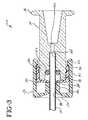
- an adapter 10 of the present invention useful for attaching a fluid handling device to a catheter 12includes a body 14 having a proximal end 16, a distal end 18 and an open passageway 20 therethrough.
- Passageway 20includes a seat 22 to receive catheter 12 and a cavity 24 distal to catheter seat 22.
- Adapter 10further includes a retainer 30, disposed on distal end 18 of body 14 over gasket 26 with an opening 32 therethrough that is substantially aligned with passageway 20. Opening 32 is sufficient to allow catheter 12 to pass through into passageway 20 to engage gasket 26 and catheter seat 22.
- Retainer 30has a plurality of flexible projections 34 into opening 32 that are sized and shaped to engage catheter 12 and be proximally deflected by the placement of catheter 12 on catheter seat 22.
- open port 38has a tapered entrance area 39 to ease placement of catheter 12 into passageway 20 through port 38.
- Collar 36has a plurality of proximal protuberances 40 disposed to engage flexible projections 34 and to prevent distal flexion of the flexible projections on retainer 30 when collar 36 is in a first position, best seen in Fig.
- protuberances 40are disposed not to engage flexible projections 34 when collar 36 is rotated to a second position, best seen in Figs. 4 and 5, with respect to body 14 thereby to allow a distal flexion of projections 34 and a withdrawal of catheter 12 from adapter 10.
- Proximal end 16preferably includes a female luer fitting 17 to facilitate attachment of a fluid handling device such as a syringe.
- Gasket 26is preferably formed from a resilient elastomeric material. Suitable elastomeric materials include, but are not limited to, natural rubber, silicone elastomer, ethylene propylene diene monomer (EPDM) and the like. Preferably, a material is selected with a Shore A durometer between about 45 and 70 formed into the shape of an "O" ring with an internal diameter and thickness suitable for forming a substantially fluid tight seal between the catheter and the adapter.
- retainer 30 with the plurality of projections 34may be formed from thermoplastic material or formed from a flexible metallic material, preferably with three or four projections 34.
- Projections 34have an attached end 42 and a free end 44 that preferably is shaped into a sharp wedge shape 46 to engage catheter 12 when it is positioned into adapter 10.
- Projections 34are sized and shaped so that they are flexed proximally and engage catheter 12 as the catheter is moved proximally to catheter seat 22, but do not penetrate the catheter wall or occlude the bore.
- Suitable materials for forming retainer 30include, but are not limited to, thermoplastic materials such as polystyrene, polycarbonate, polypropylene, polyamide, polyacrylate, polyacetal, polysulfone and the like.
- Suitable metallic materials for forming retainer 30include, but are not limited to, or any other flexible metallic material suitable for use in medical applications. When a metallic material is selected, retainer 30 may be formed by stamping, electromachining, edm or other metal working techniques suitable for forming thin flexible metal parts. Retainer 30 is preferably fixedly attached to body 14 by mechanical attachment including, but not limited to, the interaction of a projecting ring 47 and an annular groove 48 in retainer 30.
- Retainer 30also defines a shoulder 50 that is sized and disposed to be engaged by a lip 52 on collar 36 to retain the collar on the body and allow for rotation of the collar with respect to the body.
- collar 36has a number of proximal protuberances 40 disposed to engage a like number of projections 34 when collar 36 is in the first position with respect to body 14.
- Protuberances 40are disposed to so that when collar 36 is rotated to the second position with respect to body 14, protuberances 40 are do not engage projections 34 thereby allowing the projection to deflect proximally as catheter 12 is withdrawn distally from the adapter and release the catheter.
- collar 36is rotated about one-sixth of a revolution with respect to body 14 to release the catheter.
- Fig. 5awhere there are three projections 34
- projections 34 and protuberances 40are sized and shaped so that, once collar 36 is rotated from the first position to the second position with respect to body 14 thereby disengaging protuberances 40 from projections 34, projections 34 and protuberances 40 interfere with each other to substantially prevent rotation of the collar from the second position to the first position. This prevention of returning collar 36 to the first position, serves to substantially prevent adapter 10 from again being mounted onto a catheter and actively substantially prevents reuse of the adapter of the invention.
- Body 14is may formed from a thermoplastic material such as polystyrene, polypropylene, polycarbonate, polyamide, polyacrylate, polyacetal, polysulfone and the like.
- body 14is formed from a substantially transparent material so that when catheter 12 is positioned in passageway 20 on catheter seat 22, it is visible to the practitioner.
- adapter 10is placed in a package 15, illustrated in phantom in Fig. 1, formed from materials substantially resistant to microorganisms, sealed in the package and exposed to agents that substantially render any microorganisms inside non-viable.
- adapter 10has collar 36 in the first position with respect to body 14 when placed in package 15 so that the adapter is ready for use as soon as the package is opened.
- Suitable materials for forming package 15include, but are not limited to paper, non-wovens, thermoplastic films, metallic foils and composites of these materials.
- Suitable agents for rendering the microorganisms non-viableinclude, but are not limited to, ethylene oxide, ionizing radiation and the like.
- a method for mounting adapter 10 onto a catheter 12includes orienting catheter 12 with distal open port 38 and proximally advancing catheter 12 until the proximal end of the catheter is seated on catheter seat 22.
- Adapter 10is now ready for the practitioner to attach a suitable fluid handling device.
- FIGs. 6, 7 and 8an alternate embodiment to the adapter is shown that is similar to the cross-sectional views of the adapter illustrated in Figs. 3, 4, 5a and 5b.
- this embodimentthere are elements similar in structure and function to the embodiment of the present invention shown in Figs. 1-5b. Accordingly, substantially similar components that perform substantially similar functions are numbered identically to those components of the embodiment of Figs. 1-5b except that a suffix "a" is added to identify those components in Figs. 6, 7 and 8.
- an adapter 10a of the present invention useful for attaching a fluid handling device to a catheter 12aincludes a body 14a having a proximal end 16a, a distal end 18a and an open passageway 20a therethrough.
- Passageway 20aincludes a seat 22a to receive catheter 12a and a cavity 24a proximal to catheter seat 22a.
- Adapter 10afurther includes a retainer 30a, disposed on proximal end 16a of body 14a over gasket 26a with an opening 32a therethrough that is substantially aligned with passageway 20a.
- Opening 32ais sufficient to allow catheter 12a to pass through into passageway 20a to engage gasket 26a and catheter seat 22a.
- Retainer 30ahas a plurality of flexible projections 34a into opening 32a that are sized and shaped to engage catheter 12a and be proximally deflected by the placement of catheter 12a on catheter seat 22a.
- open port 38ahas a tapered entrance area 39a to ease placement of catheter 12a into passageway 20a through port 38a.
- Collar 36ahas a proximal protuberance 40a, in this embodiment preferably in the form of a cylinder, disposed to engage flexible projections 34a, best seen in Fig. 8, and to prevent distal flexion of the flexible projections on retainer 30a when collar 36a is in a first position, best seen in Fig. 6, with respect to body 14a thus to retaining catheter 12a in adapter 10a for attachment to a fluid handling device. Additionally, protuberance 40a is disposed not to engage flexible projections 34a by distally withdrawing collar 36a away from retainer 30a as collar 36a rotated to a second position, best seen in Fig. 7, thereby to allow a distal flexion of projections 34a and a withdrawal of catheter 12 from adapter 10.
- protuberance 40ais disposed not to engage flexible projections 34a by distally withdrawing collar 36a away from retainer 30a as collar 36a rotated to a second position, best seen in Fig. 7, thereby to allow a distal flexion of projections 34
- collar 36aincludes a female thread 60 and retainer 30a includes a male thread 62.
- threads 60 and 62include a stop 64 to prevent collar 36a from being rotated more than an amount sufficient to substantially eliminate contact between distal protuberance 40a and projections 34a.
- Stop 64preferably is sized and shaped so that a force for rotation between the first position and the second position is substantially less than a force for rotation between the second position and the first position, thereby substantially preventing inadvertent reuse of the adapter.
- the inventionprovides practitioners with an easy-to-use adapter for attaching a fluid handling device to a catheter.
- the adapter of the inventiondoes not require as much manipulation to mount as previous adapters, is readily and intuitively dismounted and, substantially prevents inadvertent reuse
Landscapes
- Health & Medical Sciences (AREA)
- Heart & Thoracic Surgery (AREA)
- Pulmonology (AREA)
- Engineering & Computer Science (AREA)
- Anesthesiology (AREA)
- Biomedical Technology (AREA)
- Hematology (AREA)
- Life Sciences & Earth Sciences (AREA)
- Animal Behavior & Ethology (AREA)
- General Health & Medical Sciences (AREA)
- Public Health (AREA)
- Veterinary Medicine (AREA)
- Infusion, Injection, And Reservoir Apparatuses (AREA)
- Media Introduction/Drainage Providing Device (AREA)
Abstract
Description
Claims (10)
- An adapter for attaching a fluid handling device to a catheter comprising:a body having a proximal end, a distal end and an open passageway therethrough,said passageway including a seat to receive the catheter and a cavity distal to saidcatheter seat;a gasket disposed in said cavity to form a substantially fluid tight seal about thecatheter when the catheter is positioned on said catheter seat;a retainer, disposed on the distal end of the body over said gasket, said retainerhaving an opening therethrough substantially aligned with said passageway sufficient toallow the catheter to pass through into said passageway to engage said gasket and saidcatheter seat, said retainer having a plurality of flexible projections into said openingbeing sized and shaped to engage the catheter and be proximally deflected by theplacement of the catheter on said catheter seat; anda rotatable collar disposed over said retainer on said distal end of said body, saidcollar having an open port therethrough substantially aligned with said passageway toallow placement of the catheter into said passageway, said collar having a plurality ofproximal protuberances disposed to engage said flexible projections and to prevent distalflexion of said flexible projections on said retainer when said collar is in a first positionwith respect to said body thereby to retain the catheter in said adapter for attachment to afluid handling device, whereby said protuberances being disposed not to engage saidflexible projections when said collar is rotated to a second position with respect to saidbody thereby to allow a distal flexion of said projections and a withdrawal of the catheterfrom said adapter.
- The adapter of claim 1 wherein said proximal end of said body furtherincludes a female luer fitting to attach said adapter to the fluid handling device.
- The adapter of claim 1 wherein said gasket is formed from a resilientelastomeric material.
- The adapter of claim 3 wherein said resilient elastomeric material has adurometer between about Shore A 45 and 70 and is selected from the group consisting ofnatural rubber, silicone elastomer and ethylene propylene diene monomer (EPDM).
- The adapter of claim 4 wherein said resilient elastomeric material isshaped into the form of an "O" ring.
- The adapter of claim 1 wherein said retainer has four projectionssubstantially equally arranged about said opening.
- The adapter of claim 1 wherein said retainer has three projectionssubstantially equally arranged about said opening.
- The adapter of claim 1 wherein said projections on said retainer each havean attached end and a free end that projects into said opening in said retainer, said freeends each comprising a sharp wedge disposed to engage the catheter when the catheter isplaced into said passageway onto said catheter seat, so that a force for insertion of thecatheter into the passageway and onto said catheter seat is less than a force forwithdrawal of the catheter from the passageway when said collar is in said first position.
- The adapter of claim 1 wherein said body and said collar are each formedfrom a thermoplastic material selected from the group consisting of polystyrene,polypropylene, polycarbonate, polyamide, polyacrylate, polyacetal and polysulfone.
- The adapter of claim 9 wherein said body is formed from a substantiallytransparent material so that a practitioner can observe proper placement of the catheter onsaid catheter seat.
Applications Claiming Priority (2)
| Application Number | Priority Date | Filing Date | Title |
|---|---|---|---|
| US32157 | 1998-02-27 | ||
| US09/032,157US5989240A (en) | 1998-02-27 | 1998-02-27 | Adaptor for mounting a fluid handling device on a catheter tubing |
Publications (3)
| Publication Number | Publication Date |
|---|---|
| EP0941743A2true EP0941743A2 (en) | 1999-09-15 |
| EP0941743A3 EP0941743A3 (en) | 1999-10-20 |
| EP0941743B1 EP0941743B1 (en) | 2003-08-06 |
Family
ID=21863415
Family Applications (1)
| Application Number | Title | Priority Date | Filing Date |
|---|---|---|---|
| EP99103732AExpired - LifetimeEP0941743B1 (en) | 1998-02-27 | 1999-02-25 | Adapter for mounting a fluid handling device on a catheter tubing |
Country Status (7)
| Country | Link |
|---|---|
| US (1) | US5989240A (en) |
| EP (1) | EP0941743B1 (en) |
| JP (1) | JP4354564B2 (en) |
| AU (1) | AU747826B2 (en) |
| CA (1) | CA2263054C (en) |
| DE (1) | DE69910096T2 (en) |
| ES (1) | ES2200421T3 (en) |
Cited By (15)
| Publication number | Priority date | Publication date | Assignee | Title |
|---|---|---|---|---|
| EP1181946A1 (en)* | 2000-08-04 | 2002-02-27 | Alan David Mogg | Catheter adapter |
| EP1552858A1 (en)* | 2004-01-07 | 2005-07-13 | Nipro Corporation | Female connector |
| WO2012049532A1 (en) | 2010-12-16 | 2012-04-19 | Becton Dickinson France | Adaptor and drug delivery device |
| WO2015179180A1 (en)* | 2014-05-20 | 2015-11-26 | Avent, Inc. | Catheter connector insert |
| CN111065311A (en)* | 2017-07-20 | 2020-04-24 | 海王星医疗公司 | Dynamic rigidized outer casing |
| US11478608B2 (en) | 2018-07-19 | 2022-10-25 | Neptune Medical Inc. | Dynamically rigidizing composite medical structures |
| US11744443B2 (en) | 2020-03-30 | 2023-09-05 | Neptune Medical Inc. | Layered walls for rigidizing devices |
| US11793392B2 (en) | 2019-04-17 | 2023-10-24 | Neptune Medical Inc. | External working channels |
| US11937778B2 (en) | 2022-04-27 | 2024-03-26 | Neptune Medical Inc. | Apparatuses and methods for determining if an endoscope is contaminated |
| US11944277B2 (en) | 2016-08-18 | 2024-04-02 | Neptune Medical Inc. | Device and method for enhanced visualization of the small intestine |
| US12059128B2 (en) | 2018-05-31 | 2024-08-13 | Neptune Medical Inc. | Device and method for enhanced visualization of the small intestine |
| US12082776B2 (en) | 2015-09-03 | 2024-09-10 | Neptune Medical Inc. | Methods for advancing a device through a gastrointestinal tract |
| US12121677B2 (en) | 2021-01-29 | 2024-10-22 | Neptune Medical Inc. | Devices and methods to prevent inadvertent motion of dynamically rigidizing apparatuses |
| US12329473B2 (en) | 2019-04-17 | 2025-06-17 | Neptune Medical Inc. | Dynamically rigidizing composite medical structures |
| US12330292B2 (en) | 2023-09-28 | 2025-06-17 | Neptune Medical Inc. | Telescoping robot |
Families Citing this family (40)
| Publication number | Priority date | Publication date | Assignee | Title |
|---|---|---|---|---|
| EP1716885A3 (en)* | 1997-05-09 | 2006-11-15 | Pall Corporation | Connector assemblies, fluid systems, and methods for making a connection |
| DK0983463T3 (en)* | 1997-05-30 | 2002-12-16 | Oystertec Plc | Connector for tubular components connection |
| US6155607A (en)* | 1998-02-17 | 2000-12-05 | Parker-Hannifin Corporation | Quick connect coupling |
| US6511472B1 (en) | 1999-05-21 | 2003-01-28 | Microtherapeutics, Inc. | Interface needle and method for creating a blunt interface between delivered liquids |
| US6367665B1 (en)* | 2000-11-13 | 2002-04-09 | Saint-Gobain Calmar Inc. | Trigger sprayer dispensing system |
| IL157561A0 (en) | 2001-03-04 | 2004-03-28 | Sterling Medivations Inc | Infusion hub assembly and fluid line disconnect system |
| US6679529B2 (en)* | 2001-08-06 | 2004-01-20 | Theodore D. Johnson | Connection system |
| US6955663B2 (en)* | 2002-04-19 | 2005-10-18 | Keun-Ho Lee | Catheter for extracting and inserting humors |
| US7044936B2 (en) | 2002-08-21 | 2006-05-16 | Arrow International Inc. | Catheter connector with pivot lever spring latch |
| US6969381B2 (en)* | 2002-12-18 | 2005-11-29 | Medical Components, Inc. | Multi-lumen catheter with detachable locking hub |
| US20090160178A1 (en)* | 2003-05-29 | 2009-06-25 | Ericksen Kent C | Centering system for coupling for irrigation system |
| US20090160179A1 (en)* | 2003-05-29 | 2009-06-25 | Ericksen Kent C | Coupling release mechanism for irrigation system |
| US7021672B2 (en)* | 2003-05-29 | 2006-04-04 | Orbit Irrigation Products, Inc. | Irrigation coupling apparatus and method |
| US9429262B2 (en) | 2003-05-29 | 2016-08-30 | Orbit Irrigation Products, Inc. | Conduit coupling apparatus and method |
| FR2856912B1 (en)* | 2003-07-04 | 2008-05-23 | Tokendo | REMOVABLE OPERATING DEVICE FOR MEDICALALLY VENTABLE ENDOSCOPIC PROBE |
| US8608727B2 (en)* | 2004-03-01 | 2013-12-17 | Smiths Medical Asd, Inc. | Delivery system and method |
| US7497484B2 (en)* | 2004-08-11 | 2009-03-03 | Smiths Medical Asd, Inc. | Medical coupling system |
| US20060157972A1 (en)* | 2005-01-03 | 2006-07-20 | Douglas Catton | Inside reducing pipe bushing |
| US20070016166A1 (en)* | 2005-07-08 | 2007-01-18 | Thistle Robert C | Catheter attachment collet for a central port |
| US8257286B2 (en)* | 2006-09-21 | 2012-09-04 | Tyco Healthcare Group Lp | Safety connector apparatus |
| KR100899654B1 (en) | 2007-07-12 | 2009-05-27 | 주식회사 메디라바텍 | Spinal needles for drug injection |
| US20090112187A1 (en)* | 2007-10-25 | 2009-04-30 | Cook Vascuiar Incorporated | Catheter retention mechanism |
| US8257287B2 (en) | 2008-03-20 | 2012-09-04 | Tyco Healthcare Group Lp | Safety connector assembly |
| US9138207B2 (en) | 2009-05-19 | 2015-09-22 | Teleflex Medical Incorporated | Methods and devices for laparoscopic surgery |
| EP3251604B1 (en) | 2010-01-20 | 2020-04-22 | EON Surgical Ltd. | System of deploying an elongate unit in a body cavity |
| US8721539B2 (en) | 2010-01-20 | 2014-05-13 | EON Surgical Ltd. | Rapid laparoscopy exchange system and method of use thereof |
| US9364651B2 (en) | 2010-02-23 | 2016-06-14 | Smiths Medical Asd, Inc. | Adapter with special fitting |
| US8454059B2 (en) | 2010-09-13 | 2013-06-04 | Pall Corporation | Connector assemblies, fluid systems including connector assemblies, and procedures for making fluid connections |
| EP2615980B1 (en) | 2010-09-19 | 2017-08-16 | EON Surgical Ltd. | Micro laparoscopy devices and deployments thereof |
| US11384872B1 (en) | 2011-05-24 | 2022-07-12 | Husqvarna Ab | Conduit coupling apparatus and method |
| WO2012162554A1 (en) | 2011-05-24 | 2012-11-29 | Orbit Irrigation Products, Inc. | Conduit coupling apparatus and method |
| US9220833B2 (en) | 2011-06-27 | 2015-12-29 | Smiths Medical Asd, Inc. | Medicament infusion systems |
| US8870238B2 (en) | 2011-06-27 | 2014-10-28 | Smiths Medical Asd, Inc. | Fitting for medicament infusion systems |
| US10743932B2 (en) | 2011-07-28 | 2020-08-18 | Biosense Webster (Israel) Ltd. | Integrated ablation system using catheter with multiple irrigation lumens |
| US8808273B2 (en) | 2012-02-10 | 2014-08-19 | Biosense Webster (Israel) Ltd. | Electrophysiology catheter with mechanical use limiter |
| US9155866B2 (en)* | 2012-09-13 | 2015-10-13 | Becton, Dickinson And Company | Luer securement device |
| USD732359S1 (en) | 2012-08-21 | 2015-06-23 | Orbit Irrigation Products, Inc. | Conduit removal tool |
| JP6492059B2 (en) | 2013-05-01 | 2019-03-27 | バイエル・ヘルスケア・エルエルシーBayer HealthCare LLC | Fluid path set bolus control device |
| US9227047B2 (en)* | 2013-10-29 | 2016-01-05 | Avent, Inc. | Catheter connector |
| WO2024197367A1 (en)* | 2023-03-30 | 2024-10-03 | Janotti Cavalcante Ricardo | Syringe for catheterisation procedures |
Citations (2)
| Publication number | Priority date | Publication date | Assignee | Title |
|---|---|---|---|---|
| US5053015A (en) | 1989-08-30 | 1991-10-01 | The Kendall Company | Locking catheter adapter |
| US5226898A (en) | 1989-08-30 | 1993-07-13 | The Kendall Company | Catheter adapter with strain relief |
Family Cites Families (23)
| Publication number | Priority date | Publication date | Assignee | Title |
|---|---|---|---|---|
| US4013310A (en)* | 1975-07-09 | 1977-03-22 | The Kendall Company | Tubing connector |
| US4323065A (en)* | 1980-01-17 | 1982-04-06 | Baxter Travenol Laboratories, Inc. | Attachable connector for catheter |
| US4676530A (en)* | 1983-04-07 | 1987-06-30 | Warner-Lambert Company | Coupling assembly for use in fluid flow systems |
| IT8583626A0 (en)* | 1985-11-25 | 1985-11-25 | Vulcano Di Pozzi Gian Carlo | "UNISEX" SELF-LOCKING FITTING WITH "CLIK" FOR QUICK CONNECTION OF PLASTIC HOSES. |
| DE3624745A1 (en)* | 1986-07-22 | 1988-02-04 | Sterimed Gmbh | Coupling for connection of a medical tube, especially a drain or a catheter, to another device |
| US4842592A (en)* | 1987-05-06 | 1989-06-27 | Teleflex Incorporated | Connector assembly |
| US5129891A (en)* | 1989-05-19 | 1992-07-14 | Strato Medical Corporation | Catheter attachment device |
| DE3920130A1 (en)* | 1989-06-20 | 1991-01-10 | Henkel Kgaa | USE OF PARTIAL ESTERS OF OLIGOGLYCERINES WITH FATTY ACIDS AS PIGMENT DISPERSATORS FOR AQUEOUS VARNISH DISPERSIONS |
| DE4100837A1 (en)* | 1991-01-14 | 1992-07-16 | Volker Bertram | ADAPTER WITH TRACHEAL TUBE |
| US5338314A (en)* | 1991-04-22 | 1994-08-16 | B. Braun Medical, Inc. | Rotating Y-connector |
| US5209740A (en)* | 1991-11-22 | 1993-05-11 | Abbott Laboratories | Catheter adapter having retention notches |
| US5279597A (en)* | 1992-01-13 | 1994-01-18 | Arrow International Investment Corp. | Catheter compression clamp |
| US5366262A (en)* | 1992-07-23 | 1994-11-22 | Furnas Electric Co. | Quick connect fluid fitting |
| US5405340A (en)* | 1992-10-07 | 1995-04-11 | Abbott Laboratories | Threaded securing apparatus for flow connectors |
| JP3247918B2 (en)* | 1993-06-18 | 2002-01-21 | 株式会社共和 | Medical bandage and its application method |
| US5312375A (en)* | 1993-06-28 | 1994-05-17 | Simon Gurmarnik | Set for spinal anesthesia |
| GB9325936D0 (en)* | 1993-12-18 | 1994-02-23 | Smiths Ind Public Ltd | Connectors |
| US5507732A (en)* | 1994-10-05 | 1996-04-16 | Medtronic, Inc. | Quick assembly catheter manifold |
| US5599328A (en)* | 1995-07-14 | 1997-02-04 | Merit Medical Systems, Inc. | Split ring assembly for an airless rotatable connector |
| US5695224A (en)* | 1995-08-14 | 1997-12-09 | The Rovac Corporation | Pipe joint assembly |
| US5584820A (en)* | 1995-08-25 | 1996-12-17 | Gurmarnik; Simon | Set for spinal anesthesia |
| US5730476A (en)* | 1995-10-11 | 1998-03-24 | Gouda; Osamu | Conduit coupling |
| US5993437A (en)* | 1998-01-15 | 1999-11-30 | Epimed International, Inc. | Catheter connector |
- 1998
- 1998-02-27USUS09/032,157patent/US5989240A/ennot_activeExpired - Lifetime
- 1999
- 1999-02-25DEDE69910096Tpatent/DE69910096T2/ennot_activeExpired - Lifetime
- 1999-02-25ESES99103732Tpatent/ES2200421T3/ennot_activeExpired - Lifetime
- 1999-02-25EPEP99103732Apatent/EP0941743B1/ennot_activeExpired - Lifetime
- 1999-02-26CACA002263054Apatent/CA2263054C/ennot_activeExpired - Lifetime
- 1999-02-26AUAU18475/99Apatent/AU747826B2/ennot_activeExpired
- 1999-03-01JPJP05334899Apatent/JP4354564B2/ennot_activeExpired - Lifetime
Patent Citations (2)
| Publication number | Priority date | Publication date | Assignee | Title |
|---|---|---|---|---|
| US5053015A (en) | 1989-08-30 | 1991-10-01 | The Kendall Company | Locking catheter adapter |
| US5226898A (en) | 1989-08-30 | 1993-07-13 | The Kendall Company | Catheter adapter with strain relief |
Cited By (31)
| Publication number | Priority date | Publication date | Assignee | Title |
|---|---|---|---|---|
| EP1181946A1 (en)* | 2000-08-04 | 2002-02-27 | Alan David Mogg | Catheter adapter |
| US6676652B2 (en) | 2000-08-04 | 2004-01-13 | Alan David Mogg | Catheter adapter |
| EP1552858A1 (en)* | 2004-01-07 | 2005-07-13 | Nipro Corporation | Female connector |
| US7128348B2 (en) | 2004-01-07 | 2006-10-31 | Nipro Corporation | Female connector |
| US10391248B2 (en) | 2010-12-16 | 2019-08-27 | Becton Dickinson France | Adaptor and drug delivery device |
| US9717855B2 (en) | 2010-12-16 | 2017-08-01 | Becton Dickinson France | Adaptor and drug delivery device |
| US12434000B2 (en) | 2010-12-16 | 2025-10-07 | Becton Dickinson France | Adaptor and drug delivery device |
| US11383039B2 (en) | 2010-12-16 | 2022-07-12 | Becton Dickinson France | Adaptor and drug delivery device |
| WO2012049532A1 (en) | 2010-12-16 | 2012-04-19 | Becton Dickinson France | Adaptor and drug delivery device |
| WO2015179180A1 (en)* | 2014-05-20 | 2015-11-26 | Avent, Inc. | Catheter connector insert |
| AU2015264564B2 (en)* | 2014-05-20 | 2019-07-11 | Avent, Inc. | Catheter connector insert |
| US12082776B2 (en) | 2015-09-03 | 2024-09-10 | Neptune Medical Inc. | Methods for advancing a device through a gastrointestinal tract |
| US12336695B2 (en) | 2016-08-18 | 2025-06-24 | Neptune Medical Inc. | Device and method for enhanced visualization of the small intestine |
| US11944277B2 (en) | 2016-08-18 | 2024-04-02 | Neptune Medical Inc. | Device and method for enhanced visualization of the small intestine |
| CN111065311A (en)* | 2017-07-20 | 2020-04-24 | 海王星医疗公司 | Dynamic rigidized outer casing |
| US12295550B2 (en) | 2017-07-20 | 2025-05-13 | Neptune Medical Inc. | Dynamically rigidizing overtube |
| US12059128B2 (en) | 2018-05-31 | 2024-08-13 | Neptune Medical Inc. | Device and method for enhanced visualization of the small intestine |
| US12311122B2 (en) | 2018-07-19 | 2025-05-27 | Neptune Medical Inc. | Rigidizing overtube with hemostasis valve |
| US11724065B2 (en) | 2018-07-19 | 2023-08-15 | Neptune Medical Inc. | Nested rigidizing devices |
| US11554248B1 (en) | 2018-07-19 | 2023-01-17 | Neptune Medical Inc. | Rigidizing devices |
| US12285571B2 (en) | 2018-07-19 | 2025-04-29 | Neptune Medical Inc. | Methods of performing vascular procedures using a rigidizing device |
| US11478608B2 (en) | 2018-07-19 | 2022-10-25 | Neptune Medical Inc. | Dynamically rigidizing composite medical structures |
| US11793392B2 (en) | 2019-04-17 | 2023-10-24 | Neptune Medical Inc. | External working channels |
| US12329473B2 (en) | 2019-04-17 | 2025-06-17 | Neptune Medical Inc. | Dynamically rigidizing composite medical structures |
| US12193637B2 (en) | 2019-04-17 | 2025-01-14 | Neptune Medical Inc. | External working channels |
| US11744443B2 (en) | 2020-03-30 | 2023-09-05 | Neptune Medical Inc. | Layered walls for rigidizing devices |
| US12121677B2 (en) | 2021-01-29 | 2024-10-22 | Neptune Medical Inc. | Devices and methods to prevent inadvertent motion of dynamically rigidizing apparatuses |
| US12324565B2 (en) | 2022-04-27 | 2025-06-10 | Neptune Medical Inc. | Methods of attaching a rigidizing sheath to an endoscope |
| US12102289B2 (en) | 2022-04-27 | 2024-10-01 | Neptune Medical Inc. | Methods of attaching a rigidizing sheath to an endoscope |
| US11937778B2 (en) | 2022-04-27 | 2024-03-26 | Neptune Medical Inc. | Apparatuses and methods for determining if an endoscope is contaminated |
| US12330292B2 (en) | 2023-09-28 | 2025-06-17 | Neptune Medical Inc. | Telescoping robot |
Also Published As
| Publication number | Publication date |
|---|---|
| AU1847599A (en) | 1999-09-09 |
| EP0941743B1 (en) | 2003-08-06 |
| DE69910096T2 (en) | 2004-06-17 |
| US5989240A (en) | 1999-11-23 |
| EP0941743A3 (en) | 1999-10-20 |
| CA2263054C (en) | 2002-12-10 |
| ES2200421T3 (en) | 2004-03-01 |
| CA2263054A1 (en) | 1999-08-27 |
| JPH11319114A (en) | 1999-11-24 |
| AU747826B2 (en) | 2002-05-23 |
| DE69910096D1 (en) | 2003-09-11 |
| JP4354564B2 (en) | 2009-10-28 |
Similar Documents
| Publication | Publication Date | Title |
|---|---|---|
| EP0941743B1 (en) | Adapter for mounting a fluid handling device on a catheter tubing | |
| US5992899A (en) | Adapter for mounting a fluid handling device on a catheter tubing | |
| JP2788263B2 (en) | Catheter assembly | |
| CA2503678C (en) | Automatic valve | |
| US5833674A (en) | Needleless IV medical delivery system | |
| US5139483A (en) | Medical intravenous administration line connector | |
| EP0874656B1 (en) | Coupling system for safety cannula | |
| EP1460993B1 (en) | Low profile adaptor for use with a medical catheter | |
| US9539419B2 (en) | Male connector and transfusion line connection apparatus equipped with male connector | |
| US11724044B2 (en) | Flow control plug securement | |
| EP1790376A1 (en) | Single lumen adapter for automatic valve | |
| IE62767B1 (en) | Pre-slit injection site and tapered cannula | |
| EP0856332A1 (en) | Adapter for mounting a fluid handling device on a catheter tubing | |
| AU645096B2 (en) | Medical intravenous administration line connector | |
| WO1995005863A1 (en) | Needleless iv medical delivery system | |
| US20230310801A1 (en) | Closed system catheter | |
| MXPA98000785A (en) | Adapter to install, in a catheter pipe, a device for the handling of flui | |
| AU683226B2 (en) | Needleless IV medical delivery system | |
| CA2158744C (en) | Securing collar for cannula connector |
Legal Events
| Date | Code | Title | Description |
|---|---|---|---|
| PUAI | Public reference made under article 153(3) epc to a published international application that has entered the european phase | Free format text:ORIGINAL CODE: 0009012 | |
| PUAL | Search report despatched | Free format text:ORIGINAL CODE: 0009013 | |
| AK | Designated contracting states | Kind code of ref document:A2 Designated state(s):DE ES FR GB IT | |
| AX | Request for extension of the european patent | Free format text:AL;LT;LV;MK;RO;SI | |
| AK | Designated contracting states | Kind code of ref document:A3 Designated state(s):AT BE CH CY DE DK ES FI FR GB GR IE IT LI LU MC NL PT SE | |
| AX | Request for extension of the european patent | Free format text:AL;LT;LV;MK;RO;SI | |
| 17P | Request for examination filed | Effective date:20000405 | |
| AKX | Designation fees paid | Free format text:DE ES FR GB IT | |
| GRAH | Despatch of communication of intention to grant a patent | Free format text:ORIGINAL CODE: EPIDOS IGRA | |
| GRAH | Despatch of communication of intention to grant a patent | Free format text:ORIGINAL CODE: EPIDOS IGRA | |
| GRAA | (expected) grant | Free format text:ORIGINAL CODE: 0009210 | |
| AK | Designated contracting states | Designated state(s):DE ES FR GB IT | |
| REG | Reference to a national code | Ref country code:GB Ref legal event code:FG4D | |
| REF | Corresponds to: | Ref document number:69910096 Country of ref document:DE Date of ref document:20030911 Kind code of ref document:P | |
| REG | Reference to a national code | Ref country code:ES Ref legal event code:FG2A Ref document number:2200421 Country of ref document:ES Kind code of ref document:T3 | |
| ET | Fr: translation filed | ||
| PLBE | No opposition filed within time limit | Free format text:ORIGINAL CODE: 0009261 | |
| STAA | Information on the status of an ep patent application or granted ep patent | Free format text:STATUS: NO OPPOSITION FILED WITHIN TIME LIMIT | |
| 26N | No opposition filed | Effective date:20040507 | |
| REG | Reference to a national code | Ref country code:FR Ref legal event code:PLFP Year of fee payment:18 | |
| REG | Reference to a national code | Ref country code:FR Ref legal event code:PLFP Year of fee payment:19 | |
| REG | Reference to a national code | Ref country code:FR Ref legal event code:PLFP Year of fee payment:20 | |
| PGFP | Annual fee paid to national office [announced via postgrant information from national office to epo] | Ref country code:GB Payment date:20180122 Year of fee payment:20 Ref country code:ES Payment date:20180301 Year of fee payment:20 Ref country code:DE Payment date:20180122 Year of fee payment:20 | |
| PGFP | Annual fee paid to national office [announced via postgrant information from national office to epo] | Ref country code:IT Payment date:20180122 Year of fee payment:20 Ref country code:FR Payment date:20180123 Year of fee payment:20 | |
| REG | Reference to a national code | Ref country code:DE Ref legal event code:R071 Ref document number:69910096 Country of ref document:DE | |
| REG | Reference to a national code | Ref country code:GB Ref legal event code:PE20 Expiry date:20190224 | |
| PG25 | Lapsed in a contracting state [announced via postgrant information from national office to epo] | Ref country code:GB Free format text:LAPSE BECAUSE OF EXPIRATION OF PROTECTION Effective date:20190224 | |
| REG | Reference to a national code | Ref country code:ES Ref legal event code:FD2A Effective date:20200904 | |
| PG25 | Lapsed in a contracting state [announced via postgrant information from national office to epo] | Ref country code:ES Free format text:LAPSE BECAUSE OF EXPIRATION OF PROTECTION Effective date:20190226 |