EP0938958B1 - Cutting segment - Google Patents
Cutting segmentDownload PDFInfo
- Publication number
- EP0938958B1 EP0938958B1EP19980870041EP98870041AEP0938958B1EP 0938958 B1EP0938958 B1EP 0938958B1EP 19980870041EP19980870041EP 19980870041EP 98870041 AEP98870041 AEP 98870041AEP 0938958 B1EP0938958 B1EP 0938958B1
- Authority
- EP
- European Patent Office
- Prior art keywords
- segment
- cutting
- segments
- protrusions
- saw
- Prior art date
- Legal status (The legal status is an assumption and is not a legal conclusion. Google has not performed a legal analysis and makes no representation as to the accuracy of the status listed.)
- Expired - Lifetime
Links
- 238000005520cutting processMethods0.000titleclaimsdescription48
- 238000004519manufacturing processMethods0.000claimsdescription7
- 238000003754machiningMethods0.000claimsdescription6
- 239000004575stoneSubstances0.000claims2
- 230000003247decreasing effectEffects0.000claims1
- 230000007704transitionEffects0.000description15
- 239000000463materialSubstances0.000description14
- 239000000843powderSubstances0.000description4
- 239000003082abrasive agentSubstances0.000description3
- 229910003460diamondInorganic materials0.000description3
- 239000010432diamondSubstances0.000description3
- 230000000694effectsEffects0.000description3
- 238000000034methodMethods0.000description3
- 230000008901benefitEffects0.000description2
- 239000011230binding agentSubstances0.000description2
- 239000002826coolantSubstances0.000description2
- 230000007423decreaseEffects0.000description2
- 239000000203mixtureSubstances0.000description2
- 238000003825pressingMethods0.000description2
- 238000005245sinteringMethods0.000description2
- 101100008047Caenorhabditis elegans cut-3 geneProteins0.000description1
- 235000009508confectioneryNutrition0.000description1
- 238000001816coolingMethods0.000description1
- 230000007547defectEffects0.000description1
- 230000001788irregularEffects0.000description1
- 238000005259measurementMethods0.000description1
- 238000002360preparation methodMethods0.000description1
- 230000000750progressive effectEffects0.000description1
- 238000000926separation methodMethods0.000description1
- 239000010802sludgeSubstances0.000description1
- 238000005476solderingMethods0.000description1
Images


Classifications
- B—PERFORMING OPERATIONS; TRANSPORTING
- B28—WORKING CEMENT, CLAY, OR STONE
- B28D—WORKING STONE OR STONE-LIKE MATERIALS
- B28D1/00—Working stone or stone-like materials, e.g. brick, concrete or glass, not provided for elsewhere; Machines, devices, tools therefor
- B28D1/02—Working stone or stone-like materials, e.g. brick, concrete or glass, not provided for elsewhere; Machines, devices, tools therefor by sawing
- B28D1/12—Saw-blades or saw-discs specially adapted for working stone
- B28D1/121—Circular saw blades
Definitions
- the present inventionrelates to cutting segments for circular saw or armor saw, these segments having a particular geometry of the general type known from FR-A-2 399 904. Segments of cut can be obtained by sintering a mixture of powders of a binder, and of an abrasive material such as diamond. Tools with these segments can be used for sawing hard materials, such as Pierre.
- the inventionalso relates to a method of realization of the punches necessary for the confection of these segments.
- the saw cutting segmentshave general in essence the shape of a parallelepiped rectangle of height X, width l and length L.
- the form and operating principle of such segmentsare illustrated in figure 1. It is in the codification of the European Federation of Abrasive Producers that the height of a cutting segment is called "X".
- Each cutting segmentis mounted on the cutting blade saw through his foot.
- the bladepenetrates a material to be sawn, it does it by its face called “cutting face”, which cuts the material and determines the saw line, which increases as and when measurement of the sawing operation, while the segments sink into their height in the saw cut.
- the segmentswear out, which amounts to saying that their height X (between the cutting face and the foot of the segment) decreases.
- Cutting segmentsare most often produced by sintering a powder of a binder, with a powder of a abrasive material such as diamond.
- the powder mixtureis introduced into a mold, then compressed with a punch.
- This punchmust be made of a material capable of resist the significant pressures implemented for the production of cutting segments, and must be able to resist to wear in the presence of an abrasive material. He must therefore be made of a hard material, and therefore difficult to machined.
- the cutting segments described in JP 01 109 079 A and WO 95/22446have relatively shaped shapes complex, and the punches necessary for their production are therefore difficult to achieve.
- the object of the present inventionis precisely to provide a cutting tool segment that does not have the disadvantages mentioned above. Its purpose is to provide stepped cutting segments that allow for quick and easy transition between two successive stages.
- a cutting segment for circular or armor sawsubstantially shaped of rectangular parallelepiped, having a height greater than 5 mm, and comprising several stages.
- the segment widthdecreases in successive steps from cutting face of the segment at its base.
- the landing between a floor and the next lower floor, width reduced,is a bearing parallel to the cutting face of the segment, extended by one or more protrusions of a width equal to the width of the upper floor, spanning a portion of the length and height from the lower floor.
- the protrusionsare advantageously in number one or two per floor.
- these protrusionshave the shape of a half-disc whose diameter is between an eighth and a third of the segment length and is preferably equal to a quarter of the length of the segment.
- these protrusionshave the shape of a triangle.
- the inventionalso relates to a saw circular saw or armor saw on which are mounted cutting segments as described previously.
- the inventionalso relates to a method of production of punches for the manufacture of segments of section as previously described, in which the successive bearings are obtained by a first machining plan, and the circular protrusions are obtained at by means of a second circular machining.
- Figure 1is a schematic sectional view of a part of a saw with diamond segments following the prior art during work in a hard material.
- Figure 2is a view similar to that of Figure 1, the segment being eccentric in the saw cut.
- Figure 3is a sectional view of another saw according to the prior art, provided with stepped segments, the successive stages being separated by a landing parallel to the cutting face.
- Figure 4is a perspective view of a segment according to the prior art, the stages being separated by a bearing inclined with respect to the face of chopped off.
- Figure 5is a sectional view of a saw circular according to the prior art, provided with segments stages, the stages being separated by a landing inclined by compared to the cutting face.
- Figure 6is a side view of a stepped segment according to the prior art, the stages being separated by a inclined bearing with respect to the cutting face.
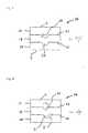
- Figure 7is a side view of a first embodiment of a segment according to the invention.
- Figure 8is a side view of a second form execution of a segment according to the invention.
- Figure 9is a perspective view of a third embodiment of a following segment the invention.
- Figures 10 and 11illustrate the calculation of the contact surface of the segments with the faces of the line saw.
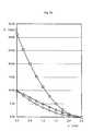
- Figure 12is a graph showing this area contact, depending on the height x remaining at consume, for various forms of following segments the invention and according to the prior art.
- Figure 1shows part of a saw blade 1 circular or armor blade according to the prior art, of which a segment 2, 8, 12, 16 is engaged in a line of saw 3.
- the cutting segment 2, 8, 12, 16is shaped substantially parallelepiped.
- the actual sawingis achieved by pressing the cutting face 4 of segment 2 on the bottom of the saw line 3.
- Abundant wateringcools saw 1 and the material to be cut and take away the mud and sawdust.
- Segments 2, 8, 12, 16 of saw 1are evenly distributed along of the saw blade and are joined by their foot 5 by an appropriate method, usually soldering.
- Figure 3is a sectional view of a saw 1 circular according to the prior art, provided with segments stages 8, the stages of each segment being separated by a bearing parallel to the cutting face.
- Segment 8 shown at the top of Figure 3has a fraction of a wide stage 9 which is not yet completely worn out, and a narrow floor 10 not started. In the segment shown in bottom of the figure, the wide stage 9 is completely worn out, and the narrow stage 10 is being worn.
- This saw circularis rotated around an axis 13. As this is set out above, in this embodiment of the prior art, the transition period between two floors 9 and 10 is particularly difficult.
- Figure 4shows a type of stepped segment 12 according to the prior art, the stages being separated by a bearing 11 inclined relative to the cutting face 4. This embodiment aims to improve the conditions of operation of saw 1 during the transition between two floors.
- Figure 5shows a circular saw 1 fitted with such segments 12, in which there is shown by the letter E the height of the segment portion extending to both on a wide floor 9 and on a narrow floor 10, hereinafter called the transition zone.
- the transition zonewe have represented the situation where the segment represented at the top of the figure begins the wear of the transition zone between a stage upper 9 of width L2 and a lower stage 10 of width L1, and the segment shown at the bottom of the figure has just finished the wear of this transition zone.
- This situationcan arise for example when the axis of rotation 13 of the saw 1 is offset by a runout E / 2 with respect to the axis of symmetry 14 of saw 1.
- Figure 6is a side view of the stepped segment according to prior art 12, shown above in the Figure 5, the floors being separated by an inclined landing with respect to the cutting face.
- a bearing 11 parallel to the face of section 4 of segment 16separates each of the stages 17, 18 from immediately lower floors 18, 19.
- Each floor upper 17, 18includes one or more protrusions 20, 21 extending the plan of the upper floor towards the low.
- These protuberancescan take any form suitable, for example a half-disc 20 (FIG. 7) or a triangle 21 (figure 8).
- the number of floorscan be between two and five, and is preferably from three.
- the number of protrusions per levelcan be between one and five, and is preferably one or two.
- protuberances 20.21 of the segments according to the inventionhave a contact surface 15, shown in hatched form at Figures 10 and 11, less than the contact surface, also shown in hatched form in FIG. 6, segments 12 according to the prior art.
- These protuberances 20.21therefore disappear quickly by wear against faces of the saw cut in the cut material, ensuring thus a rapid transition.
- FIG. 12graphically represents the contact surface S, that is to say the surface remaining to be consumed, as a function of the height x remaining to be consumed, for various types of segments according to the invention and according to the prior art.
- the curve indicated by squaresrelates to a segment according to the prior art 12.
- the curve indicated by trianglesrelates to a segment according to the invention 16 having protuberances 21 in the form of a triangle.
- the curve indicated by circlesrelates to a segment according to the invention 16 having protuberances 20 in the form of a half-disc.
- the areais shown in mm 2 as a function of the degree of wear x expressed in mm, for usual dimensions of segments.
- the segments according to the prior arthave a length L of 25 mm, and E is 2.5 mm.
- the protrusions 20 in the form of a half-dischave a radius r of 2.5 mm.
- Eis 2.5 mm and U is 7.85 mm.
- the contact surfaces of the segments according to the invention 16are much smaller than the contact surfaces of the segments 12 according to the prior art.
- the surfaces of contact of the segments according to the inventionwill therefore be more rapidly eroded during friction with the faces of the cut material, thus ensuring a much transition faster.
- the two embodiments of protrusions of the above examplesare not limiting of the invention. Other specific forms can be carried out without departing from the the invention.
- the protrusions in the form of a half-disc 20provide faster decay of the contact surface S.
- La particular shape of the protrusions 20 in the form of a half-dischas the additional advantage that manufacturing punches necessary for their preparation is easy.
- a punch intended to make bearings 11 parallel to the cutting face 4. This circular machiningis easier than machining a triangle.
- the punches to 11 parallel bearingsare also easier to realize that level 11 inclined punches of art prior. It is even possible to reuse punches used for making segments according to art front 8 with bearings 11 not inclined.
- the form of realization with protrusions in the form of a half-disc 20is therefore particularly preferred.
Landscapes
- Engineering & Computer Science (AREA)
- Mining & Mineral Resources (AREA)
- Mechanical Engineering (AREA)
- Processing Of Stones Or Stones Resemblance Materials (AREA)
Description
Translated fromFrenchLa présente invention concerne des segments de coupepour scie circulaire ou scie à lame d'armure, ces segmentsprésentant une géométrie particulière du type général connu de FR-A-2 399 904. Des segments decoupe peuvent être obtenus par frittage d'un mélange depoudres d'un liant, et d'un matériau abrasif tel que lediamant. Les outils comportant ces segments peuvent êtreutilisés pour le sciage de matériaux durs, tels que lapierre.The present invention relates to cutting segmentsfor circular saw or armor saw, these segmentshaving a particular geometry of the general type known from FR-A-2 399 904. Segments ofcut can be obtained by sintering a mixture ofpowders of a binder, and of an abrasive material such asdiamond. Tools with these segments can beused for sawing hard materials, such asPierre.
L'invention concerne également une méthode deréalisation des poinçons nécessaires à la confection deces segments.The invention also relates to a method ofrealization of the punches necessary for the confection ofthese segments.
Les segments de coupe pour scies présentent engénéral en substance la forme d'un parallélépipèderectangle de hauteur X, de largeur l et de longueur L. Laforme et le principe de fonctionnement de tels segmentssont illustrés à la figure 1. C'est dans la codificationde la Fédération Européenne des Producteurs d'Abrasifs quela hauteur d'un segment de coupe est appelée "X".The saw cutting segments havegeneral in essence the shape of a parallelepipedrectangle of height X, width l and length L. Theform and operating principle of such segmentsare illustrated in figure 1. It is in the codificationof the European Federation of Abrasive Producers thatthe height of a cutting segment is called "X".
Chaque segment de coupe est monté sur la lame descie par l'intermédiaire de son pied. Lorsque la lamepénètre dans un matériau à scier, elle le fait par sa facedite "face de coupe", qui entaille le matériau etdétermine le trait de scie, qui s'agrandit au fur et àmesure de l'opération de sciage, tandis que les segmentss'enfoncent sur leur hauteur dans le trait de scie.Simultanément, les segments s'usent, ce qui revient à direque leur hauteur X (entre la face de coupe et le pied dusegment) diminue.Each cutting segment is mounted on the cutting bladesaw through his foot. When the bladepenetrates a material to be sawn, it does it by its facecalled "cutting face", which cuts the material anddetermines the saw line, which increases as and whenmeasurement of the sawing operation, while the segmentssink into their height in the saw cut.Simultaneously, the segments wear out, which amounts to sayingthat their height X (between the cutting face and the foot of thesegment) decreases.
Dans le but de conférer à l'outil de coupe la duréede vie la plus longue possible, on donne naturellement auxsegments une hauteur X importante, c'est-à-dire supérieureà une valeur de 7 à 8 mm.In order to give the cutting tool the durationas long as possible, we naturally givesegments a significant height X, that is to say greaterat a value of 7 to 8 mm.
Il est souhaitable d'utiliser un arrosage abondantau moyen d'un fluide de refroidissement, qui refroiditl'outil et le matériau en cours de coupe, et élimine lescopeaux et boues résultant de la coupe.It is desirable to use abundant wateringby means of a coolant, which coolsthe tool and the material being cut, and eliminateschips and sludge from cutting.
On a cependant observé qu'une lame de sciecomportant des segments de hauteur élevée, c'est-à-diresupérieure à une valeur de 7 à 8 mm, et utilisée enprésence d'arrosage, présente une instabilité latérale. Eneffet, si la lame n'est pas parfaitement centrée dans letrait de scie, la pression hydrodynamique du fluide derefroidissement est inégale et s'applique avec plus deforce sur la face de la lame éloignée du matériau coupé,appuyant ainsi l'autre face de la lame contre le matériaucoupé, et les segments de coupe entament le matériau àscier par d'autres parties que leur face de coupe. Cettesituation est illustrée à la figure 2. La lame peut alorsse redresser sous l'effet de sa rigidité, et desvibrations nuisibles peuvent s'ensuivre.However, it has been observed that a saw bladecomprising segments of high height, that is to saygreater than a value of 7 to 8 mm, and used inpresence of watering, presents lateral instability. Ineffect, if the blade is not perfectly centered in thesawtooth, the hydrodynamic pressure of thecooling is uneven and applies with more thanforce on the face of the blade away from the cut material,thus pressing the other side of the blade against the materialcut, and the cutting segments start the material to besaw by parts other than their cutting face. Thissituation is illustrated in figure 2. The blade can thenstraighten under the effect of its rigidity, andharmful vibrations may ensue.
La pratique montre que des segments de hauteurinférieure à 7 mm ne présentent pas cet inconvénient.Practice shows that height segmentsless than 7 mm do not have this drawback.
On a donc cherché à réaliser des segments présentantà la fois une durée de vie importante, et ne présentantpas d'instabilité latérale. Cela a été réalisé en donnantaux faces latérales des segments une forme étagée (diteparfois forme « de pagode »), représentée à la figure 3.Deux étages successifs d'un segment sont séparés par unpalier parallèle à la face de coupe. La largeur d'unsegment se réduit donc à chaque palier, de la face decoupe au pied du segment. Cette forme de réalisationconfère à l'outil de coupe une dépouille croissante. Detels segments permettent effectivement d'éviter ou réduirel'instabilité latérale décrite ci-dessus. Ils présententnéanmoins le grave inconvénient suivant: les segmentsd'une scie s'usent en principe de manière uniforme et tousceux-ci franchissent simultanément le degré d'usurecorrespondant à un étage. Dans la pratique cependant, delégères imperfections du centrage de la scie, de lagéométrie de celle-ci et des segments eux-mêmes font quecertains segments travaillent encore au niveau d'un étagesupérieur large, alors que d'autres segments travaillentdéjà au niveau de l'étage inférieur, de largeur plusréduite. Il en résulte alors, pendant la période de transition entre deux étages successifs, unfonctionnement saccadé du sciage, un travail bruyant, desébréchures, et un état de la surface sciée de mauvaisequalité.We therefore sought to produce segments presentingboth an important lifespan, and not presentingno lateral instability. This was achieved by givingon the lateral faces of the segments a stepped shape (calledsometimes "pagoda"), shown in Figure 3.Two successive stages of a segment are separated by abearing parallel to the cutting face. The width of asegment is therefore reduced at each level, from the face ofcut at the foot of the segment. This embodimentgives the cutting tool an increasing clearance. Ofsuch segments effectively avoid or reducethe lateral instability described above. They presentnevertheless the following serious drawback: the segmentsof a saw wear in principle uniformly and allthese simultaneously cross the degree of wearcorresponding to a floor. In practice, however,slight imperfections in the centering of the saw,geometry of it and the segments themselves make thatsome segments are still working on a levelupper wide, while other segments are workingalready at the level of the lower floor, more widthscaled down. This then results, during the period oftransition between two successive stages, onejerky sawing, noisy work,chips, and a bad sawn surface conditionquality.
On connaít par les documents JP 01 109 079 A et WO95/22446 un type de segment dont la forme vise à permettred'éviter dans une certaine mesure ces inconvénients. Commeon le voit aux figures 4 et 6, dans les segments de cetype, les paliers de séparation entre étages successifs nesont pas parallèles à la face de coupe, mais inclinés parrapport à celle-ci.We know from documents JP 01 109 079 A and WO95/22446 a type of segment whose shape aims to allowto some extent avoid these drawbacks. Asseen in Figures 4 and 6, in the segments of thistype, the stages of separation between successive stages do notare not parallel to the cutting face, but inclined bycompared to it.
Ceci a en principe pour effet de rendre le passaged'un étage à l'autre plus progressif. Néanmoins, onconstate que la forme des segments décrite par JP 01 109079 A ou WO 95/22446 ne permet pas d'éviter que, dans ladurée de transition entre deux étages, des vibrations nesurviennent. En outre, la durée de la transition d'unétage à l'autre est beaucoup trop importante.This in principle has the effect of making the passagefrom one stage to the other more progressive. However, wenotes that the shape of the segments described by JP 01 109079 A or WO 95/22446 does not prevent that, in thetransition time between two stages, vibrations do notoccur. In addition, the duration of the transition from onefloor to floor is far too large.
Les segments de coupe sont le plus souvent produitspar frittage d'une poudre d'un liant, avec une poudre d'unmatériau abrasif tel que le diamant. Le mélange de poudresest introduit dans un moule, puis comprimé par un poinçon.Ce poinçon doit être réalisé dans un matériau capable derésister aux pressions importantes mises en oeuvre pour laproduction des segments de coupe, et doit pouvoir résisterà l'usure en présence d'un matériau abrasif. Il doit doncêtre réalisé dans un matériau dur, et donc difficile àusiner. Les segments de coupe décrits dans JP 01 109 079 Aet WO 95/22446 présentent des formes relativementcomplexes, et les poinçons nécessaires à leur productionsont donc difficiles à réaliser.Cutting segments are most often producedby sintering a powder of a binder, with a powder of aabrasive material such as diamond. The powder mixtureis introduced into a mold, then compressed with a punch.This punch must be made of a material capable ofresist the significant pressures implemented for theproduction of cutting segments, and must be able to resistto wear in the presence of an abrasive material. He must thereforebe made of a hard material, and therefore difficult tomachined. The cutting segments described in JP 01 109 079 Aand WO 95/22446 have relatively shaped shapescomplex, and the punches necessary for their productionare therefore difficult to achieve.
La présente invention a précisément pour but defournir un segment d'outil de coupe qui ne présente pasles inconvénients mentionnés ci-dessus. Elle a pour but defournir des segments de coupe étagés qui permettent unetransition rapide et aisée entre deux étages successifs.The object of the present invention is precisely toprovide a cutting tool segment that does not havethe disadvantages mentioned above. Its purpose is toprovide stepped cutting segments that allow forquick and easy transition between two successive stages.
L'invention porte sur un segment de coupe pourscie circulaire ou à lame d'armure, en substance en forme de parallélépipède rectangle, présentant une hauteursupérieure à 5 mm, et comportant plusieurs étages. Lalargeur du segment décroít par paliers successifs de laface de coupe du segment à son pied. Le palier entre unétage et l'étage immédiatement inférieur, de largeurréduite, est un palier parallèle à la face de coupe dusegment, prolongé par une ou plusieurs protubérances d'unelargeur égale à la largeur de l'étage supérieur,s'étendant sur une portion de la longueur et de la hauteurde l'étage inférieur.A cutting segment forcircular or armor saw, substantially shapedof rectangular parallelepiped, having a heightgreater than 5 mm, and comprising several stages. Thesegment width decreases in successive steps fromcutting face of the segment at its base. The landing between afloor and the next lower floor, widthreduced, is a bearing parallel to the cutting face of thesegment, extended by one or more protrusions of awidth equal to the width of the upper floor,spanning a portion of the length and heightfrom the lower floor.
Les protubérances sont avantageusement au nombrede une ou deux par étage.The protrusions are advantageously in numberone or two per floor.
Dans une variante préférée de l'invention, cesprotubérances ont la forme d'un demi-disque dont lediamètre est compris entre le huitième et le tiers de lalongueur du segment et est de préférence égal au quart dela longueur du segment.In a preferred variant of the invention, theseprotrusions have the shape of a half-disc whosediameter is between an eighth and a third of thesegment length and is preferably equal to a quarter ofthe length of the segment.
Dans une autre variante de l'invention, cesprotubérances ont la forme d'un triangle.In another variant of the invention, theseprotrusions have the shape of a triangle.
L'invention porte également sur une sciecirculaire ou une scie à lame d'armure sur laquelle sontmontés des segments de coupe tels que décritsprécédemment.The invention also relates to a sawcircular saw or armor saw on which aremounted cutting segments as describedpreviously.
L'invention porte encore sur un procédé deréalisation de poinçons pour la fabrication de segments decoupe tels que décrits précédemment, dans lequel lespaliers successifs sont obtenus par un premier usinageplan, et les protubérances circulaires sont obtenues aumoyen d'un second usinage circulaire.The invention also relates to a method ofproduction of punches for the manufacture of segments ofsection as previously described, in which thesuccessive bearings are obtained by a first machiningplan, and the circular protrusions are obtained atby means of a second circular machining.
D'autres caractéristiques et avantages del'invention apparaítront à la lecture de la descriptionqui suit, référence étant faite aux figures annexées.Other features and benefits ofthe invention will appear on reading the descriptionwhich follows, reference being made to the appended figures.
La figure 1 est une vue schématique en coupe d'unepartie d'une scie munie de segments diamantés suivantl'art antérieur en cours de travail dans un matériau dur.Figure 1 is a schematic sectional view of apart of a saw with diamond segments followingthe prior art during work in a hard material.
La figure 2 est une vue semblable à celle de lafigure 1, le segment étant excentré dans le trait de scie.Figure 2 is a view similar to that ofFigure 1, the segment being eccentric in the saw cut.
La figure 3 est une vue en coupe d'une autre scie suivant l'art antérieur, munie de segments étagés, lesétages successifs étant séparés par un palier parallèle àla face de coupe.Figure 3 is a sectional view of another sawaccording to the prior art, provided with stepped segments, thesuccessive stages being separated by a landing parallel tothe cutting face.
La figure 4 est une vue en perspective cavalièred'un segment suivant l'art antérieur, les étages étantséparés par un palier incliné par rapport à la face decoupe.Figure 4 is a perspective viewof a segment according to the prior art, the stages beingseparated by a bearing inclined with respect to the face ofchopped off.
La figure 5 est une vue en coupe d'une sciecirculaire suivant l'art antérieur, munie de segmentsétagés, les étages étant séparés par un palier incliné parrapport à la face de coupe.Figure 5 is a sectional view of a sawcircular according to the prior art, provided with segmentsstages, the stages being separated by a landing inclined bycompared to the cutting face.
La figure 6 est une vue latérale d'un segment étagésuivant l'art antérieur, les étages étant séparés par unpalier incliné par rapport à la face de coupe.Figure 6 is a side view of a stepped segmentaccording to the prior art, the stages being separated by ainclined bearing with respect to the cutting face.
La figure 7 est une vue latérale d'une premièreforme d'exécution d'un segment suivant l'invention.Figure 7 is a side view of a firstembodiment of a segment according to the invention.
La figure 8 est une vue latérale d'une seconde formed'exécution d'un segment suivant l'invention.Figure 8 is a side view of a second formexecution of a segment according to the invention.
La figure 9 est une vue en perspective cavalièred'une troisième forme d'exécution d'un segment suivantl'invention.Figure 9 is a perspective viewof a third embodiment of a following segmentthe invention.
Les figures 10 et 11 illustrent le calcul de lasurface de contact des segments avec les faces du trait descie.Figures 10 and 11 illustrate the calculation of thecontact surface of the segments with the faces of the linesaw.
La figure 12 est un graphique donnant cette surfacede contact, en fonction de la hauteur x restant àconsommer, pour diverses formes de segments suivantl'invention et suivant l'art antérieur.Figure 12 is a graph showing this areacontact, depending on the height x remaining atconsume, for various forms of following segmentsthe invention and according to the prior art.
La figure 1 montre une partie d'une lame de scie 1circulaire ou à lame d'armure suivant l'art antérieur,dont un segment 2, 8, 12, 16 est engagé dans un trait descie 3. Le segment de coupe 2, 8, 12, 16 est de formesensiblement parallélépipédique. Le sciage proprement ditest réalisé par l'appui de la face de coupe 4 du segment 2sur le fond du trait de scie 3. Un arrosage abondantpermet de refroidir la scie 1 et le matériau à couper etd'emporter les boues et copeaux de sciage. Les segments 2,8, 12, 16 de la scie 1 sont répartis régulièrement le long de la lame de scie et sont solidarisés par leur pied 5 parune méthode appropriée, généralement le brasage.Figure 1 shows part of a
Si une légère dissymétrie survient, comme cela estreprésenté à la figure 2, la pression hydrodynamique dufluide de refroidissement s'applique de manièrepréférentielle sur la face de la scie la plus éloignée dumatériau à couper, et le segment 2 est alors appuyé versl'autre face du trait de scie 3. Il en résulte un travailirrégulier, bruyant et de qualité médiocre.If a slight asymmetry occurs, as isshown in Figure 2, the hydrodynamic pressure of thecoolant is applied sopreferential on the face of the saw furthest frommaterial to be cut, and
La figure 3 est une vue en coupe d'une scie 1circulaire suivant l'art antérieur, munie de segmentsétagés 8, les étages de chaque segment étant séparés parun palier parallèle à la face de coupe. Le segment 8figurant en haut de la figure 3 comporte une fraction d'unétage large 9 qui n'est pas encore complètement usé, et unétage étroit 10 non entamé. Dans le segment figurant enbas de la figure, l'étage large 9 est complètement usé, etl'étage étroit 10 est en cours d'usure. Cette sciecirculaire est mise en rotation autour d'un axe 13. Commecela est exposé ci-dessus, dans cette forme de réalisationde l'art antérieur, la période de transition entre deuxétages 9 et 10 est particulièrement difficile.Figure 3 is a sectional view of a
La figure 4 montre un type de segment étagé 12suivant l'art antérieur, les étages étant séparés par unpalier 11 incliné par rapport à la face de coupe 4. Cetteforme de réalisation vise à améliorer les conditions defonctionnement de la scie 1 lors de la transition entredeux étages.Figure 4 shows a type of stepped
La figure 5 montre une scie 1 circulaire munie detels segments 12, dans lesquels on a représenté par lalettre E la hauteur de la portion du segment s'étendant àla fois sur un étage large 9 et sur un étage étroit 10,appelée ci-après zone de transition. On a représenté lasituation où le segment représenté en haut de la figurecommence l'usure de la zone de transition entre un étagesupérieur 9 de largeur L2 et un étage inférieur 10 delargeur L1, et le segment représenté en bas de la figurevient de terminer l'usure de cette zone de transition. Cette situation peut se présenter par exemple lorsquel'axe de rotation 13 de la scie 1 est excentré d'un faux-rondE/2 par rapport à l'axe de symétrie 14 de la scie 1.Figure 5 shows a
La pratique montre cependant que les segments étagés12 à paliers 11 inclinés par rapport à la face de coupe 4n'apportent pas de solution satisfaisante aux problèmesrencontrés avec les segments 8 à paliers 11 parallèles àla face de coupe. De plus ils rendent la durée de latransition plus longue qu'avec les segments à paliersparallèles à la face de coupe 4.However, practice shows that the stepped
La figure 6 est une vue latérale du segment étagésuivant l'art antérieur 12, représenté au-dessus à lafigure 5, les étages étant séparés par un palier inclinépar rapport à la face de coupe.Figure 6 is a side view of the stepped segmentaccording to
On a donc cherché à réaliser des segments 16 decoupe qui permettent une transition progressive entreétages, tout en assurant la rapidité de cette transition.We therefore sought to produce
Un tel objectif est atteint par les segments suivantl'invention 16, dont des exemples de réalisation sontreprésentés aux figures 7, 8 et 9. Dans ces segmentssuivant l'invention, un palier 11 parallèle à la face decoupe 4 du segment 16 sépare chacun des étages 17, 18 desétages immédiatement inférieurs 18, 19. Chaque étagesupérieur 17, 18 comprend une ou plusieurs protubérances20, 21 prolongeant le plan de l'étage supérieur vers lebas. Ces protubérances peuvent présenter toute formeappropriée, par exemple un demi-disque 20 (figure 7) ou untriangle 21 (figure 8). Le nombre d'étages peut êtrecompris entre deux et cinq, et est préférentiellement detrois. Le nombre de protubérances par palier peut êtrecompris entre un et cinq, et est préférentiellement de unou deux.Such an objective is achieved by the following
L'amélioration du comportement des segments suivantl'invention est obtenue par le fait que les protubérances20,21 des segments suivant l'invention présentent unesurface de contact 15, représentée sous forme hachurée auxfigures 10 et 11, inférieure à la surface de contact,représentée également sous forme hachurée à la figure 6, des segments 12 suivant l'art antérieur. Ces protubérances20,21 disparaissent donc rapidement par usure contre lesfaces du trait de scie dans le matériau coupé, assurantainsi une transition rapide.Improvement of the behavior of the following segmentsthe invention is obtained by the fact that the protuberances20.21 of the segments according to the invention have a
Dans le cas de la protubérance en forme de demi-disque,la surface de contact 15, représentée hachurée àla figure 10, est donnée par
Dans le cas de la protubérance en forme de triangle,la surface de contact, représentée hachurée à la figure11, est donnée par
Dans le cas de la zone de contact 15, en forme detriangle, séparant deux étages d'un segment suivant l'artantérieur 12, la surface de contact, représentée hachuréeà la figure 6, est donnée par
La figure 12 représente graphiquement la surface decontact S, c'est-à-dire la surface restant à consommer, enfonction de la hauteur x restant à consommer, pour diverstype de segments suivant l'invention et suivant l'artantérieur. La courbe indiquée par des carrés est relativeà un segment suivant l'art antérieur 12. La courbeindiquée par des triangles est relative à un segmentsuivant l'invention 16 présentant des protubérances 21 enforme de triangle. La courbe indiquée par des ronds estrelative à un segment suivant l'invention 16 présentant protubérances 20 en forme de demi-disque. On a représentéla surface en mm2 en fonction du degré d'usure x expriméen mm, pour des dimensions usuelles de segments. Lessegments suivant l'art antérieur ont une longueur L de 25mm, et E vaut 2,5 mm. Les protubérances 20 en forme dedemi-disque ont un rayon r de 2,5 mm. Pour lesprotubérances 21 en forme de triangle, E vaut 2,5 mm et Uvaut 7,85 mm. On compare ainsi trois cas de zones detransition aptes à prendre en charge un défaut géométriquede 2,5 mm.FIG. 12 graphically represents the contact surface S, that is to say the surface remaining to be consumed, as a function of the height x remaining to be consumed, for various types of segments according to the invention and according to the prior art. The curve indicated by squares relates to a segment according to the
Ainsi qu'on le voit aisément sur cette figure 12,les surfaces de contact des segments suivant l'invention16 sont largement inférieures aux surfaces de contact dessegments 12 suivant l'art antérieur. Les surfaces decontact des segments suivant l'invention seront donc plusrapidement érodées lors de frottements avec les faces dumatériau coupé, assurant ainsi une transition beaucoupplus rapide. Les deux formes de réalisation desprotubérances des exemples ci-dessus ne sont paslimitatives de l'invention. D'autres formes particulièrespeuvent être réalisées sans sortir du cadre del'invention.As we can easily see in this figure 12,the contact surfaces of the segments according to the
On peut cependant voir sur la figure 12 que lesprotubérances en forme de demi-disque 20 assurent unedécroissance plus rapide de la surface de contact S. Laforme particulière des protubérances 20 en forme de demi-disqueprésente l'avantage additionnel que la fabricationdes poinçons nécessaires à leur confection est aisée. Eneffet, il suffit d'usiner, au moyen d'une fraisecirculaire, un poinçon destiné à réaliser des paliers 11parallèles à la face de coupe 4. Cet usinage circulaireest plus aisé que l'usinage d'un triangle. Les poinçons àpaliers 11 parallèles sont également plus faciles àréaliser que des poinçons à palier 11 inclinés de l'artantérieur. Il est même possible de réutiliser des poinçonsutilisés pour la confection de segments suivant l'artantérieur 8 à paliers 11 non inclinés. La forme deréalisation avec protubérances en forme de demi-disque 20 est donc particulièrement préférée.It can however be seen in Figure 12 that theprotrusions in the form of a half-
Claims (10)
- Cutting segment (16) for a circular saw (1) or astone cutters' frame saw, substantially in the form of aright-angled parallelepiped, having a height in excessof 5 mm, and comprising several tiers (17; 18; 19), thewidth of the segment (16) decreasing in successivestages (11) from the cutting face (4) of the segment(16) to its root (5), the stage (11) between one tier(17; 18;) and the tier (18; 19) immediately below, ofsmaller width, being a stage (11) parallel to thecutting face (4) of the segment,characterized in thatthis stage (11) is extended by one or more protrusions(20, 21) of a width equal to the width of the tier (17;18) above, extending over a portion of the length and ofthe height of the tier below (18; 19).
- Cutting segment (16) according to Claim 1,characterized in that there are two protrusions (20; 21)per tier.
- Cutting segment (16) according to Claim 1,characterized in that there is one protrusion (20; 21)per tier.
- Cutting segment (16) according to any one of thepreceding claims,characterized in that the protrusions(20) have the shape of a half-disc.
- Cutting segment (16) according to Claim 4,characterized in that the diameter of the half-disc ofthe protrusions (20) is between one eighth and one thirdof the length of the segment (16).
- Cutting segment (16) according to Claim 4,characterized in that the diameter of the half-disc ofthe protrusions (20) is substantially equal to onequarter of the length of the segment (16).
- Cutting segment (16) according to any one of Claims1 to 3,characterized in that the protrusions (20) havethe shape of a triangle.
- Circular saw (1) on which cutting segments (16)according to any one of Claims 1 to 7 are mounted.
- Stone cutters' frame saw (1) on which cuttingsegments (16) according to any one of Claims 1 to 7 aremounted.
- Method for producing punches for manufacturingcutting segments (16) according to any one of Claims 1to 7,characterized in that the successive stages (11)are obtained by a flat first machining operation and thecircular protrusions are obtained by means of a circularsecond machining operation.
Priority Applications (3)
| Application Number | Priority Date | Filing Date | Title |
|---|---|---|---|
| PT98870041TPT938958E (en) | 1998-02-27 | 1998-02-27 | CUTTING TOOL SEGMENT |
| DE1998607432DE69807432T2 (en) | 1998-02-27 | 1998-02-27 | cutting segment |
| EP19980870041EP0938958B1 (en) | 1998-02-27 | 1998-02-27 | Cutting segment |
Applications Claiming Priority (1)
| Application Number | Priority Date | Filing Date | Title |
|---|---|---|---|
| EP19980870041EP0938958B1 (en) | 1998-02-27 | 1998-02-27 | Cutting segment |
Publications (2)
| Publication Number | Publication Date |
|---|---|
| EP0938958A1 EP0938958A1 (en) | 1999-09-01 |
| EP0938958B1true EP0938958B1 (en) | 2002-08-28 |
Family
ID=8237003
Family Applications (1)
| Application Number | Title | Priority Date | Filing Date |
|---|---|---|---|
| EP19980870041Expired - LifetimeEP0938958B1 (en) | 1998-02-27 | 1998-02-27 | Cutting segment |
Country Status (3)
| Country | Link |
|---|---|
| EP (1) | EP0938958B1 (en) |
| DE (1) | DE69807432T2 (en) |
| PT (1) | PT938958E (en) |
Families Citing this family (1)
| Publication number | Priority date | Publication date | Assignee | Title |
|---|---|---|---|---|
| KR100804049B1 (en)* | 2006-11-16 | 2008-02-18 | 신한다이아몬드공업 주식회사 | Diamond tool and segment manufacturing method of diamond tool |
Family Cites Families (5)
| Publication number | Priority date | Publication date | Assignee | Title |
|---|---|---|---|---|
| US3590535A (en)* | 1969-04-24 | 1971-07-06 | Federal Mogul Corp | Diamond abrasive saw blade |
| DE7724960U1 (en)* | 1977-08-11 | 1977-11-24 | Ernst Winter & Sohn (Gmbh & Co), 2000 Hamburg | circular saw |
| US4787362A (en)* | 1986-10-20 | 1988-11-29 | Thermocarbon, Inc. | Abrasive blade having a polycrystalline ceramic core |
| JPH06102304B2 (en)* | 1987-12-26 | 1994-12-14 | 大阪ダイヤモンド工業株式会社 | Saw blade |
| JPH0722896B2 (en)* | 1990-01-04 | 1995-03-15 | 大阪ダイヤモンド工業株式会社 | Super abrasive grain rotating blade |
- 1998
- 1998-02-27DEDE1998607432patent/DE69807432T2/ennot_activeExpired - Fee Related
- 1998-02-27PTPT98870041Tpatent/PT938958E/enunknown
- 1998-02-27EPEP19980870041patent/EP0938958B1/ennot_activeExpired - Lifetime
Also Published As
| Publication number | Publication date |
|---|---|
| DE69807432D1 (en) | 2002-10-02 |
| EP0938958A1 (en) | 1999-09-01 |
| DE69807432T2 (en) | 2003-05-15 |
| PT938958E (en) | 2003-01-31 |
Similar Documents
| Publication | Publication Date | Title |
|---|---|---|
| EP1725363B1 (en) | Method of producing a cutting blade | |
| EP3003619B1 (en) | Rotary cutting tool with a cutting edge made of several materials | |
| FR2462958A1 (en) | Cutting tool with chip divider groove - has groove bottom curving between front and clearance faces | |
| FR2648376A1 (en) | KNIFE BLADE FOR HARVESTING DEVICES FOR HARVESTERS AND METHOD FOR MANUFACTURING THE SAME | |
| EP0788859B1 (en) | Wire sawing device | |
| EP0938958B1 (en) | Cutting segment | |
| FR2561149A1 (en) | TUNGSTEN CARBIDE STRAWBERRY OR SIMILAR MATERIAL | |
| EP3741500B1 (en) | Method for making a micro milling tool comprising integrated cooling channels | |
| FR2483819A1 (en) | Cutting tool for tubes and bars - is shaped as equilateral triangle with curved sides and rounded angles, tangential to bar | |
| EP1858664B1 (en) | Tool and machine for machining operations posing an inverse operation risk | |
| FR3014002A1 (en) | CORRELATION BLADE AND CORRESPONDING RODING TOOL, IN PARTICULAR FOR THE RODING OF WELDING ELECTRODE BITS | |
| FR2929153A1 (en) | METHOD FOR MANUFACTURING A MONOBLOC AUBING DISK BY ABRASIVE WATER JET CUTTING | |
| FR2691089A1 (en) | Method for generating precision work tools in the form of toothed wheels, in particular for scraping wheel grinding, and toothed wheel tool. | |
| WO2000013867A1 (en) | Sawing method for stone-cutting, diamond-bearing segment for cutting tool and cutting tool equipped with same | |
| FR3057188B1 (en) | PROCESS FOR MACHINING A PIECE OF ELASTOMERIC MATERIAL BY TURNING | |
| FR2846897A1 (en) | Grinding tool for grinding edge of electrode of welding, has cutting ridge extracting chipping during rotation of body, and dug out grooves in scrapper blade across ridge dividing chipping formation | |
| EP0936014B1 (en) | Schneidwerkzeug, insbesondere Bohrer,mit verbesserter Geometrie | |
| FR2799145A3 (en) | Circular saw blade e.g. for stone or concrete has peripheral segments with abrasive particles and gaps between | |
| FR2921283A1 (en) | Cutting blade for sawing .g. aluminum blocks in industrial application, has sawing and polishing teeth distributed along edge of body, and patches for forming respective stops tangent to plane parallel to running and penetrating directions | |
| BE1019132A3 (en) | ROTARY TREPAN AND METHOD FOR MANUFACTURING THE SAME | |
| FR2886194A1 (en) | Circular saw blade for cutting wood, has teeth subdivided into identical sectors each having teeth with specific face angles, where each tooth has hook type sector breaking chips at level of back part and micro-teeth crushing chips | |
| BE1014066A3 (en) | Cutting tool plaque for machine tool has tungsten carbide core with harder outer layer and bore for fixing screw | |
| FR2520272A1 (en) | CEMENTITIOUS CARBIDE CUTTING TOOL AND METHOD FOR MANUFACTURING AND USING SUCH A TOOL | |
| BE1006484A3 (en) | Method and device for cutting the ribbon with son. | |
| FR2549752A2 (en) | ANNULAR CUTTING TOOL FOR DRILLING HOLES IN WORKPIECES |
Legal Events
| Date | Code | Title | Description |
|---|---|---|---|
| PUAI | Public reference made under article 153(3) epc to a published international application that has entered the european phase | Free format text:ORIGINAL CODE: 0009012 | |
| AK | Designated contracting states | Kind code of ref document:A1 Designated state(s):BE CH DE FI FR GB LI PT SE | |
| AX | Request for extension of the european patent | Free format text:AL;LT;LV;MK;RO;SI | |
| 17P | Request for examination filed | Effective date:20000203 | |
| AKX | Designation fees paid | Free format text:BE CH DE FI FR GB LI PT | |
| RBV | Designated contracting states (corrected) | Designated state(s):BE CH DE FI FR GB LI PT SE | |
| GRAG | Despatch of communication of intention to grant | Free format text:ORIGINAL CODE: EPIDOS AGRA | |
| 17Q | First examination report despatched | Effective date:20020328 | |
| GRAG | Despatch of communication of intention to grant | Free format text:ORIGINAL CODE: EPIDOS AGRA | |
| GRAH | Despatch of communication of intention to grant a patent | Free format text:ORIGINAL CODE: EPIDOS IGRA | |
| GRAH | Despatch of communication of intention to grant a patent | Free format text:ORIGINAL CODE: EPIDOS IGRA | |
| GRAA | (expected) grant | Free format text:ORIGINAL CODE: 0009210 | |
| AK | Designated contracting states | Kind code of ref document:B1 Designated state(s):BE CH DE FI FR GB LI PT SE | |
| REG | Reference to a national code | Ref country code:GB Ref legal event code:FG4D Free format text:NOT ENGLISH | |
| REG | Reference to a national code | Ref country code:CH Ref legal event code:EP | |
| REF | Corresponds to: | Ref document number:69807432 Country of ref document:DE Date of ref document:20021002 | |
| REG | Reference to a national code | Ref country code:CH Ref legal event code:NV Representative=s name:A. BRAUN, BRAUN, HERITIER, ESCHMANN AG PATENTANWAE | |
| GBT | Gb: translation of ep patent filed (gb section 77(6)(a)/1977) | Effective date:20021029 | |
| REG | Reference to a national code | Ref country code:PT Ref legal event code:SC4A Free format text:AVAILABILITY OF NATIONAL TRANSLATION Effective date:20021125 | |
| PLBE | No opposition filed within time limit | Free format text:ORIGINAL CODE: 0009261 | |
| STAA | Information on the status of an ep patent application or granted ep patent | Free format text:STATUS: NO OPPOSITION FILED WITHIN TIME LIMIT | |
| 26N | No opposition filed | Effective date:20030530 | |
| REG | Reference to a national code | Ref country code:CH Ref legal event code:PUE Owner name:CARBODIAM S.A. Free format text:ROUSSEAU, LUC#16, RUE D'HEUVAL#1490 COURT ST. ETIENNE (BE) -TRANSFER TO- CARBODIAM S.A.#27, RUE GENERAL MELLIER#1495 TILLY (BE) | |
| REG | Reference to a national code | Ref country code:GB Ref legal event code:732E | |
| REG | Reference to a national code | Ref country code:PT Ref legal event code:PC4A Free format text:CARBODIAM S.A. BE Effective date:20040416 | |
| REG | Reference to a national code | Ref country code:FR Ref legal event code:TP | |
| PGFP | Annual fee paid to national office [announced via postgrant information from national office to epo] | Ref country code:CH Payment date:20080313 Year of fee payment:11 | |
| PGFP | Annual fee paid to national office [announced via postgrant information from national office to epo] | Ref country code:SE Payment date:20080219 Year of fee payment:11 Ref country code:PT Payment date:20080225 Year of fee payment:11 Ref country code:GB Payment date:20080215 Year of fee payment:11 Ref country code:FI Payment date:20080225 Year of fee payment:11 | |
| REG | Reference to a national code | Ref country code:CH Ref legal event code:PFA Owner name:CARBODIAM S.A. Free format text:CARBODIAM S.A.#27, RUE GENERAL MELLIER#1495 TILLY (BE) -TRANSFER TO- CARBODIAM S.A.#27, RUE GENERAL MELLIER#1495 TILLY (BE) | |
| PGFP | Annual fee paid to national office [announced via postgrant information from national office to epo] | Ref country code:FR Payment date:20080229 Year of fee payment:11 Ref country code:DE Payment date:20080311 Year of fee payment:11 | |
| PGFP | Annual fee paid to national office [announced via postgrant information from national office to epo] | Ref country code:BE Payment date:20080225 Year of fee payment:11 | |
| BERE | Be: lapsed | Owner name:S.A. *CARBODIAM Effective date:20090228 | |
| REG | Reference to a national code | Ref country code:PT Ref legal event code:MM4A Free format text:LAPSE DUE TO NON-PAYMENT OF FEES Effective date:20090827 | |
| REG | Reference to a national code | Ref country code:CH Ref legal event code:PL | |
| EUG | Se: european patent has lapsed | ||
| GBPC | Gb: european patent ceased through non-payment of renewal fee | Effective date:20090227 | |
| PG25 | Lapsed in a contracting state [announced via postgrant information from national office to epo] | Ref country code:PT Free format text:LAPSE BECAUSE OF NON-PAYMENT OF DUE FEES Effective date:20090827 Ref country code:LI Free format text:LAPSE BECAUSE OF NON-PAYMENT OF DUE FEES Effective date:20090228 Ref country code:FI Free format text:LAPSE BECAUSE OF NON-PAYMENT OF DUE FEES Effective date:20090227 Ref country code:CH Free format text:LAPSE BECAUSE OF NON-PAYMENT OF DUE FEES Effective date:20090228 | |
| REG | Reference to a national code | Ref country code:FR Ref legal event code:ST Effective date:20091030 | |
| PG25 | Lapsed in a contracting state [announced via postgrant information from national office to epo] | Ref country code:DE Free format text:LAPSE BECAUSE OF NON-PAYMENT OF DUE FEES Effective date:20090901 | |
| PG25 | Lapsed in a contracting state [announced via postgrant information from national office to epo] | Ref country code:BE Free format text:LAPSE BECAUSE OF NON-PAYMENT OF DUE FEES Effective date:20090228 | |
| PG25 | Lapsed in a contracting state [announced via postgrant information from national office to epo] | Ref country code:GB Free format text:LAPSE BECAUSE OF NON-PAYMENT OF DUE FEES Effective date:20090227 Ref country code:FR Free format text:LAPSE BECAUSE OF NON-PAYMENT OF DUE FEES Effective date:20090302 | |
| PG25 | Lapsed in a contracting state [announced via postgrant information from national office to epo] | Ref country code:SE Free format text:LAPSE BECAUSE OF NON-PAYMENT OF DUE FEES Effective date:20090228 |