EP0938870B1 - Surgical anastomosis instrument - Google Patents
Surgical anastomosis instrumentDownload PDFInfo
- Publication number
- EP0938870B1 EP0938870B1EP99301416AEP99301416AEP0938870B1EP 0938870 B1EP0938870 B1EP 0938870B1EP 99301416 AEP99301416 AEP 99301416AEP 99301416 AEP99301416 AEP 99301416AEP 0938870 B1EP0938870 B1EP 0938870B1
- Authority
- EP
- European Patent Office
- Prior art keywords
- plow
- surgical device
- cassette
- attached
- organs
- Prior art date
- Legal status (The legal status is an assumption and is not a legal conclusion. Google has not performed a legal analysis and makes no representation as to the accuracy of the status listed.)
- Expired - Lifetime
Links
- 230000003874surgical anastomosisEffects0.000title1
- 210000000056organAnatomy0.000claimsdescription51
- 230000008878couplingEffects0.000claimsdescription5
- 238000010168coupling processMethods0.000claimsdescription5
- 238000005859coupling reactionMethods0.000claimsdescription5
- 210000004204blood vesselAnatomy0.000description49
- 230000003872anastomosisEffects0.000description33
- 238000000034methodMethods0.000description27
- 210000004351coronary vesselAnatomy0.000description16
- 210000002216heartAnatomy0.000description9
- 230000017531blood circulationEffects0.000description7
- 230000002792vascularEffects0.000description7
- 229910001220stainless steelInorganic materials0.000description6
- 239000010935stainless steelSubstances0.000description6
- 238000004804windingMethods0.000description6
- 210000001367arteryAnatomy0.000description5
- 210000000038chestAnatomy0.000description4
- 238000001356surgical procedureMethods0.000description4
- 210000000709aortaAnatomy0.000description3
- 239000008280bloodSubstances0.000description3
- 210000004369bloodAnatomy0.000description3
- 208000014674injuryDiseases0.000description3
- 210000001349mammary arteryAnatomy0.000description3
- 239000000463materialSubstances0.000description3
- 239000004033plasticSubstances0.000description3
- 229920003023plasticPolymers0.000description3
- 230000009471actionEffects0.000description2
- 230000008901benefitEffects0.000description2
- 230000015572biosynthetic processEffects0.000description2
- 230000036770blood supplyEffects0.000description2
- 230000000747cardiac effectEffects0.000description2
- 229910003460diamondInorganic materials0.000description2
- 239000010432diamondSubstances0.000description2
- 238000003780insertionMethods0.000description2
- 230000037431insertionEffects0.000description2
- 210000004165myocardiumAnatomy0.000description2
- 230000008733traumaEffects0.000description2
- 241000270923Hesperostipa comataSpecies0.000description1
- 208000031481Pathologic ConstrictionDiseases0.000description1
- 239000004698PolyethyleneSubstances0.000description1
- 208000027418Wounds and injuryDiseases0.000description1
- 239000000853adhesiveSubstances0.000description1
- 230000001070adhesive effectEffects0.000description1
- 230000003416augmentationEffects0.000description1
- 238000010009beatingMethods0.000description1
- 229920000249biocompatible polymerPolymers0.000description1
- 239000011248coating agentSubstances0.000description1
- 238000000576coating methodMethods0.000description1
- 230000006378damageEffects0.000description1
- 238000011161developmentMethods0.000description1
- 230000018109developmental processEffects0.000description1
- 210000002889endothelial cellAnatomy0.000description1
- 230000003511endothelial effectEffects0.000description1
- 238000010304firingMethods0.000description1
- 230000035876healingEffects0.000description1
- 230000003993interactionEffects0.000description1
- 230000007774longtermEffects0.000description1
- 210000004072lungAnatomy0.000description1
- 230000014759maintenance of locationEffects0.000description1
- 230000013011matingEffects0.000description1
- 239000002184metalSubstances0.000description1
- 238000002324minimally invasive surgeryMethods0.000description1
- 230000008520organizationEffects0.000description1
- 230000002093peripheral effectEffects0.000description1
- -1polyethylenePolymers0.000description1
- 229920000573polyethylenePolymers0.000description1
- 230000008569processEffects0.000description1
- 210000002321radial arteryAnatomy0.000description1
- 230000000717retained effectEffects0.000description1
- 239000000523sampleSubstances0.000description1
- 210000003752saphenous veinAnatomy0.000description1
- HBMJWWWQQXIZIP-UHFFFAOYSA-Nsilicon carbideChemical compound[Si+]#[C-]HBMJWWWQQXIZIP-UHFFFAOYSA-N0.000description1
- 229910010271silicon carbideInorganic materials0.000description1
- 239000007787solidSubstances0.000description1
- 230000036262stenosisEffects0.000description1
- 208000037804stenosisDiseases0.000description1
- 238000006467substitution reactionMethods0.000description1
- 229910000811surgical stainless steelInorganic materials0.000description1
- 210000000779thoracic wallAnatomy0.000description1
- 230000000472traumatic effectEffects0.000description1
- 230000035899viabilityEffects0.000description1
- 230000000007visual effectEffects0.000description1
Images


Classifications
- A—HUMAN NECESSITIES
- A61—MEDICAL OR VETERINARY SCIENCE; HYGIENE
- A61B—DIAGNOSIS; SURGERY; IDENTIFICATION
- A61B17/00—Surgical instruments, devices or methods
- A61B17/11—Surgical instruments, devices or methods for performing anastomosis; Buttons for anastomosis
- A—HUMAN NECESSITIES
- A61—MEDICAL OR VETERINARY SCIENCE; HYGIENE
- A61B—DIAGNOSIS; SURGERY; IDENTIFICATION
- A61B17/00—Surgical instruments, devices or methods
- A61B17/04—Surgical instruments, devices or methods for suturing wounds; Holders or packages for needles or suture materials
- A61B17/0482—Needle or suture guides
- A—HUMAN NECESSITIES
- A61—MEDICAL OR VETERINARY SCIENCE; HYGIENE
- A61B—DIAGNOSIS; SURGERY; IDENTIFICATION
- A61B17/00—Surgical instruments, devices or methods
- A61B17/00234—Surgical instruments, devices or methods for minimally invasive surgery
- A61B2017/00238—Type of minimally invasive operation
- A61B2017/00243—Type of minimally invasive operation cardiac
- A61B2017/00247—Making holes in the wall of the heart, e.g. laser Myocardial revascularization
- A61B2017/00252—Making holes in the wall of the heart, e.g. laser Myocardial revascularization for by-pass connections, i.e. connections from heart chamber to blood vessel or from blood vessel to blood vessel
- A—HUMAN NECESSITIES
- A61—MEDICAL OR VETERINARY SCIENCE; HYGIENE
- A61B—DIAGNOSIS; SURGERY; IDENTIFICATION
- A61B17/00—Surgical instruments, devices or methods
- A61B17/04—Surgical instruments, devices or methods for suturing wounds; Holders or packages for needles or suture materials
- A61B17/06—Needles ; Sutures; Needle-suture combinations; Holders or packages for needles or suture materials
- A61B17/06066—Needles, e.g. needle tip configurations
- A61B2017/06076—Needles, e.g. needle tip configurations helically or spirally coiled
- A—HUMAN NECESSITIES
- A61—MEDICAL OR VETERINARY SCIENCE; HYGIENE
- A61B—DIAGNOSIS; SURGERY; IDENTIFICATION
- A61B17/00—Surgical instruments, devices or methods
- A61B17/08—Wound clamps or clips, i.e. not or only partly penetrating the tissue ; Devices for bringing together the edges of a wound
- A61B2017/081—Tissue approximator
- A—HUMAN NECESSITIES
- A61—MEDICAL OR VETERINARY SCIENCE; HYGIENE
- A61B—DIAGNOSIS; SURGERY; IDENTIFICATION
- A61B17/00—Surgical instruments, devices or methods
- A61B17/11—Surgical instruments, devices or methods for performing anastomosis; Buttons for anastomosis
- A61B2017/1107—Surgical instruments, devices or methods for performing anastomosis; Buttons for anastomosis for blood vessels
- A—HUMAN NECESSITIES
- A61—MEDICAL OR VETERINARY SCIENCE; HYGIENE
- A61B—DIAGNOSIS; SURGERY; IDENTIFICATION
- A61B17/00—Surgical instruments, devices or methods
- A61B17/11—Surgical instruments, devices or methods for performing anastomosis; Buttons for anastomosis
- A61B2017/1135—End-to-side connections, e.g. T- or Y-connections
- A—HUMAN NECESSITIES
- A61—MEDICAL OR VETERINARY SCIENCE; HYGIENE
- A61B—DIAGNOSIS; SURGERY; IDENTIFICATION
- A61B17/00—Surgical instruments, devices or methods
- A61B17/11—Surgical instruments, devices or methods for performing anastomosis; Buttons for anastomosis
- A61B2017/1139—Side-to-side connections, e.g. shunt or X-connections
Definitions
- the present inventionrelates, in general, to devices and methods which facilitate the anastomosis of hollow organs of the body. More particularly, it relates to vascular anastomosis devices incorporating sutures for joining a graft blood vessel to a target blood vessel such as the aorta or coronary artery.
- Anastomosisthe surgical formation of a passage between two normally distinct organs or spaces, is a critical part of many surgical procedures. This is particularly true for coronary artery bypass graft (CABG) procedures in which one or more graft vessels are joined to coronary arteries.
- the distal end of the graft vesselis typically joined to the coronary artery distal to the stenosed or blocked portion of that artery, in order to improve the blood supply to the myocardium.
- the graft vessels normally usedinclude the saphenous vein of the leg and the radial artery of the arm. After the graft vessels are harvested, they are cut to the correct length, and then joined on their proximal ends to a blood supply vessel, usually to the aorta.
- the graft's distal endis attached to the coronary artery.
- the internal mammary arteryIMA
- the arteryis temporarily clamped, severed at a location allowing enough length to be redirected towards the heart, dissected from the chest wall and arterial side branches, and then the distal end (pedicle) is attached to the lower anterior descending coronary artery (LAD) to improve or restore blood flow to the myocardium of the heart.
- the anastomosis(the suture attachment) is made only at the distal end, or pedicle, of the IMA.
- the type of vascular anastomosis usedis typically referred to as an end-to-side type. That is, the open end of the graft vessel is attached to the side of the target vessel.
- end-to-side typethat is, the open end of the graft vessel is attached to the side of the target vessel.
- other types of anastomosisare used as well.
- the end-to-end type of anastomosisis common for joining together larger hollow organs such as bowel, but can also be used for heart bypass procedures especially for cases where the arterial flow is completely occluded by the stenosis in the diseased artery.
- surgeonschoose to complete all the proximal anastomoses to the aorta before commencing the distal anastomoses to the coronary arteries. In contrast, others choose to complete the distal anastomoses first. Regardless of the order, when undertaking the distal anastomoses to the coronary artery, it is important that the vessel graft be held steady and adjacent the coronary artery, with a minimum of vascular trauma and a minimum of visual and surgical obstruction by instruments in the narrow operative field.
- vascular anastomosisis accomplished by hand suturing with a tiny, curved needle and very fine suture filament.
- the suturing methodis very time consuming and requires several minutes per anastomosis, even for an experienced surgeon.
- the blood flow in the newly joined vesselsmay be poor, and the surgeon must remove the stitches and repeat the suturing procedure.
- the time accumulated for doing the suturingis very substantial, putting the patient at risk and increasing the cost of the surgical procedure.
- the preferred type of suturing method for the anastomosis of blood vesselsis where the needle is passed through the wall of the first vessel (such as the coronary artery) from the inside to the outside, and then passed from the outside to the inside of the second vessel (such as the graft vessel), so that when the suture is drawn tight, the inside walls of the vessel come together, intima-to-intima. This is to insure that the vessels heal together properly with a smooth layer of endothelial cells formed on the inside of the anastomosis.
- the first vesselsuch as the coronary artery
- the second vesselsuch as the graft vessel
- a single stitchwould first be done in this manner at each of the heel and toe locations of the anastomosis, and then a running stitch would be made on each half of the anastomosis between the heel and toe along the periphery of the anastomosis.
- MIDCABMinimally Invasive Direct Coronary Artery Bypass
- Surgical staplersare widely used for the end-to-end or side-to-side anastomosis of large, hollow organs and are often easier to use than sutures.
- the two types of surgical staplers used in such proceduresare the circular stapler and the linear cutting stapler. Both of these kinds of devices require that the stapling implements of the distal ends be inserted inside of the hollow organs to be joined together.
- stapling deviceswhich are small enough to be used inside blood vessels and which are still effective are not currently available to surgeons.
- a surgical deviceas defined in claim 1 for attaching a first hollow organ to a second hollow organ and creating a passageway therebetween.
- the present inventionmay be use for both the end-to-side and the side-to-side variations of anastomosis.
- the deviceincludes a tissue clip comprising a joining member, a first prong for entering a wall of the first hollow organ and a second prong for entering a wall of the second hollow organ.
- the prongseach have proximal ends which are attached to the joining member and distal ends extending therefrom. At least one of the prongs is pivoted at its proximal end so that the vessels can be moved into an abutting relationship.
- the devicefurther includes a cassette having a plow for incising the vessel walls to create a passageway therebetween.
- the plowalso guides a pair of spiral needles with sutures attached thereto through the walls of the vessels on either side of the passageway.
- the devicefurther includes a means for driving the spiral needles so as to attach the vessels together.
- the deviceincludes a frame for coupling the tissue clip and the cassette together in operational engagement.
- Surgical device 10includes a handle 180 with a control knob 182, a drive section 130 attached to the distal end of the handle, and an implement 20 attached to the distal end of the drive section.
- the implementincludes a tissue clip 80, a frame 40, and a cassette 60.
- the drive section 130is flexible in order to facilitate the placement of the implement at the surgical site.
- FIG. 2is a isometric view of the implement 20 of the surgical device 10 as the implement may be assembled prior to use.
- the cassette 60is shown partially inserted into the frame 40.
- Right drive member 104 and left drive member 102 of the drive section 130are attached to the proximal end of the frame 40.
- Each of these drive memberstransmits a torque from the control knob 182 of the handle 180 to the implement 20.
- a right surgical suture filament 161 and a left surgical suture filament 163are shown coming out of the end cover 62 of the cassette 60.
- a tissue button 42 on the frame 40is used to move the tissue clip 80 as will be described later.
- FIG 3shows the implement 20 of Figure 2 with the cassette 60 (also referred to as a second member) and the tissue clip 80 (also referred to as a first member) disassembled from the frame 40.
- the cassette 60has a right cassette housing 64 and a left cassette housing 65 joined together on their distal ends by the end cover 62, and forming a longitudinal cassette opening 22.
- the cassette 60has a generally rectangular cross section which slidably fits into the distal end of frame 40.
- the cassettecontains the work portion of the implement 20 for creating the anastomosis of the two blood vessels.
- the frame 40consists of a right frame housing 44 and a left frame housing 45 joined together at their proximal ends by a plate 103, and forming a longitudinal frame opening 24.
- Tissue button 42is captured between the left and right frame housings, 45 and 44.
- the first detent hole 46 and the second detent hole 48are aligned to receive the first detent 66 of the cassette 60 in order to controllably position the cassette in the frame 40 during the use of the surgical device 10.
- the tissue clip 80consists of a first prong 82 and a second prong 84, each prong having a tip designed for entering through a blood vessel wall.
- the prong tipsmay be used to pierce directly into the vessel wall, or a small hole could first be made in the vessel wall with a scalpel or other surgical device, and then the prong could be gently inserted. What's important to note, however, is that either method could be used while blood flow through the vessel is maintained, because the hole required for the prong is very small and mostly occluded by the prong. Slight oozing of blood is normally acceptable by surgeons during bypass procedures.
- the prongs, 82 and 84are C-channels made preferably from a stainless steel.
- first tissue stop 83On the first prong 82 is attached a first tissue stop 83.
- second prong 84On second prong 84 is attached a second tissue stop 85.
- the tissue stopsprevent the prongs from being inserted too far into the blood vessels.
- the tissue clip 80also includes a snap-on beam 90 for removably attaching the tissue clip to the frame 40 of the implement 20 as depicted in Figure 2.
- the tissue clip 80is shown in an exploded, perspective view.
- the distal end of the first prong 82fits tightly into prong hole 93.
- the distal end of second prong 84attaches pivotably to prong block 98 (also referred to as a joining member) into prong slot 95, and is retained by prong pivot pin 92 fitting tightly in pin hole 99.
- prong block 98also referred to as a joining member
- prong pivot pin 92fitting tightly in pin hole 99.
- the distal end of the second prong 84is moveable towards and away from first prong 82.
- Figure 5depicts the tissue clip 80 inserted into a target blood vessel 150.
- the length "L”represents the portion of the target blood vessel 150 to be anastomosed to the graft blood vessel (not shown).
- a sectional view of the tissue clip 80 inserted into the target blood vessel 150depicts how blood flow through the vessel is substantially maintainable because the first prong 82 is slender relative to the vessel.
- Figure 7is an exploded isometric view of the frame 40 of the implement 20 of the surgical device 10. This view reveals a left drive shaft 106 and an associated left drive coupler 107 attached to the left drive member 102, and rotatably captured on plate 103. Likewise, a right drive shaft 108 and an associated right drive coupler 109 are attached to right drive member 104 and are rotatably captured on plane 103. Drive shafts 106 and 108 are preferably made from stainless steel and have a uniformly square cross section along their lengths. Also provided on frame 40 is a right upper tissue clamp 50 which attaches to right upper clamp recess 51 of right frame housing 44. A left upper tissue clamp 52 attaches to left upper clamp recess 53 of left frame housing 45.
- Tissue clamps 50, 52, 58, and 59are preferably made from stainless steel and each contains a plurality of flutes 26 along one edge and extending into the longitudinal opening 24 (see Figure 3) of the frame 40.
- Tissue button 42is shown with two tissue button tabs 47 for retention inside frame 40.
- a longitudinal, tissue button groove 43is provided for a reason to be described.
- the frame 40 containing the cassette 60(partially cut away for clarity) is shown being placed onto the tissue clip 80 which is already inserted into target blood vessel 150.
- the cassette 60has already been inserted into frame 40 at a location corresponding to when the left hook 54 (see Figure 3) of the cassette 60 is in the first detent hole 46 of the left frame housing 45.
- the frame 40is attached to the tissue clip 80, aligning the target blood vessel 150 with the longitudinal opening 24 (see Figure 8) of the frame.
- the left part of the implement 20has been removed for clarity.
- the snap-on beam 90 of the tissue clip 80is shown gripping around the sides of the frame 40.
- the graft blood vessel 152is shown placed onto the second prong 84 of the tissue clip 80.
- the cassette 60is still located at the same position as in Figures 8 and 9.
- the second prong 84is held in a center position between the right and left frame housings, 44 and 45 respectively, by the tissue bottom groove 43 of the tissue button 42.
- the graft vessel 152is shown more or less as being placed onto the prong 84 so as to result in an end-to-side anastomosis with the angle between the joined vessels being about 90 degrees.
- the tissue button 42has been pushed by the user in the distal direction to cause the second prong 84 to move to a position where it is parallel with the first prong 82.
- the end of the graft blood vessel 152has been brought into contact with the side of the target blood vessel 150.
- the flutes 26 of the upper tissue clamps 50 and 52bear against the sides of the graft blood vessel 152 to help align and hold the graft vessel in the location shown.
- the flutes 26 of the lower tissue clamps 58 and 59bear against the sides of the target vessel 150 to help align and hold the target vessel in the location shown.
- FIG 12is an exploded isometric view of the cassette 60.
- the right and left cassette housings, 64 and 65 respectivelyare joined at their distal ends by the end cover 62. End tabs 76 of each of the cassette housings fit into the end cover recesses 63 to insure the assembly is properly aligned.
- the internal, working portion of the cassette 60comprises a left roller 71, a right roller 70, a left needle guide 77, a right needle guide 78, a left roller spring 69, a right roller spring 68, a plow 110, a left surgical spiral needle 162 attached to suture filament 163, and a right surgical spiral needle 160 attached to a right suture filament 161.
- the rollers, 70 and 71are also referred to as drivers.
- the right needle guide 78Associated with the right roller 70 is the right needle guide 78 containing a multiplicity of vertical ribs 32 evenly spaced apart along the length of the right needle guide 78 and connected to an upper rail 33 and a lower rail 34.
- a multiplicity of vertical ribs 35evenly spaced apart along the length of the left needle guide 77 and connected to an upper rail 36 and a lower rail 37.
- These vertical ribs, 32 and 35are also referred to as needle paths.
- Each of the needle guides, 78 and 77are preferably molded as one piece from a medical grade, rigid plastic.
- right needle guide 78has a pair of right alignment tabs 81 to locate into a pair of right recesses 61 of the right cassette housing 64.
- the left needle guide 77has a pair of left alignment tabs 79 to locate into a pair of left recesses 61a of the left cassette housing 65.
- the left roller spring 69is sandwiched between the left roller 71 and the left cassette housing 65.
- the right roller spring 68is sandwiched between the right roller 70 and the right cassette housing 64.
- Left hook 54 of roller spring 69hooks into first hole 66 of the left cassette housing 65, while left finger 55 of the left roller spring 69 locates into second hole 67 of the left cassette housing 65.
- a right hook 56 and a right finger 57 of the right roller spring 68attach similarly to right cassette housing 64 (holes in right cassette housing are not visible).
- Each roller springis formed so as to be compressible in a direction perpendicular to the longitudinal axis of the respective roller bearing against it.
- the roller springs, 68 and 69are made from a stainless steel or other spring material.
- the plow 110 shown in Figure 12is preferably made of a rigid, medical grade plastic but could also be made of a metal such as stainless steel.
- the plow 110contains a plurality of grooves 120 spaced evenly along its length on each side.
- the plow 110has an upper plow rail 114 and a lower plow rail 112 extending along most of its length as shown.
- On the proximal end of plow 110is a plow point 122 which bisects an upper cutting edge 116 and a lower cutting edge 118. When the plow 110 is actuated as will be described, these cutting edges incise the tissue of the graft and target blood vesscts. 152 and 150, to create a passageway between them.
- the grooves 120serve as needle guides for the two surgical, spiral needles 161 and 162.
- the right and left surgical spiral needles, 160 and 162 respectivelyare made from surgical steel wire and have a plurality of windings of equal diameter.
- the left spiral needle 162is wound in the opposite direction of the right spiral needle 160.
- the blunt ends of the spiral needles 160 and 162are attached to suture filaments 161 and 163 respectively.
- a length of these suture filaments 160 and 162extend out through the end cover through filament holes 166 and 167, respectively.
- the spiral needles 160 and 162are advanced in the proximal direction, the suture filaments 160 and 162 are partially drawn into the cassette 60.
- the right roller 70 and the left roller 71are essentially hollow, circular cylinders with a multiplicity of annular grooves 74 evenly spaced apart along their lengths.
- the opposing side walls on the inside of each annular groove 74is angled so as to form a V-shaped cross section as in a pulley for a V-belt used for automobiles, for example.
- This V-shapeis advantageous to the present invention in that the engagement with the spiral needles, 160 and 162, are enhanced due to the wedging action of the annular grooves 74 onto the spiral needles.
- Each of the rollers 70 and 71have a longitudinal, square hole, 72 and 73 respectively, extending through their entire length on the longitudinal axis.
- the rollersare preferably made from a medical grade rigid plastic or from a stainless steel.
- the left and right rollers, 71 and 70are coated with a microabrasive material such as synthetic diamond, real diamond, or silicon carbide, applied to the rollers with any of a number of bonding processes known to those in the art as.
- the coatingis added in order to enhance the frictional engagement with the spiral needles, 160 and 162, and thus minimize slipping as each roller drives its respective spiral needle.
- Figure 13is a perspective view of the working portion of the cassette 60 as it would be assembled prior to actuation.
- Figure 14is a top view of the same working portion and shows the alignment of the windings of the left spiral needle 162, into the left roller grooves 75 of the left roller 71. and concurrently aligned in the grooves 120 of the plow 110.
- the windings of the spiral needle 162also mesh with the vertical ribs 35 of the left needle guide 77.
- the left roller spring 69bears against the left roller 71 and serves to hold the spiral needle 162 between the left roller 71 and the plow 110.
- the rotation of the left roller 71 about its longitudinal axistherefore drives the spiral needle 162 to cause it to move longitudinally.
- the direction of the rotationwould determine the direction of the longitudinal movement of the spiral needle 162.
- the left gap 154 between the left needle guide 77 and the plow 110is where the left edges of the graft and target blood vessels, 152 and 150, would be held together.
- the left needle guide 77 and the plow 110are stationary while the left roller 71 is rotated to advance the left spiral needle 162.
- the same arrangementis provided on the right side of the working portion of the cassette 60, with the exception that the windings of the right spiral needle 160 are out of phase with the windings of the left spiral needle 162. This is so the stitches created by the advancement of the left spiral needle 162 are staggered with respect to the stitches created by the right spiral needle 160.
- Figure 15is a view of the implement 20 as it is holding the graft and target blood vessels, 152 and 150, and after the cassette 60 has been pushed into the frame 40 to a second position.
- the left hook 54clicks into left hole 66 at this position to provide feedback to the user that the cassette 60 is properly positioned.
- the plow 110has been advanced in the proximal direction.
- the plow point 122 and upper and lower cutting edges, 116 and 118have been pushed through the graft and target vessels at their juncture and created a passageway between them.
- the fully advanced plow 110can be seen after it has cut through the vessels and created a left tissue junction 140 and a right tissue junction 142 (see Figure 17).
- the entire working portion of the cassette 60including the spiral needles 160 and 162, moved axially as well, thus positioning the spiral needles near the graft and target blood vessels, 152 and 150.
- FIG 17is a sectional view taken along line 17-17 of Figure 15, looking distally (towards the spiral needles).
- the plowing action of the plow 110has caused the edges of the graft and target vessel to evert partially to form the left and right tissue junctions, 140 and 142.
- the longitudinal advancement of the rotating spiral needleswill cause a series of stitches to be made through the tissue junctions, 140 and 142.
- the tissue junctionseventually become the peripheral edge of the passageway between the vessels.
- These tissue junctionsmust be held together firmly along their entire length as the spiral needles advance. This is accomplished by maintaining the close, parallel alignment of the first and second prongs, 82 and 84, of the tissue clip 80.
- FIG 17is shown how the upper rail 114 of the plow 110 has inserted into the second prong 84 of the tissue clip 80.
- the lower rail 112 of the plow 110has inserted into the first prong 82 of the tissue clip 80. This arrangement occurred as the plow 110 was advanced proximally by the user pushing the cassette 60 into the frame 40.
- Figure 18is shown the left and right drive members, 102 and 104, engaging with the left and right rollers, 71 and 70.
- the left drive shaft 106slides freely into the left roller hole 73, but because of the non-circuiar shape of the left roller hole 73 and the similarly shaped drive shaft 106, the rotation of the driveshaft is transmitted to the roller in the direction shown.
- the same arrangementis provided on the right side, except the right roller 70 is rotated in the opposite direction as the left roller 71.
- Figure 19is a cutaway perspective view of the implement 20 after the spiral needles, 160 and 162, have been fully advanced in the proximal direction.
- a plurality of sdtches, 164have been placed into the left tissue junction 140 and the right tissue junction 142 (not visible) and the graft and target blood vessels have been joined together.
- the number of stitches 164 for this embodiment of the implement 20can vary depending on the initial size of the graft and target blood vessels, 152 and 150.
- the number and spacing of the stitchescan be different from what is shown in Figure 19, as those skilled in the art can see, by varying the number and spacing of needle guiding features of the implement 20, and by varying the spacing between the windings of the spiral needles, 160 and 162.
- Figure 20depicts the removal of the end cover 62 and the attached plow 110 from the cassette 60. While this is done, the spiral needles 160 and 162 remain in the positions as shown in Figure 19. The end cover 62 is next pulled off the ends of the suture filaments 161 and 163 and discarded.
- Figure 21shows the removal of the joined blood vessels, 150 and 152, from the implement 20 by gently working the implement off the vessel in the direction shown. Other surgical devices or probes may be used during this step to help free the blood vessels from the implement. As the blood vessels are drawn away from the implement, the suture filaments 161 and 163 are pulled through the tissue junctions 140 and 142 until sufficient lengths of proximal filaments is available for completing the anastomosis.
- the anastomosisis completed by severing the proximal filaments 144 near the implement 20, removing the surgical device 10, and tying the two proximal filaments 144 together using a conventional surgeon's knot, and then tying the two distal filaments 146 together, again using a conventional surgeon's knot.
- the order of tying the knotsmay be reversed. The excess suture filament can then be trimmed away.
- FIG 22is a cut away view of the handle 180 of the surgical device 10 of the present invention.
- the handle 180provides the means to actuate the work portion of the cassette 20 in order to advance the spiral needles. 160 and 162, as already described.
- the handle 180 of this preferred embodiment of the present inventionhas an elongated, in-line grip with a distal and proximal end.
- the handleincludes a control knob 182 which is mounted in the proximal end and is actuated by rotation in the clockwise direction.
- the drive section 130extends from the distal end.
- the right handle cover 184is joined to the left handle cover 185 by a plurality of fastening pins which press tightly into mating bosses (not shown) on the inside of the left handle cover 185.
- fastening methodsmay be used, such as gripper pins, ultrasonically welded joints, screws, and the like.
- the two flexible drive members, 104 and 102, of the drive section 130extend into the handle 180.
- the right drive member 104has a flexible wire shaft 132 covered by a sheath 133.
- the left drive member 102has a flexible shaft wire 134 covered by a sheath 135.
- the proximal end of the right drive member 104is attached to a right pinion gear 188 which is rotatably mounted between handle ribs 191 and 192.
- right pinion gearrotates about center 189 and meshes with a left pinion gear 193 which is attached to the distal end of left drive member 102 and is rotatably mounted also between handle ribs 191 and 192.
- Left pinion gear 193rotates about center 194.
- the left pinion gear 194also meshes with drive gear 186.
- Drive gear 186is mounted between ribs 191 and 192 and is attached to a control knob boss 196 by a screw 190. Rotation of the control knob 182, therefore, in the clockwise direction causes the drive gear and right pinion gear 188 to rotate in the clockwise direction and the left pinion gear 193 to rotate in the counterclockwise direction.
- This gearing methodprovides the oppositely directed rotation of the drive members, 104 and 102.
- Figure 23shows a proximal end elevational view of the handle, with a portion of the handle covers, 184 and 185, removed to view the internal components.
- Counterclockwise rotation of the control knobis not desirable in the preferred embodiment of the surgical device 10 because this rotational direction would not serve to advance the spiral needles, 160 and 162, in the proximal direction as required to join the blood vessels with suture filaments. Therefore, the counterclockwise rotation of the control knob is prevented by a one-way pawl spring 198 mounted to the inside of left handle cover 184 and interacting with drive gear 186. However, the surgical device 10 would still be operational without the pawl spring 198. Also, a manual release could also be provided on the handle to allow the surgeon to turn "off and on” the interaction of the pawl spring 198 with the drive gear 186.
- a flexible tip 200is shown attached to the first prong 82.
- the flexible tip 82is an elongated filament which may be solid or tubular, and is made of a flexible, biocompatible polymer such as polyethylene. It is attached to the first prong 82 using preferably a biocompatible adhesive, although mechanical and other methods of attachment are well-known to those skilled in the art.
- the flexible tip 200serves as a means for facilitating the introduction of the first prong into an aperture of a hollow organ, by providing a steerable and atraumatic extension to the rigid first prong 82.
- a similar flexible tipmay also be provided on the second prong 84.
- the first prong 82 of the alternate embodiment of tissue clip 80is shown inserted into a target blood vessel 150, such as a coronary artery.
- a target blood vessel 150such as a coronary artery.
- the second embodiment of the tissue clip 80requires the creation with a surgical scalpel of an aperture in the wall of the target blood vessel 150, prior to insertion of the flexible tip 200. For the first embodiment shown in Figure 6, creation of an aperture is not necessary.
- the insertion of the first prong into the blood vesselmay in some cases be easier for the surgeon than when using the first embodiment without the flexible tip 200.
- Usage of the present invention with the flexible tip 200is otherwise identical to that which has already been described.
Landscapes
- Health & Medical Sciences (AREA)
- Life Sciences & Earth Sciences (AREA)
- Surgery (AREA)
- Heart & Thoracic Surgery (AREA)
- Engineering & Computer Science (AREA)
- Biomedical Technology (AREA)
- Nuclear Medicine, Radiotherapy & Molecular Imaging (AREA)
- Medical Informatics (AREA)
- Molecular Biology (AREA)
- Animal Behavior & Ethology (AREA)
- General Health & Medical Sciences (AREA)
- Public Health (AREA)
- Veterinary Medicine (AREA)
- Surgical Instruments (AREA)
Description
- The present invention relates, in general, to devices and methods which facilitate the anastomosis of hollow organs of the body. More particularly, it relates to vascular anastomosis devices incorporating sutures for joining a graft blood vessel to a target blood vessel such as the aorta or coronary artery.
- Anastomosis, the surgical formation of a passage between two normally distinct organs or spaces, is a critical part of many surgical procedures. This is particularly true for coronary artery bypass graft (CABG) procedures in which one or more graft vessels are joined to coronary arteries. The distal end of the graft vessel is typically joined to the coronary artery distal to the stenosed or blocked portion of that artery, in order to improve the blood supply to the myocardium. The graft vessels normally used include the saphenous vein of the leg and the radial artery of the arm. After the graft vessels are harvested, they are cut to the correct length, and then joined on their proximal ends to a blood supply vessel, usually to the aorta. Thereafter, the graft's distal end is attached to the coronary artery. In an alternative procedure, the internal mammary artery (IMA) is used as a graft vessel. In this procedure the artery is temporarily clamped, severed at a location allowing enough length to be redirected towards the heart, dissected from the chest wall and arterial side branches, and then the distal end (pedicle) is attached to the lower anterior descending coronary artery (LAD) to improve or restore blood flow to the myocardium of the heart. In this case, the anastomosis (the suture attachment) is made only at the distal end, or pedicle, of the IMA.
- For the grafting procedures mentioned above, the type of vascular anastomosis used is typically referred to as an end-to-side type. That is, the open end of the graft vessel is attached to the side of the target vessel. However, other types of anastomosis are used as well. The end-to-end type of anastomosis is common for joining together larger hollow organs such as bowel, but can also be used for heart bypass procedures especially for cases where the arterial flow is completely occluded by the stenosis in the diseased artery.
- Some surgeons choose to complete all the proximal anastomoses to the aorta before commencing the distal anastomoses to the coronary arteries. In contrast, others choose to complete the distal anastomoses first. Regardless of the order, when undertaking the distal anastomoses to the coronary artery, it is important that the vessel graft be held steady and adjacent the coronary artery, with a minimum of vascular trauma and a minimum of visual and surgical obstruction by instruments in the narrow operative field.
- Currently vascular anastomosis is accomplished by hand suturing with a tiny, curved needle and very fine suture filament. The suturing method, however, is very time consuming and requires several minutes per anastomosis, even for an experienced surgeon. In some cases the blood flow in the newly joined vessels may be poor, and the surgeon must remove the stitches and repeat the suturing procedure. In surgical procedures involving multiple bypass grafts, the time accumulated for doing the suturing is very substantial, putting the patient at risk and increasing the cost of the surgical procedure.
- Hand suturing also requires a high level of skill and is not easily mastered by many surgeons. The preferred type of suturing method for the anastomosis of blood vessels is where the needle is passed through the wall of the first vessel (such as the coronary artery) from the inside to the outside, and then passed from the outside to the inside of the second vessel (such as the graft vessel), so that when the suture is drawn tight, the inside walls of the vessel come together, intima-to-intima. This is to insure that the vessels heal together properly with a smooth layer of endothelial cells formed on the inside of the anastomosis. A single stitch would first be done in this manner at each of the heel and toe locations of the anastomosis, and then a running stitch would be made on each half of the anastomosis between the heel and toe along the periphery of the anastomosis.
- It is especially difficult to suture if the anastomosis site is not easily accessed or viewed. For the standard CABG procedure, access to the heart is obtained via a median stemotomy in which the rib cage is split longitudinally on the midline of the chest, and the left and right rib cages are spread apart. Less traumatic means of access are becoming more widely used in recent years, including a cardiac procedure known as MIDCAB (Minimally Invasive Direct Coronary Artery Bypass). In one version of a MIDCAB, access to the heart is obtained by using a small, left thoracotomy (incision between the ribs on the left chest) directly above the heart. In this procedure, the surgeon's access to the heart and visibility of it are significantly reduced, and hand suturing is even more difficult than when using a median sternotomy. Other new developments in the surgical procedures have made conventional suturing even more difficult. More and more surgeons are operating on a beating heart to avoid the complications associated with using a heart lung bypass machine.
- A number of devices for augmentation of the suturing techniques have been developed. These devices attempt with varying degrees of success to reduce the difficulty in repeatedly passing a needle and thread through the vascular walls. Recent examples are found in U.S. Patent 5,571,090 issued to Sherts on November 5, 1996. U.S. Patent 4,803,984 issued to Narayanan on February 14. 1989, and U.S. Patent 5,545,148 issued to Wurster on August 13, 1996. However, these devices have a number of disadvantages. In Sherts and Narayanan, the individual stitches must still be made one at a time, and therefore the procedure is still tedious and time consuming. The working ends of the Wurster and Sherts devices appear to obstruct the view of the needle tip and so precise placement of the stitch might be difficult in some situations.
- Another solving device is disclosed is WO 97/12555. However, for performing an anastomosis with this device, multiple instruments are still required.
- Surgical staplers are widely used for the end-to-end or side-to-side anastomosis of large, hollow organs and are often easier to use than sutures. The two types of surgical staplers used in such procedures are the circular stapler and the linear cutting stapler. Both of these kinds of devices require that the stapling implements of the distal ends be inserted inside of the hollow organs to be joined together. However, such stapling devices which are small enough to be used inside blood vessels and which are still effective are not currently available to surgeons.
- For any surgical device used for vascular anastomosis, it is extremely important that both the graft and the target vessel not be manipulated to the extent that significant trauma to the vessels occurs. Again, this is to insure that the vessels heal together properly and a smooth passage between them is created. Current methods of vascular anastomosis of a graft to the coronary artery require that blood flow be temporarily stopped using some kind of clamping device on each vessel proximal to the anastomosis site. These clamping devices can risk injury to the artery, thus on compromising the long term viability of the vessel to maintain blood flow.
- Because of the aforementioned considerations, there has been a need to provide a surgical device for facilitating a suture anastomosis of very small hollow organs, such as blood vessels. There has been a need to have such a device which is easy to operate and can perform the anastomosis quickly and efficiently. There has also been a need to have such a device which can allow blood flow to be maintained during the joining of the blood vessels. There has also been a need for such a device that requires minimal manipulation of the blood vessels. Such a device should allow rapid healing of the endothelial lining inside the blood vessels, and allow the vessels to be joined together intima-to-intima. Such a device should also be adaptable for use during traditional, open cardiac procedures (CABG) as well as in minimally invasive procedures such as MIDCAB procedures. The present invention provides such a device.
- In accordance with the present invention, there is provided a surgical device as defined in claim 1 for attaching a first hollow organ to a second hollow organ and creating a passageway therebetween. The present invention may be use for both the end-to-side and the side-to-side variations of anastomosis. The device includes a tissue clip comprising a joining member, a first prong for entering a wall of the first hollow organ and a second prong for entering a wall of the second hollow organ. The prongs each have proximal ends which are attached to the joining member and distal ends extending therefrom. At least one of the prongs is pivoted at its proximal end so that the vessels can be moved into an abutting relationship. The device further includes a cassette having a plow for incising the vessel walls to create a passageway therebetween. The plow also guides a pair of spiral needles with sutures attached thereto through the walls of the vessels on either side of the passageway. The device further includes a means for driving the spiral needles so as to attach the vessels together. Lastly, the device includes a frame for coupling the tissue clip and the cassette together in operational engagement.
- The novel features of the invention are set forth with particularity in the appended claims. The invention itself, however, both as to organization and methods of operation, together with further objects and advantages thereof, may best be understood by reference to the following description, taken in conjunction with the accompanying drawings in which:
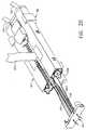
- Figure 1 is a front elevational view of the surgical device of the present invention;
- Figure 2 is an isometric view of the implement of the surgical device;
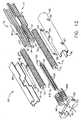
- Figure 3 is an exploded isometric view illustrating the details of the implement of the surgical device;
- Figure 4 is an exploded isometric view of the tissue clip of the implement of the surgical device;
- Figure 5 is an isometric view of the tissue clip of the implement of the surgical device placed into a target blood vessel;
- Figure 6 is a side elevational view in section of the tissue clip and the target blood vessel depicted in Figure 5;
- Figure 7 is an exploded isometric view of the frame of the implement of the surgical device;
- Figure 8 is an isometric view of the frame depicted in Figure 7 being placed together with the tissue clip and blood vessel depicted in Figure 5, also showing a partial view of the cassette inserted into the frame;
- Figure 9 is an isometric sectional view of the frame and cassette placed together with the tissue clip and blood vessel;
- Figure 10 is an isometric view of the implement of the surgical device, with a sectional view of the cassette, and showing the tissue clip inserted into a graft blood vessel;
- Figure 11 is an isometric sectional view of the implement of the surgical device with the target and graft blood vessels held together in the end-to-side manner;
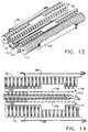
- Figure 12 is an exploded isometric view of the cassette, illustrating the details of the components;
- Figure 13 is an isometric view of the internal portion of the cassette shown in their initial alignment (before firing);
- Figure 14 is a top view of the internal portion of the cassette depicted in Figure 13 showing the initial location of the two surgical, spiral needles;
- Figure 15 is an isometric view of the implement of the surgical device holding together the target and graft blood vessels after the cassette has been completely pushed into the frame;
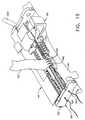
- Figure 16 is an isometric view of the implement depicted in Figure 15, with part of the implement removed for clarity, showing more clearly the formation of a passageway between the target and graft blood vessels;
- Figure 17 is a sectional view of the distal portion and blood vessels taken along line 17-17 of Figure 15;
- Figure 18 is an isometric view of the rollers of the implement being rotated by flexible shafts in order to advance the two spiral needles;
- Figure 19 is an isometric view of the implement, with a part of it removed for clarity, after the suture filaments have been placed into the target and graft blood vessels by the advancement of the spiral needles;
- Figure 20 is a perspective view of the implement of the surgical device depicting the removal of an end cover from the cassette;
- Figure 21 is an isometric view of the implement depicting the removal of the anastomosed blood vessels from the distal portion;
- Figure 22 is a front elevational view of the handle of the surgical device with a portion cutaway to view the internal components;
- Figure 23 is a proximal end elevational view of the handle of the surgical device, with a part cutaway to view the internal components;
- Figure 24 is an isometric view of an alternate embodiment of the tissue clip shown in Figure 3; and
- Figure 25 is a sectional view of the alternate embodiment of the tissue clip inside a target blood vessel such as the coronary artery.
- The drawings are not necessarily to scale.
- In the following detailed description of the present invention, a description of how the invention is used to create an end-to-side anastomosis between two blood vessels is provided concurrently. The same steps described may also be followed for creating a side-to-side anastomosis, and are not limited to only blood vessels, but may be used for joining other types of hollow organs as well.
- Referring now to the drawings wherein like numerals indicate the same element throughout the views, there is shown in Figure 1 a preferred embodiment of the present invention,
surgical device 10.Surgical device 10 includes ahandle 180 with acontrol knob 182, adrive section 130 attached to the distal end of the handle, and an implement 20 attached to the distal end of the drive section. The implement includes atissue clip 80, aframe 40, and acassette 60. In this embodiment, thedrive section 130 is flexible in order to facilitate the placement of the implement at the surgical site. - Figure 2 is a isometric view of the implement 20 of the
surgical device 10 as the implement may be assembled prior to use. Thecassette 60 is shown partially inserted into theframe 40.Right drive member 104 and leftdrive member 102 of thedrive section 130 are attached to the proximal end of theframe 40. Each of these drive members transmits a torque from thecontrol knob 182 of thehandle 180 to the implement 20. A rightsurgical suture filament 161 and a leftsurgical suture filament 163 are shown coming out of theend cover 62 of thecassette 60. Atissue button 42 on theframe 40 is used to move thetissue clip 80 as will be described later. - Figure 3 shows the implement 20 of Figure 2 with the cassette 60 (also referred to as a second member) and the tissue clip 80 (also referred to as a first member) disassembled from the
frame 40. Thecassette 60 has aright cassette housing 64 and aleft cassette housing 65 joined together on their distal ends by theend cover 62, and forming alongitudinal cassette opening 22. Thecassette 60 has a generally rectangular cross section which slidably fits into the distal end offrame 40. The cassette contains the work portion of the implement 20 for creating the anastomosis of the two blood vessels. - Still referring to Figure 3, the
frame 40 consists of aright frame housing 44 and aleft frame housing 45 joined together at their proximal ends by aplate 103, and forming alongitudinal frame opening 24. The left and right drive members, 102 and 104, enter the frame through theplate 103.Tissue button 42 is captured between the left and right frame housings, 45 and 44. Thefirst detent hole 46 and thesecond detent hole 48 are aligned to receive thefirst detent 66 of thecassette 60 in order to controllably position the cassette in theframe 40 during the use of thesurgical device 10. - Also in Figure 3, the
tissue clip 80 consists of afirst prong 82 and asecond prong 84, each prong having a tip designed for entering through a blood vessel wall. The prong tips may be used to pierce directly into the vessel wall, or a small hole could first be made in the vessel wall with a scalpel or other surgical device, and then the prong could be gently inserted. What's important to note, however, is that either method could be used while blood flow through the vessel is maintained, because the hole required for the prong is very small and mostly occluded by the prong. Slight oozing of blood is normally acceptable by surgeons during bypass procedures. - As can be seen in Figure 3, the prongs, 82 and 84, are C-channels made preferably from a stainless steel. On the
first prong 82 is attached afirst tissue stop 83. Onsecond prong 84 is attached asecond tissue stop 85. The tissue stops prevent the prongs from being inserted too far into the blood vessels. Thetissue clip 80 also includes a snap-onbeam 90 for removably attaching the tissue clip to theframe 40 of the implement 20 as depicted in Figure 2. - Turning now to Figure 4, the
tissue clip 80 is shown in an exploded, perspective view. The distal end of thefirst prong 82 fits tightly intoprong hole 93. The distal end ofsecond prong 84 attaches pivotably to prong block 98 (also referred to as a joining member) into prong slot 95, and is retained byprong pivot pin 92 fitting tightly inpin hole 99. As a result, the distal end of thesecond prong 84 is moveable towards and away fromfirst prong 82. - Figure 5 depicts the
tissue clip 80 inserted into atarget blood vessel 150. The length "L" represents the portion of thetarget blood vessel 150 to be anastomosed to the graft blood vessel (not shown). - In Figure 6, a sectional view of the
tissue clip 80 inserted into thetarget blood vessel 150 depicts how blood flow through the vessel is substantially maintainable because thefirst prong 82 is slender relative to the vessel. - Figure 7 is an exploded isometric view of the
frame 40 of the implement 20 of thesurgical device 10. This view reveals aleft drive shaft 106 and an associatedleft drive coupler 107 attached to theleft drive member 102, and rotatably captured onplate 103. Likewise, aright drive shaft 108 and an associatedright drive coupler 109 are attached toright drive member 104 and are rotatably captured onplane 103. Driveshafts frame 40 is a rightupper tissue clamp 50 which attaches to rightupper clamp recess 51 ofright frame housing 44. A leftupper tissue clamp 52 attaches to leftupper clamp recess 53 ofleft frame housing 45. Similarly left and right lower tissue clamps, 58 and 59, are mounted to the underside offrame 40. Tissue clamps 50, 52, 58, and 59 are preferably made from stainless steel and each contains a plurality offlutes 26 along one edge and extending into the longitudinal opening 24 (see Figure 3) of theframe 40.Tissue button 42 is shown with twotissue button tabs 47 for retention insideframe 40. A longitudinal,tissue button groove 43 is provided for a reason to be described. - Referring now to Figure 8, the
frame 40 containing the cassette 60 (partially cut away for clarity) is shown being placed onto thetissue clip 80 which is already inserted intotarget blood vessel 150. Thecassette 60 has already been inserted intoframe 40 at a location corresponding to when the left hook 54 (see Figure 3) of thecassette 60 is in thefirst detent hole 46 of theleft frame housing 45. - In Figure 9, the
frame 40 is attached to thetissue clip 80, aligning thetarget blood vessel 150 with the longitudinal opening 24 (see Figure 8) of the frame. The left part of the implement 20 has been removed for clarity. The snap-onbeam 90 of thetissue clip 80 is shown gripping around the sides of theframe 40. - Now turning to Figure 10, the
graft blood vessel 152 is shown placed onto thesecond prong 84 of thetissue clip 80. Thecassette 60 is still located at the same position as in Figures 8 and 9. Thesecond prong 84 is held in a center position between the right and left frame housings, 44 and 45 respectively, by thetissue bottom groove 43 of thetissue button 42. In this view, thegraft vessel 152 is shown more or less as being placed onto theprong 84 so as to result in an end-to-side anastomosis with the angle between the joined vessels being about 90 degrees. An advantage of the present invention over some of the prior art is evident here, because clearly it is permissible for the surgeon to first trim the end of thegraft vessel 152 with a beveled cut (other than perpendicular to the longitudinal axis of the vessel) and then to place the vessel onto theprong 84 at an angle favoring a more gradual approach to the junction with the target vessel. - In Figure 11, the
tissue button 42 has been pushed by the user in the distal direction to cause thesecond prong 84 to move to a position where it is parallel with thefirst prong 82. As a consequence, the end of thegraft blood vessel 152 has been brought into contact with the side of thetarget blood vessel 150. Theflutes 26 of the upper tissue clamps 50 and 52 bear against the sides of thegraft blood vessel 152 to help align and hold the graft vessel in the location shown. Similarly, theflutes 26 of the lower tissue clamps 58 and 59 bear against the sides of thetarget vessel 150 to help align and hold the target vessel in the location shown. - Figure 12 is an exploded isometric view of the
cassette 60. As described earlier, the right and left cassette housings, 64 and 65 respectively, are joined at their distal ends by theend cover 62.End tabs 76 of each of the cassette housings fit into the end cover recesses 63 to insure the assembly is properly aligned. The internal, working portion of thecassette 60 comprises aleft roller 71, aright roller 70, aleft needle guide 77, aright needle guide 78, aleft roller spring 69, aright roller spring 68, aplow 110, a leftsurgical spiral needle 162 attached tosuture filament 163, and a rightsurgical spiral needle 160 attached to aright suture filament 161. The rollers, 70 and 71, are also referred to as drivers. - Associated with the
right roller 70 is theright needle guide 78 containing a multiplicity ofvertical ribs 32 evenly spaced apart along the length of theright needle guide 78 and connected to an upper rail 33 and alower rail 34. Likewise on theleft needle guide 77 is a multiplicity ofvertical ribs 35 evenly spaced apart along the length of theleft needle guide 77 and connected to anupper rail 36 and alower rail 37. These vertical ribs, 32 and 35, are also referred to as needle paths. Each of the needle guides, 78 and 77, are preferably molded as one piece from a medical grade, rigid plastic. In addition,right needle guide 78 has a pair ofright alignment tabs 81 to locate into a pair ofright recesses 61 of theright cassette housing 64. Theleft needle guide 77 has a pair ofleft alignment tabs 79 to locate into a pair ofleft recesses 61a of theleft cassette housing 65. - Still referring to Figure 12, the
left roller spring 69 is sandwiched between theleft roller 71 and theleft cassette housing 65. Theright roller spring 68 is sandwiched between theright roller 70 and theright cassette housing 64.Left hook 54 ofroller spring 69 hooks intofirst hole 66 of theleft cassette housing 65, whileleft finger 55 of theleft roller spring 69 locates intosecond hole 67 of theleft cassette housing 65. Aright hook 56 and aright finger 57 of theright roller spring 68 attach similarly to right cassette housing 64 (holes in right cassette housing are not visible). Each roller spring is formed so as to be compressible in a direction perpendicular to the longitudinal axis of the respective roller bearing against it. The roller springs, 68 and 69 are made from a stainless steel or other spring material. - The
plow 110 shown in Figure 12 is preferably made of a rigid, medical grade plastic but could also be made of a metal such as stainless steel. Theplow 110 contains a plurality ofgrooves 120 spaced evenly along its length on each side. Theplow 110 has anupper plow rail 114 and alower plow rail 112 extending along most of its length as shown. On the proximal end ofplow 110 is a plow point 122 which bisects an upper cutting edge 116 and alower cutting edge 118. When theplow 110 is actuated as will be described, these cutting edges incise the tissue of the graft and target blood vesscts. 152 and 150, to create a passageway between them. Thegrooves 120 serve as needle guides for the two surgical, spiral needles 161 and 162. - The right and left surgical spiral needles, 160 and 162 respectively, are made from surgical steel wire and have a plurality of windings of equal diameter. The
left spiral needle 162 is wound in the opposite direction of theright spiral needle 160. The blunt ends of the spiral needles 160 and 162 are attached to suturefilaments suture filaments suture filaments cassette 60. - As shown in Figure 12, the
right roller 70 and theleft roller 71 are essentially hollow, circular cylinders with a multiplicity of annular grooves 74 evenly spaced apart along their lengths. The opposing side walls on the inside of each annular groove 74 is angled so as to form a V-shaped cross section as in a pulley for a V-belt used for automobiles, for example. This V-shape is advantageous to the present invention in that the engagement with the spiral needles, 160 and 162, are enhanced due to the wedging action of the annular grooves 74 onto the spiral needles. Each of therollers - Figure 13 is a perspective view of the working portion of the
cassette 60 as it would be assembled prior to actuation. Figure 14 is a top view of the same working portion and shows the alignment of the windings of theleft spiral needle 162, into theleft roller grooves 75 of theleft roller 71. and concurrently aligned in thegrooves 120 of theplow 110. The windings of thespiral needle 162 also mesh with thevertical ribs 35 of theleft needle guide 77. It can also be seen how theleft roller spring 69 bears against theleft roller 71 and serves to hold thespiral needle 162 between theleft roller 71 and theplow 110. The rotation of theleft roller 71 about its longitudinal axis therefore drives thespiral needle 162 to cause it to move longitudinally. The direction of the rotation would determine the direction of the longitudinal movement of thespiral needle 162. Theleft gap 154 between theleft needle guide 77 and theplow 110 is where the left edges of the graft and target blood vessels, 152 and 150, would be held together. Theleft needle guide 77 and theplow 110 are stationary while theleft roller 71 is rotated to advance theleft spiral needle 162. The same arrangement is provided on the right side of the working portion of thecassette 60, with the exception that the windings of theright spiral needle 160 are out of phase with the windings of theleft spiral needle 162. This is so the stitches created by the advancement of theleft spiral needle 162 are staggered with respect to the stitches created by theright spiral needle 160. - Figure 15 is a view of the implement 20 as it is holding the graft and target blood vessels, 152 and 150, and after the
cassette 60 has been pushed into theframe 40 to a second position. Theleft hook 54 clicks intoleft hole 66 at this position to provide feedback to the user that thecassette 60 is properly positioned. By pushing thecassette 60 into theframe 40, theplow 110 has been advanced in the proximal direction. The plow point 122 and upper and lower cutting edges, 116 and 118, have been pushed through the graft and target vessels at their juncture and created a passageway between them. In Figure 16, the fullyadvanced plow 110 can be seen after it has cut through the vessels and created aleft tissue junction 140 and a right tissue junction 142 (see Figure 17). As theplow 110 advances through the tissue, the entire working portion of thecassette 60, including the spiral needles 160 and 162, moved axially as well, thus positioning the spiral needles near the graft and target blood vessels, 152 and 150. - Figure 17 is a sectional view taken along line 17-17 of Figure 15, looking distally (towards the spiral needles). Here it can be seen how the plowing action of the
plow 110 has caused the edges of the graft and target vessel to evert partially to form the left and right tissue junctions, 140 and 142. It can also be seen how the longitudinal advancement of the rotating spiral needles will cause a series of stitches to be made through the tissue junctions, 140 and 142. The tissue junctions eventually become the peripheral edge of the passageway between the vessels. These tissue junctions must be held together firmly along their entire length as the spiral needles advance. This is accomplished by maintaining the close, parallel alignment of the first and second prongs, 82 and 84, of thetissue clip 80. In Figure 17 is shown how theupper rail 114 of theplow 110 has inserted into thesecond prong 84 of thetissue clip 80. Thelower rail 112 of theplow 110 has inserted into thefirst prong 82 of thetissue clip 80. This arrangement occurred as theplow 110 was advanced proximally by the user pushing thecassette 60 into theframe 40. - In Figure 18 is shown the left and right drive members, 102 and 104, engaging with the left and right rollers, 71 and 70. The
left drive shaft 106 slides freely into theleft roller hole 73, but because of the non-circuiar shape of theleft roller hole 73 and the similarly shapeddrive shaft 106, the rotation of the driveshaft is transmitted to the roller in the direction shown. The same arrangement is provided on the right side, except theright roller 70 is rotated in the opposite direction as theleft roller 71. - The primary reason it is desirable to rotate the rollers, 71 and 70. and hence the spiral needles, 162 and 160, in opposite directions is to maintain good suturing technique. When the surgeon uses a hand suturing technique the surgeon tries to avoid passing a needle through the coronary artery wall from the outside to the inside, but rather passes the needle from the inside to the outside. This is to minimize the amount of plaque and other built-up materials on the artery inner lining to be dislodged and allowed to migrate in the blood stream, an event which could be fatal to the patient in some cases. Again referring to Figure 16, it can be seen that by rotating the
left spiral needle 160 in the clockwise direction, and rotating theright spiral needle 162 in the counterclockwise direction, thegraft vessel 152 is penetrated first by the spiral needles, and then the needles pass through the target vessel (usually the coronary artery) from the inside to the outside. - Figure 19 is a cutaway perspective view of the implement 20 after the spiral needles, 160 and 162, have been fully advanced in the proximal direction. A plurality of sdtches, 164, have been placed into the
left tissue junction 140 and the right tissue junction 142 (not visible) and the graft and target blood vessels have been joined together. The number ofstitches 164 for this embodiment of the implement 20 can vary depending on the initial size of the graft and target blood vessels, 152 and 150. The number and spacing of the stitches can be different from what is shown in Figure 19, as those skilled in the art can see, by varying the number and spacing of needle guiding features of the implement 20, and by varying the spacing between the windings of the spiral needles, 160 and 162. - Figure 20 depicts the removal of the
end cover 62 and the attachedplow 110 from thecassette 60. While this is done, the spiral needles 160 and 162 remain in the positions as shown in Figure 19. Theend cover 62 is next pulled off the ends of thesuture filaments - Figure 21 shows the removal of the joined blood vessels, 150 and 152, from the implement 20 by gently working the implement off the vessel in the direction shown. Other surgical devices or probes may be used during this step to help free the blood vessels from the implement. As the blood vessels are drawn away from the implement, the
suture filaments tissue junctions 140 and 142 until sufficient lengths of proximal filaments is available for completing the anastomosis. - The anastomosis is completed by severing the
proximal filaments 144 near the implement 20, removing thesurgical device 10, and tying the twoproximal filaments 144 together using a conventional surgeon's knot, and then tying the twodistal filaments 146 together, again using a conventional surgeon's knot. The order of tying the knots may be reversed. The excess suture filament can then be trimmed away. - Figure 22 is a cut away view of the
handle 180 of thesurgical device 10 of the present invention. Thehandle 180 provides the means to actuate the work portion of thecassette 20 in order to advance the spiral needles. 160 and 162, as already described. Thehandle 180 of this preferred embodiment of the present invention has an elongated, in-line grip with a distal and proximal end. The handle includes acontrol knob 182 which is mounted in the proximal end and is actuated by rotation in the clockwise direction. Thedrive section 130 extends from the distal end. Theright handle cover 184 is joined to theleft handle cover 185 by a plurality of fastening pins which press tightly into mating bosses (not shown) on the inside of theleft handle cover 185. Those skilled in the art appreciate that a variety of fastening methods may be used, such as gripper pins, ultrasonically welded joints, screws, and the like. - The two flexible drive members, 104 and 102, of the
drive section 130 extend into thehandle 180. Theright drive member 104 has aflexible wire shaft 132 covered by asheath 133. Theleft drive member 102 has aflexible shaft wire 134 covered by asheath 135. The proximal end of theright drive member 104 is attached to aright pinion gear 188 which is rotatably mounted betweenhandle ribs center 189 and meshes with aleft pinion gear 193 which is attached to the distal end ofleft drive member 102 and is rotatably mounted also betweenhandle ribs Left pinion gear 193 rotates aboutcenter 194. Theleft pinion gear 194 also meshes withdrive gear 186.Drive gear 186 is mounted betweenribs control knob boss 196 by ascrew 190. Rotation of thecontrol knob 182, therefore, in the clockwise direction causes the drive gear andright pinion gear 188 to rotate in the clockwise direction and theleft pinion gear 193 to rotate in the counterclockwise direction. This gearing method provides the oppositely directed rotation of the drive members, 104 and 102. - Figure 23 shows a proximal end elevational view of the handle, with a portion of the handle covers, 184 and 185, removed to view the internal components. Counterclockwise rotation of the control knob is not desirable in the preferred embodiment of the
surgical device 10 because this rotational direction would not serve to advance the spiral needles, 160 and 162, in the proximal direction as required to join the blood vessels with suture filaments. Therefore, the counterclockwise rotation of the control knob is prevented by a one-way pawl spring 198 mounted to the inside ofleft handle cover 184 and interacting withdrive gear 186. However, thesurgical device 10 would still be operational without the pawl spring 198. Also, a manual release could also be provided on the handle to allow the surgeon to turn "off and on" the interaction of the pawl spring 198 with thedrive gear 186. - Turning now to Figure 24, an alternate embodiment of the
tissue clip 80 shown in Figure 3 is depicted. In Figure 24, aflexible tip 200 is shown attached to thefirst prong 82. Theflexible tip 82 is an elongated filament which may be solid or tubular, and is made of a flexible, biocompatible polymer such as polyethylene. It is attached to thefirst prong 82 using preferably a biocompatible adhesive, although mechanical and other methods of attachment are well-known to those skilled in the art. Theflexible tip 200 serves as a means for facilitating the introduction of the first prong into an aperture of a hollow organ, by providing a steerable and atraumatic extension to the rigidfirst prong 82. A similar flexible tip may also be provided on thesecond prong 84. In Figure 25, thefirst prong 82 of the alternate embodiment oftissue clip 80 is shown inserted into atarget blood vessel 150, such as a coronary artery. In this view, it can be seen how thefirst prong 82 enters but does not exit thetarget blood vessel 150. This usage differs from how the first embodiment of thetissue clip 80 is used as shown in Figure 6, in which thefirst prong 82 both enters and exits theblood vessel 150. The second embodiment of thetissue clip 80 requires the creation with a surgical scalpel of an aperture in the wall of thetarget blood vessel 150, prior to insertion of theflexible tip 200. For the first embodiment shown in Figure 6, creation of an aperture is not necessary. Even with the addition of an additional step when using the second embodiment, the insertion of the first prong into the blood vessel may in some cases be easier for the surgeon than when using the first embodiment without theflexible tip 200. Usage of the present invention with theflexible tip 200 is otherwise identical to that which has already been described. - While a preferred embodiment of the present invention has been shown and described herein, it will be obvious to those skilled in the art that such an embodiment is provided by way of example only. Numerous variations, changes, and substitutions will now occur to those skilled in the art without departing from the invention. Accordingly, it is intended that the invention be limited only by the scope of the appended claims.
Claims (25)
- A surgical device (20) for attaching a first hollow organ (150) to a second hollow organ (152) and creating a passageway therebetween, said surgical device (20) comprising:a) a means (82) for holding said first hollow organ (150), and a second means (84) for holding said second hollow organ (152), said first and second means (82, 84) having proximal ends attached to said surgical device (20), distal ends extending therefrom and longitudinal axis extending therebetween, said surgical device (20) including a means (42) for moving said two means for holding adjacent to one another so as to move said hollow organs (150, 152) close together;b) a plow (110) having a proximal end, a distal end extending therefrom and a longitudinal axis extending therebetween, said plow (110) is for incising at least one of said hollow organs (150, 152) so as to create a passageway between said hollow organs (150, 152); andc) a frame (90) for coupling said two means for holding (82, 84) and said plow (110) together in operational engagement, said surgical device (20) further including a means (70, 71) for driving a needle (160, 162), having a suture (161, 163) attached thereto, so as to drive said needle (160, 162) through said organs (150, 152), about said passageway thereby attaching said hollow organs (150, 152) together.
- The device (20) according to Claim 1 wherein said first and second means for holding said hollow organs comprise prongs (82, 84).
- The device (20) according to Claim 1 wherein said first and second means (82, 84) for holding said hollow organs (150, 152) comprise clips.
- The device (20) of claim 2, comprising:a) a first member (80) comprising the first prong (82) for entering a wall of said first hollow organ (150), and the second prong (84) for entering a wall of said second hollow organ (152), said prongs (82, 84) having proximal ends attached to said first member, distal ends extending therefrom and longitudinal axis extending therebetween;b) a second member (60) comprising the plow (110), said plow's proximal end anached to said second member, and said distal end of said plow is able to incise at least one of said hollow organs (150, 152) so as to create the passageway between said hollow organs (150, 152); andc) the frame (90) for coupling said first and second members together in operadonal engagement.
- The surgical device (20) of Claim 4 wherein said second member (60) further comprises two sets of needle paths extending substantially parallel to said longitudinal aixs of said plow (110) with said plow (110) disposed therebetween, said needle paths guide said needle (160, 162) along said paths so as to attach said organs (150, 152) together.
- The surgical device (20) of Claim 5 further including two spiral needles (160, 162), each having a suture (161, 163) attached thereto, engaged with said driver, said spiral needles (160, 162) passing through said needle paths and through said walls of said hollow organs (150, 152).
- The device (20) according to Claim 6, wherein said needle paths comprise a plurality of grooves on said second member, spaced apart from said plow (110).
- The device (20) according to Claim 6, wherein said needle paths comprise a plurality of grooves on either side of said plow (110) extending along its longitudinal axis.
- The surgical device (20) of Claim 4 further comprising a means for removal of said first and second hollow organs (150, 152) from said surgical device (10) after said passageway has been created and said sutures (161, 163) have been placed so as to join said hollow organs (150, 152) together.
- The surgical device (20) of Claim 4 wherein at least one of said first prong (82) and said second prong (84) has a distal, flexible tip (200) attached thereto.
- The device (20) according to Claim 4 wherein said means for moving said distal ends of said prongs (82, 84) adjacent to one another so as to move said hollow organs (150, 152) close together comprises at least one of said proximal ends of said prongs (82, 84) being attached to said first member by a pivotable connection.
- The device (20) of claim 2 comprising:a) a tissue clip (80) comprising the first prong (82) for entering a wall of said first hollow organ (150) and the second prong (84) for entering a wall of said second hollow organ (152), said prongs (82, 84) having proximal ends attached to said tissue clip, distal ends extending therefrom and longitudinal axis therebetween, at least one of said prongs being pivotable at its proximal end so that said hollow organs (150, 152) can be moved close together;b) a cassette (60) comprising the plow (140), said plow (110) having a proximal end attached to said cassette (60), and said distal end of said plow (110) is able to incise at least one of said hollow organs (150, 152) so as to create the passageway between said hollow organs (150, 152); andc) the frame (90) for coupling said tissue clip (80) and cassette (60) together in operational engagement, said surgical device further including a driver for the driving needle (160, 162), having a suture (161, 163) attached thereto, through said organs (150, 152),
- The surgical device (20) of Claim 12 wherein said cassette (60) further comprises two sets of needle paths extending substantially parallel to said longitudinal axis of said plow (110) with said plow (110) disposed therebetween, said needle paths guide said needle (160, 162) along said paths so as to attach said organs (150, 152) together.
- The surgical device (20) of Claim 13 further including two spiral needles (160, 162), each having a suture (161, 163) attached thereto, engaged with said driver, said spiral needles (160, 162) passing through said needle paths and through said walls of said hollow organs (150, 152).
- The surgical device (20) according to Claim 12, wherein said frame (90) couples said cassette (60) and tissue clip (80) in operational engagement such that said longitudinal axis of said prongs (82, 84) and said plow (110) are substantially parallel.
- The device (20) according to Claim 14, wherein said needle paths comprise a plurality of grooves on said cassette (60), spaced apart from said plow (110).
- The device (20) according to Claim 14, wherein said needle paths comprise a plurality of grooves on either side of said plow (110) extending along its longitudinal axis.
- The surgical device (20) of Claim 12 further comprising a means for removal of said first and second hollow organs (150, 152) from said surgical device (20) after said passageway has been created and said sutures (161, 163) have been placed so as to join said hollow organs (150, 152) together.
- The surgical device (20) of Claim 12 wherein at least one of said first prong (82) and said second prong (84) has a distal, flexible tip (200) attached thereto.
- The device of claim 2 comprising:a) a handle (180) attached to a proximal end of said surgical device (20) for holding said surgical device (20), and a frame (90) attached to a distal end of said surgical device (20) for coupling a tissue clip (80) and a cassette (60) together in operational engagement;b) said tissue clip comprising the first prong (82) for entering a wall of said first hollow organ (150) and the second prong for entering a wall of said second hollow organ (152), said prongs (82, 84) having proximal ends attached to said tissue clip (80), distal ends extending therefrom and longitudinal axis therebetween, at least one of said prongs (82, 84) being pivotable at its proximal end so that said hollow organs (150, 152) can be moved close together;c) said cassette (60) comprising the plow, said plow having a proximal end attached to said cassette, and said distal end of said plow (110) is able to incise at least one of said hollow organs (150, 152) so as to create the passageway between said hollow organs (150, 152), said cassette (60) further comprises two sets of needle paths extending substantially parallel to said longitudinal axis of said plow (110) with said plow (110) disposed therebetween; andd) a driver for driving a pair of spiral needles (160, 162), having a suture (161, 163) attached thereto, through said organs, said needle paths guide said needles (160, 162) along said paths so as to attach said organs (150, 152) together.
- The surgical device (20) according to Claim 20, wherein said frame (90) couples said cassette (60) and tissue clip (80) in operational engagement such that said longitudinal axis of said prongs (82, 84) and said plow (110) are substantially parallel.
- The device (20) according to Claim 20, wherein said needle paths comprise a plurality of grooves on said cassette (60), spaced apart from said plow (110).
- The device (20) according to Claim 20, wherein said needle paths comprise a plurality of grooves on either side of said plow (110) extending along its longitudinal axis.
- The surgical device (20) of Claim 20 further comprising a means for removal of said first and second hollow organs (150, 152) from said surgical device (20) after said passageway has been created and said sutures (161, 163) have been placed so as to join said hollow organs together.
- The surgical device (20) of Claim 20 wherein at least one of said first prong (82) and said second prong (84) has a distal, flexible tip (200) attached thereto.
Applications Claiming Priority (2)
| Application Number | Priority Date | Filing Date | Title |
|---|---|---|---|
| US31346 | 1987-03-26 | ||
| US09/031,346US6015416A (en) | 1998-02-26 | 1998-02-26 | Surgical anastomosis instrument |
Publications (2)
| Publication Number | Publication Date |
|---|---|
| EP0938870A1 EP0938870A1 (en) | 1999-09-01 |
| EP0938870B1true EP0938870B1 (en) | 2006-05-17 |
Family
ID=21858928
Family Applications (1)
| Application Number | Title | Priority Date | Filing Date |
|---|---|---|---|
| EP99301416AExpired - LifetimeEP0938870B1 (en) | 1998-02-26 | 1999-02-25 | Surgical anastomosis instrument |
Country Status (7)
| Country | Link |
|---|---|
| US (2) | US6015416A (en) |
| EP (1) | EP0938870B1 (en) |
| JP (1) | JPH11276494A (en) |
| AU (1) | AU742319B2 (en) |
| CA (1) | CA2262993A1 (en) |
| DE (1) | DE69931293T2 (en) |
| ES (1) | ES2264243T3 (en) |
Cited By (23)
| Publication number | Priority date | Publication date | Assignee | Title |
|---|---|---|---|---|
| US7048751B2 (en) | 2001-12-06 | 2006-05-23 | Cardica, Inc. | Implantable medical device such as an anastomosis device |
| US7063712B2 (en) | 2001-04-27 | 2006-06-20 | Cardica, Inc. | Anastomosis method |
| US7108702B2 (en) | 1998-08-12 | 2006-09-19 | Cardica, Inc. | Anastomosis device having at least one frangible member |
| US7128749B1 (en) | 1999-05-18 | 2006-10-31 | Cardica, Inc. | Sutureless closure and deployment system for connecting blood vessels |
| US7144405B2 (en) | 1999-05-18 | 2006-12-05 | Cardica, Inc. | Tissue punch |
| US7220268B2 (en) | 1999-04-16 | 2007-05-22 | Integrated Vascular Interventional Technologies, L.C. (Ivit Lc) | Methods for anastomosis of a graft vessel to a side of a receiving vessel |
| US7223274B2 (en) | 2002-01-23 | 2007-05-29 | Cardica, Inc. | Method of performing anastomosis |
| US7303570B2 (en) | 1999-07-28 | 2007-12-04 | Cardica, Inc. | Anastomosis tool having a connector holder |
| US7303569B2 (en) | 2000-10-12 | 2007-12-04 | Cardica, Inc. | Implantable superelastic anastomosis device |
| US7335216B2 (en) | 2002-01-22 | 2008-02-26 | Cardica, Inc. | Tool for creating an opening in tissue |
| US7357807B2 (en) | 1999-05-18 | 2008-04-15 | Cardica, Inc. | Integrated anastomosis tool with graft vessel attachment device and cutting device |
| US7371243B1 (en) | 1999-07-28 | 2008-05-13 | Cardica, Inc. | Surgical apparatus and method for anastomosis |
| US7455677B2 (en) | 2002-01-22 | 2008-11-25 | Cardica, Inc. | Anastomosis device having a deployable section |
| US7699859B2 (en) | 1999-07-28 | 2010-04-20 | Cardica, Inc. | Method of performing anastomosis |
| US7901417B2 (en) | 1999-04-16 | 2011-03-08 | Vital Access Corporation | Systems for forming an anastomosis with an anvil and an apparatus having at least one guide |
| US7963432B2 (en) | 2007-09-06 | 2011-06-21 | Cardica, Inc. | Driverless surgical stapler |
| US8167898B1 (en) | 2009-05-05 | 2012-05-01 | Cardica, Inc. | Flexible cutter for surgical stapler |
| US8475474B2 (en) | 1999-07-28 | 2013-07-02 | Cardica, Inc. | Anastomosis method utilizing tool with fluid-driven actuator |
| US8915934B2 (en) | 2003-11-24 | 2014-12-23 | Cardica, Inc. | Anastomosis system with anvil entry hole sealer |
| US9168039B1 (en) | 2007-09-06 | 2015-10-27 | Cardica, Inc. | Surgical stapler with staples of different sizes |
| US9345478B2 (en) | 2007-09-06 | 2016-05-24 | Cardica, Inc. | Method for surgical stapling |
| EP3572005B1 (en)* | 2016-10-17 | 2022-02-16 | LSI Solutions, Inc. | Cassette for use in a prosthetic suturing device |
| US12336702B2 (en) | 2020-03-03 | 2025-06-24 | Wright Medical Technology, Inc. | Auto-sutured allograft |
Families Citing this family (123)
| Publication number | Priority date | Publication date | Assignee | Title |
|---|---|---|---|---|
| US6440146B2 (en)* | 1996-07-23 | 2002-08-27 | United States Surgical Corporation | Anastomosis instrument and method |
| US20020019642A1 (en)* | 1996-07-23 | 2002-02-14 | Keith Milliman | Anastomosis instrument and method for performing same |
| US7223273B2 (en)* | 1996-07-23 | 2007-05-29 | Tyco Healthcare Group Lp | Anastomosis instrument and method for performing same |
| US6461320B1 (en) | 1998-08-12 | 2002-10-08 | Cardica, Inc. | Method and system for attaching a graft to a blood vessel |
| US6332889B1 (en)* | 1998-08-27 | 2001-12-25 | Onux Medical, Inc. | Surgical suturing instrument and method of use |
| US6626921B2 (en) | 1999-04-16 | 2003-09-30 | Integrated Vascular Interventional Technologies, L.C. | Externally positioned anvil apparatus for cutting anastomosis |
| US6743244B2 (en) | 1999-04-16 | 2004-06-01 | Integrated Vascular Interventional Technologies, L.C. | Soft anvil apparatus for cutting anastomosis fenestra |
| US6719769B2 (en) | 1999-11-15 | 2004-04-13 | Cardica, Inc. | Integrated anastomosis tool with graft vessel attachment device and cutting device |
| AU5143000A (en) | 1999-05-18 | 2000-12-05 | Vascular Innovations, Inc. | Implantable medical device such as an anastomosis device |
| US6179849B1 (en)* | 1999-06-10 | 2001-01-30 | Vascular Innovations, Inc. | Sutureless closure for connecting a bypass graft to a target vessel |
| US7285131B1 (en)* | 1999-07-28 | 2007-10-23 | Cardica, Inc. | System for performing anastomosis |
| US6391038B2 (en) | 1999-07-28 | 2002-05-21 | Cardica, Inc. | Anastomosis system and method for controlling a tissue site |
| US7014644B1 (en) | 1999-07-28 | 2006-03-21 | Cardica, Inc. | Tissue bonding system and method for controlling a tissue site during anastomosis |
| US7850703B2 (en) | 1999-07-28 | 2010-12-14 | Cardica, Inc. | System for performing anastomosis |
| US6527785B2 (en)* | 1999-08-03 | 2003-03-04 | Onux Medical, Inc. | Surgical suturing instrument and method of use |
| US6302892B1 (en) | 1999-08-04 | 2001-10-16 | Percardia, Inc. | Blood flow conduit delivery system and method of use |
| WO2001015607A1 (en)* | 1999-09-01 | 2001-03-08 | Origin Medsystems, Inc. | Method and apparatus for performing anastomosis |
| US6679895B1 (en)* | 1999-11-05 | 2004-01-20 | Onux Medical, Inc. | Apparatus and method for placing suture wires into tissue for the approximation and tensioning of tissue |
| US6736825B2 (en)* | 1999-12-14 | 2004-05-18 | Integrated Vascular Interventional Technologies, L C (Ivit Lc) | Paired expandable anastomosis devices and related methods |
| AU2001232902B2 (en)* | 2000-01-18 | 2004-07-08 | Covidien Lp | Anastomosis instrument and method for performing same |
| US7131979B2 (en)* | 2002-05-17 | 2006-11-07 | Dvl Acquisition Sub, Inc. | Surgical suturing instrument and method of use |
| US6514263B1 (en) | 2000-08-30 | 2003-02-04 | Ethicon Endo-Surgery, Inc. | Helical needle and suture combination having a strain relief element |
| US6530932B1 (en) | 2000-08-30 | 2003-03-11 | Ethicon Endo-Surgery, Inc. | Anastomosis device having improved tissue presentation |
| US6520973B1 (en) | 2000-08-30 | 2003-02-18 | Ethicon Endo-Surgery, Inc. | Anastomosis device having an improved needle driver |
| US6613058B1 (en) | 2000-08-30 | 2003-09-02 | Ethicon Endo-Surgery, Inc. | Anastomosis device having needle receiver for capturing the needle |
| AU2002246923A1 (en) | 2000-10-20 | 2002-07-30 | Onux Medical, Inc. | Surgical suturing instrument and method of use |
| US20050234483A1 (en)* | 2000-11-06 | 2005-10-20 | Cardica, Inc. | Unitary anastomosis device |
| US6471713B1 (en) | 2000-11-13 | 2002-10-29 | Cardica, Inc. | System for deploying an anastomosis device and method of performing anastomosis |
| US20020095166A1 (en)* | 2001-01-16 | 2002-07-18 | Jaime Vargas | Incision tensioning system and method for using the same |
| US7131980B1 (en)* | 2001-01-18 | 2006-11-07 | Dvl Acquisitions Sub, Inc. | Surgical suturing instrument and method of use |
| EP1357844B1 (en)* | 2001-01-24 | 2008-06-25 | Tyco Healthcare Group Lp | Anastomosis instrument and method for performing same |
| US6953464B2 (en) | 2001-02-21 | 2005-10-11 | Novare Surgical Systems, Inc. | Anastomosis occlusion device |
| US6620177B2 (en) | 2001-02-15 | 2003-09-16 | Novare Surgical Systems, Inc. | Anastomosis occlusion device |
| US6890338B1 (en)* | 2001-02-27 | 2005-05-10 | Origin Medsystems, Inc. | Method and apparatus for performing anastomosis using ring having tines with weak sections |
| US6902570B2 (en)* | 2001-06-08 | 2005-06-07 | Rolf Dieter Schraft | Device and method for connecting hollow organs and/or sealing wall defects in hollow organs |
| US7011668B2 (en)* | 2001-07-23 | 2006-03-14 | Dvl Acquistion Sub, Inc. | Surgical suturing instrument and method of use |
| JP2005502416A (en)* | 2001-09-14 | 2005-01-27 | オーナックス・メディカル・インコーポレーテッド | Surgical suture instrument and method of use |
| US6746456B2 (en)* | 2001-09-28 | 2004-06-08 | Ethicon, Inc. | Needle array suturing/sewing anastomosis device and method for anastomosis |
| US6860891B2 (en)* | 2001-09-28 | 2005-03-01 | Ethicen, Inc. | Arrangement and method for vascular anastomosis |
| US7464847B2 (en) | 2005-06-03 | 2008-12-16 | Tyco Healthcare Group Lp | Surgical stapler with timer and feedback display |
| US10285694B2 (en) | 2001-10-20 | 2019-05-14 | Covidien Lp | Surgical stapler with timer and feedback display |
| US8012164B1 (en) | 2002-01-22 | 2011-09-06 | Cardica, Inc. | Method and apparatus for creating an opening in the wall of a tubular vessel |
| ATE451064T1 (en)* | 2002-01-25 | 2009-12-15 | Terumo Corp | DEVICE FOR CUTTING BLOOD VESSELS |
| WO2003082125A1 (en)* | 2002-03-25 | 2003-10-09 | Onux Medical, Inc. | Surgical suturing instrument and method of use |
| US7530987B1 (en) | 2002-04-24 | 2009-05-12 | Cardica, Inc. | Surgical tool for creating an incision in a tubular vessel |
| JP2005525862A (en)* | 2002-05-17 | 2005-09-02 | オーナックス・メディカル・インコーポレーテッド | Surgical suture instrument and method of use thereof |
| US7153286B2 (en)* | 2002-05-24 | 2006-12-26 | Baxter International Inc. | Automated dialysis system |
| US7195142B2 (en)* | 2003-05-30 | 2007-03-27 | Tyco Healthcare Group Lp | End-to-end anastomosis instrument and method for performing same |
| US6769594B2 (en)* | 2002-05-31 | 2004-08-03 | Tyco Healthcare Group, Lp | End-to-end anastomosis instrument and method for performing same |
| US7267682B1 (en) | 2002-12-04 | 2007-09-11 | Cardica, Inc. | Anastomosis staple |
| AU2003243219B2 (en) | 2003-05-09 | 2009-10-29 | Covidien Lp | Anastomotic staple with fluid dispensing capillary |
| US7794471B1 (en) | 2003-06-26 | 2010-09-14 | Cardica, Inc. | Compliant anastomosis system |
| US8574246B1 (en) | 2004-06-25 | 2013-11-05 | Cardica, Inc. | Compliant anastomosis system utilizing suture |
| WO2005000127A1 (en)* | 2003-06-27 | 2005-01-06 | Zürcher Hochschule Winterthur | Apparatus for performing an anastomosis |
| US20050010241A1 (en)* | 2003-07-09 | 2005-01-13 | Keith Milliman | Anastomosis instrument and method for performing same |
| US8080023B2 (en)* | 2003-12-12 | 2011-12-20 | Vitalitec International, Inc. | Device and method for performing multiple anastomoses |
| US7585306B2 (en)* | 2003-12-24 | 2009-09-08 | Maquet Cardiovascular Llc | Anastomosis device, tools and methods of using |
| US20080269784A1 (en)* | 2003-12-24 | 2008-10-30 | Ryan Abbott | Anastomosis device, tools and methods of using |
| US20050149071A1 (en)* | 2003-12-24 | 2005-07-07 | Ryan Abbott | Anastomosis device, tools and method of using |
| US8162963B2 (en)* | 2004-06-17 | 2012-04-24 | Maquet Cardiovascular Llc | Angled anastomosis device, tools and method of using |
| US8114110B2 (en) | 2004-09-22 | 2012-02-14 | St. Jude Medical, Atrial Fibrillation Division, Inc. | Transseptal puncture needle and needle assemblies |
| US9326756B2 (en)* | 2006-05-17 | 2016-05-03 | St. Jude Medical, Atrial Fibrillation Division, Inc. | Transseptal catheterization assembly and methods |
| CH697178A5 (en)* | 2004-12-17 | 2008-06-25 | Zuercher Hochschule Winterthur | Apparatus for carrying out an anastomosis. |
| US8906039B2 (en)* | 2005-03-21 | 2014-12-09 | Design Standards Corporation | Suturing device |
| WO2006127985A2 (en)* | 2005-05-26 | 2006-11-30 | Texas Heart Institute | Surgical system and method for attaching a prosthetic vessel to a hollow structure |
| CA2609970C (en) | 2005-06-03 | 2014-08-12 | Tyco Healthcare Group Lp | Battery powered surgical instrument |
| US11291443B2 (en) | 2005-06-03 | 2022-04-05 | Covidien Lp | Surgical stapler with timer and feedback display |
| US20070142850A1 (en)* | 2005-12-15 | 2007-06-21 | David Fowler | Compression anastomosis device |
| US7815652B2 (en)* | 2006-03-21 | 2010-10-19 | Ethicon Endo-Surgery, Inc. | Surgical fastener and instrument |
| US7431188B1 (en) | 2007-03-15 | 2008-10-07 | Tyco Healthcare Group Lp | Surgical stapling apparatus with powered articulation |
| US8800837B2 (en) | 2007-04-13 | 2014-08-12 | Covidien Lp | Powered surgical instrument |
| US11259801B2 (en) | 2007-04-13 | 2022-03-01 | Covidien Lp | Powered surgical instrument |
| US7950560B2 (en) | 2007-04-13 | 2011-05-31 | Tyco Healthcare Group Lp | Powered surgical instrument |
| US20080255413A1 (en) | 2007-04-13 | 2008-10-16 | Michael Zemlok | Powered surgical instrument |
| US7823760B2 (en) | 2007-05-01 | 2010-11-02 | Tyco Healthcare Group Lp | Powered surgical stapling device platform |
| US7931660B2 (en) | 2007-05-10 | 2011-04-26 | Tyco Healthcare Group Lp | Powered tacker instrument |
| US10004507B2 (en) | 2007-06-18 | 2018-06-26 | Asfora Ip, Llc | Vascular anastomosis device and method |
| US9504469B2 (en) | 2007-06-18 | 2016-11-29 | Asfora Ip, Llc | Vascular anastomosis device and method |
| US8361092B1 (en) | 2007-06-18 | 2013-01-29 | Wilson T. Asfora | Vascular anastomosis device and method |
| US20090105815A1 (en)* | 2007-10-19 | 2009-04-23 | Matthew Krever | Push-in retainer system for use in the direct plication annuloplasty treatment of mitral valve regurgitation |
| US8197464B2 (en)* | 2007-10-19 | 2012-06-12 | Cordis Corporation | Deflecting guide catheter for use in a minimally invasive medical procedure for the treatment of mitral valve regurgitation |
| US7922063B2 (en) | 2007-10-31 | 2011-04-12 | Tyco Healthcare Group, Lp | Powered surgical instrument |
| US8771312B1 (en) | 2007-11-05 | 2014-07-08 | Cardica, Inc. | Anastomosis fasteners |
| DE102009009925B4 (en)* | 2009-02-20 | 2018-09-13 | Fraunhofer-Gesellschaft zur Förderung der angewandten Forschung e.V. | Apparatus for performing an anastomosis |
| US8821514B2 (en)* | 2009-06-08 | 2014-09-02 | Covidien Lp | Powered tack applier |
| US8459524B2 (en)* | 2009-08-14 | 2013-06-11 | Covidien Lp | Tissue fastening system for a medical device |
| US8413872B2 (en)* | 2009-10-28 | 2013-04-09 | Covidien Lp | Surgical fastening apparatus |
| US9161778B2 (en) | 2010-06-11 | 2015-10-20 | Entourage Medical Technologies, Inc. | System and method for transapical access and closure |
| US9044267B2 (en) | 2010-06-11 | 2015-06-02 | Entourage Medical Technologies, Inc. | System and method for transapical access and closure |
| DE102010035470B4 (en) | 2010-08-26 | 2015-08-13 | Fraunhofer-Gesellschaft zur Förderung der angewandten Forschung e.V. | Device for performing a side-to-side anastomosis |
| US9730690B2 (en) | 2010-09-20 | 2017-08-15 | Entourage Medical Technologies, Inc. | Method for providing surgical access |
| AU2014342300A1 (en) | 2013-10-29 | 2016-05-19 | Entourage Medical Technologies, Inc. | System for providing surgical access |
| US10092286B2 (en) | 2015-05-27 | 2018-10-09 | Covidien Lp | Suturing loading unit |
| US11311285B2 (en)* | 2015-12-21 | 2022-04-26 | Lsi Solutions, Inc. | Prosthetic suturing device and methods thereof |
| US11311295B2 (en) | 2017-05-15 | 2022-04-26 | Covidien Lp | Adaptive powered stapling algorithm with calibration factor |
| US11207066B2 (en) | 2017-10-30 | 2021-12-28 | Covidien Lp | Apparatus for endoscopic procedures |
| US12185949B2 (en) | 2017-10-30 | 2025-01-07 | Covidien Lp | Apparatus for endoscopic procedures |
| US10987104B2 (en) | 2017-10-30 | 2021-04-27 | Covidien Lp | Apparatus for endoscopic procedures |
| US11116506B2 (en)* | 2018-05-08 | 2021-09-14 | Gyrus Acmi, Inc. | Partial eversion anastomosis juncture formation and suturing |
| US11497490B2 (en) | 2018-07-09 | 2022-11-15 | Covidien Lp | Powered surgical devices including predictive motor control |
| US12137902B2 (en) | 2018-07-25 | 2024-11-12 | Covidien Lp | Adaptive anti-twitch algorithm for powered surgical devices |
| US11197734B2 (en) | 2018-10-30 | 2021-12-14 | Covidien Lp | Load sensing devices for use in surgical instruments |
| US11369372B2 (en) | 2018-11-28 | 2022-06-28 | Covidien Lp | Surgical stapler adapter with flexible cable assembly, flexible fingers, and contact clips |
| US11202635B2 (en) | 2019-02-04 | 2021-12-21 | Covidien Lp | Programmable distal tilt position of end effector for powered surgical devices |
| US11376006B2 (en) | 2019-02-06 | 2022-07-05 | Covidien Lp | End effector force measurement with digital drive circuit |
| US11219461B2 (en) | 2019-03-08 | 2022-01-11 | Covidien Lp | Strain gauge stabilization in a surgical device |
| US11439397B2 (en)* | 2019-03-27 | 2022-09-13 | Gyrus Acmi, Inc. | Suturing apparatus and method |
| GB2590138B (en) | 2019-09-30 | 2023-08-02 | Gyrus Acmi Inc | Suturing apparatus and method |
| US11458244B2 (en) | 2020-02-07 | 2022-10-04 | Covidien Lp | Irrigating surgical apparatus with positive pressure fluid |
| US11553913B2 (en) | 2020-02-11 | 2023-01-17 | Covidien Lp | Electrically-determining tissue cut with surgical stapling apparatus |
| DE102021107650A1 (en) | 2020-03-31 | 2021-09-30 | Gyrus Acmi, Inc. D/B/A Olympus Surgical Technologies America | MOVABLE SEWING DEVICE AND PROCEDURE |
| US12029470B2 (en) | 2020-05-21 | 2024-07-09 | Covidien Lp | Simultaneous RF monopolar calibration using a shared return electrode |
| US11622768B2 (en) | 2020-07-13 | 2023-04-11 | Covidien Lp | Methods and structure for confirming proper assembly of powered surgical stapling systems |
| US12193884B2 (en) | 2020-11-17 | 2025-01-14 | Covidien Lp | Contactless force measurement of motor torque in powered surgical device |
| US11744580B2 (en) | 2020-11-24 | 2023-09-05 | Covidien Lp | Long stapler reloads with continuous cartridge |
| US11653919B2 (en) | 2020-11-24 | 2023-05-23 | Covidien Lp | Stapler line reinforcement continuity |
| US12016556B2 (en) | 2021-05-03 | 2024-06-25 | Covidien Lp | Handheld electromechanical surgical system |
| US11684362B2 (en) | 2021-06-07 | 2023-06-27 | Covidien Lp | Handheld electromechanical surgical system |
| US11771432B2 (en) | 2021-06-29 | 2023-10-03 | Covidien Lp | Stapling and cutting to default values in the event of strain gauge data integrity loss |
| US12207821B2 (en)* | 2021-07-07 | 2025-01-28 | Lsi Solutions, Inc. | Device for cardiac surgery |
| US12161341B2 (en) | 2021-09-07 | 2024-12-10 | Covidien Lp | Slow speed staple and staple relaxation for stapling optimization |
| US11832823B2 (en) | 2022-02-08 | 2023-12-05 | Covidien Lp | Determination of anvil release during anastomosis |
| CN114810183A (en)* | 2022-04-29 | 2022-07-29 | 李朝举 | An air duct ring binding device at the joint of an underground air duct |
Family Cites Families (35)
| Publication number | Priority date | Publication date | Assignee | Title |
|---|---|---|---|---|
| US1181563A (en)* | 1915-04-09 | 1916-05-02 | Charles Becker | Rail-clamp. |
| US3019789A (en)* | 1958-06-30 | 1962-02-06 | Jules L Whitehill | Anastomosis clamp |
| US3019790A (en)* | 1960-07-15 | 1962-02-06 | Robert J Militana | Combination hemostat and intravenous needle |
| US3316914A (en)* | 1963-02-14 | 1967-05-02 | Michael B Collito | Surgical methods and devices for anastomosis |
| AT255638B (en)* | 1966-03-08 | 1967-07-10 | Rainer Dr Gottlob | Device for anastomosing vessels |
| US3561448A (en)* | 1968-08-30 | 1971-02-09 | Jacob Peternel | Blood vessel suturing apparatus |
| SU715082A1 (en)* | 1977-01-24 | 1980-02-15 | Всесоюзный научно-исследовательский и испытательный институт медицинской техники | Surgical suturing apparatus |
| US4345600A (en)* | 1980-08-04 | 1982-08-24 | Senco Products, Inc. | Purse-stringer |
| US4368736A (en)* | 1980-11-17 | 1983-01-18 | Kaster Robert L | Anastomotic fitting |
| US4366819A (en)* | 1980-11-17 | 1983-01-04 | Kaster Robert L | Anastomotic fitting |
| US4470415A (en)* | 1982-08-19 | 1984-09-11 | The Johns Hopkins University | Sutureless vascular anastomosis means and method |
| US4657019A (en)* | 1984-04-10 | 1987-04-14 | Idea Research Investment Fund, Inc. | Anastomosis devices and kits |
| US4593693A (en)* | 1985-04-26 | 1986-06-10 | Schenck Robert R | Methods and apparatus for anastomosing living vessels |
| US4917114A (en)* | 1986-10-17 | 1990-04-17 | United States Surgical Corporation | Surgical fastener and surgical stapling apparatus |
| US4749114A (en)* | 1986-11-10 | 1988-06-07 | United States Surgical Corporation | Purse string applicator and method of affixing a purse string |
| US4773420A (en)* | 1987-06-22 | 1988-09-27 | U.S. Surgical Corporation | Purse string applicator |
| US4803984A (en)* | 1987-07-06 | 1989-02-14 | Montefiore Hospital Association Of Western Pennsylvania | Method for performing small vessel anastomosis |
| IT1216042B (en)* | 1988-03-09 | 1990-02-22 | Carlo Rebuffat | AUTOMATIC TOOL FOR TOBACCO BAG SUTURES FOR SURGICAL USE. |
| US4931057A (en)* | 1988-03-29 | 1990-06-05 | Pfizer Hospital Products Group, Inc. | Compression anastomosis coupling assembly |
| US4997439A (en)* | 1989-01-26 | 1991-03-05 | Chen Fusen H | Surgical closure or anastomotic device |
| US4930502A (en)* | 1989-01-26 | 1990-06-05 | Chen Fusen H | Anastomosis device |
| US5089008A (en)* | 1989-01-26 | 1992-02-18 | Chen Fusen H | Surgical closure means for anastomotic device |
| US5041127A (en)* | 1989-02-27 | 1991-08-20 | Troutman Richard C | Offset point surgical needle |
| US5411481A (en)* | 1992-04-08 | 1995-05-02 | American Cyanamid Co. | Surgical purse string suturing instrument and method |
| US5425737A (en)* | 1992-04-08 | 1995-06-20 | American Cyanamid Co. | Surgical purse string suturing instrument and method |
| US5188636A (en)* | 1992-05-07 | 1993-02-23 | Ethicon, Inc. | Purse string suture instrument |
| DE4304353A1 (en)* | 1992-10-24 | 1994-04-28 | Helmut Dipl Ing Wurster | Suturing device used in endoscopic surgical operations - has helical needle with fixed non-traumatic thread held and rotated by rollers attached to instrument head extended into patients body. |
| US5356424A (en)* | 1993-02-05 | 1994-10-18 | American Cyanamid Co. | Laparoscopic suturing device |
| US5520703A (en)* | 1993-06-07 | 1996-05-28 | Essig; Mitchell N. | Laparoscopic deschamp and associated suturing technique |
| DK145593A (en)* | 1993-12-23 | 1995-06-24 | Joergen A Rygaard | Surgical double instrument for performing connection mlm. arteries (end-to-side anastomosis) |
| US5782749A (en)* | 1994-05-10 | 1998-07-21 | Riza; Erol D. | Laparoscopic surgical instrument with adjustable grip |
| US5562685A (en)* | 1994-09-16 | 1996-10-08 | General Surgical Innovations, Inc. | Surgical instrument for placing suture or fasteners |
| US5571090A (en)* | 1994-10-07 | 1996-11-05 | United States Surgical Corporation | Vascular suturing apparatus |
| US5695504A (en)* | 1995-02-24 | 1997-12-09 | Heartport, Inc. | Devices and methods for performing a vascular anastomosis |
| US6068637A (en)* | 1995-10-03 | 2000-05-30 | Cedar Sinai Medical Center | Method and devices for performing vascular anastomosis |
- 1998
- 1998-02-26USUS09/031,346patent/US6015416A/ennot_activeExpired - Lifetime
- 1999
- 1999-02-16AUAU17342/99Apatent/AU742319B2/ennot_activeExpired
- 1999-02-24CACA002262993Apatent/CA2262993A1/ennot_activeAbandoned
- 1999-02-25EPEP99301416Apatent/EP0938870B1/ennot_activeExpired - Lifetime
- 1999-02-25JPJP11048876Apatent/JPH11276494A/enactivePending
- 1999-02-25ESES99301416Tpatent/ES2264243T3/ennot_activeExpired - Lifetime
- 1999-02-25DEDE69931293Tpatent/DE69931293T2/ennot_activeExpired - Lifetime
- 1999-10-05USUS09/412,276patent/US6187019B1/ennot_activeExpired - Lifetime
Cited By (37)
| Publication number | Priority date | Publication date | Assignee | Title |
|---|---|---|---|---|
| US7108702B2 (en) | 1998-08-12 | 2006-09-19 | Cardica, Inc. | Anastomosis device having at least one frangible member |
| US7220268B2 (en) | 1999-04-16 | 2007-05-22 | Integrated Vascular Interventional Technologies, L.C. (Ivit Lc) | Methods for anastomosis of a graft vessel to a side of a receiving vessel |
| US8109949B2 (en) | 1999-04-16 | 2012-02-07 | Vital Access Corporation | Systems for forming an anastomosis |
| US7901417B2 (en) | 1999-04-16 | 2011-03-08 | Vital Access Corporation | Systems for forming an anastomosis with an anvil and an apparatus having at least one guide |
| US7922734B2 (en) | 1999-04-16 | 2011-04-12 | Vital Access Corporation | Methods for forming an anastomosis with a vessel having everted tissue |
| US7981126B2 (en) | 1999-04-16 | 2011-07-19 | Vital Access Corporation | Locking compression plate anastomosis apparatus |
| US8034064B2 (en) | 1999-04-16 | 2011-10-11 | Vital Access Corporation | Methods for forming an anastomosis opening in a side of a blood vessel |
| US7128749B1 (en) | 1999-05-18 | 2006-10-31 | Cardica, Inc. | Sutureless closure and deployment system for connecting blood vessels |
| US7175637B2 (en) | 1999-05-18 | 2007-02-13 | Cardica, Inc. | Sutureless closure and deployment system for connecting blood vessels |
| US7172608B2 (en) | 1999-05-18 | 2007-02-06 | Cardica, Inc. | Sutureless closure and deployment system for connecting blood vessels |
| US7144405B2 (en) | 1999-05-18 | 2006-12-05 | Cardica, Inc. | Tissue punch |
| US7309343B2 (en) | 1999-05-18 | 2007-12-18 | Cardica, Inc. | Method for cutting tissue |
| US7468066B2 (en) | 1999-05-18 | 2008-12-23 | Cardica, Inc. | Trocar for use in deploying an anastomosis device and method of performing anastomosis |
| US7357807B2 (en) | 1999-05-18 | 2008-04-15 | Cardica, Inc. | Integrated anastomosis tool with graft vessel attachment device and cutting device |
| US7611523B2 (en) | 1999-05-18 | 2009-11-03 | Cardica, Inc. | Method for sutureless connection of vessels |
| US7699859B2 (en) | 1999-07-28 | 2010-04-20 | Cardica, Inc. | Method of performing anastomosis |
| US8475474B2 (en) | 1999-07-28 | 2013-07-02 | Cardica, Inc. | Anastomosis method utilizing tool with fluid-driven actuator |
| US7371243B1 (en) | 1999-07-28 | 2008-05-13 | Cardica, Inc. | Surgical apparatus and method for anastomosis |
| US7303570B2 (en) | 1999-07-28 | 2007-12-04 | Cardica, Inc. | Anastomosis tool having a connector holder |
| US7303569B2 (en) | 2000-10-12 | 2007-12-04 | Cardica, Inc. | Implantable superelastic anastomosis device |
| US7063712B2 (en) | 2001-04-27 | 2006-06-20 | Cardica, Inc. | Anastomosis method |
| US7048751B2 (en) | 2001-12-06 | 2006-05-23 | Cardica, Inc. | Implantable medical device such as an anastomosis device |
| US7335216B2 (en) | 2002-01-22 | 2008-02-26 | Cardica, Inc. | Tool for creating an opening in tissue |
| US7455677B2 (en) | 2002-01-22 | 2008-11-25 | Cardica, Inc. | Anastomosis device having a deployable section |
| US7223274B2 (en) | 2002-01-23 | 2007-05-29 | Cardica, Inc. | Method of performing anastomosis |
| US8915934B2 (en) | 2003-11-24 | 2014-12-23 | Cardica, Inc. | Anastomosis system with anvil entry hole sealer |
| US7963432B2 (en) | 2007-09-06 | 2011-06-21 | Cardica, Inc. | Driverless surgical stapler |
| US8439245B2 (en) | 2007-09-06 | 2013-05-14 | Cardica, Inc. | True multi-fire endocutter |
| US8272551B2 (en) | 2007-09-06 | 2012-09-25 | Cardica, Inc. | Method of utilizing a driverless surgical stapler |
| US8679155B2 (en) | 2007-09-06 | 2014-03-25 | Cardica, Inc. | Surgical method utilizing a true multiple-fire surgical stapler |
| US8789738B2 (en) | 2007-09-06 | 2014-07-29 | Cardica, Inc. | Surgical method for stapling tissue |
| US9144427B2 (en) | 2007-09-06 | 2015-09-29 | Cardica, Inc. | Surgical method utilizing a true multiple-fire surgical stapler |
| US9168039B1 (en) | 2007-09-06 | 2015-10-27 | Cardica, Inc. | Surgical stapler with staples of different sizes |
| US9345478B2 (en) | 2007-09-06 | 2016-05-24 | Cardica, Inc. | Method for surgical stapling |
| US8167898B1 (en) | 2009-05-05 | 2012-05-01 | Cardica, Inc. | Flexible cutter for surgical stapler |
| EP3572005B1 (en)* | 2016-10-17 | 2022-02-16 | LSI Solutions, Inc. | Cassette for use in a prosthetic suturing device |
| US12336702B2 (en) | 2020-03-03 | 2025-06-24 | Wright Medical Technology, Inc. | Auto-sutured allograft |
Also Published As
| Publication number | Publication date |
|---|---|
| DE69931293D1 (en) | 2006-06-22 |
| CA2262993A1 (en) | 1999-08-26 |
| EP0938870A1 (en) | 1999-09-01 |
| JPH11276494A (en) | 1999-10-12 |
| US6187019B1 (en) | 2001-02-13 |
| AU742319B2 (en) | 2001-12-20 |
| US6015416A (en) | 2000-01-18 |
| DE69931293T2 (en) | 2007-05-24 |
| AU1734299A (en) | 1999-09-09 |
| ES2264243T3 (en) | 2006-12-16 |
Similar Documents
| Publication | Publication Date | Title |
|---|---|---|
| EP0938870B1 (en) | Surgical anastomosis instrument | |
| US6530932B1 (en) | Anastomosis device having improved tissue presentation | |
| US6514263B1 (en) | Helical needle and suture combination having a strain relief element | |
| US6520973B1 (en) | Anastomosis device having an improved needle driver | |
| US6036700A (en) | Surgical anastomosis instrument | |
| EP0931512B1 (en) | Surgical stapling instrument | |
| US6066144A (en) | Surgical anastomosis method | |
| US6613058B1 (en) | Anastomosis device having needle receiver for capturing the needle | |
| US10729442B2 (en) | Surgical stapler for aortic anastomosis | |
| US6071289A (en) | Surgical device for suturing tissue | |
| US8377082B2 (en) | Methods and apparatus for making precise incisions in body vessels | |
| US7303570B2 (en) | Anastomosis tool having a connector holder | |
| US8475474B2 (en) | Anastomosis method utilizing tool with fluid-driven actuator | |
| US6355050B1 (en) | Device and method for suturing tissue | |
| US6013027A (en) | Method for using a tissue stabilization device during surgery | |
| US7766924B1 (en) | System for performing anastomosis | |
| US7445626B2 (en) | Device and method for suturing tissue | |
| US7300444B1 (en) | Surgical system and method for connecting hollow tissue structures | |
| US20080287967A1 (en) | Device and Methods for Suturing Tissue | |
| US7371243B1 (en) | Surgical apparatus and method for anastomosis |
Legal Events
| Date | Code | Title | Description |
|---|---|---|---|
| PUAI | Public reference made under article 153(3) epc to a published international application that has entered the european phase | Free format text:ORIGINAL CODE: 0009012 | |
| AK | Designated contracting states | Kind code of ref document:A1 Designated state(s):DE ES FR IT NL | |
| AX | Request for extension of the european patent | Free format text:AL;LT;LV;MK;RO;SI | |
| 17P | Request for examination filed | Effective date:20000208 | |
| AKX | Designation fees paid | Free format text:DE ES FR IT NL | |
| 17Q | First examination report despatched | Effective date:20041209 | |
| GRAP | Despatch of communication of intention to grant a patent | Free format text:ORIGINAL CODE: EPIDOSNIGR1 | |
| GRAS | Grant fee paid | Free format text:ORIGINAL CODE: EPIDOSNIGR3 | |
| GRAA | (expected) grant | Free format text:ORIGINAL CODE: 0009210 | |
| AK | Designated contracting states | Kind code of ref document:B1 Designated state(s):DE ES FR IT NL | |
| PG25 | Lapsed in a contracting state [announced via postgrant information from national office to epo] | Ref country code:IT Free format text:LAPSE BECAUSE OF FAILURE TO SUBMIT A TRANSLATION OF THE DESCRIPTION OR TO PAY THE FEE WITHIN THE PRE;WARNING: LAPSES OF ITALIAN PATENTS WITH EFFECTIVE DATE BEFORE 2007 MAY HAVE OCCURRED AT ANY TIME BEFORE 2007. THE CORRECT EFFECTIVE DATE MAY BE DIFFERENT FROM THE ONE RECORDED.SCRIBED TIME-LIMIT Effective date:20060517 | |
| REF | Corresponds to: | Ref document number:69931293 Country of ref document:DE Date of ref document:20060622 Kind code of ref document:P | |
| REG | Reference to a national code | Ref country code:ES Ref legal event code:FG2A Ref document number:2264243 Country of ref document:ES Kind code of ref document:T3 | |
| ET | Fr: translation filed | ||
| PLBE | No opposition filed within time limit | Free format text:ORIGINAL CODE: 0009261 | |
| STAA | Information on the status of an ep patent application or granted ep patent | Free format text:STATUS: NO OPPOSITION FILED WITHIN TIME LIMIT | |
| 26N | No opposition filed | Effective date:20070220 | |
| REG | Reference to a national code | Ref country code:FR Ref legal event code:PLFP Year of fee payment:18 | |
| REG | Reference to a national code | Ref country code:FR Ref legal event code:PLFP Year of fee payment:19 | |
| REG | Reference to a national code | Ref country code:FR Ref legal event code:PLFP Year of fee payment:20 | |
| PGFP | Annual fee paid to national office [announced via postgrant information from national office to epo] | Ref country code:NL Payment date:20180214 Year of fee payment:20 | |
| PGFP | Annual fee paid to national office [announced via postgrant information from national office to epo] | Ref country code:ES Payment date:20180301 Year of fee payment:20 Ref country code:DE Payment date:20180214 Year of fee payment:20 | |
| PGFP | Annual fee paid to national office [announced via postgrant information from national office to epo] | Ref country code:IT Payment date:20180221 Year of fee payment:20 Ref country code:FR Payment date:20180111 Year of fee payment:20 | |
| REG | Reference to a national code | Ref country code:DE Ref legal event code:R071 Ref document number:69931293 Country of ref document:DE | |
| REG | Reference to a national code | Ref country code:NL Ref legal event code:MK Effective date:20190224 | |
| REG | Reference to a national code | Ref country code:ES Ref legal event code:FD2A Effective date:20200803 | |
| PG25 | Lapsed in a contracting state [announced via postgrant information from national office to epo] | Ref country code:ES Free format text:LAPSE BECAUSE OF EXPIRATION OF PROTECTION Effective date:20190226 |