EP0934051B1 - Cold pack for vials containing medicine - Google Patents
Cold pack for vials containing medicineDownload PDFInfo
- Publication number
- EP0934051B1 EP0934051B1EP97942484AEP97942484AEP0934051B1EP 0934051 B1EP0934051 B1EP 0934051B1EP 97942484 AEP97942484 AEP 97942484AEP 97942484 AEP97942484 AEP 97942484AEP 0934051 B1EP0934051 B1EP 0934051B1
- Authority
- EP
- European Patent Office
- Prior art keywords
- holder
- depression
- segment
- storage space
- cover members
- Prior art date
- Legal status (The legal status is an assumption and is not a legal conclusion. Google has not performed a legal analysis and makes no representation as to the accuracy of the status listed.)
- Expired - Lifetime
Links
- 239000003814drugSubstances0.000titleclaimsabstractdescription23
- 239000007788liquidSubstances0.000claimsabstractdescription12
- 230000002093peripheral effectEffects0.000claims3
- 238000000926separation methodMethods0.000claims2
- 230000013940response to freezingEffects0.000claims1
- 238000001816coolingMethods0.000abstractdescription8
- 229940079593drugDrugs0.000description9
- 238000005057refrigerationMethods0.000description4
- 239000012815thermoplastic materialSubstances0.000description3
- 230000007704transitionEffects0.000description3
- 230000001154acute effectEffects0.000description2
- 239000011324beadSubstances0.000description2
- NOESYZHRGYRDHS-UHFFFAOYSA-NinsulinChemical compoundN1C(=O)C(NC(=O)C(CCC(N)=O)NC(=O)C(CCC(O)=O)NC(=O)C(C(C)C)NC(=O)C(NC(=O)CN)C(C)CC)CSSCC(C(NC(CO)C(=O)NC(CC(C)C)C(=O)NC(CC=2C=CC(O)=CC=2)C(=O)NC(CCC(N)=O)C(=O)NC(CC(C)C)C(=O)NC(CCC(O)=O)C(=O)NC(CC(N)=O)C(=O)NC(CC=2C=CC(O)=CC=2)C(=O)NC(CSSCC(NC(=O)C(C(C)C)NC(=O)C(CC(C)C)NC(=O)C(CC=2C=CC(O)=CC=2)NC(=O)C(CC(C)C)NC(=O)C(C)NC(=O)C(CCC(O)=O)NC(=O)C(C(C)C)NC(=O)C(CC(C)C)NC(=O)C(CC=2NC=NC=2)NC(=O)C(CO)NC(=O)CNC2=O)C(=O)NCC(=O)NC(CCC(O)=O)C(=O)NC(CCCNC(N)=N)C(=O)NCC(=O)NC(CC=3C=CC=CC=3)C(=O)NC(CC=3C=CC=CC=3)C(=O)NC(CC=3C=CC(O)=CC=3)C(=O)NC(C(C)O)C(=O)N3C(CCC3)C(=O)NC(CCCCN)C(=O)NC(C)C(O)=O)C(=O)NC(CC(N)=O)C(O)=O)=O)NC(=O)C(C(C)CC)NC(=O)C(CO)NC(=O)C(C(C)O)NC(=O)C1CSSCC2NC(=O)C(CC(C)C)NC(=O)C(NC(=O)C(CCC(N)=O)NC(=O)C(CC(N)=O)NC(=O)C(NC(=O)C(N)CC=1C=CC=CC=1)C(C)C)CC1=CN=CN1NOESYZHRGYRDHS-UHFFFAOYSA-N0.000description2
- 230000002452interceptive effectEffects0.000description2
- 102000004877InsulinHuman genes0.000description1
- 108090001061InsulinProteins0.000description1
- 238000005713Midland reduction reactionMethods0.000description1
- 238000004140cleaningMethods0.000description1
- 238000010276constructionMethods0.000description1
- 239000002826coolantSubstances0.000description1
- 230000000694effectsEffects0.000description1
- 238000007710freezingMethods0.000description1
- 230000008014freezingEffects0.000description1
- 230000008676importEffects0.000description1
- 229940125396insulinDrugs0.000description1
- 238000000034methodMethods0.000description1
- 238000012986modificationMethods0.000description1
- 230000004048modificationEffects0.000description1
- 230000008569processEffects0.000description1
- 230000008707rearrangementEffects0.000description1
- 239000003507refrigerantSubstances0.000description1
- 238000007789sealingMethods0.000description1
- 239000000126substanceSubstances0.000description1
- 229920001169thermoplasticPolymers0.000description1
- 239000004416thermosoftening plasticSubstances0.000description1
- 238000007666vacuum formingMethods0.000description1
- XLYOFNOQVPJJNP-UHFFFAOYSA-NwaterSubstancesOXLYOFNOQVPJJNP-UHFFFAOYSA-N0.000description1
Images


Classifications
- A—HUMAN NECESSITIES
- A61—MEDICAL OR VETERINARY SCIENCE; HYGIENE
- A61J—CONTAINERS SPECIALLY ADAPTED FOR MEDICAL OR PHARMACEUTICAL PURPOSES; DEVICES OR METHODS SPECIALLY ADAPTED FOR BRINGING PHARMACEUTICAL PRODUCTS INTO PARTICULAR PHYSICAL OR ADMINISTERING FORMS; DEVICES FOR ADMINISTERING FOOD OR MEDICINES ORALLY; BABY COMFORTERS; DEVICES FOR RECEIVING SPITTLE
- A61J1/00—Containers specially adapted for medical or pharmaceutical purposes
- A61J1/14—Details; Accessories therefor
- A61J1/16—Holders for containers
- A61J1/165—Cooled holders, e.g. for medications, insulin, blood or plasma
- F—MECHANICAL ENGINEERING; LIGHTING; HEATING; WEAPONS; BLASTING
- F25—REFRIGERATION OR COOLING; COMBINED HEATING AND REFRIGERATION SYSTEMS; HEAT PUMP SYSTEMS; MANUFACTURE OR STORAGE OF ICE; LIQUEFACTION SOLIDIFICATION OF GASES
- F25D—REFRIGERATORS; COLD ROOMS; ICE-BOXES; COOLING OR FREEZING APPARATUS NOT OTHERWISE PROVIDED FOR
- F25D3/00—Devices using other cold materials; Devices using cold-storage bodies
- F25D3/02—Devices using other cold materials; Devices using cold-storage bodies using ice, e.g. ice-boxes
- F25D3/06—Movable containers
- F25D3/08—Movable containers portable, i.e. adapted to be carried personally
- F—MECHANICAL ENGINEERING; LIGHTING; HEATING; WEAPONS; BLASTING
- F25—REFRIGERATION OR COOLING; COMBINED HEATING AND REFRIGERATION SYSTEMS; HEAT PUMP SYSTEMS; MANUFACTURE OR STORAGE OF ICE; LIQUEFACTION SOLIDIFICATION OF GASES
- F25D—REFRIGERATORS; COLD ROOMS; ICE-BOXES; COOLING OR FREEZING APPARATUS NOT OTHERWISE PROVIDED FOR
- F25D2331/00—Details or arrangements of other cooling or freezing apparatus not provided for in other groups of this subclass
- F25D2331/80—Type of cooled receptacles
- F25D2331/801—Bags
- F25D2331/8014—Bags for medical use
- G—PHYSICS
- G01—MEASURING; TESTING
- G01N—INVESTIGATING OR ANALYSING MATERIALS BY DETERMINING THEIR CHEMICAL OR PHYSICAL PROPERTIES
- G01N1/00—Sampling; Preparing specimens for investigation
- G01N2001/002—Devices for supplying or distributing samples to an analysing apparatus
- G01N2001/005—Packages for mailing or similar transport of samples
Definitions
- the present inventionrelates to a portable cold pack for medicinal vials and, more particularly, to a cold pack for use by emergency medical technicians and ambulatory services.
- Certain medicinessuch as insulin, are temperature-sensitive and must be refrigerated. Refrigeration of these medicines causes particular storage difficulties for emergency medical personnel. Ambulances are equipped with heaters, but they are not commonly equipped with refrigeration units.
- Refrigerating medicines in conventional cooling packages and coolershas many drawbacks, particularly when used with ambulatory services.
- conventional cooling packages and coolersare bulky and difficult to manipulate.
- quick and efficient access to the medicine in the cooling packages and coolersis restricted by the cooling packages and cooler per se.
- the chilling mediummay spill.
- US-A-4393975discloses apparatus for retaining and refrigerating a lipstick container.
- the apparatuscomprises a case having a cover, fastened to a bottom section, and including a retainer defining a compartment between the case and the dispenser.
- a reusable refrigerantis placed within the container, to keep the lipstick dispenser cool.
- FR-A-1254986discloses a bag having insulated walls. A separate independent holder is mounted on one of the walls.
- FR-A-2 635 580discloses a package according to the preamble of claim 1.
- a portable package according to the present inventionis defined in claim 1.
- the packageis a portable cold pack, in which a medicine can be held below the temperature at which it degrades.
- the medicinecan be held below the critical temperature for a substantial period of time.
- the cold packcan easily be used in an emergency, because the medicinal vials are quickly and easily accessible to medical personnel.
- the devicecan also be easily and quickly closed and sealed, because time is important, not only when accessing a medicine for the patient, but also when cleaning up the treatment site and transporting the patient for further medical attention.
- the cold packmay be placed within a reclosable insulated bag. This will enhance the cooling ability of the cold pack.
- the insulated bagcan be attached to or placed in the drug case used by medical personnel to transport medicines to the patient's location.
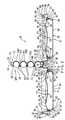
- FIG. 1shows a cold pack 10 which includes a base 11, a hollow, thin-walled housing 12, and a medicinal vial holder 13. All components of the cold pack 10 are made of a uniformly thick thermoplastic material and shaped during a vacuum forming process.
- the base 11has a pair of upstanding and upwardly converging side walls 14 and a pair of upstanding and upwardly converging side end walls 15, all contained in respective planes inclined to the vertical. Upper ends of each of the walls 14, 15 terminate in a common plane and are connected by a top wall 16.
- the top wall 16has a socket-like depression 17 formed therein which is adapted to removably receive the vial holder 13.
- a hinge 20is integrally formed to and extends laterally along a bottom edge of each of the side walls 14.
- the socket-like depression 17has opposing side walls 21, 22 and opposing end walls 23 extending between the side walls 21, 22. While the socket-like depression 17 may be of any geometric shape, in the preferred embodiment, the side walls 21 and 22 are generally parallel to each other. Further, one of the side walls 21 is shorter in height than the other side wall 22 so that a bottom wall 24 of the socket-like depression 17 connected to the bottom edge of the side walls 21, 22 is inclined therebetween.
- the end walls 23are generally convergingly inclined from the sidewall 22 toward the side wall 21.
- the base 11additionally has a facing member 25 formed on and protrudes outwardly from each of the end walls 15.
- Each of the facing members 25has plural facing surfaces 26 thereon angularly related to each other.
- two angularly related surfaces 26are provided to form an inverted V-shape in cross section.
- the housing 12in the preferred embodiment, includes two cover members 30, 31 which are integrally formed with each of the hinges 20, and are each pivotal about the respective hinges between first and second positions.
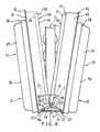
- the first positionis shown in Figures 1 and 2, whereas the second position is shown in Figure 3.
- the cover member 30has a hollow thin walled section 32 defined by a base sheet 33 formed into a generally rectangularly shaped receptacle 34 having upstanding and opposing end walls 36 and 37, as well as upstanding and opposing side walls 38 and 39 connecting the end walls.
- a bottom wall 40connects bottom edges of each of the side and end walls 36-39 through correspondingly radiussed corner sections.
- the hinge 20interconnects the end wall 36 to the base 11 to facilitate the aforesaid pivotal movement.
- a skirt 45projects outwardly from an upper edge of the side and end walls 37-39 and downwardly along an outside facing surface of the side walls 38, 39 and the end wall 37 remote from the hinge 20.
- a lower outer edge of the skirt 45forms an outwardly extending flange 46.
- the upper edge of the side walls 38, 39 and the end wall 37 remote from the hinge 20are coplanar and terminate a distance above the level of the hinge 20 as shown in Figure 2.
- End portions 47 of the side walls 38 and 39 adjacent to and facing the base 11each define a facing surface 48.
- Each facing surface 48is conformed to the respective facing surface 26 on the facing member 25 of the base 11 so that as the cover member 30 pivots about the hinge 20, the opposing facing surfaces 26 and 48 will be in a close juxtaposition to form a loose seal, especially when the cover member 30 is pivoted 90° from the open or first position shown in Figure 2 to the closed or second position shown in Figure 3.
- the angularly related facing surfaces 26 and 48additionally allow the cover 23 to pivot through the 90° movement without interfering with the structure of the hinge 20.
- a bead or tongue 50having an uppermost flat surface segment 51 extending parallel to the bottom wall 40 and an acute angle stepped segment 52 forming the upper edge of the skirt 45.
- a first wall surface 53 of the stepped segment 52is oriented generally parallel to the flat surface segment 51 and is contiguous with the skirt 45 whereas a second wall surface 54 is inclined to the vertical.
- the edge joining the inclined wall surface 54 to the flat surface segment 51defines a lip 55.
- the region of the cover member 30 generally adjacent and above the level of the hinge 20is open so that the end portion 47 of the side walls 38, 39 adjacent the hinge 20 straddle about half the left to right dimension of the base 11 illustrated in Figure 2 when the cover member is moved to the closed position.
- the uppermost flat surface 51terminates shortly before the end portion 47 of the side walls 38, 39 to allow the stepped segment 52 to extend between the flat surface 51 and the end portion 47.
- the inclined wall surface 54 of the stepped segment 52has a portion 57 inclined with respect to the vertical extending from a portion 56 of the wall surface 53 to the uppermost flat surface segment 51.
- the interior of the rectangularly shapped receptacle 34includes on the interior walls thereof at about a mid-height level, here on the end walls 36 and 37 and the immediately adjacent area of the contiguous side walls 38 and 39, structure defining spaced lower and upper ledges 58 and 59.
- Each respective ledge 58 and 59includes a lower stepped configuration 60 and an upper stepped configuration 61, respectively.
- a wall section 62is received on the ledges 58 and 59 and is cemented in place.
- the wall section 62includes a sheet of uniformly thick thermoplastic material having a perimeter thereof formed into a U-shaped flange 63, one leg 64 of the U-shaped flange being contiguous with the sheet.
- the other leg 65 of the U-shaped flangeterminates at an upper edge thereof in an outwardly extending flange 66 adapted to rest on an upper surface area 67 of the upper ledge 59.
- the wall section 62 inside the aforesaid perimeterincludes a pair of convergingly inclined sections 68 and 69 extending upwardly from opposite ends thereof adjacent the end walls 36 and 37.
- the wall section 62also includes a pair of convergingly inclined sections 70 and 71 extending upwardly from opposite sides adjacent the side walls 38 and 39.
- the pair of convergingly inclined sections 70, 71generally mirror each other about a center line of the wall section 62.
- the upper edges 72, 73, 74 and 75 of the four inclined sections 68, 69, 70 and 71, respectively,are coplanar and are contiguous with a wall segment 76 forming generally a centrally disposed depression or pocket 77.
- the wall segment 76is in the general form of a segment of a sphere or like surface area. Further, the wall segment 76 is yieldable to forces applied to a bulbous side 78 thereof. In this embodiment, the bulbous side 78 faces and opposes the bottom wall 40 of the rectangularly shaped receptacle 34 in the cover member 30.
- a space or cavity 80is defined between the bulbous side 78 and the bottom wall 40 of the receptacle 34.
- a bag 81 of refreezable liquidis placed into the cavity 80 and occupies a majority of the space therein.
- Such bags 81 of refreezable liquidare marketed by Mid-Lands Chemical Company, Inc. of Omaha, Iowa under the trademark POLAR PACK®.
- the cover member 31has a hollow thin walled section 82 defined by the base sheet 33 formed into a generally rectangularly shaped receptacle 84 having upstanding and opposing end walls 86 and 87, as well as upstanding and opposing side walls 88 and 89 connecting the end walls 86, 87.
- a bottom wall 90connects the bottom edges of each of the side and end walls 86-89 through correspondingly radiussed corner sections.
- the hinge 20interconnects the end wall 86 to the base 11 to facilitate the aforesaid pivotal movement.
- a skirt 95projects outwardly from an upper edge of the side and end walls 87-89 and downwardly along an outside facing surface of the side walls 88, 89 and the end wall 87 remote from the hinge 20.
- the lower outer edge of the skirt 95forms an outwardly extending flange 96.
- the upper edge of the side walls 88, 89 and the end wall 87 remote from the hinge 20are coplanar and terminate a distance above the level of the hinge 20 as shown in Figure 2. End portions 97 of the side walls 88 and 89 are adjacent to and face the base 11 each defining a facing surface 98.
- Each facing surface 98is conformed to the respective facing surface 26 on the facing member 25 so that as the cover member 31 pivots about hinge 20, the opposing facing surfaces 26 and 98 will be in close juxtaposition to form a loose seal, especially when the cover member 31 is pivoted 90° from the open or first position shown in Figure 2 to the closed or second position shown in Figure 3.
- the seal between the opposed facing surfaces 26 and 98need not be air tight. It is important, however, that the angularly related surfaces 26 and 98 allow the cover 31 to pivot through the 90° movement without interfering with the structure of the hinge 20.
- the juncture between the upper edges of the side walls 88, 89 and the end wall 87 remote from the hinge 20 and the skirt 95defines a bead or tongue 100 having an uppermost flat surface segment 101 extending parallel to the bottom wall 90 integrally connected to the skirt 95 and an acute angle stepped segment 102 forming the upper portion of side walls 88, 89 and end wall 87.
- One wall surface 103 of the stepped segment 102is oriented generally parallel to the flat surface segment 101 and is contiguous with the side walls 88, 89 and end wall 87, whereas the other wall surface 104 is inclined to the vertical.
- the edge joining the other wall surface 104 to the uppermost flat surface segment 101defines a lip 105.
- the region of the cover member 31 generally adjacent to and above the level of the hinge 20is open so that an end portion 97 of the side walls 88, 89 adjacent the hinge 20 straddle the width of the base 11 when the cover member 31 is moved to the closed position.
- the uppermost surface 101 and the stepped segment 102 on both side walls 88 and 89form a right angle corner as at 106 adjacent the hinge 20.
- the facing surface 98extends on those right angle segments between the uppermost flat surface 101 and the hinge 20 as shown in Figure 1.
- a portion 107 of the inclined wall surface 104 of the stepped segment 102extends from the uppermost flat surface 101 to the wall surface 103 and faces the interior of cover member 31.
- the interior of the rectangularly shaped receptacle 84 of the cover member 31is identically shaped to interior of the first described cover member 30.
- the same reference numeralshave been used to denote the identically formed individual structural features in conjunction with the receptacle 84. Further description of these identically formed features is deemed to be superfluous.
- the medicinal vial holder 13includes a sheet of uniformly thick thermoplastic material formed into a rectangular shaped tray segment 109 having a compartmented depression region 110 thereon.
- Each compartment 110A, 110B, 110C and 110D of the compartmented region 110 on the tray segment 109are identical and includes a generally cylindrical bottom wall 111 terminating adjacent the upper edges thereof in integrally formed locking lugs 112 which protrude into the region normally occupied by a medicine containing vial so as to be adapted to yieldingly hold a vial in the compartment.
- each lug 112is smaller in length than a length of the bottom wall 111.
- End walls 113are formed at the respective ends of the bottom walls 111.
- each of the bottom walls 111 and end walls 113are all coplanar and transition from an uppermost flat surface 118 into a peripherally outwardly extending skirt 114 around the entirety of the holder 13.
- the skirt 114includes an inclined wall segment 115 on each of the four sides of the rectangle and which are joined together at each of the four corners.
- the lower edge of the skirt 114is formed into an outwardly extending stiffening flange 116.
- the structure of the skirts 114 on each of the long sides and narrow sidesis elastically yieldable.
- Either of the narrow ends of the tray segment 109is designatable as a holder segment 117 conforming in shape to the shape of the socket-like depression 17 on the base 11. That is, the outward inclination of the wall segment 115 at the narrow end is generally similarly inclined to the bottom wall 24 of the socket-like depression 17. Further, the spacing between the coplanar surface 118 extending between the upper edges of the skirts 114 and the upper edges of the bottom walls 111 and an opposite facing surface 119 on a side of the flange 116 remote from the surface 118 is nearly equal to the spacing between the side walls 21 and 22 of the socket-like depression 17.
- the wall segments 115 of the skirt 114 on opposite sides of the long sides of the tray segment 109are inclined at an angle that is generally parallel to the end walls 23 of the socket-like depression 17 when a longitudinal axis of the holder 13 is oriented perpendicular to the top wall 16 of the base member 11.
- a narrow end of the tray segment 109, namely, the holder segment 117 thereofis receivable in the socket-like depression 17 as shown in the drawings.
- the fit between the holder segment 117 and the walls 21-24 of the socket-like depression 17is snug.
- the holder 13In use the holder 13 is received by the socket-like depression 17.
- the flange 116 on the long side side wall portions of the wall segment 115 of the holder 13is slightly wider than the spacing between the end walls 23 of the socket-like depression 17.
- a slight application of forceis applied to the holder 13 to deform the elastically yieldable wall segments 115 of the long side skirts 114 due to the long side flanges 116 contacting the end walls 23 of the socket-like depression 17.
- the elastically yieldable wall segments 115continue to press outwardly onto the end walls 23 to maintain the contact between the flanges 116 at the end thereof against the end walls 23 to thereby enhance the snug fit of the holder 13 in the depression 17 in the base 11.
- the holder 13When the holder 13 is to be removed from the depression 17, it may be pulled upwardly out of the depression 17. Alternatively, and if the holder 13 is held quite firmly in the depression 17, it may be necessary for a person (user) to pivot the holder 13 by gripping the holder above the holder segment 117 positioned in the depression 17 urging the exposed tray segment 109 of the holder 13 clockwise as shown in Figure 2 about a pivot axis defined by the juncture between the surface 119 of the flange 116 and the upper edge segment of the side wall 22 of the depression 17 so as to easily overcome the snug fit and, facilitate removal of the holder 13 from the depression 17.
- the lips 55 and 105 and associated stepped segments 52 and 102are nested with one another to form a clasp 122 holding the cover members 30 and 31 in the closed position.
- the surfaces 51 and 101face one another when the cover 30 and 31 are in the closed position.
- the differing depths of the side walls 21, 22 of depression 17allows the easy removal of the holder 13 from the depression 17 by pivoting the holder clockwise toward the cover member 31.
- the shorter depth of the side wall 21allows the coplanar surface 118 of the holder segment 117 to be easily removed from the depression 17 during the clockwise movement.
- the side wall 22has a depth into the depression greater than side wall 21 which prevents the holder 13 from pivoting counterclockwise toward the cover member 30.
- the usercan grasp the flanges 46, 96 and/or the skirts 45, 95 to apply opposing separating forces to each cover member 30, 31.
- the flexibility of the thermoplastic constructionallows the lips 55, 105 to thereby be forced past each other and the open position is attained by rotating the cover members 90° in respective directions away from the holder 13.
- the cold pack 10may also be opened by placing the cold pack on the bottom wall 40 of the cover member 30, then rotating cover member 31 through 180° so as to lie in the same plane as the cover member 31.
- the holder 13 in the depression 17will resist falling out of the depression 17 due to the aforesaid snug fit in the depression.
- the cover members 30, 31are rotated 90° about the hinges 20 toward the holder 13.
- the portions 57 of the inclined wall surface 54slidingly engage the portions 107 of inclined wall segment 104 of each of the right angle corner segments 106.
- the sliding engagement of the portion 57 and the wall segment 107effects an alignment of the lips 55 and 105 to facilitate them snapping past each other locking the cold pack 10 into the closed or second position.
- the portion 56 of the surface 53faces and opposes the right angled portion of the flat surface segment 101.
- a storage space 120is defined by and between the interior surfaces of the side walls 38, 39, 88, 89 above ( Figure 2) the wall sections 62 and the interior surfaces of the end walls 37, 87 for cold storing the holder 13 positioned in the socket-like depression 17.
- the storage space 120is essentially insulated from the outside environment and stores the temperature sensitive medicine below its critical temperature for a substantial period of time.
- the cold pack 10can be reused by placing the entire cold pack 10 in a freezer and refreezing the liquid in the bags 81 positioned therein.
- the use of the ice packs or bags 81 to provide the coolanthas a serious drawback, namely, the ice bags expand when frozen.
- the depression or pocket 77 formed by the wall segment 76will yield to the expanding ice bag during the freezing thereof.
- the wall segment 76will expand to the broken line showing at 121 in Figure 3 and to a close juxtaposition to the medicine containing vials on one side of the holder 13 and the surface 119 on the other side of the holder 13.
- the medicinal vials Vare of a commonly used shape having a cylindrical liquid containing main body B with a reduced diameter neck N extending from one end of the body.
- a cap Cis positioned on an end of the neck remote from the body for sealing the liquid medicine within the vial.
Landscapes
- Health & Medical Sciences (AREA)
- Engineering & Computer Science (AREA)
- General Health & Medical Sciences (AREA)
- Pharmacology & Pharmacy (AREA)
- Life Sciences & Earth Sciences (AREA)
- Public Health (AREA)
- Veterinary Medicine (AREA)
- Animal Behavior & Ethology (AREA)
- Combustion & Propulsion (AREA)
- Chemical & Material Sciences (AREA)
- Physics & Mathematics (AREA)
- Mechanical Engineering (AREA)
- Thermal Sciences (AREA)
- General Engineering & Computer Science (AREA)
- Hematology (AREA)
- Medical Preparation Storing Or Oral Administration Devices (AREA)
- Packages (AREA)
- Medicinal Preparation (AREA)
Abstract
Description
The first position is shown in Figures 1 and 2, whereas the second position isshown in Figure 3. The
Claims (7)
- A portable package (10) for cold storing and transporting medicine stored invials, comprising a housing (12) having abase (11) and first and second thin-walled covermembers (30,31) each secured to the base on opposite sides thereof by parallel hinges(20) so that the cover members can each be pivoted with respect to the base between afirst position at which each cover member exposes a surface area forming a depression(77) opening outwardly in a common direction, and a second position at which therespective depressions face one another to define a storage space, wherein the covermembers each define a cavity (32) having a freezable liquid therein, and the packagefurther comprises closure means (122) for providing access to and removal ofthe holderfrom the storage space,
characterised in that the package comprises a holder (13) for holding at least onevial, the base has a support means thereon for fixedly and removably supporting theholder in the storage space and in close juxtaposition to the interior surfaces of the covermembers, the peripheral edges of the cover members tightly engage one another in thesecond position - A package according to claim 1, wherein the closure means comprises a lockingtongue and groove means on the cover members, for latching the cover memberstogether to enclose the holder securely within the storage space.
- A package according to claim 1 or claim 2, wherein a segment of the cavity walldefining said surface area and forming the depression on each cover member has ayieldable characteristic in response to freezing of the liquid and a resulting expansion ofvolume occupied by the frozen liquid, so that the surface area is closer to the holderwhen the liquid is frozen than when it is in the liquid state.
- A package according to claim 3, which additionally comprises, in the holder, atleast one vial whose peripheral surface is spaced from each said surface area a sufficientdistance to allow yielding of said surface area when the liquid is frozen and to allowengagement of the peripheral edges of the closure members when in the second position.
- A package according to any preceding claim, wherein the support means includesa socket depression (17) opening outwardly, in said common direction, and the holder includes a shaped segment conforming to and being removably received in the socketdepression as well as, contiguous with the shaped segment, a tray segment (109) havinga compartmented depression (110) thereon for medicinal vials, and opening outwardlyin a direction normal to said common direction, the tray segment being fully housed inthe storage space when the cover members are in said second position.
- A package according to claim 5, wherein the compartmented depression includesplural parallel separation walls and locking rib means (112), whereby multiple vials canbe held between mutually adjacent pairs of the separation walls with limited relativemotion and contact between the vials.
- A package according to any preceding claim, further comprising a readilygrippable flange (46,96) integrally extending from an exterior of each cover member.
Priority Applications (1)
| Application Number | Priority Date | Filing Date | Title |
|---|---|---|---|
| SI9730202TSI0934051T1 (en) | 1996-09-23 | 1997-09-19 | Cold pack for vials containing medicine |
Applications Claiming Priority (3)
| Application Number | Priority Date | Filing Date | Title |
|---|---|---|---|
| US2656596P | 1996-09-23 | 1996-09-23 | |
| US2656P | 1996-09-23 | ||
| PCT/US1997/016347WO1998011861A1 (en) | 1996-09-23 | 1997-09-19 | Cold pack for vials containing medicine |
Publications (2)
| Publication Number | Publication Date |
|---|---|
| EP0934051A1 EP0934051A1 (en) | 1999-08-11 |
| EP0934051B1true EP0934051B1 (en) | 2001-08-08 |
Family
ID=21832544
Family Applications (1)
| Application Number | Title | Priority Date | Filing Date |
|---|---|---|---|
| EP97942484AExpired - LifetimeEP0934051B1 (en) | 1996-09-23 | 1997-09-19 | Cold pack for vials containing medicine |
Country Status (12)
| Country | Link |
|---|---|
| US (1) | US5956968A (en) |
| EP (1) | EP0934051B1 (en) |
| JP (1) | JP2001501106A (en) |
| KR (1) | KR100506446B1 (en) |
| AT (1) | ATE203893T1 (en) |
| AU (1) | AU717958B2 (en) |
| CA (1) | CA2266356C (en) |
| DK (1) | DK0934051T3 (en) |
| ES (1) | ES2159877T3 (en) |
| GR (1) | GR3037089T3 (en) |
| PT (1) | PT934051E (en) |
| WO (1) | WO1998011861A1 (en) |
Families Citing this family (34)
| Publication number | Priority date | Publication date | Assignee | Title |
|---|---|---|---|---|
| FR2781461B1 (en)* | 1998-07-22 | 2000-10-13 | Transports Laprie Biotrans | DEVICE FOR TRANSPORTING FRAGILE OBJECTS AND IN PARTICULAR BLOOD POCKETS |
| CA2457141A1 (en)* | 2000-08-28 | 2002-03-07 | John K. Stevens | A high security wireless key for asynchronous delivery drop boxes |
| US6658903B1 (en)* | 2000-09-27 | 2003-12-09 | Mcshane James P. | Thermally insulated lock box and lock therefor |
| US6412545B1 (en)* | 2001-08-16 | 2002-07-02 | Paul C. Buff | Carrying case for protecting heat sensitive materials |
| US6745785B2 (en)* | 2002-01-18 | 2004-06-08 | Irwin Kotovsky | Cane |
| US6935133B2 (en)* | 2002-11-13 | 2005-08-30 | Estelle Keeter | Temperature control case for medicines |
| FR2850364B1 (en)* | 2003-01-23 | 2005-04-08 | Hugues Sebastien Sylva Etienne | ISOTHERMAL PACKAGING FOR THE TRANSPORT OF LABILE BLOOD PRODUCTS INTEGRATING A DEVICE FOR MEASURING, RECORDING, ALERTING AND REINSTALLING INTERNAL TEMPERATURE CONDITIONS |
| US20060193753A1 (en)* | 2005-02-28 | 2006-08-31 | Loren Redburn | System and method for cold specimen transport |
| US20070032774A1 (en)* | 2005-05-17 | 2007-02-08 | Clifford Glade | Container for transporting blood and blood products |
| KR20070042646A (en)* | 2005-10-19 | 2007-04-24 | (주) 엠피엘 | Portable Pharmaceutical Storage |
| US7784632B2 (en)* | 2005-10-27 | 2010-08-31 | Thai Vo Truong | Collapsible cargo organizer |
| USD565837S1 (en)* | 2005-12-10 | 2008-04-08 | David Miles | Insulated packaging for medical specimens |
| US8028532B2 (en)* | 2006-03-06 | 2011-10-04 | Sartorius Stedim North America Inc. | Systems and methods for freezing, storing and thawing biopharmaceutical materials |
| US7597196B2 (en)* | 2006-06-08 | 2009-10-06 | Phyllis Langone | Insulated medication carrying case |
| US8544286B2 (en)* | 2006-09-14 | 2013-10-01 | Brian D. Janssen | System including electronic based temperature monitoring device and optional integrated cooler for maintaining a temperature of such as injectables |
| US20080141700A1 (en)* | 2006-12-15 | 2008-06-19 | Fuchs Mark D | Portable cold pack case for carrying medicine and medical accessories |
| US8600903B2 (en)* | 2007-06-14 | 2013-12-03 | Express Scripts, Inc. | Containers for transferring products and methods for their transfer |
| US8225616B2 (en)* | 2007-10-23 | 2012-07-24 | Kewl Innovations, Inc. | Portable medicine cooler having an electronic cooling controller and medicine efficacy indication circuitry and method of operation thereof |
| US20100282762A1 (en)* | 2009-05-11 | 2010-11-11 | Larry Wendall Leonard | Mobile Insulin Storage Cooler (MISC) |
| USD758712S1 (en) | 2010-10-04 | 2016-06-14 | Raymond O. Ladegast | Portable medication cooling device |
| DE202011002672U1 (en)* | 2011-02-11 | 2011-05-05 | LÖPPERT-WAGNER, Christina | Cooler bag with inside pocket |
| WO2013036809A2 (en)* | 2011-09-09 | 2013-03-14 | J.L. Clark, Inc. | Case for storing vials |
| US10045597B2 (en)* | 2012-03-06 | 2018-08-14 | Debbie Joanne Caruth | Medication carrying case |
| CA2877972C (en)* | 2012-07-03 | 2019-04-23 | Biogen Idec Ma Inc. | Device container |
| TW201504439A (en)* | 2013-07-18 | 2015-02-01 | Steminent Biotherapeutics Inc | Blood bag freezing storage device and using method thereof |
| US20150239640A1 (en)* | 2013-10-10 | 2015-08-27 | Paradigm Design Solutions, Inc. | Transport container assembly |
| US10909492B1 (en) | 2014-02-24 | 2021-02-02 | Express Scripts Strategic Development, Inc. | Methods and systems for prescription drug shipping selection |
| US10897892B1 (en) | 2018-09-17 | 2021-01-26 | Mainstream Engineering Corporation | Passively regulated controlled cooling rate vial holding apparatus and method for controlling cooling rates |
| AT522703B1 (en)* | 2019-06-24 | 2023-07-15 | Rep Ip Ag | packaging for pharmaceutical products |
| AT522704B1 (en)* | 2019-06-24 | 2023-07-15 | Rep Ip Ag | packaging for pharmaceutical products |
| US11842316B1 (en) | 2019-10-04 | 2023-12-12 | Express Scripts Strategic Development, Inc. | Methods and systems for filling climate controlled medications |
| KR102473110B1 (en)* | 2020-03-10 | 2022-11-30 | 주식회사 영우 | Cold reserving pack for an insulin injector |
| US11602486B2 (en)* | 2021-06-29 | 2023-03-14 | Daniel Singh | Device for chilling insulin in a travel mug |
| US20240125534A1 (en)* | 2022-10-14 | 2024-04-18 | Chris Wentz | Coolers with Telescoping Apparatus for Access of Separate Contents |
Family Cites Families (16)
| Publication number | Priority date | Publication date | Assignee | Title |
|---|---|---|---|---|
| FR1254986A (en)* | 1960-01-19 | 1961-03-03 | Plast Lux Ets | Portable cooler |
| US4250998A (en) | 1979-08-06 | 1981-02-17 | Frank Taylor | Diabetic travel kit |
| US4368819A (en) | 1981-03-16 | 1983-01-18 | Harvey Durham | Insulated container and closure |
| AT376692B (en)* | 1981-12-11 | 1984-12-27 | Chemiefaser Lenzing Ag | FLEXIBLE, HEAT-INSULATING AND HEAT-REFLECTING, MULTIPLE LAYER MATERIAL |
| US4393975A (en)* | 1982-04-01 | 1983-07-19 | Moore Constance R | Refrigerated lip stick container |
| US4429793A (en)* | 1982-05-13 | 1984-02-07 | Ehmann Corporation | Diabetic traveling case |
| US4470264A (en)* | 1983-04-11 | 1984-09-11 | Engineering & Research Associates, Inc. | Life support apparatus for human blood and compositions thereof |
| US4619678A (en)* | 1983-12-20 | 1986-10-28 | Howard Rubin | Apparatus and method for transporting and preserving perishable test samples |
| US4735318A (en)* | 1987-07-13 | 1988-04-05 | Keffeler Paul J | Medication dispenser with removable liner and full skirted compartment covers |
| FR2635580A1 (en)* | 1988-08-12 | 1990-02-23 | Guillon Sylvaine | Refrigerating envelope |
| US5181394A (en)* | 1991-01-14 | 1993-01-26 | Amgen Inc. | Freeze protective shipping units |
| US5318183A (en)* | 1991-09-19 | 1994-06-07 | Glaxo, Inc. | Bottle with insert to reduce effective volume |
| US5237838A (en)* | 1992-05-22 | 1993-08-24 | Merritt Munson Carolann | Portable refrigerated cosmetic carrying bag |
| US5267650A (en)* | 1992-10-15 | 1993-12-07 | Merck & Co., Inc. | Child resistant drug assemblage |
| US5390797A (en)* | 1993-06-03 | 1995-02-21 | Smalley; Chris | Food-carrying case |
| US5390791A (en) | 1993-10-18 | 1995-02-21 | Medicool, Inc. | Temperature controlled medecine carrier |
- 1997
- 1997-09-19WOPCT/US1997/016347patent/WO1998011861A1/enactiveIP Right Grant
- 1997-09-19AUAU44171/97Apatent/AU717958B2/ennot_activeCeased
- 1997-09-19KRKR10-1999-7002421Apatent/KR100506446B1/ennot_activeExpired - Fee Related
- 1997-09-19EPEP97942484Apatent/EP0934051B1/ennot_activeExpired - Lifetime
- 1997-09-19DKDK97942484Tpatent/DK0934051T3/enactive
- 1997-09-19JPJP10514805Apatent/JP2001501106A/ennot_activeCeased
- 1997-09-19ATAT97942484Tpatent/ATE203893T1/ennot_activeIP Right Cessation
- 1997-09-19USUS08/934,416patent/US5956968A/ennot_activeExpired - Fee Related
- 1997-09-19CACA002266356Apatent/CA2266356C/ennot_activeExpired - Fee Related
- 1997-09-19ESES97942484Tpatent/ES2159877T3/ennot_activeExpired - Lifetime
- 1997-09-19PTPT97942484Tpatent/PT934051E/enunknown
- 2001
- 2001-10-31GRGR20010401962Tpatent/GR3037089T3/ennot_activeIP Right Cessation
Also Published As
| Publication number | Publication date |
|---|---|
| AU4417197A (en) | 1998-04-14 |
| JP2001501106A (en) | 2001-01-30 |
| PT934051E (en) | 2002-01-30 |
| DK0934051T3 (en) | 2001-12-03 |
| EP0934051A1 (en) | 1999-08-11 |
| WO1998011861A1 (en) | 1998-03-26 |
| CA2266356C (en) | 2006-01-31 |
| KR20000048517A (en) | 2000-07-25 |
| ATE203893T1 (en) | 2001-08-15 |
| US5956968A (en) | 1999-09-28 |
| GR3037089T3 (en) | 2002-01-31 |
| ES2159877T3 (en) | 2001-10-16 |
| KR100506446B1 (en) | 2005-08-08 |
| AU717958B2 (en) | 2000-04-06 |
| CA2266356A1 (en) | 1998-03-26 |
Similar Documents
| Publication | Publication Date | Title |
|---|---|---|
| EP0934051B1 (en) | Cold pack for vials containing medicine | |
| US4955480A (en) | Portable insulated carrier | |
| US11702272B2 (en) | Portable thermal insulated apparatus | |
| US6935133B2 (en) | Temperature control case for medicines | |
| US5421172A (en) | Soft-sided cooler | |
| AU643124B2 (en) | Freeze protective shipping units | |
| RU2192589C2 (en) | Insulated shipment container | |
| US4947658A (en) | Shipping container | |
| EP0922186B1 (en) | Container for a vial or ampoule | |
| US4554798A (en) | Bottle cooling device | |
| US4474033A (en) | Passive transportable cooling unit for storing vials of allergenic extracts or the like | |
| HK1007130B (en) | Freeze protective shipping units | |
| WO2007146790A2 (en) | Insulated medication carrying case | |
| US5640855A (en) | Portable cooler for golf bag | |
| AU730298B2 (en) | Storage device | |
| JPS63259365A (en) | Cooling method that controls endothermic reactions | |
| DE69706061T2 (en) | REFRIGERATOR PACK FPR MEDICAL BOTTLES | |
| IES65773B2 (en) | A container | |
| JPH11173722A (en) | Heat insulating container | |
| JPH04144560A (en) | Cold storage device for cosmetic/medicine which require cooling | |
| MXPA99008870A (en) | Improved insulated shipping container |
Legal Events
| Date | Code | Title | Description |
|---|---|---|---|
| PUAI | Public reference made under article 153(3) epc to a published international application that has entered the european phase | Free format text:ORIGINAL CODE: 0009012 | |
| 17P | Request for examination filed | Effective date:19990412 | |
| AK | Designated contracting states | Kind code of ref document:A1 Designated state(s):AT BE CH DE DK ES FI FR GB GR IE IT LI LU MC NL PT SE | |
| AX | Request for extension of the european patent | Free format text:AL PAYMENT 19990412;LT PAYMENT 19990412;LV PAYMENT 19990412;RO PAYMENT 19990412;SI PAYMENT 19990412 | |
| 17Q | First examination report despatched | Effective date:19990914 | |
| GRAG | Despatch of communication of intention to grant | Free format text:ORIGINAL CODE: EPIDOS AGRA | |
| GRAG | Despatch of communication of intention to grant | Free format text:ORIGINAL CODE: EPIDOS AGRA | |
| GRAG | Despatch of communication of intention to grant | Free format text:ORIGINAL CODE: EPIDOS AGRA | |
| GRAH | Despatch of communication of intention to grant a patent | Free format text:ORIGINAL CODE: EPIDOS IGRA | |
| GRAH | Despatch of communication of intention to grant a patent | Free format text:ORIGINAL CODE: EPIDOS IGRA | |
| GRAA | (expected) grant | Free format text:ORIGINAL CODE: 0009210 | |
| AK | Designated contracting states | Kind code of ref document:B1 Designated state(s):AT BE CH DE DK ES FI FR GB GR IE IT LI LU MC NL PT SE | |
| AX | Request for extension of the european patent | Free format text:AL PAYMENT 19990412;LT PAYMENT 19990412;LV PAYMENT 19990412;RO PAYMENT 19990412;SI PAYMENT 19990412 | |
| REF | Corresponds to: | Ref document number:203893 Country of ref document:AT Date of ref document:20010815 Kind code of ref document:T | |
| REG | Reference to a national code | Ref country code:CH Ref legal event code:EP | |
| REG | Reference to a national code | Ref country code:IE Ref legal event code:FG4D | |
| REF | Corresponds to: | Ref document number:69706061 Country of ref document:DE Date of ref document:20010913 | |
| REG | Reference to a national code | Ref country code:CH Ref legal event code:NV Representative=s name:E. BLUM & CO. PATENTANWAELTE | |
| ITF | It: translation for a ep patent filed | ||
| REG | Reference to a national code | Ref country code:ES Ref legal event code:FG2A Ref document number:2159877 Country of ref document:ES Kind code of ref document:T3 | |
| ET | Fr: translation filed | ||
| REG | Reference to a national code | Ref country code:DK Ref legal event code:T3 | |
| REG | Reference to a national code | Ref country code:GB Ref legal event code:IF02 | |
| REG | Reference to a national code | Ref country code:PT Ref legal event code:SC4A Free format text:AVAILABILITY OF NATIONAL TRANSLATION Effective date:20011029 | |
| REG | Reference to a national code | Ref country code:GR Ref legal event code:EP Ref document number:20010401962 Country of ref document:GR | |
| PLBE | No opposition filed within time limit | Free format text:ORIGINAL CODE: 0009261 | |
| STAA | Information on the status of an ep patent application or granted ep patent | Free format text:STATUS: NO OPPOSITION FILED WITHIN TIME LIMIT | |
| 26N | No opposition filed | ||
| REG | Reference to a national code | Ref country code:SI Ref legal event code:IF | |
| PGFP | Annual fee paid to national office [announced via postgrant information from national office to epo] | Ref country code:PT Payment date:20070629 Year of fee payment:11 | |
| PGFP | Annual fee paid to national office [announced via postgrant information from national office to epo] | Ref country code:LU Payment date:20070705 Year of fee payment:11 | |
| PGFP | Annual fee paid to national office [announced via postgrant information from national office to epo] | Ref country code:IE Payment date:20070713 Year of fee payment:11 | |
| PGFP | Annual fee paid to national office [announced via postgrant information from national office to epo] | Ref country code:DK Payment date:20070808 Year of fee payment:11 | |
| PGFP | Annual fee paid to national office [announced via postgrant information from national office to epo] | Ref country code:MC Payment date:20070813 Year of fee payment:11 | |
| PGFP | Annual fee paid to national office [announced via postgrant information from national office to epo] | Ref country code:ES Payment date:20070920 Year of fee payment:11 | |
| REG | Reference to a national code | Ref country code:CH Ref legal event code:PFA Owner name:PHARMACIA & UPJOHN COMPANY Free format text:PHARMACIA & UPJOHN COMPANY#301 HENRIETTA STREET#KALAMAZOO, MICHIGAN 49001 (US) -TRANSFER TO- PHARMACIA & UPJOHN COMPANY#301 HENRIETTA STREET#KALAMAZOO, MICHIGAN 49001 (US) | |
| PGFP | Annual fee paid to national office [announced via postgrant information from national office to epo] | Ref country code:FI Payment date:20070810 Year of fee payment:11 Ref country code:CH Payment date:20070709 Year of fee payment:11 Ref country code:AT Payment date:20070806 Year of fee payment:11 | |
| PGFP | Annual fee paid to national office [announced via postgrant information from national office to epo] | Ref country code:GB Payment date:20070809 Year of fee payment:11 | |
| PGFP | Annual fee paid to national office [announced via postgrant information from national office to epo] | Ref country code:SE Payment date:20070905 Year of fee payment:11 Ref country code:NL Payment date:20070806 Year of fee payment:11 Ref country code:IT Payment date:20070913 Year of fee payment:11 Ref country code:DE Payment date:20070928 Year of fee payment:11 Ref country code:BE Payment date:20070927 Year of fee payment:11 | |
| PGFP | Annual fee paid to national office [announced via postgrant information from national office to epo] | Ref country code:FR Payment date:20070904 Year of fee payment:11 | |
| PGFP | Annual fee paid to national office [announced via postgrant information from national office to epo] | Ref country code:GR Payment date:20070702 Year of fee payment:11 | |
| REG | Reference to a national code | Ref country code:PT Ref legal event code:MM4A Free format text:LAPSE DUE TO NON-PAYMENT OF FEES Effective date:20090319 | |
| BERE | Be: lapsed | Owner name:*PHARMACIA & UPJOHN CY Effective date:20080930 | |
| PG25 | Lapsed in a contracting state [announced via postgrant information from national office to epo] | Ref country code:MC Free format text:LAPSE BECAUSE OF NON-PAYMENT OF DUE FEES Effective date:20080930 | |
| REG | Reference to a national code | Ref country code:CH Ref legal event code:PL | |
| REG | Reference to a national code | Ref country code:DK Ref legal event code:EBP | |
| LTLA | Lt: lapse of european patent or patent extension | Effective date:20080919 | |
| GBPC | Gb: european patent ceased through non-payment of renewal fee | Effective date:20080919 | |
| PG25 | Lapsed in a contracting state [announced via postgrant information from national office to epo] | Ref country code:PT Free format text:LAPSE BECAUSE OF NON-PAYMENT OF DUE FEES Effective date:20090319 Ref country code:NL Free format text:LAPSE BECAUSE OF NON-PAYMENT OF DUE FEES Effective date:20090401 Ref country code:FI Free format text:LAPSE BECAUSE OF NON-PAYMENT OF DUE FEES Effective date:20080919 | |
| NLV4 | Nl: lapsed or anulled due to non-payment of the annual fee | Effective date:20090401 | |
| REG | Reference to a national code | Ref country code:IE Ref legal event code:MM4A | |
| REG | Reference to a national code | Ref country code:SI Ref legal event code:KO00 Effective date:20090424 | |
| REG | Reference to a national code | Ref country code:FR Ref legal event code:ST Effective date:20090529 | |
| PG25 | Lapsed in a contracting state [announced via postgrant information from national office to epo] | Ref country code:IE Free format text:LAPSE BECAUSE OF NON-PAYMENT OF DUE FEES Effective date:20080919 Ref country code:BE Free format text:LAPSE BECAUSE OF NON-PAYMENT OF DUE FEES Effective date:20080930 | |
| PG25 | Lapsed in a contracting state [announced via postgrant information from national office to epo] | Ref country code:IT Free format text:LAPSE BECAUSE OF NON-PAYMENT OF DUE FEES Effective date:20080919 Ref country code:DE Free format text:LAPSE BECAUSE OF NON-PAYMENT OF DUE FEES Effective date:20090401 Ref country code:AT Free format text:LAPSE BECAUSE OF NON-PAYMENT OF DUE FEES Effective date:20080919 | |
| PG25 | Lapsed in a contracting state [announced via postgrant information from national office to epo] | Ref country code:LI Free format text:LAPSE BECAUSE OF NON-PAYMENT OF DUE FEES Effective date:20080930 Ref country code:FR Free format text:LAPSE BECAUSE OF NON-PAYMENT OF DUE FEES Effective date:20080930 Ref country code:CH Free format text:LAPSE BECAUSE OF NON-PAYMENT OF DUE FEES Effective date:20080930 | |
| REG | Reference to a national code | Ref country code:ES Ref legal event code:FD2A Effective date:20080920 | |
| PG25 | Lapsed in a contracting state [announced via postgrant information from national office to epo] | Ref country code:GR Free format text:LAPSE BECAUSE OF NON-PAYMENT OF DUE FEES Effective date:20090402 Ref country code:GB Free format text:LAPSE BECAUSE OF NON-PAYMENT OF DUE FEES Effective date:20080919 | |
| PG25 | Lapsed in a contracting state [announced via postgrant information from national office to epo] | Ref country code:ES Free format text:LAPSE BECAUSE OF NON-PAYMENT OF DUE FEES Effective date:20080920 | |
| PG25 | Lapsed in a contracting state [announced via postgrant information from national office to epo] | Ref country code:DK Free format text:LAPSE BECAUSE OF NON-PAYMENT OF DUE FEES Effective date:20090331 | |
| PG25 | Lapsed in a contracting state [announced via postgrant information from national office to epo] | Ref country code:LU Free format text:LAPSE BECAUSE OF NON-PAYMENT OF DUE FEES Effective date:20080919 | |
| PG25 | Lapsed in a contracting state [announced via postgrant information from national office to epo] | Ref country code:SE Free format text:LAPSE BECAUSE OF NON-PAYMENT OF DUE FEES Effective date:20080920 |