EP0931734B1 - Valve for regulating a fluid flow and container equipped with such a valve - Google Patents
Valve for regulating a fluid flow and container equipped with such a valveDownload PDFInfo
- Publication number
- EP0931734B1 EP0931734B1EP98403289AEP98403289AEP0931734B1EP 0931734 B1EP0931734 B1EP 0931734B1EP 98403289 AEP98403289 AEP 98403289AEP 98403289 AEP98403289 AEP 98403289AEP 0931734 B1EP0931734 B1EP 0931734B1
- Authority
- EP
- European Patent Office
- Prior art keywords
- valve
- regulating chamber
- product
- outlet
- orifice
- Prior art date
- Legal status (The legal status is an assumption and is not a legal conclusion. Google has not performed a legal analysis and makes no representation as to the accuracy of the status listed.)
- Expired - Lifetime
Links
Images
Classifications
- B—PERFORMING OPERATIONS; TRANSPORTING
- B65—CONVEYING; PACKING; STORING; HANDLING THIN OR FILAMENTARY MATERIAL
- B65D—CONTAINERS FOR STORAGE OR TRANSPORT OF ARTICLES OR MATERIALS, e.g. BAGS, BARRELS, BOTTLES, BOXES, CANS, CARTONS, CRATES, DRUMS, JARS, TANKS, HOPPERS, FORWARDING CONTAINERS; ACCESSORIES, CLOSURES, OR FITTINGS THEREFOR; PACKAGING ELEMENTS; PACKAGES
- B65D83/00—Containers or packages with special means for dispensing contents
- B65D83/14—Containers for dispensing liquid or semi-liquid contents by internal gaseous pressure, i.e. aerosol containers comprising propellant
- B65D83/44—Valves specially adapted for the discharge of contents; Regulating devices
Definitions
- the present inventionrelates to a valve according to the preamble of claim 1, in particular for an aerosol container, intended to distribute a product, in particular cosmetic, according to a flow substantially constant.
- the inventionis particularly suitable for distribution of deodorants, or styling products, in particular lacquers or foams.
- the pressure in this part of the valve bodyis a partial pressure between atmospheric pressure and the pressure inside the container.
- a pressuredepends on the internal pressure of the container, and the pressure losses existing up to the product outlet. Pressure also depends on the product in the container, especially its vapor pressure. So, for each new formula, it is necessary to use a different calibrated spring, which makes the system not very flexible.
- the means for closing the outlet orificeare not integral with the piston, this which makes the flow regulation obtained less precise.
- Patent application FR 2 711 973describes a push button inside which is arranged a regulation system.
- the disadvantages of such systemare mainly of two kinds.
- the system of regulationoccupies a substantial place in the push button, which leaves little freedom in the definition of the feeding of the nozzle outlet or diffusion system and spray mechanism.
- the means for closing the regulation chamberare, between two uses, in communication with the outside of the container, and therefore with the air, which implies a high risk of "sticking" of the shutter, especially in the case of products with a high resin content.
- a valvein particular for an aerosol container, comprising inside a valve body: a) a inlet passage in communication with the container and an outlet passage; b) means for, in response to an actuation command, putting the exit passage in communication with the entry passage; c) first elastic return means for biasing the valve in the closed position; and D) means for regulating the output flow rate of the product, comprising second elastic return means for supplying a set pressure for said regulation means, the second elastic return means (14) are isolated from the product, the pressure inside said compartment being equal to the atmospheric pressure, characterized in that the second means elastic return are arranged in a compartment of the valve body.
- the elastic return meansbeing at atmospheric pressure, the setpoint it imposes is constant, whatever the formula, and whatever or the pressure inside the container.
- the sealing means associated with the regulation systembeing located inside the valve body, i.e. isolated from the outside in the valve closed position, it does not produces no phenomenon of sticking or fouling of the regulation, which remains reliable over time.
- the flow regulation meanscomprise a regulation chamber, arranged between the inlet passage and the passage of outlet, said control chamber having an inlet port and an orifice outlet, shutter means, mounted on said second means elastic return being provided for, depending on the pressure inside the regulation chamber (in reality, inside the part in which circulates the product), modify the degree of opening of the inlet and / or outlet orifice, said second elastic return means being arranged in a regulation chamber compartment, isolated from the product by a piston mobile, in direct communication with the outside, and therefore maintained at atmospheric pressure.
- the pressure inside the compartment containing the spring taredremains identical to atmospheric pressure.
- the movable pistonis integral with said first means shutter. This contributes to improving the precision of the regulation in the product outlet flow.
- the sealing meanscomprise first means for closing the outlet orifice, consisting of a skirt annular carried by the piston and disposed inside the chamber regulation, and whose position relative to the outlet orifice determines the degree opening of the latter.
- the annular skirtforms a single piece with the piston, obtainable by molding a thermoplastic material, such than a polyolefin, in particular a polyethylene or a polypropylene.
- the movable pistonis slidably mounted inside the regulation chamber.
- the seal between the compartment containing the spring calibrated and the compartment forming the actual regulation chamberis improved by means of a flexible membrane arranged inside the body of the regulation chamber, between the piston and the calibrated spring.
- a such a membraneis overmolded or bi-injected with the body of the regulation. This membrane completes the seal between the two compartments of the regulation chamber, without appreciably affecting the pressing force exerted by the second elastic return means on the piston.
- stop meansare provided for, in the event of overpressure inside the regulation chamber, maintain a flow minimum product output. This allows the product contained in the regulation chamber, until the pressure inside the chamber returns to the level set by the second elastic return means, thus avoiding any phenomenon of blockage of the valve.
- the sealing meansmay also include second means shutter, integral with the movable piston for, depending on the pressure at inside the regulation chamber, modify the degree of opening of the orifice of the regulation chamber, said first and second means shutter being arranged so that in the closed position of the inlet orifice, the outlet is at least partially open.
- second means shutterintegral with the movable piston for, depending on the pressure at inside the regulation chamber, modify the degree of opening of the orifice of the regulation chamber, said first and second means shutter being arranged so that in the closed position of the inlet orifice, the outlet is at least partially open.
- the inlet orificeis arranged in the bottom of the regulation chamber, the outlet orifice being located on a wall side of the control chamber, at a distance d from the bottom of the control chamber regulation, an annular lip ensuring sealing between the regulation and the valve body, all around said regulation chamber, said sealing lip being disposed axially between the bottom of the chamber regulator and outlet.
- an annular lipcan be obtained molding with the regulation chamber.
- the outlet passageis formed of a rod valve integral with the regulation chamber, said regulation chamber being mounted on said first elastic return means, said rod valve comprising an emerging part outside the valve body, and forming a outlet channel which can be put in communication with the valve body via a passage passing radially through the valve stem.
- itcan be a "female" type valve intended to receive a hollow hollow rod by the valve actuation mechanism.
- the radial passageis maintained opposite a seal located in the upper part of the valve body.
- the sealing meansseal the outlet orifice of the regulation chamber, so as to interrupt the dispensing of product. This prevents any spraying or diffusion whose characteristics do not would be unsatisfactory due to insufficient outlet pressure.
- a containeris also produced for the pressure distribution of a product, fitted with a valve conforming to the invention.
- Such a containermay comprise a body defining a reservoir containing the product to be dispensed, one end of which is closed by a bottom, the other end being surmounted by said valve, the means for actuating the valve consisting of a push button which may have means of broadcast for product release.
- a containercan be presented in particular in the form of a flexible pocket, possibly placed inside a body rigid, a tube, or a can.
- the diffusion meansconsist of a nozzle, in particular vortex, a grid, or a porous tip, in particular a sintered or open cell foam.
- the productcan consist of a styling product, in particular a hairspray, a spray or a mousse, or a deodorant, or a care product, in particular a milk, an oil, a cream or a gel.
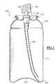
- the container 100 shown in Figure 1is in the form of a container, for aluminum example, comprising a body 101, one end 102 of which is closed by a bottom 103.
- the other end 104is open and is surmounted a valve 1 mounted on a cup 105, set on a rolled edge 106 of the can.
- the valve 1is crimped or clipped onto the cup 105.
- a push button 109is mounted on the valve so as to allow actuation of the valve 1, and the diffusion of the product via an outlet nozzle 107.
- a dip tube 108is connected to valve 1, and descends substantially to the bottom 103 of the container.
- the valvewill be the subject of a detailed description with reference to FIGS. 2A-2C and 3A-3C.
- the valve 1comprises mainly a body 2, the bottom 3 of which has an orifice 4 at its center surrounded by an axial chimney 7, arranged outside the valve body 2, and intended to receive a dip tube 108.
- the end of the valve body opposite the bottom 3,is open.
- the edge delimiting the opening 5 of the body of valve 2forms on its outer surface a bead 8 intended for attachment of valve 1 on a valve holder cup 105.
- Said edgealso forms inside the valve body 2, a recess intended to receive a seal seal 6.
- the seal 6is of annular shape, and forms in its center a opening, in which is slidably mounted a sealing rod valve 9.
- the valve stem 9comprises a first part 10, forming a passage for outlet of the product, in the form of a tubular element, and intended for mounting an actuation and distribution device (not shown), such as a pushbutton.
- the valve stem 9also includes a second part emerging 11, isolated from the first and intended for pressurization atmospheric, via an orifice 15, of a compartment 12 of a regulation 13.
- the orifice 15is made in the bottom 18 of the valve stem.
- AT inside the compartment 12 of the regulation chamber 13,is disposed a calibrated spring 14 intended to supply the regulation set point and which will be discussed in more detail later.
- the first part 10 of the valve stemcomprises a passage 17, passing radially through the tubular element.
- the regulation chamber 13is formed of a body 20, arranged coaxially inside the valve body 2, of which the upper end is closed by the bottom 18, and the lower end of which is closed by a bottom 21.
- a movable piston 22Inside the regulation chamber 13, is slidingly mounted a movable piston 22, sealingly isolating the upper compartment 12, and a lower compartment 23.
- a spring 14Inside the compartment 12 is arranged a spring 14 whose, the restoring force urges the movable piston 22 towards the bottom 21.
- the insulation between the compartment upper 12 and lower compartment 23is improved by the presence a thin membrane 24, in particular made of elastomeric material, and the peripheral edge is integral with the inner wall of the body of the chamber regulation.
- the pistonis isolated from the calibrated spring 14 by said membrane, preferably obtained by overmolding or bi-injection with the body of the regulation chamber.
- the bottom 21 of the regulation chamber 13is pierced in its center with an orifice 25 forming an inlet orifice for the regulation chamber.
- the body 20 of the regulation chamber 13is crossed, near the bottom 21, by an orifice 26 forming an outlet orifice for the regulation chamber 13.
- the piston 22is integral with a rod 27, arranged axially.
- the rod 27passes through the orifice 25, and has its free end ending by a plate 28 with an outside diameter greater than the diameter of the orifice 25.
- the rod, for its parthas an outer section less than the section of the orifice 25, so as to allow the product to pass between the interior walls of the orifice 25 and the rod 27.
- the rod 27is of sufficient length to be able to go from the closed position of the inlet port shown in the figure 2C, in the closed position of the outlet orifice 26, shown in the figure 2A.
- a seal 31is placed around the rod 27, in contact with the plate 28, so as to seal the inlet orifice 25 of the regulation chamber 13, in the event of overpressure inside the regulation.
- the piston 22extends on the side opposite to the compartment 12 by a portion annular skirt 29, of decreasing thickness in the direction of the bottom 21.
- the relative position of the skirt portion 29 relative to the orifice outlet 26,changes, so as to more or less clear the outlet orifice 26, and regulating the product outlet flow rate through the orifice 26.
- a sealingis carried out all around the regulation chamber, between the body 20 of the regulation chamber 13 and the internal wall of the valve body 2 at by means of a sealing lip 30, advantageously obtained by molding with the body 20 of the regulation chamber 13, and located near the bottom 21 of the regulation chamber 13, below the outlet orifice 26.
- valve stem 9is actuated, that is to say pressed in against the return force of the spring 16, which causes the release the outlet passage 17.
- the pressure inside the compartment 23is substantially equal to the pressure exerted by the spring calibrated 14.
- the piston 22is in an equilibrium position such that the inlet orifice 25 is not blocked by the plate 28.
- the skirt portion 29is above the orifice 26, which is entirely free.
- the productenters the regulation by the orifice 25, leaves the regulation chamber by the orifice 26, and is routed in the tubular part 10 of the valve stem 9, via the passage of exit 17.
- calibrated spring 14is chosen so as to allow optimal distribution of the product and a cessation of distribution as soon as the product can no longer be dispensed or sprayed under acceptable conditions due to pressure too weak.
- FIGS. 2A-2Cillustrate a variant of the embodiment of FIGS. 2A-2C.
- the regulation chamber 13does not have any means for closing the inlet orifice.
- the closing means of the outlet orificeconsist of a skirt portion 29, integral with the piston 22, and having an orifice 40 whose position by with respect to the outlet 26 determines the output flow of the product.
- stop means 41are provided for so as to limit the ascent of the piston in the regulation chamber, in order to never completely block the outlet in the event of overpressure in the regulation chamber.
- valve stemis actuated, that is to say pressed against of the return force of the spring 16, which causes the passage to be cleared outlet 17.
- the pressure inside the compartment 23is substantially equal to the pressure exerted by the calibrated spring 14.
- the piston 22is in an equilibrium position such that port 40 is substantially in alignment with the outlet orifice 26.
- the productenters the regulation chamber through port 25, exits regulation chamber through the orifice 26, and is conveyed in the tubular part 10 of the valve stem 9, via the exit passage 17.
- the orifice 40 of the skirt 29is no longer opposite the outlet orifice 26, which is completely closed by the skirt 29 (see FIG. 3A), which interrupts definitively product distribution.
- the force of the calibrated spring 14is chosen so as to allow an optimal distribution of the product, and a stop of the distribution as soon as the product can no longer be distributed or sprayed in acceptable conditions, due to too low pressure.
Landscapes
- Chemical & Material Sciences (AREA)
- Dispersion Chemistry (AREA)
- Engineering & Computer Science (AREA)
- Mechanical Engineering (AREA)
- Containers And Packaging Bodies Having A Special Means To Remove Contents (AREA)
- Nozzles (AREA)
Description
Translated fromFrenchLa présente invention a trait à une valve selon le préambule de la revendication 1, notamment pour récipient aérosol,destiné à distribuer un produit, notamment cosmétique, selon un débitsensiblement constant. L'invention est tout particulièrement adaptée à ladistribution de déodorants, ou de produits de coiffage, notamment des laquesou des mousses.The present invention relates to a valve according to the preamble of
Dans le domaine des aérosols, se pose aujourd'hui le problème des variationsde performance entre le début d'utilisation du contenu du récipient, et la find'utilisation. Ces problèmes se posent en particulier pour les dispositifs, où lapressurisation du produit est réalisée au moyen d'un gaz comprimé, notammentdu dioxyde de carbone ou du dioxyde d'azote. Pour ces dispositifs, le gaz estsoit directement au contact du produit, soit isolé du produit par un piston ou unepoche contenant le produit. Les variations de débit et/ou de pression sont liéesdirectement aux chutes de pression à l'intérieur du récipient, lesquellesprovoquent inévitablement une chute du débit de sortie du produit.In the field of aerosols, the problem of variations arises todayof performance between the start of use of the contents of the container, and the enduse. These problems arise in particular for devices, where thepressurization of the product is carried out by means of a compressed gas, in particularcarbon dioxide or nitrogen dioxide. For these devices, the gas iseither directly in contact with the product, or isolated from the product by a piston or apocket containing the product. Flow and / or pressure variations are linkeddirectly to pressure drops inside the container, whichinevitably cause a drop in the product outlet flow.
Il est connu, notamment de la demande de brevet EP-A-0 450 990 de prévoirune régulation à l'intérieur d'une valve de manière à réguler le débit de sortiedu produit distribué. De tels systèmes de régulation impliquent entre autres,l'utilisation d'un ressort taré, commandant l'ouverture plus ou moins grande oula fermeture d'un orifice, en fonction de la pression à l'intérieur de la chambrede régulation, par rapport à la pression de consigne imposée par le ressort. Eneffet, une surpression dans la chambre de régulation provoque une fermeturede l'orifice d'entrée de la chambre de régulation, jusqu'à ce que, aprèsévacuation d'une quantité suffisante de produit contenu dans la chambre derégulation, la pression dans la chambre revienne à la pression nominale. Undes inconvénients liés à un tel système de régulation tient au fait que le ressorttaré est disposé dans une partie du corps de valve, en communication avec leproduit. La pression régnant dans cette partie du corps de valve est une pression partielle entre la pression atmosphérique et la pression à l'intérieur durécipient. Une telle pression dépend de la pression interne du récipient, et despertes de charge existant jusqu'à l'orifice de sortie du produit. La pressiondépend également du produit contenu dans le récipient, en particulier de satension de vapeur. Ainsi, pour chaque nouvelle formule, il est nécessaired'utiliser un ressort taré différent, ce qui rend le système peu flexible. En outre,les moyens d'obturation de l'orifice de sortie ne sont pas solidaires du piston, cequi rend moins précise la régulation de débit obtenue.It is known, in particular from patent application EP-A-0 450 990 to provideregulation inside a valve so as to regulate the outlet flowof the product distributed. Among other things, such regulatory systems involvethe use of a calibrated spring, controlling the opening more or less large orthe closing of an orifice, depending on the pressure inside the chamberregulation, relative to the set pressure imposed by the spring. Inoverpressure in the control chamber causes closurefrom the inlet of the control chamber, until afterevacuation of a sufficient quantity of product contained in theregulation, the pressure in the chamber returns to the nominal pressure. Adrawbacks linked to such a regulation system is due to the fact that the springcalibrated is placed in a part of the valve body, in communication with theproduct. The pressure in this part of the valve body is apartial pressure between atmospheric pressure and the pressure inside thecontainer. Such a pressure depends on the internal pressure of the container, and thepressure losses existing up to the product outlet. Pressurealso depends on the product in the container, especially itsvapor pressure. So, for each new formula, it is necessaryto use a different calibrated spring, which makes the system not very flexible. In addition,the means for closing the outlet orifice are not integral with the piston, thiswhich makes the flow regulation obtained less precise.
La demande de brevet FR 2 711 973 décrit un bouton poussoir à l'intérieurduquel est disposé un système de régulation. Les inconvénients d'un telsystème sont principalement de deux ordres. D'une part, le système derégulation occupe une place substantielle dans le bouton poussoir, ce quilaisse peu de liberté au niveau de la définition de l'alimentation de la buse desortie ou du système de diffusion et du mécanisme de pulvérisation. D'autrepart, les moyens d'obturation de la chambre de régulation sont, entre deuxutilisations, en communication avec l'extérieur du récipient, et donc avec l'air,ce qui implique une risque de "collage" élevé de l'obturateur, notamment dansle cas de produits à forte teneur en résine.
Aussi, est-ce un des objets de l'invention que de réaliser une valve à régulationde débit ne présentant pas les inconvénients relatifs aux dispositifs derégulation discutés précédemment en référence aux dispositifs de la techniqueantérieure.It is therefore one of the objects of the invention to provide a regulating valveflow without the drawbacks relating to theregulation previously discussed with reference to the devices of the techniqueearlier.
C'est en particulier un objet de l'invention que de fournir une valve à dispositifde régulation intégré, fiable et économique à réaliser, et en particulier dont laconsigne ne varie pas en fonction du produit à distribuer, ou des variations depression à l'intérieur du récipient sur laquelle elle est destinée à être montée.It is in particular an object of the invention to provide a device valveintegrated regulation, reliable and economical to perform, and in particular thedeposit does not vary depending on the product to be distributed, or variations inpressure inside the container on which it is intended to be mounted.
C'est un autre objet de l'invention que de fournir une valve sur laquelle on peutadapter n'importe quel type de tête de distribution, et autorisant une grandelatitude dans le choix des caractéristiques de diffusion de ladite tête.It is another object of the invention to provide a valve on which one canadapt any type of distribution head, and allowing a largelatitude in the choice of the diffusion characteristics of said head.
D'autres objets encore apparaítront de manière détaillée dans la description quisuit.Still other objects will appear in detail in the description whichfollows.
Selon l'invention, ces objets sont atteints en réalisant une valve, en particulierpour récipient aérosol, comprenant à l'intérieur d'un corps de valve : a) unpassage d'entrée en communication avec le récipient et un passage de sortie;b) des moyens pour, en réponse à une commande d'actionnement, mettre lepassage de sortie en communication avec le passage d'entrée; c) des premiermoyens de rappel élastiques pour solliciter la valve en position fermée; et d)des moyens de régulation de débit de sortie du produit, comprenant dessecond moyens de rappel élastiques pour fournir une pression de consignepour lesdits moyens de régulation, les second moyens de rappel élastiques (14) sont isolé du produit, la pression à l'intérieur dudit compartiment étant égale à lapression atmosphérique, caracterisée en ce que les second moyensde rappel élastiques sont disposés dans un compartiment du corps de valve.According to the invention, these objects are achieved by producing a valve, in particularfor an aerosol container, comprising inside a valve body: a) ainlet passage in communication with the container and an outlet passage;b) means for, in response to an actuation command, putting theexit passage in communication with the entry passage; c) firstelastic return means for biasing the valve in the closed position; and D)means for regulating the output flow rate of the product, comprisingsecond elastic return means for supplying a set pressurefor said regulation means, the second elastic return means (14) are isolated from the product, the pressure inside said compartment being equal to theatmospheric pressure, characterized in that the second meanselastic return are arranged in a compartment of the valve body.
Ainsi, les moyens de rappel élastiques étant à la pression atmosphérique, laconsigne qu'il impose est constante, quelle que soit la formule, et quelle quesoit la pression à l'intérieur du récipient. En outre les moyens d'obturationassociés au système de régulation étant situés à l'intérieur du corps de valve,c'est à dire isolés de l'extérieur en position de fermeture de la valve, il ne seproduit aucun phénomène de collage ou d'encrassement du mécanisme derégulation, lequel reste fiable avec le temps.Thus, the elastic return means being at atmospheric pressure, thesetpoint it imposes is constant, whatever the formula, and whateveror the pressure inside the container. In addition the sealing meansassociated with the regulation system being located inside the valve body,i.e. isolated from the outside in the valve closed position, it does notproduces no phenomenon of sticking or fouling of theregulation, which remains reliable over time.
Avantageusement, les moyens de régulation de débit comprennent unechambre de régulation, disposée entre le passage d'entrée et le passage desortie, ladite chambre de régulation comportant un orifice d'entrée et un orificede sortie, des moyens d'obturation, montés sur lesdits second moyens de rappel élastiques étant prévus pour, en fonction de la pression à l'intérieur de lachambre de régulation (en réalité, à l'intérieur de la partie dans laquelle circulele produit), modifier le degré d'ouverture de l'orifice d'entrée et/ou de sortie,lesdits second moyens de rappel élastiques étant disposés dans uncompartiment de la chambre de régulation, isolé du produit par un pistonmobile, en communication directe avec l'extérieur, et donc maintenu à lapression atmosphérique. Ainsi, même en cas de diffusion parasite par ouautour du piston, la pression à l'intérieur du compartiment contenant le ressorttaré, reste identique à la pression atmosphérique.Advantageously, the flow regulation means comprise aregulation chamber, arranged between the inlet passage and the passage ofoutlet, said control chamber having an inlet port and an orificeoutlet, shutter means, mounted on said second meanselastic return being provided for, depending on the pressure inside theregulation chamber (in reality, inside the part in which circulatesthe product), modify the degree of opening of the inlet and / or outlet orifice,said second elastic return means being arranged in aregulation chamber compartment, isolated from the product by a pistonmobile, in direct communication with the outside, and therefore maintained atatmospheric pressure. Thus, even in the event of parasitic diffusion by oraround the piston, the pressure inside the compartment containing the springtared, remains identical to atmospheric pressure.
Avantageusement, le piston mobile est solidaire desdits premier moyensd'obturation. Ceci contribue à améliorer la précision de la régulation dans ledébit de sortie du produit.Advantageously, the movable piston is integral with said first meansshutter. This contributes to improving the precision of the regulation in theproduct outlet flow.
Selon un mode de réalisation spécifique, les moyens d'obturation comprennentdes premier moyens d'obturation de l'orifice de sortie, constitués d'une jupeannulaire portée par le piston et disposée à l'intérieur de la chambre derégulation, et dont la position par rapport à l'orifice de sortie détermine le degréd'ouverture de ce dernier. La jupe annulaire forme une seule pièce avec lepiston, pouvant être obtenue de moulage d'un matériau thermoplastique, tellequ'une polyoléfine, notamment un polyéthylène ou un polypropylène.According to a specific embodiment, the sealing means comprisefirst means for closing the outlet orifice, consisting of a skirtannular carried by the piston and disposed inside the chamberregulation, and whose position relative to the outlet orifice determines the degreeopening of the latter. The annular skirt forms a single piece with thepiston, obtainable by molding a thermoplastic material, suchthan a polyolefin, in particular a polyethylene or a polypropylene.
Avantageusement, le piston mobile est monté coulissant à l'intérieur de lachambre de régulation. L'étanchéité entre le compartiment contenant le ressorttaré et le compartiment formant la chambre de régulation proprement dite, estaméliorée au moyen d'une membrane souple disposée à l'intérieur du corps dela chambre de régulation, entre le piston et le ressort taré. De préférence, unetelle membrane est surmoulée ou bi-injectée avec le corps de la chambre derégulation. Cette membrane parfait l'étanchéité entre les deux compartimentsde la chambre de régulation, sans affecter de manière sensible la force d'appuiexercée par les second moyens de rappel élastiques sur le piston.Advantageously, the movable piston is slidably mounted inside theregulation chamber. The seal between the compartment containing the springcalibrated and the compartment forming the actual regulation chamber isimproved by means of a flexible membrane arranged inside the body ofthe regulation chamber, between the piston and the calibrated spring. Preferably, asuch a membrane is overmolded or bi-injected with the body of theregulation. This membrane completes the seal between the two compartmentsof the regulation chamber, without appreciably affecting the pressing forceexerted by the second elastic return means on the piston.
Avantageusement encore, des moyens de butée sont prévus pour, en cas desurpression à l'intérieur de la chambre de régulation, maintenir un débitminimum de sortie du produit. On permet ainsi la sortie du produit contenu dansla chambre de régulation, jusqu'à ce que la pression à l'intérieur de la chambrede régulation revienne au niveau de la consigne imposée par les secondmoyens de rappel élastiques, évitant ainsi tout phénomène de blocage de lavalve.Advantageously also, stop means are provided for, in the event ofoverpressure inside the regulation chamber, maintain a flowminimum product output. This allows the product contained inthe regulation chamber, until the pressure inside the chamberreturns to the level set by the secondelastic return means, thus avoiding any phenomenon of blockage of thevalve.
Les moyens d'obturation peuvent également comprendre des second moyensd'obturation, solidaires du piston mobile pour, en fonction de la pression àl'intérieur de la chambre de régulation, modifier le degré d'ouverture de l'orificed'entrée de la chambre de régulation, lesdits premier et second moyensd'obturation étant agencés de sorte qu'en position fermée de l'orifice d'entrée,l'orifice de sortie soit au moins partiellement ouvert. On améliore encore leniveau de régulation de la valve. En effet, selon ce mode de réalisation, onrégule également la pression à l'intérieur de la chambre de régulation.The sealing means may also include second meansshutter, integral with the movable piston for, depending on the pressure atinside the regulation chamber, modify the degree of opening of the orificeof the regulation chamber, said first and second meansshutter being arranged so that in the closed position of the inlet orifice,the outlet is at least partially open. We further improve thevalve regulation level. Indeed, according to this embodiment, wealso regulates the pressure inside the regulation chamber.
Selon un mode de réalisation particulier, l'orifice d'entrée est disposé dans lefond de la chambre de régulation, l'orifice de sortie étant situé sur une paroilatérale de la chambre de régulation, à distance d du fond de la chambre derégulation, une lèvre annulaire assurant l'étanchéité entre la chambre derégulation et le corps de valve, tout autour de ladite chambre de régulation,ladite lèvre d'étanchéité étant disposée axialement entre le fond de la chambrede régulation et l'orifice de sortie. Une telle lèvre annulaire peut être obtenuede moulage avec la chambre de régulation.According to a particular embodiment, the inlet orifice is arranged in thebottom of the regulation chamber, the outlet orifice being located on a wallside of the control chamber, at a distance d from the bottom of the control chamberregulation, an annular lip ensuring sealing between theregulation and the valve body, all around said regulation chamber,said sealing lip being disposed axially between the bottom of the chamberregulator and outlet. Such an annular lip can be obtainedmolding with the regulation chamber.
Selon un mode de réalisation préféré, le passage de sortie est formé d'une tigede valve solidaire de la chambre de régulation, ladite chambre de régulationétant montée sur lesdits premier moyens de rappel élastiques, ladite tige devalve comportant une partie émergente hors du corps de valve, et formant uncanal de sortie pouvant être mis en communication avec le corps de valve viaun passage traversant radialement la tige de valve. Alternativement, il peut s'agir d'une valve de type "femelle" destinée à recevoir une tige creuse portéepar le mécanisme d'actionnement de la valve.According to a preferred embodiment, the outlet passage is formed of a rodvalve integral with the regulation chamber, said regulation chamberbeing mounted on said first elastic return means, said rodvalve comprising an emerging part outside the valve body, and forming aoutlet channel which can be put in communication with the valve body viaa passage passing radially through the valve stem. Alternatively, it canbe a "female" type valve intended to receive a hollow hollow rodby the valve actuation mechanism.
Avantageusement, en position fermée de la valve, le passage radial estmaintenu en regard d'un joint d'étanchéité situé dans la partie supérieure ducorps de valve.Advantageously, in the closed position of the valve, the radial passage ismaintained opposite a seal located in the upper part of thevalve body.
Selon un autre mode de réalisation préférentiel, lorsque la pression à l'intérieurde la chambre de régulation descend sous une valeur prédéterminée, lesmoyens d'obturation obturent de manière étanche l'orifice de sortie de lachambre de régulation, de manière à interrompre la distribution de produit.Ainsi, on empêche toute pulvérisation ou diffusion dont les caractéristiques neseraient pas satisfaisantes, en raison d'une pression de sortie insuffisante.According to another preferred embodiment, when the pressure insideof the regulation chamber drops below a predetermined value, thesealing means seal the outlet orifice of theregulation chamber, so as to interrupt the dispensing of product.This prevents any spraying or diffusion whose characteristics do notwould be unsatisfactory due to insufficient outlet pressure.
Selon un autre aspect de l'invention, on réalise également un récipient pour ladistribution sous pression d'un produit, équipé d'une valve conforme àl'invention.According to another aspect of the invention, a container is also produced for thepressure distribution of a product, fitted with a valve conforming tothe invention.
Un tel récipient peut comprendre un corps définissant un réservoir contenant leproduit à distribuer, et dont une extrémité est fermée par un fond, l'autreextrémité étant surmontée de ladite valve, le moyen d'actionnement de la valveétant constitué d'un bouton poussoir pouvant présenter des moyens dediffusion pour la sortie du produit. Un tel récipient peut se présenter notammentsous forme d'une poche souple, placée éventuellement à l'intérieur d'un corpsrigide, d'un tube, ou d'un bidon.Such a container may comprise a body defining a reservoir containing theproduct to be dispensed, one end of which is closed by a bottom, the otherend being surmounted by said valve, the means for actuating the valveconsisting of a push button which may have means ofbroadcast for product release. Such a container can be presented in particularin the form of a flexible pocket, possibly placed inside a bodyrigid, a tube, or a can.
A titre d'exemple, les moyens de diffusion sont constitués d'une buse,notamment tourbillonnaire, d'une grille, ou d'un embout poreux, notamment unfritté ou une mousse à cellules ouvertes. Le produit peut être constitué d'unproduit de coiffage, notamment une laque, un spray ou une mousse, ou undéodorant, ou un produit de soin, notamment un lait, une huile, une crème ouun gel.By way of example, the diffusion means consist of a nozzle,in particular vortex, a grid, or a porous tip, in particular asintered or open cell foam. The product can consist of astyling product, in particular a hairspray, a spray or a mousse, or adeodorant, or a care product, in particular a milk, an oil, a cream ora gel.
L'invention consiste, mises à part les dispositions exposées ci-dessus, en uncertain nombre d'autres dispositions qui seront explicitées ci-après, à proposd'exemples de réalisation non limitatifs, décrits en référence aux figuresannexées, parmi lesquelles :
- le figure 1 représente un mode de réalisation d'un récipient équipé d'unevalve selon l'invention;
- les figures 2A-2C illustrent de façon schématique un premier mode deréalisation d'une valve selon l'invention; et
- les figures 3A-3C illustrent de façon schématique un second mode deréalisation d'une valve selon l'invention.
- FIG. 1 represents an embodiment of a container equipped with a valve according to the invention;
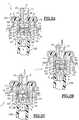
- FIGS. 2A-2C schematically illustrate a first embodiment of a valve according to the invention; and
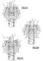
- Figures 3A-3C schematically illustrate a second embodiment of a valve according to the invention.
Le récipient 100 représenté à la figure 1 est sous forme d'un bidon, parexemple en aluminium, comprenant un corps 101 dont une extrémité 102 estfermée par un fond 103. L'autre extrémité 104 est ouverte et est surmontéed'une valve 1 montée sur une coupelle 105, sertie sur un bord roulé 106 dubidon. La valve 1 est sertie ou clipsée sur la coupelle 105. Un bouton poussoir109 est monté sur la valve de manière à permettre l'actionnement de la valve 1,et la diffusion du produit via une buse de sortie 107. Un tube plongeur 108 estrelié à la valve 1, et descend sensiblement jusqu'au fond 103 du bidon. Lavalve fera l'objet d'une description détaillée en référence aux figures 2A-2C et3A-3C.The
Dans le mode de réalisation des figures 2A-2C, la valve 1 comprendprincipalement un corps 2 dont le fond 3 présente en son centre un orifice 4entouré d'une cheminée axiale 7, disposée à l'extérieur du corps de valve 2, etdestinée à recevoir un tube plongeur 108. L'extrémité du corps de valveopposée au fond 3, est ouverte. Le bord délimitant l'ouverture 5 du corps devalve 2 forme sur sa surface extérieure un bourrelet 8 destiné à l'accrochagede la valve 1 sur une coupelle porte valve 105. Ledit bord forme également àl'intérieur du corps de valve 2, un décrochement destiné à recevoir un jointd'étanchéité 6. Le joint 6 est de forme annulaire, et forme en son centre une ouverture, dans laquelle est montée à coulisse, de manière étanche une tige devalve 9.In the embodiment of FIGS. 2A-2C, the
La tige de valve 9 comprend une première partie 10, formant un passage desortie du produit, sous forme d'un élément tubulaire, et destinée au montaged'un dispositif d'actionnement et de distribution (non représenté), tel qu'unbouton poussoir. La tige de valve 9 comprend également une seconde partieémergente 11, isolée de la première et destinée à la mise à la pressionatmosphérique, via un orifice 15, d'un compartiment 12 d'une chambre derégulation 13. L'orifice 15 est réalisé dans le fond 18 de la tige de valve. Al'intérieur du compartiment 12 de la chambre de régulation 13, est disposé unressort taré 14 destiné à fournir la consigne de régulation et dont on parleraplus en détail par la suite. La première partie 10 de la tige de valve comporteun passage 17, traversant radialement l'élément tubulaire. En position de reposde la valve (figure 1A), sous l'action de rappel élastique exercée par le ressort16, le passage 17 est disposé en regard du joint annulaire 6, de manière àmaintenir la valve en position de fermeture. A cet effet, le ressort 16 est enappui d'une part contre le fond 21 de la chambre de régulation, et d'autre partcontre le fond 3 du corps de valve. Le fond 18 de la tige de valve présente unearête annulaire 19, tournée vers le joint 6, et qui, sous l'action du ressort 16, estmaintenue en appui sur le joint d'étanchéité 6, tout autour de la tige de valve 9,de manière à assurer l'étanchéité à la fermeture.The
Du côté opposé à la tige de valve, le fond 18 est solidaire de la chambre derégulation 13, laquelle est de diamètre extérieur sensiblement identique audiamètre extérieur du fond 18. La chambre de régulation 13 est formée d'uncorps 20, disposé de manière coaxiale à l'intérieur du corps de valve 2, dontl'extrémité supérieure est fermée par le fond 18, et dont l'extrémité inférieureest fermée par un fond 21. A l'intérieur de la chambre de régulation 13, estmonté à coulisse un piston mobile 22, isolant de manière étanche lecompartiment supérieur 12, et un compartiment inférieur 23. A l'intérieur ducompartiment 12 est disposé un ressort 14 dont, la force de rappel sollicite le piston mobile 22 en direction du fond 21. L'isolation entre le compartimentsupérieur 12 et le compartiment inférieur 23 est améliorée par la présenced'une fine membrane 24, notamment en matériau élastomérique, et dont lebord périphérique est solidaire de la paroi intérieure du corps de la chambre derégulation. Ainsi, le piston est isolé du ressort taré 14 par ladite membrane,obtenue de préférence, par surmoulage ou bi-injection avec le corps de lachambre de régulation.On the side opposite the valve stem, the bottom 18 is integral with the
Le fond 21 de la chambre de régulation 13 est percé en son centre d'un orifice25 formant un orifice d'entrée pour la chambre de régulation. Le corps 20 de lachambre de régulation 13 est traversé, au voisinage du fond 21, par un orifice26 formant un orifice de sortie pour la chambre de régulation 13. Du côtéopposé au compartiment 12, le piston 22 est solidaire d'une tige 27, disposéeaxialement. La tige 27 traverse l'orifice 25, et a son extrémité libre se terminantpar un plateau 28 de diamètre extérieur supérieur au diamètre de l'orifice 25.La tige quant à elle, est de section extérieure inférieure à la section de l'orifice25, de manière à permettre au produit de passer entre les parois intérieures del'orifice 25 et la tige 27. La tige 27 est de longueur suffisante pour pouvoirpasser de la position de fermeture de l'orifice d'entrée représentée à la figure2C, à la position de fermeture de l'orifice de sortie 26, représentée à la figure2A. Un joint 31 est disposé autour de la tige 27, en contact avec le plateau 28,de manière à assurer la fermeture étanche de l'orifice d'entrée 25 de lachambre de régulation 13, en cas de surpression à l'intérieur de la chambre derégulation.The bottom 21 of the
Le piston 22 se prolonge du côté opposé au compartiment 12 par une portionde jupe annulaire 29, d'épaisseur décroissante en direction du fond 21. Ainsi,en fonction de la pression à l'intérieur du récipient, comparée à la pression duressort taré 14, la position relative de la portion de jupe 29 par rapport à l'orificede sortie 26, change, de manière à dégager plus ou moins l'orifice de sortie 26,et à réguler le débit de sortie de produit au travers de l'orifice 26. Uneétanchéité est réalisée tout autour de la chambre de régulation, entre le corps 20 de la chambre de régulation 13 et la paroi interne du corps de valve 2 aumoyen d'une lèvre d'étanchéité 30, obtenue avantageusement de moulageavec le corps 20 de la chambre de régulation 13, et située au voisinage du fond21 de la chambre de régulation 13, en dessous de l'orifice de sortie 26.The
Le fonctionnement d'une telle régulation est le suivant. A la figure 2A, enposition non montée de la valve, ou dans le cas d'une valve montée sur unrécipient non encore rempli ou pratiquement vide, le ressort taré 14 sollicite lepiston 22, au travers de la membrane 24, en direction du fond 21 de lachambre de régulation, et la jupe 29 obture totalement l'orifice de sortie 26.Dans cette position, la tige de valve n'est pas actionnée. Le passage de sortie17 est situé en regard du joint 6.The operation of such regulation is as follows. In Figure 2A, invalve not mounted position, or in the case of a valve mounted on acontainer not yet filled or practically empty, the calibrated
A la figure 2B, la tige de valve 9 est actionnée, c'est à dire enfoncée àl'encontre de la force de rappel du ressort 16, ce qui provoque le dégagementdu passage de sortie 17. Dans cette configuration, la pression à l'intérieur ducompartiment 23 est sensiblement égale à la pression exercée par le ressorttaré 14. Le piston 22 est dans une position d'équilibre telle, que l'orifice d'entrée25 n'est pas obturé par le plateau 28. La portion de jupe 29 est au dessus del'orifice 26, lequel est entièrement dégagé. Le produit entre dans la chambre derégulation par l'orifice 25, sort de la chambre de régulation par l'orifice 26, et estacheminé dans la partie tubulaire 10 de la tige de valve 9, via le passage desortie 17.In FIG. 2B, the
Lorsque la pression diminue à l'intérieur du compartiment 23, le piston 22redescend dans la chambre de régulation 13, réduisant ainsi la section ouvertede l'orifice de sortie, ce qui provoque la remontée de la pression dans laditechambre de régulation, jusqu'à ce qu'elle revienne à la pression normale defonctionnement. Lorsque la pression devient trop faible à l'intérieur du récipient,notamment en fin d'utilisation, l'orifice de sortie 26 est totalement obturé par lajupe 29, ce qui interrompt définitivement la distribution de produit. La force duressort taré 14 est choisie de façon à permettre une distribution optimale du produit et un arrêt de la distribution dès que le produit ne peut plus êtredistribué ou pulvérisé dans des conditions acceptables, du fait d'une pressiontrop faible.When the pressure decreases inside the
Dès que la pression devient trop élevée dans la chambre de régulation 13, lepiston 22 remonte dans la chambre de régulation. Cette remontée du piston 22tend à obturer l'orifice d'entrée 25 de la chambre de régulation au moyen duplateau 28. En position extrême représentée à la figure 2C, l'orifice d'entrée 25est obturé de manière étanche par le plateau 28. L'orifice de sortie 26 estouvert au maximum. Dès que la pression redescend dans le compartiment 23pour revenir à une pression de fonctionnement normal, l'orifice d'entrée 25s'ouvre à nouveau, et le produit entre dans le compartiment 23. Il s'en suit unéquilibre permanent entre l'entrée 25 et la sortie 26 de la chambre derégulation, et donc une régulation excellente de débit et/ou de pression desortie de produit distribué par la valve.As soon as the pressure becomes too high in the
Les figures 3A-3C auxquelles il est maintenant fait référence, illustrent unevariante du mode de réalisation des figures 2A-2C. Selon cette variante, seulele débit de sortie du produit est contrôlé, le compartiment 23 de la chambre derégulation 13 étant à la même pression que le récipient. A la différence dupremier mode de réalisation, la chambre de régulation 13 ne comporte pas demoyens d'obturation de l'orifice d'entrée. Selon ce mode de réalisation, lesmoyens d'obturation de l'orifice de sortie sont constitués d'une portion de jupe29, solidaire du piston 22, et présentant un orifice 40 dont la position parrapport à l'orifice de sortie 26 détermine le débit de sortie du produit. De plus,dans le compartiment 12, des moyens formant butée 41 sont prévus demanière à limiter la remontée du piston dans la chambre de régulation, afin dene jamais obturer complètement l'orifice de sortie en cas de surpression dansla chambre de régulation.Figures 3A-3C to which reference is now made illustrate avariant of the embodiment of FIGS. 2A-2C. According to this variant, onlythe output flow of the product is controlled,
Le fonctionnement d'une telle régulation est le suivant. A la figure 3A, enposition non montée de la valve, ou dans le cas d'une valve montée sur un récipient non encore rempli, le ressort taré 14 sollicite le piston 22 en directiondu fond 21 de la chambre de régulation, et l'orifice 40 est décalé par rapport àl'orifice 26, de sorte que la jupe 29 obture totalement l'orifice de sortie 26. Danscette position, la tige de valve n'est pas actionnée. Le passage de sortie 17 estsitué en regard du joint 6.The operation of such regulation is as follows. In Figure 3A, invalve not mounted position, or in the case of a valve mounted on acontainer not yet filled, the calibrated
A la figure 3C, la tige de valve est actionnée, c'est à dire enfoncée à l'encontrede la force de rappel du ressort 16, ce qui provoque le dégagement du passagede sortie 17. Dans cette configuration, la pression à l'intérieur du compartiment23 est sensiblement égale à la pression exercée par le ressort taré 14. Lepiston 22 est dans une position d'équilibre telle, que l'orifice 40 estsensiblement en alignement avec l'orifice de sortie 26. Le produit entre dans lachambre de régulation par l'orifice 25, sort de la chambre de régulation parl'orifice 26, et est acheminé dans la partie tubulaire 10 de la tige de valve 9, viale passage de sortie 17.In FIG. 3C, the valve stem is actuated, that is to say pressed againstof the return force of the
Lorsque la pression devient trop faible à l'intérieur du récipient, notamment enfin d'utilisation, l'orifice 40 de la jupe 29 n'est plus en regard de l'orifice de sortie26, lequel est totalement obturé par la jupe 29 (voir figure 3A), ce qui interromptdéfinitivement la distribution de produit. La force du ressort taré 14 est choisiede façon à permettre une distribution optimale du produit, et un arrêt de ladistribution dès que le produit ne peut plus être distribué ou pulvérisé dans desconditions acceptables, du fait d'une pression trop faible.When the pressure becomes too low inside the container, especially inend of use, the
Dès que la pression devient trop élevée dans le compartiment 23 de lachambre de régulation 13, le piston 22 remonte dans la chambre de régulation.Cette remontée du piston 22 tend à obturer l'orifice de sortie 26 de la chambrede régulation, en décalant plus ou moins l'orifice 40 vers le haut, par rapport àl'orifice 26, réduisant ainsi le débit de sortie. En position extrême représentée àla figure 3B, le piston 22 est en butée contre la couronne annulaire 41. Danscette position, on conserve une ouverture minimale de l'orifice de sortie 26, demanière à ne pas bloquer la valve. Lorsque la pression revient à une pression normale de fonctionnement, le piston revient dans la position d'équilibre de lafigure 3C.As soon as the pressure becomes too high in
Dans la description détaillée qui précède, il a été fait référence à des modes deréalisation préférés de l'invention. Il est évident que des variantes peuvent yêtre apportées sans s'écarter de l'invention telle que revendiquée ci-après.A titre d'exemple, on peut, notamment dans le cas de formulesvisqueuses, s'affranchir de la présence de la membrane 24 au dessus dupiston 22. A titre d'exemple encore, la régulation peut ne se faire qu'en entréede la chambre de régulation, avec un dispositif à tige et plateau du type decelui décrit en référence aux figures 2A-2C.In the foregoing detailed description, reference has been made to modes ofpreferred embodiments of the invention. It is obvious that there are variationsbe made without departing from the invention as claimed below.By way of example, it is possible, in particular in the case of formulasviscous, overcome the presence of the
Claims (16)
- Valve (1), particularly for an aerosolcontainer, comprising, inside a valve body (2): a) aninlet passage (4) communicating with the inside of thecontainer and an outlet passage (10) communicating withthe outside; b) means (9) for, in response to anactuation command, placing the outlet passage (10) incommunication with the inlet passage (4); c) firstelastic return means (16) for urging the valve (1) intothe closed position; and d) means (12-14, 22, 25, 26,28, 29) of regulating the product outlet flow rate,comprising second elastic return means (14) forsupplying a datum pressure for the said regulatingmeans, the second elastic return means (14) beingarranged in a compartment (12) isolated from theproduct, the pressure inside the said compartment (12)being equal to atmospheric pressure,characterized inthat the compartment (12) is arranged inside the valvebody (2).
- Valve according to Claim 1,characterized in that the flow rate regulating means(12-14, 22, 25, 26, 28, 29) comprise a regulatingchamber (13) arranged between the inlet passage (4) andthe outlet passage (10), the said regulating chambercomprising an inlet orifice (25) and an outlet orifice(26), shut-off means (28, 29) mounted on the saidsecond elastic return means (14) being provided for,according to the pressure between the inlet orifice (25) and the outlet orifice (26), altering the extentto which the inlet orifice (25) and/or outlet orifice(26) is/are open, the said second elastic return means(14) being arranged in a compartment (12) of theregulating chamber (13) isolated from the product by amoving piston (22) and kept at atmospheric pressure.
- Valve according to Claim 2,characterized in that the moving piston (22) is securedto the said shut-off means (28, 29).
- Valve according to Claim 3,characterized in that the shut-off means (28, 29)comprise first means (29) of shutting off the outletorifice (26), these consisting of an annular skirt (29)borne by the piston (22) and arranged inside theregulating chamber (13), and whose position withrespect to the outlet orifice (26) determines theextent to which the latter is open.
- Valve according to any one of Claims 2to 4,characterized in that the moving piston (22) ismounted so that it can slide inside the regulatingchamber (13), a flexible diaphragm (24) being arrangedin the regulating chamber (13) between the said piston(22) and the second elastic return means (14) so as toisolate the piston (22) in a leaktight manner from thesaid second elastic return means (14).
- Valve according to Claim 5,characterized in that the flexible diaphragm (24) isovermoulded or twin-shot injection moulded with thebody of the regulating chamber (13).
- Valve according to any one of Claims 2to 6,characterized in that stop means (41) areprovided for, in the event of an overpressure insidethe regulating chamber (13), maintaining a minimumproduct outlet flow rate.
- Valve according to any one of Claims 2to 7,characterized in that the shut-off means (28, 29)additionally comprise second shut-off means (28)secured to the moving piston (22) for, according to thepressure inside the regulating chamber (13), altering the extent to which the inlet orifice (25) of theregulating chamber (13) is open, the said first andsecond shut-off means (28, 29) being configured suchthat when the inlet orifice (25) is in the closedposition, the outlet orifice (26) is at least partiallyopen.
- Valve according to any one of Claims 2to 8,characterized in that the inlet orifice (25) isarranged in the end wall (21) of the regulatingchamber, the outlet orifice (26) being situated in aside wall of the regulating chamber (13), a distance dfrom the end wall (21) of the regulating chamber, anannular lip (30) providing the seal between theregulating chamber (13) and the valve body (2), rightaround the said regulating chamber, the said sealinglip (30) being arranged axially between the end wall(21) of the regulating chamber and the outlet orifice(26).
- Valve according to any one of Claims 1to 9,characterized in that the outlet passage (10) isformed of a valve stem (9, 10) secured to theregulating chamber (13), the said regulating chamber(13) being mounted on the said first elastic returnmeans (16), the said valve stem (9, 10) comprising apart that emerges from the valve body and forms anoutlet duct that can be placed in communication withthe valve body via a passage (17) that passes radiallythrough the valve stem (9, 10).
- Valve according to Claim 10,characterized in that when the valve (1) is in theclosed position, the radial passage (17) is keptopposite a seal (6) located in the upper part of thevalve body (2).
- Valve according to any one of Claims 2to 11,characterized in that when the pressure insidethe regulating chamber (13) drops below a predeterminedvalue, the shut-off means (29) shut off the outletorifice (26) of the regulating chamber in a leaktightmanner so as to interrupt the dispensing of product.
- Container (100) for dispensing a productunder pressure, this container being equipped with avalve (1) according to any one of Claims 1 to 12.
- Container (100) according to Claim 13,characterized in that it comprises a body (101)defining a reservoir containing the product to bedispensed, and one end (102) of which is closed by anend wall (103), the other end (104) being surmounted bythe said valve (1), the means of actuating the valveconsisting of a push-button (109).
- Container according to Claim 14,characterized in that the push-button comprisesdiffuser means (107) for discharging the product, thediffuser means (107) consisting of a nozzle, especiallya swirl-inducing nozzle, a grating, or a porous endpiece, especially a sinter or an open-cell foam.
- Use of a container according to any oneof Claims 13 to 15 for packaging and dispensing underpressure a hairstyling product, especially a lacquer, aspray or a mousse, or a deodorant, or a beauty careproduct, especially a milk, an oil, a cream or a gel.
Applications Claiming Priority (2)
| Application Number | Priority Date | Filing Date | Title |
|---|---|---|---|
| FR9800720AFR2774077B1 (en) | 1998-01-23 | 1998-01-23 | VALVE WITH OUTLET FLOW REGULATION, AND CONTAINER PROVIDED WITH SUCH A VALVE |
| FR9800720 | 1998-01-23 |
Publications (2)
| Publication Number | Publication Date |
|---|---|
| EP0931734A1 EP0931734A1 (en) | 1999-07-28 |
| EP0931734B1true EP0931734B1 (en) | 2003-03-05 |
Family
ID=9522091
Family Applications (1)
| Application Number | Title | Priority Date | Filing Date |
|---|---|---|---|
| EP98403289AExpired - LifetimeEP0931734B1 (en) | 1998-01-23 | 1998-12-23 | Valve for regulating a fluid flow and container equipped with such a valve |
Country Status (7)
| Country | Link |
|---|---|
| US (2) | US6145712A (en) |
| EP (1) | EP0931734B1 (en) |
| JP (1) | JP3024112B2 (en) |
| CA (1) | CA2257485A1 (en) |
| DE (1) | DE69811848T2 (en) |
| ES (1) | ES2194292T3 (en) |
| FR (1) | FR2774077B1 (en) |
Families Citing this family (44)
| Publication number | Priority date | Publication date | Assignee | Title |
|---|---|---|---|---|
| NL1009292C1 (en) | 1998-05-29 | 1999-11-30 | Packaging Tech Holding Sa | Pressure control device for maintaining a constant predetermined pressure in a container. |
| NL1012754C2 (en) | 1999-07-30 | 2001-02-01 | Presstech N V | Pressure control device. |
| DE10029228A1 (en)* | 2000-06-14 | 2002-01-03 | Thomas Gmbh | Aerosol can with pressure reducing valve |
| JP2002331260A (en)* | 2001-05-10 | 2002-11-19 | Bioactis:Kk | Gas injection valve and injection jig used for gas injection |
| US6478199B1 (en)* | 2002-01-24 | 2002-11-12 | S. C. Johnson & Son, Inc. | Automatic valve |
| DE10229185A1 (en) | 2002-06-28 | 2004-02-05 | Thomas Gmbh | pressure regulating valve |
| US20040195375A1 (en)* | 2003-01-15 | 2004-10-07 | Richard Koeth | Systems and methods for application of tire treatment agent |
| NL1022455C2 (en)* | 2003-01-21 | 2004-07-22 | Packaging Tech Holding Sa | System for applying a working pressure to a content of a pressure package with the aid of a propellant. |
| NL1022456C2 (en)* | 2003-01-21 | 2004-07-22 | Packaging Tech Holding Sa | Pressure package system for applying a working pressure to a fluid contained in a pressure package. |
| WO2004108539A2 (en)* | 2003-06-05 | 2004-12-16 | Eliav Korakh | Liquid dispenser |
| DE20315714U1 (en)* | 2003-10-13 | 2003-12-18 | Lindal Ventil Gmbh | Tilting valve for the discharge of foam and other media |
| US7641080B2 (en)* | 2004-03-17 | 2010-01-05 | Pepsico., Inc. | Dispensing mechanism using long tubes to vary pressure drop |
| RU2363634C2 (en) | 2004-10-12 | 2009-08-10 | Эс.Си. Джонсон Энд Сан, Инк. | Compact sprayer |
| US8061562B2 (en) | 2004-10-12 | 2011-11-22 | S.C. Johnson & Son, Inc. | Compact spray device |
| FR2876809B1 (en)* | 2004-10-20 | 2009-06-26 | Global Business Strategy Ltd | DEVICE FOR CONTROLLING A GAS FLOW AND CONTAINING GAS EQUIPPED WITH SUCH A DEVICE |
| USD540194S1 (en) | 2006-02-16 | 2007-04-10 | Colgate-Palmolive Company | Container |
| EP1837082B1 (en)* | 2006-03-14 | 2012-08-29 | Packaging Technology Participation SA | Actuator for a receptacle having a pressurized content and method for spraying a pressurized content |
| EP1834701B1 (en)* | 2006-03-14 | 2010-12-29 | Packaging Technology Participation SA | Actuator for a receptacle having a pressurized content and method for spraying a pressurized content |
| FR2899210A1 (en) | 2006-03-30 | 2007-10-05 | Ad Venta Sarl | Pneumatic component for micro-diffusion of e.g. perfume, has fixation system forming intermediate chamber between piston and upper part of container, where body has orifice communicating with chamber when body is fixed on container |
| FR2903329B3 (en) | 2006-07-10 | 2008-10-03 | Rexam Dispensing Systems Sas | SPRAY NOZZLE, SPRAY DEVICE AND USE THEREOF. |
| US8590743B2 (en) | 2007-05-10 | 2013-11-26 | S.C. Johnson & Son, Inc. | Actuator cap for a spray device |
| US8556122B2 (en) | 2007-08-16 | 2013-10-15 | S.C. Johnson & Son, Inc. | Apparatus for control of a volatile material dispenser |
| US8381951B2 (en) | 2007-08-16 | 2013-02-26 | S.C. Johnson & Son, Inc. | Overcap for a spray device |
| US8469244B2 (en) | 2007-08-16 | 2013-06-25 | S.C. Johnson & Son, Inc. | Overcap and system for spraying a fluid |
| US8387827B2 (en) | 2008-03-24 | 2013-03-05 | S.C. Johnson & Son, Inc. | Volatile material dispenser |
| US20090283550A1 (en)* | 2008-05-16 | 2009-11-19 | Kimball James F | Extreme Barrier Metal Piston and Container Utilizing Same |
| US8245888B2 (en)* | 2008-10-24 | 2012-08-21 | S.C. Johnson & Son, Inc. | Barrier piston with seal |
| WO2011079219A1 (en)* | 2009-12-23 | 2011-06-30 | Summit Packaging Systems, Inc. | Pressure regulated flow valve with gas-piston |
| USD647407S1 (en) | 2010-11-05 | 2011-10-25 | Colgate-Palmolive Company | Container |
| USD667728S1 (en) | 2010-11-05 | 2012-09-25 | Colgate-Palmolive Company | Container |
| USD652318S1 (en) | 2010-11-05 | 2012-01-17 | Colgate-Palmolive Company | Container |
| USD667730S1 (en) | 2010-11-05 | 2012-09-25 | Colgate-Palmolive Company | Container |
| USD647806S1 (en) | 2010-11-05 | 2011-11-01 | Colgate-Palmolive Company | Container |
| JP5663417B2 (en)* | 2011-06-29 | 2015-02-04 | 株式会社吉野工業所 | Spray container |
| BR112015004185B1 (en) | 2012-09-14 | 2020-09-15 | The Procter & Gamble Company | ANTIPERSPIRANT COMPOSITIONS IN AEROSOL AND PRODUCTS |
| US9108782B2 (en) | 2012-10-15 | 2015-08-18 | S.C. Johnson & Son, Inc. | Dispensing systems with improved sensing capabilities |
| WO2014089358A1 (en)* | 2012-12-05 | 2014-06-12 | Pada Medical Products, Llc | Pressure and flow regulator for pressurized containers |
| CN103612835B (en)* | 2013-12-03 | 2015-09-09 | 北京北机机电工业有限责任公司 | Valve body structure and the powder bottle of this valve body structure is set |
| US9579265B2 (en) | 2014-03-13 | 2017-02-28 | The Procter & Gamble Company | Aerosol antiperspirant compositions, products and methods |
| US9662285B2 (en) | 2014-03-13 | 2017-05-30 | The Procter & Gamble Company | Aerosol antiperspirant compositions, products and methods |
| MX383959B (en)* | 2015-04-01 | 2025-03-14 | Graham Packaging Co | Structure and method of sealing a closure assembly onto the neck finish of a plastic pressure container |
| GB2579628B (en)* | 2018-12-07 | 2021-07-21 | Corplex Plastics Uk Ltd | Bag side connector for a BIB package |
| KR102534856B1 (en)* | 2020-06-24 | 2023-05-22 | 주식회사 인더케그 | Keg cap and keg having the same |
| JP2022111773A (en)* | 2021-01-20 | 2022-08-01 | 積水化学工業株式会社 | Two liquid aerosol injection device |
Family Cites Families (7)
| Publication number | Priority date | Publication date | Assignee | Title |
|---|---|---|---|---|
| US2618290A (en)* | 1949-09-22 | 1952-11-18 | Liquid Carbonic Corp | Throttling valve for refrigeration |
| US2781950A (en)* | 1953-01-08 | 1957-02-19 | Tanra Mfg Co | Dispensing valve |
| US3666148A (en)* | 1969-10-13 | 1972-05-30 | Gillette Co | Aerosol valve with safety relief device |
| US3913804A (en)* | 1974-07-19 | 1975-10-21 | Robert H Laauwe | Aerosol valve actuator |
| FR2559567B1 (en)* | 1984-02-10 | 1986-07-11 | Valois Sa | DOSING VALVE FOR CONTAINER CONTAINING A PRESSURIZED PRODUCT |
| FR2667673B2 (en) | 1990-04-03 | 1993-03-19 | Oreal | SELF-LOCKING VALVE, ESPECIALLY FOR AEROSOL CONTAINER. |
| US5415328A (en)* | 1993-02-18 | 1995-05-16 | Kyowa Industrial Co., Ltd. | Spray mechanism of aerosol product |
- 1998
- 1998-01-23FRFR9800720Apatent/FR2774077B1/ennot_activeExpired - Fee Related
- 1998-12-23ESES98403289Tpatent/ES2194292T3/ennot_activeExpired - Lifetime
- 1998-12-23EPEP98403289Apatent/EP0931734B1/ennot_activeExpired - Lifetime
- 1998-12-23DEDE69811848Tpatent/DE69811848T2/ennot_activeExpired - Fee Related
- 1999
- 1999-01-19CACA002257485Apatent/CA2257485A1/ennot_activeAbandoned
- 1999-01-20USUS09/233,064patent/US6145712A/ennot_activeCeased
- 1999-01-22JPJP11014831Apatent/JP3024112B2/ennot_activeExpired - Fee Related
- 2001
- 2001-04-03USUS09/824,036patent/USRE38207E1/ennot_activeExpired - Lifetime
Also Published As
| Publication number | Publication date |
|---|---|
| DE69811848T2 (en) | 2003-09-04 |
| CA2257485A1 (en) | 1999-07-23 |
| FR2774077A1 (en) | 1999-07-30 |
| EP0931734A1 (en) | 1999-07-28 |
| JP3024112B2 (en) | 2000-03-21 |
| US6145712A (en) | 2000-11-14 |
| DE69811848D1 (en) | 2003-04-10 |
| ES2194292T3 (en) | 2003-11-16 |
| JPH11263385A (en) | 1999-09-28 |
| USRE38207E1 (en) | 2003-08-05 |
| FR2774077B1 (en) | 2000-04-07 |
Similar Documents
| Publication | Publication Date | Title |
|---|---|---|
| EP0931734B1 (en) | Valve for regulating a fluid flow and container equipped with such a valve | |
| EP1156300B1 (en) | Dosing tip and a container with such a dosing tip | |
| CA2248232C (en) | Dispenser head with improved air intake, and packaging and distribution assembly fitted with such a head | |
| EP0906873B1 (en) | Packaging and dispensing unit for bi-products | |
| CA2136585C (en) | Liquid applicator | |
| EP0709305B1 (en) | Dispensing valve and dispenser provided with this valve | |
| EP1164362B1 (en) | Dosing tip for distributing a variable dose and a container with such a dosing tip | |
| EP0622124B1 (en) | Product dispensing assembly | |
| EP1572375B1 (en) | Manually-actuated metering pump | |
| EP1291293A1 (en) | Valve with variable discharge and container having such valve | |
| FR2792913A1 (en) | DEVICE FOR ACTUATING A DISPENSING MEMBER, PARTICULARLY A VALVE, AND ASSEMBLY EQUIPPED WITH THE OPERATING DEVICE ACCORDING TO THE INVENTION | |
| EP1035038A1 (en) | Unit for storing and dispensing a product under pressure, especially cosmetics | |
| EP0939039B1 (en) | Dispensing head for the dispensing of a material and assembly for dispensing under pressure equipped with such a head | |
| EP1284827A1 (en) | Diaphragm pump | |
| EP2005273B1 (en) | Pneumatic component for the controlled micro-diffusion of gas | |
| EP1302246B1 (en) | Device for spraying at least one product on a substrate, especially on a keratinous substrate such as skin | |
| FR2808258A1 (en) | AEROSOL CONTAINER WITH IMPROVED VALVE | |
| EP1535860B1 (en) | Variable-delivery tilt valve | |
| EP1400465B1 (en) | Variable-delivery tiilt valve as well as container having such valve | |
| CA1104530A (en) | Method for reducing flammability of the atomizing stream from a pressurized container | |
| EP1230031B1 (en) | Fast rate pump |
Legal Events
| Date | Code | Title | Description |
|---|---|---|---|
| PUAI | Public reference made under article 153(3) epc to a published international application that has entered the european phase | Free format text:ORIGINAL CODE: 0009012 | |
| AK | Designated contracting states | Kind code of ref document:A1 Designated state(s):DE ES FR GB IT | |
| AX | Request for extension of the european patent | Free format text:AL;LT;LV;MK;RO;SI | |
| 17P | Request for examination filed | Effective date:19990830 | |
| AKX | Designation fees paid | Free format text:DE ES FR GB IT | |
| 17Q | First examination report despatched | Effective date:20011217 | |
| GRAH | Despatch of communication of intention to grant a patent | Free format text:ORIGINAL CODE: EPIDOS IGRA | |
| GRAH | Despatch of communication of intention to grant a patent | Free format text:ORIGINAL CODE: EPIDOS IGRA | |
| GRAA | (expected) grant | Free format text:ORIGINAL CODE: 0009210 | |
| AK | Designated contracting states | Designated state(s):DE ES FR GB IT | |
| REG | Reference to a national code | Ref country code:GB Ref legal event code:FG4D Free format text:NOT ENGLISH | |
| REF | Corresponds to: | Ref document number:69811848 Country of ref document:DE Date of ref document:20030410 Kind code of ref document:P | |
| GBT | Gb: translation of ep patent filed (gb section 77(6)(a)/1977) | ||
| REG | Reference to a national code | Ref country code:ES Ref legal event code:FG2A Ref document number:2194292 Country of ref document:ES Kind code of ref document:T3 | |
| PGFP | Annual fee paid to national office [announced via postgrant information from national office to epo] | Ref country code:FR Payment date:20031210 Year of fee payment:6 | |
| PGFP | Annual fee paid to national office [announced via postgrant information from national office to epo] | Ref country code:GB Payment date:20031217 Year of fee payment:6 | |
| PGFP | Annual fee paid to national office [announced via postgrant information from national office to epo] | Ref country code:ES Payment date:20031230 Year of fee payment:6 | |
| PGFP | Annual fee paid to national office [announced via postgrant information from national office to epo] | Ref country code:DE Payment date:20040102 Year of fee payment:6 | |
| PLBE | No opposition filed within time limit | Free format text:ORIGINAL CODE: 0009261 | |
| STAA | Information on the status of an ep patent application or granted ep patent | Free format text:STATUS: NO OPPOSITION FILED WITHIN TIME LIMIT | |
| 26N | No opposition filed | Effective date:20031208 | |
| PG25 | Lapsed in a contracting state [announced via postgrant information from national office to epo] | Ref country code:GB Free format text:LAPSE BECAUSE OF NON-PAYMENT OF DUE FEES Effective date:20041223 | |
| PG25 | Lapsed in a contracting state [announced via postgrant information from national office to epo] | Ref country code:ES Free format text:LAPSE BECAUSE OF NON-PAYMENT OF DUE FEES Effective date:20041224 | |
| PG25 | Lapsed in a contracting state [announced via postgrant information from national office to epo] | Ref country code:DE Free format text:LAPSE BECAUSE OF NON-PAYMENT OF DUE FEES Effective date:20050701 | |
| GBPC | Gb: european patent ceased through non-payment of renewal fee | Effective date:20041223 | |
| PG25 | Lapsed in a contracting state [announced via postgrant information from national office to epo] | Ref country code:FR Free format text:LAPSE BECAUSE OF NON-PAYMENT OF DUE FEES Effective date:20050831 | |
| REG | Reference to a national code | Ref country code:FR Ref legal event code:ST | |
| PG25 | Lapsed in a contracting state [announced via postgrant information from national office to epo] | Ref country code:IT Free format text:LAPSE BECAUSE OF NON-PAYMENT OF DUE FEES Effective date:20051223 | |
| REG | Reference to a national code | Ref country code:ES Ref legal event code:FD2A Effective date:20041224 |