EP0931562B1 - Low profile dilatation catheter - Google Patents
Low profile dilatation catheterDownload PDFInfo
- Publication number
- EP0931562B1 EP0931562B1EP99106636AEP99106636AEP0931562B1EP 0931562 B1EP0931562 B1EP 0931562B1EP 99106636 AEP99106636 AEP 99106636AEP 99106636 AEP99106636 AEP 99106636AEP 0931562 B1EP0931562 B1EP 0931562B1
- Authority
- EP
- European Patent Office
- Prior art keywords
- tubular member
- catheter
- distal
- inner tubular
- outer tubular
- Prior art date
- Legal status (The legal status is an assumption and is not a legal conclusion. Google has not performed a legal analysis and makes no representation as to the accuracy of the status listed.)
- Expired - Lifetime
Links
- 230000010412perfusionEffects0.000claimsdescription18
- 238000004891communicationMethods0.000claimsdescription13
- 239000012530fluidSubstances0.000claimsdescription10
- 238000011282treatmentMethods0.000claimsdescription8
- 238000003780insertionMethods0.000claimsdescription2
- 230000037431insertionEffects0.000claimsdescription2
- 208000018672DilatationDiseases0.000description34
- 239000008280bloodSubstances0.000description9
- 210000004369bloodAnatomy0.000description9
- 230000003902lesionEffects0.000description9
- 238000000034methodMethods0.000description9
- 239000004033plasticSubstances0.000description9
- 229920003023plasticPolymers0.000description9
- 238000002399angioplastyMethods0.000description7
- 210000001367arteryAnatomy0.000description5
- 210000004351coronary vesselAnatomy0.000description5
- 208000031481Pathologic ConstrictionDiseases0.000description4
- 210000003484anatomyAnatomy0.000description4
- 230000000302ischemic effectEffects0.000description4
- 239000000463materialSubstances0.000description4
- 230000036262stenosisEffects0.000description4
- 208000037804stenosisDiseases0.000description4
- 229910045601alloyInorganic materials0.000description3
- 239000000956alloySubstances0.000description3
- 210000000748cardiovascular systemAnatomy0.000description3
- 238000012986modificationMethods0.000description3
- 230000004048modificationEffects0.000description3
- 229910001000nickel titaniumInorganic materials0.000description3
- -1polyethylenePolymers0.000description3
- 230000002966stenotic effectEffects0.000description3
- 239000004698PolyethyleneSubstances0.000description2
- 210000000709aortaAnatomy0.000description2
- 238000010276constructionMethods0.000description2
- 238000007887coronary angioplastyMethods0.000description2
- 238000003745diagnosisMethods0.000description2
- 230000002093peripheral effectEffects0.000description2
- 229920000573polyethylenePolymers0.000description2
- 230000009467reductionEffects0.000description2
- 239000010935stainless steelSubstances0.000description2
- 229910001220stainless steelInorganic materials0.000description2
- 210000005166vasculatureAnatomy0.000description2
- 239000004642PolyimideSubstances0.000description1
- 230000017531blood circulationEffects0.000description1
- 239000002131composite materialSubstances0.000description1
- 238000007796conventional methodMethods0.000description1
- 230000001419dependent effectEffects0.000description1
- 238000011161developmentMethods0.000description1
- 238000002405diagnostic procedureMethods0.000description1
- 230000009977dual effectEffects0.000description1
- 239000007788liquidSubstances0.000description1
- 230000007774longtermEffects0.000description1
- 229920000139polyethylene terephthalatePolymers0.000description1
- 239000005020polyethylene terephthalateSubstances0.000description1
- 229920001721polyimidePolymers0.000description1
- 229920000642polymerPolymers0.000description1
- 229920000915polyvinyl chloridePolymers0.000description1
- 239000004800polyvinyl chlorideSubstances0.000description1
- 238000004513sizingMethods0.000description1
- 230000001225therapeutic effectEffects0.000description1
- 238000002560therapeutic procedureMethods0.000description1
- 230000002792vascularEffects0.000description1
Images

Classifications
- A—HUMAN NECESSITIES
- A61—MEDICAL OR VETERINARY SCIENCE; HYGIENE
- A61M—DEVICES FOR INTRODUCING MEDIA INTO, OR ONTO, THE BODY; DEVICES FOR TRANSDUCING BODY MEDIA OR FOR TAKING MEDIA FROM THE BODY; DEVICES FOR PRODUCING OR ENDING SLEEP OR STUPOR
- A61M25/00—Catheters; Hollow probes
- A61M25/10—Balloon catheters
- A61M25/104—Balloon catheters used for angioplasty
- A—HUMAN NECESSITIES
- A61—MEDICAL OR VETERINARY SCIENCE; HYGIENE
- A61M—DEVICES FOR INTRODUCING MEDIA INTO, OR ONTO, THE BODY; DEVICES FOR TRANSDUCING BODY MEDIA OR FOR TAKING MEDIA FROM THE BODY; DEVICES FOR PRODUCING OR ENDING SLEEP OR STUPOR
- A61M25/00—Catheters; Hollow probes
- A61M25/0043—Catheters; Hollow probes characterised by structural features
- A—HUMAN NECESSITIES
- A61—MEDICAL OR VETERINARY SCIENCE; HYGIENE
- A61M—DEVICES FOR INTRODUCING MEDIA INTO, OR ONTO, THE BODY; DEVICES FOR TRANSDUCING BODY MEDIA OR FOR TAKING MEDIA FROM THE BODY; DEVICES FOR PRODUCING OR ENDING SLEEP OR STUPOR
- A61M25/00—Catheters; Hollow probes
- A61M2025/0004—Catheters; Hollow probes having two or more concentrically arranged tubes for forming a concentric catheter system
- A—HUMAN NECESSITIES
- A61—MEDICAL OR VETERINARY SCIENCE; HYGIENE
- A61M—DEVICES FOR INTRODUCING MEDIA INTO, OR ONTO, THE BODY; DEVICES FOR TRANSDUCING BODY MEDIA OR FOR TAKING MEDIA FROM THE BODY; DEVICES FOR PRODUCING OR ENDING SLEEP OR STUPOR
- A61M25/00—Catheters; Hollow probes
- A61M25/0021—Catheters; Hollow probes characterised by the form of the tubing
- A61M25/0023—Catheters; Hollow probes characterised by the form of the tubing by the form of the lumen, e.g. cross-section, variable diameter
- A61M25/0026—Multi-lumen catheters with stationary elements
- A61M2025/0034—Multi-lumen catheters with stationary elements characterized by elements which are assembled, connected or fused, e.g. splittable tubes, outer sheaths creating lumina or separate cores
- A—HUMAN NECESSITIES
- A61—MEDICAL OR VETERINARY SCIENCE; HYGIENE
- A61M—DEVICES FOR INTRODUCING MEDIA INTO, OR ONTO, THE BODY; DEVICES FOR TRANSDUCING BODY MEDIA OR FOR TAKING MEDIA FROM THE BODY; DEVICES FOR PRODUCING OR ENDING SLEEP OR STUPOR
- A61M25/00—Catheters; Hollow probes
- A61M25/0021—Catheters; Hollow probes characterised by the form of the tubing
- A61M25/0023—Catheters; Hollow probes characterised by the form of the tubing by the form of the lumen, e.g. cross-section, variable diameter
- A61M25/0026—Multi-lumen catheters with stationary elements
- A61M2025/0039—Multi-lumen catheters with stationary elements characterized by lumina being arranged coaxially
- A—HUMAN NECESSITIES
- A61—MEDICAL OR VETERINARY SCIENCE; HYGIENE
- A61M—DEVICES FOR INTRODUCING MEDIA INTO, OR ONTO, THE BODY; DEVICES FOR TRANSDUCING BODY MEDIA OR FOR TAKING MEDIA FROM THE BODY; DEVICES FOR PRODUCING OR ENDING SLEEP OR STUPOR
- A61M25/00—Catheters; Hollow probes
- A61M25/0043—Catheters; Hollow probes characterised by structural features
- A61M2025/0063—Catheters; Hollow probes characterised by structural features having means, e.g. stylets, mandrils, rods or wires to reinforce or adjust temporarily the stiffness, column strength or pushability of catheters which are already inserted into the human body
- A—HUMAN NECESSITIES
- A61—MEDICAL OR VETERINARY SCIENCE; HYGIENE
- A61M—DEVICES FOR INTRODUCING MEDIA INTO, OR ONTO, THE BODY; DEVICES FOR TRANSDUCING BODY MEDIA OR FOR TAKING MEDIA FROM THE BODY; DEVICES FOR PRODUCING OR ENDING SLEEP OR STUPOR
- A61M25/00—Catheters; Hollow probes
- A61M25/01—Introducing, guiding, advancing, emplacing or holding catheters
- A61M2025/0177—Introducing, guiding, advancing, emplacing or holding catheters having external means for receiving guide wires, wires or stiffening members, e.g. loops, clamps or lateral tubes
- A—HUMAN NECESSITIES
- A61—MEDICAL OR VETERINARY SCIENCE; HYGIENE
- A61M—DEVICES FOR INTRODUCING MEDIA INTO, OR ONTO, THE BODY; DEVICES FOR TRANSDUCING BODY MEDIA OR FOR TAKING MEDIA FROM THE BODY; DEVICES FOR PRODUCING OR ENDING SLEEP OR STUPOR
- A61M25/00—Catheters; Hollow probes
- A61M25/01—Introducing, guiding, advancing, emplacing or holding catheters
- A61M2025/0183—Rapid exchange or monorail catheters
- A—HUMAN NECESSITIES
- A61—MEDICAL OR VETERINARY SCIENCE; HYGIENE
- A61M—DEVICES FOR INTRODUCING MEDIA INTO, OR ONTO, THE BODY; DEVICES FOR TRANSDUCING BODY MEDIA OR FOR TAKING MEDIA FROM THE BODY; DEVICES FOR PRODUCING OR ENDING SLEEP OR STUPOR
- A61M25/00—Catheters; Hollow probes
- A61M25/10—Balloon catheters
- A61M2025/1043—Balloon catheters with special features or adapted for special applications
- A61M2025/1063—Balloon catheters with special features or adapted for special applications having only one lumen used for guide wire and inflation, e.g. to minimise the diameter
- A—HUMAN NECESSITIES
- A61—MEDICAL OR VETERINARY SCIENCE; HYGIENE
- A61M—DEVICES FOR INTRODUCING MEDIA INTO, OR ONTO, THE BODY; DEVICES FOR TRANSDUCING BODY MEDIA OR FOR TAKING MEDIA FROM THE BODY; DEVICES FOR PRODUCING OR ENDING SLEEP OR STUPOR
- A61M25/00—Catheters; Hollow probes
- A61M25/10—Balloon catheters
- A61M2025/1043—Balloon catheters with special features or adapted for special applications
- A61M2025/1097—Balloon catheters with special features or adapted for special applications with perfusion means for enabling blood circulation only while the balloon is in an inflated state, e.g. temporary by-pass within balloon
- A—HUMAN NECESSITIES
- A61—MEDICAL OR VETERINARY SCIENCE; HYGIENE
- A61M—DEVICES FOR INTRODUCING MEDIA INTO, OR ONTO, THE BODY; DEVICES FOR TRANSDUCING BODY MEDIA OR FOR TAKING MEDIA FROM THE BODY; DEVICES FOR PRODUCING OR ENDING SLEEP OR STUPOR
- A61M25/00—Catheters; Hollow probes
- A61M25/0009—Making of catheters or other medical or surgical tubes
- A—HUMAN NECESSITIES
- A61—MEDICAL OR VETERINARY SCIENCE; HYGIENE
- A61M—DEVICES FOR INTRODUCING MEDIA INTO, OR ONTO, THE BODY; DEVICES FOR TRANSDUCING BODY MEDIA OR FOR TAKING MEDIA FROM THE BODY; DEVICES FOR PRODUCING OR ENDING SLEEP OR STUPOR
- A61M25/00—Catheters; Hollow probes
- A61M25/0021—Catheters; Hollow probes characterised by the form of the tubing
- A61M25/0023—Catheters; Hollow probes characterised by the form of the tubing by the form of the lumen, e.g. cross-section, variable diameter
- A61M25/0026—Multi-lumen catheters with stationary elements
- A61M25/0029—Multi-lumen catheters with stationary elements characterized by features relating to least one lumen located at the middle part of the catheter, e.g. slots, flaps, valves, cuffs, apertures, notches, grooves or rapid exchange ports
Definitions
- This inventiongenerally relates to intravascular catheters, such as balloon dilatation catheters used in percutaneous transluminal coronary angioplasty (PTCA).
- PTCApercutaneous transluminal coronary angioplasty
- a guiding catheter having a preshaped distal tipis percutaneously introduced into the cardiovascular system of a patient and advanced therein until the preshaped distal tip of the guiding catheter is disposed within the aorta adjacent the ostium of the desired coronary artery.
- the guiding catheteris twisted or torqued from the proximal end to turn the distal tip of the guiding catheter so that it can be guided into the coronary ostium.
- a guidewire and a balloon dilatation catheterare introduced into and advanced through the guiding catheter to the distal tip thereof, with the guidewire slidably disposed within an inner lumen of the dilatation catheter.
- the guidewireis first advanced out the distal tip of the guiding catheter, which is seated in the ostium of the patient's coronary artery, until the distal end of the guidewire crosses the lesion to be dilated.
- the dilatation catheteris then advanced out of the distal tip of the guiding catheter, over the previously advanced guidewire, until the balloon on the distal extremity of the dilatation catheter is properly positioned across the lesion.
- the balloonis inflated to a predetermined size with radiopaque liquid at relatively high pressures (e.g ., generally 4-12 atmospheres) to dilate the stenosed region of the diseased artery.
- the balloonis then deflated so that the dilatation catheter can be removed from the dilated stenosis and blood flow will resume therethrough.
- Patent 4,638,805(Powell); U.S. Patent 4,748,986 (Morrison et al. ); U.S: Patent 4,898,577 (Badger et al. ); and U.S.Patent 4,827,943 (Taylor et al. ) which are hereby incorporated herein in their entirety by
- U.S. Patent 4,892,519(Souger et al) discloses a steerable dilatation catheter with perfusion holes and an inner tubular element placed eccentrically to the outer tubular element and bonded at the prior contact between the two members.
- a slitis provided in the catheter body extending from the proximal port to a location proximal to the proximal end of the balloon to facilitate the removal of the catheter from the proximal end of the guidewire which extends out of the patient.
- Another modificationwhich was introduced into the market place by the assignee of the present application (Advanced Cardiovascular Systems, Inc.), provides a plurality of perfusion ports in the wall forming at least part of the catheter body proximal to the balloon. These perfusion ports are in fluid communication with an inner lumen extending to the distal end of the catheter body. A plurality of perfusion ports are preferably provided in the catheter body distal to the balloon which are also in fluid communication with the inner lumen extending to the distal end of the catheter body.
- a reduction in profile with no loss in pushabilityallow an intravascular catheter to be advanced much further into a patient's vasculature and to cross much tighter lesions in the case of angioplasty catheters.
- the present inventionsatisfies this need.
- the present inventionis directed to an intravascular catheter having a low profile, particularly in the distal portion thereof, and having improved flexibility, as claimed in claim 1 enclosed herein. Additional embodiments are claimed in the dependent claims.
- an elongated catheter for performing intravascular therapeutic or diagnostic procedurescomprising: an inner tubular member having a first inner lumen and a distal end with a port in communication with the first inner lumen, both the inner lumen and the port being adapted to slidably receive a guidewire; and an outer tubular member disposed about the inner tubular member having a section in a distal portion of the catheter which has at least 5% of the inner periphery thereof bonded to the exterior of the inner tubular member, with the bonded portion taking the shape of the exterior of the inner tubular member and the section having an unbonded portion defining a second inner lumen extending longitudinally between the inner and outer tubular members.
- the intravascular catheter of the inventiongenerally includes, at least in the distal portion thereof, an inner tubular member having an inner lumen extending therein and an outer tubular member disposed about the inner tubular member.
- a length of the outer tubular memberis bonded to a substantial part of the inner surface or inner periphery thereof to the outer surface of the inner tubular member.
- At least about 5% to about 90%, preferably about 30% to about 80%, of the periphery of the outer tubular memberis bonded to the underlying inner tubular member so that the bonded portion of the outer member takes the shape of the inner tubular member to which it is bonded.
- the unbonded portion of the outer tubular member along said lengthdefines with the inner tubular member a longitudinally extending inner lumen.
- the bondneed not be continuous and may be intermittent so long as a significant portion thereof is bonded.
- the bonded sectionmay extend along essentially the entire length of the catheter but should not be less than about 5 mm. Preferably, the length of the bonded section is about 10 cm to about 40 cm.
- the catheteris provided with a diagnostic or treatment means such as an inflatable dilatation balloon for angioplasty distal to the bonded section.
- the profile of the catheter body in at least one transverse dimension in that areais reduced substantially to thereby provide improved flexibility.
- the bonded portions of the inner member and the outer tubular memberssupport one another thereby providing improvements in the pushability of the catheter.
- Substantial reductions in only one transverse dimensioncan provide substantial improvements in flexibility.
- Minimum cross-sectional dimensions of the small diameter section of the outer tubular member for coronary dilatation cathetersare on the order of about 0.02 to about 0.06 in.(0.51 - 1.5 mm). For peripheral arteries this dimension may be larger.
- the pushability of the reduced diameter bonded section of the catheter bodyis also frequently improved.
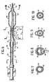
- Figs. 1-5schematically illustrate an over-the-wire dilatation catheter embodying features of the invention.
- the catheterincludes an elongated catheter body 10 which has an inner tubular member 11 with an inner lumen 12, an outer tubular member 13 disposed about the inner tubular member and defining therebetween an annular inner lumen 14 which extends through the proximal portion of the catheter body.
- An adapter 15is secured to the proximal ends of the inner and outer tubular members 11 and 13.
- a relatively inelastic, inflatable balloon 16is formed as part of the outer tubular member 13 with the distal end of the balloon secured to the distal end of the inner tubular member 11.
- the balloon 16may be formed from the same tubing as the outer tubular member 13 as shown in Fig. 1 or it may be made separately and secured to the distal end of the outer tubular member as shown in Figs. 6 and 11.
- the outer tubular member 13generally has a distal section 17 with small transverse dimensions in at least one direction, preferably smaller than an adjacent portion of the outer tubular member. As best shown in Figs. 1 and 3, a length 18 of the small diameter distal section 17 is bonded to the exterior of the inner tubular member 11 with a significant portion of the periphery outer member, typically about 50% to about 80%, being bonded to the inner member. The unbonded portion 19 of the distal section 17 along the length 18 forms an inflation lumen 20 which is in fluid communication with the interior of the balloon 16 and the annular lumen 14.
- Figs. 1-5generally follows conventional PTCA practices with over-the-wire dilatation catheters.
- a guidewire 21is backloaded into the inner lumen 12 of the inner tubular member 11 of the catheter body 10 and both the guidewire and the catheter are advanced together through a guiding catheter (not shown) which has been previously disposed within the patient's arterial system, with the distal end of the guiding catheter seated within the ostium of the desired coronary artery.
- the guidewire 21is advanced out the distal end of the guiding catheter into the patient's coronary anatomy until it crosses the lesion to be dilated, and then the dilatation catheter is advanced over the guidewire which is being held in its position, until the balloon 16 on the dilatation catheter is properly disposed within the stenotic region so that the lesion is dilated upon the inflation of the balloon. After the dilatation, the balloon 16 is deflated and the catheter and the guidewire are withdrawn from the patient.
- the guidewirecan be replaced with an exchange wire before removing the dilatation catheter so that the first catheter can be removed and another advanced into the desired location or an extension wire can be attached to the proximal end of the guidewire in place to perform essentially the same function. See the discussion of exchange wires and extension wires in U.S. Patent 4,827,941 ( Taylor et al. ) which has been incorporated herein by reference.
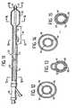
- Figs. 6-10schematically illustrate another dilatation catheter embodying features of the invention which is quite similar in its distal structure to the embodiment shown in Figs. 1-5.
- the catheter body 30includes an outer tubular member 31 which has a two layered proximal portion 32 which has an outer plastic tubular element 33 which fits tightly, e.g. is shrunk fit, onto an inner tubular element 34, an adapter 35 is secured to the proximal end of the catheter body.
- the outer plastic tubular element 33extends beyond the distal end of the inner tubular element 34 and a relatively inelastic balloon 36 is secured by its proximal end to the distal end of the outer plastic element 33 of the outer tubular member 31.
- the distal end of the balloon 36is bonded to the distal end of the inner tubular member 37.
- the outer plastic tubular element 33 of the outer tubular member 31has a distal section 38 which is an extension of the outer plastic element with small dimensions in at least one transverse direction as in the previously described embodiment.
- a significant portion of the interior surface of the distal section 38 along the length 39is bonded to the exterior of the inner tubular member 37.
- the distal end of this embodimentis quite similar to the embodiment shown in Figs. 1-5.
- the inner tubular member 37 of this embodimentis quite short compared to the inner tubular of the embodiment shown in Figs. 1-5.
- the catheter body 30is provided a guidewire port 40 which passes through the bonded walls 41 and 42 of the inner and outer tubular members 37 and 31 respectively and which is in communication with a relatively short inner lumen 43 extending within the distal portion of the inner tubular member 37.
- Guidewire 44extends proximally through the inner lumen 43 and out the proximal port 40.
- the coil 45 on the distal end of the guidewire 44extends out the distal port 46 in the distal end 47 of the catheter body 30.
- the inner tubular element 34 onto which the outer plastic tubular element 33 is securedis preferably hypotubing and may be formed of stainless steel or a NiTi alloy, particularly a NiTi alloy with superelastic properties, such as described in co-pending application Serial No 07/629,381, filed December 18, 1990, entitled Superelastic Guiding Member and assigned to the present assignee, Advanced Cardiovascular Systems, Inc.
- the upper portion thereofis removed to expose the inner lumen 48 to the interior of the balloon 36 to allow inflation fluid to be directed thereto.
- a slit 49is preferably provided in the bonded portions of the inner and outer tubular members 37 and 31 extending from the guidewire port 40 to a location adjacent the proximal end of the balloon 36.
- the slit 49greatly facilitates the removal of the catheter from the proximal end of the guidewire 44 when the catheter is to be replaced or exchanged for another catheter and it also eliminates the need for using a guidewire extension or an exchange wire as described in Horzewski et al., which has been incorporated herein by reference.
- a dual lumen type constructionsuch as described in Horzewski et al. may also be used in the portion of the catheter proximal to the guidewire port 40.
- the first methodis for the most part the same as in the prior embodiment, namely, the guidewire 44 is preloaded into the short inner lumen 43 of the inner tubular member 37 of the catheter body 30 and both are advanced through a guiding catheter (not shown) previously disposed within the patient's arterial system with the distal end of the guiding catheter seated within the ostium of a coronary artery.
- the second modefrequently called the "bare wire” technique, involves first advancing a guidewire 44 through and out the guiding catheter until it is positioned within the patient's coronary artery across the lesion to be dilated.
- the proximal end of the guidewire 44which is outside the patient, is backloaded, i.e. inserted into the short inner lumen 43 of the inner tubular member 37 and advanced proximally therein until it exits the guidewire port 40.
- the proximal end of the guidewire 44is held in place and the catheter is advanced over the guidewire through the patient's vascular system until the dilatation balloon 36 on the catheter is positioned across the stenotic region so that the stenosis can be dilated upon the inflation of the balloon.
- the balloon 36is deflated and the catheter may be removed from the patient's artery. If other treatments are necessary, the catheter is slidably removed over the guidewire 44, leaving the guidewire in place so that other catheters can be advanced over the in-place guidewire in a similar manner without the need for exchange wires or guidewire extensions.
- Figs. 11 through 15illustrate yet another dilatation catheter embodying features of the invention which provides for the perfusion of blood distal to the catheter during the dilatation of a stenotic lesion.
- the catheterincludes the catheter body 50, an inner tubular member 51 which has an inner lumen 52, an outer tubular member 53 which is disposed about the inner tubular member and which defines an annular lumen 54 located between the inner and outer tubular members, an adapter 55 secured to the ends of the inner and outer members, and a relatively inelastic balloon 56 which is secured by its proximal end to the distal end of the outer tubular member 53 and by its distal end to the distal end of the inner tubular member 51.
- the outer tubular member 53has a distal section 57 a length of 58 of which is bonded to the exterior of the inner tubular member 51 as previously described in the first two embodiments of the invention.
- the above-described portion of this embodimenthas essentially the same structure as the embodiments shown in Figs. 1-10.
- the dilatation catheter shown in Figs. 11-15differs from the other embodiments in that it has a plurality of perfusion ports 59 proximal to the balloon 56 which pass through the bonded walls 60 and 61 of the inner and outer tubular members 51 and 53 respectively and which are in fluid communication with the inner lumen 52 of the inner tubular member 51. Additionally, one or more perfusion ports 62 are provided distal to the balloon 56 through the wall 60 of the inner tubular member 51 and are in fluid communication with the inner lumen 52 extending therein.
- the balloon 56when the balloon 56 is inflated during an angioplasty procedure within a patient's vasculature, oxygenated blood is forced to pass through the proximal perfusion ports 59, through the inner lumen 52 and then out the distal perfusion ports 62 to provide oxygenated blood distal to the catheter and thereby avoid the generation of ischemic conditions in tissue downstream thereof.
- the transverse dimensions of the inner tubular member 51 within the bonded sectionare preferably larger than in the embodiments previously discussed to allow for an increased flow of blood therethrough.
- Figs. 11-15The use of the embodiment shown in Figs. 11-15 is essentially the same as the embodiment shown in Figs. 1-5. The only essential difference is that the balloon 56 can be inflated for significantly longer periods, e.g. typically about 20-30 minutes but possibly up to 5 hours or more, than the first described embodiment because oxygenated blood is flowing to the tissue distal to the inflated balloon.
- the dilatation catheter shown in Figs. 11-15may be modified by providing a guidewire port at the proximal end of the section 58, proximal to the portion of the small diameter distal section 57 in which the proximal perfusion ports 59 are located.
- the guidewire portshould be spaced sufficiently far proximally from the portion of the bonded distal section 57 having the perfusion ports 59 so that the guidewire can be pulled proximally and remain within the inner lumen 52 while the balloon 56 is inflated during the dilatation but not interfere with the flow of blood through the perfusion ports 59 and 62 and the inner lumen 52.
- the guidewirecan then be advanced distally through the inner lumen 52 and out the distal end thereof in order to maintain access to the lesion in case further treatment or diagnosis is necessary or desirable.
- the above described cathetersmay be made by conventional techniques well known to those skilled in the art. Many suitable techniques are described in the references incorporated herein.
- the small diameter distal sections 17, 38 and 57may be formed by heat shrinking the portion of the outer tubular members 13, 31 and 53 which form the distal sections onto the underlying inner members 11, 37 and 51.
- a mandrel(not shown) is disposed in the space between the inner and outer tubular members 11, 37 and 51 and 13, 31 and 53 so that upon the heat shrinking of the outer tubular member an inflation lumen is formed through the distal sections which is in fluid communication with the lumen in the proximal portion of the catheter body and the interior of the balloon 16. This bonds the small dimensioned distal section to the inner tubular member.
- a mandrelmay be inserted into the inner lumen of the inner tubular member to support the latter during the heat shrinking of the outer tubular member thereon.
- Alternate methodsmay be employed to make the small dimensioned distal section.
- the small dimensioned distal section 17may be preformed and then be adhesively bonded to the exterior of the inner tubular member.
- Multiple lumens similar to the inflation lumenmay be formed in the small dimensioned section, such as the top and bottom thereof, by employing multiple mandrels when heat shrinking the outer tubular member onto the exterior of the inner tubular member.
- the various components of the catheters and guidewires of the inventioncan be formed from a wide variety of conventional materials.
- the inner and outer plastic tubular membersmay be made from polyethylene, polyimide, polyvinyl chloride and other suitable plastic materials.
- the hypotubingmay be formed of stainless steel, NiTi superelastic alloys or other suitable materials. Composite materials such as described in co-pending application Serial No. 07/241,047, filed September 6, 1988 (which is incorporated herein by reference thereto) may also be used.
- the balloonmay be made from polyethylene, polyethylene terephthalate and other relatively inelastic polymers and other materials.
- the dimensions of the cathetersgenerally follow the dimensions of conventional intravascular catheters.
- the lengthis typically about 135 cm and the outer diameter of the outer tubular member is about 0.02 to about 0.06 inch.
- the small dimensioned distal sectionis long enough ( e.g. preferably about 10 to about 40 cm) to ensure that it is the only portion of the catheter body proximal to the balloon which exits the guiding catheter and enters the patient's coronary anatomy during intravascular procedures.
- the transverse dimensions of the cathetermay be larger with catheters for use in peripheral arteries and other locations.
Landscapes
- Health & Medical Sciences (AREA)
- Life Sciences & Earth Sciences (AREA)
- Heart & Thoracic Surgery (AREA)
- Anesthesiology (AREA)
- Hematology (AREA)
- Biophysics (AREA)
- Pulmonology (AREA)
- Engineering & Computer Science (AREA)
- Veterinary Medicine (AREA)
- Biomedical Technology (AREA)
- Public Health (AREA)
- Animal Behavior & Ethology (AREA)
- General Health & Medical Sciences (AREA)
- Child & Adolescent Psychology (AREA)
- Vascular Medicine (AREA)
- Media Introduction/Drainage Providing Device (AREA)
- Ultra Sonic Daignosis Equipment (AREA)
Description
- This invention generally relates to intravascular catheters, such asballoon dilatation catheters used in percutaneous transluminal coronary angioplasty(PTCA).
- In classic PTCA procedures, a guiding catheter having a preshapeddistal tip is percutaneously introduced into the cardiovascular system of a patientand advanced therein until the preshaped distal tip of the guiding catheter isdisposed within the aorta adjacent the ostium of the desired coronary artery. Theguiding catheter is twisted or torqued from the proximal end to turn the distal tipof the guiding catheter so that it can be guided into the coronary ostium. Aguidewire and a balloon dilatation catheter are introduced into and advancedthrough the guiding catheter to the distal tip thereof, with the guidewire slidablydisposed within an inner lumen of the dilatation catheter. The guidewire is firstadvanced out the distal tip of the guiding catheter, which is seated in the ostium ofthe patient's coronary artery, until the distal end of the guidewire crosses the lesionto be dilated. The dilatation catheter is then advanced out of the distal tip of theguiding catheter, over the previously advanced guidewire, until the balloon on thedistal extremity of the dilatation catheter is properly positioned across the lesion.Once properly positioned, the balloon is inflated to a predetermined size withradiopaque liquid at relatively high pressures (e.g ., generally 4-12 atmospheres) todilate the stenosed region of the diseased artery. The balloon is then deflated sothat the dilatation catheter can be removed from the dilated stenosis and bloodflow will resume therethrough.
- Further details of guiding catheters, dilatation catheters, guidewires,and other devices for angioplasty procedures can be found in U.S. Patent 4,323,071(Simpson-Robert); U.S. Patent 4,439,185 (Lundquist); U.S. Patent 4,468,224(Enzmannet al.); U.S. Patent 4,516,972 (Samson); U.S. Patent 4,438,622 (Samsonet al.); U.S. Patent 4,554,929 (Samsonet al.); U.S. Patent 4,582,185 (Samson);U.S. Patent 4,616,652 (Simpson); U.S. Patent 4,638,805 (Powell); U.S. Patent 4,748,986 (Morrisonet al.); U.S: Patent 4,898,577 (Badgeret al.); and U.S.Patent4,827,943 (Tayloret al.) which are hereby incorporated herein in their entirety by
- U.S. Patent 4,892,519 (Souger et al) discloses a steerable dilatation catheter with perfusion holes and an inner tubular element placed eccentrically to the outer tubular element and bonded at the prior contact between the two members.
- Several notable improvements have recently been made in balloonangioplasty catheters. One such modification is described in U.S. Patent 4,748,982(Horzewskiet al.) wherein a short sleeve or inner lumen at least about 10 cm inlength is provided within the distal section of the catheter body which extends froma first port proximal to the balloon to a second port in the distal end of thecatheter and which is adapted to slidably receive a guidewire. The proximal portis not less than about 10 cm and not more than about 40 cm from the distal endof the catheter. Preferably, a slit is provided in the catheter body extending fromthe proximal port to a location proximal to the proximal end of the balloon tofacilitate the removal of the catheter from the proximal end of the guidewire whichextends out of the patient.
- Another modification, which was introduced into the market place bythe assignee of the present application (Advanced Cardiovascular Systems, Inc.),provides a plurality of perfusion ports in the wall forming at least part of thecatheter body proximal to the balloon. These perfusion ports are in fluidcommunication with an inner lumen extending to the distal end of the catheterbody. A plurality of perfusion ports are preferably provided in the catheter bodydistal to the balloon which are also in fluid communication with the inner lumenextending to the distal end of the catheter body. When the balloon on the distalextremity of the dilatation catheter is inflated to dilate a stenosis, oxygenated bloodin the artery or the aorta or both, depending upon the location of the dilatationcatheter within the coronary anatomy, is forced to pass through the proximalperfusion ports, through the inner lumen of the catheter body and out the distalperfusion ports. This provides oxygenated blood downstream from the inflatedballoon to thereby prevent or minimize ischemic conditions in tissue distal to thecatheter. As is appreciated by those skilled in the art, tissue distal to a stenosis isfrequently already in jeopardy due to ischemic conditions which may exist. As aresult, care must be exercised in sizing the perfusion ports and the inner lumen toensure that there is adequate flow of oxygenated blood to tissue distal to the catheter to eliminate or minimize ischemic conditions.
- A major and continual thrust of development work in the field ofintravascular catheters, particularly angioplasty catheters, has been to reduce theprofile, i.e. transverse dimensions, of such catheters and to improve the flexibilitythereof without detrimentally affecting the pushability, particularly in the distalportion of such catheters. A reduction in profile with no loss in pushability allowan intravascular catheter to be advanced much further into a patient's vasculatureand to cross much tighter lesions in the case of angioplasty catheters.
- Despite many advances in this field, the need for lower profileintravascular catheters having greater flexibility with little or no loss in pushabilityremains. The present invention satisfies this need.
- The present invention is directed to an intravascular catheter havinga low profile, particularly in the distal portion thereof, and having improvedflexibility, as claimed in claim 1 enclosed herein. Additionalembodiments are claimed in the dependent claims.
- Broadly, disclosed herein is an elongated catheter for performingintravascular therapeutic or diagnostic procedures comprising: an inner tubularmember having a first inner lumen and a distal end with a port in communicationwith the first inner lumen, both the inner lumen and the port being adapted toslidably receive a guidewire; and an outer tubular member disposed about the innertubular member having a section in a distal portion of the catheter which has atleast 5% of the inner periphery thereof bonded to the exterior of the inner tubularmember, with the bonded portion taking the shape of the exterior of the innertubular member and the section having an unbonded portion defining a secondinner lumen extending longitudinally between the inner and outer tubular members.
- The intravascular catheter of the invention generally includes, at leastin the distal portion thereof, an inner tubular member having an inner lumenextending therein and an outer tubular member disposed about the inner tubularmember. In the distal portion a length of the outer tubular member is bonded toa substantial part of the inner surface or inner periphery thereof to the outer surface of the inner tubular member. At least about 5% to about 90%, preferablyabout 30% to about 80%, of the periphery of the outer tubular member is bondedto the underlying inner tubular member so that the bonded portion of the outermember takes the shape of the inner tubular member to which it is bonded. Theunbonded portion of the outer tubular member along said length defines with theinner tubular member a longitudinally extending inner lumen. The bond need notbe continuous and may be intermittent so long as a significant portion thereof isbonded. The bonded section may extend along essentially the entire length of thecatheter but should not be less than about 5 mm. Preferably, the length of thebonded section is about 10 cm to about 40 cm. The catheter is provided with adiagnostic or treatment means such as an inflatable dilatation balloon forangioplasty distal to the bonded section.
- By bonding a length of the outer tubular member in the distal portionof the catheter to the exterior of the inner member, the profile of the catheter bodyin at least one transverse dimension in that area is reduced substantially to therebyprovide improved flexibility. Moreover, the bonded portions of the inner memberand the outer tubular members support one another thereby providingimprovements in the pushability of the catheter. Substantial reductions in only onetransverse dimension can provide substantial improvements in flexibility. Minimumcross-sectional dimensions of the small diameter section of the outer tubularmember for coronary dilatation catheters are on the order of about 0.02 to about0.06 in.(0.51 - 1.5 mm). For peripheral arteries this dimension may be larger. Thepushability of the reduced diameter bonded section of the catheter body is alsofrequently improved.
- The improvements of the invention are applicable to a wide range ofintravascular catheters and particularly to essentially all types of dilatation catheterswith inflatable or expandable members, such as those described in the patentsincorporated herein by reference. These and other advantages of the invention willbecome more apparent from the following detailed description of the inventionwhen taken in conjunction with accompanying exemplary drawings.
- Fig. 1 is an elevational view, partially in section, of a balloondilatation catheter embodying features of the invention.
- Fig. 2 is a transverse cross-sectional view of the catheter shown inFig. 1 taken along the lines 2-2.
- Fig. 3 is a transverse cross-sectional view of the catheter shown inFig. 1 taken along the lines 3-3.
- Fig. 4 is a transverse cross-sectional view of the catheter shown inFig. 1 taken along the lines 4-4.
- Fig. 5 is a transverse cross-sectional view of the catheter shown inFig. 1 taken along the lines 5-5.
- Fig. 6 is an elevational view, partially in section, of another dilatationcatheter embodying features of the invention.
- Fig. 7 is a transverse cross-sectional view of the catheter shown inFig. 6 taken along the lines 7-7.
- Fig. 8 is a transverse cross-sectional view of the catheter shown inFig. 6 taken along the lines 8-8.
- Fig. 9 is a transverse cross-sectional view of the catheter shown inFig. 6 taken along the lines 9-9.
- Fig. 10 is a transverse cross-sectional view of the catheter shown inFig. 6 taken along the lines 10-10.
- Fig. 11 is an elevational view, partially in section, of anotherdilatation catheter embodying features of the invention.
- Fig. 12 is a transverse cross-sectional view of the catheter shown inFig. 11 taken along the lines 12-12.
- Fig. 13 is a transverse cross-sectional view of the catheter shown inFig. 11 taken along the lines 13-13.
- Fig. 14 is a transverse cross-sectional view of the catheter shown inFig. 11 taken along the lines 14-14.
- Fig. 15 is a transverse cross-sectional view of the catheter shown inFig. 11 taken along the lines 15-15.
- Figs. 1-5 schematically illustrate an over-the-wire dilatation catheterembodying features of the invention. The catheter includes an
elongated catheterbody 10 which has an innertubular member 11 with aninner lumen 12, an outertubular member 13 disposed about the inner tubular member and definingtherebetween an annularinner lumen 14 which extends through the proximalportion of the catheter body. An adapter 15 is secured to the proximal ends of theinner and outertubular members inflatableballoon 16 is formed as part of the outertubular member 13 with the distal end ofthe balloon secured to the distal end of theinner tubular member 11. Theballoon 16 may be formed from the same tubing as the outertubular member 13 as shownin Fig. 1 or it may be made separately and secured to the distal end of the outertubular member as shown in Figs. 6 and 11. - The outer
tubular member 13 generally has adistal section 17 withsmall transverse dimensions in at least one direction, preferably smaller than anadjacent portion of the outer tubular member. As best shown in Figs. 1 and 3, alength 18 of the small diameterdistal section 17 is bonded to the exterior of theinner tubular member 11 with a significant portion of the periphery outer member,typically about 50% to about 80%, being bonded to the inner member. Theunbonded portion 19 of thedistal section 17 along thelength 18 forms aninflationlumen 20 which is in fluid communication with the interior of theballoon 16 andtheannular lumen 14. - The use of the dilatation catheter shown in Figs. 1-5 generally followsconventional PTCA practices with over-the-wire dilatation catheters. A
guidewire 21 is backloaded into theinner lumen 12 of theinner tubular member 11 of thecatheter body 10 and both the guidewire and the catheter are advanced togetherthrough a guiding catheter (not shown) which has been previously disposed withinthe patient's arterial system, with the distal end of the guiding catheter seatedwithin the ostium of the desired coronary artery. Theguidewire 21 is advanced outthe distal end of the guiding catheter into the patient's coronary anatomy until itcrosses the lesion to be dilated, and then the dilatation catheter is advanced overthe guidewire which is being held in its position, until theballoon 16 on thedilatation catheter is properly disposed within the stenotic region so that the lesionis dilated upon the inflation of the balloon. After the dilatation, theballoon 16 isdeflated and the catheter and the guidewire are withdrawn from the patient. Iffurther treatment or diagnosis is to be conducted, the guidewire can be replacedwith an exchange wire before removing the dilatation catheter so that the firstcatheter can be removed and another advanced into the desired location or anextension wire can be attached to the proximal end of the guidewire in place toperform essentially the same function. See the discussion of exchange wires andextension wires in U.S. Patent 4,827,941 (Taylor et al.) which has been incorporatedherein by reference. - Figs. 6-10 schematically illustrate another dilatation catheterembodying features of the invention which is quite similar in its distal structure tothe embodiment shown in Figs. 1-5. In the embodiment shown in Figs. 6-10, the
catheter body 30 includes anouter tubular member 31 which has a two layeredproximal portion 32 which has an outer plastictubular element 33 which fits tightly,e.g. is shrunk fit, onto an innertubular element 34, anadapter 35 is secured to the proximal end of the catheter body. The outer plastictubular element 33 extendsbeyond the distal end of the innertubular element 34 and a relativelyinelasticballoon 36 is secured by its proximal end to the distal end of the outerplasticelement 33 of the outertubular member 31. The distal end of theballoon 36 isbonded to the distal end of theinner tubular member 37. The outer plastictubularelement 33 of the outertubular member 31 has adistal section 38 which is anextension of the outer plastic element with small dimensions in at least onetransverse direction as in the previously described embodiment. A significantportion of the interior surface of thedistal section 38 along the length 39 is bondedto the exterior of theinner tubular member 37. To this extent, the distal end ofthis embodiment is quite similar to the embodiment shown in Figs. 1-5. Theinnertubular member 37 of this embodiment is quite short compared to the inner tubularof the embodiment shown in Figs. 1-5. - In the embodiment shown in Figs. 6-10, the
catheter body 30 isprovided aguidewire port 40 which passes through the bondedwalls tubular members inner lumen 43 extending within the distalportion of theinner tubular member 37.Guidewire 44 extends proximally throughtheinner lumen 43 and out theproximal port 40. Thecoil 45 on the distal end oftheguidewire 44 extends out thedistal port 46 in thedistal end 47 of thecatheterbody 30. The innertubular element 34 onto which the outer plastictubular element 33 is secured is preferably hypotubing and may be formed of stainless steel or aNiTi alloy, particularly a NiTi alloy with superelastic properties, such as describedin co-pending application Serial No 07/629,381, filed December 18, 1990, entitledSuperelastic Guiding Member and assigned to the present assignee, AdvancedCardiovascular Systems, Inc. At the distal extremity of the innertubular element 34, the upper portion thereof is removed to expose theinner lumen 48 to theinterior of theballoon 36 to allow inflation fluid to be directed thereto. It ispresently preferred to secure the proximal end of theinner tubular member 37 tothe lower portion of the distal extremity of the inner tubular element or hypotubingby heat shrinking the outer plastictubular element 33 onto the inner tubularelement with the flattened end of the inner tubular member disposed therebetween. The catheter construction of this embodiment with a relatively short inner lumenwhich is adapted to slidably receive a guidewire therein eliminates the need forusing an exchange wire or a guidewire extension. Aslit 49 is preferably providedin the bonded portions of the inner and outertubular members guidewire port 40 to a location adjacent the proximal end of theballoon 36. Theslit 49 greatly facilitates the removal of the catheter from the proximal endof theguidewire 44 when the catheter is to be replaced or exchanged for anothercatheter and it also eliminates the need for using a guidewire extension or anexchange wire as described in Horzewskiet al., which has been incorporated hereinby reference. A dual lumen type construction such as described in Horzewskiet al.may also be used in the portion of the catheter proximal to theguidewire port 40. - There are at least two modes of inserting the dilatation catheter ofthis embodiment into the patient's coronary anatomy. The first method is for themost part the same as in the prior embodiment, namely, the
guidewire 44 ispreloaded into the shortinner lumen 43 of theinner tubular member 37 of thecatheter body 30 and both are advanced through a guiding catheter (not shown)previously disposed within the patient's arterial system with the distal end of theguiding catheter seated within the ostium of a coronary artery. The second mode,frequently called the "bare wire" technique, involves first advancing aguidewire 44through and out the guiding catheter until it is positioned within the patient'scoronary artery across the lesion to be dilated. The proximal end of theguidewire 44, which is outside the patient, is backloaded,i.e. inserted into the shortinnerlumen 43 of theinner tubular member 37 and advanced proximally therein until itexits theguidewire port 40. The proximal end of theguidewire 44 is held in placeand the catheter is advanced over the guidewire through the patient's vascularsystem until thedilatation balloon 36 on the catheter is positioned across thestenotic region so that the stenosis can be dilated upon the inflation of the balloon.After the dilatation of the lesion, theballoon 36 is deflated and the catheter maybe removed from the patient's artery. If other treatments are necessary, thecatheter is slidably removed over theguidewire 44, leaving the guidewire in placeso that other catheters can be advanced over the in-place guidewire in a similarmanner without the need for exchange wires or guidewire extensions. - Figs. 11 through 15 illustrate yet another dilatation catheterembodying features of the invention which provides for the perfusion of blood distalto the catheter during the dilatation of a stenotic lesion. The catheter includes the
catheter body 50, aninner tubular member 51 which has aninner lumen 52, anouter tubular member 53 which is disposed about the inner tubular member andwhich defines anannular lumen 54 located between the inner and outer tubularmembers, anadapter 55 secured to the ends of the inner and outer members, anda relativelyinelastic balloon 56 which is secured by its proximal end to the distalend of the outertubular member 53 and by its distal end to the distal end of theinner tubular member 51. The outertubular member 53 has a distal section 57 alength of 58 of which is bonded to the exterior of theinner tubular member 51 aspreviously described in the first two embodiments of the invention. The above-describedportion of this embodiment has essentially the same structure as theembodiments shown in Figs. 1-10. - The dilatation catheter shown in Figs. 11-15 differs from the otherembodiments in that it has a plurality of
perfusion ports 59 proximal to theballoon 56 which pass through the bonded walls 60 and 61 of the inner and outertubularmembers inner lumen 52 of theinner tubular member 51. Additionally, one ormoreperfusion ports 62 are provided distal to theballoon 56 through the wall 60 of theinner tubular member 51 and are in fluid communication with theinner lumen 52extending therein. In this manner, when theballoon 56 is inflated during anangioplasty procedure within a patient's vasculature, oxygenated blood is forced topass through theproximal perfusion ports 59, through theinner lumen 52 and thenout thedistal perfusion ports 62 to provide oxygenated blood distal to the catheterand thereby avoid the generation of ischemic conditions in tissue downstreamthereof. The transverse dimensions of theinner tubular member 51 within thebonded section are preferably larger than in the embodiments previously discussedto allow for an increased flow of blood therethrough. - The use of the embodiment shown in Figs. 11-15 is essentially thesame as the embodiment shown in Figs. 1-5. The only essential difference is thatthe
balloon 56 can be inflated for significantly longer periods,e.g. typically about 20-30 minutes but possibly up to 5 hours or more, than the first describedembodiment because oxygenated blood is flowing to the tissue distal to the inflatedballoon. - The dilatation catheter shown in Figs. 11-15 may be modified byproviding a guidewire port at the proximal end of the section 58, proximal to theportion of the small diameter
distal section 57 in which theproximal perfusionports 59 are located. However, the guidewire port should be spaced sufficiently farproximally from the portion of the bondeddistal section 57 having theperfusionports 59 so that the guidewire can be pulled proximally and remain within theinnerlumen 52 while theballoon 56 is inflated during the dilatation but not interferewith the flow of blood through theperfusion ports inner lumen 52. After the angioplasty procedure is completed, the guidewire can then beadvanced distally through theinner lumen 52 and out the distal end thereof inorder to maintain access to the lesion in case further treatment or diagnosis isnecessary or desirable. - The use of the catheter with both perfusion ports and a guidewireport as described above is essentially the same as the use of the dilatation catheterillustrated in Figs. 5-10, but with the additional advantage that long term dilatationsare possible.
- The above described catheters may be made by conventionaltechniques well known to those skilled in the art. Many suitable techniques aredescribed in the references incorporated herein. The small diameter
distal sections tubularmembers innermembers tubular members balloon 16. Thisbonds the small dimensioned distal section to the inner tubular member. Amandrel may be inserted into the inner lumen of the inner tubular member tosupport the latter during the heat shrinking of the outer tubular member thereon. Alternate methods may be employed to make the small dimensioned distal section.For example, the small dimensioneddistal section 17 may be preformed and thenbe adhesively bonded to the exterior of the inner tubular member. Multiple lumenssimilar to the inflation lumen may be formed in the small dimensioned section,such as the top and bottom thereof, by employing multiple mandrels when heatshrinking the outer tubular member onto the exterior of the inner tubular member. - The various components of the catheters and guidewires of theinvention can be formed from a wide variety of conventional materials. The innerand outer plastic tubular members may be made from polyethylene, polyimide,polyvinyl chloride and other suitable plastic materials. The hypotubing may beformed of stainless steel, NiTi superelastic alloys or other suitable materials.Composite materials such as described in co-pending application Serial No.07/241,047, filed September 6, 1988 (which is incorporated herein by referencethereto) may also be used. The balloon may be made from polyethylene,polyethylene terephthalate and other relatively inelastic polymers and othermaterials.
- The dimensions of the catheters generally follow the dimensions ofconventional intravascular catheters. For coronary use the length is typically about135 cm and the outer diameter of the outer tubular member is about 0.02 to about0.06 inch. In a presently preferred embodiment, the small dimensioned distalsection is long enough (e.g. preferably about 10 to about 40 cm) to ensure that itis the only portion of the catheter body proximal to the balloon which exits theguiding catheter and enters the patient's coronary anatomy during intravascularprocedures. The transverse dimensions of the catheter may be larger with cathetersfor use in peripheral arteries and other locations.
- While the invention has been described herein primarily in terms ofcatheters for coronary angioplasty, the invention may be employed in a wide varietyof catheters for insertion into various body lumens. Additionally, modifications andimprovements can be made to the invention without departing from the scopethereof.
Claims (9)
- An elongated catheter for insertion into a body lumen, the cathetercomprising:the catheter beingcharacterized in that said length of the distal shaft section isnot greater than about 40 cm and the distal shaft section has a transversecross-section along the said length being substantially larger in a firstdirection than in a second direction perpendicular to the first direction,inthat, along said length of the distal shaft section, about 30% to about 90% ofthe circumference of the inner periphery of the outer tubular member (13, 33,53) is disposed about and secured to the inner tubular member (11, 37, 51),andin that said diagnostic or treatment means (16, 36, 56) is at a locationdistal to said length of the distal shaft section.a) an elongated catheter shaft (10, 30, 50) which has a distal shaftsection (17, 38, 57) with an inner tubular member (11, 37, 51) having a firstinner lumen (12, 48, 52) and a distal end (47) with a port (46) incommunication with the first inner lumen (12, 48, 52) and an outer tubularmember (13, 33, 53) disposed about the inner tubular member (11, 37, 51)secured along a length of the distal shaft section of at least about 10 cm to theexterior of the inner tubular member (11, 37, 51) and the outer tubularmember (13, 33, 53) having along said length a portion unsecured to theexterior of the inner tubular member (11, 37, 51), being longitudinally off-setand coextensive with the portion secured and having a second inner lumen(20) extending longitudinally between the inner tubular member (11, 37, 51)and the unsecured portion of the outer tubular member; andb) diagnostic or treatment means (16, 36, 56),
- The elongated catheter of claim 1, wherein said diagnostic or treatment means(16, 36, 56) is an inflatable balloon.
- The elongated catheter of Claim 2 wherein said outer tubular member (13, 33, 53) issecured to the exterior of said inner tubular member (11, 37, 51) by shrunk fitting.
- The elongated catheter of Claim 3 wherein at least one perfusion port (59) extendsthrough secured walls of the outer tubular member (13, 33, 53) and the inner tubularmember (11, 37, 51) and is in fluid communication with the inner lumen (12, 48, 52) ofthe inner tubular member (11, 37, 51).
- The elongated catheter of Claim 4 wherein at least one perfusion port (62) is providedin the inner tubular member (11, 37, 51) distal to the balloon (16, 36, 56) which is in fluidcommunication with the inner lumen (12,48,52) thereof.
- The elongated catheter of Claim 2 wherein the inner tubular member (11, 37, 51) ontowhich the outer tubular member (13, 33, 53) is secured is hypotubing.
- The elongated catheter of Claim 3, wherein said inflatable balloon (16, 36, 56) has aninterior in fluid communication with the second inner lumen (20).
- The elongated catheter of Claim 3, wherein a portion of the inner tubular member (11, 37, 51) proximal to the portion (18, 38, 58) thereof secured to the outer tubular member(13,33, 53) is provided with a stiffening member.
- The elongated catheter of Claim 3 including a guidewire receiving port (40) which islocated proximal to the diagnostic or treatment means (16, 36, 56) and which is incommunication with the inner lumen (12, 48, 52) of the inner tubular member (11, 37,51).
Applications Claiming Priority (3)
| Application Number | Priority Date | Filing Date | Title |
|---|---|---|---|
| US70061791A | 1991-05-15 | 1991-05-15 | |
| US700617 | 1991-05-15 | ||
| EP92108238AEP0513818B1 (en) | 1991-05-15 | 1992-05-15 | Low profile dilatation catheter |
Related Parent Applications (1)
| Application Number | Title | Priority Date | Filing Date |
|---|---|---|---|
| EP92108238ADivisionEP0513818B1 (en) | 1991-05-15 | 1992-05-15 | Low profile dilatation catheter |
Publications (3)
| Publication Number | Publication Date |
|---|---|
| EP0931562A2 EP0931562A2 (en) | 1999-07-28 |
| EP0931562A3 EP0931562A3 (en) | 1999-08-04 |
| EP0931562B1true EP0931562B1 (en) | 2004-07-28 |
Family
ID=24814226
Family Applications (2)
| Application Number | Title | Priority Date | Filing Date |
|---|---|---|---|
| EP92108238AExpired - LifetimeEP0513818B1 (en) | 1991-05-15 | 1992-05-15 | Low profile dilatation catheter |
| EP99106636AExpired - LifetimeEP0931562B1 (en) | 1991-05-15 | 1992-05-15 | Low profile dilatation catheter |
Family Applications Before (1)
| Application Number | Title | Priority Date | Filing Date |
|---|---|---|---|
| EP92108238AExpired - LifetimeEP0513818B1 (en) | 1991-05-15 | 1992-05-15 | Low profile dilatation catheter |
Country Status (5)
| Country | Link |
|---|---|
| US (1) | US5496275A (en) |
| EP (2) | EP0513818B1 (en) |
| JP (1) | JP3399556B2 (en) |
| CA (1) | CA2068483A1 (en) |
| DE (2) | DE69233390T2 (en) |
Families Citing this family (102)
| Publication number | Priority date | Publication date | Assignee | Title |
|---|---|---|---|---|
| US5484409A (en)* | 1989-08-25 | 1996-01-16 | Scimed Life Systems, Inc. | Intravascular catheter and method for use thereof |
| US5318529A (en)* | 1989-09-06 | 1994-06-07 | Boston Scientific Corporation | Angioplasty balloon catheter and adaptor |
| US5743875A (en)* | 1991-05-15 | 1998-04-28 | Advanced Cardiovascular Systems, Inc. | Catheter shaft with an oblong transverse cross-section |
| US5833706A (en)* | 1991-07-05 | 1998-11-10 | Scimed Life Systems, Inc. | Single operator exchange perfusion catheter having a distal catheter shaft section |
| US5490837A (en)* | 1991-07-05 | 1996-02-13 | Scimed Life Systems, Inc. | Single operator exchange catheter having a distal catheter shaft section |
| US5649909A (en)* | 1992-04-06 | 1997-07-22 | Scimed Life Systems, Inc. | Variable stiffness multi-lumen catheter |
| JPH08500757A (en) | 1992-12-30 | 1996-01-30 | シュナイダー・(ユーエスエイ)・インコーポレーテッド | Device for deploying a stent implantable in the body |
| ES2118392T3 (en)* | 1993-04-09 | 1998-09-16 | Schneider Usa Inc | DILATOR CATHETER WITH FLEXIBLE CUSHION POINT. |
| EP0749333A1 (en)* | 1994-03-10 | 1996-12-27 | Schneider (Usa) Inc. | Catheter having shaft of varying stiffness |
| NL9500283A (en)* | 1994-10-21 | 1996-06-03 | Cordis Europ | Catheter with guide wire channel. |
| US5667493A (en)* | 1994-12-30 | 1997-09-16 | Janacek; Jaroslav | Dilation catheter |
| CA2209633C (en)* | 1995-01-04 | 2008-04-22 | Advanced Cardiovascular Systems, Inc. | Catheter shaft with an oblong transverse cross section |
| US5951513A (en)* | 1995-02-24 | 1999-09-14 | Advanced Cardiovascular Systems, Inc. | Balloon catheter having non-bonded integral balloon and methods for its manufacture |
| EP0792655A3 (en)* | 1996-02-29 | 1998-01-28 | Becton, Dickinson and Company | Catheter with improved extension tube |
| CA2197415A1 (en)* | 1996-02-29 | 1997-08-29 | Kenneth C. Musgrave | Catheter with improved tape down wing |
| US6488637B1 (en) | 1996-04-30 | 2002-12-03 | Target Therapeutics, Inc. | Composite endovascular guidewire |
| US5902282A (en)* | 1996-12-26 | 1999-05-11 | Johnson & Johnson Medical, Inc. | Step-down catheter |
| US6238376B1 (en)* | 1997-03-18 | 2001-05-29 | Advanced Cardiovascular Systems, Inc. | Bonding a polymer member to a metallic member |
| ATE265247T1 (en)* | 1997-06-10 | 2004-05-15 | Schneider Europ Gmbh | CATHETER SYSTEM |
| DE69828429T2 (en) | 1997-10-08 | 2005-12-08 | Kaneka Corp. | BALLOON CATHETER AND MANUFACTURING METHOD THEREFOR |
| US20100030256A1 (en) | 1997-11-12 | 2010-02-04 | Genesis Technologies Llc | Medical Devices and Methods |
| US9498604B2 (en) | 1997-11-12 | 2016-11-22 | Genesis Technologies Llc | Medical device and method |
| US6010521A (en) | 1997-11-25 | 2000-01-04 | Advanced Cardiovasular Systems, Inc. | Catheter member with bondable layer |
| US6129707A (en) | 1998-01-21 | 2000-10-10 | Advanced Cardiovascular Systems, Inc. | Intravascular catheter with expanded distal tip |
| WO2004011057A1 (en) | 1998-02-07 | 2004-02-05 | Advanced Cardiovascular Systems, Inc. | Perfusion dilatation catherer with expanded support coil |
| US6623521B2 (en) | 1998-02-17 | 2003-09-23 | Md3, Inc. | Expandable stent with sliding and locking radial elements |
| US20070142901A1 (en)* | 1998-02-17 | 2007-06-21 | Steinke Thomas A | Expandable stent with sliding and locking radial elements |
| US6475187B1 (en) | 1998-03-04 | 2002-11-05 | Scimed Life Systems, Inc. | Convertible catheter incorporating distal force transfer mechanism |
| JPH11262529A (en)* | 1998-03-18 | 1999-09-28 | Nippon Zeon Co Ltd | Balloon catheter |
| US20020007145A1 (en)* | 1998-10-23 | 2002-01-17 | Timothy Stivland | Catheter having improved bonding region |
| SE514718C2 (en)* | 1999-06-29 | 2001-04-09 | Jan Otto Solem | Apparatus for treating defective closure of the mitral valve apparatus |
| US7192442B2 (en)* | 1999-06-30 | 2007-03-20 | Edwards Lifesciences Ag | Method and device for treatment of mitral insufficiency |
| US6997951B2 (en)* | 1999-06-30 | 2006-02-14 | Edwards Lifesciences Ag | Method and device for treatment of mitral insufficiency |
| JP4263826B2 (en) | 1999-11-26 | 2009-05-13 | テルモ株式会社 | Catheter manufacturing method and catheter |
| US6402781B1 (en)* | 2000-01-31 | 2002-06-11 | Mitralife | Percutaneous mitral annuloplasty and cardiac reinforcement |
| US7296577B2 (en) | 2000-01-31 | 2007-11-20 | Edwards Lifescience Ag | Transluminal mitral annuloplasty with active anchoring |
| US6585687B1 (en)* | 2000-03-27 | 2003-07-01 | Cordis Corporation | Inflatable balloon catheter body construction |
| US6544218B1 (en) | 2000-07-26 | 2003-04-08 | Advanced Cardiovascular Systems, Inc. | Catheter with biased shaft |
| US6893456B2 (en)* | 2000-12-22 | 2005-05-17 | Advanced Cardiovascular Systems, Inc. | Catheter and method for making the same |
| US7510576B2 (en)* | 2001-01-30 | 2009-03-31 | Edwards Lifesciences Ag | Transluminal mitral annuloplasty |
| US20030100945A1 (en) | 2001-11-23 | 2003-05-29 | Mindguard Ltd. | Implantable intraluminal device and method of using same in treating aneurysms |
| US6979342B2 (en)* | 2001-09-19 | 2005-12-27 | Advanced Cardiovascular Systems, Incc | Catheter with a polyimide distal tip |
| US6863678B2 (en)* | 2001-09-19 | 2005-03-08 | Advanced Cardiovascular Systems, Inc. | Catheter with a multilayered shaft section having a polyimide layer |
| US6746423B1 (en) | 2001-11-01 | 2004-06-08 | Advanced Cardiovascular Systems, Inc. | Catheter having improved rapid exchange junction |
| US8075616B2 (en)* | 2001-12-28 | 2011-12-13 | Edwards Lifesciences Ag | Apparatus for applying a compressive load on body tissue |
| SE524709C2 (en)* | 2002-01-11 | 2004-09-21 | Edwards Lifesciences Ag | Device for delayed reshaping of a heart vessel and a heart valve |
| US6951053B2 (en)* | 2002-09-04 | 2005-10-04 | Reva Medical, Inc. | Method of manufacturing a prosthesis |
| US20040059244A1 (en)* | 2002-09-23 | 2004-03-25 | Volcano Therapeutics, Inc. | Thermography catheters allowing for rapid exchange and methods of use |
| US7323233B2 (en)* | 2002-09-26 | 2008-01-29 | Scimed Life Systems, Inc. | Sheath materials and processes |
| US6997899B2 (en)* | 2002-12-17 | 2006-02-14 | Boston Scientific Scimed, Inc, | Rapid exchange dilation catheter for non-vascular applications |
| US7273485B2 (en)* | 2003-03-20 | 2007-09-25 | Advanced Cardiovascular Systems, Inc. | Balloon catheter having a shaft with a variable stiffness inner tubular member |
| EP1646332B1 (en)* | 2003-07-18 | 2015-06-17 | Edwards Lifesciences AG | Remotely activated mitral annuloplasty system |
| US20050177228A1 (en)* | 2003-12-16 | 2005-08-11 | Solem Jan O. | Device for changing the shape of the mitral annulus |
| WO2005058206A1 (en) | 2003-12-16 | 2005-06-30 | Edwards Lifesciences Ag | Device for changing the shape of the mitral annulus |
| US7468051B2 (en)* | 2004-03-02 | 2008-12-23 | Boston Scientific Scimed, Inc. | Occlusion balloon catheter with external inflation lumen |
| US8252014B2 (en) | 2004-03-03 | 2012-08-28 | Innovational Holdings Llc. | Rapid exchange balloon catheter with braided shaft |
| US7993397B2 (en)* | 2004-04-05 | 2011-08-09 | Edwards Lifesciences Ag | Remotely adjustable coronary sinus implant |
| US7887529B2 (en)* | 2004-04-19 | 2011-02-15 | Boston Scientific Scimed, Inc. | Hybrid micro guide catheter |
| US8703113B2 (en) | 2004-07-08 | 2014-04-22 | Reva Medical Inc. | Side-chain crystallizable polymers for medical applications |
| US7763065B2 (en)* | 2004-07-21 | 2010-07-27 | Reva Medical, Inc. | Balloon expandable crush-recoverable stent device |
| US20060034769A1 (en)* | 2004-08-13 | 2006-02-16 | Rutgers, The State University | Radiopaque polymeric stents |
| EP1789097B1 (en) | 2004-08-13 | 2014-08-13 | Rutgers, The State University | Radiopaque polymeric stents |
| EP1923075B1 (en) | 2004-08-13 | 2015-11-11 | Rutgers, The State University | Radiopaque polymeric stents |
| US7211110B2 (en)* | 2004-12-09 | 2007-05-01 | Edwards Lifesciences Corporation | Diagnostic kit to assist with heart valve annulus adjustment |
| US8292944B2 (en)* | 2004-12-17 | 2012-10-23 | Reva Medical, Inc. | Slide-and-lock stent |
| US7500989B2 (en)* | 2005-06-03 | 2009-03-10 | Edwards Lifesciences Corp. | Devices and methods for percutaneous repair of the mitral valve via the coronary sinus |
| US9149378B2 (en) | 2005-08-02 | 2015-10-06 | Reva Medical, Inc. | Axially nested slide and lock expandable device |
| US7914574B2 (en) | 2005-08-02 | 2011-03-29 | Reva Medical, Inc. | Axially nested slide and lock expandable device |
| US20070038297A1 (en)* | 2005-08-12 | 2007-02-15 | Bobo Donald E Jr | Medical implant with reinforcement mechanism |
| US20080221673A1 (en)* | 2005-08-12 | 2008-09-11 | Donald Bobo | Medical implant with reinforcement mechanism |
| US20070073391A1 (en)* | 2005-09-28 | 2007-03-29 | Henry Bourang | System and method for delivering a mitral valve repair device |
| US8298210B2 (en)* | 2005-10-26 | 2012-10-30 | Medtronic Vascular, Inc. | Catheter having oval aspiration lumen and method of making |
| US7637946B2 (en)* | 2006-02-09 | 2009-12-29 | Edwards Lifesciences Corporation | Coiled implant for mitral valve repair |
| US7906066B2 (en)* | 2006-06-30 | 2011-03-15 | Abbott Cardiovascular Systems, Inc. | Method of making a balloon catheter shaft having high strength and flexibility |
| US8382738B2 (en) | 2006-06-30 | 2013-02-26 | Abbott Cardiovascular Systems, Inc. | Balloon catheter tapered shaft having high strength and flexibility and method of making same |
| US9592369B2 (en) | 2006-08-21 | 2017-03-14 | Kaneka Corporation | Balloon catheter |
| US8021352B2 (en) | 2006-08-23 | 2011-09-20 | Codman & Shurtleff, Inc. | Unfused catheter body feature and methods of manufacture |
| US20080065205A1 (en)* | 2006-09-11 | 2008-03-13 | Duy Nguyen | Retrievable implant and method for treatment of mitral regurgitation |
| CA2664682C (en) | 2006-10-17 | 2012-12-04 | Reva Medical, Inc. | N-substituted monomers and polymers |
| US20080167628A1 (en)* | 2007-01-05 | 2008-07-10 | Boston Scientific Scimed, Inc. | Stent delivery system |
| US7704275B2 (en)* | 2007-01-26 | 2010-04-27 | Reva Medical, Inc. | Circumferentially nested expandable device |
| US20080255447A1 (en)* | 2007-04-16 | 2008-10-16 | Henry Bourang | Diagnostic catheter |
| JP2008264119A (en)* | 2007-04-18 | 2008-11-06 | Kaneka Corp | Catheter with pressing property |
| US8100820B2 (en)* | 2007-08-22 | 2012-01-24 | Edwards Lifesciences Corporation | Implantable device for treatment of ventricular dilation |
| US20090069748A1 (en)* | 2007-09-12 | 2009-03-12 | Cook Incorporated | Pushable balloon catheter assembly |
| EP2211773A4 (en) | 2007-11-30 | 2015-07-29 | Reva Medical Inc | Axially-radially nested expandable device |
| US8403885B2 (en) | 2007-12-17 | 2013-03-26 | Abbott Cardiovascular Systems Inc. | Catheter having transitioning shaft segments |
| EP2331014B1 (en) | 2008-10-10 | 2017-08-09 | Reva Medical, Inc. | Expandable slide and lock stent |
| US8052638B2 (en) | 2008-11-26 | 2011-11-08 | Abbott Cardiovascular Systems, Inc. | Robust multi-layer balloon |
| US8444608B2 (en)* | 2008-11-26 | 2013-05-21 | Abbott Cardivascular Systems, Inc. | Robust catheter tubing |
| JP5809237B2 (en) | 2010-04-10 | 2015-11-10 | レヴァ メディカル、 インコーポレイテッドReva Medical, Inc. | Expandable slide lock stent |
| US9561094B2 (en) | 2010-07-23 | 2017-02-07 | Nfinium Vascular Technologies, Llc | Devices and methods for treating venous diseases |
| CN107007921B (en) | 2011-05-26 | 2020-01-21 | 雅培心血管系统有限公司 | Through tip of catheter |
| US10849771B2 (en) | 2011-06-27 | 2020-12-01 | Boston Scientific Scimed, Inc. | Stent delivery systems and methods for making and using stent delivery systems |
| EP2768568B1 (en) | 2011-10-18 | 2020-05-06 | Boston Scientific Scimed, Inc. | Integrated crossing balloon catheter |
| US8684963B2 (en) | 2012-07-05 | 2014-04-01 | Abbott Cardiovascular Systems Inc. | Catheter with a dual lumen monolithic shaft |
| US9332999B2 (en) | 2012-08-13 | 2016-05-10 | Covidien Lp | Apparatus and methods for clot disruption and evacuation |
| US9332998B2 (en) | 2012-08-13 | 2016-05-10 | Covidien Lp | Apparatus and methods for clot disruption and evacuation |
| US9408732B2 (en) | 2013-03-14 | 2016-08-09 | Reva Medical, Inc. | Reduced-profile slide and lock stent |
| JP6348486B2 (en) | 2013-04-02 | 2018-06-27 | テルモ株式会社 | Balloon catheter and method for manufacturing balloon catheter |
| EP3151904A4 (en) | 2014-06-04 | 2018-02-14 | Nfinium Vascular Technologies, LLC | Low radial force vascular device and method of occlusion |
| US20170189059A1 (en)* | 2016-01-06 | 2017-07-06 | Boston Scientific Scimed, Inc. | Percutaneous access device |
Family Cites Families (31)
| Publication number | Priority date | Publication date | Assignee | Title |
|---|---|---|---|---|
| US2248934A (en)* | 1937-12-24 | 1941-07-15 | Davol Rubber Co | Inflatable catheter |
| US2457244A (en)* | 1943-06-22 | 1948-12-28 | Otis F Lamson | Medical appliance for control of enemata |
| US2912981A (en)* | 1958-04-10 | 1959-11-17 | Frank J Keough | Inflatable retention catheter |
| US3112748A (en)* | 1960-04-04 | 1963-12-03 | Pharmaseal Lab | Surgical tube |
| US3983879A (en)* | 1974-07-25 | 1976-10-05 | Western Acadia, Incorporated | Silicone catheter |
| US4323071A (en)* | 1978-04-24 | 1982-04-06 | Advanced Catheter Systems, Inc. | Vascular guiding catheter assembly and vascular dilating catheter assembly and a combination thereof and methods of making the same |
| US4295464A (en)* | 1980-03-21 | 1981-10-20 | Shihata Alfred A | Ureteric stone extractor with two ballooned catheters |
| CA1186192A (en)* | 1982-01-27 | 1985-04-30 | David S. Hickey | Urethral catheter |
| DE3228438C2 (en)* | 1982-07-30 | 1985-01-17 | Karl Dr. 6301 Pohlheim Aigner | Double lumen catheter |
| US5102390A (en)* | 1985-05-02 | 1992-04-07 | C. R. Bard, Inc. | Microdilatation probe and system for performing angioplasty in highly stenosed blood vessels |
| DE3522782A1 (en)* | 1985-06-26 | 1987-01-15 | Peter Brehm Chir Mechanik Werk | Double-lumen follicle-biopsy cannula |
| US5040548A (en)* | 1989-06-01 | 1991-08-20 | Yock Paul G | Angioplasty mehtod |
| AT385890B (en)* | 1987-04-13 | 1988-05-25 | Immuno Ag | BIOPSY DEVICE FOR OBTAINING TEST SAMPLES AND APPLICATION OF SUBSTANCES IN ONE WORKPROCESS |
| US4723936A (en)* | 1986-07-22 | 1988-02-09 | Versaflex Delivery Systems Inc. | Steerable catheter |
| US4790315A (en)* | 1986-09-02 | 1988-12-13 | Advanced Cardiovascular Systems, Inc. | Perfusion dilatation catheter and method of manufacture |
| US4771777A (en)* | 1987-01-06 | 1988-09-20 | Advanced Cardiovascular Systems, Inc. | Perfusion type balloon dilatation catheter, apparatus and method |
| US4748982A (en)* | 1987-01-06 | 1988-06-07 | Advanced Cardiovascular Systems, Inc. | Reinforced balloon dilatation catheter with slitted exchange sleeve and method |
| US4906230A (en)* | 1987-06-30 | 1990-03-06 | Baxter Travenol Laboratories, Inc. | Steerable catheter tip |
| US4892519A (en)* | 1987-12-03 | 1990-01-09 | Advanced Cardiovascular Systems, Inc. | Steerable perfusion dilatation catheter |
| US4944745A (en)* | 1988-02-29 | 1990-07-31 | Scimed Life Systems, Inc. | Perfusion balloon catheter |
| US5156594A (en)* | 1990-08-28 | 1992-10-20 | Scimed Life Systems, Inc. | Balloon catheter with distal guide wire lumen |
| US4943278A (en)* | 1988-02-29 | 1990-07-24 | Scimed Life Systems, Inc. | Dilatation balloon catheter |
| US4998917A (en)* | 1988-05-26 | 1991-03-12 | Advanced Cardiovascular Systems, Inc. | High torque steerable dilatation catheter |
| US4877031A (en)* | 1988-07-22 | 1989-10-31 | Advanced Cardiovascular Systems, Inc. | Steerable perfusion dilatation catheter |
| US4998923A (en)* | 1988-08-11 | 1991-03-12 | Advanced Cardiovascular Systems, Inc. | Steerable dilatation catheter |
| US4917666A (en)* | 1988-11-14 | 1990-04-17 | Medtronic Versaflex, Inc. | Steerable thru-lumen catheter |
| FR2642927B1 (en)* | 1989-02-07 | 1993-12-24 | Thomson Csf | HIGH DEFINITION, COLOR DISPLAY DEVICE |
| US5046503A (en)* | 1989-04-26 | 1991-09-10 | Advanced Cardiovascular Systems, Inc. | Angioplasty autoperfusion catheter flow measurement method and apparatus |
| US5042985A (en)* | 1989-05-11 | 1991-08-27 | Advanced Cardiovascular Systems, Inc. | Dilatation catheter suitable for peripheral arteries |
| US5037386A (en)* | 1989-11-17 | 1991-08-06 | Minnesota Mining And Manufacturing Company | Pressure sensing scope cannula |
| US5149330A (en)* | 1991-01-10 | 1992-09-22 | The Kendall Company | Catheter convertible from single to multilumen |
- 1992
- 1992-05-12CACA002068483Apatent/CA2068483A1/ennot_activeAbandoned
- 1992-05-14JPJP12197092Apatent/JP3399556B2/ennot_activeExpired - Lifetime
- 1992-05-15DEDE69233390Tpatent/DE69233390T2/ennot_activeExpired - Lifetime
- 1992-05-15DEDE69230158Tpatent/DE69230158T2/ennot_activeExpired - Lifetime
- 1992-05-15EPEP92108238Apatent/EP0513818B1/ennot_activeExpired - Lifetime
- 1992-05-15EPEP99106636Apatent/EP0931562B1/ennot_activeExpired - Lifetime
- 1994
- 1994-02-04USUS08/192,065patent/US5496275A/ennot_activeExpired - Lifetime
Also Published As
| Publication number | Publication date |
|---|---|
| US5496275A (en) | 1996-03-05 |
| JPH05137793A (en) | 1993-06-01 |
| EP0931562A2 (en) | 1999-07-28 |
| DE69233390D1 (en) | 2004-09-02 |
| EP0931562A3 (en) | 1999-08-04 |
| DE69230158D1 (en) | 1999-11-25 |
| EP0513818B1 (en) | 1999-10-20 |
| DE69233390T2 (en) | 2005-07-21 |
| CA2068483A1 (en) | 1992-11-16 |
| DE69230158T2 (en) | 2000-05-25 |
| EP0513818A1 (en) | 1992-11-19 |
| JP3399556B2 (en) | 2003-04-21 |
Similar Documents
| Publication | Publication Date | Title |
|---|---|---|
| EP0931562B1 (en) | Low profile dilatation catheter | |
| EP0853956B1 (en) | Low profile dilation catheter | |
| EP0600940B1 (en) | Low profile perfusion-type dilatation catheter | |
| US6013069A (en) | Catheter shaft with an oblong transverse cross-section | |
| US5195971A (en) | Perfusion type dilatation catheter | |
| CA2209633C (en) | Catheter shaft with an oblong transverse cross section | |
| EP0850084B1 (en) | Catheter with reinforced oblong transverse cross section | |
| EP0518205B1 (en) | Catheter system with catheter and guidewire exchange | |
| US5300025A (en) | Dilatation catheter having a coil supported inflation lumen | |
| US5324259A (en) | Intravascular catheter with means to seal guidewire port | |
| US5709658A (en) | Rapid exchange type over-the-wire catheter | |
| US5984945A (en) | Guidewire replacement method | |
| WO1995028983A1 (en) | Active perfusion dilatation catheter |
Legal Events
| Date | Code | Title | Description |
|---|---|---|---|
| PUAI | Public reference made under article 153(3) epc to a published international application that has entered the european phase | Free format text:ORIGINAL CODE: 0009012 | |
| PUAL | Search report despatched | Free format text:ORIGINAL CODE: 0009013 | |
| AC | Divisional application: reference to earlier application | Ref document number:513818 Country of ref document:EP | |
| AK | Designated contracting states | Kind code of ref document:A2 Designated state(s):CH DE FR GB IT LI NL | |
| AK | Designated contracting states | Kind code of ref document:A3 Designated state(s):CH DE FR GB IT LI NL | |
| 17P | Request for examination filed | Effective date:20000113 | |
| 17Q | First examination report despatched | Effective date:20010315 | |
| GRAP | Despatch of communication of intention to grant a patent | Free format text:ORIGINAL CODE: EPIDOSNIGR1 | |
| GRAS | Grant fee paid | Free format text:ORIGINAL CODE: EPIDOSNIGR3 | |
| GRAA | (expected) grant | Free format text:ORIGINAL CODE: 0009210 | |
| AC | Divisional application: reference to earlier application | Ref document number:0513818 Country of ref document:EP Kind code of ref document:P | |
| AK | Designated contracting states | Kind code of ref document:B1 Designated state(s):CH DE FR GB IT LI NL | |
| PG25 | Lapsed in a contracting state [announced via postgrant information from national office to epo] | Ref country code:NL Free format text:LAPSE BECAUSE OF FAILURE TO SUBMIT A TRANSLATION OF THE DESCRIPTION OR TO PAY THE FEE WITHIN THE PRESCRIBED TIME-LIMIT Effective date:20040728 Ref country code:LI Free format text:LAPSE BECAUSE OF FAILURE TO SUBMIT A TRANSLATION OF THE DESCRIPTION OR TO PAY THE FEE WITHIN THE PRESCRIBED TIME-LIMIT Effective date:20040728 Ref country code:IT Free format text:LAPSE BECAUSE OF FAILURE TO SUBMIT A TRANSLATION OF THE DESCRIPTION OR TO PAY THE FEE WITHIN THE PRESCRIBED TIME-LIMIT;WARNING: LAPSES OF ITALIAN PATENTS WITH EFFECTIVE DATE BEFORE 2007 MAY HAVE OCCURRED AT ANY TIME BEFORE 2007. THE CORRECT EFFECTIVE DATE MAY BE DIFFERENT FROM THE ONE RECORDED. Effective date:20040728 Ref country code:FR Free format text:LAPSE BECAUSE OF FAILURE TO SUBMIT A TRANSLATION OF THE DESCRIPTION OR TO PAY THE FEE WITHIN THE PRESCRIBED TIME-LIMIT Effective date:20040728 Ref country code:CH Free format text:LAPSE BECAUSE OF FAILURE TO SUBMIT A TRANSLATION OF THE DESCRIPTION OR TO PAY THE FEE WITHIN THE PRESCRIBED TIME-LIMIT Effective date:20040728 | |
| REG | Reference to a national code | Ref country code:GB Ref legal event code:FG4D | |
| REG | Reference to a national code | Ref country code:CH Ref legal event code:EP | |
| REF | Corresponds to: | Ref document number:69233390 Country of ref document:DE Date of ref document:20040902 Kind code of ref document:P | |
| NLV1 | Nl: lapsed or annulled due to failure to fulfill the requirements of art. 29p and 29m of the patents act | ||
| REG | Reference to a national code | Ref country code:CH Ref legal event code:PL | |
| PLBE | No opposition filed within time limit | Free format text:ORIGINAL CODE: 0009261 | |
| STAA | Information on the status of an ep patent application or granted ep patent | Free format text:STATUS: NO OPPOSITION FILED WITHIN TIME LIMIT | |
| 26N | No opposition filed | Effective date:20050429 | |
| EN | Fr: translation not filed | ||
| PGFP | Annual fee paid to national office [announced via postgrant information from national office to epo] | Ref country code:GB Payment date:20110421 Year of fee payment:20 | |
| PGFP | Annual fee paid to national office [announced via postgrant information from national office to epo] | Ref country code:DE Payment date:20110531 Year of fee payment:20 | |
| REG | Reference to a national code | Ref country code:DE Ref legal event code:R071 Ref document number:69233390 Country of ref document:DE | |
| REG | Reference to a national code | Ref country code:DE Ref legal event code:R071 Ref document number:69233390 Country of ref document:DE | |
| REG | Reference to a national code | Ref country code:GB Ref legal event code:PE20 Expiry date:20120514 | |
| PG25 | Lapsed in a contracting state [announced via postgrant information from national office to epo] | Ref country code:DE Free format text:LAPSE BECAUSE OF EXPIRATION OF PROTECTION Effective date:20120516 | |
| PG25 | Lapsed in a contracting state [announced via postgrant information from national office to epo] | Ref country code:GB Free format text:LAPSE BECAUSE OF EXPIRATION OF PROTECTION Effective date:20120514 |