EP0931532A1 - Ramp for vehicles - Google Patents
Ramp for vehiclesDownload PDFInfo
- Publication number
- EP0931532A1 EP0931532A1EP98890022AEP98890022AEP0931532A1EP 0931532 A1EP0931532 A1EP 0931532A1EP 98890022 AEP98890022 AEP 98890022AEP 98890022 AEP98890022 AEP 98890022AEP 0931532 A1EP0931532 A1EP 0931532A1
- Authority
- EP
- European Patent Office
- Prior art keywords
- ramp
- vehicle
- intermediate member
- guide
- essentially
- Prior art date
- Legal status (The legal status is an assumption and is not a legal conclusion. Google has not performed a legal analysis and makes no representation as to the accuracy of the status listed.)
- Withdrawn
Links
- 230000007704transitionEffects0.000description4
- 238000010276constructionMethods0.000description1
- 230000000694effectsEffects0.000description1
- 230000001747exhibiting effectEffects0.000description1
- 230000035515penetrationEffects0.000description1
- XLYOFNOQVPJJNP-UHFFFAOYSA-NwaterSubstancesOXLYOFNOQVPJJNP-UHFFFAOYSA-N0.000description1
Images


Classifications
- A—HUMAN NECESSITIES
- A61—MEDICAL OR VETERINARY SCIENCE; HYGIENE
- A61G—TRANSPORT, PERSONAL CONVEYANCES, OR ACCOMMODATION SPECIALLY ADAPTED FOR PATIENTS OR DISABLED PERSONS; OPERATING TABLES OR CHAIRS; CHAIRS FOR DENTISTRY; FUNERAL DEVICES
- A61G3/00—Ambulance aspects of vehicles; Vehicles with special provisions for transporting patients or disabled persons, or their personal conveyances, e.g. for facilitating access of, or for loading, wheelchairs
- A61G3/02—Loading or unloading personal conveyances; Facilitating access of patients or disabled persons to, or exit from, vehicles
- A61G3/06—Transfer using ramps, lifts or the like
- A61G3/061—Transfer using ramps, lifts or the like using ramps
- A—HUMAN NECESSITIES
- A61—MEDICAL OR VETERINARY SCIENCE; HYGIENE
- A61G—TRANSPORT, PERSONAL CONVEYANCES, OR ACCOMMODATION SPECIALLY ADAPTED FOR PATIENTS OR DISABLED PERSONS; OPERATING TABLES OR CHAIRS; CHAIRS FOR DENTISTRY; FUNERAL DEVICES
- A61G3/00—Ambulance aspects of vehicles; Vehicles with special provisions for transporting patients or disabled persons, or their personal conveyances, e.g. for facilitating access of, or for loading, wheelchairs
- A61G3/02—Loading or unloading personal conveyances; Facilitating access of patients or disabled persons to, or exit from, vehicles
- A61G3/06—Transfer using ramps, lifts or the like
- A61G3/067—Transfer using ramps, lifts or the like with compartment for horizontally storing the ramp or lift
Definitions
- the inventionrelates to a ramp consisting of a vehicle, especially a bus or tram, in Area an entry is extendable and it in particular elderly or wheelchair users, the Get on or off the vehicle.
- the ramphas an incline of at most 15%. Since modern low-floor buses, the while boarding and alighting passengers lower the door side, your floor level in the door area at a height of about 25 cm, this is the reason a correspondingly long ramp.
- the ramp lengthin turn can on the one hand for mechanical reasons, on the other hand due to problems with housing in the confiscated Condition underneath the vehicle floor is not indefinitely can be selected, but can be at most about 1.30 meters be long, which means that these two requirements can hardly be met are, but you help yourself by adopting an in in such cases existing sidewalk, the difference in height reduced accordingly.
- the aim of the inventionis an extendable To create a ramp of the type defined at the beginning the remaining on-board power amplifier between Ramp and vehicle floor at least substantially avoided without an additional drive or additional locking must be provided.
- a floor 1 with a surface 2is located in the edge area of a vehicle whose vehicle frame is not shown.
- a floor 1with a surface 2.
- a floor support structure 3provided the mechanical stability of the floor guaranteed.
- a ramp housing 4is mounted below the vehicle floor in such an area if an extendable ramp is provided. In the present In the case, this ramp housing is immobile with the vehicle frame and therefore also immobile in relation to the frame 3 arranged.
- the Flap 5also makes the transition from the vehicle floor 1 to the ramp 6 or its surface 7 so free of interference and steps as possible.
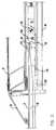
- the inventionis the vehicle-side end 8 of the ramp 6 at the end of the exhibition movement in the 1 to bring raised position. This happens according to the invention in that at the vehicle end 8 the ramp 6 by means of a joint 9 with an intermediate member 10 is connected. The intermediate member 10 in turn engages articulated to the drive 11, which the back and forth the ramp and subsequently lifting it on End of the exhibition movement.
- the ramp 6is essentially aligned with the ramp housing 4 and, as a comparison of the two levels 2 and 7 shows, far below the Floor levels to be reached 2.
- the cover 5was by the extension movement of the Ramp 6 is partially open and lies on surface 7 ramp 6.
- the movement of the ramp 6is by a Thrust element 11 accomplished that on the intermediate member 10, with which it is, for example, by means of a bolt 12 is articulated, presses.
- the thrust element 10in turn passes this pressure over the eccentrically arranged Joint 9 continues on ramp 6.
- the intermediate member 10also has bolts or protrusions 13, in the position shown in Fig. 2 no task fulfill. However, if the ramp 6 is from the position shown in FIG Extended position shown, the bolts arrive 13 in the area of a guide 14, the side, preferred arranged on both sides of the ramp housing 4 is.
- the bolts 13arrive at the end of the extension movement Ramp 6 in the area of the bend 15 of the guide 14 where the pin axis is practically fixed because of the thrust F no component in the direction of the vertical Guide section 16 has. Due to the difference in height between the axis of the bolt 13 and the position of the As a result, axes of the joints 12 and 9 occur Rotational movement of the intermediate member 10 around the fixed position of the bolt 13 until the Position shown in Fig. 1 is reached.
- This position shown in Fig. 1has the further great advantage that when loading the ramp, for example when Run over by a wheelchair, a self-locking effect occurs because the axis of the joint 9 closer to the vehicle lies as the axis of the joint 12, so that under influence a link acting vertically downward 10 is loaded clockwise and thus fixed remains, even if there is no pressure force from the drive on the Drive piece 11 acts.
- the inventionis not based on the illustrated embodiment limited, but can be modified in various ways become. So it is possible to flap 5 waive, or to design it differently, it can instead of the bolt 13, a roller construction is provided to reduce friction.
- the push element 11can also be configured differently, in the present case it also has a Guide roller 20 to a defined direction of the Thrust F (Fig. 4) to come.
Landscapes
- Health & Medical Sciences (AREA)
- Public Health (AREA)
- Life Sciences & Earth Sciences (AREA)
- Animal Behavior & Ethology (AREA)
- General Health & Medical Sciences (AREA)
- Veterinary Medicine (AREA)
- Vehicle Step Arrangements And Article Storage (AREA)
Abstract
Description
Translated fromGermanDie Erfindung betrifft eine Rampe, die aus einem Fahrzeug,insbesondere einem Autobus oder einer Straßenbahn, imBereich eine Einstieges ausfahrbar ist und es insbesondereälteren Personen oder Rollstuhlbenützern erleichtert, dasFahrzeug zu besteigen bzw. zu verlassen.The invention relates to a ramp consisting of a vehicle,especially a bus or tram, inArea an entry is extendable and it in particularelderly or wheelchair users, theGet on or off the vehicle.
Derartige Vorrichtungen sind verschiedentlich bekanntgeworden,insbesondere aus der DE 43 30 638 A. Es müssenderartige Vorrichtungen eine Reihe von Anforderungenerfüllen, die zum Teil kontradiktorisch sind und in ihrerGesamtheit bis jetzt nicht wirklich zufriedenstellenderfüllt werden konnten.Such devices have become known variouslyin particular from DE 43 30 638 A. It mustsuch devices meet a number of requirementsfulfill, which are partly adversarial and in theirsSo far, the whole has not been really satisfactorycould be fulfilled.
Eine dieser Forderungen ist, daß die Rampe eine Steigungvon höchstens 15 % aufweist. Da auch moderne Niederflurautobusse,die während des Ein- und Aussteigens von Fahrgästendie Türseite absenken, ihr Fußbodenniveau im Türbereichin einer Höhe von etwa 25 cm haben, bedingt dieseine entsprechend lange Rampe. Die Rampenlänge wiederumkann einerseits aus mechanischen Gründen, andererseitswegen Probleme bei der Unterbringung im eingezogenenZustand unterhalb des Fahrzeugbodens nicht beliebig langegewählt werden, sondern kann höchstens etwa 1,30 Meterlang sein, wodurch diese beiden Vorgaben kaum erfüllbarsind, doch behilft man sich durch die Annahme eines insolchen Fällen vorhandenen Gehsteiges, der den Höhenunterschiedentsprechend reduziert.One of these requirements is that the ramp has an inclineof at most 15%. Since modern low-floor buses,the while boarding and alighting passengerslower the door side, your floor level in the door areaat a height of about 25 cm, this is the reasona correspondingly long ramp. The ramp length in turncan on the one hand for mechanical reasons, on the other handdue to problems with housing in the confiscatedCondition underneath the vehicle floor is not indefinitelycan be selected, but can be at most about 1.30 metersbe long, which means that these two requirements can hardly be metare, but you help yourself by adopting an inin such cases existing sidewalk, the difference in heightreduced accordingly.
Problematischer ist der Übergang zwischen der Rampe unddem Fahrzeug, da ja die Rampe unterhalb des Fahrzeugbodensangeordnet ist und auch nach dem Ausfahren der Rampe dasfahrzeugseitige Ende unterhalb des Fußbodenniveaus imFahrzeuginneren bleibt. Man hat versucht, durch Übergangslippenoder ähnliche schwenkbare Bauteile zumindest dieStufe zu "entschärfen" und durch eine kurze Zwischenrampe zu ersetzen, doch ist dies nicht befriedigend. Dieeingangs genannte DE-A sieht vor, daß die Rampe am Endeihrer Ausstellbewegung mit ihrem fahrzeugseitigen Endeangehoben wird und so einen stufenlosen Übergang ins Fahrzeuginneregewährleistet. Nachteilig dabei ist allerdings,daß das Hochschwenken am Ende der Ausfahrbewegung mittelseines eigenen Antriebes erfolgen muß, auch wenn dieser inder Druckschrift nicht erwähnt wird, so ist er doch ausden tatsächlichen Ausführungen bekannt.The transition between the ramp and is more problematicthe vehicle, since the ramp is below the vehicle flooris arranged and that even after extending the rampvehicle end below the floor level in theVehicle interior remains. Tried through transition lipsor similar pivotable components at least the"Disarm" level and through a short intermediate rampto replace, but this is not satisfactory. TheDE-A initially mentioned provides that the ramp at the endtheir exhibiting movement with their vehicle endis raised and so a smooth transition into the vehicle interiorguaranteed. However, the disadvantage isthat the swiveling means at the end of the extension movementmust have its own drive, even if this inthe publication is not mentioned, it is after allthe actual designs known.
Es ist demgegenüber das Ziel der Erfindung, eine ausfahrbareRampe der eingangs definierten Art zu schaffen, beider die verbleibende fahrzeugseitige Endstufe zwischenRampe und Fahrzeugboden zumindest im wesentlichen vermiedenwird, ohne daß dazu ein zusätzlicher Antrieb oder einezusätzliche Verriegelung vorgesehen werden muß.In contrast, the aim of the invention is an extendableTo create a ramp of the type defined at the beginningthe remaining on-board power amplifier betweenRamp and vehicle floor at least substantially avoidedwithout an additional drive oradditional locking must be provided.
Erfindungsgemäß werden diese Ziele dadurch erreicht,
Die Erfindung wird im folgenden an Hand der Zeichnungnäher erläutert. Dabei zeigt
Wie aus Fig. 1 hervorgeht, befindet sich im Randbereicheines Fahrzeuges, dessen Fahrzeugrahmen nicht näher eingezeichnetist, ein Fußboden 1 mit einer Oberfläche 2. Üblicherweiseist im Randbereich eines solchen Fußbodens imTürabschnitt des Fahrzeuges eine Fußbodentragkonstruktion3 vorgesehen, die die mechanische Stabilität des Fußbodensgewährleistet. Unterhalb des Fahrzeugfußbodens ist ineinem solchen Bereich, wenn eine ausfahrbare Rampe vorgesehenist, ein Rampengehäuse 4 angebracht. Im vorliegendenFall ist dieses Rampengehäuse unbeweglich mit dem Fahrzeugrahmenund somit auch unbeweglich gegenüber dem Rahmen3 angeordnet.As is apparent from Fig. 1, is located in the edge areaof a vehicle whose vehicle frame is not shownis a floor 1 with a surface 2. Usuallyis in the edge area of such a floor inDoor section of the vehicle has a
Bei der in Fig. 3 dargestellten eingezogenen Lage derRampe, die ausgefahrene Lage ist strichliert dargestellt,erkennt man, daß eine federbelastete Klappe 5 die Öffnungdes Rahmengehäuses 4 auf der Seite des Fahrzeuges unterhalbdes Türbereiches abschließt. Dadurch wird einerseitsdas Eindringen von Schmutz, Wasser, Schnee u.dgl. verhindert,andererseits ermöglicht beispielsweise die Kontrolleder Lage der Klappe 5 eine Rückmeldung betreffend dasvollständige Einziehen der Rampe und somit die Betriebsbereitschaftdes Fahrzeuges.In the retracted position shown in FIGRamp, the extended position is shown in dashed lines,can be seen that a spring-loaded
Wie aus der strichlierten Lage der Klappe 5 in Fig. 5 inFig. 3 und auch aus der Fig. 1 ersichtlich ist, dient dieKlappe 5 auch dazu, den Übergang vom Fahrzeugfußboden 1zur Rampe 6 bzw. deren Oberfläche 7 so störungs- und stufenfreiwie möglich zu gestalten.As from the dashed position of the
Dabei liegt die Erfindung darin, das fahrzeugseitige Ende8 der Rampe 6 am Ende der Ausstellbewegung in die inFig. 1 gezeigte angehobene Lage zu bringen. Dies geschiehterfindungsgemäß dadurch, daß am fahrzeugseitigen Ende 8die Rampe 6 mittels eines Gelenkes 9 mit einem Zwischenglied10 verbunden ist. Am Zwischenglied 10 greift wiederumgelenkig der Antrieb 11 an, der das Hin- und Herschiebender Rampe und in der Folge auch deren Anheben amEnde der Ausstellbewegung bewirkt.The invention is the vehicle-
Um diese Anhebebewegung am Ende der Ausstellbewegung besserverstehen zu können, ist in Fig. 2 die Situation knappvor dem Erreichen der vollständig ausgeschobenen Rampedargestellt: Die Rampe 6 befindet sich im wesentlichenfluchtend mit dem Rampengehäuse 4 und, wie ein Vergleichder beiden Niveaus 2 und 7 zeigt, noch weit unterhalb deszu erreichenden Fußbodenniveaus 2.To make this lifting movement better at the end of the opening movementTo be able to understand, the situation is scarce in FIGbefore reaching the fully extended rampshown: the
Die Abdeckklappe 5 wurde durch die Ausschubbewegung derRampe 6 teilweise geöffnet und liegt an der Oberfläche 7der Rampe 6 an. Die Bewegung der Rampe 6 wird durch einSchubelement 11 bewerkstelligt, das auf das Zwischenglied10, mit dem es beispielsweise mittels eines Bolzens 12gelenkig verbunden ist, drückt. Das Schubelement 10 wiederumleitet diesen Druck über das exzentrisch angeordneteGelenk 9 weiter auf die Rampe 6.The
Das Zwischenglied 10 verfügt weiters über Bolzen oder Vorsprüng13, die in der in Fig. 2 gezeigten Lage keine Aufgabeerfüllen. Wird jedoch die Rampe 6 aus der in Fig. 2gezeigten Lage weiter ausgefahren, so gelangen die Bolzen13 in den Bereich einer Führung 14, die seitlich, bevorzugtzu beiden Seiten des Rampengehäuses 4, angeordnetist.The
Die Bolzen 13 gelangen am Ende der Ausschubbewegung derRampe 6 in den Bereich des Knickes 15 der Führung 14, wo die Bolzenachse praktisch fixiert wird, da die SchubkraftF keine Komponente in Richtung des vertikalenFührungsabschnittes 16 aufweist. Zufolge des Höhenunterschiedeszwischen der Achse der Bolzen 13 und der Lage derAchsen der Gelenke 12 und 9 kommt es in der Folge zu einerDrehbewegung des Zwischengliedes 10 um die im wesentlichenfestbleibende Lage der Bolzen 13, bis diein Fig. 1 dargestellte Position erreicht ist.The
Diese in Fig. 1 gezeigte Lage hat den weiteren großen Vorteil,daß beim Belasten der Rampe, beispielsweise beimÜberfahren durch einen Rollstuhl, ein Selbsthemmeffektauftritt, da die Achse des Gelenkes 9 näher zum Fahrzeugliegt als die Achse des Gelenkes 12, so daß unter Einflußeiner vertikal nach unten wirkenden Last das Zwischenglied10 in Uhrzeigerrichtung belastet wird und somit fixiertbleibt, auch wenn keine Druckkraft vom Antrieb auf dasAntriebsstück 11 wirkt.This position shown in Fig. 1 has the further great advantagethat when loading the ramp, for example whenRun over by a wheelchair, a self-locking effectoccurs because the axis of the
Die Erfindung ist nicht auf das dargestellte Ausführungsbeispielbeschränkt, sondern kann verschiedentlich abgewandeltwerden. So ist es möglich, auf die Klappe 5 zuverzichten, oder diese anders auszugestalten, es kannstatt der Bolzen 13 eine Rollenkonstruktion vorgesehensein, um die Reibung zu vermindern.The invention is not based on the illustrated embodimentlimited, but can be modified in various waysbecome. So it is possible to flap 5waive, or to design it differently, it caninstead of the
Auch andere in der Zeichnung dargestellte, aber nicht dasWesen der Erfindung betreffende Details können selbstverständlichgeändert werden. So ist es nicht notwendig, amfahrzeugseitigen Ende 8 der Rampe 6 Rollen 17 vorzusehen,die sich entlang der Unterseite des Fahrzeugbodens entlangbewegen und im Zusammenhalt mit ortsfesten Rollen 18 imRampengehäuse 4 ein anfangs horizontales Ausschieben derRampe 6, gefolgt von einer Absenkbewegung, die auf eineSchrägfläche 19 der Rampe 6 zurückzuführen ist, zu ermöglichen.Also others shown in the drawing, but not thatDetails relating to the nature of the invention can of course be takenbe changed. So it is not necessary toto provide vehicle-
Es kann auch das Schubelement 11 anders ausgestaltet sein,im vorliegenden Fall verfügt es ebenfalls über eineFührungsrolle 20, um zu einer definierten Richtung derSchubkraft F (Fig. 4) zu kommen.The
Wesentlich ist bei der gezeigten Ausführungsform für dasFunktionieren auch, daß ein Fixierung des Bolzens 13 imgekrümmten Abschnitt 15 der Führung 14 erst dann und ineinem solchen Ausmaß erfolgt, daß die Führungsrolle 17 derRampe 6 die entsprechende Beweglichkeit besitzt, um dieDrehbewegung, die sie zwischen der Lage gemäß Fig. 2 undder Lage gemäß Fig. 1 vollführt, auch wirklich ausführenzu können.It is essential in the embodiment shown forAlso work that a fixation of the
Claims (4)
Translated fromGermanPriority Applications (1)
| Application Number | Priority Date | Filing Date | Title |
|---|---|---|---|
| EP98890022AEP0931532A1 (en) | 1998-01-28 | 1998-01-28 | Ramp for vehicles |
Applications Claiming Priority (1)
| Application Number | Priority Date | Filing Date | Title |
|---|---|---|---|
| EP98890022AEP0931532A1 (en) | 1998-01-28 | 1998-01-28 | Ramp for vehicles |
Publications (1)
| Publication Number | Publication Date |
|---|---|
| EP0931532A1true EP0931532A1 (en) | 1999-07-28 |
Family
ID=8237144
Family Applications (1)
| Application Number | Title | Priority Date | Filing Date |
|---|---|---|---|
| EP98890022AWithdrawnEP0931532A1 (en) | 1998-01-28 | 1998-01-28 | Ramp for vehicles |
Country Status (1)
| Country | Link |
|---|---|
| EP (1) | EP0931532A1 (en) |
Cited By (9)
| Publication number | Priority date | Publication date | Assignee | Title |
|---|---|---|---|---|
| WO2002002043A1 (en) | 2000-07-05 | 2002-01-10 | Metalic Sa | Motorised telescopic access ramp for public transport vehicles |
| EP1121920A3 (en)* | 2000-01-31 | 2002-10-30 | S.A. Masats | Retractable ramp suitable for motor vehicles |
| EP1166739A3 (en)* | 2000-06-21 | 2003-04-02 | ROLLON S.p.A. | Foldaway ramp for disabled people in wheelchairs and children's pushchairs for low floor vehicles |
| WO2003103558A1 (en)* | 2002-06-11 | 2003-12-18 | Fine Products, S.A. | Vehicle access ramp |
| FR2944955A1 (en)* | 2009-04-29 | 2010-11-05 | Metalic | Ramp for accessing public vehicle, for e.g. mobility impaired person, has panel that is mobile between storage position and utilization position, where rear edge of panel is placed in continuity to vehicle under action of operating units |
| DE202012000642U1 (en) | 2012-01-23 | 2012-02-27 | Policske Strojirny A.S. | Entry lift for means of transport with lateral driveway for a wheelchair |
| US20140044512A1 (en)* | 2011-03-14 | 2014-02-13 | Wally Couto | Ramp system |
| WO2019096927A1 (en)* | 2017-11-16 | 2019-05-23 | Knorr-Bremse Gesellschaft Mit Beschränkter Haftung | Tread device for a retractable step access system for a vehicle, and retractable step access system with a tread device |
| FR3122988A1 (en)* | 2021-05-19 | 2022-11-25 | Stepconcept | Retractable vehicle access device |
Citations (4)
| Publication number | Priority date | Publication date | Assignee | Title |
|---|---|---|---|---|
| DE4134559A1 (en)* | 1991-10-19 | 1993-04-29 | Daimler Benz Ag | Ramp for wheelchair access to doorway of vehicle - is raised by electric motor and threaded spindle into position ensuring stepless transition on to floor |
| EP0578574A1 (en)* | 1992-07-10 | 1994-01-12 | Gec Alsthom Transport Sa | Improved access device for a rail vehicle |
| DE4316948C1 (en)* | 1993-05-21 | 1994-05-05 | Daimler Benz Ag | Extensible wheelchair loading ramp for bus - has stop limiting downwards hinging movement of link between it and thruster and pin on link engaged by shutter |
| DE4330638A1 (en) | 1993-09-10 | 1995-03-16 | Mbb Foerder & Hebesysteme | Device to permit trouble-free movement onto and over a ramp |
- 1998
- 1998-01-28EPEP98890022Apatent/EP0931532A1/ennot_activeWithdrawn
Patent Citations (4)
| Publication number | Priority date | Publication date | Assignee | Title |
|---|---|---|---|---|
| DE4134559A1 (en)* | 1991-10-19 | 1993-04-29 | Daimler Benz Ag | Ramp for wheelchair access to doorway of vehicle - is raised by electric motor and threaded spindle into position ensuring stepless transition on to floor |
| EP0578574A1 (en)* | 1992-07-10 | 1994-01-12 | Gec Alsthom Transport Sa | Improved access device for a rail vehicle |
| DE4316948C1 (en)* | 1993-05-21 | 1994-05-05 | Daimler Benz Ag | Extensible wheelchair loading ramp for bus - has stop limiting downwards hinging movement of link between it and thruster and pin on link engaged by shutter |
| DE4330638A1 (en) | 1993-09-10 | 1995-03-16 | Mbb Foerder & Hebesysteme | Device to permit trouble-free movement onto and over a ramp |
Cited By (13)
| Publication number | Priority date | Publication date | Assignee | Title |
|---|---|---|---|---|
| EP1121920A3 (en)* | 2000-01-31 | 2002-10-30 | S.A. Masats | Retractable ramp suitable for motor vehicles |
| ES2187314A1 (en)* | 2000-01-31 | 2003-06-01 | Masats Sa | Retractable ramp suitable for motor vehicles |
| EP1166739A3 (en)* | 2000-06-21 | 2003-04-02 | ROLLON S.p.A. | Foldaway ramp for disabled people in wheelchairs and children's pushchairs for low floor vehicles |
| WO2002002043A1 (en) | 2000-07-05 | 2002-01-10 | Metalic Sa | Motorised telescopic access ramp for public transport vehicles |
| FR2811223A1 (en)* | 2000-07-05 | 2002-01-11 | Metalic | MOTORIZED TELESCOPIC ACCESS RAMP FOR PUBLIC TRANSPORT VEHICLES |
| ES2200691A1 (en)* | 2002-06-11 | 2004-03-01 | Fine Productos S A | Vehicle access ramp |
| WO2003103558A1 (en)* | 2002-06-11 | 2003-12-18 | Fine Products, S.A. | Vehicle access ramp |
| FR2944955A1 (en)* | 2009-04-29 | 2010-11-05 | Metalic | Ramp for accessing public vehicle, for e.g. mobility impaired person, has panel that is mobile between storage position and utilization position, where rear edge of panel is placed in continuity to vehicle under action of operating units |
| US20140044512A1 (en)* | 2011-03-14 | 2014-02-13 | Wally Couto | Ramp system |
| DE202012000642U1 (en) | 2012-01-23 | 2012-02-27 | Policske Strojirny A.S. | Entry lift for means of transport with lateral driveway for a wheelchair |
| WO2019096927A1 (en)* | 2017-11-16 | 2019-05-23 | Knorr-Bremse Gesellschaft Mit Beschränkter Haftung | Tread device for a retractable step access system for a vehicle, and retractable step access system with a tread device |
| US11338738B2 (en) | 2017-11-16 | 2022-05-24 | Knorr-Bremse Gesellschaft Mit Beschränkter Haftung | Tread device for a retractable step access system for a vehicle, and retractable step access system with a tread device |
| FR3122988A1 (en)* | 2021-05-19 | 2022-11-25 | Stepconcept | Retractable vehicle access device |
Similar Documents
| Publication | Publication Date | Title |
|---|---|---|
| AT500017B1 (en) | SWIVEL SLIDING DOOR FOR VEHICLES | |
| CH621976A5 (en) | ||
| EP2627537A1 (en) | Ramp having a side barrier | |
| EP3900982A1 (en) | Access system with accessible sealing flap | |
| EP3663158B1 (en) | Sliding plug door with step system for a vehicle | |
| EP0931532A1 (en) | Ramp for vehicles | |
| EP3213973B1 (en) | Entry system for a vehicle | |
| EP3684667B1 (en) | Rail vehicle having a movable floor part at a door opening | |
| DE19725677C2 (en) | Window or door on caravans, mobile homes or other vehicles, with locking devices with a common operating handle | |
| DE102016201275B3 (en) | Frontnotausstieg | |
| EP1857085A2 (en) | Retractable ramp for vehicles in public urban and long-distance passenger transport networks | |
| EP3709945B1 (en) | Tread device for a retractable step access system for a vehicle, and retractable step access system with a tread device | |
| EP1743611B1 (en) | Extensible ramp for public service vehicles | |
| DE3401390C2 (en) | Sliding door for vehicles or the like | |
| EP2433835B1 (en) | Loading bar for setting and adjusting in or on a rail in a cargo space | |
| EP2333209A1 (en) | Hinge for a cabin operating unit of a lift assembly | |
| EP0851083B1 (en) | Vertically sliding window | |
| EP0094607A2 (en) | Inclined lift for a wheel chair or the like mounted on a vehicle | |
| EP0063281A1 (en) | Device for guiding a pivotable sliding door at a vehicle cab | |
| EP1700554B1 (en) | Partition wall | |
| EP4147893A1 (en) | Pivoting sliding door with foldable door seal and vehicle | |
| DE19706338C2 (en) | security lock | |
| DE69407302T2 (en) | INDUSTRIAL DOOR | |
| DE102011005238B4 (en) | Lockable ramp | |
| DE3719896C1 (en) | Partition wall |
Legal Events
| Date | Code | Title | Description |
|---|---|---|---|
| PUAI | Public reference made under article 153(3) epc to a published international application that has entered the european phase | Free format text:ORIGINAL CODE: 0009012 | |
| AK | Designated contracting states | Kind code of ref document:A1 Designated state(s):AT DE ES FR GB IT | |
| 17P | Request for examination filed | Effective date:20000128 | |
| AKX | Designation fees paid | Free format text:AT DE ES FR GB IT | |
| 17Q | First examination report despatched | Effective date:20030502 | |
| RAP1 | Party data changed (applicant data changed or rights of an application transferred) | Owner name:KNORR-BREMSE GESELLSCHAFT MIT BESCHRAENKTER HAFTUN | |
| STAA | Information on the status of an ep patent application or granted ep patent | Free format text:STATUS: THE APPLICATION IS DEEMED TO BE WITHDRAWN | |
| 18D | Application deemed to be withdrawn | Effective date:20030913 |