EP0931513B1 - Reaming system for oblong acetabular component - Google Patents
Reaming system for oblong acetabular componentDownload PDFInfo
- Publication number
- EP0931513B1 EP0931513B1EP99300326AEP99300326AEP0931513B1EP 0931513 B1EP0931513 B1EP 0931513B1EP 99300326 AEP99300326 AEP 99300326AEP 99300326 AEP99300326 AEP 99300326AEP 0931513 B1EP0931513 B1EP 0931513B1
- Authority
- EP
- European Patent Office
- Prior art keywords
- bearing plate
- cavity
- drive member
- reamer
- handle
- Prior art date
- Legal status (The legal status is an assumption and is not a legal conclusion. Google has not performed a legal analysis and makes no representation as to the accuracy of the status listed.)
- Expired - Lifetime
Links
- 230000013011matingEffects0.000claimsdescription16
- 230000007246mechanismEffects0.000claimsdescription15
- 230000008878couplingEffects0.000claimsdescription5
- 238000010168coupling processMethods0.000claimsdescription5
- 238000005859coupling reactionMethods0.000claimsdescription5
- 238000003780insertionMethods0.000claimsdescription2
- 230000037431insertionEffects0.000claimsdescription2
- 210000000588acetabulumAnatomy0.000description15
- 210000002414legAnatomy0.000description10
- 230000007547defectEffects0.000description9
- 239000007943implantSubstances0.000description8
- 230000009977dual effectEffects0.000description6
- 150000001875compoundsChemical class0.000description5
- 238000011882arthroplastyMethods0.000description4
- 210000001624hipAnatomy0.000description4
- 210000001519tissueAnatomy0.000description4
- 230000007774longtermEffects0.000description3
- 210000000988bone and boneAnatomy0.000description2
- 230000000295complement effectEffects0.000description2
- 238000000034methodMethods0.000description2
- 210000004197pelvisAnatomy0.000description2
- 230000008569processEffects0.000description2
- 238000001356surgical procedureMethods0.000description2
- 230000000007visual effectEffects0.000description2
- 206010058314DysplasiaDiseases0.000description1
- 210000003484anatomyAnatomy0.000description1
- 230000015572biosynthetic processEffects0.000description1
- 210000001513elbowAnatomy0.000description1
- 230000036541healthEffects0.000description1
- 238000002513implantationMethods0.000description1
- 210000003127kneeAnatomy0.000description1
- 210000000689upper legAnatomy0.000description1
Images


Classifications
- A—HUMAN NECESSITIES
- A61—MEDICAL OR VETERINARY SCIENCE; HYGIENE
- A61B—DIAGNOSIS; SURGERY; IDENTIFICATION
- A61B17/00—Surgical instruments, devices or methods
- A61B17/16—Instruments for performing osteoclasis; Drills or chisels for bones; Trepans
- A61B17/1662—Instruments for performing osteoclasis; Drills or chisels for bones; Trepans for particular parts of the body
- A61B17/1664—Instruments for performing osteoclasis; Drills or chisels for bones; Trepans for particular parts of the body for the hip
- A61B17/1666—Instruments for performing osteoclasis; Drills or chisels for bones; Trepans for particular parts of the body for the hip for the acetabulum
- A—HUMAN NECESSITIES
- A61—MEDICAL OR VETERINARY SCIENCE; HYGIENE
- A61F—FILTERS IMPLANTABLE INTO BLOOD VESSELS; PROSTHESES; DEVICES PROVIDING PATENCY TO, OR PREVENTING COLLAPSING OF, TUBULAR STRUCTURES OF THE BODY, e.g. STENTS; ORTHOPAEDIC, NURSING OR CONTRACEPTIVE DEVICES; FOMENTATION; TREATMENT OR PROTECTION OF EYES OR EARS; BANDAGES, DRESSINGS OR ABSORBENT PADS; FIRST-AID KITS
- A61F2/00—Filters implantable into blood vessels; Prostheses, i.e. artificial substitutes or replacements for parts of the body; Appliances for connecting them with the body; Devices providing patency to, or preventing collapsing of, tubular structures of the body, e.g. stents
- A61F2/02—Prostheses implantable into the body
- A61F2/30—Joints
- A61F2002/30001—Additional features of subject-matter classified in A61F2/28, A61F2/30 and subgroups thereof
- A61F2002/30316—The prosthesis having different structural features at different locations within the same prosthesis; Connections between prosthetic parts; Special structural features of bone or joint prostheses not otherwise provided for
- A61F2002/30329—Connections or couplings between prosthetic parts, e.g. between modular parts; Connecting elements
- A61F2002/30383—Connections or couplings between prosthetic parts, e.g. between modular parts; Connecting elements made by laterally inserting a protrusion, e.g. a rib into a complementarily-shaped groove
- A61F2002/30403—Longitudinally-oriented cooperating ribs and grooves on mating lateral surfaces of a mainly longitudinal connection
- A—HUMAN NECESSITIES
- A61—MEDICAL OR VETERINARY SCIENCE; HYGIENE
- A61F—FILTERS IMPLANTABLE INTO BLOOD VESSELS; PROSTHESES; DEVICES PROVIDING PATENCY TO, OR PREVENTING COLLAPSING OF, TUBULAR STRUCTURES OF THE BODY, e.g. STENTS; ORTHOPAEDIC, NURSING OR CONTRACEPTIVE DEVICES; FOMENTATION; TREATMENT OR PROTECTION OF EYES OR EARS; BANDAGES, DRESSINGS OR ABSORBENT PADS; FIRST-AID KITS
- A61F2/00—Filters implantable into blood vessels; Prostheses, i.e. artificial substitutes or replacements for parts of the body; Appliances for connecting them with the body; Devices providing patency to, or preventing collapsing of, tubular structures of the body, e.g. stents
- A61F2/02—Prostheses implantable into the body
- A61F2/30—Joints
- A61F2/30767—Special external or bone-contacting surface, e.g. coating for improving bone ingrowth
- A61F2/30771—Special external or bone-contacting surface, e.g. coating for improving bone ingrowth applied in original prostheses, e.g. holes or grooves
- A61F2002/30772—Apertures or holes, e.g. of circular cross section
- A61F2002/30784—Plurality of holes
- A61F2002/30787—Plurality of holes inclined obliquely with respect to each other
- A—HUMAN NECESSITIES
- A61—MEDICAL OR VETERINARY SCIENCE; HYGIENE
- A61F—FILTERS IMPLANTABLE INTO BLOOD VESSELS; PROSTHESES; DEVICES PROVIDING PATENCY TO, OR PREVENTING COLLAPSING OF, TUBULAR STRUCTURES OF THE BODY, e.g. STENTS; ORTHOPAEDIC, NURSING OR CONTRACEPTIVE DEVICES; FOMENTATION; TREATMENT OR PROTECTION OF EYES OR EARS; BANDAGES, DRESSINGS OR ABSORBENT PADS; FIRST-AID KITS
- A61F2/00—Filters implantable into blood vessels; Prostheses, i.e. artificial substitutes or replacements for parts of the body; Appliances for connecting them with the body; Devices providing patency to, or preventing collapsing of, tubular structures of the body, e.g. stents
- A61F2/02—Prostheses implantable into the body
- A61F2/30—Joints
- A61F2/32—Joints for the hip
- A61F2/34—Acetabular cups
- A61F2002/3401—Acetabular cups with radial apertures, e.g. radial bores for receiving fixation screws
- A61F2002/3403—Polar aperture
- A—HUMAN NECESSITIES
- A61—MEDICAL OR VETERINARY SCIENCE; HYGIENE
- A61F—FILTERS IMPLANTABLE INTO BLOOD VESSELS; PROSTHESES; DEVICES PROVIDING PATENCY TO, OR PREVENTING COLLAPSING OF, TUBULAR STRUCTURES OF THE BODY, e.g. STENTS; ORTHOPAEDIC, NURSING OR CONTRACEPTIVE DEVICES; FOMENTATION; TREATMENT OR PROTECTION OF EYES OR EARS; BANDAGES, DRESSINGS OR ABSORBENT PADS; FIRST-AID KITS
- A61F2/00—Filters implantable into blood vessels; Prostheses, i.e. artificial substitutes or replacements for parts of the body; Appliances for connecting them with the body; Devices providing patency to, or preventing collapsing of, tubular structures of the body, e.g. stents
- A61F2/02—Prostheses implantable into the body
- A61F2/30—Joints
- A61F2/32—Joints for the hip
- A61F2/34—Acetabular cups
- A61F2002/3453—Acetabular cups having a non-hemispherical convex outer surface, e.g. quadric-shaped
- A61F2002/3459—Acetabular cups having a non-hemispherical convex outer surface, e.g. quadric-shaped made of different partially-spherical portions
- A—HUMAN NECESSITIES
- A61—MEDICAL OR VETERINARY SCIENCE; HYGIENE
- A61F—FILTERS IMPLANTABLE INTO BLOOD VESSELS; PROSTHESES; DEVICES PROVIDING PATENCY TO, OR PREVENTING COLLAPSING OF, TUBULAR STRUCTURES OF THE BODY, e.g. STENTS; ORTHOPAEDIC, NURSING OR CONTRACEPTIVE DEVICES; FOMENTATION; TREATMENT OR PROTECTION OF EYES OR EARS; BANDAGES, DRESSINGS OR ABSORBENT PADS; FIRST-AID KITS
- A61F2220/00—Fixations or connections for prostheses classified in groups A61F2/00 - A61F2/26 or A61F2/82 or A61F9/00 or A61F11/00 or subgroups thereof
- A61F2220/0025—Connections or couplings between prosthetic parts, e.g. between modular parts; Connecting elements
Definitions
- the present inventionrelates to reaming systems and more particularly to a system for reaming bone in preparation for implanting a prosthetic component, such as an acetabular cup.
- Joint arthroplastyis a well known surgical procedure by which a diseased and/or damaged natural joint is replaced by a prosthetic joint. Joint arthroplasty is commonly performed for hips, knees, elbows, and other joints. The health and condition of the joint to be replaced dictate the type of prosthesis necessary to replace the natural joint.
- a total hip arthroplastyan acetabular cup is implanted in the acetabular cavity in the pelvis to replace the natural acetabulum. Replacement of the acetabulum is necessary for various joint conditions, such as when there is an inadequate articulation surface for a head or ball of a prosthetic femoral component.
- Total hip arthroplastyis also warranted in certain cases of Developmental Displasia Hip (DDH) where the natural acetabular cavity does not properly form to allow sufficient joint articulation.
- DDHDevelopmental Displasia Hip
- a cavityis reamed in the acetabulum.
- the acetabular cupis then inserted into the formed cavity and secured by mechanical means, interference fit, or by a combination thereof.
- the acetabular cupis positioned in the pelvis at a fixed orientation with respect to patient anatomy and should remain stable.
- an oblong acetabular cupmay need to be implanted. Such cases include joint conditions where an implanted acetabular cup (typically a hemispherical cup) has migrated in a superior direction and certain DDH cases.
- the oblong geometry of the cupcompensates for the elongated acetabular cavity.
- One type of elongated acetabular cuphas an outer contour defined by two adjacent hemispheres.
- An exemplary dual hemisphere acetabular cup 10is shown in FIGS. 1A and 1B.
- the cup 10has an outer surface 12 defined by a first primary hemisphere 14 merged with a secondary hemisphere 16.
- the primary hemispheredefines a primary face 18 and the secondary hemisphere defines a secondary face 19.
- the primary hemisphere 14has a concave inner surface 17 adapted for receiving the liner capable of receiving head or ball of a femoral component.
- the cavity in the acetabulumis typically formed in two discrete stages.
- the true (also known as primary or natural) acetabular cavityis formed.
- a surgeonaligns a conventional reamer/driver instrument with the acetabulum and reams the primary or natural acetabular cavity to a hemispherical shape.
- FIG. 2shows an illustrative prior art reamer/driver instrument 20 for reaming the natural acetabular cavity 22 in the acetabulum 24.
- Forming the natural acetabular cavity with the reamer/driver instrument 20is a relatively straight forward process.
- the already formed natural cavity 22should be used as a reference point to provide a cavity that matches the outer surface 12 of the oblong cup 10.
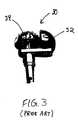
- FIG. 3shows one type of prior art instrument, known as a basket reamer/driver 30, used to form the false acetabular cavity after reaming the true acetabular cavity.
- reamer/driverrefers to an instrument as a whole, while reamer refers to the rotating head for removing tissue.
- the device 30includes an arcuate guide 32 for placement in the reamed natural cavity and a reamer 34 for removing bony tissue.
- the reamer 34is matable with a power drill mechanism for rotating the reamer.
- a similar deviceis shown in US 5290315.
- the surgeonfirst visually identifies the location where the false cavity is to be formed.
- the false or defect cavitywill be somewhere about the periphery of the natural acetabular cavity 22 (FIG. 2).
- the surgeonrolls the reamer 34 in a direction toward the area to be reamed to form the false acetabular cavity.
- the present inventionprovides a reaming system for precise formation of a cavity having a compound geometric shape. Although the invention is primarily shown and described in conjunction with reaming an acetabulum for implanting an oblong acetabular cup, it is understood that the invention has other applications as well.
- the reaming systemis particularly useful in forming a second cavity in the acetabulum in relation to a first cavity for implantation of an acetabular cup with a dual hemisphere outer surface.
- the reaming systemincludes a reamer/driver instrument with a bearing plate having a first portion coupled to the distal end of a handle and a second portion coupled to an elongate drive member. A proximal end of the handle facilitates positioning of the instrument.
- the drive memberhas a distal reamer mating end and a proximal end for coupling with a mechanism to rotate the distal reamer mating end of the drive member.
- the distal reamer mating endis axially movable toward and away from a distal surface of the bearing plate to form the second cavity.
- the systemfurther includes at least one locator member removably and replaceably mountable to the distal surface of the bearing plate for positioning the distal reamer mating end in relation to the already formed first cavity.
- the systemincludes a plurality of reamers each having different outer dimensions and an inner surface matable with the distal reamer mating end of the single drive member.
- the reamers and drive memberprovide a modular reaming system allowing incremental increases in the size of the cavity by sequentially attaching reamers of increasing outer dimensions to the drive member.
- the reaming systemincludes a plurality of locator members each having a geometry corresponding to a particular size reamer.
- each of the locator membershas a base portion matable to a bearing plate and an upper portion with an outer surface, at least part of which forms a part of a sphere. The arcuate outer surface is adapted for placement within the hemispherical inner surface of the already formed first cavity.
- Each locator memberhas a geometry that is effective to position a particular reamer such that the second cavity is formed to complement a corresponding portion of the oblong acetabular cup to be implanted.
- the systemincludes a guide member that is securable to the handle to provide an indication of the abduction and anteversion angle of the drive member in relation to the patient.
- the guide memberhas a leg portion with first and second arm portions extending from one end of the leg portion. The other end of the leg portion is matable with the handle such that the guide member is rotatable about the longitudinal axis of the handle. The orientation of the leg and arm portions of the guide member in relation to the patient provides a visual indication of the respective abduction and anteversion angles at which the second cavity will be reamed.
- the instrumentis assembled by selecting a reamer to form a second cavity of desired size and securing the reamer to the distal reamer mating end of the drive member. A corresponding locator member is then affixed to the bearing plate. The guide member is mated to the handle and the proximal end of the drive member is coupled to a drill mechanism.
- the locator memberis positioned in the already formed first cavity.
- the guide memberprovides a visual indication of the abduction and anteversion position of the instrument in relation to the patient.
- the abduction angleis measured with respect to the transverse plane which divides the body into superior and inferior portions.
- the anteversion angleis measured with respect to the coronal or frontal plane to form a boundary between anterior and posterior portions of the body.
- the instrumentis positioned at a predetermined abduction angle when the leg portion of the guide member is vertical as the patient lay horizontally.
- the instrumentis positioned at a predetermined anteversion angle when the longitudinal axis of the drive member is aligned with a tip of either the first or second arm portions of the guide member.
- the location at which the second or defect cavity is to be formedis then determined by the surgeon.
- the instrumentis rotated about the first or true acetabular cavity (with the locator member in the first cavity) while maintaining the abduction and anteversion orientation of the instrument.
- the guide memberis rotatable about the longitudinal axis of the handle to facilitate positioning of the instrument to ream the second cavity while maintaining the alignment of the face of the primary hemisphere of the implant.
- the drive memberis moved axially in a direction away from the bearing plate for removing tissue to form the defect cavity.
- a compound geometry cavityis thereby precisely formed in the acetabulum for receiving a dual hemisphere acetabular component.
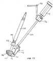
- FIGS. 4A-11illustrate an exemplary reaming system 100 including an instrument 102 having a drive member 104 matable with a reamer 106 and an elongate handle 108 coupled to a bearing plate 110.
- a locator member 113extends from the bearing plate 110 for insertion into an already formed cavity to position the instrument 102.
- the reaming system 100is particularly useful in forming a false or defect acetabular cavity in the acetabulum 24 in relation to an already formed primary cavity 22 for implanting an oblong acetabular cup 10 (FIG. 1).
- the handle 108has a proximal end 112 with a hand grip 114 to facilitate positioning of the instrument 102.
- a distal end 116 of the handleis secured to a first portion 118 of the bearing plate.
- the handle 108can be coupled to the bearing plate 110 using a variety of engagement mechanisms that can provide releasable or permanent engagement, and combinations thereof.
- the distal end 116 of the handleis insertable into a bore 120 (FIG. 8) formed in a handle engaging portion 122 extending from a proximal surface 124 of the bearing plate. Threads 126 formed on the distal end 116 of the handle are engageable with threads 128 formed on the inner surface of the bore for threadably engaging the handle 108 to the bearing plate 110.
- the bearing plate 110has a second portion 130 with a drive member guide portion 132 extending from the proximal surface 124 of the bearing plate.
- a bore 134(FIG. 8) extends through the drive member guide portion 132 with a bearing 136 (FIG. 10) disposed at least partly within the bore.
- the drive member guide portion 132 and bearing 136secure the drive member 104 at a fixed angle with respect to the handle 108 while allowing axial and rotational movement of the drive member with respect to the bearing plate 110.
- the second portion 130 of the bearing plateextends from the first portion 118 at an angle A.
- the angled bearing plate 110positions the handle 108 and drive member 104 at angle A. This angle corresponds to the angle formed by the primary and secondary faces of the acetabular component, as described below.
- the angle A of the bearing plate first and second portions 118,130can vary from about zero to about forty-five degrees, and more preferably from about fifteen degrees to about twenty degrees.
- the drive member 104has a distal reamer mating end 136 that extends from a distal surface 138 of the bearing plate.
- the reamer 106is selectively matable to the distal end 136 such that the reamer can be quickly engaged and released from the drive member 104.
- the distal reamer mating end 136terminates in an annular mounting plate 140 that is readily engagable with the reamer 106.
- the reamer 106is mounted on the plate 140 by applying axial pressure and released by actuating a biased release switch 142 (FIG. 8). It is understood, however, that one of ordinary skill in the art can readily modify the reamer mating mechanism 140,142 described herein.
- a collar 144is affixed to the drive member 104 at a predetermined distance from the tip of the distal reamer mating end 136.
- the collar 144is effective to limit axial movement of the distal reamer mating end 136 in a direction away from the distal surface 138 of the bearing plate. More particularly, at maximum extension of the reamer 106 (FIG. 4B) the collar 144 abuts the drive member guide portion 132 of the bearing plate. At full retraction of the reamer 106 (FIG. 4A), the collar 144 is located at a selected distance from the drive member guide portion 132 and the distal reamer mating end 136 of the drive member is adjacent the bearing plate 110.
- the proximal end 146 of the drive memberis adapted for coupling with a conventional drill mechanism (not shown) to rotate the drive member 104 and reamer 106.
- a conventional drill mechanism(not shown) to rotate the drive member 104 and reamer 106.
- drill mechanismsare well known to one of ordinary skill in the art.
- the drive member 104can include various components to enable rotation and distal extension of the reamer 106 while maintaining the drive member at a fixed angle relative to the bearing plate 110 and the handle 108.
- the drive member 104includes an inner member 148 that is rotable within a concentric outer member 150.
- the locator member 113has a base portion 152 that is matable to the distal surface 138 of the bearing plate 110 and an upper portion 154 with an outer surface 156 shaped to complement the formed true acetabular cavity. As described in further detail below, the locator member 113 positions the reamer 106 such that the false acetabular cavity is formed by referencing the location of the already formed by true acetabular cavity.
- the outer surface 156 of the locator memberforms a portion of a sphere that complements the spherical cavity formed the reamer 106.
- the longitudinal axis of the handle 108is aligned with the center of the spherical shape partially formed by the outer surface 156 of the locator member.
- the upper portion 154 of the locator memberalso includes an arcuate inner surface 157.
- the inner surface 157is generally concave such that the locator member 113 does not interfere with the reamer 106. It is important that the reamer 106 be axially extendable from the bearing plate 110 without contacting the locator member 113.
- the inner surface 157should be dimensioned to provide adequate spacing from the reamer 106 to allow removed tissue to escape from the rotating reamer.
- the base portion 152 of the locator memberhas an end surface 158 with first and second posts 160a,b (FIG. 11) extending therefrom.
- the posts 160are insertable within corresponding first and second bores 162 formed in the first portion 118 of the bearing plate 110.
- the posts 160are precisely located to position the outer surface 156 of the locator member in relation to the drive member 104 and reamer 106.
- the locator member 113can be secured to the bearing plate 110 with a variety of attachment mechanisms. Exemplary mechanisms include fasteners such as nuts, bolts, screws, interference fit dimensions and other detachable mechanisms. In the exemplary embodiment shown, the locator member 113 is securable to the bearing plate with a retaining screw 164 passing through an aperture in the bearing plate 110 into a corresponding threaded bore 165 in the locator member 113.
- the reaming system 100can also include a guide mechanism 166 for providing anteversion and abduction information to an operator.
- the guide mechanism 166has a guide member 168 with a leg 170 and first and second arms 172a,b forming a V-shape. As shown, the arms 172 are perpendicular to the leg portion 170.
- a distal end 174 of the legis insertable into a bore formed in an alignment block 176 coupled to the handle 108.
- the alignment block 176is rotatable about a longitudinal axis of the handle 108 when positioning the reamer to form the defect cavity, as described below.
- the bore in the alignment block 176is formed such that the leg 170 extends from the alignment block to form an angle C (FIG. 5A) of about one hundred and thirty-five degrees with respect to the handle.
- the exemplary desired abduction angleis achieved.
- the abduction angleis determined with respect to the midline transverse plane.
- the first and second arms 172a,b of the guideform an exemplary angle D of about forty degrees.
- the angle Dis bifurcated into two twenty degree sections to provide an anteversion angle of about twenty degrees when forming the false acetabular cavity.
- the anteversion angleis measure with respect to the coronal or frontal plane.
- the arms 172serve as guides for the operator when orienting the reamer/driver. More particularly, the drive member 104 is axially aligned with an end of one of the arms 172 to provide about twenty degrees of anteversion when forming the false acetabular cavity.
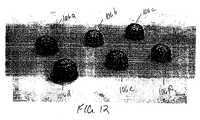
- the reaming system 100 of the present inventionincludes a series of different sized reamers 106a-f to provide a modular system.
- Each of the reamers 106has outer dimensions for reaming a particular sized cavity.
- the reaming system 100requires a single reamer/driver instrument 102 that is matable to each of the reamers 106.
- the reamer/driveris not limited to forming a certain size cavity, as in prior art reaming devices.
- the system 100can also include a series of locator members 113a,b differing in size. Although two locator members 113 are shown, it is understood that the system can include any number of reamers and locator members.
- Each locator member 113corresponds to a particular size acetabular component to be implanted and/or reamer 106 to be used to form the false acetabular cavity. As the dual hemisphere acetabular component increases in size, the corresponding locator member 113 also increases in size to position the reamer 106 to the desired location. That is, for each size acetabular cup implant, the corresponding locator member 113 provides a reference point for forming the false acetabular cavity in relation to the reamed true acetabular cavity.
- the collar 144does not need to be adjusted for each reamer or acetabular cup.
- the locator members 113are formed such that the maximum reamer extension determined by the collar 144 corresponds to the depth desired for the selected reamer and acetabular cup.
- the overall dimensions for reamer/driver and various componentscan vary to achieve a desired geometry for the natural and defect cavities to conform to the outer surface of a particular acetabular component. It is understood that one of ordinary skill in the art can readily modify the exemplary shape and dimensions described herein.
- Illustrative radii for the outer surface of the reamers 106include 45, 48, 51, 54, 57, 60, and 63 millimeters.
- the corresponding locator members 113have a spherical outer surface 156 formed by a radius that can range from about 20 millimeters to about 40 millimeters.
- the dual geometry acetabular cavityis prepared to receive the acetabular component in an exemplary sequence of steps.
- the acetabular area of the patientis first evaluated using X-rays to determine the acetabular configuration and to reveal any anatomical anomaly, dysplasia, and/or leg-length discrepancy. Preoperative templating can then be performed to determine the size of the acetabular component to be implanted.
- acetabular cavity 22is formed in the acetabulum 24 (FIG. 2). This cavity is reamed using a conventional reamer/driver instrument 20 well known to one of ordinary skill in the art.
- the formed natural acetabular cavity 22has a hemispherical shape for receiving a corresponding primary portion of the oblong acetabular cup.
- the false or defect acetabulum cavityis formed using the reaming system 100 of the present invention.
- the false acetabular cavitycorresponds to the secondary or elongated portion 16 of the oblong acetabular implant 10 (FIG. 1).
- the false acetabular cavityshould be positioned in relation to the already reamed natural acetabular cavity and formed within precise dimensional tolerances. Proper location and geometry of the false acetabular cavity provide a secure interference fit for the implant to allow long term fixation of the implanted acetabular cup.
- a corresponding reamer 106 and locator 113are selected and secured to the instrument 102, as described above. The location of the false acetabular cavity to be formed is then visually determined by the surgeon.
- the orientation of the true acetabular cavitymust be formed such that the primary portion 14 of the acetabular cup is properly aligned to receive the head of the femoral component.
- the acetabular cup 10should be implanted to provide optimal range of motion for the femur of the patient and to reflect anatomical joint articulation to the extent possible:
- the false acetabular cavityshould be formed to receive the secondary portion 16 of the oblong acetabular cup by referencing the true acetabular cavity.
- the instrument 102is positioned in relation to the already formed natural acetabular cavity by placing the locator member 113 within the formed natural acetabular cavity 22.
- the instrumentis manipulated to a position of about forty-five degrees abduction and about twenty degrees anteversion. More particularly, the leg member 170 of the guide should extend vertically (FIG. 5A) and the first or second arm 172a,b of the guide should be aligned with the longitudinal axis of the drive member 104 (FIG. 7).
- the handle 104While maintaining the desired anteversion and abduction orientation, the handle 104 is rotated about the true acetabular cavity until the reamer 106 is aligned with the desired location for the false acetabular cavity.
- the alignment block 176rotates about the handle 108 to allow the anteversion/abduction orientation to be maintained, i.e., to retain the orientation of the primary face of the oblong implant.
- the spherical outer surface 156 of the locator membereasily rotates in the formed spherical natural acetabular cavity to provide a reference point for reaming the false acetabular cavity.
- the instrument 102has the desired anteversion and abduction orientation and the reamer 106 is aligned with the location of the false acetabular cavity to be formed.
- the drive mechanism(not shown) is then activated to rotate the drive member 104 and reamer 106.
- the operatorapplies axial pressure to the drive member 104 to cause the reamer 104 to extend in a distal direction along the longitudinal axis of the drive member, i.e., away from the bearing plate 110.
- the anteversion/abduction position of the instrument 102is maintained during the reaming process.
- the reamer 106continues to extend distally until the collar 144 contacts the drive member guide portion 132 of the bearing plate.
- the plunger-type movement of the reamer 106forms a false acetabular cavity with a precise depth and contour.
- the compound geometry cavityis then evaluated using a oblong trial implant and the acetabular cup is inserted into the formed cavity using known surgical procedures.
Landscapes
- Health & Medical Sciences (AREA)
- Surgery (AREA)
- Life Sciences & Earth Sciences (AREA)
- Biomedical Technology (AREA)
- Medical Informatics (AREA)
- Orthopedic Medicine & Surgery (AREA)
- Oral & Maxillofacial Surgery (AREA)
- Engineering & Computer Science (AREA)
- Dentistry (AREA)
- Heart & Thoracic Surgery (AREA)
- Nuclear Medicine, Radiotherapy & Molecular Imaging (AREA)
- Molecular Biology (AREA)
- Animal Behavior & Ethology (AREA)
- General Health & Medical Sciences (AREA)
- Public Health (AREA)
- Veterinary Medicine (AREA)
- Prostheses (AREA)
- Milling, Broaching, Filing, Reaming, And Others (AREA)
- Surgical Instruments (AREA)
Description
- The present invention relates to reaming systems and more particularly to asystem for reaming bone in preparation for implanting a prosthetic component, suchas an acetabular cup.
- Joint arthroplasty is a well known surgical procedure by which a diseasedand/or damaged natural joint is replaced by a prosthetic joint. Joint arthroplasty iscommonly performed for hips, knees, elbows, and other joints. The health andcondition of the joint to be replaced dictate the type of prosthesis necessary toreplace the natural joint.
- In a total hip arthroplasty an acetabular cup is implanted in the acetabularcavity in the pelvis to replace the natural acetabulum. Replacement of theacetabulum is necessary for various joint conditions, such as when there is aninadequate articulation surface for a head or ball of a prosthetic femoral component.Total hip arthroplasty is also warranted in certain cases of Developmental Displasia Hip (DDH) where the natural acetabular cavity does not properly form to allowsufficient joint articulation.
- To implant an acetabular cup, a cavity is reamed in the acetabulum. Theacetabular cup is then inserted into the formed cavity and secured by mechanicalmeans, interference fit, or by a combination thereof. The acetabular cup ispositioned in the pelvis at a fixed orientation with respect to patient anatomy andshould remain stable.
- In cases where the acetabular cavity is not generally spherical, an oblongacetabular cup may need to be implanted. Such cases include joint conditions wherean implanted acetabular cup (typically a hemispherical cup) has migrated in asuperior direction and certain DDH cases. The oblong geometry of the cupcompensates for the elongated acetabular cavity. One type of elongated acetabularcup has an outer contour defined by two adjacent hemispheres. An exemplary dualhemisphere
acetabular cup 10 is shown in FIGS. 1A and 1B. Thecup 10 has anouter surface 12 defined by a firstprimary hemisphere 14 merged with asecondaryhemisphere 16. The primary hemisphere defines aprimary face 18 and thesecondary hemisphere defines asecondary face 19. Theprimary hemisphere 14 hasa concaveinner surface 17 adapted for receiving the liner capable of receiving heador ball of a femoral component. - If such an oblong acetabular cup is to rely on an interference fit alone tosecure the prosthesis, it is important that the cavity be formed within precisedimensional tolerances. If a proper fit is not achieved, long term fixation of aninterference fit acetabular cup in the acetabulum will not occur. However, using conventional instrumentation it is difficult to achieve the required level of precisionwhen reaming the acetabular cavity.
- To implant the oblong acetabular cup, the cavity in the acetabulum is typicallyformed in two discrete stages. First, the true (also known as primary or natural)acetabular cavity is formed. Generally, a surgeon aligns a conventionalreamer/driver instrument with the acetabulum and reams the primary or naturalacetabular cavity to a hemispherical shape. FIG. 2 shows an illustrative prior artreamer/driver instrument 20 for reaming the natural
acetabular cavity 22 in theacetabulum 24. Forming the natural acetabular cavity with the reamer/driverinstrument 20 is a relatively straight forward process. However, to form the falseor defect cavity for anoblong cup 10, the already formednatural cavity 22 shouldbe used as a reference point to provide a cavity that matches the outer surface 12 oftheoblong cup 10. - FIG. 3 shows one type of prior art instrument, known as a basketreamer/
driver 30, used to form the false acetabular cavity after reaming the trueacetabular cavity. As used herein, reamer/driver refers to an instrument as a whole,while reamer refers to the rotating head for removing tissue. Thedevice 30 includesanarcuate guide 32 for placement in the reamed natural cavity and areamer 34 forremoving bony tissue. Thereamer 34 is matable with a power drill mechanism forrotating the reamer. A similar device is shown in US 5290315. - To form the false acetabular cavity, the surgeon first visually identifies thelocation where the false cavity is to be formed. The false or defect cavity will besomewhere about the periphery of the natural acetabular cavity 22 (FIG. 2). Afterplacing the
guide 32 in the reamed natural cavity, the surgeon rolls thereamer 34 in a direction toward the area to be reamed to form the false acetabular cavity.However, it is difficult to retain alignment of the instrument relative to theacetabulum as the reamer is rolled to form the defect cavity. Further, it is notreadily apparent when the desired amount of bone has been removed. Thus, it isdifficult to form a dual hemisphere acetabular cavity with the requisite precision forlong term fixation of an oblong interference fit acetabular cup. - Another drawback associated with known basket reamer/driver instrumentsis the lack of modularity among the various components. In general, a cavity isreamed using sequentially larger reamers. However, each reamer is adapted forcoupling to a particular reamer/driver instrument sized to receive the given reamer.Thus, as a reamer/driver provides only one sized cavity, several reamer/driverinstruments are needed to prepare an acetabular cavity in the acetabulum.
- It would be desirable to provide a modular reaming system for forming acompound geometry cavity that precisely conforms to the outer surface of an oblongacetabular cup.
- The present invention provides a reaming system for precise formation of acavity having a compound geometric shape. Although the invention is primarilyshown and described in conjunction with reaming an acetabulum for implanting anoblong acetabular cup, it is understood that the invention has other applications aswell.
- In one embodiment, the reaming system is particularly useful in forming asecond cavity in the acetabulum in relation to a first cavity for implantation of an acetabular cup with a dual hemisphere outer surface. The reaming system includesa reamer/driver instrument with a bearing plate having a first portion coupled to thedistal end of a handle and a second portion coupled to an elongate drive member.A proximal end of the handle facilitates positioning of the instrument. The drivemember has a distal reamer mating end and a proximal end for coupling with amechanism to rotate the distal reamer mating end of the drive member. The distalreamer mating end is axially movable toward and away from a distal surface of thebearing plate to form the second cavity. The system further includes at least onelocator member removably and replaceably mountable to the distal surface of thebearing plate for positioning the distal reamer mating end in relation to the alreadyformed first cavity.
- In a further embodiment, the system includes a plurality of reamers eachhaving different outer dimensions and an inner surface matable with the distalreamer mating end of the single drive member. The reamers and drive memberprovide a modular reaming system allowing incremental increases in the size of thecavity by sequentially attaching reamers of increasing outer dimensions to the drivemember.
- In a still further embodiment, the reaming system includes a plurality oflocator members each having a geometry corresponding to a particular size reamer.In an exemplary embodiment, each of the locator members has a base portionmatable to a bearing plate and an upper portion with an outer surface, at least partof which forms a part of a sphere. The arcuate outer surface is adapted forplacement within the hemispherical inner surface of the already formed first cavity.Each locator member has a geometry that is effective to position a particular reamer such that the second cavity is formed to complement a corresponding portion of theoblong acetabular cup to be implanted.
- In another embodiment, the system includes a guide member that is securableto the handle to provide an indication of the abduction and anteversion angle of thedrive member in relation to the patient. In an exemplary embodiment, the guidemember has a leg portion with first and second arm portions extending from one endof the leg portion. The other end of the leg portion is matable with the handle suchthat the guide member is rotatable about the longitudinal axis of the handle. Theorientation of the leg and arm portions of the guide member in relation to the patientprovides a visual indication of the respective abduction and anteversion angles atwhich the second cavity will be reamed.
- The instrument is assembled by selecting a reamer to form a second cavityof desired size and securing the reamer to the distal reamer mating end of the drivemember. A corresponding locator member is then affixed to the bearing plate. Theguide member is mated to the handle and the proximal end of the drive member iscoupled to a drill mechanism.
- To form the cavity, the locator member is positioned in the already formedfirst cavity. The guide member provides a visual indication of the abduction andanteversion position of the instrument in relation to the patient. As is known to oneof ordinary skill in the art, the abduction angle is measured with respect to thetransverse plane which divides the body into superior and inferior portions. Theanteversion angle is measured with respect to the coronal or frontal plane to forma boundary between anterior and posterior portions of the body. In oneembodiment, the instrument is positioned at a predetermined abduction angle when the leg portion of the guide member is vertical as the patient lay horizontally. Theinstrument is positioned at a predetermined anteversion angle when the longitudinalaxis of the drive member is aligned with a tip of either the first or second armportions of the guide member.
- The location at which the second or defect cavity is to be formed is thendetermined by the surgeon. The instrument is rotated about the first or trueacetabular cavity (with the locator member in the first cavity) while maintaining theabduction and anteversion orientation of the instrument. The guide member isrotatable about the longitudinal axis of the handle to facilitate positioning of theinstrument to ream the second cavity while maintaining the alignment of the face ofthe primary hemisphere of the implant. After the instrument is positioned, the drivemember is moved axially in a direction away from the bearing plate for removingtissue to form the defect cavity. A compound geometry cavity is thereby preciselyformed in the acetabulum for receiving a dual hemisphere acetabular component.
- The invention will be more fully understood from the following detaileddescription in conjunction with the accompanying drawings, in which:
- Figure 1A is a perspective view of a prior art oblong acetabular cup;
- Figure 1B is a cross-sectional view of the prior art acetabular cup of Figure1A along lines 1B-1B;
- Figure 2 is a perspective view of a prior art reamer/driver instrument;
- Figure 3 is a perspective view of a prior art basket reamer;
- Figure 4A is a perspective view of a reaming system in accordance with thepresent invention shown in a first position;
- Figure 4B is a perspective view of the reaming system of Figure 4A shownin a second position;
- Figure 5A is a side view of the reaming system of Figure 4A shown in thefirst position;
- Figure 5B is a side view of the reaming system of Figure 4A shown in thesecond position;
- Figure 6 is a front view of the reaming system of Figure 4A;
- Figure 7 is a top view of the reaming system of Figure 4A;
- Figure 8 is a side view in partial cross-section of a distal portion of thereaming system of Figure 4A;
- Figure 9 is a front view of a drive member forming a portion of the reamingsystem of FIG. 4A;
- Figure 10 is a side view of a bearing plate forming a portion of the reamingsystem of FIG. 4A;
- Figure 11 is a side view of a locator member forming a portion of thereaming system of FIG. 4A;
- Figure 12 is a perspective view of a series of reamers forming a portion ofa further embodiment of a reaming system in accordance with the present invention;and
- Figure 13 is a perspective view of a series of locator members forming aportion of another embodiment of a reaming system in accordance with the presentinvention.
- FIGS. 4A-11 illustrate an
exemplary reaming system 100 including aninstrument 102 having adrive member 104 matable with areamer 106 and anelongate handle 108 coupled to abearing plate 110. Alocator member 113 extendsfrom the bearingplate 110 for insertion into an already formed cavity to position theinstrument 102. As described below, thereaming system 100 is particularly usefulin forming a false or defect acetabular cavity in the acetabulum 24 in relation to analready formedprimary cavity 22 for implanting an oblong acetabular cup 10 (FIG.1). - The
handle 108 has aproximal end 112 with ahand grip 114 to facilitatepositioning of theinstrument 102. Adistal end 116 of the handle is secured to afirst portion 118 of the bearing plate. Thehandle 108 can be coupled to thebearingplate 110 using a variety of engagement mechanisms that can provide releasable orpermanent engagement, and combinations thereof. In one embodiment, thedistalend 116 of the handle is insertable into a bore 120 (FIG. 8) formed in ahandle engaging portion 122 extending from aproximal surface 124 of the bearing plate.Threads 126 formed on thedistal end 116 of the handle are engageable withthreads 128 formed on the inner surface of the bore for threadably engaging thehandle 108to thebearing plate 110. - The bearing
plate 110 has asecond portion 130 with a drivemember guideportion 132 extending from theproximal surface 124 of the bearing plate. A bore134 (FIG. 8) extends through the drivemember guide portion 132 with a bearing136 (FIG. 10) disposed at least partly within the bore. The drivemember guideportion 132 and bearing 136 secure thedrive member 104 at a fixed angle withrespect to thehandle 108 while allowing axial and rotational movement of the drivemember with respect to thebearing plate 110. - As shown in FIG. 10, the
second portion 130 of the bearing plate extendsfrom thefirst portion 118 at an angle A. Theangled bearing plate 110 positions thehandle 108 and drivemember 104 at angle A. This angle corresponds to the angleformed by the primary and secondary faces of the acetabular component, asdescribed below. The angle A of the bearing plate first and second portions 118,130can vary from about zero to about forty-five degrees, and more preferably fromabout fifteen degrees to about twenty degrees. - The
drive member 104 has a distalreamer mating end 136 that extends fromadistal surface 138 of the bearing plate. Thereamer 106 is selectively matable tothedistal end 136 such that the reamer can be quickly engaged and released fromthedrive member 104. In the exemplary embodiment shown herein, the distalreamer mating end 136 terminates in anannular mounting plate 140 that is readilyengagable with thereamer 106. Thereamer 106 is mounted on theplate 140 by applying axial pressure and released by actuating a biased release switch 142 (FIG.8). It is understood, however, that one of ordinary skill in the art can readilymodify the reamer mating mechanism 140,142 described herein. - A
collar 144 is affixed to thedrive member 104 at a predetermined distancefrom the tip of the distalreamer mating end 136. Thecollar 144 is effective to limitaxial movement of the distalreamer mating end 136 in a direction away from thedistal surface 138 of the bearing plate. More particularly, at maximum extensionof the reamer 106 (FIG. 4B) thecollar 144 abuts the drivemember guide portion 132 of the bearing plate. At full retraction of the reamer 106 (FIG. 4A), thecollar 144 is located at a selected distance from the drivemember guide portion 132 andthe distalreamer mating end 136 of the drive member is adjacent thebearing plate 110. - The
proximal end 146 of the drive member is adapted for coupling with aconventional drill mechanism (not shown) to rotate thedrive member 104 andreamer 106. Such drill mechanisms are well known to one of ordinary skill in theart. - The
drive member 104 can include various components to enable rotation anddistal extension of thereamer 106 while maintaining the drive member at a fixedangle relative to thebearing plate 110 and thehandle 108. In the exemplaryembodiment shown in FIG. 9, thedrive member 104 includes aninner member 148that is rotable within a concentricouter member 150. - Referring in particular to FIGS. 5A-B, 8, and 11 the
locator member 113 hasabase portion 152 that is matable to thedistal surface 138 of thebearing plate 110 and anupper portion 154 with anouter surface 156 shaped to complement theformed true acetabular cavity. As described in further detail below, thelocatormember 113 positions thereamer 106 such that the false acetabular cavity is formedby referencing the location of the already formed by true acetabular cavity. In anexemplary embodiment, theouter surface 156 of the locator member forms a portionof a sphere that complements the spherical cavity formed thereamer 106. In oneembodiment, the longitudinal axis of thehandle 108 is aligned with the center of thespherical shape partially formed by theouter surface 156 of the locator member. - The
upper portion 154 of the locator member also includes an arcuateinnersurface 157. Theinner surface 157 is generally concave such that thelocatormember 113 does not interfere with thereamer 106. It is important that thereamer 106 be axially extendable from the bearingplate 110 without contacting thelocatormember 113. Theinner surface 157 should be dimensioned to provide adequatespacing from thereamer 106 to allow removed tissue to escape from the rotatingreamer. - The
base portion 152 of the locator member has anend surface 158 with firstand second posts 160a,b (FIG. 11) extending therefrom. Theposts 160 areinsertable within corresponding first andsecond bores 162 formed in thefirst portion 118 of thebearing plate 110. Theposts 160 are precisely located to position theouter surface 156 of the locator member in relation to thedrive member 104 andreamer 106. - The
locator member 113 can be secured to thebearing plate 110 with avariety of attachment mechanisms. Exemplary mechanisms include fasteners suchas nuts, bolts, screws, interference fit dimensions and other detachable mechanisms. In the exemplary embodiment shown, thelocator member 113 is securable to thebearing plate with a retainingscrew 164 passing through an aperture in thebearingplate 110 into a corresponding threaded bore 165 in thelocator member 113. - The
reaming system 100 can also include aguide mechanism 166 forproviding anteversion and abduction information to an operator. In an exemplaryembodiment, theguide mechanism 166 has aguide member 168 with aleg 170 andfirst and second arms 172a,b forming a V-shape. As shown, the arms 172 areperpendicular to theleg portion 170. A distal end 174 of the leg is insertable intoa bore formed in analignment block 176 coupled to thehandle 108. Thealignmentblock 176 is rotatable about a longitudinal axis of thehandle 108 when positioningthe reamer to form the defect cavity, as described below. - The bore in the
alignment block 176 is formed such that theleg 170 extendsfrom the alignment block to form an angle C (FIG. 5A) of about one hundred andthirty-five degrees with respect to the handle. When the arms 172 are horizontal asthe patient lay on the operating table, the exemplary desired abduction angle ofabout forty-five degrees is achieved. As is known to one or ordinary skill in the art,the abduction angle is determined with respect to the midline transverse plane. - As shown in FIG. 7, the first and second arms 172a,b of the guide form anexemplary angle D of about forty degrees. The angle D is bifurcated into twotwenty degree sections to provide an anteversion angle of about twenty degrees whenforming the false acetabular cavity. As is known to one of ordinary skill in the art,the anteversion angle is measure with respect to the coronal or frontal plane. Thearms 172 serve as guides for the operator when orienting the reamer/driver. Moreparticularly, the
drive member 104 is axially aligned with an end of one of the arms 172 to provide about twenty degrees of anteversion when forming the falseacetabular cavity. - In another embodiment shown in FIG. 12, the
reaming system 100 of thepresent invention includes a series of different sized reamers 106a-f to provide amodular system. Each of thereamers 106 has outer dimensions for reaming aparticular sized cavity. Thereaming system 100 requires a single reamer/driverinstrument 102 that is matable to each of thereamers 106. Thus, the reamer/driveris not limited to forming a certain size cavity, as in prior art reaming devices. - As shown in FIG. 13, the
system 100 can also include a series of locatormembers 113a,b differing in size. Although twolocator members 113 are shown,it is understood that the system can include any number of reamers and locatormembers. Eachlocator member 113 corresponds to a particular size acetabularcomponent to be implanted and/orreamer 106 to be used to form the falseacetabular cavity. As the dual hemisphere acetabular component increases in size,the correspondinglocator member 113 also increases in size to position thereamer 106 to the desired location. That is, for each size acetabular cup implant, thecorrespondinglocator member 113 provides a reference point for forming the falseacetabular cavity in relation to the reamed true acetabular cavity. - Due to the geometry of the
locator members 113, thecollar 144 does notneed to be adjusted for each reamer or acetabular cup. Thelocator members 113are formed such that the maximum reamer extension determined by thecollar 144corresponds to the depth desired for the selected reamer and acetabular cup. - The overall dimensions for reamer/driver and various components can varyto achieve a desired geometry for the natural and defect cavities to conform to theouter surface of a particular acetabular component. It is understood that one ofordinary skill in the art can readily modify the exemplary shape and dimensionsdescribed herein.
- Illustrative radii for the outer surface of the
reamers 106 include 45, 48, 51,54, 57, 60, and 63 millimeters. Thecorresponding locator members 113 have asphericalouter surface 156 formed by a radius that can range from about 20millimeters to about 40 millimeters. - It is understood that the dimensions described above are illustrative and thatone of ordinary skill in the art can readily modify the particular embodiments shownand described herein without departing from the scope and spirit of the invention.
- The dual geometry acetabular cavity is prepared to receive the acetabularcomponent in an exemplary sequence of steps. The acetabular area of the patientis first evaluated using X-rays to determine the acetabular configuration and toreveal any anatomical anomaly, dysplasia, and/or leg-length discrepancy.Preoperative templating can then be performed to determine the size of theacetabular component to be implanted.
- To form a cavity conforming to the compound geometry of the oblongacetabular cup, two discrete reaming steps are performed. First the natural or
trueacetabular cavity 22 is formed in the acetabulum 24 (FIG. 2). This cavity is reamedusing a conventional reamer/driver instrument 20 well known to one of ordinary skill in the art. The formednatural acetabular cavity 22 has a hemispherical shapefor receiving a corresponding primary portion of the oblong acetabular cup. - The false or defect acetabulum cavity is formed using the
reaming system 100of the present invention. The false acetabular cavity corresponds to the secondaryorelongated portion 16 of the oblong acetabular implant 10 (FIG. 1). The falseacetabular cavity should be positioned in relation to the already reamed naturalacetabular cavity and formed within precise dimensional tolerances. Proper locationand geometry of the false acetabular cavity provide a secure interference fit for theimplant to allow long term fixation of the implanted acetabular cup. - Based on the size of the oblong acetabular cup to be implanted, acorresponding
reamer 106 andlocator 113 are selected and secured to theinstrument 102, as described above. The location of the false acetabular cavity to be formedis then visually determined by the surgeon. - It is understood that the orientation of the true acetabular cavity must beformed such that the
primary portion 14 of the acetabular cup is properly alignedto receive the head of the femoral component. Theacetabular cup 10 should beimplanted to provide optimal range of motion for the femur of the patient and toreflect anatomical joint articulation to the extent possible: Thus, the false acetabularcavity should be formed to receive thesecondary portion 16 of the oblong acetabularcup by referencing the true acetabular cavity. - The
instrument 102 is positioned in relation to the already formed naturalacetabular cavity by placing thelocator member 113 within the formednaturalacetabular cavity 22. Using theguide 166, the instrument is manipulated to a position of about forty-five degrees abduction and about twenty degrees anteversion.More particularly, theleg member 170 of the guide should extend vertically (FIG.5A) and the first or second arm 172a,b of the guide should be aligned with thelongitudinal axis of the drive member 104 (FIG. 7). - While maintaining the desired anteversion and abduction orientation, the
handle 104 is rotated about the true acetabular cavity until thereamer 106 is alignedwith the desired location for the false acetabular cavity. During rotation, thealignment block 176 rotates about thehandle 108 to allow the anteversion/abductionorientation to be maintained, i.e., to retain the orientation of the primary face of theoblong implant. The sphericalouter surface 156 of the locator member easilyrotates in the formed spherical natural acetabular cavity to provide a reference pointfor reaming the false acetabular cavity. - At this point, the
instrument 102 has the desired anteversion and abductionorientation and thereamer 106 is aligned with the location of the false acetabularcavity to be formed. The drive mechanism (not shown) is then activated to rotatethedrive member 104 andreamer 106. The operator applies axial pressure to thedrive member 104 to cause thereamer 104 to extend in a distal direction along thelongitudinal axis of the drive member, i.e., away from the bearingplate 110. Theanteversion/abduction position of theinstrument 102 is maintained during thereaming process. Thereamer 106 continues to extend distally until thecollar 144contacts the drivemember guide portion 132 of the bearing plate. The plunger-typemovement of thereamer 106 forms a false acetabular cavity with a precise depth andcontour. - The compound geometry cavity is then evaluated using a oblong trial implantand the acetabular cup is inserted into the formed cavity using known surgicalprocedures.
- One of ordinary skill in the art will realize further features and advantagesof the invention from the above-described embodiments. Accordingly, the inventionis not to be limited by what has been particularly shown and described, except asindicated by the appended claims.
Claims (27)
- A reaming system (100) for forming a second cavity in relation to a first cavity,comprising:an elongate handle (108) having a proximal end (112) and a distal end (116);a bearing plate (110) having a first portion (118) coupled to the handle (108) and a second portion (130),the bearing plate (110) further including a proximal surface and a distal surface (138);at least one locator member (113) removably and replaceably mountable to the bearingplate (110); andan elongate drive member (104) coupled to the second portion (130) of the bearing plate (110), thedrive member (104) having a distal reamer mating end (136) and a proximal end for coupling with adrive mechanism to rotate the drive member (104), the distal reamer mating end (136) being axiallymovable toward and away from the distal surface (138) of the bearing plate (110).
- The system (100) according to claim 1, further including a mounting plate (140) disposed at thedistal end of the drive member (104), the mounting plate (140) being matable with a reamer (106).
- The system (100) according to claim 1 or 2, further including a plurality of reamers (106), eachreamer having different outer dimensions and each having an inner surface matable withthe distal reamer mating end (136) of the drive member (104).
- The system (100) according to claim 1, claim 2 or claim 3, wherein the locator member (113) has a proximalportion matable to the bearing plate (110) and a distal portion with an outer surface, at least apart of which is of a generally spherical shape, and wherein a longitudinal axis of thehandle (108) is aligned with a center of the spherical shape.
- The system (100) according to claim 1, claim 2 or claim 3, wherein the locator member (113) has a proximalportion matable to the bearing plate (110) and a distal portion with an outer surface, at least apart of which is of a generally spherical shape, and wherein the proximal portion of thelocator member (113) includes at least one mounting post insertable into a bore (120) formed in thebearing plate (110).
- The system (106) according to any one of claims 1 to 5, further including a collar (144) affixed to the drivemember (104) for limiting movement of the distal reamer mating end (136) of the drive member (104) awayfrom the distal surface of the bearing plate (110).
- The system (100) according to claim 6, wherein the collar (144) abuts the proximal surface ofthe bearing plate (110) at maximum extension of the distal end of the drive member (104) from thebearing plate (110).
- The system (100) according to any one of the preceding claims, further including a guide member (166) securable to thehandle (108) for providing abduction and anteversion angles of the reamer (106) in relation to apatient.
- The system (100) according to claim 8, wherein the guide member (166) includes a leg portion (170)with a first end that is matable to the handle (108) and a second end from which first and secondarm portions (172a,b) extend.
- The system (100) according to claim 9, wherein the first and second arm portions (172a,b) aregenerally perpendicular to the leg portion (170).
- The system (100) according to claim 9, wherein the first and second arm portions (172a,b) form anangle that is proportional to a selected anteversion angle for the second cavity.
- The system (100) according to claim 9, wherein the leg portion (170) of the guide (116) is effective toform an angle with the handle (108) that corresponds to a predetermined abduction angle for thesecond cavity.
- The system (100) according to claim 9, wherein the handle (108) further includes a rotatablemember matable with the first end of the guide member leg portion (170), the rotatable memberbeing affixed to an intermediate portion of the handle (108) and selectively rotatable about alongitudinal axis of the handle (108).
- The system (100) according to claim 13, wherein the guide member (166) is rotatable about thehandle (108) such that each of the first and second arm portions (172a,b) are positionable with respect tothe longitudinal axis of the drive member (104).
- The system (100) according to any one of the preceding claims, wherein the second portion (130) of the bearing plate (110)extends from the first portion of the bearing plate (110) at an angle of about five degrees to aboutforty-five degrees.
- The system (100) according to claim 15, wherein the angle formed by the handle (108) anddrive member (104) substantially corresponds to the angle formed by the first and secondportions (118, 130) of the bearing plate (110).
- The system (100) according to any one of claims 1 to 15, wherein the handle (108) and the drive member (104) form anangle between about zero degrees and about forty-five degrees.
- A reaming system (100) as defined in any one of the preceding claims for forming a second cavity in relation to an already formed firstcavity, comprising:the elongate drive member (104) having a proximal end for coupling with a drivemechanism and a distal end having a mounting plate (140), the mounting plate (140) being matablewith each of a plurality of reamers (106) for forming the second cavity, wherein each reamer (106)forms a different sized cavity;the bearing plate (110) having proximal and distal surfaces with an aperture extendingtherebetween, the bearing plate (110) further including first and second portions (118, 130) angled withrespect to each other, wherein a portion of the drive member (104) is secured within the bore toposition the drive member (104) with respect to the bearing plate (110);the handle (108) having a proximal end (112) for manipulation by a user and a distal end (116) securedto the bearing plate (110); andthe at least one locator member (113) selectively matable to the second portion (130) of the bearingplate (110), the locator member (113) providing a reference point for positioning the reamer (106) in relationto the first cavity.
- The system (100) according to claim 18, wherein each of the plurality of reamers (106) has adifferent radius.
- The system (100) according to claim 18, wherein the locator member (113) includes a baseportion with a post extending therefrom for insertion into a corresponding bore (120) formed inthe bearing plate (110) and an upper portion with an outer surface having a contour adapted forcomplementing the shape of the first cavity.
- The system (100) according to claim 20, wherein the outer surface of the locator member (113)forms a portion of a sphere.
- The system (100) according to claim 21, wherein a longitudinal axis of the drive member (104)is substantially aligned with a center of the sphere partially formed by the outer surface ofthe locator member (113).
- The system (100) according to claim 18, wherein the locator member is dimensioned inrelation to the size of a respective one of the plurality of reamers.
- The system (100) according to claim 18, further including a plurality of locator members (113),each having a geometry that is effective to position a respective one of the plurality ofreamers (106) in relation to the first cavity.
- The system (100) according to claim 24, wherein each of the plurality of locator members (113)has an outer surface forming a portion of sphere and a center of each locator member (113) isaligned with the longitudinal axis of the drive member (104) when secured to the bearing plate (110).
- The system (100) according to claim 18, wherein the distal end of the drive member (104) isaxially movable between a first position proximate the bearing plate (110) and a second positiona selected distance from the bearing plate (110).
- The system (100) according to claim 18, further including a collar (144) affixed to the drivemember (104) for limiting movement of the distal end of the drive member (104) away from thebearing plate (110).
Applications Claiming Priority (2)
| Application Number | Priority Date | Filing Date | Title |
|---|---|---|---|
| US09/009,390US5919195A (en) | 1998-01-20 | 1998-01-20 | Oblong acetabular component instrumentation |
| US9390 | 1998-01-20 |
Publications (3)
| Publication Number | Publication Date |
|---|---|
| EP0931513A2 EP0931513A2 (en) | 1999-07-28 |
| EP0931513A3 EP0931513A3 (en) | 2000-10-18 |
| EP0931513B1true EP0931513B1 (en) | 2005-06-29 |
Family
ID=21737359
Family Applications (1)
| Application Number | Title | Priority Date | Filing Date |
|---|---|---|---|
| EP99300326AExpired - LifetimeEP0931513B1 (en) | 1998-01-20 | 1999-01-19 | Reaming system for oblong acetabular component |
Country Status (6)
| Country | Link |
|---|---|
| US (1) | US5919195A (en) |
| EP (1) | EP0931513B1 (en) |
| JP (1) | JP4204686B2 (en) |
| BR (1) | BR9900300A (en) |
| DE (1) | DE69925942T2 (en) |
| ES (1) | ES2245497T3 (en) |
Cited By (1)
| Publication number | Priority date | Publication date | Assignee | Title |
|---|---|---|---|---|
| CN100464717C (en)* | 2004-04-20 | 2009-03-04 | 刘尚礼 | Acetabular cup implantation positioning device |
Families Citing this family (95)
| Publication number | Priority date | Publication date | Assignee | Title |
|---|---|---|---|---|
| US6179839B1 (en)* | 1999-09-20 | 2001-01-30 | Kinetikos Medical Incorporated | Bone fusion apparatus and method |
| US6283971B1 (en) | 2000-04-25 | 2001-09-04 | Randy S. Temeles | Expandable acetabular reaming system |
| JP2004516044A (en)* | 2000-08-08 | 2004-06-03 | エスディージーアイ・ホールディングス・インコーポレーテッド | Method and apparatus for improving stereotactic body transplantation |
| US6565575B2 (en)* | 2001-02-16 | 2003-05-20 | Randall J. Lewis | Method and apparatus for removing an acetabular cup |
| US7717945B2 (en) | 2002-07-22 | 2010-05-18 | Acumed Llc | Orthopedic systems |
| US7326212B2 (en) | 2002-11-19 | 2008-02-05 | Acumed Llc | Bone plates with reference marks |
| US7537604B2 (en) | 2002-11-19 | 2009-05-26 | Acumed Llc | Bone plates with slots |
| US20050240187A1 (en) | 2004-04-22 | 2005-10-27 | Huebner Randall J | Expanded fixation of bones |
| US6723102B2 (en)* | 2001-06-14 | 2004-04-20 | Alexandria Research Technologies, Llc | Apparatus and method for minimally invasive total joint replacement |
| FR2833478B1 (en)* | 2001-12-13 | 2004-08-13 | Science Medecine Sa | RECOVERY COTYLOID IMPLANT AND BONE SITE MILLING DEVICE FOR RECEIVING THIS IMPLANT |
| WO2003057049A1 (en)* | 2002-01-11 | 2003-07-17 | Waldemar Link (Gmbh & Co.) | Surgical instrument for routing out the hip socket |
| US6730094B2 (en)* | 2002-01-14 | 2004-05-04 | Symmetry Medical Usa, Inc. | Cutting edges for reamers and a method for making same |
| US7559928B2 (en)* | 2002-02-12 | 2009-07-14 | Alexandria Research Technologies, Llc | Apparatus and method for minimally invasive total joint replacement |
| CN1309352C (en) | 2002-07-22 | 2007-04-11 | 精密医疗责任有限公司 | Bone fusion system |
| AU2003294342A1 (en) | 2002-11-19 | 2004-06-15 | Acumed Llc | Guide system for bone-repair devices |
| AU2003294414B2 (en) | 2002-11-19 | 2009-03-12 | Acumed Llc | Deformable bone plates |
| US7854737B2 (en)* | 2002-12-20 | 2010-12-21 | Depuy Products, Inc. | Instrument and associated method of trailing for modular hip stems |
| US7235106B2 (en)* | 2002-12-20 | 2007-06-26 | Depuy Products, Inc. | Modular hip stems and associated method of trialing |
| US20040122439A1 (en)* | 2002-12-20 | 2004-06-24 | Dwyer Kimberly A. | Adjustable biomechanical templating & resection instrument and associated method |
| US7022141B2 (en)* | 2002-12-20 | 2006-04-04 | Depuy Products, Inc. | Alignment device for modular implants and method |
| US7985225B2 (en) | 2003-05-05 | 2011-07-26 | Alexandria Research Technologies, Llc | Apparatus and method for sculpting the surface of a joint |
| WO2004112587A2 (en) | 2003-06-20 | 2004-12-29 | Acumed Llc | Bone plates with intraoperatively tapped apertures |
| US8998919B2 (en) | 2003-06-25 | 2015-04-07 | DePuy Synthes Products, LLC | Assembly tool for modular implants, kit and associated method |
| US7582092B2 (en) | 2003-06-25 | 2009-09-01 | Depuy Products, Inc. | Assembly tool for modular implants and associated method |
| US7074224B2 (en) | 2003-06-25 | 2006-07-11 | Depuy Products, Inc. | Modular tapered reamer for bone preparation and associated method |
| US7297166B2 (en) | 2003-06-25 | 2007-11-20 | Depuy Products, Inc. | Assembly tool for modular implants and associated method |
| US20040267267A1 (en)* | 2003-06-25 | 2004-12-30 | Daniels David Wayne | Non-linear reamer for bone preparation and associated method |
| US7635365B2 (en) | 2003-08-28 | 2009-12-22 | Ellis Thomas J | Bone plates |
| DE602004023422D1 (en) | 2003-11-18 | 2009-11-12 | Smith & Nephew Inc | OPERATIVE TECHNIQUE AND INSTRUMENTS FOR MINIMAL INCISION HIP ARTHOPLASTY SURGERY |
| US8657824B2 (en) | 2003-11-18 | 2014-02-25 | Smith & Nephew, Inc. | Universal double offset surgical instrument |
| US7785328B2 (en) | 2003-12-30 | 2010-08-31 | Depuy Products, Inc. | Minimally invasive bone miller apparatus |
| WO2005102193A2 (en) | 2004-04-19 | 2005-11-03 | Acumed, Llc | Placement of fasteners into bone |
| US7507242B2 (en)* | 2004-06-02 | 2009-03-24 | Facet Solutions | Surgical measurement and resection framework |
| US9119643B2 (en)* | 2005-03-31 | 2015-09-01 | Biomet Manufacturing, Llc | Method and apparatus for performing a less invasive shoulder procedure |
| WO2006127904A1 (en)* | 2005-05-24 | 2006-11-30 | Gary Botimer | Expandable surgical reaming tool |
| US20060276797A1 (en)* | 2005-05-24 | 2006-12-07 | Gary Botimer | Expandable reaming device |
| US20080033444A1 (en)* | 2006-03-06 | 2008-02-07 | Howmedica Osteonics Corp. | Compound offset handle |
| US7935125B2 (en)* | 2006-03-06 | 2011-05-03 | Howmedica Osteonics Corp. | Compound offset handle |
| US20070276396A1 (en)* | 2006-05-10 | 2007-11-29 | Howmedica Osteonics Corp. | Modular acetabular reamer |
| US7670343B2 (en)* | 2006-06-14 | 2010-03-02 | Biomet Manufacturing Corp. | Method and apparatus for reaming an acetabulum |
| WO2008005941A2 (en)* | 2006-06-30 | 2008-01-10 | Hodge Biomotion Technologies, Llc | Precision acetabular machining system and resurfacing acetabular implant |
| US8597298B2 (en)* | 2006-09-29 | 2013-12-03 | DePuy Synthes Products, LLC | Proximal reamer |
| US8556897B2 (en)* | 2007-02-09 | 2013-10-15 | Christopher G. Sidebotham | Modular spherical hollow reamer assembly for medical applications |
| US9138242B2 (en)* | 2007-05-04 | 2015-09-22 | Randall J. Lewis | Femoral hip stem explant system |
| GB0716464D0 (en)* | 2007-08-23 | 2007-10-03 | Smith & Nephew | Medical device and method |
| US8556912B2 (en) | 2007-10-30 | 2013-10-15 | DePuy Synthes Products, LLC | Taper disengagement tool |
| US8518050B2 (en) | 2007-10-31 | 2013-08-27 | DePuy Synthes Products, LLC | Modular taper assembly device |
| CA2781407A1 (en) | 2008-01-14 | 2009-07-23 | Michael P. Brenzel | Apparatus and methods for fracture repair |
| US8167882B2 (en)* | 2008-09-30 | 2012-05-01 | Depuy Products, Inc. | Minimally invasive bone miller apparatus |
| US12285197B2 (en) | 2008-10-10 | 2025-04-29 | Acumed Llc | Bone fixation system with opposed mounting portions |
| US9237910B2 (en) | 2012-01-26 | 2016-01-19 | Acute Innovations Llc | Clip for rib stabilization |
| US8523867B2 (en)* | 2009-07-31 | 2013-09-03 | Zimmer Gmbh | Orthopaedic reamer |
| US8568417B2 (en) | 2009-12-18 | 2013-10-29 | Charles River Engineering Solutions And Technologies, Llc | Articulating tool and methods of using |
| US8506569B2 (en)* | 2009-12-31 | 2013-08-13 | DePuy Synthes Products, LLC | Reciprocating rasps for use in an orthopaedic surgical procedure |
| US8556901B2 (en) | 2009-12-31 | 2013-10-15 | DePuy Synthes Products, LLC | Reciprocating rasps for use in an orthopaedic surgical procedure |
| US20110178520A1 (en) | 2010-01-15 | 2011-07-21 | Kyle Taylor | Rotary-rigid orthopaedic rod |
| WO2011091052A1 (en) | 2010-01-20 | 2011-07-28 | Kyle Taylor | Apparatus and methods for bone access and cavity preparation |
| WO2011112615A1 (en) | 2010-03-08 | 2011-09-15 | Krinke Todd A | Apparatus and methods for securing a bone implant |
| US8533921B2 (en) | 2010-06-15 | 2013-09-17 | DePuy Synthes Products, LLC | Spiral assembly tool |
| US9095452B2 (en) | 2010-09-01 | 2015-08-04 | DePuy Synthes Products, Inc. | Disassembly tool |
| FR2967046A1 (en) | 2010-11-10 | 2012-05-11 | Tornier Sa | ORTHOPEDIC BONE PREPARATION MACHINE, ESPECIALLY GLENOIDIAN PREPARATION |
| EP2665447B1 (en) | 2011-01-17 | 2016-10-05 | Zimmer, Inc. | Adapter for explant system |
| US8486076B2 (en)* | 2011-01-28 | 2013-07-16 | DePuy Synthes Products, LLC | Oscillating rasp for use in an orthopaedic surgical procedure |
| US9763679B2 (en) | 2011-03-18 | 2017-09-19 | DePuy Synthes Products, Inc. | Combination driver/anti-rotation handle for shoulder arthroplasty |
| US9820758B2 (en) | 2011-03-18 | 2017-11-21 | DePuy Synthes Products, Inc. | Combination reamer/drill bit for shoulder arthoplasty |
| US8764836B2 (en) | 2011-03-18 | 2014-07-01 | Lieven de Wilde | Circular glenoid method for shoulder arthroplasty |
| US9226830B2 (en) | 2011-03-18 | 2016-01-05 | DePuy Synthes Products, Inc. | Device and method for retroversion correction for shoulder arthroplasty |
| US8551177B2 (en) | 2011-03-18 | 2013-10-08 | DePuy Synthes Products, LLC | Revision glenoid kit |
| ES2635496T3 (en) | 2011-04-06 | 2017-10-04 | Depuy Synthes Products Llc | Modular Orthopedic Hip Prosthesis |
| WO2013049849A2 (en) | 2011-09-30 | 2013-04-04 | Acute Innovations, Llc, An Oregon Limited Liability Company | Bone fixation system with opposed mounting portions |
| WO2014062692A1 (en)* | 2012-10-18 | 2014-04-24 | Deroyal Industries, Inc. | Driver apparatus for a pedicle screw assembly |
| US9814588B2 (en) | 2015-08-10 | 2017-11-14 | Catalyst Orthoscience Inc. | Glenoid arthroplasty with multi-directional fixation |
| US20170319348A1 (en) | 2015-08-10 | 2017-11-09 | Catalyst Orthoscience Inc. | Arthroplasty prostheses with multi-axis fixation |
| US9814471B2 (en)* | 2013-03-11 | 2017-11-14 | Catalyst Orthoscience Inc. | Glenoid arthroplasty and offset reamers |
| US11007063B2 (en) | 2013-03-11 | 2021-05-18 | Catalyst Orthoscience Inc. | Offset reamers |
| USD730522S1 (en) | 2013-03-11 | 2015-05-26 | Catalyst Orthopaedics Llc | Implant |
| US10973646B2 (en) | 2013-03-11 | 2021-04-13 | Catalyst Orthoscience Inc. | Stabilized drill guide |
| ITMI20130405A1 (en) | 2013-03-18 | 2014-09-19 | Medacta Int Sa | INSTRUMENTARY FOR THE INSTALLATION OF AN ACETABULAR PROSTHESIS |
| USD732165S1 (en)* | 2013-05-20 | 2015-06-16 | Hpf Spa | Combined milling tool and attachment for a surgery instrument for prosthetic surgery operations |
| US9668760B2 (en)* | 2013-08-08 | 2017-06-06 | Scott Kelley | Methods and systems for preparing the acetabulum to receive an acetabular component in a hip replacement surgical procedure |
| DE102013112497A1 (en)* | 2013-11-13 | 2015-05-13 | Aesculap Ag | Medical Instrument |
| CN105939677A (en) | 2013-12-12 | 2016-09-14 | 康文图斯整形外科公司 | Tissue displacement tools and methods |
| US10028838B2 (en)* | 2014-06-30 | 2018-07-24 | Tornier, Inc. | Augmented glenoid components and devices for implanting the same |
| US11234826B2 (en)* | 2014-06-30 | 2022-02-01 | Howmedica Osteonics Corp. | Augmented glenoid components and devices for implanting the same |
| EP3164093B1 (en) | 2014-07-03 | 2024-02-14 | Acumed LLC | Bone plate with movable joint |
| US11129724B2 (en) | 2016-07-28 | 2021-09-28 | Howmedica Osteonics Corp. | Stemless prosthesis anchor component |
| US10631881B2 (en) | 2017-03-09 | 2020-04-28 | Flower Orthopedics Corporation | Plating depth gauge and countersink instrument |
| WO2019010252A2 (en) | 2017-07-04 | 2019-01-10 | Conventus Orthopaedics, Inc. | APPARATUS AND METHODS FOR TREATING BONES |
| US10772739B2 (en)* | 2017-07-20 | 2020-09-15 | Shukla Medical | Acetabular cup extractor |
| CN107736916A (en)* | 2017-11-14 | 2018-02-27 | 北京市春立正达医疗器械股份有限公司 | Reamer for hip arthroplasty,acetabulum holds locator |
| US11395741B2 (en) | 2019-05-16 | 2022-07-26 | Howmedica Osteonics Corp. | Joint replacement augments and associated instrumentation |
| AU2020204539B2 (en) | 2019-07-12 | 2024-10-31 | Howmedica Osteonics Corp. | Augmented glenoid design |
| US11426285B2 (en) | 2019-09-05 | 2022-08-30 | Howmedica Osteonics Corp. | Truss glenoid augment |
| AU2021200854A1 (en) | 2020-03-03 | 2021-09-16 | Howmedica Osteonics Corp. | Glenoid implant with additively manufactured fixation posts |
| US11642139B2 (en)* | 2020-03-05 | 2023-05-09 | Origin Medical, Llc. | Acetabular and glenoid reamer systems and methods using the same |
Family Cites Families (26)
| Publication number | Priority date | Publication date | Assignee | Title |
|---|---|---|---|---|
| US3744061A (en)* | 1971-09-13 | 1973-07-10 | H Frost | Artificial hip joint and method of implanting in a patient |
| US4798610A (en)* | 1982-09-29 | 1989-01-17 | Osteonics Corp. | Prosthetic implant device |
| US4678472A (en)* | 1983-03-08 | 1987-07-07 | Joint Medical Products Corporation | Ball and socket bearing for artificial joint |
| US4978356A (en)* | 1983-03-08 | 1990-12-18 | Joint Medical Products Corporation | Ball and socket bearing for artificial joint |
| US4950299A (en)* | 1983-03-08 | 1990-08-21 | Joint Medical Products Corporation | Ball and socket bearing for artificial joint |
| US4662891A (en)* | 1983-11-21 | 1987-05-05 | Joint Medical Products Corporation | Fixation elements for artificial joints |
| US4846839A (en)* | 1984-02-09 | 1989-07-11 | Joint Medical Products Corporation | Apparatus for affixing a prosthesis to bone |
| US4634444A (en)* | 1984-02-09 | 1987-01-06 | Joint Medical Products Corporation | Semi-constrained artificial joint |
| US4611587A (en)* | 1984-09-24 | 1986-09-16 | Powlan Roy Y | Device for cutting threads in the walls of the acetabular cavity in humans |
| US4712951A (en)* | 1985-08-26 | 1987-12-15 | Brown Byron L | Tool for cutting annular groove |
| USD296714S (en) | 1986-01-23 | 1988-07-12 | Osteonics Corp. | Acetabular shell |
| US4695282A (en)* | 1986-01-23 | 1987-09-22 | Osteonics Corp. | Acetabular cup assembly with selective bearing face orientation |
| US4704127A (en)* | 1986-01-23 | 1987-11-03 | Osteonics Corp. | Dual-geometry acetabular cup component and method of implant |
| US4865603A (en)* | 1988-02-04 | 1989-09-12 | Joint Medical Products Corporation | Metallic prosthetic devices having micro-textured outer surfaces |
| US4892549B1 (en)* | 1989-01-31 | 1999-10-05 | Stryker Corp | Dual-radius acetubular cup component |
| US5176711A (en)* | 1991-03-06 | 1993-01-05 | Grimes James B | Acetabular revision system |
| US5192329A (en)* | 1991-03-07 | 1993-03-09 | Joint Medical Products Corporation | Oblong acetabular cup |
| US5116165A (en)* | 1991-03-11 | 1992-05-26 | Othy, Inc. | Acetabular reamer cup |
| US5282864A (en)* | 1992-02-19 | 1994-02-01 | Joint Medical Products Corporation | Acetabular prosthesis having a metal socket bearing |
| US5358532A (en)* | 1992-06-16 | 1994-10-25 | Smith & Nephew Richards Inc. | Cementless acetabular cup |
| WO1994009708A1 (en)* | 1992-10-27 | 1994-05-11 | Neoligaments Limited | Ligament graft harvesting |
| US5443519A (en)* | 1993-04-22 | 1995-08-22 | Implex Corporation | Prosthetic ellipsoidal acetabular cup |
| US5549701A (en)* | 1993-09-20 | 1996-08-27 | Mikhail; W. E. Michael | Acetabular cup |
| US5549694A (en)* | 1994-07-25 | 1996-08-27 | Joint Medical Products Corporation | Acetabular prosthesis with apertures sealed with deformable discs and method |
| US5549697A (en)* | 1994-09-22 | 1996-08-27 | Johnson & Johnson Professional, Inc. | Hip joint prostheses and methods for manufacturing the same |
| US5676704A (en)* | 1995-11-27 | 1997-10-14 | Smith & Nephew, Inc. | Acetabular cup body prosthesis |
- 1998
- 1998-01-20USUS09/009,390patent/US5919195A/ennot_activeExpired - Lifetime
- 1999
- 1999-01-19DEDE69925942Tpatent/DE69925942T2/ennot_activeExpired - Lifetime
- 1999-01-19JPJP01120799Apatent/JP4204686B2/ennot_activeExpired - Fee Related
- 1999-01-19ESES99300326Tpatent/ES2245497T3/ennot_activeExpired - Lifetime
- 1999-01-19BRBR9900300-7Apatent/BR9900300A/ennot_activeApplication Discontinuation
- 1999-01-19EPEP99300326Apatent/EP0931513B1/ennot_activeExpired - Lifetime
Cited By (1)
| Publication number | Priority date | Publication date | Assignee | Title |
|---|---|---|---|---|
| CN100464717C (en)* | 2004-04-20 | 2009-03-04 | 刘尚礼 | Acetabular cup implantation positioning device |
Also Published As
| Publication number | Publication date |
|---|---|
| ES2245497T3 (en) | 2006-01-01 |
| DE69925942T2 (en) | 2006-05-04 |
| BR9900300A (en) | 2000-01-18 |
| JPH11267143A (en) | 1999-10-05 |
| DE69925942D1 (en) | 2005-08-04 |
| EP0931513A2 (en) | 1999-07-28 |
| JP4204686B2 (en) | 2009-01-07 |
| US5919195A (en) | 1999-07-06 |
| EP0931513A3 (en) | 2000-10-18 |
Similar Documents
| Publication | Publication Date | Title |
|---|---|---|
| EP0931513B1 (en) | Reaming system for oblong acetabular component | |
| US11957363B2 (en) | Surgical technique and instrumentation for minimal incision hip arthroplasty surgery | |
| EP0966240B1 (en) | Hip prosthesis | |
| US7074224B2 (en) | Modular tapered reamer for bone preparation and associated method | |
| EP0441601B1 (en) | Apparatus for preparation of a prosthesis | |
| EP1491149B1 (en) | Non-linear reamer for bone preparation | |
| AU640791B2 (en) | Intramedullary referenced humeral head resection guide | |
| JP4237044B2 (en) | Alignment device for modular implants | |
| US8282639B2 (en) | Surgical devices and methods of use | |
| EP1570816B1 (en) | Punch and implant | |
| EP0903127A2 (en) | Anatomic glenoid shoulder prosthesis together with methods and tools for implanting same | |
| EP1634550A2 (en) | Checking jig | |
| AU2011244995A1 (en) | Surgical technique and instrumentation for minimal incision hip arthroplasty surgery |
Legal Events
| Date | Code | Title | Description |
|---|---|---|---|
| PUAI | Public reference made under article 153(3) epc to a published international application that has entered the european phase | Free format text:ORIGINAL CODE: 0009012 | |
| AK | Designated contracting states | Kind code of ref document:A2 Designated state(s):DE ES GB | |
| AX | Request for extension of the european patent | Free format text:AL;LT;LV;MK;RO;SI | |
| RIN1 | Information on inventor provided before grant (corrected) | Inventor name:KHALILI, FARID BRUCE Inventor name:WILSON, STEPHEN F. | |
| PUAL | Search report despatched | Free format text:ORIGINAL CODE: 0009013 | |
| AK | Designated contracting states | Kind code of ref document:A3 Designated state(s):AT BE CH CY DE DK ES FI FR GB GR IE IT LI LU MC NL PT SE | |
| AX | Request for extension of the european patent | Free format text:AL;LT;LV;MK;RO;SI | |
| RIC1 | Information provided on ipc code assigned before grant | Free format text:7A 61B 17/16 A, 7A 61B 17/17 B, 7A 61F 2/34 B | |
| 17P | Request for examination filed | Effective date:20010126 | |
| AKX | Designation fees paid | Free format text:DE ES GB | |
| RAP1 | Party data changed (applicant data changed or rights of an application transferred) | Owner name:DEPUY PRODUCTS, INC. | |
| RAP1 | Party data changed (applicant data changed or rights of an application transferred) | Owner name:DEPUY PRODUCTS, INC. | |
| 17Q | First examination report despatched | Effective date:20040220 | |
| GRAP | Despatch of communication of intention to grant a patent | Free format text:ORIGINAL CODE: EPIDOSNIGR1 | |
| GRAS | Grant fee paid | Free format text:ORIGINAL CODE: EPIDOSNIGR3 | |
| GRAA | (expected) grant | Free format text:ORIGINAL CODE: 0009210 | |
| AK | Designated contracting states | Kind code of ref document:B1 Designated state(s):DE ES GB | |
| REG | Reference to a national code | Ref country code:GB Ref legal event code:FG4D | |
| REF | Corresponds to: | Ref document number:69925942 Country of ref document:DE Date of ref document:20050804 Kind code of ref document:P | |
| REG | Reference to a national code | Ref country code:ES Ref legal event code:FG2A Ref document number:2245497 Country of ref document:ES Kind code of ref document:T3 | |
| PLBE | No opposition filed within time limit | Free format text:ORIGINAL CODE: 0009261 | |
| STAA | Information on the status of an ep patent application or granted ep patent | Free format text:STATUS: NO OPPOSITION FILED WITHIN TIME LIMIT | |
| 26N | No opposition filed | Effective date:20060330 | |
| PGFP | Annual fee paid to national office [announced via postgrant information from national office to epo] | Ref country code:ES Payment date:20131211 Year of fee payment:16 | |
| PGFP | Annual fee paid to national office [announced via postgrant information from national office to epo] | Ref country code:DE Payment date:20140115 Year of fee payment:16 | |
| PGFP | Annual fee paid to national office [announced via postgrant information from national office to epo] | Ref country code:GB Payment date:20140115 Year of fee payment:16 | |
| REG | Reference to a national code | Ref country code:DE Ref legal event code:R119 Ref document number:69925942 Country of ref document:DE | |
| GBPC | Gb: european patent ceased through non-payment of renewal fee | Effective date:20150119 | |
| PG25 | Lapsed in a contracting state [announced via postgrant information from national office to epo] | Ref country code:DE Free format text:LAPSE BECAUSE OF NON-PAYMENT OF DUE FEES Effective date:20150801 Ref country code:GB Free format text:LAPSE BECAUSE OF NON-PAYMENT OF DUE FEES Effective date:20150119 | |
| REG | Reference to a national code | Ref country code:ES Ref legal event code:FD2A Effective date:20160226 | |
| PG25 | Lapsed in a contracting state [announced via postgrant information from national office to epo] | Ref country code:ES Free format text:LAPSE BECAUSE OF NON-PAYMENT OF DUE FEES Effective date:20150120 |