EP0930910B1 - Guide catheter with enhanced guidewire tracking - Google Patents
Guide catheter with enhanced guidewire trackingDownload PDFInfo
- Publication number
- EP0930910B1 EP0930910B1EP97910708AEP97910708AEP0930910B1EP 0930910 B1EP0930910 B1EP 0930910B1EP 97910708 AEP97910708 AEP 97910708AEP 97910708 AEP97910708 AEP 97910708AEP 0930910 B1EP0930910 B1EP 0930910B1
- Authority
- EP
- European Patent Office
- Prior art keywords
- catheter
- shaft member
- braid
- distal
- midshaft
- Prior art date
- Legal status (The legal status is an assumption and is not a legal conclusion. Google has not performed a legal analysis and makes no representation as to the accuracy of the status listed.)
- Expired - Lifetime
Links
Images


Classifications
- A—HUMAN NECESSITIES
- A61—MEDICAL OR VETERINARY SCIENCE; HYGIENE
- A61M—DEVICES FOR INTRODUCING MEDIA INTO, OR ONTO, THE BODY; DEVICES FOR TRANSDUCING BODY MEDIA OR FOR TAKING MEDIA FROM THE BODY; DEVICES FOR PRODUCING OR ENDING SLEEP OR STUPOR
- A61M25/00—Catheters; Hollow probes
- A61M25/0043—Catheters; Hollow probes characterised by structural features
- A61M25/0054—Catheters; Hollow probes characterised by structural features with regions for increasing flexibility
Definitions
- This inventionis a surgical device.
- itis a guide catheter assembly.
- the guide catheter assemblyis used to cooperate with a micro-catheter in accessing a tissue target within the body, typically a target which is accessible through the vascular system.
- Central to the inventionis the use of a braided metallic reinforcing member, situated within the catheter body in such a way to create a catheter section having an exceptionally thin wall, controlled stiffness, and high resistance to kinking.
- the catheter-has a terminal segment which is not supported by a braid and the polymer making up that terminal segment is harder than the polymer of the segment located just proximally.
- the braidmay have a single pitch or may vary in pitch along the axis of the catheter or catheter section.
- the braided reinforcing membertypically is embedded in a flexible outer tubing member. An inner tubing member is lubricious.
- the terminal segmentmay also have a smaller diameter than does its more proximal regions.
- Cathetersare increasingly used to access remote regions of the human body and, in doing so, delivering diagnostic or therapeutic agents to those sites.
- catheters which use the circulatory system as the pathway to these treatment sitesare especially practical.
- Cathetersare also used to access other regions of the body, e.g., genito-urinary regions, for a variety of therapeutic and diagnostic reasons.
- One such treatment of circulatory system diseasesis via angioplasty (PCA).
- PCAangioplasty
- Such a procedureuses catheters having balloons on their distal tips. It is similarly common that those catheters are used to deliver a radio-opaque agent to the site in question prior to the PCA procedure to view the problem prior to treatment.
- the target which one desires to access by catheteris within a soft tissue such as the liver or the brain. These are difficult sites to reach.
- the cathetermust be introduced through a large artery such as those found in the groin or in the neck and then be passed through ever-narrower regions of the arterial system until the catheter reaches the selected site. Often such pathways will wind back upon themselves in a multi-looped path.
- These cathetersare difficult to design and to utilize in that they must be fairly stiff at their proximal end so to allow the pushing and manipulation of the catheter as it progresses through the body, and yet must be sufficiently flexible at the distal end to allow passage of the catheter tip through the loops and increasingly smaller blood vessels mentioned above and yet at the same time not cause significant trauma to the blood vessel or to the surrounding tissue.
- a guidewire-aided catheteris considered to be both quite quick and somewhat more accurate than the other procedures.
- One such alternative procedureis the use of a flow-directed catheter. These devices often have a small balloon situated on the distal end of the catheter which may be alternately deflated and inflated as the need to select a route for the catheter is encountered. Flow-directed catheters are rarely used as guide catheters.
- This inventive catheteris used to direct a smaller catheter from a body entry site to a site intermediate to the treatment site.
- the use of this catheterextends the site at which smaller catheter first enters the bloodstream.
- This inventionis an adaptable one and may be used in a variety of catheter formats.
- the inventionutilizes the concept of combining one or more polymeric tubes with a metallic braid comprising wires or ribbons of a stainless steel or super-elastic alloy.
- the construction techniquehas the benefit of producing catheter sections having small overall diameters but with exceptional strength, resistance to kinking, and recovery from kinking (even in vivo ) should such kinking occur.
- cathetersdiscussed in the literature which utilize catheter bodies having multiply-wrapped reinforcing material. These catheters include structures having braided bands or ones in which the spirally wound material is simply wound in one direction and the following layer or layers are wound in the other.
- Crippendorf, U.S. Patent No. 2,437,542describes a "catheter-type instrument" which is typically used as a ureteral or urethral catheter.
- the physical designis said to be one having.a distal section of greater flexibility and a proximal section of lesser flexibility
- the deviceis made of intertwined threads of silk, cotton, or some synthetic fiber. It is made by impregnating a fabric-based tube with a stiffening medium which renders the tube stiff yet flexible. The thus-plasticized tubing is then dipped in some other medium to allow the formation of a flexible varnish-like layer.
- This latter materialmay be a tung oil base or a phenolic resin and a suitable plasticizer.
- U.S. Patent No. 3,416,531shows a catheter having braiding-edge walls.
- the devicefurther has additional layers of other polymers such as TEFLON and the like.
- the strands found in the braiding in the wallsappear to be threads having circular cross-sections.
- the deviceis shown to be fairly stiff in that it is designed so that it may be bent using a fairly large handle at its proximal end.
- U.S. Patent No. 4,425,919, to Alston, Jr. et al.shows a multilayered catheter assembly using multi-stranded flat wire braid.
- the braid 14 in Figure 3further covers an interior tubing or substrate 12.
- U.S. Patent No. 4,484,586shows a method for the production of a hollow, conductive medical tubing.
- the conductive wiresare placed in the walls of hollow tubing specifically for implantation in the human body, particularly for pacemaker leads.
- the tubingis preferably made of an annealed copper wire which has been coated with a body-compatible polymer such as a polyurethane or a silicone. After coating, the copper wire is wound into a tube. The wound substrate is then coated with still another polymer to produce a tubing having spiral conducting wires in its wall.
- U.S. Patent No. 4,832,681 to Lenckshows a method and apparatus useful for artificial fertilization.
- the device itselfis a long portion of tubing which, depending upon its specific materials of construction, may be made somewhat stiffer by the addition of a spiral reinforcement comprising stainless steel wire.
- U.S. Patent No. 4,981,478, to Evard et al.discloses a multi-sectioned or composite vascular catheter.
- the interior section of the catheterappears to have three sections making up the shaft.
- the most interior (and distal) section, 47appears to be a pair of coils 13 and 24 having a polymeric tubing member 21 placed within it.
- the next, more proximal, sectionis 41, and Figure 4 shows it to be "wrapped or braided" about the next inner layer discussed just above.
- the drawingdoes not show it to be braided but, instead, a series of spirally wrapped individual strands.
- the outermost tubular section of this catheter coreis another fiber layer 49, of similar construction to the middle section 26 discussed just above.
- U.S. Patent No. 5,057,092, to Webster, Jr.shows a catheter device used to monitor cardiovascular electrical activity or to electrically stimulate the heart.
- the catheteruses braided helical members having a high modulus of elasticity, e.g., stainless steel.
- the braidis a fairly complicated, multi-component pattern shown very well in Figure 2.
- U.S. Patent No. 5,176,660shows the production of catheters having reinforcing strands in their sheath wall.
- the metallic strandsare wound throughout the tubular sheath in a helical crossing pattern so to produce a substantially stronger sheath.
- the reinforcing filamentsare used to increase the longitudinal stiffness of the catheter for good "pushability".
- the deviceappears to be quite strong and is wound at a tension of about 250,000 lb./in. 2 (1.76 x 10 8 kg/m 2 ) or more.
- the flat strandsthemselves are said to have a width of between 0.006 and 0.020 inches (152.4 and 508 ⁇ m) and a thickness of 0.0015 and 0.004 inches (38.1 and 101.6 ⁇ m).
- U.S. Patent No. 5,217,482shows a balloon catheter having a stainless steel hypotube catheter shaft and a distal balloon. Certain sections of the device shown in the patent use spiral ribbon of stainless steel secured to the outer sleeve by a suitable adhesive to act as a transition section from a section of very high stiffness to a section of comparatively low stiffness.
- Japanese Kokai 05-220,225owned by the Terumo Corporation, describes a catheter in which the torsional rigidity of the main body is varied by incorporating onto an inner tubular section 33, a wire layer which is tightly knitted at the proximal section of the catheter and more loosely knitted at a midsection.
- the PZT application WO 95/13110discloses a small diameter access catheter, which is not a guide catheter, which comprises an inner tubular member composed of a libricious material, a braided reinforcement layer terminating proximally of the distal end of the inner tubular member and a soft outer layer extending distally beyond the distal end of the inner tubular member.
- catheterswhich, unlike the devices discussed above, utilize but a single layer of reinforcing material.
- U.S. Patent No. 3,757,768, to de Toledo,shows a "unitary, combined spring guide-catheter that includes an inner wall portion formed as a continuous helical spring with the helices in contact with each other and an outer wall portion formed from an inert plastic material enclosing the spring in such a manner as to become firmly bonded to the spring while having its outer surface smooth". There is no suggestion to separate the windings of the coil in any fashion.
- U.S. Patent No. 4,430,083describes a catheter used for percutaneous administration of a thrombolytic agent directly to a clot in a coronary artery.
- the deviceitself is an elongated, flexible tube supported by helically wound wire having a specific cross-sectional shape.
- the wireis wound into a series of tight, contiguous coils to allow heat shrinking of tubing onto the outside of the wire of the shape of the outer surface of the wire as wound into the helix provides the heat-shrunk tubing with footing for a tight fit.
- U.S. Patent No. 4,567,024, to Coneysshows a catheter which employs a set of helical strips within the wall of the catheter.
- the helical stripsare of a radio-opaque material, e.g., fluorinated ethylene-propylene. It is not clear that the blended radio-opaque material necessarily provides any physical benefit other than the ability to allow the catheter shaft to be seen when viewed with a fluoroscope.
- U.S. Patent No. 5,069,674shows a small diameter epidural catheter having a distal tip made up of a stainless steel wire which is helically wound and placed within a tubular sheath or tube.
- U.S. Patent No. 5,178,158shows what is characterized as a "convertible wire for use as a guidewire or catheter".
- the patentdescribes a structure which comprises an interior wire or spring section shown, in the drawings, to be of generally rectangular cross-section. Outer layers of the device include a polyamide sheath placed adjacent to the helical coil at the proximal end of the catheter (see column 4. lines 64 and following).
- the devicealso comprises an outer sheath 40 of Teflon that extends from the proximal end 12 to the distal end 14 of the device.
- the overlying sheath 40may extend or overhang at the proximal or the distal end of the catheter.
- the distal tip portion 13is said to be "flexible, soft, and floppy".
- the PCT Published Application corresponding to this patentis WO 92/07507.
- U.S. Patent No. 5,184,627shows a guidewire suitable for infusion of medicaments to various sites along the guidewire.
- the guidewireis made up of a helically wound coil having a polyamide sheath enclosing its proximal portion and a Teflon sheath tightly covering the entire wire coil. The coil is closed at its distal end.
- U.S. Patent No. 5,313,967to Lieber et al., shows 2 medical device, a portion of which is a helical coil which apparently may include an outer plastic sheath in some variations.
- a secondary helix of a somewhat similar designin that it is formed by rotating a flat wire or the like along its longitudinal axis to form a screw-like configuration) is included within the helical coil to provide axial pushability and torque transmission.
- U.S. Patent No. 5,405,338, to Kranysdescribes a helically wound catheter incorporating a shaft component having a helically wound coil with a skin or webbing supported by the coil.
- the skin or webbingis said to contribute "negligibly to the resistance of the catheter to axially directed compressive forces"
- the cathetermay include an inner, taut skin component.
- kink-resistant tubingmade up of a thin layer of an encapsulating material and a reinforcing coil. As is shown in the drawings, the supporting material is embedded within the wall of the tubing in each instance.
- the PCT application bearing the number WO 93/05842, to Shin et al.shows a ribbon-wrapped catheter.
- the deviceis shown as a section of a dilatation catheter.
- the inner section 34is a helically wound coil and is preferably a flat wire. See, page 6, lines 25 and following.
- the coilis then wrapped with a heat-shrunk jacket 34 formed of low-density polyethylene.
- a lubricious materialsuch as a silicone coaling may then be placed on the inner surface of the spring coil to "enhance handling of the guidewire".
- the "entire spring coil, before it is wound or jacketed,may be coated with other materials such as Teflon to enhance lubricity or provide other advantages.
- the spring coilhas been plated with gold.”
- endoscopic structuresused primarily in sizes which are larger than endovascular catheters utilize structures including stiffener materials.
- U.S. Patent No. 4,676,229to Krasnicki et al., describes an endoscopic structure 30 having an ultra-thin walled tubular substrate 31 formed of a lubricious material such as TEFLON.
- the structurecontains a filament supported substrate.
- the filamentis coated with and embedded into a filler material, typically an elastomeric material.
- a highly lubricious outer coating 35forms the outer layer of the device.
- Figure 3 in Krasnicki et al.describes another variation of the endoscopic device in which a different selection of polymer tubing is utilized but the placement of the filamentary support remains varied in an intermediate material of an elastomer.
- the filamentis strongly bonded to the inner tubular substrate using an adhesive 37 "such as an epoxy cement having sufficient bond strength to held the filament to the substrate as it is deformed into a tight radius.” See, column 3, lines 50 and following.
- U.S. Patent No. 5,180,376describes an introducer sheath utilizing a thin, flat wire metal coil surrounded only on its exterior surface with a plastic tube of coating.
- the flat wire coilis placed there to lower the "resistance of the sheath to buckling while minimizing the wall thickness of the sheath.”
- a variation using two counter-wound metal ribbonsis also described.
- European Patent Application 0,098,100describes a flexible tube for an endoscope which uses a helically wound metallic strip having a braided covering contiguous to the outer surface of the coil and having still further out a polymeric coating 9. Interior to the coil is a pair of slender flexible sheaths which are secured to a "front-end piece 10" by soldering.
- Japanese Kokai 2-283,366describes a flexible endoscope tube.
- the tubular outer shellis made up of two layers of a high molecular weight laminated material.
- the tubealso has an inner layer of an elastic material and interior to it all is a metallic ribbon providing stiffening.
- Japanese Kokai 03-023830also shows the skin for flexible tube used in an endoscope which is made up of a braid 3 prepared by knitting a fine wire of a metal with a flexible portion 2 which is prepared by spirally winding an elastic belt sheet-like material and a skin 4 with which the whole outer surface of the device is covered.
- the documentappears to emphasize the use of a particular polyester elastomer.
- Japanese Kokai 5-56,910appears to show a multi-layered endoscope tube made up of layers of the spiral wound metallic ribbon covered by a polymeric sheath.
- French Patent Document 2,613,231describes a medical probe used with an endoscope or for some other device used to stimulate the heart.
- the deviceappears to be a helix having a spacing between 0 and 0.25mm (See page 4, line 20) preferably rectangular in cross section (See Page 4, Line 1) and of a multi-phase alloy such as M35N, SYNTACOBEN, or ELGELOY (See Page 4).
- German Offenlegungshrifft DE-3642107describes an endoscope tube, formed of a spiral tube, a braid formed of fibers interwoven into a net (which braid is fitted on the outer peripheral surface of the spiral tube), and a sheath covering the outer peripheral surface of the braid.
- U.S. Patent No. 5,222,949to Kaldany, describes a tube in which a number of circumferential bands are placed at regular intervals along a catheter shaft.
- the bandsmay be integrated into the wall of the catheter.
- a variety of methods for producing the bands in the tubular wallare discussed. These methods include periodically irradiating the wall to produce bands of a higher integral of cross-linking.
- European Patent Application No. 0,421,650-A1describes a method for producing a catheter from a roll of polymer film while incorporating other materials such as tinfoil elements or the like.
- This inventionincludes a catheter section made up of an inner liner and an outer covering and having a braid located in that outer covering.
- the inner linermay be of a polymeric lubricious composition.
- the braidin its most basic form, comprises a number of small wires or ribbons wound and treated in such a way that the resulting braid is dimensionally stable and the braided ribbons do not twist.
- the more basic forms of braids used in this inventioninclude those which are made up of an even number of equally sized members. Half of the members are woven in a clockwise direction (as viewed along the axis of the braid) and the remaining half are woven in a counterclockwise direction.
- the various membersmay, of course, be of differing size but the sum of the members used in a particular direction should equal those wound in the other direction. Any imbalance will typically cause a helical curl in the resulting catheter.
- the alloys of choiceare stainless steel although super-elastic alloys are also suitable.
- Nitinolis one such alloy. It is an alloy of nickel and titanium which is blended and heat treated in a specific way to produce an alloy having exceptional resistance to plastic deformation upon physical strain.
- Especially preferred linerscomprise polytetrafluoroethylene (TFE) polymer. Hydrophilic coatings both on the interior and exterior are additionally contemplated.
- This inventive cathetermay include catheter sections with braids having more than one pitch or diameter or braid density in a section.
- the stiffness of the catheter sectionmay be varied continuously by continuously varying the pitch or in a stepwise fashion by stepwise varying the pitch.
- the pitchmay be varied during production of the braid or by changing the diameter of the braid after production.
- the braidmay be partially constructed of polymeric fibers or carbon fibers either replacing a portion of the metallic ribbons or polymeric materials or placed in conjunction with a ribbon in the braid.
- Other metalse.g., noble metals such as members of the platinum group or gold. may be used in the braid itself in much the same way to impart radio-opacity to the braid.
- the braidmay first be wound and portions of the ribbon then removed.
- the catheterhas a terminal section which is solely polymeric and is of a polymer which is harder than the polymer in the next more proximal section.
- the outer coveringis preferably a thermoplastic elastomer enclosing a braid.
- An inner liner of a lubricious materialis also desirable.
- the terminal sectionmay have a diameter less than that of the more proximal sections.
- This catheteris a guide catheter.
- the catheter of this inventionis used to guide other smaller catheters typically from an entry point in the human body to some intermediate point between that entry point and the site to be treated or studied.
- Guide cathetersare typically, therefore, larger in outside and inside diameter than is the perfusion or balloon catheter which passes through it. It is often somewhat stiffer in overall flexibility so to pass through blood vessels having little curvature without significant assistance. Since the guide catheter is used as an adjunct to a separate smaller catheter, it is desirable that the guide catheter be able to go as far as is possible into the vasculature so to minimize the distance that the smaller catheter must then traverse.
- Figure 1shows a highly desirable variation (100) of the inventive catheter.
- the catheterincludes at least three, and preferably four or more, sections which are supported by a metallic braid and a terminal portion which is not so supported.
- the polymer in the terminal portion (102)has higher Durometer value than the polymer in the outer layer of the next more proximal section adjacent it.
- the distal segmentthe most distal portion adjacent the terminal portion (102) is known as the distal segment (104).
- the next more proximal segmentis known as the primary mid-section (106).
- the next more proximal sectionis known as the secondary mid-section (108).
- the most proximal and stiffest sectionis known simply as the proximal section (110).
- a through lumenextends from one end of the catheter to the other.
- a coupler of some type (112)is secured to the proximal end.
- the coupler (112)may be a manifold or "Y" type coupler.
- a sidearm of such couplerallows introduction of fluids such as radio-opacifiers into the lumen even as the inner catheter is passing through the guide catheter lumen.
- some type of a sealmay be included in the coupler to prevent leakage of bodily fluids from the proximal end of the catheter during use. Such seals. however, are not shown for the purpose of maintaining simplicity of the description of the invention.
- Radio-opaque bandsmay be independently placed within the catheter to show placement of various portions of the catheter.
- pacifierswhich are added to the polymers.
- Suitable pacifiersinclude barium sulfate, bismuth trioxide. bismuth carbonate, powdered tungsten, powdered tantalum, or the like so that the location of various portions of the catheter may be visualized using a fluoroscope. It is desirable to vary the loading of dopant or radio-opacifier so that the various portions can be discriminated.
- the various portions or segments of the catheter which are proximal of terminal portion (102)are each made in a similar way although out of different materials.
- Figures 2A and 2Bshow the two preferred ways of producing sections of the inventive catheter.
- Figure 2Ashows an outer covering member (202) in which a wire based braid (204) is embedded.
- Interior to the section (200)is a lubricious inner layer (206).
- a number of these sections (200)are desirably assembled as shown in Figure 2A and butted together as shown in Figure 1 or may be formed so that the inner lubricious layer (206) and/or the wire braid (204) is continuous across two or more of the catheter sections (104, 106, 108, and 110 in Figure 1).
- Figure 2Bshows a variation of the inventive catheter section (210) in which the wire braid (204) is instead a ribbon braid (208). Again, lubricious inner liner (206) is seen therein. The ribbon braid (208) is embedded in the outer layer (202).
- Figure 3shows a cross-sectional view of the variation (200) shown in Figure 2A.
- Outer covering (202)is shown with the embedded wire braid (204) and the inner lubricious layer (206).
- Figure 3simply shows that the wire braid (204) is outside the outer diameter of the inner lubricious layer (206).
- Wire braid (204) (and its analog ribbon braid (208))need not be completely covered on each of their respective surfaces by the material making up the outer surface (202), but it is desirable to let it do so.
- the metallic braids (204, 208)are preferably made up of a number of metallic ribbons or wires, a majority of which comprise stainless steels (e.g., SS303, SS308, SS310, SS311, etc.).
- super-elastic alloysinclude the class of titanium/nickel materials known generically as nitinol; alloys which were discovered by the U.S; Naval Ordnance Laboratory. These materials are discussed at length in U.S. Patent Nos. 3,174,851 to Buehler et al.; 3,351,463 to Rozner et al. and 3,753,700 to Harrison et al.
- the braidmay be placed onto a, e.g., metallic mandrel, of an appropriate size and then heated to a temperature of 600° to 750°F for a few minutes, to set the appropriate shape. After the heat treatment the braid (204, 208) retains its shape and the alloy retains its super-elastic properties.
- ae.g., metallic mandrel
- Metallic ribbonsthat are suitable for use in the braid (208) of this invention desirably are between 0.25 mil and 3.5 mil (0.35 and 88.9 ⁇ m) in thickness and 2.5 mil and 12.0 mil (63.5 and 304.8 ⁇ m) in width.
- ribbonis meant to include elongated cross-sections such as a rectangle, oval, or semi-oval. When used as ribbons, these cross-sections should have an aspect ratio of thickness-width of at least 0.5.
- the ribbons or wires making up the braid (204, 208)also contain a minor amount of other materials. Fibrous materials, both synthetic and natural, may also be used. In certain applications, particularly smaller diameter catheter sections, more malleable metals and alloys, e.g., bold, platinum, palladium, rhodium, etc., may be used. A platinum alloy with a few percent of tungsten is sometimes preferred partially because of its radiopacity.
- Suitable nonmetallic ribbons or wiresinclude materials such as those made of polyaramides (Kevlar), polyethylene terephthalate (Dacron), or carbon fibers.
- the braids used in this inventionmay be made using commercial tubular braiders.
- the term "braid”is meant to include tubular constructions in which the ribbons making up the construction are woven in an in-and-out fashion as they cross, so as to form a tubular member defining a single lumen.
- the braid membersmay be woven in such a fashion that 2-4 braid members are woven together in a single weaving path. Typically, this is not the case. It is much more likely that a single-strand weaving path, as is shown in Figure 2A and 2B is used.
- the braids shown in Figures 2A and 2Bhave a nominal pitch angle of 45°. Clearly the invention is not so limited. Other braid angles from 20° to 60° are also suitable.
- One important variation of this inventionis the ability to vary the pitch angle of the braid either as the braid is woven or at the time the braid is included in catheter section or sections. In this way, the braid itself may be used to vary the flexibility of various sections of the catheter.
- Outer tube covering (202)desirably comprises a thermoplastic elastomer such as PEBAX or a polyurethane such as Pellethane (Dow Chemicals) and Carbothane (Thermedics). These materials are desirable because they are easily placed onto to the outside of the braiding by the laminating techniques described below. Nevertheless it may be desirable when producing a catheter such as that shown in Figure 1A having sections of multiple flexibility to use materials having different moduli of flexibility and hardness (e.g., durometer values) such as discussed below.
- the outer coverings for each of the sectionsmay be a polymer of another family, e.g., polyolefins such as polyethylene (LLDPE and LDPE), polypropylene, with and without alloying of materials such as polyvinyl acetate or ethylvinyl acetate; polyesters such as various of the Nylons.
- polyolefinssuch as polyethylene (LLDPE and LDPE), polypropylene, with and without alloying of materials such as polyvinyl acetate or ethylvinyl acetate; polyesters such as various of the Nylons.
- polyethyleneterephthalatePET
- polyvinylchloridepolysulphones, including polyethersulphones, polyphenylsulphones
- various ketone-based resinssuch as polyaryletheretherketone (PEEK) and variations of such as PEKK, PEKEKK
- polyetheramidessuch as the polyether block amide sold as PEBAX by Atochem, and the like.
- Stiffer materialsmight be placed in the region proximal on catheter assembly (100) shown in Figure 1. More flexible materials might be placed on the exterior of section (106 and 108 in Figure 1) and the most flexible on distal section (104) of Figure 1.
- the most preferred polymeric material used in the outer surface assembly (202)are thermoplastic elastomers such as PEBAX.
- the inner liner (206) in the variations found in Figures 2A and 2Bis preferably a lubricious material such as polytetrafluorethyiene or other appropriate fluorocarbon polymers, other lubricious polymers such as polyarylenes, and the like. Further, inner liner (206) may be a laminate of polyfluorocarbon on the interior and a polyurethane adjacent to the braid.
- the polyetheramide and TFE combinationis highly desirable, in that the outer surface of the TFE tubing employed may be chemically etched using solutions such as mixtures of metallic sodium and ammonia so that the TFE tubing will form a strong mechanical bond with adjacent polymers.
- the preferred polyetheramideis melted into place using a temporary shrink wrap tubing as a forming member. The polymer flows through the interstices of the braid and bonds either to the etched polyfluorocarbon surface or to the polymer found on the other surface of the braid.
- each of the polymeric materials used in this inventive cathetermay be filled with a radio-opaque filler material such as barium sulfate, bismuth trioxide, bismuth carbonate, powdered tungsten, powdered tantalum, or the like so that it will show up in some contrast to the materials which neighbor it. It is almost always desirable to be able to see, at least in a slight fashion, the outline of the catheter being introduced into the various regions of the body. It is to be appreciated that most of the tubing utilized in the devices of this invention is of such small size that fluoroscopy is otherwise unable to provide a good outline of those devices. Furthermore, it may be desirable in certain circumstances to differentiate between the various sections of the catheter by including differing amounts, loading, or types of radio-opaque fillers to different sections of the catheter.
- a radio-opaque filler materialsuch as barium sulfate, bismuth trioxide, bismuth carbonate, powdered tungsten, powdered tantalum, or
- the preferred material for inner layer (206)is a thin-walled (e.g., 0.001-0.0015'' (25.4 to 38.1 ⁇ m)) PTFE tubing of which the outer surface has been etched to provide a suitable bond with the outer layer (202).
- Typical outer diameters of the catheteare in the range of 0.065-0.100'' (1651 to 2540 ⁇ m); typical inner diameters are in the range of 0.048-0.082'' (1219.2 to 2082.8 ⁇ m).
- the braid materialis preferably 304SS wire with a diameter of 0.001 to 0.0015" (25.4 to 38.1 ⁇ m).
- the various sections of the catheter shown in Figure 1are desirably made of the materials shown in either Figure 2A or 2B and simply butt-welded together using heat. It is also desirable that the various outer coverings (202) for each of the sections be applied separately to a single interval braid (204 or 208) and inner liner (206).
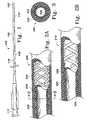
- Figure 4shows a highly desirable termination section (220).
- the termination segment (222)overlaps the next more proximal portion (224) in a half-lap arrangement.
- the lubricious inner liner (206)terminates interior to the half-lap joint.
- a small chamfer (226)-may be placed at the distal extremity so to allow a better passage of the device through blood vessels. Obviously chamfer (226) may be in other suitable shapes.
- the terminal portion (222)may be heat welded onto the remainder of the catheter assembly.
- Figures 5 and 6show desired shapes for the terminal regions of the inventive catheter.
- a catheterwhich has been molded so that it has a radiused 45° turn near to its distal end.
- Figure 6shows a pair of radiused turns to produce a catheter having a specific end configuration. It is within the scope of this invention that any variation of distal tip be accommodated to this structure. Because of the slightly harder terminal tip, the more proximal portions are used to progress the catheter further into the vasculature. Consequently, these tips are of more use in this inventive catheter than are others known in the art.
- Figure 7shows a further variation of the invention in which the catheter device shown in any of the preceding Figures is covered with an outer tubing (250) which "necks down" distally of the terminal section (222) and fits tightly about micro-catheter (252).
- the outer covering (250)may be made of , e.g., a shrink-wrap material such as irradiated and oriented polyethylene, which has been shrunk onto the shaft of the catheter assembly.
- the variation shown in Figure 7has one or more slits (254) which operate as "one-way” valves against the micro-catheter (252) outer surface. This valving region prevents the body fluids from flowing into the catheter yet allows fluids such as radio-opaque materials to flow outwardly.
- the outer covering (250)may extend proximally up the catheter as long as is convenient.
- FIG 8shows still another variation (260) of the inventive guide catheter assembly.
- the micro-catheter (252)is shown extending from the distal end of the guide catheter (260).
- the terminal section (262) in this variationis quite extensive.
- the terminal section (262)has a narrow diameter section (264) and a papered section (268).
- the inner lumen of narrow diameter section (266)fits closely about the outer diameter of microcatheter (252), e.g., with a clearance of 0.002" (50.8 ⁇ m) or so.
- Radio-opaque materialsmay be ejected through the end of the catheter assembly in the annular space outside the micro-catheter (252).
- radio-opaque fluidsmay also be ejected through the hole to improve visibility of the vessel.
- the braid reinforced sectionsare only to be found proximal of the terminal section, e.g., beginning in the section (264).
Landscapes
- Health & Medical Sciences (AREA)
- Life Sciences & Earth Sciences (AREA)
- Biophysics (AREA)
- Pulmonology (AREA)
- Engineering & Computer Science (AREA)
- Anesthesiology (AREA)
- Biomedical Technology (AREA)
- Heart & Thoracic Surgery (AREA)
- Hematology (AREA)
- Animal Behavior & Ethology (AREA)
- General Health & Medical Sciences (AREA)
- Public Health (AREA)
- Veterinary Medicine (AREA)
- Media Introduction/Drainage Providing Device (AREA)
Description
Figure 3 in Krasnicki et al., describes another variation of the endoscopic device in which adifferent selection of polymer tubing is utilized but the placement of the filamentarysupport remains varied in an intermediate material of an elastomer. In some variations ofthe device, the filament is strongly bonded to the inner tubular substrate using an adhesive37 "such as an epoxy cement having sufficient bond strength to held the filament to thesubstrate as it is deformed into a tight radius." See, column 3, lines 50 and following.
| Section | length (cm) | preferred | Shore Hardness | |
| 102 | 0.2-0.6 | PEBAX | 33D- | |
| 104 | 5-9 | PEBAX | 30D- | |
| 106 | 3-7 | PEBAX | 48D- | |
| 108 | 1-9 | PEBAX | 60D- | |
| 110 | 50-70 | NYLON 11/ | 72D-85D | |
| NYLON 12 |
Claims (9)
- An intravascular guiding catheter comprising:wherein the hardness of the polymeric material of said terminal shaftmember (102) is harder than the polymeric material forming the outer layer of saiddistal shaft member (104).an elongate, tubular shaft formed from at least two tubular shaft member (102, 104, 106, 108, 110),said elongate, tubular shaft including:a.) a distal shaft member (104) formed of an outer polymeric materialhaving a braided reinforcing layer embedded therein and lined with an inner lubriciouspolymeric material, andb.) a terminal shaft member (102) formed of a polymeric material, free ofbraided reinforcing, having a wall and a lumen therethrough, and secured to said distalshaft member and located distally of said distal shaft member,
- The catheter of claim wherein the elongate shaft further comprises aprimary midshaft tubular member (106) proximally adjacent said distal shaft member (104) and havingan outer covering comprising a material harder than the material forming the outercovering layer of said distal shaft member (104).
- The catheter of claim 2 wherein the elongate shaft further comprises asecondary midshaft member (108) proximally adjacent said primary midshaft member andhaving an outer polymeric layer with a hardness greater than the outer covering layer ofsaid primary midshaft member (106).
- The catheter of claim 3 wherein the elongate shaft further comprises aproximal shaft member (110) proximally adjacent said secondary midshaft member and havingan outer covering harder than the outer covering of the secondary midshaft member (108).
- The catheter of claim 4 wherein the braid extends continuously from theproximal shaft member (110) to the distal end of the distal shaft member (104).
- The catheter of claim 4 wherein each of the distal shaft member (104), primarymidshaft tubular member (106), secondary midshaft tubular member (108), and the proximal shaftmember (110) contains a braid which is not continuous between such members.
- The catheter of any preceding claim wherein the braid comprises a stainless steel.
- The catheter of any preceding claim wherein the braid comprises a superelastic alloy.
- The catheter of any preceding claim wherein the terminal shaft member and the distalshaft member each have diameters and the diameter of the terminal shaft member issmaller than the diameter of the distal shaft member.
Applications Claiming Priority (3)
| Application Number | Priority Date | Filing Date | Title |
|---|---|---|---|
| US729237 | 1996-10-09 | ||
| US08/729,237US5971975A (en) | 1996-10-09 | 1996-10-09 | Guide catheter with enhanced guidewire tracking |
| PCT/US1997/015850WO1998015311A1 (en) | 1996-10-09 | 1997-10-07 | Guide catheter with enhanced guidewire tracking |
Publications (2)
| Publication Number | Publication Date |
|---|---|
| EP0930910A1 EP0930910A1 (en) | 1999-07-28 |
| EP0930910B1true EP0930910B1 (en) | 2004-01-14 |
Family
ID=24930144
Family Applications (1)
| Application Number | Title | Priority Date | Filing Date |
|---|---|---|---|
| EP97910708AExpired - LifetimeEP0930910B1 (en) | 1996-10-09 | 1997-10-07 | Guide catheter with enhanced guidewire tracking |
Country Status (6)
| Country | Link |
|---|---|
| US (1) | US5971975A (en) |
| EP (1) | EP0930910B1 (en) |
| JP (1) | JP2001501846A (en) |
| AU (1) | AU4800997A (en) |
| DE (1) | DE69727238T2 (en) |
| WO (1) | WO1998015311A1 (en) |
Families Citing this family (236)
| Publication number | Priority date | Publication date | Assignee | Title |
|---|---|---|---|---|
| US20030069522A1 (en) | 1995-12-07 | 2003-04-10 | Jacobsen Stephen J. | Slotted medical device |
| US6251092B1 (en)* | 1997-12-30 | 2001-06-26 | Medtronic, Inc. | Deflectable guiding catheter |
| US6203505B1 (en)* | 1998-06-05 | 2001-03-20 | Advanced Cardiovascular Systems, Inc. | Guidewires having a vapor deposited primer coat |
| US6245053B1 (en)* | 1998-11-09 | 2001-06-12 | Medtronic, Inc. | Soft tip guiding catheter and method of fabrication |
| US6591472B1 (en)* | 1998-12-08 | 2003-07-15 | Medtronic, Inc. | Multiple segment catheter and method of fabrication |
| US6355027B1 (en)* | 1999-06-09 | 2002-03-12 | Possis Medical, Inc. | Flexible microcatheter |
| US6398791B1 (en)* | 1999-06-11 | 2002-06-04 | Scimed Life Systems Inc | Variable composite sheath with interrupted sections |
| CA2378720A1 (en)* | 1999-07-23 | 2001-02-01 | Tfx Medical Extrusion Products | Catheter device having multi-lumen reinforced shaft and method of manufacture for same |
| US6648874B2 (en)* | 2000-02-28 | 2003-11-18 | Scimed Life Systems, Inc. | Guide catheter with lubricious inner liner |
| US6500130B2 (en) | 2000-12-21 | 2002-12-31 | Scimed Life Systems, Inc. | Steerable guidewire |
| DE10105592A1 (en) | 2001-02-06 | 2002-08-08 | Achim Goepferich | Placeholder for drug release in the frontal sinus |
| US20020183781A1 (en)* | 2001-04-17 | 2002-12-05 | Brendan Casey | Catheter |
| US20090163946A1 (en)* | 2001-04-17 | 2009-06-25 | Salviac Limited | Catheter |
| US6716207B2 (en) | 2001-05-22 | 2004-04-06 | Scimed Life Systems, Inc. | Torqueable and deflectable medical device shaft |
| DE20110121U1 (en)* | 2001-06-19 | 2002-12-05 | B. Braun Melsungen Ag, 34212 Melsungen | catheter |
| US6776945B2 (en)* | 2001-07-03 | 2004-08-17 | Scimed Life Systems, Inc. | Medical device with extruded member having helical orientation |
| US20030009208A1 (en) | 2001-07-05 | 2003-01-09 | Precision Vascular Systems, Inc. | Torqueable soft tip medical device and method of usage |
| JP2003250901A (en)* | 2002-02-28 | 2003-09-09 | Toray Ind Inc | Medical tube having excellent x-ray contrasting property |
| GB0205772D0 (en)* | 2002-03-12 | 2002-04-24 | Gill Steven S | Catheter |
| US20030199852A1 (en)* | 2002-04-23 | 2003-10-23 | Endobionics, Inc. | Attachment joints with polymer encapsulation |
| US7115134B2 (en) | 2002-07-22 | 2006-10-03 | Chambers Technology, Llc. | Catheter with flexible tip and shape retention |
| DE60334122D1 (en) | 2002-07-25 | 2010-10-21 | Boston Scient Ltd | MEDICAL DEVICE FOR NAVIGATING THROUGH ANATOMY |
| US7914467B2 (en) | 2002-07-25 | 2011-03-29 | Boston Scientific Scimed, Inc. | Tubular member having tapered transition for use in a medical device |
| US7004937B2 (en)* | 2002-07-31 | 2006-02-28 | Cryocor, Inc. | Wire reinforced articulation segment |
| US7309318B2 (en)* | 2002-09-18 | 2007-12-18 | Boston Scientific Scimed, Inc. | Flexible composite guidewire for intravascular catheter |
| US8317816B2 (en) | 2002-09-30 | 2012-11-27 | Acclarent, Inc. | Balloon catheters and methods for treating paranasal sinuses |
| US20110172644A1 (en)* | 2002-12-04 | 2011-07-14 | Zanoni Michael S | Multi layer coextruded catheter shaft |
| DE50209306D1 (en)* | 2002-12-31 | 2007-03-08 | Abbott Lab Vascular Entpr Ltd | Catheter with a more flexible area between stem and tip, and method of making the same |
| US8377035B2 (en) | 2003-01-17 | 2013-02-19 | Boston Scientific Scimed, Inc. | Unbalanced reinforcement members for medical device |
| US7169118B2 (en) | 2003-02-26 | 2007-01-30 | Scimed Life Systems, Inc. | Elongate medical device with distal cap |
| ES2325398T3 (en) | 2003-02-26 | 2009-09-03 | Boston Scientific Limited | BALL CATETER. |
| US8256428B2 (en)* | 2003-03-12 | 2012-09-04 | Biosense Webster, Inc. | Method for treating tissue |
| US7276062B2 (en)* | 2003-03-12 | 2007-10-02 | Biosence Webster, Inc. | Deflectable catheter with hinge |
| US7001369B2 (en) | 2003-03-27 | 2006-02-21 | Scimed Life Systems, Inc. | Medical device |
| AU2004229523B2 (en) | 2003-04-14 | 2008-09-25 | Cook Medical Technologies Llc | Large diameter delivery catheter/sheath |
| DK1631343T3 (en) | 2003-04-28 | 2008-01-28 | Cook Inc | Flexible insertion casing with varying durometer value |
| DE202004021953U1 (en) | 2003-09-12 | 2013-06-19 | Vessix Vascular, Inc. | Selectable eccentric remodeling and / or ablation of atherosclerotic material |
| US7771369B2 (en)* | 2003-12-05 | 2010-08-10 | Boston Scientific Scimed, Inc. | Guide catheter with removable support |
| US7824345B2 (en) | 2003-12-22 | 2010-11-02 | Boston Scientific Scimed, Inc. | Medical device with push force limiter |
| US7747314B2 (en)* | 2003-12-30 | 2010-06-29 | Boston Scientific Scimed, Inc. | Distal assembly for a medical device |
| US8864787B2 (en) | 2004-04-21 | 2014-10-21 | Acclarent, Inc. | Ethmoidotomy system and implantable spacer devices having therapeutic substance delivery capability for treatment of paranasal sinusitis |
| US7462175B2 (en) | 2004-04-21 | 2008-12-09 | Acclarent, Inc. | Devices, systems and methods for treating disorders of the ear, nose and throat |
| US7419497B2 (en) | 2004-04-21 | 2008-09-02 | Acclarent, Inc. | Methods for treating ethmoid disease |
| US9351750B2 (en) | 2004-04-21 | 2016-05-31 | Acclarent, Inc. | Devices and methods for treating maxillary sinus disease |
| US20060063973A1 (en) | 2004-04-21 | 2006-03-23 | Acclarent, Inc. | Methods and apparatus for treating disorders of the ear, nose and throat |
| US7803150B2 (en) | 2004-04-21 | 2010-09-28 | Acclarent, Inc. | Devices, systems and methods useable for treating sinusitis |
| US20060004323A1 (en) | 2004-04-21 | 2006-01-05 | Exploramed Nc1, Inc. | Apparatus and methods for dilating and modifying ostia of paranasal sinuses and other intranasal or paranasal structures |
| US20070208252A1 (en) | 2004-04-21 | 2007-09-06 | Acclarent, Inc. | Systems and methods for performing image guided procedures within the ear, nose, throat and paranasal sinuses |
| US9399121B2 (en) | 2004-04-21 | 2016-07-26 | Acclarent, Inc. | Systems and methods for transnasal dilation of passageways in the ear, nose or throat |
| US20190314620A1 (en) | 2004-04-21 | 2019-10-17 | Acclarent, Inc. | Apparatus and methods for dilating and modifying ostia of paranasal sinuses and other intranasal or paranasal structures |
| US10188413B1 (en) | 2004-04-21 | 2019-01-29 | Acclarent, Inc. | Deflectable guide catheters and related methods |
| US7559925B2 (en) | 2006-09-15 | 2009-07-14 | Acclarent Inc. | Methods and devices for facilitating visualization in a surgical environment |
| US7361168B2 (en) | 2004-04-21 | 2008-04-22 | Acclarent, Inc. | Implantable device and methods for delivering drugs and other substances to treat sinusitis and other disorders |
| US9101384B2 (en) | 2004-04-21 | 2015-08-11 | Acclarent, Inc. | Devices, systems and methods for diagnosing and treating sinusitis and other disorders of the ears, Nose and/or throat |
| US8932276B1 (en) | 2004-04-21 | 2015-01-13 | Acclarent, Inc. | Shapeable guide catheters and related methods |
| US8702626B1 (en) | 2004-04-21 | 2014-04-22 | Acclarent, Inc. | Guidewires for performing image guided procedures |
| US8764729B2 (en) | 2004-04-21 | 2014-07-01 | Acclarent, Inc. | Frontal sinus spacer |
| US8747389B2 (en) | 2004-04-21 | 2014-06-10 | Acclarent, Inc. | Systems for treating disorders of the ear, nose and throat |
| US8894614B2 (en) | 2004-04-21 | 2014-11-25 | Acclarent, Inc. | Devices, systems and methods useable for treating frontal sinusitis |
| US9554691B2 (en) | 2004-04-21 | 2017-01-31 | Acclarent, Inc. | Endoscopic methods and devices for transnasal procedures |
| US20070167682A1 (en) | 2004-04-21 | 2007-07-19 | Acclarent, Inc. | Endoscopic methods and devices for transnasal procedures |
| US7654997B2 (en) | 2004-04-21 | 2010-02-02 | Acclarent, Inc. | Devices, systems and methods for diagnosing and treating sinusitus and other disorders of the ears, nose and/or throat |
| US9089258B2 (en) | 2004-04-21 | 2015-07-28 | Acclarent, Inc. | Endoscopic methods and devices for transnasal procedures |
| US20060030835A1 (en)* | 2004-06-29 | 2006-02-09 | Sherman Darren R | Catheter shaft tubes and methods of making |
| US7166100B2 (en)* | 2004-06-29 | 2007-01-23 | Cordis Neurovascular, Inc. | Balloon catheter shaft design |
| US7850675B2 (en)* | 2004-07-20 | 2010-12-14 | Boston Scientific Scimed, Inc. | Reinforced venous access catheter |
| US20070276354A1 (en)* | 2004-07-21 | 2007-11-29 | Cook Incorporated | Introducer Sheath and Method for Making |
| US20060144408A1 (en)* | 2004-07-23 | 2006-07-06 | Ferry Steven J | Micro-catheter device and method of using same |
| US9713730B2 (en) | 2004-09-10 | 2017-07-25 | Boston Scientific Scimed, Inc. | Apparatus and method for treatment of in-stent restenosis |
| US8396548B2 (en) | 2008-11-14 | 2013-03-12 | Vessix Vascular, Inc. | Selective drug delivery in a lumen |
| US7682352B2 (en)* | 2004-09-28 | 2010-03-23 | Medtronic Vascular, Inc. | Catheter with curved distal section having reinforcing strip and method of making same |
| US7632242B2 (en) | 2004-12-09 | 2009-12-15 | Boston Scientific Scimed, Inc. | Catheter including a compliant balloon |
| US7815599B2 (en) | 2004-12-10 | 2010-10-19 | Boston Scientific Scimed, Inc. | Catheter having an ultra soft tip and methods for making the same |
| JP2006333966A (en)* | 2005-05-31 | 2006-12-14 | Kaneka Corp | Catheter tube for embolus coil delivery |
| US8951225B2 (en) | 2005-06-10 | 2015-02-10 | Acclarent, Inc. | Catheters with non-removable guide members useable for treatment of sinusitis |
| US20070014945A1 (en)* | 2005-07-12 | 2007-01-18 | Boston Scientific Scimed, Inc. | Guidewire with varied lubricity |
| US9445784B2 (en) | 2005-09-22 | 2016-09-20 | Boston Scientific Scimed, Inc | Intravascular ultrasound catheter |
| US8114113B2 (en) | 2005-09-23 | 2012-02-14 | Acclarent, Inc. | Multi-conduit balloon catheter |
| US7850623B2 (en) | 2005-10-27 | 2010-12-14 | Boston Scientific Scimed, Inc. | Elongate medical device with continuous reinforcement member |
| US20070225680A1 (en)* | 2006-03-21 | 2007-09-27 | Medtronic Vascular, Inc. | Guiding catheter with chemically softened distal portion and method of making same |
| US8019435B2 (en) | 2006-05-02 | 2011-09-13 | Boston Scientific Scimed, Inc. | Control of arterial smooth muscle tone |
| US8190389B2 (en) | 2006-05-17 | 2012-05-29 | Acclarent, Inc. | Adapter for attaching electromagnetic image guidance components to a medical device |
| US8551020B2 (en) | 2006-09-13 | 2013-10-08 | Boston Scientific Scimed, Inc. | Crossing guidewire |
| US9820688B2 (en) | 2006-09-15 | 2017-11-21 | Acclarent, Inc. | Sinus illumination lightwire device |
| JP5559539B2 (en) | 2006-10-18 | 2014-07-23 | べシックス・バスキュラー・インコーポレイテッド | System that induces desirable temperature effects on body tissue |
| EP2076198A4 (en) | 2006-10-18 | 2009-12-09 | Minnow Medical Inc | Inducing desirable temperature effects on body tissue |
| EP2455036B1 (en) | 2006-10-18 | 2015-07-15 | Vessix Vascular, Inc. | Tuned RF energy and electrical tissue characterization for selective treatment of target tissues |
| EP2094343B1 (en) | 2006-11-30 | 2017-10-04 | Ingenion Medical Limited | System for implanting a catheter |
| US8556914B2 (en) | 2006-12-15 | 2013-10-15 | Boston Scientific Scimed, Inc. | Medical device including structure for crossing an occlusion in a vessel |
| US8439687B1 (en) | 2006-12-29 | 2013-05-14 | Acclarent, Inc. | Apparatus and method for simulated insertion and positioning of guidewares and other interventional devices |
| US8398696B2 (en)* | 2007-03-01 | 2013-03-19 | Boston Scientific Scimed, Inc. | Microcatheter introducer sheath |
| US8118757B2 (en) | 2007-04-30 | 2012-02-21 | Acclarent, Inc. | Methods and devices for ostium measurement |
| US8485199B2 (en) | 2007-05-08 | 2013-07-16 | Acclarent, Inc. | Methods and devices for protecting nasal turbinate during surgery |
| US7914515B2 (en) | 2007-07-18 | 2011-03-29 | St. Jude Medical, Atrial Fibrillation Division, Inc. | Catheter and introducer catheter having torque transfer layer and method of manufacture |
| US8409114B2 (en) | 2007-08-02 | 2013-04-02 | Boston Scientific Scimed, Inc. | Composite elongate medical device including distal tubular member |
| US8105246B2 (en) | 2007-08-03 | 2012-01-31 | Boston Scientific Scimed, Inc. | Elongate medical device having enhanced torque and methods thereof |
| US8821477B2 (en) | 2007-08-06 | 2014-09-02 | Boston Scientific Scimed, Inc. | Alternative micromachined structures |
| US9808595B2 (en) | 2007-08-07 | 2017-11-07 | Boston Scientific Scimed, Inc | Microfabricated catheter with improved bonding structure |
| US7841994B2 (en) | 2007-11-02 | 2010-11-30 | Boston Scientific Scimed, Inc. | Medical device for crossing an occlusion in a vessel |
| ITMI20072309A1 (en)* | 2007-12-10 | 2009-06-11 | N G C Medical S P A | TUBE PRESENTING AN ENLARGABLE DIAMETER, PARTICULARLY USABLE AS A TUBE FOR VASAL INTRODUCTION DURING HEMODYNAMIC STUDIES AND RELATIVE INTERVENTIONS. |
| US10206821B2 (en) | 2007-12-20 | 2019-02-19 | Acclarent, Inc. | Eustachian tube dilation balloon with ventilation path |
| US8431057B2 (en)* | 2007-12-30 | 2013-04-30 | St. Jude Medical, Atrial Fibrillation Division, Inc. | Catheter shaft and method of its manufacture |
| US8182432B2 (en) | 2008-03-10 | 2012-05-22 | Acclarent, Inc. | Corewire design and construction for medical devices |
| US8376961B2 (en) | 2008-04-07 | 2013-02-19 | Boston Scientific Scimed, Inc. | Micromachined composite guidewire structure with anisotropic bending properties |
| US8096985B2 (en)* | 2008-05-07 | 2012-01-17 | Guided Delivery Systems Inc. | Deflectable guide |
| US9011412B2 (en) | 2008-05-16 | 2015-04-21 | Ford Albritton, IV | Apparatus, system and method for manipulating a surgical catheter and working device with a single hand |
| RU2500337C2 (en) | 2008-07-30 | 2013-12-10 | Аккларент, Инк. | Device and methods of identifying orifice of paranasal sinus |
| US8535243B2 (en) | 2008-09-10 | 2013-09-17 | Boston Scientific Scimed, Inc. | Medical devices and tapered tubular members for use in medical devices |
| BRPI0919195A2 (en) | 2008-09-18 | 2019-09-24 | Acclarent Inc | Methods and Apparatus for the Treatment of Ear, Nose, and Throat Disorders |
| EP2355737B1 (en) | 2008-11-17 | 2021-08-11 | Boston Scientific Scimed, Inc. | Selective accumulation of energy without knowledge of tissue topography |
| WO2010068793A1 (en)* | 2008-12-10 | 2010-06-17 | Microvention, Inc. | Microcatheter |
| US8795254B2 (en) | 2008-12-10 | 2014-08-05 | Boston Scientific Scimed, Inc. | Medical devices with a slotted tubular member having improved stress distribution |
| WO2010085456A1 (en) | 2009-01-20 | 2010-07-29 | Guided Delivery Systems Inc. | Anchor deployment devices and related methods |
| US20100241155A1 (en) | 2009-03-20 | 2010-09-23 | Acclarent, Inc. | Guide system with suction |
| US8435290B2 (en) | 2009-03-31 | 2013-05-07 | Acclarent, Inc. | System and method for treatment of non-ventilating middle ear by providing a gas pathway through the nasopharynx |
| US7978742B1 (en) | 2010-03-24 | 2011-07-12 | Corning Incorporated | Methods for operating diode lasers |
| US20110060316A1 (en)* | 2009-09-04 | 2011-03-10 | Dicarlo Paul | Tipped Ribbon Integrated Guidewire |
| JP5013380B2 (en)* | 2009-10-29 | 2012-08-29 | 朝日インテック株式会社 | Medical tube and catheter using the same |
| US8137293B2 (en) | 2009-11-17 | 2012-03-20 | Boston Scientific Scimed, Inc. | Guidewires including a porous nickel-titanium alloy |
| US8551021B2 (en) | 2010-03-31 | 2013-10-08 | Boston Scientific Scimed, Inc. | Guidewire with an improved flexural rigidity profile |
| WO2011126580A2 (en) | 2010-04-09 | 2011-10-13 | Minnow Medical, Inc. | Power generating and control apparatus for the treatment of tissue |
| US9192790B2 (en) | 2010-04-14 | 2015-11-24 | Boston Scientific Scimed, Inc. | Focused ultrasonic renal denervation |
| US8473067B2 (en) | 2010-06-11 | 2013-06-25 | Boston Scientific Scimed, Inc. | Renal denervation and stimulation employing wireless vascular energy transfer arrangement |
| US9084609B2 (en) | 2010-07-30 | 2015-07-21 | Boston Scientific Scime, Inc. | Spiral balloon catheter for renal nerve ablation |
| US9358365B2 (en) | 2010-07-30 | 2016-06-07 | Boston Scientific Scimed, Inc. | Precision electrode movement control for renal nerve ablation |
| US9155589B2 (en) | 2010-07-30 | 2015-10-13 | Boston Scientific Scimed, Inc. | Sequential activation RF electrode set for renal nerve ablation |
| US9463062B2 (en) | 2010-07-30 | 2016-10-11 | Boston Scientific Scimed, Inc. | Cooled conductive balloon RF catheter for renal nerve ablation |
| US9408661B2 (en) | 2010-07-30 | 2016-08-09 | Patrick A. Haverkost | RF electrodes on multiple flexible wires for renal nerve ablation |
| US9155492B2 (en) | 2010-09-24 | 2015-10-13 | Acclarent, Inc. | Sinus illumination lightwire device |
| US9084610B2 (en) | 2010-10-21 | 2015-07-21 | Medtronic Ardian Luxembourg S.A.R.L. | Catheter apparatuses, systems, and methods for renal neuromodulation |
| US8974451B2 (en) | 2010-10-25 | 2015-03-10 | Boston Scientific Scimed, Inc. | Renal nerve ablation using conductive fluid jet and RF energy |
| US9220558B2 (en) | 2010-10-27 | 2015-12-29 | Boston Scientific Scimed, Inc. | RF renal denervation catheter with multiple independent electrodes |
| US9028485B2 (en) | 2010-11-15 | 2015-05-12 | Boston Scientific Scimed, Inc. | Self-expanding cooling electrode for renal nerve ablation |
| US9089350B2 (en) | 2010-11-16 | 2015-07-28 | Boston Scientific Scimed, Inc. | Renal denervation catheter with RF electrode and integral contrast dye injection arrangement |
| US9668811B2 (en) | 2010-11-16 | 2017-06-06 | Boston Scientific Scimed, Inc. | Minimally invasive access for renal nerve ablation |
| US9326751B2 (en) | 2010-11-17 | 2016-05-03 | Boston Scientific Scimed, Inc. | Catheter guidance of external energy for renal denervation |
| US9060761B2 (en) | 2010-11-18 | 2015-06-23 | Boston Scientific Scime, Inc. | Catheter-focused magnetic field induced renal nerve ablation |
| US9023034B2 (en) | 2010-11-22 | 2015-05-05 | Boston Scientific Scimed, Inc. | Renal ablation electrode with force-activatable conduction apparatus |
| US9192435B2 (en) | 2010-11-22 | 2015-11-24 | Boston Scientific Scimed, Inc. | Renal denervation catheter with cooled RF electrode |
| US20120157993A1 (en) | 2010-12-15 | 2012-06-21 | Jenson Mark L | Bipolar Off-Wall Electrode Device for Renal Nerve Ablation |
| US9220561B2 (en) | 2011-01-19 | 2015-12-29 | Boston Scientific Scimed, Inc. | Guide-compatible large-electrode catheter for renal nerve ablation with reduced arterial injury |
| US8795202B2 (en) | 2011-02-04 | 2014-08-05 | Boston Scientific Scimed, Inc. | Guidewires and methods for making and using the same |
| JP5110716B2 (en)* | 2011-02-25 | 2012-12-26 | 朝日インテック株式会社 | catheter |
| US9072874B2 (en) | 2011-05-13 | 2015-07-07 | Boston Scientific Scimed, Inc. | Medical devices with a heat transfer region and a heat sink region and methods for manufacturing medical devices |
| CN103813745B (en) | 2011-07-20 | 2016-06-29 | 波士顿科学西美德公司 | In order to visualize, be directed at and to melt transcutaneous device and the method for nerve |
| EP2734264B1 (en) | 2011-07-22 | 2018-11-21 | Boston Scientific Scimed, Inc. | Nerve modulation system with a nerve modulation element positionable in a helical guide |
| WO2013055826A1 (en) | 2011-10-10 | 2013-04-18 | Boston Scientific Scimed, Inc. | Medical devices including ablation electrodes |
| US9420955B2 (en) | 2011-10-11 | 2016-08-23 | Boston Scientific Scimed, Inc. | Intravascular temperature monitoring system and method |
| EP2765940B1 (en) | 2011-10-11 | 2015-08-26 | Boston Scientific Scimed, Inc. | Off-wall electrode device for nerve modulation |
| US9364284B2 (en) | 2011-10-12 | 2016-06-14 | Boston Scientific Scimed, Inc. | Method of making an off-wall spacer cage |
| US9162046B2 (en) | 2011-10-18 | 2015-10-20 | Boston Scientific Scimed, Inc. | Deflectable medical devices |
| EP2768568B1 (en) | 2011-10-18 | 2020-05-06 | Boston Scientific Scimed, Inc. | Integrated crossing balloon catheter |
| US8951251B2 (en) | 2011-11-08 | 2015-02-10 | Boston Scientific Scimed, Inc. | Ostial renal nerve ablation |
| WO2013074813A1 (en) | 2011-11-15 | 2013-05-23 | Boston Scientific Scimed, Inc. | Device and methods for renal nerve modulation monitoring |
| US9119632B2 (en) | 2011-11-21 | 2015-09-01 | Boston Scientific Scimed, Inc. | Deflectable renal nerve ablation catheter |
| US9265969B2 (en) | 2011-12-21 | 2016-02-23 | Cardiac Pacemakers, Inc. | Methods for modulating cell function |
| US9028472B2 (en) | 2011-12-23 | 2015-05-12 | Vessix Vascular, Inc. | Methods and apparatuses for remodeling tissue of or adjacent to a body passage |
| EP2797534A1 (en) | 2011-12-28 | 2014-11-05 | Boston Scientific Scimed, Inc. | Device and methods for nerve modulation using a novel ablation catheter with polymeric ablative elements |
| US9050106B2 (en) | 2011-12-29 | 2015-06-09 | Boston Scientific Scimed, Inc. | Off-wall electrode device and methods for nerve modulation |
| US9072624B2 (en) | 2012-02-23 | 2015-07-07 | Covidien Lp | Luminal stenting |
| CN102553046A (en)* | 2012-02-23 | 2012-07-11 | 苏州伟康医疗器械有限公司 | Disposable oral-nasal oxygen tube |
| US9981113B2 (en)* | 2012-03-14 | 2018-05-29 | Access Scientific, Llc | Flexible medical article and method of making the same |
| EP2825363B1 (en) | 2012-03-14 | 2020-04-29 | Asspv, Llc | Flexible medical article |
| US9717554B2 (en) | 2012-03-26 | 2017-08-01 | Biosense Webster (Israel) Ltd. | Catheter with composite construction |
| US10660703B2 (en) | 2012-05-08 | 2020-05-26 | Boston Scientific Scimed, Inc. | Renal nerve modulation devices |
| US10639099B2 (en) | 2012-05-25 | 2020-05-05 | Biosense Webster (Israel), Ltd. | Catheter having a distal section with spring sections for biased deflection |
| US10321946B2 (en) | 2012-08-24 | 2019-06-18 | Boston Scientific Scimed, Inc. | Renal nerve modulation devices with weeping RF ablation balloons |
| CN104780859B (en) | 2012-09-17 | 2017-07-25 | 波士顿科学西美德公司 | Self-positioning electrode systems and methods for renal neuromodulation |
| US10549127B2 (en) | 2012-09-21 | 2020-02-04 | Boston Scientific Scimed, Inc. | Self-cooling ultrasound ablation catheter |
| US10398464B2 (en) | 2012-09-21 | 2019-09-03 | Boston Scientific Scimed, Inc. | System for nerve modulation and innocuous thermal gradient nerve block |
| CN104869930B (en) | 2012-10-10 | 2020-12-25 | 波士顿科学国际有限公司 | Renal neuromodulation apparatus and methods |
| US9044575B2 (en) | 2012-10-22 | 2015-06-02 | Medtronic Adrian Luxembourg S.a.r.l. | Catheters with enhanced flexibility and associated devices, systems, and methods |
| WO2014143571A1 (en) | 2013-03-11 | 2014-09-18 | Boston Scientific Scimed, Inc. | Medical devices for modulating nerves |
| WO2014163987A1 (en) | 2013-03-11 | 2014-10-09 | Boston Scientific Scimed, Inc. | Medical devices for modulating nerves |
| US9808311B2 (en) | 2013-03-13 | 2017-11-07 | Boston Scientific Scimed, Inc. | Deflectable medical devices |
| EP2967734B1 (en) | 2013-03-15 | 2019-05-15 | Boston Scientific Scimed, Inc. | Methods and apparatuses for remodeling tissue of or adjacent to a body passage |
| CN105228546B (en) | 2013-03-15 | 2017-11-14 | 波士顿科学国际有限公司 | Medical devices and methods for treating hypertension utilizing impedance compensation |
| US10265122B2 (en) | 2013-03-15 | 2019-04-23 | Boston Scientific Scimed, Inc. | Nerve ablation devices and related methods of use |
| US9629684B2 (en) | 2013-03-15 | 2017-04-25 | Acclarent, Inc. | Apparatus and method for treatment of ethmoid sinusitis |
| US9433437B2 (en) | 2013-03-15 | 2016-09-06 | Acclarent, Inc. | Apparatus and method for treatment of ethmoid sinusitis |
| EP2996754B1 (en) | 2013-05-18 | 2023-04-26 | Medtronic Ardian Luxembourg S.à.r.l. | Neuromodulation catheters with shafts for enhanced flexibility and control and associated devices and systems |
| CN105473091B (en) | 2013-06-21 | 2020-01-21 | 波士顿科学国际有限公司 | Renal denervation balloon catheter with co-movable electrode supports |
| CN105473092B (en) | 2013-06-21 | 2019-05-17 | 波士顿科学国际有限公司 | The medical instrument for renal nerve ablation with rotatable shaft |
| US9707036B2 (en) | 2013-06-25 | 2017-07-18 | Boston Scientific Scimed, Inc. | Devices and methods for nerve modulation using localized indifferent electrodes |
| CN105358084B (en) | 2013-07-01 | 2018-11-09 | 波士顿科学国际有限公司 | Medical instrument for renal nerve ablation |
| US10413357B2 (en) | 2013-07-11 | 2019-09-17 | Boston Scientific Scimed, Inc. | Medical device with stretchable electrode assemblies |
| CN105377169B (en) | 2013-07-11 | 2019-04-19 | 波士顿科学国际有限公司 | Devices and methods for neuromodulation |
| US9925001B2 (en) | 2013-07-19 | 2018-03-27 | Boston Scientific Scimed, Inc. | Spiral bipolar electrode renal denervation balloon |
| US10342609B2 (en) | 2013-07-22 | 2019-07-09 | Boston Scientific Scimed, Inc. | Medical devices for renal nerve ablation |
| US10695124B2 (en) | 2013-07-22 | 2020-06-30 | Boston Scientific Scimed, Inc. | Renal nerve ablation catheter having twist balloon |
| CN105473093B (en) | 2013-08-22 | 2019-02-05 | 波士顿科学国际有限公司 | Flexible circuit with improved adhesion to renal neuromodulation balloon |
| US9782186B2 (en) | 2013-08-27 | 2017-10-10 | Covidien Lp | Vascular intervention system |
| US10045867B2 (en) | 2013-08-27 | 2018-08-14 | Covidien Lp | Delivery of medical devices |
| US9895194B2 (en) | 2013-09-04 | 2018-02-20 | Boston Scientific Scimed, Inc. | Radio frequency (RF) balloon catheter having flushing and cooling capability |
| EP3043733A1 (en) | 2013-09-13 | 2016-07-20 | Boston Scientific Scimed, Inc. | Ablation balloon with vapor deposited cover layer |
| WO2015048795A2 (en)* | 2013-09-30 | 2015-04-02 | Biocardia, Inc. | Radial and trans-endocardial delivery catheter |
| EP3057488B1 (en) | 2013-10-14 | 2018-05-16 | Boston Scientific Scimed, Inc. | High resolution cardiac mapping electrode array catheter |
| US11246654B2 (en) | 2013-10-14 | 2022-02-15 | Boston Scientific Scimed, Inc. | Flexible renal nerve ablation devices and related methods of use and manufacture |
| US9962223B2 (en) | 2013-10-15 | 2018-05-08 | Boston Scientific Scimed, Inc. | Medical device balloon |
| US9770606B2 (en) | 2013-10-15 | 2017-09-26 | Boston Scientific Scimed, Inc. | Ultrasound ablation catheter with cooling infusion and centering basket |
| EP3057521B1 (en) | 2013-10-18 | 2020-03-25 | Boston Scientific Scimed, Inc. | Balloon catheters with flexible conducting wires |
| CN105658163B (en) | 2013-10-25 | 2020-08-18 | 波士顿科学国际有限公司 | Embedded thermocouple in denervation flexible circuit |
| EP3082934A4 (en)* | 2013-12-19 | 2017-08-09 | Smiths Medical ASD, Inc. | Soft tip catheter |
| EP3091922B1 (en) | 2014-01-06 | 2018-10-17 | Boston Scientific Scimed, Inc. | Tear resistant flex circuit assembly |
| EP4253024B1 (en) | 2014-01-27 | 2025-02-26 | Medtronic Ireland Manufacturing Unlimited Company | Neuromodulation catheters having jacketed neuromodulation elements and related devices |
| US11000679B2 (en) | 2014-02-04 | 2021-05-11 | Boston Scientific Scimed, Inc. | Balloon protection and rewrapping devices and related methods of use |
| CN106572881B (en) | 2014-02-04 | 2019-07-26 | 波士顿科学国际有限公司 | Alternative placement of thermal sensors on bipolar electrodes |
| US9901706B2 (en) | 2014-04-11 | 2018-02-27 | Boston Scientific Scimed, Inc. | Catheters and catheter shafts |
| CN106232043B (en) | 2014-04-24 | 2019-07-23 | 美敦力阿迪安卢森堡有限公司 | Nerve modulation conduit and relevant system and method with braiding axle |
| US9636477B2 (en) | 2014-10-09 | 2017-05-02 | Vascular Solutions, Inc. | Catheter |
| US10058321B2 (en) | 2015-03-05 | 2018-08-28 | Ancora Heart, Inc. | Devices and methods of visualizing and determining depth of penetration in cardiac tissue |
| US10357631B2 (en) | 2015-05-29 | 2019-07-23 | Covidien Lp | Catheter with tapering outer diameter |
| US11219740B2 (en) | 2015-05-29 | 2022-01-11 | Covidien Lp | Catheter including tapering coil member |
| JP6426068B2 (en)* | 2015-08-10 | 2018-11-21 | 朝日インテック株式会社 | Catheter and balloon catheter |
| US11351048B2 (en) | 2015-11-16 | 2022-06-07 | Boston Scientific Scimed, Inc. | Stent delivery systems with a reinforced deployment sheath |
| US10582914B2 (en) | 2016-01-15 | 2020-03-10 | Covidien Lp | Navigable endobronchial tool to access tissue outside a bronchus |
| US10653873B2 (en) | 2016-05-26 | 2020-05-19 | Merit Medical Systems, Inc. | Expandable introducer assembly |
| US10376396B2 (en) | 2017-01-19 | 2019-08-13 | Covidien Lp | Coupling units for medical device delivery systems |
| US10926060B2 (en) | 2017-03-02 | 2021-02-23 | Covidien Lp | Flexible tip catheter |
| US10537710B2 (en) | 2017-04-20 | 2020-01-21 | Covidien Lp | Catheter including an inner liner with a flexible distal section |
| US10238834B2 (en)* | 2017-08-25 | 2019-03-26 | Teleflex Innovations S.À.R.L. | Catheter |
| US11123209B2 (en) | 2018-04-12 | 2021-09-21 | Covidien Lp | Medical device delivery |
| US11413176B2 (en) | 2018-04-12 | 2022-08-16 | Covidien Lp | Medical device delivery |
| US11071637B2 (en) | 2018-04-12 | 2021-07-27 | Covidien Lp | Medical device delivery |
| US10786377B2 (en) | 2018-04-12 | 2020-09-29 | Covidien Lp | Medical device delivery |
| US10953195B2 (en) | 2018-06-01 | 2021-03-23 | Covidien Lp | Flexible tip catheter |
| WO2020124551A1 (en)* | 2018-12-19 | 2020-06-25 | 深圳市业聚实业有限公司 | Novel microcatheter |
| US11413174B2 (en) | 2019-06-26 | 2022-08-16 | Covidien Lp | Core assembly for medical device delivery systems |
| US11471650B2 (en) | 2019-09-20 | 2022-10-18 | Biosense Webster (Israel) Ltd. | Mechanism for manipulating a puller wire |
| EP3982850B1 (en)* | 2019-10-30 | 2024-04-17 | Boston Scientific Scimed, Inc. | Endoscopic catheter device |
| US11992625B2 (en)* | 2020-07-07 | 2024-05-28 | Covidien Lp | Catheter including variable density structural support member |
| US12168102B2 (en) | 2020-07-07 | 2024-12-17 | Covidien Lp | Catheter including surface-treated structural support member |
| US20220184366A1 (en)* | 2020-12-11 | 2022-06-16 | Interventional Technological LLC | Vascular access sheath and catheter system |
| US12042413B2 (en) | 2021-04-07 | 2024-07-23 | Covidien Lp | Delivery of medical devices |
| US12109137B2 (en) | 2021-07-30 | 2024-10-08 | Covidien Lp | Medical device delivery |
| US11944558B2 (en) | 2021-08-05 | 2024-04-02 | Covidien Lp | Medical device delivery devices, systems, and methods |
Family Cites Families (47)
| Publication number | Priority date | Publication date | Assignee | Title |
|---|---|---|---|---|
| US243396A (en)* | 1881-06-28 | Edwaed peaeee | ||
| US2211975A (en)* | 1937-03-16 | 1940-08-20 | Floyd C Hendrickson | Catheter |
| US2437542A (en)* | 1944-05-05 | 1948-03-09 | American Catheter Corp | Catheter-type instrument |
| US3174851A (en)* | 1961-12-01 | 1965-03-23 | William J Buehler | Nickel-base alloys |
| US3416531A (en)* | 1964-01-02 | 1968-12-17 | Edwards Miles Lowell | Catheter |
| US3351463A (en)* | 1965-08-20 | 1967-11-07 | Alexander G Rozner | High strength nickel-base alloys |
| US3753700A (en)* | 1970-07-02 | 1973-08-21 | Raychem Corp | Heat recoverable alloy |
| US3757768A (en)* | 1972-04-07 | 1973-09-11 | Medical Evaluation Devices And | Manipulable spring guide-catheter and tube for intravenous feeding |
| US3924632A (en)* | 1972-12-07 | 1975-12-09 | William A Cook | Fiber glass reinforced catheter |
| US4657024A (en)* | 1980-02-04 | 1987-04-14 | Teleflex Incorporated | Medical-surgical catheter |
| US4430083A (en)* | 1981-03-06 | 1984-02-07 | American Hospital Supply Corporation | Infusion catheter |
| US4425919A (en)* | 1981-07-27 | 1984-01-17 | Raychem Corporation | Torque transmitting catheter apparatus |
| JPS5886129A (en)* | 1981-11-17 | 1983-05-23 | 旭光学工業株式会社 | Flexible tube of endoscope and production thereof |
| US4516972A (en)* | 1982-01-28 | 1985-05-14 | Advanced Cardiovascular Systems, Inc. | Guiding catheter and method of manufacture |
| US4484586A (en)* | 1982-05-27 | 1984-11-27 | Berkley & Company, Inc. | Hollow conductive medical tubing |
| JPS5936A (en)* | 1982-06-24 | 1984-01-05 | オリンパス光学工業株式会社 | Flexible tube of endoscope |
| US4806182A (en)* | 1985-10-15 | 1989-02-21 | Schneider-Shiley (U.S.A.) Inc. | Method of bonding a hub to a Teflon-lined catheter body |
| JPS62139626A (en)* | 1985-12-13 | 1987-06-23 | オリンパス光学工業株式会社 | Flexible tube for endoscope |
| JPH025799Y2 (en)* | 1986-02-07 | 1990-02-13 | ||
| US4676229A (en)* | 1986-04-09 | 1987-06-30 | Welch Allyn, Inc. | Biopsy channel for an endoscope |
| US4739768B2 (en)* | 1986-06-02 | 1995-10-24 | Target Therapeutics Inc | Catheter for guide-wire tracking |
| FR2608037A1 (en)* | 1986-12-10 | 1988-06-17 | Lenck Lucien | INTUBATION METHOD FOR PERMITTING THE TRANSPLANTATION OF EGG OR EMBRYONIC MATTER, AND MEANS FOR IMPLEMENTING THE SAME |
| FR2613231A1 (en)* | 1987-04-06 | 1988-10-07 | Nivarox Sa | Medical probe intended in particular for performing operations inside the human or animal body |
| US4981478A (en)* | 1988-09-06 | 1991-01-01 | Advanced Cardiovascular Systems | Composite vascular catheter |
| US5037404A (en)* | 1988-11-14 | 1991-08-06 | Cordis Corporation | Catheter having sections of variable torsion characteristics |
| US4985022A (en)* | 1988-11-23 | 1991-01-15 | Med Institute, Inc. | Catheter having durable and flexible segments |
| JPH02283346A (en)* | 1989-04-25 | 1990-11-20 | Olympus Optical Co Ltd | Flexible tube for endoscope |
| JPH07110270B2 (en)* | 1989-06-21 | 1995-11-29 | オリンパス光学工業株式会社 | Endoscope flexible tube skin |
| US5248305A (en)* | 1989-08-04 | 1993-09-28 | Cordis Corporation | Extruded tubing and catheters having helical liquid crystal fibrils |
| EP0421650A1 (en)* | 1989-10-06 | 1991-04-10 | C.R. Bard, Inc. | Multilaminate coiled film catheter construction |
| US5176660A (en)* | 1989-10-23 | 1993-01-05 | Cordis Corporation | Catheter having reinforcing strands |
| US5057092A (en)* | 1990-04-04 | 1991-10-15 | Webster Wilton W Jr | Braided catheter with low modulus warp |
| US5180376A (en)* | 1990-05-01 | 1993-01-19 | Cathco, Inc. | Non-buckling thin-walled sheath for the percutaneous insertion of intraluminal catheters |
| US5217482A (en)* | 1990-08-28 | 1993-06-08 | Scimed Life Systems, Inc. | Balloon catheter with distal guide wire lumen |
| US5178158A (en)* | 1990-10-29 | 1993-01-12 | Boston Scientific Corporation | Convertible guidewire-catheter with soft tip |
| US5222949A (en)* | 1991-07-23 | 1993-06-29 | Intermed, Inc. | Flexible, noncollapsible catheter tube with hard and soft regions |
| JPH05220225A (en)* | 1991-08-26 | 1993-08-31 | Terumo Corp | Catheter |
| JPH0556910A (en)* | 1991-08-29 | 1993-03-09 | Olympus Optical Co Ltd | Tubular inserting means |
| EP0605615A1 (en)* | 1991-09-26 | 1994-07-13 | Medtronic, Inc. | Catheter with spring coil inner lumen |
| AU3666993A (en)* | 1992-02-13 | 1993-09-03 | Navarre Biomedical, Ltd. | Kink resistant tubing apparatus |
| FR2692789B1 (en)* | 1992-06-26 | 1999-09-17 | Vygon | PROBE WITH ADDED TIP. |
| US5531721A (en)* | 1992-07-02 | 1996-07-02 | Scimed Life Systems, Inc. | Multiple member intravascular guide catheter |
| US5313967A (en)* | 1992-07-24 | 1994-05-24 | Medtronic, Inc. | Helical guidewire |
| JP3310031B2 (en)* | 1992-10-23 | 2002-07-29 | テルモ株式会社 | Catheter tube |
| US5405338A (en)* | 1993-08-19 | 1995-04-11 | Cordis Corporation | Helically wound catheters |
| NL9301642A (en)* | 1993-09-22 | 1995-04-18 | Cordis Europ | Microcatheter. |
| WO1995013110A1 (en)* | 1993-11-12 | 1995-05-18 | Micro Interventional Systems | Small diameter, high torque catheter |
- 1996
- 1996-10-09USUS08/729,237patent/US5971975A/ennot_activeExpired - Lifetime
- 1997
- 1997-10-07DEDE69727238Tpatent/DE69727238T2/ennot_activeExpired - Lifetime
- 1997-10-07JPJP10517520Apatent/JP2001501846A/enactivePending
- 1997-10-07AUAU48009/97Apatent/AU4800997A/ennot_activeAbandoned
- 1997-10-07EPEP97910708Apatent/EP0930910B1/ennot_activeExpired - Lifetime
- 1997-10-07WOPCT/US1997/015850patent/WO1998015311A1/enactiveIP Right Grant
Also Published As
| Publication number | Publication date |
|---|---|
| JP2001501846A (en) | 2001-02-13 |
| AU4800997A (en) | 1998-05-05 |
| DE69727238D1 (en) | 2004-02-19 |
| US5971975A (en) | 1999-10-26 |
| DE69727238T2 (en) | 2004-11-25 |
| EP0930910A1 (en) | 1999-07-28 |
| WO1998015311A1 (en) | 1998-04-16 |
Similar Documents
| Publication | Publication Date | Title |
|---|---|---|
| EP0930910B1 (en) | Guide catheter with enhanced guidewire tracking | |
| US6165163A (en) | Soft-tip performance braided catheter | |
| US5951539A (en) | Optimized high performance multiple coil spiral-wound vascular catheter | |
| US6824553B1 (en) | High performance braided catheter | |
| US6053903A (en) | High performance spiral-wound catheter | |
| US5891112A (en) | High performance superelastic alloy braid reinforced catheter | |
| US6143013A (en) | High performance braided catheter | |
| US6152912A (en) | Optimized high performance spiral-wound vascular catheter | |
| US5702373A (en) | Composite super-elastic alloy braid reinforced catheter | |
| EP1019130B1 (en) | Peripheral vascular delivery catheter | |
| US6159187A (en) | Reinforced catheter with a formable distal tip | |
| EP0810003B1 (en) | Kink-resistant braided catheter with distal side holes | |
| EP0717643B1 (en) | Catheter with kink-resistant distal tip | |
| US5599326A (en) | Catheter with multi-layer section | |
| US6090099A (en) | Multi-layer distal catheter section |
Legal Events
| Date | Code | Title | Description |
|---|---|---|---|
| PUAI | Public reference made under article 153(3) epc to a published international application that has entered the european phase | Free format text:ORIGINAL CODE: 0009012 | |
| 17P | Request for examination filed | Effective date:19990416 | |
| AK | Designated contracting states | Kind code of ref document:A1 Designated state(s):DE DK FR GB IE NL | |
| 17Q | First examination report despatched | Effective date:20020923 | |
| GRAP | Despatch of communication of intention to grant a patent | Free format text:ORIGINAL CODE: EPIDOSNIGR1 | |
| GRAS | Grant fee paid | Free format text:ORIGINAL CODE: EPIDOSNIGR3 | |
| GRAA | (expected) grant | Free format text:ORIGINAL CODE: 0009210 | |
| AK | Designated contracting states | Kind code of ref document:B1 Designated state(s):DE DK FR GB IE NL | |
| REG | Reference to a national code | Ref country code:GB Ref legal event code:FG4D | |
| REG | Reference to a national code | Ref country code:IE Ref legal event code:FG4D | |
| REF | Corresponds to: | Ref document number:69727238 Country of ref document:DE Date of ref document:20040219 Kind code of ref document:P | |
| PG25 | Lapsed in a contracting state [announced via postgrant information from national office to epo] | Ref country code:DK Free format text:LAPSE BECAUSE OF FAILURE TO SUBMIT A TRANSLATION OF THE DESCRIPTION OR TO PAY THE FEE WITHIN THE PRESCRIBED TIME-LIMIT Effective date:20040414 | |
| ET | Fr: translation filed | ||
| PLBE | No opposition filed within time limit | Free format text:ORIGINAL CODE: 0009261 | |
| STAA | Information on the status of an ep patent application or granted ep patent | Free format text:STATUS: NO OPPOSITION FILED WITHIN TIME LIMIT | |
| 26N | No opposition filed | Effective date:20041015 | |
| PGFP | Annual fee paid to national office [announced via postgrant information from national office to epo] | Ref country code:NL Payment date:20070920 Year of fee payment:11 | |
| NLV4 | Nl: lapsed or anulled due to non-payment of the annual fee | Effective date:20090501 | |
| PG25 | Lapsed in a contracting state [announced via postgrant information from national office to epo] | Ref country code:NL Free format text:LAPSE BECAUSE OF NON-PAYMENT OF DUE FEES Effective date:20090501 | |
| REG | Reference to a national code | Ref country code:DE Ref legal event code:R082 Ref document number:69727238 Country of ref document:DE Representative=s name:VOSSIUS & PARTNER PATENTANWAELTE RECHTSANWAELT, DE | |
| REG | Reference to a national code | Ref country code:FR Ref legal event code:PLFP Year of fee payment:20 | |
| PGFP | Annual fee paid to national office [announced via postgrant information from national office to epo] | Ref country code:FR Payment date:20160919 Year of fee payment:20 | |
| PGFP | Annual fee paid to national office [announced via postgrant information from national office to epo] | Ref country code:DE Payment date:20161004 Year of fee payment:20 Ref country code:GB Payment date:20161005 Year of fee payment:20 Ref country code:IE Payment date:20161010 Year of fee payment:20 | |
| REG | Reference to a national code | Ref country code:DE Ref legal event code:R071 Ref document number:69727238 Country of ref document:DE | |
| REG | Reference to a national code | Ref country code:GB Ref legal event code:PE20 Expiry date:20171006 | |
| REG | Reference to a national code | Ref country code:IE Ref legal event code:MK9A | |
| PG25 | Lapsed in a contracting state [announced via postgrant information from national office to epo] | Ref country code:GB Free format text:LAPSE BECAUSE OF EXPIRATION OF PROTECTION Effective date:20171006 Ref country code:IE Free format text:LAPSE BECAUSE OF EXPIRATION OF PROTECTION Effective date:20171007 |