EP0930579B1 - Ringscanner - Google Patents
RingscannerDownload PDFInfo
- Publication number
- EP0930579B1 EP0930579B1EP99101022AEP99101022AEP0930579B1EP 0930579 B1EP0930579 B1EP 0930579B1EP 99101022 AEP99101022 AEP 99101022AEP 99101022 AEP99101022 AEP 99101022AEP 0930579 B1EP0930579 B1EP 0930579B1
- Authority
- EP
- European Patent Office
- Prior art keywords
- arrangement
- light
- scanning
- component
- housing
- Prior art date
- Legal status (The legal status is an assumption and is not a legal conclusion. Google has not performed a legal analysis and makes no representation as to the accuracy of the status listed.)
- Expired - Lifetime
Links
Images


Classifications
- G—PHYSICS
- G07—CHECKING-DEVICES
- G07F—COIN-FREED OR LIKE APPARATUS
- G07F7/00—Mechanisms actuated by objects other than coins to free or to actuate vending, hiring, coin or paper currency dispensing or refunding apparatus
- G07F7/02—Mechanisms actuated by objects other than coins to free or to actuate vending, hiring, coin or paper currency dispensing or refunding apparatus by keys or other credit registering devices
- G—PHYSICS
- G06—COMPUTING OR CALCULATING; COUNTING
- G06K—GRAPHICAL DATA READING; PRESENTATION OF DATA; RECORD CARRIERS; HANDLING RECORD CARRIERS
- G06K7/00—Methods or arrangements for sensing record carriers, e.g. for reading patterns
- G06K7/10—Methods or arrangements for sensing record carriers, e.g. for reading patterns by electromagnetic radiation, e.g. optical sensing; by corpuscular radiation
- G06K7/10544—Methods or arrangements for sensing record carriers, e.g. for reading patterns by electromagnetic radiation, e.g. optical sensing; by corpuscular radiation by scanning of the records by radiation in the optical part of the electromagnetic spectrum
- G06K7/10554—Moving beam scanning
- G06K7/10564—Light sources
- G06K7/10584—Source control
- G—PHYSICS
- G06—COMPUTING OR CALCULATING; COUNTING
- G06K—GRAPHICAL DATA READING; PRESENTATION OF DATA; RECORD CARRIERS; HANDLING RECORD CARRIERS
- G06K7/00—Methods or arrangements for sensing record carriers, e.g. for reading patterns
- G06K7/10—Methods or arrangements for sensing record carriers, e.g. for reading patterns by electromagnetic radiation, e.g. optical sensing; by corpuscular radiation
- G06K7/10544—Methods or arrangements for sensing record carriers, e.g. for reading patterns by electromagnetic radiation, e.g. optical sensing; by corpuscular radiation by scanning of the records by radiation in the optical part of the electromagnetic spectrum
- G06K7/10554—Moving beam scanning
- G06K7/10594—Beam path
- G06K7/10603—Basic scanning using moving elements
- G06K7/10633—Basic scanning using moving elements by oscillation
- G06K7/10643—Activating means
- G06K7/10653—Activating means using flexible or piezoelectric means
- G—PHYSICS
- G06—COMPUTING OR CALCULATING; COUNTING
- G06K—GRAPHICAL DATA READING; PRESENTATION OF DATA; RECORD CARRIERS; HANDLING RECORD CARRIERS
- G06K7/00—Methods or arrangements for sensing record carriers, e.g. for reading patterns
- G06K7/10—Methods or arrangements for sensing record carriers, e.g. for reading patterns by electromagnetic radiation, e.g. optical sensing; by corpuscular radiation
- G06K7/10544—Methods or arrangements for sensing record carriers, e.g. for reading patterns by electromagnetic radiation, e.g. optical sensing; by corpuscular radiation by scanning of the records by radiation in the optical part of the electromagnetic spectrum
- G06K7/10821—Methods or arrangements for sensing record carriers, e.g. for reading patterns by electromagnetic radiation, e.g. optical sensing; by corpuscular radiation by scanning of the records by radiation in the optical part of the electromagnetic spectrum further details of bar or optical code scanning devices
- G06K7/10861—Methods or arrangements for sensing record carriers, e.g. for reading patterns by electromagnetic radiation, e.g. optical sensing; by corpuscular radiation by scanning of the records by radiation in the optical part of the electromagnetic spectrum further details of bar or optical code scanning devices sensing of data fields affixed to objects or articles, e.g. coded labels
- G06K7/10871—Methods or arrangements for sensing record carriers, e.g. for reading patterns by electromagnetic radiation, e.g. optical sensing; by corpuscular radiation by scanning of the records by radiation in the optical part of the electromagnetic spectrum further details of bar or optical code scanning devices sensing of data fields affixed to objects or articles, e.g. coded labels randomly oriented data-fields, code-marks therefore, e.g. concentric circles-code
- G—PHYSICS
- G06—COMPUTING OR CALCULATING; COUNTING
- G06K—GRAPHICAL DATA READING; PRESENTATION OF DATA; RECORD CARRIERS; HANDLING RECORD CARRIERS
- G06K7/00—Methods or arrangements for sensing record carriers, e.g. for reading patterns
- G06K7/10—Methods or arrangements for sensing record carriers, e.g. for reading patterns by electromagnetic radiation, e.g. optical sensing; by corpuscular radiation
- G06K7/10544—Methods or arrangements for sensing record carriers, e.g. for reading patterns by electromagnetic radiation, e.g. optical sensing; by corpuscular radiation by scanning of the records by radiation in the optical part of the electromagnetic spectrum
- G06K7/10821—Methods or arrangements for sensing record carriers, e.g. for reading patterns by electromagnetic radiation, e.g. optical sensing; by corpuscular radiation by scanning of the records by radiation in the optical part of the electromagnetic spectrum further details of bar or optical code scanning devices
- G06K7/10881—Methods or arrangements for sensing record carriers, e.g. for reading patterns by electromagnetic radiation, e.g. optical sensing; by corpuscular radiation by scanning of the records by radiation in the optical part of the electromagnetic spectrum further details of bar or optical code scanning devices constructional details of hand-held scanners
- G06K7/10891—Methods or arrangements for sensing record carriers, e.g. for reading patterns by electromagnetic radiation, e.g. optical sensing; by corpuscular radiation by scanning of the records by radiation in the optical part of the electromagnetic spectrum further details of bar or optical code scanning devices constructional details of hand-held scanners the scanner to be worn on a finger or on a wrist
- G—PHYSICS
- G06—COMPUTING OR CALCULATING; COUNTING
- G06Q—INFORMATION AND COMMUNICATION TECHNOLOGY [ICT] SPECIALLY ADAPTED FOR ADMINISTRATIVE, COMMERCIAL, FINANCIAL, MANAGERIAL OR SUPERVISORY PURPOSES; SYSTEMS OR METHODS SPECIALLY ADAPTED FOR ADMINISTRATIVE, COMMERCIAL, FINANCIAL, MANAGERIAL OR SUPERVISORY PURPOSES, NOT OTHERWISE PROVIDED FOR
- G06Q20/00—Payment architectures, schemes or protocols
- G06Q20/30—Payment architectures, schemes or protocols characterised by the use of specific devices or networks
- G06Q20/34—Payment architectures, schemes or protocols characterised by the use of specific devices or networks using cards, e.g. integrated circuit [IC] cards or magnetic cards
- G06Q20/343—Cards including a counter
- G—PHYSICS
- G07—CHECKING-DEVICES
- G07G—REGISTERING THE RECEIPT OF CASH, VALUABLES, OR TOKENS
- G07G1/00—Cash registers
- G07G1/0036—Checkout procedures
- G07G1/0045—Checkout procedures with a code reader for reading of an identifying code of the article to be registered, e.g. barcode reader or radio-frequency identity [RFID] reader
- G—PHYSICS
- G06—COMPUTING OR CALCULATING; COUNTING
- G06F—ELECTRIC DIGITAL DATA PROCESSING
- G06F2203/00—Indexing scheme relating to G06F3/00 - G06F3/048
- G06F2203/033—Indexing scheme relating to G06F3/033
- G06F2203/0331—Finger worn pointing device
- G—PHYSICS
- G06—COMPUTING OR CALCULATING; COUNTING
- G06K—GRAPHICAL DATA READING; PRESENTATION OF DATA; RECORD CARRIERS; HANDLING RECORD CARRIERS
- G06K7/00—Methods or arrangements for sensing record carriers, e.g. for reading patterns
- G06K7/10—Methods or arrangements for sensing record carriers, e.g. for reading patterns by electromagnetic radiation, e.g. optical sensing; by corpuscular radiation
- G06K2007/10524—Hand-held scanners
- G06K2007/10534—Scanner to be worn on a finger or on a wrist
- G—PHYSICS
- G06—COMPUTING OR CALCULATING; COUNTING
- G06K—GRAPHICAL DATA READING; PRESENTATION OF DATA; RECORD CARRIERS; HANDLING RECORD CARRIERS
- G06K2207/00—Other aspects
- G06K2207/1016—Motor control or optical moving unit control
Definitions
- This inventiongenerally relates to laser scanner systems for reading indicia of different light reflectivity such as bar code symbols.
- a light sourcesuch as a laser generates a light beam which is optically modified to form a beam spot of a certain size at the working distance and is directed by optical components along a light path toward a bar code symbol located in the vicinity of the working distance for reflection from the symbol.
- a photodetectorhaving a field of view extending across and slightly past the symbol detects light of variable intensity reflected off the symbol and generates electrical signals indicative of the detected light. These electrical signals are decoded into data descriptive of the symbol.
- a scanning componentis situated in the light path. The scanning component may either sweep the beam spot across the symbol and trace a scan line across and past the symbol, or scan the field of view of the photodetector, or do both.
- the components for the light scanning systemincluding the light source, optics, photodetector, scanning component and an electrical conductor, are mounted together in a common assembly to constitute a compact, lightweight, scan module.
- the scan moduleis mounted in an interchangeable, modular manner in housings of different configurations.
- the housingcan be hand-held and shaped as a cylinder in a so-called flashlight-type configuration, or shaped as a box, or shaped with a gun-like configuration.
- the housingcan be mounted on the back of an operator's arm (see, for example, U.S. 4,766,299).
- the housingcan be mounted on the operator's arm, typically adjacent or on the wrist.
- the housingcan be mounted in a countertop workstation.
- the housingcan be mounted in a mobile cart, or shopping cart, or, in some cases, even in a stationary installation.
- the compact, lightweight nature of the scan moduleenables myriad other housing configurations to be fashioned.
- the scan modulecan be mounted anywhere on an operator's person, e.g. in a helmet to be worn on the operator's head, in eyeglasses to be worn in front of the operator's eyes, in a shoulder or body harness, etc.
- documents EP-A-0 341 717 and EP-A-0 414 452disclose a hand-held bar code reader which is to be held in one hand of the operator thus occupying this hand.
- a bar code reader scanner deviceis worn on the back of the hand of the user by means of a strap. Flexing of the hand will pot the strap which in turn switches on the scanner device for scanning a bar code. Thus, the hand cannot be used for handling an item during scanning. Moreover, prolongated use of the scanner device will result in fatigue of the hand muscles and strain of the ligaments, ultimately leading to tendovaginitis.
- EP-A-0 373 935starts from the prior art according to US-A-4 766 299 and suggests as an improvement mounting of the scanning means in an elongated housing wherein the housing is attached by means of a strap to the underside of the wrist of a operator.
- Switch meansare remotely positioned from the housing, the switch means comprising a ring member which fits on the forefinger of one of the operator's hands and a press button switch member which is adapted to be operated by the thumb of the same hand.
- a cableconnects the switch means to the scanning means.
- this arrangementis quite cumbersome and provides little freedom for the hand, the wrist of which carries the scanning means.
- the problem underlying the present inventionis to provide a scanner arrangement which still further facilitates scanning of a coded label e. g. on a purchased item.
- the operatorshould be enabled to use freely both hands for handling the item on which the label to be scanned is located.
- Reference numeral 10 in FIGs. 1A and 1Bgenerally identifies an arrangement in a scanner system as known from EP-A-0 341 717, for reading symbols, particularly UPC bar code symbols.
- symbolsparticularly UPC bar code symbols.
- symbolis intended to be broadly construed and to cover not only symbol patterns composed of alternating bars and spaces, but also other patterns, as well as alpha-numeric characters and, in short, any indicia having portions of different light reflectivity.
- the arrangement 10comprises a hand-held housing 12 having a base 14 which subdivides the interior of the housing into an upper half 16 and a lower half 18.
- a lightweight, high-speed, miniature scanning motor 20 similar to that described in U.S. Pat. No. 4,496,831is mounted on base 14.
- the motor 20has an output shaft 22 which is repetitively driven in alternate circumferential directions about an axis along which the shaft extends over arc lengths less than 360° in each direction. Structural, functional and operational aspects of the motor 20 and of control circuitry 24 for the motor are set forth in detail in U.S. Pat. No. 4,496,831.
- FIG. 1Aa generally U-shaped support 26 is mounted at the end of the shaft 22, and a laser/optics subassembly 28 is mounted on the support 26.
- the subassembly 28 and the support 26are jointly oscillated and turned with the shaft 22.
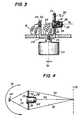
- the subassembly 28includes an elongated hollow tube 30, a laser diode 32 fixedly mounted at one axial end region of the tube 30, a lens barrel 34 mounted at the opposite axial end region of the tube 30, and a focusing lens 36 mounted within the barrel (see FIG.3).
- the focusing lens 36is preferably a plano-convex lens, but may be spherical, convex or cylindrical as well.
- the barrel 34has an end wall formed with an aperture stop 38 which is an opening extending through the end wall.
- the barrel 34is mounted for longitudinal telescoping movement within and along the tube 30.
- the lens 36is situated adjacent the end wall of the barrel and is mounted for joint movement with the barrel.
- a coil spring 37(see FIG. 3) is located within and extends along the barrel and tube, and has one coil end bearing against the diode, and another coil end bearing against a planar side of the lens. The spring urges the lens against the end wall having the aperture stop, thereby fixedly locating the lens relative to the aperture stop.
- the subassembly 28includes a solid-state laser diode 32 operative for propagating and generating an incident laser beam, either in the invisible or visible light range, and the combination of a focusing lens and an aperture stop together operative for focusing the laser beam to have a beam cross-section or beam spot of a certain waist size within a range of working distances relative to the housing 12.
- the focused beampasses through the aperture stop 38 and through a scan window 40 on the housing in the vicinity of a reference plane located exteriorly of the housing within the range of working distances along an outgoing optical path.
- a portion of the light reflected off the symbolpasses along a return path through a second window 42 on the housing in the direction of arrow B to a photodetector 44 for detecting the variable intensity of the returning portion of the reflected laser light over a field of view, and for generating an electrical analog signal indicative of the detected variable light intensity.
- the photodetector 44is stationarily mounted on the printed circuit board 46.
- Printed circuit boards 48 and 50 at either side of board 46contain signal processing circuitry 52 and microprocessor control circuitry 53 for converting the analog electrical signal to a digital signal, and for processing the digital signal to data descriptive of the symbol being read.
- a two-part multi-wire plug-in cable connector 54has one part electrically connected to the signal processing and microprocessor control circuitry and another part electrically connected to a flexible multi-wire cable 54' connected to a display 55 and a keyboard 56.
- a rechargeable battery pack 58supplies power to the laser diode and the electrical circuitry in the housing. By moving only the laser diode and the optical component relative to the stationary photodetector, power from the battery pack is conserved.
- Means for initiating readingmay advantageously include a trigger 60 mounted on the housing 12.
- the triggerextends in part outwardly of the housing to be manually actuated by a user who is holding the housing 12 in his hand.
- the triggeris operatively connected through trigger switch 62 and actuates the laser diode 32, the motor 20, the photodetector 44, the signal processing circuitry 52 and the control circuitry 53 to initiate a reading of the symbol.
- the triggeris actuated once for each symbol to be read, each symbol in its respective turn.
- the control circuitryterminates the reading of the symbol and deactuates the previously actuated components in the housing and readies the system for the next symbol.
- FIG. 2illustrates the various electrical, mechanical and optical components assembled as a modular unit prior to mounting in the upper half 16 of the housing 12 of FIGs. 1A, 1B.
- the oscillating motor 20has an output shaft 22 on which a generally U-shaped support 26 is mounted.
- a laser/optics subassembly 28is mounted on one leg 64 of the support.
- a photodetector 44is mounted on another leg 66 of the support.
- Coiled tensile wire groups 68, 70connect the diode 32 and the photodetector 44 to the non-illustrated electrical circuitry on printed circuit board 48. Although coiled wires have been illustrated, other types of electrical connectors, e.g. flat cable, could be employed.
- a collecting lens 72is mounted on leg 64 and coaxially surrounds subassembly 28.
- the lens 72, the subassembly 28 and the photodetector 44all have a common boresight or optical axis 74 along which the optical and return paths are co-linear, and are all oscillatable as a unit in alternate circumferential directions (see double-headed arrow 76 in FIG. 4) about the axis along which shaft 22 extends.
- FIG. 4The operation of the arrangement of FIG. 3 is schematically shown in FIG. 4.
- An incident laser beamis emitted from the subassembly 28. In a center position, this beam is directed along optical axis 74 to a reference plane 78 at which a symbol is located. Light is scattered in all directions from the symbol. A portion of the reflected light, as represented by light rays 79,81, is incident on collecting lens 72, e.g. a Fresnel lens, and focused onto an inlet of the photodetector 44. The inlet may be round, square or rectangular (see FIG.6). As the unit turns in the direction of either arrow 76, the beam spot at the reference plane likewise moves across the symbol. The returning light is always focused onto the inlet of the photodetector.
- collecting lens 72e.g. a Fresnel lens
- FIG. 3The arrangement of FIG. 3 is retro-reflective because not only the incident beam, but also the field of view of the photodetector, are being simultaneously scanned across the symbol.
- FIGS. 1A, 1B arrangementis a so-called "flying spot” scanner, because only the incident beam is being swept across the symbol, the photodetector being stationary.
- the oscillating motor 20has an output shaft 22 on which a support 80 is mounted. Rather than being U-shaped like support 26, support 80 is L-shaped and has an upright leg 82.
- a laser/optics subassembly 28is mounted on leg 82.
- a photodetector 44is stationarily mounted on printed circuit board 46.
- Coiled tensile wire group 68interconnects the diode 32 and electrical circuitry on board 46.
- Collecting lens 72is mounted on leg 82 in a coaxially surrounding relationship with subassembly 28. The lens 72 and the subassembly 28 turn as a unit in either direction of double-headed arrow 76, whereas photodetector 44, in contrast to the previous embodiment of FIG. 3, is stationary.
- an incident light beam emitted from subassembly 28is directed in one end-limiting position along optical axis 84 to impinge on a symbol located at the reference plane 78, whereupon a portion of the reflected light, as represented by light rays 86, 88, is incident on collecting lens 72 and focused at one end 90 of an elongated slot-like inlet 92 of the photodetector 44, best shown in FIG. 6.
- the collected portion of reflected lightis focused at an opposite end 94 of the inlet 92. Between end-limiting portions, the collected, focused light travels lengthwise along the inlet 92.
- FIGs. 5-7 arrangementis another retro-reflective arrangement, because both the incident beam is being swept across the symbol, and the field of view of the photodetector is likewise being swept across the symbol at the same time due to the movement of the collecting lens.
- the collecting lenscould be eliminated by having the output power of the light source sufficiently high.
- FIG. 8shows an arrangement for generating a scan pattern extending in more than one direction over the symbol.
- motor 20repetitively drives output shaft 22, support 26 and laser/optics subassembly 28 in the alternate directions indicated by arrows 76.
- Tensile wire group 68interconnects the diode 32 with a low voltage power supply 96.
- the motor and its superstructureare mounted on a horizontal platform 98 of a base 100.
- the basehas additional platforms for other components.
- horizontal platform 102supports a collecting lens 104.
- Platform 106supports a photodetector 44 on an upper surface, as well as a printed circuit board 108 on which signal processing circuitry is mounted on a lower surface.
- a second motor 20' identical to motor 20is mounted on a vertical platform 110 and has an output shaft 22' which is at right angles to shaft 22.
- a planar mirror 112is mounted at one end of shaft 22', thereby being similar to the scanning element described in U.S. Pat. No. 4,496,831.
- the motor 22'drives the mirror 112 in alternate circumferential directions as indicated by double-headed arrow 114.
- FIG. 9shows an arrangement wherein the wire joints between the diode and its power supply are positioned in the immediate vicinity of the shaft, thereby minimizing the stress forces acting to weaken such joints and maximizing the working lifetime of the arrangement.
- a support block 26"is mounted on the shaft 22, but off to one side of the shaft.
- the subassembly 28is mounted on the block 26".
- a printed circuit board 116is mounted at the side of the block facing the shaft 22.
- the board 116has three printed conductive strips 118 a , 118 b , 118 c extending along the board 116.
- the laser diode. 32has a first group of wires 68 connected to respective ends of the strips; and a second group of wires 120 is connected to respective opposite ends of the strips and to the power supply 96.
- the subassembly 28, the board 116 and the first group of wires 68are jointly oscillated.
- the second group of wires 120is subjected to stress forces, but, as shown, the wire joints at the opposite ends of the strips are immediately adjacent the shaft 22 so that the magnitude of the stress forces is much reduced as compared to the situation wherein the first group of wires 68 were directly connected to the power supply 96.
- the laser diode/optics subassembly 28 by itself or with the photodetector 44is turned about an axis to effect a scanning or sweeping action. It is also possible to move the focusing lens 36 either by itself or with the aperture stop 28 relative to the diode 32 in a plane generally parallel to the light-emitting outlet of the diode.
- the laser diode 32is stationarily mounted on a support 122.
- the diode 32emits along optical axis 130 a wide-angle fan-shaped laser beam schematically represented by light rays 124, 126.
- the fan-shaped beamdiverges at different angles in both orthogonal planes extending parallel to the plane of the diode outlet and perpendicular to the optical axis 130.
- the focusing lens 36is mounted in a holder 128 at a fixed distance of focal length F as measured along axis 130, from the diode.
- the holderhas an opening centered on the axis 130, the opening serving as the aperture stop 38.
- a voice coil 138surrounds the holder 128 inside the casing 132 and is bounded by north N and south S poles of the casing.
- the holder and, in turn, the lens and the aperture stopare made to jointly reciprocate back and forth in a plane perpendicular to axis 130 due to electromagnetic attraction and repulsion forces generated at the coil.
- Dthe deflection of the lens and aperture stop as measured from the axis 130 to one end-limiting position
- FIG. 12shows an alternate to the convoluted springs 134, 136.
- a so-called “spider” spring 142 having curved legs 144could also be used.
- FIG. 13shows another arrangement for reciprocally shifting the lens 36 and aperture stop 38 in a plane parallel to the plane of the outlet of the diode 32.
- the lens 36is mounted on a bridge support 150 which spans the distance between, and is carried by, two center legs 152, 154 of E-shaped leaf springs 156, 158.
- Outer legs 160, 162 of spring 156 and outer legs 164, 166 of spring 158are stationarily connected to an overhead support frame 170.
- the bridge support 150has an opening centered on optical axis 130, the opening serving as the aperture stop 38.
- a permanent magnet strip 172having a north N pole at one end and a south S pole at an opposite end is carried by the bridge support.
- a pair of driving coils 174, 176surrounds each pole.
- each driving coilis electrically energized. Electromagnetic attraction and repulsion forces are generated by magnetic interaction between the coils and the poles N, S, thereby causing the bridge support to be reciprocally shifted in a plane perpendicular to axis 130.
- FIG. 13shows this arrangement in a center, non-shifted position.
- the FIG. 16 arrangement described belowillustrates a shifted position. It will be noted that only the upper ends of the center legs of the E-springs are displaced. A substantially constant distance between the lens and aperture stop combination and the diode is maintained. Proper laser beam focus at the reference plane is thus maintained thereat.
- the beam spotis moved along an arc around a center of curvature at the lens. It is possible, by having unequal lengths or stiffnesses in the legs of the springs, to have the beam spot moved in a desired manner across the symbol. For example, the spot can be moved in a straight line.
- FIG. 16shows an arrangement identical to FIG. 13, but, instead of the magnetic strip 172, a plate 180 is connected to the bridge support.
- the plate 180has a lug 182 to which a drive bar 184 is pivotably connected.
- the bar 184can be connected to a pure mechanical drive, an electro-mechanical drive, or a piezo-electric substrate, i.e. a transducer operative for converting electrical to mechanical energy, to effect the reciprocal movement.
- the center legs 152, 154 of the springscan be made of one bi-metallic material while the outer legs are made of another bi-metallic material. Heating all the legs would cause the center legs to be displaced relative to the outer legs.
- FIG. 17Another approach is shown in FIG. 17, wherein the aperture stop 38 is held stationary, and only the focusing lens 36 is reciprocally shifted. Since the laser beam does not pass through the center of the lens 36 when the lens is shifted off axis, the deflection or scan angle A is amplified. Light passing through the lens off the axis 130 has more optical aberrations, but they have not been found to be significant for bar code reading applications.
- the low mass of the moving structurei.e. the lens alone; the lens and aperture stop together; the lens, aperture stop and diode jointly; and the lens, aperture stop, diode and. photodetector jointly, enables the system to operate at resonance for low power applications, as well as off resonance. Very high scanning speeds on the order of 40 scans per second and more are obtainable due to the low mass of the moving structure.
- FIG. 18Yet another approach is shown in FIG. 18, wherein the focusing lens 36 is held stationary, and only the aperture stop 38 is reciprocally shifted.
- the aperture stop 38is formed as an opening in a top wall 200 that is positioned by side walls 202, 204 at a distance from a support 206 on which the laser diode 32 is mounted.
- the apertured top wall 200is shiftable to the left and to the right, as indicated by the phantom lines, by any reciprocating drive, e.g. an electromagnet or piezo-electric drive.
- Bimorph materialcan also be used for the walls 200, 202, 204 to move the aperture stop in a plane in front of the lens 36.
- a finger-held housing 264 containing the scanning arrangementis supported on at least one of the user's fingers 266 by a ring-like support 268.
- the outgoing light beampasses over the user's fingers and, as before, reading can be automatically or manually initiated.
Landscapes
- Physics & Mathematics (AREA)
- Engineering & Computer Science (AREA)
- Electromagnetism (AREA)
- General Physics & Mathematics (AREA)
- Theoretical Computer Science (AREA)
- Health & Medical Sciences (AREA)
- General Health & Medical Sciences (AREA)
- Toxicology (AREA)
- Artificial Intelligence (AREA)
- Computer Vision & Pattern Recognition (AREA)
- Business, Economics & Management (AREA)
- Microelectronics & Electronic Packaging (AREA)
- Computer Networks & Wireless Communication (AREA)
- Accounting & Taxation (AREA)
- Strategic Management (AREA)
- General Business, Economics & Management (AREA)
- Mechanical Optical Scanning Systems (AREA)
- Facsimile Scanning Arrangements (AREA)
- Optical Radar Systems And Details Thereof (AREA)
- Laser Beam Printer (AREA)
- Gyroscopes (AREA)
- Apparatus For Radiation Diagnosis (AREA)
- Vehicle Body Suspensions (AREA)
Abstract
Description
Claims (4)
- A light scanningarrangement for reading indicia having parts of differentlight reflectivity, the arrangement comprising:wherein all of said components are mounted togetherin a common housing to constitute a compact,lightweight scan module;(A) a light source component for emitting alight beam;(B) an optical component for optically modifyingand directing the light beam along an optical pathtoward indicia located in the vicinity of a referenceplane exteriorly of the arrangement;(C) a photodetector component having a fieldof view and operative for detecting at least a portionof light of variable intensity reflected off the indicia,and for generating an electrical signal indicative of thedetected light intensity;(D) a scanning component for scanning at leastone of the light beam and the field of view;(E) an electrical connecting component for conductingthe electrical signal away from the photodetectorcomponent;
characterized in thatthe housing is provided with means adapted tosupport the housing on a finger of the userof the scanning arrangement. - The arrangement as recited in claim 1,characterized in that the supporting means includes a ring thatat least partially encircles the user's finger.
- The scanning arrangement of claim 1 or 2, wherein said lightsource component and said scanning component areimplemented on a single semiconductor and/or electroopticalsubstrate.
- The scanning arrangement of one of claims 1 to 3,further comprising:a window in said housing transmitting the light beam directed toward said indicia and the light reflected from said indicia.
Applications Claiming Priority (3)
| Application Number | Priority Date | Filing Date | Title |
|---|---|---|---|
| US699417 | 1991-05-13 | ||
| US07/699,417US5191197A (en) | 1988-05-11 | 1991-05-13 | Arm mounted scanner actuatable by hand movement |
| EP19920106285EP0513530A3 (en) | 1991-05-13 | 1992-04-10 | Mirrorless scanners with movable laser, optical and sensor components |
Related Parent Applications (1)
| Application Number | Title | Priority Date | Filing Date |
|---|---|---|---|
| EP92106285.7Division | 1992-04-10 |
Publications (3)
| Publication Number | Publication Date |
|---|---|
| EP0930579A2 EP0930579A2 (en) | 1999-07-21 |
| EP0930579A3 EP0930579A3 (en) | 1999-07-28 |
| EP0930579B1true EP0930579B1 (en) | 2002-07-10 |
Family
ID=24809229
Family Applications (2)
| Application Number | Title | Priority Date | Filing Date |
|---|---|---|---|
| EP19920106285CeasedEP0513530A3 (en) | 1991-05-13 | 1992-04-10 | Mirrorless scanners with movable laser, optical and sensor components |
| EP99101022AExpired - LifetimeEP0930579B1 (en) | 1991-05-13 | 1992-04-10 | Ringscanner |
Family Applications Before (1)
| Application Number | Title | Priority Date | Filing Date |
|---|---|---|---|
| EP19920106285CeasedEP0513530A3 (en) | 1991-05-13 | 1992-04-10 | Mirrorless scanners with movable laser, optical and sensor components |
Country Status (9)
| Country | Link |
|---|---|
| US (2) | US5191197A (en) |
| EP (2) | EP0513530A3 (en) |
| JP (1) | JP2717043B2 (en) |
| KR (1) | KR100208465B1 (en) |
| AT (1) | ATE220467T1 (en) |
| AU (1) | AU650833B2 (en) |
| CA (1) | CA2063348C (en) |
| DE (1) | DE69232678T2 (en) |
| ES (1) | ES2177144T3 (en) |
Families Citing this family (126)
| Publication number | Priority date | Publication date | Assignee | Title |
|---|---|---|---|---|
| US5892971A (en)* | 1986-08-08 | 1999-04-06 | Norand Corporation | Portable data processing device having an indicia reader and a multi-tasking operating system capable of executing battery monitoring instructions while concurrently executing application programs |
| US6621942B1 (en)* | 1989-09-29 | 2003-09-16 | Intermec Ip Corp. | Data capture apparatus with handwritten data receiving component |
| US5471042A (en)* | 1988-05-11 | 1995-11-28 | Symbol Technologies, Inc. | Handheld data entry terminal having dual trigger switches |
| US5479002A (en)* | 1988-05-11 | 1995-12-26 | Symbol Technologies, Inc. | Bar code scanner with scanning beam and/or field of view adjustable about three mutually orthogonal axes |
| US5412193A (en)* | 1988-05-11 | 1995-05-02 | Symbol Technologies, Inc. | Mobile point-of-sale supermarket checkout system |
| US5410140A (en)* | 1988-05-11 | 1995-04-25 | Symbol Technologies, Inc. | Mirrorless ring mounted miniature optical scanner |
| US5374817A (en)* | 1988-05-11 | 1994-12-20 | Symbol Technologies, Inc. | Pre-objective scanner with flexible optical support |
| US5514861A (en)* | 1988-05-11 | 1996-05-07 | Symbol Technologies, Inc. | Computer and/or scanner system mounted on a glove |
| US5665954A (en)* | 1988-10-21 | 1997-09-09 | Symbol Technologies, Inc. | Electro-optical scanner module having dual electro-magnetic coils |
| US5530619A (en)* | 1989-06-07 | 1996-06-25 | Norand Corporation | Hand-held data capture system with interchangeable modules and side-mounted function key |
| US5305181A (en)* | 1989-05-15 | 1994-04-19 | Norand Corporation | Arm or wrist mounted terminal with a flexible housing |
| US5539193A (en)* | 1989-06-07 | 1996-07-23 | Norand Corporation | Modular hand-held data entry system |
| US6244512B1 (en)* | 1989-06-08 | 2001-06-12 | Intermec Ip Corp. | Hand-held data capture system with interchangeable modules |
| US5587577A (en)* | 1989-06-08 | 1996-12-24 | Norand Corporation | Modular scanner with hand-held data terminal |
| US5422469A (en)* | 1989-10-30 | 1995-06-06 | Symbol Technologies, Inc. | Fiber optic barcode readers using purely mechanical scanner oscillation |
| US5404001A (en)* | 1992-10-08 | 1995-04-04 | Bard; Simon | Fiber optic barcode reader |
| US5543610A (en)* | 1989-10-30 | 1996-08-06 | Symbol Technologies, Inc. | Compact bar code scanning arrangement |
| US5861615A (en) | 1990-05-08 | 1999-01-19 | Symbol Technologies, Inc. | Palm scanner |
| US5756982A (en)* | 1990-09-11 | 1998-05-26 | Metrologic Instruments, Inc. | Body-wearable automatic laser scanner with power-conserving control subsystem |
| US5610387A (en)* | 1992-05-15 | 1997-03-11 | Symbol Technologies, Inc. | Portable optical scanning system worn by a user for reading indicia of differing light reflectivity |
| US6036093A (en)* | 1992-04-23 | 2000-03-14 | Intermec Ip Corp. | Modular scanner with hand-held data terminal |
| US6036098A (en)* | 1992-05-15 | 2000-03-14 | Symbol Technologies, Inc. | Miniature scan element operably connected to a personal computer interface card |
| JP3389270B2 (en)* | 1992-05-15 | 2003-03-24 | シンボル テクノロジイズ インコーポレイテッド | Small barcode scanner |
| US5708262A (en)* | 1992-05-15 | 1998-01-13 | Symbol Technologies, Inc. | Miniature high speed scan element mounted on a personal computer interface card |
| USD348260S (en) | 1992-05-21 | 1994-06-28 | Ncr Corporation | Bar code scanner |
| KR940001000A (en)* | 1992-06-12 | 1994-01-10 | 시모야마 도시로오 | Adaptive bar code scanner |
| USD342245S (en) | 1992-07-02 | 1993-12-14 | Symbol Technologies, Inc. | Optical scanner |
| US6105871A (en)* | 1992-07-16 | 2000-08-22 | Telxon Corporation | Portable bar code scanner apparatus |
| US5324925A (en)* | 1992-09-25 | 1994-06-28 | Norand Corporation | Hand-held data terminal and communicator |
| US5329106A (en)* | 1992-10-02 | 1994-07-12 | Psc, Inc. | Handle-less bar code scanning system |
| US5371348A (en)* | 1992-10-16 | 1994-12-06 | Khyber Technologies Corporation | Portable device for handsfree data entry with variably-positionable display/scanner module detachable for handheld use |
| US5380994A (en)* | 1993-01-15 | 1995-01-10 | Science And Technology, Inc. | Microcomputer adapted for inventory control |
| US5675138A (en)* | 1993-04-02 | 1997-10-07 | Psc, Inc. | Non-contact actuated trigger apparatus for bar code laser scanner |
| DE9307114U1 (en)* | 1993-05-11 | 1993-08-05 | Systec Ausbausysteme Gmbh, 82223 Eichenau | Information device for shopping carts |
| JP3181781B2 (en)* | 1993-05-19 | 2001-07-03 | 三菱電機株式会社 | Electric vehicle control device |
| US6853293B2 (en) | 1993-05-28 | 2005-02-08 | Symbol Technologies, Inc. | Wearable communication system |
| US6811088B2 (en)* | 1993-05-28 | 2004-11-02 | Symbol Technologies, Inc. | Portable data collection system |
| GB2282906B (en)* | 1993-10-13 | 1996-11-06 | Dataquill Ltd | Data enty systems |
| JPH07114630A (en)* | 1993-10-19 | 1995-05-02 | Matsushita Electric Ind Co Ltd | Small information terminal device with image processing function |
| CA2132646A1 (en)* | 1993-10-25 | 1995-04-26 | Jerome Swartz | Integrated scanner on a common substrate |
| FR2717812B1 (en)* | 1994-03-28 | 1996-05-10 | Rhone Poulenc Rorer Sa | Indeno [1,2-e] pyrazine-4-ones, their preparation and the drugs containing them. |
| US5898161A (en)* | 1994-08-29 | 1999-04-27 | Symbol Technologies, Inc. | Wrist-mounted optical scanning and pointing systems |
| EP0700012B1 (en)* | 1994-08-29 | 2001-05-09 | Symbol Technologies, Inc. | A portable optical scanning system worn by a user for reading indicia of differing light reflectivity |
| JP3379837B2 (en)* | 1994-10-27 | 2003-02-24 | 富士通株式会社 | Optical reader |
| JP3495122B2 (en)* | 1995-01-11 | 2004-02-09 | 富士通株式会社 | Portable terminal device |
| CA2166508C (en)* | 1995-02-01 | 2008-04-01 | Simon Bard | Portable optical scanning and pointing systems |
| US5621199A (en)* | 1995-04-03 | 1997-04-15 | Datalogic, Inc. | RFID reader |
| US5576530A (en)* | 1995-05-11 | 1996-11-19 | Universal Data Incorporated | Portable data terminal including a scanning head that is secured to the terminal in a manner that allows the scanning head to be positioned in opposite orientations |
| USD369786S (en) | 1995-05-11 | 1996-05-14 | Universal Data Incorporated | Portable data terminal with rotatable head |
| US6505776B1 (en)* | 1995-06-07 | 2003-01-14 | Metrologic Instruments, Inc. | System for storing, accessing and displaying html-encoded documents relating to an object being worked upon in a work environment by a human operator wearing a wireless http-enabled client system equipped with a code symbol reader programmed to read a url-encoded symbol on the object, access said html-encoded documents from http-enabled information servers connected to an information network, and display same for review while working said object |
| USD377345S (en)* | 1995-07-03 | 1997-01-14 | Psc Inc. | Optical scanner |
| USD377348S (en)* | 1995-07-03 | 1997-01-14 | Psc Inc. | Optical scanner |
| USD370478S (en) | 1995-07-13 | 1996-06-04 | Symbol Technologies, Inc. | Combined optical scanner and portable terminal |
| US5610386A (en)* | 1995-07-17 | 1997-03-11 | Symbol Technologies, Inc. | Portable optical scanning system including ring having breakaway element |
| US5796088A (en)* | 1995-08-15 | 1998-08-18 | Teletransactions, Inc. | Hand held portable bar code dataform reader having a rotatable reader module portion |
| US5657201A (en)* | 1995-11-06 | 1997-08-12 | Teletransactions, Inc. | Portable data collection terminal including arm mounting assembly |
| US7470244B2 (en)* | 1996-01-26 | 2008-12-30 | Harrison Jr Shelton E | Flexion-discouraging splint system, method and device |
| JP3793600B2 (en)* | 1996-02-20 | 2006-07-05 | 株式会社オプトエレクトロニクス | Optical pattern reader |
| USD385855S (en)* | 1996-08-06 | 1997-11-04 | Xybernaut Corporation | Body-worn, portable computer |
| US6330244B1 (en)* | 1996-09-05 | 2001-12-11 | Jerome Swartz | System for digital radio communication between a wireless lan and a PBX |
| US5808289A (en)* | 1996-09-30 | 1998-09-15 | Telxon Corporation | Arm mounted portable data collection device with rotatable and detachable dataform reader module |
| US6764012B2 (en)* | 1997-02-10 | 2004-07-20 | Symbol Technologies, Inc. | Signaling arrangement for and method of signaling in a wireless local area network |
| US6338432B1 (en)* | 1997-02-19 | 2002-01-15 | Opticon Inc | Optical pattern reading apparatus with movable optical unit |
| US6976626B2 (en)* | 1997-09-16 | 2005-12-20 | Metrologic Instruments, Inc. | Wireless bar code symbol driven portable data terminal (PDT) system adapted for single handed operation |
| US6213619B1 (en) | 1997-10-14 | 2001-04-10 | Sun Yu | Wrist mounted light |
| US6098886A (en)* | 1998-01-21 | 2000-08-08 | Symbol Technologies, Inc. | Glove-mounted system for reading bar code symbols |
| USD411179S (en) | 1998-02-02 | 1999-06-22 | Xybernaut Coporation | Mobile body-worn computer |
| NL1010088C2 (en)* | 1998-09-14 | 2000-03-15 | Scantech Bv | Barcode reading device. |
| DE19853899C2 (en)* | 1998-11-23 | 2001-11-22 | Horst Spanyar | Device for electrically connecting a cell phone to a keyboard |
| USD460068S1 (en) | 2000-03-27 | 2002-07-09 | Symbol Technologies, Inc. | Portable handheld terminal housing |
| US6732934B2 (en)* | 2001-01-12 | 2004-05-11 | Symbol Technologies, Inc. | Escorted shopper system |
| USD455746S1 (en) | 2001-05-22 | 2002-04-16 | Xybernaut Corporation | Wearable computer |
| USD461471S1 (en) | 2001-07-17 | 2002-08-13 | Xybernaut Corporation | Wearable computer |
| US7185818B2 (en)* | 2003-12-29 | 2007-03-06 | Symbol Technologies, Inc. | Rotatable/removeable keyboard |
| US7746511B2 (en)* | 2004-04-23 | 2010-06-29 | Symbol Technologies, Inc. | Scan head rotation at different optimum angles |
| USD599798S1 (en) | 2004-09-10 | 2009-09-08 | Hand Held Products, Inc. | Hand held computer device |
| US7446753B2 (en) | 2004-09-10 | 2008-11-04 | Hand Held Products, Inc. | Hand held computer device |
| GB2426099B (en)* | 2004-09-30 | 2007-05-09 | Motorola Inc | Wearable imaging device |
| US20060166720A1 (en)* | 2004-10-19 | 2006-07-27 | Herman Dixon | Universal wrist worn holder for cellular phones |
| US20090080037A1 (en)* | 2004-10-19 | 2009-03-26 | Kenichi Hayashi | Condenser Lens and Optical Scanning Device |
| EP1872301A1 (en)* | 2005-04-21 | 2008-01-02 | Sygade Solutions (Proprietary) Limited | A reader and a method of activating a reader |
| US20060285009A1 (en)* | 2005-06-20 | 2006-12-21 | Jin-Sheng Lai | Illuminating assembly for image-taking device |
| US7810504B2 (en)* | 2005-12-28 | 2010-10-12 | Depuy Products, Inc. | System and method for wearable user interface in computer assisted surgery |
| US20070201861A1 (en)* | 2006-02-27 | 2007-08-30 | Coulman Betty A | Imaging device |
| US20080129532A1 (en)* | 2006-11-30 | 2008-06-05 | David Bellows | System and Method for Activating a Mobile Device |
| USD601151S1 (en)* | 2007-01-31 | 2009-09-29 | Symbol Technologies, Inc. | Bottom portion of a finger mounted device |
| USD601557S1 (en) | 2007-08-06 | 2009-10-06 | Data Ltd., Inc. | Tablet computer |
| JP2009104376A (en)* | 2007-10-23 | 2009-05-14 | Well Cat:Kk | Information terminal device |
| USD654499S1 (en) | 2009-06-09 | 2012-02-21 | Data Ltd., Inc. | Tablet computer |
| USD635568S1 (en) | 2009-06-09 | 2011-04-05 | Data Ltd., Inc. | Tablet computer |
| USD638834S1 (en) | 2009-10-05 | 2011-05-31 | Data Ltd., Inc. | Tablet computer |
| USD649272S1 (en) | 2010-12-03 | 2011-11-22 | Surefire, Llc | Wearable lighting device |
| US9155168B2 (en) | 2010-12-03 | 2015-10-06 | Surefire, Llc | Wearable lighting device |
| USD690296S1 (en) | 2011-02-01 | 2013-09-24 | Data Ltd., Inc. | Tablet computer |
| US8292184B2 (en)* | 2011-03-03 | 2012-10-23 | Turbovich Irit | Barcode scanner |
| USD690855S1 (en) | 2012-01-13 | 2013-10-01 | Surefire, Llc | Wearable lighting device |
| USD676991S1 (en) | 2012-01-13 | 2013-02-26 | Surefire, Llc | Wearable lighting device |
| USD758628S1 (en) | 2012-11-05 | 2016-06-07 | Surefire, Llc | Wearable lighting device |
| USD758629S1 (en) | 2012-11-05 | 2016-06-07 | Surefire, Llc | Wearable lighting device |
| US8972283B2 (en) | 2013-01-13 | 2015-03-03 | Retail Technologies Corporation | Wearable mobile scanner system with mobile tablet having a mobile POS and enterprise resource planning application for POS customer order fulfillment and in store inventory management for retail establishment |
| US9092765B2 (en) | 2013-01-13 | 2015-07-28 | Retail Technologies Corporation | Wearable mobile scanner system with mobile tablet having a mobile POS and enterprise resource planning application for POS customer order fulfillment and method in store inventory management for retail establishment |
| US9224027B2 (en)* | 2014-04-01 | 2015-12-29 | Hand Held Products, Inc. | Hand-mounted indicia-reading device with finger motion triggering |
| US10198030B2 (en)* | 2014-05-15 | 2019-02-05 | Federal Express Corporation | Wearable devices for courier processing and methods of use thereof |
| TWD171525S (en)* | 2014-06-24 | 2015-11-01 | 鴻海精密工業股份有限公司 | Ring reader |
| US9752762B1 (en)* | 2014-07-08 | 2017-09-05 | Renzie M. Poe, III | Rechargeable wrist-mounted work light |
| DE102015017430B3 (en) | 2014-10-11 | 2023-08-10 | Workaround Gmbh | Workwear unit, glove, sensor module and structural unit |
| US9639732B2 (en) | 2015-01-12 | 2017-05-02 | Symbol Technologies, Llc | Apparatus and system for operating a handheld barcode scanner in a presentation mode |
| US9507974B1 (en)* | 2015-06-10 | 2016-11-29 | Hand Held Products, Inc. | Indicia-reading systems having an interface with a user's nervous system |
| USD832844S1 (en)* | 2016-07-11 | 2018-11-06 | Symbol Technologies, Llc | Wearable data capture device |
| DE102016123093A1 (en)* | 2016-11-30 | 2018-05-30 | Workaround Gmbh | Garment, method of making a glove and glove set |
| USD865773S1 (en)* | 2017-04-28 | 2019-11-05 | Hand Held Products, Inc. | Electronic device with attachment apparatus |
| USD859412S1 (en)* | 2017-08-18 | 2019-09-10 | Practech, Inc. | Wearable or handheld hybrid smart barcode scanner |
| JP7139770B2 (en)* | 2018-02-13 | 2022-09-21 | 株式会社デンソーウェーブ | Information reader |
| US10817689B2 (en)* | 2017-12-21 | 2020-10-27 | Datalogic IP Tech, S.r.l. | Systems and methods for a scan engine coupled to a finger mount |
| US11188122B2 (en)* | 2017-12-21 | 2021-11-30 | Datalogic Usa Inc. | Low-profile wearable scanning device |
| KR102124019B1 (en)* | 2018-05-09 | 2020-06-17 | (주)에스피에스 | Smart watch with recognition device that can be combined and removed |
| KR102147221B1 (en)* | 2018-05-10 | 2020-08-24 | (주)에스피에스 | Smart watch with sensors and recognition method using the same |
| DE102018112945B4 (en) | 2018-05-30 | 2022-03-03 | Workaround Gmbh | Glove |
| US10344924B1 (en)* | 2018-07-01 | 2019-07-09 | Joseph Ganahl | Multibeam lighting system |
| USD944814S1 (en)* | 2019-01-31 | 2022-03-01 | Standard Cyborg, Inc | Mobile communications device attachment with mirror |
| US10789436B1 (en) | 2019-07-19 | 2020-09-29 | Zebra Technologies Corporation | Data capture device |
| USD918914S1 (en)* | 2019-07-19 | 2021-05-11 | Zebra Technologies Corporation | Data capture device |
| USD937267S1 (en) | 2019-12-26 | 2021-11-30 | Zebra Technologies Corporation | Data capture device |
| DE102021126552B4 (en) | 2021-10-13 | 2025-09-04 | Workaround Gmbh | Glove and wearable sensor device comprising a glove and an electronic module |
| US12093088B2 (en)* | 2022-06-06 | 2024-09-17 | Apple Inc. | Modular light assembly for a wearable device |
| US12248842B2 (en)* | 2022-12-09 | 2025-03-11 | Rgis International Holdings, Llc | Ring scanner with counting function and method thereof |
Citations (3)
| Publication number | Priority date | Publication date | Assignee | Title |
|---|---|---|---|---|
| US4766299A (en)* | 1986-03-28 | 1988-08-23 | Spectra-Physics, Inc. | Hand-mounted bar code reader |
| EP0341717A2 (en)* | 1988-05-11 | 1989-11-15 | Symbol Technologies, Inc. | Mirrorless scanners with movable lase, optical and sensor components |
| EP0373935A2 (en)* | 1988-12-15 | 1990-06-20 | Ncr Corporation | Hand-held bar code reader |
Family Cites Families (23)
| Publication number | Priority date | Publication date | Assignee | Title |
|---|---|---|---|---|
| US4251798A (en)* | 1978-05-31 | 1981-02-17 | Symbol Technologies | Portable laser scanning arrangement for and method of evaluating and validating bar code symbols |
| US4496831A (en)* | 1980-02-29 | 1985-01-29 | Symbol Technologies, Inc. | Portable laser scanning system and scanning methods |
| US4387297B1 (en)* | 1980-02-29 | 1995-09-12 | Symbol Technologies Inc | Portable laser scanning system and scanning methods |
| US4369361A (en)* | 1980-03-25 | 1983-01-18 | Symbol Technologies, Inc. | Portable, stand-alone, desk-top laser scanning workstation for intelligent data acquisition terminal and method of scanning |
| US4758717A (en)* | 1982-01-25 | 1988-07-19 | Symbol Technologies, Inc. | Narrow-bodied, single-and twin-windowed portable laser scanning head for reading bar code symbols |
| US4409470A (en)* | 1982-01-25 | 1983-10-11 | Symbol Technologies, Inc. | Narrow-bodied, single-and twin-windowed portable laser scanning head for reading bar code symbols |
| US4560862A (en)* | 1983-04-26 | 1985-12-24 | Skan-A-Matic Corp. | System for optical scanning over a large depth of field |
| JPS60168282A (en)* | 1984-02-13 | 1985-08-31 | Sanden Corp | Bar code reader |
| US4743773A (en)* | 1984-08-23 | 1988-05-10 | Nippon Electric Industry Co., Ltd. | Bar code scanner with diffusion filter and plural linear light source arrays |
| DE3687127T2 (en)* | 1985-02-28 | 1993-05-06 | Symbol Technologies Inc | PORTABLE SCAN HEAD WITH A LASER DIODE. |
| US4621189A (en)* | 1985-10-08 | 1986-11-04 | Telxon Corporation | Hand held data entry apparatus |
| US4850009A (en)* | 1986-05-12 | 1989-07-18 | Clinicom Incorporated | Portable handheld terminal including optical bar code reader and electromagnetic transceiver means for interactive wireless communication with a base communications station |
| US5059778A (en)* | 1986-09-29 | 1991-10-22 | Mars Incorporated | Portable data scanner apparatus |
| DE8712320U1 (en)* | 1987-09-11 | 1987-10-29 | TA Triumph-Adler AG, 8500 Nürnberg | Barcode reader |
| GB8807860D0 (en)* | 1988-04-05 | 1988-05-05 | Connaught Lab | Pertussis vaccine |
| US5015833A (en)* | 1988-10-31 | 1991-05-14 | Symbol Technologies, Inc. | Scan board module for laser scanners |
| US5023438A (en)* | 1988-11-26 | 1991-06-11 | Nitto Kohki Co., Ltd. | Portable data input apparatus with different display modes |
| JPH02144681A (en)* | 1988-11-26 | 1990-06-04 | Nitto Kohki Co Ltd | portable data entry device |
| US4930848A (en)* | 1989-01-26 | 1990-06-05 | Metrologic Instruments, Inc. | Portable laser scanner with integral scanner engine |
| US4939356A (en)* | 1989-05-02 | 1990-07-03 | Spectra-Physics, Inc. | Bar code scanner with asterisk scan pattern |
| EP0414452B1 (en)* | 1989-08-21 | 1995-07-19 | AT&T GLOBAL INFORMATION SOLUTIONS INTERNATIONAL INC. | Hand-held bar code reader |
| US5105070A (en)* | 1990-12-10 | 1992-04-14 | Ncr Corporation | Bar code scanning apparatus with rotating housing member |
| US5509778A (en)* | 1995-02-22 | 1996-04-23 | General Motors Corporation | Fuel pump for motor vehicle |
- 1991
- 1991-05-13USUS07/699,417patent/US5191197A/ennot_activeExpired - Lifetime
- 1992
- 1992-03-18CACA002063348Apatent/CA2063348C/ennot_activeExpired - Lifetime
- 1992-04-10EPEP19920106285patent/EP0513530A3/ennot_activeCeased
- 1992-04-10ESES99101022Tpatent/ES2177144T3/ennot_activeExpired - Lifetime
- 1992-04-10ATAT99101022Tpatent/ATE220467T1/enactive
- 1992-04-10DEDE69232678Tpatent/DE69232678T2/ennot_activeExpired - Lifetime
- 1992-04-10EPEP99101022Apatent/EP0930579B1/ennot_activeExpired - Lifetime
- 1992-05-07AUAU16109/92Apatent/AU650833B2/ennot_activeExpired
- 1992-05-11JPJP4116496Apatent/JP2717043B2/ennot_activeExpired - Fee Related
- 1992-05-11USUS07/881,280patent/US5306900A/ennot_activeExpired - Lifetime
- 1992-05-13KRKR1019920008079Apatent/KR100208465B1/ennot_activeExpired - Fee Related
Patent Citations (3)
| Publication number | Priority date | Publication date | Assignee | Title |
|---|---|---|---|---|
| US4766299A (en)* | 1986-03-28 | 1988-08-23 | Spectra-Physics, Inc. | Hand-mounted bar code reader |
| EP0341717A2 (en)* | 1988-05-11 | 1989-11-15 | Symbol Technologies, Inc. | Mirrorless scanners with movable lase, optical and sensor components |
| EP0373935A2 (en)* | 1988-12-15 | 1990-06-20 | Ncr Corporation | Hand-held bar code reader |
Also Published As
| Publication number | Publication date |
|---|---|
| JP2717043B2 (en) | 1998-02-18 |
| ATE220467T1 (en) | 2002-07-15 |
| EP0930579A2 (en) | 1999-07-21 |
| EP0513530A3 (en) | 1993-07-28 |
| DE69232678T2 (en) | 2003-03-13 |
| AU650833B2 (en) | 1994-06-30 |
| US5306900A (en) | 1994-04-26 |
| KR100208465B1 (en) | 1999-07-15 |
| AU1610992A (en) | 1992-11-19 |
| ES2177144T3 (en) | 2002-12-01 |
| JPH05143762A (en) | 1993-06-11 |
| CA2063348C (en) | 2002-12-03 |
| CA2063348A1 (en) | 1992-11-14 |
| EP0930579A3 (en) | 1999-07-28 |
| EP0513530A2 (en) | 1992-11-19 |
| US5191197A (en) | 1993-03-02 |
| DE69232678D1 (en) | 2002-08-14 |
Similar Documents
| Publication | Publication Date | Title |
|---|---|---|
| EP0930579B1 (en) | Ringscanner | |
| US5401948A (en) | Mirrorless scanners with movable laser, optical and sensor components | |
| CA1327850C (en) | Mirrorless scanners with movable laser, optical and sensor components | |
| US5250790A (en) | Hand-mounted scanner with automatic manual initiation of reading indicia | |
| US5661290A (en) | Scanner with flexibly supported light emitter | |
| US5744788A (en) | Voice-activated optical scanning system | |
| US5404001A (en) | Fiber optic barcode reader | |
| US5422469A (en) | Fiber optic barcode readers using purely mechanical scanner oscillation | |
| EP0590537B1 (en) | Scanning module | |
| EP0945819A2 (en) | One piece optical assembly for low cost optical scanner | |
| AU664207B2 (en) | Compact bar code scanning arrangement |
Legal Events
| Date | Code | Title | Description |
|---|---|---|---|
| PUAI | Public reference made under article 153(3) epc to a published international application that has entered the european phase | Free format text:ORIGINAL CODE: 0009012 | |
| PUAL | Search report despatched | Free format text:ORIGINAL CODE: 0009013 | |
| 17P | Request for examination filed | Effective date:19990120 | |
| AC | Divisional application: reference to earlier application | Ref document number:513530 Country of ref document:EP | |
| AK | Designated contracting states | Kind code of ref document:A2 Designated state(s):AT DE ES FR GB IT | |
| AK | Designated contracting states | Kind code of ref document:A3 Designated state(s):AT DE ES FR GB IT | |
| 17Q | First examination report despatched | Effective date:20000803 | |
| GRAG | Despatch of communication of intention to grant | Free format text:ORIGINAL CODE: EPIDOS AGRA | |
| GRAG | Despatch of communication of intention to grant | Free format text:ORIGINAL CODE: EPIDOS AGRA | |
| GRAH | Despatch of communication of intention to grant a patent | Free format text:ORIGINAL CODE: EPIDOS IGRA | |
| GRAH | Despatch of communication of intention to grant a patent | Free format text:ORIGINAL CODE: EPIDOS IGRA | |
| GRAA | (expected) grant | Free format text:ORIGINAL CODE: 0009210 | |
| AC | Divisional application: reference to earlier application | Ref document number:513530 Country of ref document:EP | |
| AK | Designated contracting states | Kind code of ref document:B1 Designated state(s):AT DE ES FR GB IT | |
| REF | Corresponds to: | Ref document number:220467 Country of ref document:AT Date of ref document:20020715 Kind code of ref document:T | |
| REG | Reference to a national code | Ref country code:GB Ref legal event code:FG4D | |
| REF | Corresponds to: | Ref document number:69232678 Country of ref document:DE Date of ref document:20020814 | |
| REG | Reference to a national code | Ref country code:ES Ref legal event code:FG2A Ref document number:2177144 Country of ref document:ES Kind code of ref document:T3 | |
| ET | Fr: translation filed | ||
| PLBE | No opposition filed within time limit | Free format text:ORIGINAL CODE: 0009261 | |
| STAA | Information on the status of an ep patent application or granted ep patent | Free format text:STATUS: NO OPPOSITION FILED WITHIN TIME LIMIT | |
| 26N | No opposition filed | Effective date:20030411 | |
| PGFP | Annual fee paid to national office [announced via postgrant information from national office to epo] | Ref country code:FR Payment date:20110331 Year of fee payment:20 | |
| PGFP | Annual fee paid to national office [announced via postgrant information from national office to epo] | Ref country code:ES Payment date:20110425 Year of fee payment:20 Ref country code:DE Payment date:20110429 Year of fee payment:20 Ref country code:GB Payment date:20110328 Year of fee payment:20 | |
| PGFP | Annual fee paid to national office [announced via postgrant information from national office to epo] | Ref country code:AT Payment date:20110324 Year of fee payment:20 | |
| PGFP | Annual fee paid to national office [announced via postgrant information from national office to epo] | Ref country code:IT Payment date:20110423 Year of fee payment:20 | |
| REG | Reference to a national code | Ref country code:DE Ref legal event code:R071 Ref document number:69232678 Country of ref document:DE | |
| REG | Reference to a national code | Ref country code:DE Ref legal event code:R071 Ref document number:69232678 Country of ref document:DE | |
| REG | Reference to a national code | Ref country code:DE Ref legal event code:R082 Ref document number:69232678 Country of ref document:DE Representative=s name:SCHUMACHER & WILLSAU PATENTANWALTSGESELLSCHAFT, DE | |
| REG | Reference to a national code | Ref country code:GB Ref legal event code:PE20 Expiry date:20120409 | |
| REG | Reference to a national code | Ref country code:ES Ref legal event code:FD2A Effective date:20120717 | |
| PG25 | Lapsed in a contracting state [announced via postgrant information from national office to epo] | Ref country code:ES Free format text:LAPSE BECAUSE OF EXPIRATION OF PROTECTION Effective date:20120411 Ref country code:DE Free format text:LAPSE BECAUSE OF EXPIRATION OF PROTECTION Effective date:20120411 | |
| PG25 | Lapsed in a contracting state [announced via postgrant information from national office to epo] | Ref country code:GB Free format text:LAPSE BECAUSE OF EXPIRATION OF PROTECTION Effective date:20120409 | |
| REG | Reference to a national code | Ref country code:AT Ref legal event code:MK07 Ref document number:220467 Country of ref document:AT Kind code of ref document:T Effective date:20120410 |