EP0928740A1 - Brake device for a set of aircraft wheels - Google Patents
Brake device for a set of aircraft wheelsDownload PDFInfo
- Publication number
- EP0928740A1 EP0928740A1EP98403330AEP98403330AEP0928740A1EP 0928740 A1EP0928740 A1EP 0928740A1EP 98403330 AEP98403330 AEP 98403330AEP 98403330 AEP98403330 AEP 98403330AEP 0928740 A1EP0928740 A1EP 0928740A1
- Authority
- EP
- European Patent Office
- Prior art keywords
- circuit
- valves
- brake
- hydraulic
- pressure
- Prior art date
- Legal status (The legal status is an assumption and is not a legal conclusion. Google has not performed a legal analysis and makes no representation as to the accuracy of the status listed.)
- Granted
Links
- 230000015556catabolic processEffects0.000claimsdescription4
- 230000008901benefitEffects0.000description8
- 238000010586diagramMethods0.000description2
- 239000012530fluidSubstances0.000description2
- 210000000056organAnatomy0.000description2
- 230000035945sensitivityEffects0.000description2
- 238000010276constructionMethods0.000description1
- 239000006185dispersionSubstances0.000description1
- 238000006073displacement reactionMethods0.000description1
- 230000000694effectsEffects0.000description1
- 238000005516engineering processMethods0.000description1
- 230000010354integrationEffects0.000description1
- 238000000034methodMethods0.000description1
- 230000000737periodic effectEffects0.000description1
- 238000005096rolling processMethods0.000description1
- 230000003068static effectEffects0.000description1
- 239000000725suspensionSubstances0.000description1
- 238000011144upstream manufacturingMethods0.000description1
Images


Classifications
- B—PERFORMING OPERATIONS; TRANSPORTING
- B60—VEHICLES IN GENERAL
- B60T—VEHICLE BRAKE CONTROL SYSTEMS OR PARTS THEREOF; BRAKE CONTROL SYSTEMS OR PARTS THEREOF, IN GENERAL; ARRANGEMENT OF BRAKING ELEMENTS ON VEHICLES IN GENERAL; PORTABLE DEVICES FOR PREVENTING UNWANTED MOVEMENT OF VEHICLES; VEHICLE MODIFICATIONS TO FACILITATE COOLING OF BRAKES
- B60T8/00—Arrangements for adjusting wheel-braking force to meet varying vehicular or ground-surface conditions, e.g. limiting or varying distribution of braking force
- B—PERFORMING OPERATIONS; TRANSPORTING
- B60—VEHICLES IN GENERAL
- B60T—VEHICLE BRAKE CONTROL SYSTEMS OR PARTS THEREOF; BRAKE CONTROL SYSTEMS OR PARTS THEREOF, IN GENERAL; ARRANGEMENT OF BRAKING ELEMENTS ON VEHICLES IN GENERAL; PORTABLE DEVICES FOR PREVENTING UNWANTED MOVEMENT OF VEHICLES; VEHICLE MODIFICATIONS TO FACILITATE COOLING OF BRAKES
- B60T13/00—Transmitting braking action from initiating means to ultimate brake actuator with power assistance or drive; Brake systems incorporating such transmitting means, e.g. air-pressure brake systems
- B60T13/10—Transmitting braking action from initiating means to ultimate brake actuator with power assistance or drive; Brake systems incorporating such transmitting means, e.g. air-pressure brake systems with fluid assistance, drive, or release
- B60T13/66—Electrical control in fluid-pressure brake systems
- B60T13/68—Electrical control in fluid-pressure brake systems by electrically-controlled valves
- B60T13/686—Electrical control in fluid-pressure brake systems by electrically-controlled valves in hydraulic systems or parts thereof
- B—PERFORMING OPERATIONS; TRANSPORTING
- B60—VEHICLES IN GENERAL
- B60T—VEHICLE BRAKE CONTROL SYSTEMS OR PARTS THEREOF; BRAKE CONTROL SYSTEMS OR PARTS THEREOF, IN GENERAL; ARRANGEMENT OF BRAKING ELEMENTS ON VEHICLES IN GENERAL; PORTABLE DEVICES FOR PREVENTING UNWANTED MOVEMENT OF VEHICLES; VEHICLE MODIFICATIONS TO FACILITATE COOLING OF BRAKES
- B60T17/00—Component parts, details, or accessories of power brake systems not covered by groups B60T8/00, B60T13/00 or B60T15/00, or presenting other characteristic features
- B60T17/18—Safety devices; Monitoring
- B—PERFORMING OPERATIONS; TRANSPORTING
- B64—AIRCRAFT; AVIATION; COSMONAUTICS
- B64C—AEROPLANES; HELICOPTERS
- B64C25/00—Alighting gear
- B64C25/32—Alighting gear characterised by elements which contact the ground or similar surface
- B64C25/42—Arrangement or adaptation of brakes
Definitions
- the present inventionrelates to braking controlled from an aircraft wheel train, and more particularly a braking device of a wheel set including the wheels are generally divided into two groups arranged symmetrically on either side of a longitudinal plane median of the aircraft, of the type in which each wheel is equipped with a brake actuated from brake pedals.
- the different braking devices described in the aforementioned documentsthus include servovalves electrically operated, the structure of which comprises systematically two hydraulic stages interconnected by a hydraulic connection and respectively associated with the control and distribution, the control stage acting on the drawer of the distribution stage.
- the hydraulic stage controlis electrically controlled, and the pressure supply valve at the servovalve is modulated level of the distribution stage by sections of passage (sprinklers) operating on a leak principle hydraulic in general of the order of one liter per minute.
- These hydraulic leaksare always necessary in a such design, and their importance makes it difficult the use of such servovalves when the source hydraulic consists of a hydraulic accumulator, which may be the case for the emergency circuit. Indeed, the volume of fluid consumed by the permanent leakage of these servovalves is no longer available to supply the brakes, which considerably limits the duration and number of braking applications before the accumulator is not empty.
- the operating pressure recovered at the outlet of the servovalve and which is a function of the intensity of the current setpointis indeed obtained with precision poor.
- the mechanical adjustment of the servovalve at the sprinkler leveldoes not allow obtaining a dispersion on operating pressure less than a few bars, or even around ten bars in certain points, taking into account the phenomena of non-linearity and hysteresis specific to any hydraulic device.
- the servovalveis sensitive to fluctuations in the supply pressure and fluid temperature hydraulic, which can induce pressure variations use of several bars, even in use normal.
- the mechanical wear of the nozzlesinduces a inevitable drift over time.
- the inventionaims precisely to solve this problem, and to design a more braking device efficient, being less sensitive to the phenomena of temperature and wear, and to supply fluctuations, while remaining very precise for the operating pressure without the need to make adjustments binding periodicals.
- the object of the inventionis therefore to produce a braking device of an aircraft wheel set including the structure provides precise braking and constant over time, without the aforementioned drawbacks inherent in the use of two-way brake servo valves hydraulic stages.
- a wheel train braking device aircrafteach wheel of which is fitted with an actuated brake from brake pedals, said braking with two pressure sources supplying each a hydraulic circuit, including a normal circuit and an emergency circuit intervening in the event of a breakdown, these two hydraulic circuits leading to each of the different brakes via an associated brake valve, the brake valves of the normal circuit and / or the backup circuit being constituted by direct drive valves controlled electrically by an electronic control unit associated.
- Direct drive, or “direct” valves drive valve “(DDV) for Anglo-Saxonsare, so surprising for the skilled person, very efficient in as part of an integrated use with aircraft braking.
- Such direct drive valveshave so far only been used in machine tools for position or displacement controls (for example in rolling mills), or in suspensions of motor vehicles.
- position or displacement controlsfor example in rolling mills
- suspensions of motor vehiclesIn the known uses of such direct drive valves it was generally provided for flow control (not pressure), that the position of the valve distributor is controlled by a position sensor.
- the valves braking of the emergency circuitare only constituted by direct drive valves, the brake valves of the normal circuit being servovalves of the type traditional.
- the brake valves of the normal circuitbeing servovalves of the type traditional.
- the brake valves of the normal circuit and the emergency circuitare all formed by drive valves direct. We then have many advantages which will be detailed later, inherent in the use of direct drive for the entire braking circuit, so both for normal use and use in case of failure.
- At least some of the direct drive valvesare pressure controlled.
- each drive valve direct pressure controlledincludes a hydraulic distributor and an electric actuation motor controlled by associated control electronics, and on the output use of the hydraulic distributor, a pressure which sends said control electronics a electrical signal representative of the pressure measured.
- the direct drive valve pressure-controlledcan also be controlled by position thanks to a position sensor associated with the motor electrical actuation, which sends an electrical signal corresponding to the associated control electronics.
- the valve with direct drivenot comprising the first hydraulic stage of traditional servovalves (for example a quadruple hydraulic potentiometer), the power to control the valve distributor is now electric (it is indeed only the distributor actuator motor control) and not more hydraulic (by the leakage of the first hydraulic stage servovalve).
- the leakage of the drive valve directis now circumscribed to the distributor of this valve, and therefore by construction lower than the leakage of a traditional servovalve.
- a parking brake circuitis combined with the circuit backup with a common power supply, said circuit braking park leading to each of the wheel brakes by a associated shuttle valve located downstream of the corresponding direct training.
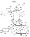
- Figure 1illustrates a braking device of an aircraft wheel set, and it has been illustrated, by way of example, a set of two pairs of wheels R, one of which pair is to the left and the other to the right of the aircraft.
- the brakes rated F on each wheelare actuated from brake pedals not shown here.
- each wheelis here equipped with a T speedometer addressing each an information to the electronic organs of control in relation to the speed of the wheel concerned.
- the braking device rated 100has two pressure sources each supplying a hydraulic circuit.
- a so-called normal hydraulic circuitis thus distinguished 101, and a hydraulic circuit called emergency 102, which intervenes in the event of a breakdown.
- the normal circuit 101is arranged in accordance with a traditional technique, in particular by comprising associated brake servovalves 109 each with a wheel brake. We will therefore only recall briefly the different components of this hydraulic circuit 101.
- the circuit entry marked 103leads to a solenoid valve 104, downstream of which there is a branch 105 equipped with a pressure sensor 106.
- Branch 105leads to a common branch 107 supplying parallel branches 108 in number equal to that of the number of wheels concerned (here four).
- Each branch 108has successively a double-stage hydraulic servovalve of traditional type 109, downstream of which there is a hydraulic fuse 110, and a connection for a pressure 111.
- the backup circuit 102includes a hydraulic source which is here constituted by an accumulator hydraulic.
- This backup circuit 102includes more precisely an inlet 112 leading to a non-return valve 113, downstream of which there is a first branch 114 equipped with an accumulator 115 and a pressure sensor 116, and leading to a solenoid valve 117 which is analogous to the above-mentioned solenoid valve 104.
- the other branch 119leads to her a park solenoid valve 122, downstream of which there is a branch 123 leading to the entrance of two valves shuttles 121, downstream of which there is a fuse hydraulic 124 and a pressure sensor 125, front to arrive by a branch 128 at brake F of each of wheels.
- valves 150which, in accordance with a feature of the invention, are valves with direct drive (or "direct drive valve”, or DDV).
- DDVdirect drive valve
- Each of these direct drive valves 150is electrically controlled by an electronic unit of associated command denoted 120 (here common to the two valves), by means of connections denoted 127.
- each direct drive valve 150is preferably fitted control electronics, internal to said valve, which provides pressure control of the drive valve direct and receives unit pressure commands associated control electronics 120.
- Use output hydraulic of each of these valves 150is noted 126, and leads to the other entry of the aforementioned shuttle valves 121.
- the brake valves of the circuit emergency 102are constituted by valves with drive direct (here two valves 150), while the valves of braking of the normal circuit 101 are servovalves 109 of traditional type.
- Figure 4shows part of the hydraulic circuit brake rated 10, with a supply line 11 arriving on a solenoid valve 12.
- the outlet use of the solenoid valve, noted 13,leads to a valve direct drive 50, the return output of this same solenoid valve 12 being noted 15.
- the use output of the valve 50 with direct driveis noted 14 and leads to the brake (s) concerned, while the return output denoted 16 of said valve joins a line 17 common to the output 15 of return of the solenoid valve 12.
- a electronic control unit 20receives orders pilot-controlled brake systems, such as symbolized by the arrow 18. This electronic unit of command 20 can thus send an opening order to the upstream solenoid valve 12, as symbolized by line 19, as well as a pressure command to the drive valve direct 50 (or more exactly to the control electronics internal to this valve), as symbolized by line 21.
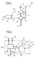
- FIG. 5provides a better understanding of the layout of the aforementioned direct drive valve 50.
- the valve 50is here diagrammed by a rectangle in lines mixed, and essentially includes a distributor hydraulic 30 and an electric actuating motor 31 which is connected to this distributor by a mechanical link 32.
- the mechanical connection 32is shown here so schematic, but we can easily understand that this type of link includes any type of conventional mechanical device able to transform a rotational movement into a linear movement, a rotational movement into another rotational movement, or linear movement in another linear movement, thus acting as appropriate on the sliding drawer or rotating distributor valve hydraulic 30.
- the distributor 30is connected to the power supply high pressure hydraulics 13, at the outlet of use 14, and at the low pressure return output 16 all shown in Figure 4.
- the distributor 30is the only hydraulic stage of the direct drive valve 50, unlike traditional servovalves which include two hydraulic stages.
- the drive valve direct 50also includes control electronics denoted 37, internal to said valve, which receives orders from pressure delivered by the control unit 20 via the line 21 shown in FIG. 4.
- the hydraulic motor actuation 31is thus controlled by the electronics of associated electronic control 37, as shown schematically by the arrow 38.
- valve with drive direct 50is controlled by pressure, the control by pressure provided by the control electronics associated internal.
- the direct drive valve 50thus additionally comprises a pressure sensor 33 stitched on the use pipe 14 of the distributor 30, which sensor sends an electrical signal representative of the pressure measured at control electronics 37, as shown schematically by line 34. So the electrical order sent by control electronics 37 to the electric motor 31 takes into account at all times the operating pressure measured by the pressure sensor 33.
- This pressure sensor 33which consumes little energy, can provide very high accuracy, in the range of bar over the entire range of use (we know that the servovalves show an error of up to about ten bars at certain points on the beach of use).
- the pressure sensor 33may furthermore have an integrated temperature correction device so as to remove any harmful influence or sensitivity to temperature (remember that traditional servovalves are extremely sensitive to temperature, this influence being of the order of a few bars per ten degrees Celsius).
- the direct drive valve 50is also much less sensitive to fluctuations than traditional servovalves with two hydraulic stages, thanks to the pressure produced by the pressure sensor 33. In the case where the pressure sensor 33 is provided, this sensor is downstream of the distributor, which is in favor insensitivity to pressure variations.
- Circuit 200 illustrated in FIG. 2comprises a normal circuit 201, and an emergency circuit 202.
- a pipe supply 203leading to a solenoid valve 204, downstream of which a common branch 205 supplies two pipelines 206 equipped on one hand with a servovalve 207 and on the other hand a pressure sensor 208.
- the orders pilot-controlled braking systemssymbolized by line 209, arrive at an electronic unit of normal circuit 210 command.
- Command commands addressed to the solenoid valve 204 on the one hand and to the servovalves 207 on the other hand,are respectively symbolized by the lines 211 and 212.
- the electronic control unit 210also receives electrical signals from two pressure sensors 208, as shown schematically by the lines 213.
- an electronic control unit for the emergency circuit 220receiving electrical commands from braking controlled by the pilot, as shown schematically by the line 224, and issuing pressure orders to each of the two direct drive valves 250 of the circuit relief.
- the backup circuit 202has an input supply 214 leading to a common branch 215 which feeds two branches 216 and 217.
- Branch 217includes a solenoid valve 219 which receives electrical signals from control of the electronic control unit 220, as shown schematically by line 226. Downstream of the solenoid valve 219, there is a common branch 221 serving two branches 222 each equipped with a direct drive valve 250, then, downstream thereof, a shuttle valve 223.
- the direct drive valves 250receive an order control unit 220, as shown by lines 227.
- Figure 3illustrates another variant of the braking device of the invention, which is fairly close of the one just described with reference to the figure 2.
- the main difference compared to circuit 200 previously describedlies in the replacement, in the normal circuit, traditional type 207 servovalves by direct drive brake valves 351 similar to the valves marked 350 already provided for the emergency circuit 302.
- the circuit 300 of FIG. 3has a normal 301 circuit also fitted with valves direct drive 351.
- the other components illustrated in figure 3correspond exactly to those of circuit 200 illustrated in Figure 2, and the same references are used increased by 100 for homologous components, which will therefore not be described again.
- the brake valves of the normal circuit 301 and emergency circuit 302are therefore all consisting of direct drive valves, 351 and 350 respectively. This results in braking electric taking full advantage of the replacement of traditional two-stage hydraulic servovalves by direct drive valves as above described.
- a second servo loopto have additional control, like illustrated in FIG. 5: in fact, a servo-control is produced internal in position, thanks to a position sensor 35 associated with the electric actuating motor 31, which sends an electrical signal corresponding to the electronics associated command 37, as shown by line 36, this additional control loop being represented in mixed lines to better show his optional character.
- this second position control loopdoes not not from the electric motor 31, but from the distributor 30, to send a corresponding electrical signal to the control electronics 37.
- the additional control means obtained through this second servo loopfurther improves accuracy and dynamic response.
- direct drive valveshaving no first hydraulic stage unlike traditional servovalves (for example of the potentiometer type hydraulic quadruple), the power to control the valve distributor is electric (this is the motor control) and no longer hydraulic (leakage from first floor).
- the very low leakage from the drive valve directlimited to the distributor thereof, considerably facilitates the choice of a braking mode electric on a supply circuit limited in volume (for example constituted by a hydraulic accumulator).
Landscapes
- Engineering & Computer Science (AREA)
- Mechanical Engineering (AREA)
- Transportation (AREA)
- Aviation & Aerospace Engineering (AREA)
- Regulating Braking Force (AREA)
- Valves And Accessory Devices For Braking Systems (AREA)
- Braking Systems And Boosters (AREA)
Abstract
Description
Translated fromFrenchLa présente invention concerne le freinagecontrôlé d'un train de roues d'aéronef, et plus particulièrementun dispositif de freinage d'un train de roues dontles roues sont en général réparties en deux groupes agencéssymétriquement de part et d'autre d'un plan longitudinalmédian de l'aéronef, du type dans lequel chaque roue estéquipée d'un frein actionné à partir de pédales de frein.The present invention relates to brakingcontrolled from an aircraft wheel train, and more particularlya braking device of a wheel set includingthe wheels are generally divided into two groups arrangedsymmetrically on either side of a longitudinal planemedian of the aircraft, of the type in which each wheel isequipped with a brake actuated from brake pedals.
Il existe déjà de nombreux dispositifs de freinagequi sont équipés d'un premier circuit hydrauliquealimenté par une source hydraulique associée et utilisépour le freinage lorsque les conditions sont normales, etd'un circuit hydraulique de secours alimenté par une autresource de pression hydraulique, intervenant seulement encas de panne.There are already many braking deviceswhich are equipped with a first hydraulic circuitpowered by an associated hydraulic source and usedfor braking when conditions are normal, andan emergency hydraulic circuit powered by anotherhydraulic pressure source, intervening only infailure.
Traditionnellement, les deux circuits hydrauliques(normal et secours) mènent à chacun des différentsfreins via une valve de freinage qui est une servovalvecommandée électriquement par une unité de pilotage quimesure des informations correspondant à l'enfoncement despédales de freins et en général aussi à la vitesse de laroue concernée. Pour l'état de la technique, on pourra seréférer aux documents EP-A-0 443 213, US-A-4,834,465, US-A-5,050,940,US-A-5,024,491, US-A-3,926,479, FR-A-2.038.801,et DE-B-1.118.020. Un autre exemple de dispositif defreinage électro-hydraulique d'un train de roues d'aéronefparticulièrement élaboré est décrit dans le document US-A-5,397,173de la demanderesse.Traditionally, the two hydraulic circuits(normal and emergency) lead to each of the differentbrakes via a brake valve which is a servovalveelectrically controlled by a control unit whichmeasures information corresponding to the sinking ofbrake pedals and in general also at the speed of thewheel concerned. For the state of the art, we canrefer to documents EP-A-0 443 213, US-A-4,834,465, US-A-5,050,940,US-A-5,024,491, US-A-3,926,479, FR-A-2,038.801,and DE-B-1,118,020. Another example of aelectro-hydraulic braking of an aircraft wheel setparticularly elaborate is described in document US-A-5,397,173of the plaintiff.
Les différents dispositifs de freinage décritsdans les documents précités comportent ainsi des servovalvesà commande électrique, dont la structure comportesystématiquement deux étages hydrauliques reliés entre euxpar une liaison hydraulique et respectivement associés à lacommande et à la distribution, l'étage de commande agissantsur le tiroir de l'étage de distribution. L'étage hydrauliquede commande est commandé électriquement, et la pression d'alimentation en entrée de la servovalve est modulée auniveau de l'étage de distribution par des sections depassage (gicleurs) fonctionnant sur un principe de fuitehydraulique en général de l'ordre d'un litre par minute.Ces fuites hydrauliques sont toujours nécessaires dans unetelle conception, et leur importance rend difficilel'utilisation de telles servovalves lorsque la sourcehydraulique est constituée par un accumulateur hydraulique,ce qui peut être le cas pour le circuit secours. En effet,le volume de fluide consommé par la fuite permanente de cesservovalves n'est plus disponible pour alimenter lesfreins, ce qui limite considérablement la durée et lenombre d'applications de freinage avant que l'accumulateurne soit vide.The different braking devices describedin the aforementioned documents thus include servovalveselectrically operated, the structure of which comprisessystematically two hydraulic stages interconnectedby a hydraulic connection and respectively associated with thecontrol and distribution, the control stage actingon the drawer of the distribution stage. The hydraulic stagecontrol is electrically controlled, and the pressuresupply valve at the servovalve is modulatedlevel of the distribution stage by sections ofpassage (sprinklers) operating on a leak principlehydraulic in general of the order of one liter per minute.These hydraulic leaks are always necessary in asuch design, and their importance makes it difficultthe use of such servovalves when the sourcehydraulic consists of a hydraulic accumulator,which may be the case for the emergency circuit. Indeed,the volume of fluid consumed by the permanent leakage of theseservovalves is no longer available to supply thebrakes, which considerably limits the duration andnumber of braking applications before the accumulatoris not empty.
Bien que la structure des servovalves de freinageactuellement utilisées soit globalement maítrisée, lesspécialistes connaissent bien les inconvénients et lescontraintes de l'utilisation de tels types de valves defreinage.Although the structure of the brake servo valvescurrently used is generally under control, thespecialists are well aware of the disadvantages andconstraints of using such types of valvesbraking.
La pression d'utilisation récupérée en sortie dela servovalve et qui est fonction de l'intensité du courantde consigne est en effet obtenue avec une précisionmédiocre. Tout d'abord, le réglage mécanique de la servovalveau niveau des gicleurs ne permet pas d'obtenir unedispersion sur la pression d'utilisation inférieure àquelques bars, voire de l'ordre d'une dizaine de bars encertains points, compte tenu des phénomènes de non linéaritéet d'hystérésis propres à tout appareil hydraulique.De plus, la servovalve est sensible aux fluctuations de lapression d'alimentation et de la température du fluidehydraulique, ce qui peut induire des variations de pressiond'utilisation de plusieurs bars, même en utilisationnormale. Enfin, l'usure mécanique des gicleurs induit unedérive inévitable dans le temps.The operating pressure recovered at the outlet ofthe servovalve and which is a function of the intensity of the currentsetpoint is indeed obtained with precisionpoor. First, the mechanical adjustment of the servovalveat the sprinkler level does not allow obtaining adispersion on operating pressure less thana few bars, or even around ten bars incertain points, taking into account the phenomena of non-linearityand hysteresis specific to any hydraulic device.In addition, the servovalve is sensitive to fluctuations in thesupply pressure and fluid temperaturehydraulic, which can induce pressure variationsuse of several bars, even in usenormal. Finally, the mechanical wear of the nozzles induces ainevitable drift over time.
L'invention vise précisément à résoudre ce problème, et à concevoir un dispositif de freinage plusperformant, en étant moins sensible aux phénomènes detempérature et d'usure, et aux fluctuations d'alimentation,tout en restant très précis pour la pression d'utilisationsans qu'il soit nécessaire d'effectuer des ajustementspériodiques contraignants.The invention aims precisely to solve thisproblem, and to design a more braking deviceefficient, being less sensitive to the phenomena oftemperature and wear, and to supply fluctuations,while remaining very precise for the operating pressurewithout the need to make adjustmentsbinding periodicals.
L'invention a ainsi pour objet de réaliser undispositif de freinage d'un train de roues d'aéronef dontla structure permet d'obtenir un freinage précis etconstant dans le temps, sans les inconvénients précitésinhérents à l'utilisation de servovalves de freinage à deuxétages hydrauliques.The object of the invention is therefore to produce abraking device of an aircraft wheel set includingthe structure provides precise braking andconstant over time, without the aforementioned drawbacksinherent in the use of two-way brake servo valveshydraulic stages.
Ce problème est résolu conformément à l'inventiongrâce à un dispositif de freinage d'un train de rouesd'aéronef, dont chaque roue est équipée d'un frein actionnéà partir de pédales de freinage, ledit dispositif defreinage comportant deux sources de pression alimentantchacune un circuit hydraulique, dont un circuit normal etun circuit secours intervenant en cas de panne, ces deuxcircuits hydrauliques menant à chacun des différents freinsvia une valve de freinage associée, les valves de freinagedu circuit normal et/ou du circuit secours étant constituéespar des valves à entraínement direct commandéesélectriquement par une unité électronique de commandeassociée.This problem is solved in accordance with the inventionthanks to a wheel train braking deviceaircraft, each wheel of which is fitted with an actuated brakefrom brake pedals, saidbraking with two pressure sources supplyingeach a hydraulic circuit, including a normal circuit andan emergency circuit intervening in the event of a breakdown, these twohydraulic circuits leading to each of the different brakesvia an associated brake valve, the brake valvesof the normal circuit and / or the backup circuit being constitutedby direct drive valves controlledelectrically by an electronic control unitassociated.
Les valves à entraínement direct, ou "directdrive valve" (DDV) pour les anglo-saxons sont, de façonsurprenante pour l'homme de métier, très performantes dansle cadre d'une utilisation intégrée à des systèmes defreinage d'aéronef. De telles valves à entraínement directont jusque là été seulement utilisées dans des machinesoutilspour des contrôles de position ou de déplacement(par exemple dans des laminoirs), ou dans des suspensionsde véhicules automobiles. Dans les utilisations connues detelles valves à entraínement direct, il était en général prévu un asservissement en débit (et non en pression),selon lequel la position du distributeur de la valve estcontrôlée par un capteur de position.Direct drive, or "direct" valvesdrive valve "(DDV) for Anglo-Saxons are, sosurprising for the skilled person, very efficient inas part of an integrated use withaircraft braking. Such direct drive valveshave so far only been used in machine toolsfor position or displacement controls(for example in rolling mills), or in suspensionsof motor vehicles. In the known uses ofsuch direct drive valves it was generallyprovided for flow control (not pressure),that the position of the valve distributor iscontrolled by a position sensor.
Conformément à un premier mode d'exécution dudispositif de freinage de l'invention, les valves defreinage du circuit secours sont seules constituées par desvalves à entraínement direct, les valves de freinage ducircuit normal étant quant à elles des servovalves de typetraditionnel. On obtient déjà un avantage considérablerésultant de la difficulté à utiliser les servovalvesclassiques à double étage hydraulique dans le circuitsecours, dans le cas où la source hydraulique de ce circuitest constituée par un accumulateur hydraulique. On pourraalors prévoir que les valves de freinage à entraínementdirect sont chacune associées aux freins d'une paire deroues.In accordance with a first embodiment of thebraking device of the invention, the valvesbraking of the emergency circuit are only constituted bydirect drive valves, the brake valves of thenormal circuit being servovalves of the typetraditional. There is already a considerable advantageresulting from the difficulty in using the servovalvesclassic double hydraulic stages in the circuitbackup, in the event that the hydraulic source of this circuitconsists of a hydraulic accumulator. We will be able tothen provide that the brake valves to drivedirect are each associated with the brakes of a pair ofwheels.
Conformément à une variante d'exécution, lesvalves de freinage du circuit normal et du circuit secourssont toutes constituées par des valves à entraínementdirect. On dispose alors des nombreux avantages qui serontdétaillés plus loin, inhérents à l'utilisation de valves àentraínement direct pour l'ensemble du circuit de freinage,donc à la fois pour une utilisation normale et une utilisationen cas de panne.In accordance with an alternative embodiment, thebrake valves of the normal circuit and the emergency circuitare all formed by drive valvesdirect. We then have many advantages which will bedetailed later, inherent in the use ofdirect drive for the entire braking circuit,so both for normal use and usein case of failure.
Conformément à une caractéristique avantageuse,certaines au moins des valves à entraínement direct sontasservies en pression.According to an advantageous characteristic,at least some of the direct drive valves arepressure controlled.
Un tel asservissement en pression est extrêmementintéressant, dans le cadre de l'utilisation de valves defreinage à entraínement direct dans un circuit de freinage,contrairement à l'asservissement en position parfoisutilisé pour de telles valves dans des environnementstechnologiques complètement différents.Such pressure control is extremelyinteresting, in the context of the use ofdirect drive braking in a braking circuit,unlike the servo in position sometimesused for such valves in environmentscompletely different technology.
De préférence alors, chaque valve à entraínementdirect asservie en pression inclut un distributeur hydraulique et un moteur électrique d'actionnement commandé parune électronique de commande associée, et, sur la sortied'utilisation du distributeur hydraulique, un capteur depression qui envoie à ladite électronique de commande unsignal électrique représentatif de la pression mesurée. Sicela est souhaitable, la valve à entraínement directasservie en pression pourra être également asservie enposition grâce à un capteur de position associé au moteurélectrique d'actionnement, qui envoie un signal électriquecorrespondant à l'électronique de commande associée.Preferably then, each drive valvedirect pressure controlled includes a hydraulic distributorand an electric actuation motor controlled byassociated control electronics, and on the outputuse of the hydraulic distributor, apressure which sends said control electronics aelectrical signal representative of the pressure measured. Yesthis is desirable, the direct drive valvepressure-controlled can also be controlled byposition thanks to a position sensor associated with the motorelectrical actuation, which sends an electrical signalcorresponding to the associated control electronics.
La valve à entraínement direct, ne comportant pasle premier étage hydraulique des servovalves traditionnelles(par exemple un potentiomètre hydraulique quadruple),la puissance pour commander le distributeur de la valve estmaintenant électrique (il ne s'agit en effet que de lacommande du moteur d'actionnement du distributeur) et nonplus hydraulique (par la fuite du premier étage hydrauliquede la servovalve). De plus, contrairement à ce que l'onrencontrait avec les servovalves traditionnelles asserviesou non en pression, la fuite de la valve à entraínementdirect (alimentation vers retour) est maintenant circonscriteau distributeur de cette valve, et donc par constructioninférieure à la fuite d'une servovalve traditionnelle.Ceci ouvre la voie à un véritable freinage électrique, enparticulier sur le circuit secours où l'alimentation estlimitée en volume, par exemple par l'utilisation d'unaccumulateur hydraulique, ce qui était jusque-là tropcontraignant avec les servovalves traditionnelles du faitde la nécessité d'accroítre de façon considérable le volumehydraulique disponible en alimentation, en particulier enaugmentant la capacité de l'accumulateur hydraulique.The valve with direct drive, not comprisingthe first hydraulic stage of traditional servovalves(for example a quadruple hydraulic potentiometer),the power to control the valve distributor isnow electric (it is indeed only thedistributor actuator motor control) and notmore hydraulic (by the leakage of the first hydraulic stageservovalve). In addition, contrary to what wemet with traditional servo valvesor not under pressure, the leakage of the drive valvedirect (feed to return) is now circumscribedto the distributor of this valve, and therefore by constructionlower than the leakage of a traditional servovalve.This opens the way to real electric braking,particularly on the emergency circuit where the supply islimited in volume, for example by the use of ahydraulic accumulator, which was previously too muchconstraining with traditional servovalves due to the factthe need to dramatically increase the volumehydraulics available in supply, in particular inincreasing the capacity of the hydraulic accumulator.
Conformément à une autre caractéristique intéressante,un circuit de freinage parc est combiné au circuitsecours avec une alimentation commune, ledit circuit defreinage parc menant à chacun des freins de roues par un clapet navette associé disposé en aval de la valve àentraínement direct correspondante.According to another interesting feature,a parking brake circuit is combined with the circuitbackup with a common power supply, said circuitbraking park leading to each of the wheel brakes by aassociated shuttle valve located downstream of thecorresponding direct training.
D'autres caractéristiques et avantages de l'inventionapparaítront plus clairement à la lumière de ladescription qui va suivre et des dessins annexés, concernantdes modes de réalisation particuliers de l'invention,en référence aux figures où :
- la figure 1 est un schéma d'un premier moded'exécution du dispositif de freinage selon l'invention,dans lequel les valves à entraínement direct ne concernentque le circuit secours
- la figure 2 illustre un schéma analogue àcelui de la figure 1, faisant apparaítre l'unité decommande du circuit normal :
- la figure 3 illustre une variante de la figure2, dans laquelle les valves de freinage du circuit normalsont également des valves à entraínement direct :
- la figure 4 est une vue schématique isoléeillustrant l'intégration d'une valve à entraínement directdans un circuit de freinage de type électrique :
- la figure 5 est également une vue schématiquepartielle illustrant une valve à entraínement direct avecson moteur électrique et son distributeur hydraulique,ainsi que ses organes de commande et d'asservissement.
- Figure 1 is a diagram of a first embodiment of the braking device according to the invention, in which the direct drive valves relate only to the emergency circuit
- FIG. 2 illustrates a diagram similar to that of FIG. 1, showing the control unit of the normal circuit:
- FIG. 3 illustrates a variant of FIG. 2, in which the brake valves of the normal circuit are also direct drive valves:
- FIG. 4 is an isolated schematic view illustrating the integration of a direct drive valve in an electric type braking circuit:
- Figure 5 is also a partial schematic view illustrating a direct drive valve with its electric motor and its hydraulic distributor, as well as its control and servo members.
La figure 1 illustre un dispositif de freinaged'un train de roues d'aéronef, et l'on a illustré, à titred'exemple, un ensemble de deux paires de roues R, dont unepaire est à gauche et l'autre à droite de l'aéronef. Lesfreins notés F de chaque roue sont actionnés à partir depédales de freinage non représentées ici. On notera quechaque roue est ici équipée d'un tachymètre T adressantchacun une information aux organes électroniques decommande en rapport avec la vitesse de la roue concernée.Figure 1 illustrates a braking deviceof an aircraft wheel set, and it has been illustrated, by way ofexample, a set of two pairs of wheels R, one of whichpair is to the left and the other to the right of the aircraft. Thebrakes rated F on each wheel are actuated frombrake pedals not shown here. Note thateach wheel is here equipped with a T speedometer addressingeach an information to the electronic organs ofcontrol in relation to the speed of the wheel concerned.
Le dispositif de freinage noté 100 comporte deuxsources de pression alimentant chacune un circuit hydraulique. On distingue ainsi un circuit hydraulique dit normal101, et un circuit hydraulique dit secours 102, quiintervient en cas de panne.The braking device rated 100 has twopressure sources each supplying a hydraulic circuit.A so-called normal hydraulic circuit is thus distinguished101, and a hydraulic circuit called
En l'espèce, le circuit normal 101 est agencéconformément à une technique traditionnelle, notamment encomportant des servovalves de freinage notées 109 associéeschacune à un frein de roue. On rappellera donc seulementbrièvement les différents composants de ce circuit hydraulique101.In this case, the
L'entrée du circuit notée 103 mène à une électrovanne104, en aval de laquelle on trouve une branche 105équipée d'un capteur de pression 106. La branche 105 mèneà une branche commune 107 alimentant en parallèle desbranches 108 en nombre égal à celui du nombre de rouesconcernées (ici quatre). Chaque branche 108 comportesuccessivement une servovalve à double étage hydraulique detype traditionnel 109, en aval de laquelle on trouve unfusible hydraulique 110, et un piquage pour un capteur depression 111.The circuit entry marked 103 leads to a
Le circuit secours 102 comporte quant à lui unesource hydraulique qui est ici constituée par un accumulateurhydraulique. Ce circuit secours 102 comprend plusprécisément une entrée 112 menant à un clapet anti-retour113, en aval duquel on trouve une première branche 114équipée d'un accumulateur 115 et d'un capteur de pression116, et menant à une électrovanne 117 qui est analogue àl'électrovanne 104 précitée. L'autre branche 119 mène quantà elle à une électrovanne de parc 122, en aval de laquelleon trouve une branche 123 menant à l'entrée de deux clapetsnavettes 121, en aval desquels on trouve un fusiblehydraulique 124 et un capteur de pression 125, avantd'arriver par une branche 128 au frein F de chacune desroues.The
En sortie de l'électrovanne 117, on trouve unebranche 118 menant à deux valves 150 qui, conformément à une caractéristique de l'invention, sont des valves àentraínement direct (ou "direct drive valve", ou DDV).Chacune de ces valves 150 à entraínement direct estcommandée électriquement par une unité électronique decommande associée notée 120 (ici commune aux deux valves),au moyen de liaisons notées 127. Ainsi qu'on l'exposeraplus loin plus en détail en référence à la figure 5, chaquevalve à entraínement direct 150 est de préférence équipéed'une électronique de commande, interne à ladite valve, quiassure l'asservissement en pression de la valve à entraínementdirect et reçoit les ordres de pression de l'unitéélectronique de commande associée 120. La sortie d'utilisationhydraulique de chacune de ces valves 150 est notée126, et mène à l'autre entrée des clapets navettes précités121.At the outlet of the
Ainsi, dans le cas du mode de réalisation illustrésur la figure 1, les valves de freinage du circuitsecours 102 sont constituées par des valves à entraínementdirect (ici deux valves 150), tandis que les valves defreinage du circuit normal 101 sont des servovalves 109 detype traditionnel.Thus, in the case of the illustrated embodimentin figure 1, the brake valves of the
Outre la simplification du circuit secours 102qui découle de l'utilisation de valves à entraínementdirect à la place des servovalves traditionnelles, onobtient de nombreux avantages pratiques inhérents à lastructure de ce type particulier de valves, et qui serontmieux compris à la lumière de la description générale quiva suivre des figures schématiques 4 et 5.In addition to the simplification of the
La figure 4 montre une partie de circuit hydrauliquede freinage notée 10, avec une canalisation d'alimentation11 arrivant sur une électrovanne 12. La sortied'utilisation de l'électrovanne, notée 13, mène à une valveà entraínement direct 50, la sortie retour de cette mêmeélectrovanne 12 étant notée 15. La sortie d'utilisation dela vanne 50 à entraínement direct est noté 14 et mène vers le ou les freins concernés, tandis que la sortie retournotée 16 de ladite vanne rejoint une canalisation 17commune à la sortie 15 de retour de l'électrovanne 12. Uneunité électronique de commande 20 reçoit des ordresélectriques de freinage commandés par le pilote, commesymbolisé par la flèche 18. Cette unité électronique decommande 20 peut ainsi envoyer un ordre d'ouverture àl'électrovanne amont 12, comme symbolisé par la ligne 19,ainsi qu'un ordre de pression à la valve à entraínementdirect 50 (ou plus exactement à l'électronique de commandeinterne à cette valve), comme symbolisé par la ligne 21.Figure 4 shows part of the hydraulic circuitbrake rated 10, with a
La figure 5 permet de mieux comprendre l'agencementde la valve à entraínement direct 50 précitée. Lavalve 50 est ici schématisée par un rectangle en traitsmixtes, et comporte essentiellement un distributeurhydraulique 30 et un moteur électrique d'actionnement 31qui est relié à ce distributeur par une liaison mécanique32. La liaison mécanique 32 est représentée ici de façonschématique, mais l'on comprendra aisément que ce type deliaison englobe tout type de dispositif mécanique classiquecapable de transformer un mouvement de rotation en unmouvement linéaire, un mouvement de rotation en un autremouvement de rotation, ou un mouvement linéaire en un autremouvement linéaire, en agissant ainsi selon le cas sur letiroir coulissant ou le boisseau tournant du distributeurhydraulique 30. Le distributeur 30 est relié à l'alimentationhydraulique haute pression 13, à la sortie d'utilisation14, et à la sortie retour basse pression 16 toutesreprésentées en figure 4. Le distributeur 30 est l'uniqueétage hydraulique de la valve à entraínement direct 50,contrairement aux servovalves traditionnelles qui comportentdeux étages hydrauliques. La valve à entraínementdirect 50 comporte également une électronique de commandenotée 37, interne à ladite valve, qui reçoit les ordres depression délivrés par l'unité de commande 20 via la ligne 21 représentée sur la figure 4. Le moteur hydrauliqued'actionnement 31 est ainsi commandé par l'électronique decommande électronique associée 37, comme schématisé par laflèche 38.Figure 5 provides a better understanding of the layoutof the aforementioned
Bien que cela ne soit pas obligatoire, il est enoutre intéressant de prévoir que la valve à entraínementdirect 50 soit asservie en pression, l'asservissement enpression étant assuré par l'électronique de commandeinterne associée.Although it is not mandatory, it isin addition interesting to envisage that the valve with drivedirect 50 is controlled by pressure, the control bypressure provided by the control electronicsassociated internal.
En l'espèce, la valve à entraínement direct 50comporte ainsi en plus un capteur de pression 33 piqué surla canalisation d'utilisation 14 du distributeur 30, lequelcapteur envoie un signal électrique représentatif de lapression mesurée à l'électronique de commande 37, commeschématisé par la ligne 34. Ainsi, l'ordre électriqueenvoyé par l'électronique de commande 37 au moteur électriqued'actionnement 31 tient compte à tout moment de lapression d'utilisation mesurée par le capteur de pression33. Ce capteur de pression 33, qui consomme peu d'énergie,peut procurer une précision très élevée, de l'ordre du barsur toute la plage d'utilisation (on sait que les servovalvestraditionnelles présentent une erreur pouvant atteindreune dizaine de bars environ en certains points de la plaged'utilisation). Le capteur de pression 33 pourra en outrecomporter un organe intégré de correction de température defaçon à supprimer toute influence néfaste ou sensibilité àla température (on se rappelle que les servovalves traditionnellessont extrêmement sensibles à la température,cette influence étant de l'ordre de quelques bars pardizaine de degrés Celsius). La valve à entraínement direct50 est en outre beaucoup moins sensible aux fluctuationsd'alimentation que ne le sont les servovalves traditionnellesà deux étages hydrauliques, grâce à l'asservissement enpression réalisé par le biais du capteur de pression 33.Dans le cas où le capteur de pression 33 est prévu, ce capteur est en aval du distributeur, ce qui est en faveurde l'insensibilité aux variations de pression.In this case, the
L'homme de l'art comprendra que l'asservissementen pression de la valve à entraínement direct n'est pasindispensable pour une telle valve, celle-ci pouvant eneffet fonctionner avec un capteur de position en moded'asservissement en débit, mais ceci imposerait alors derajouter une boucle d'asservissement en pression à l'extérieurde la valve à entraínement direct, car le contrôle dufreinage impose un contrôle de la pression dans les freins.C'est pourquoi il sera en général préféré un asservissementinterne en pression comme cela vient d'être décrit.Those skilled in the art will understand that enslavementpressure of the direct drive valve is notessential for such a valve, which caneffect operate with a position sensor in modespeed control, but this would requireadd a pressure control loop outsideof the direct drive valve, because the control of thebraking requires checking the brake pressure.This is why it will generally be preferred a subjugationinternal pressure as just described.
Ainsi, avec la valve à entraínement direct 50, onne trouve plus les phénomènes d'usure qui étaient inhérentsà la présence de gicleurs dans les servovalves traditionnelles,de sorte qu'il n'y a plus de problèmes de dérivedans le temps. De plus, on pourra en général, grâce à cetype de valve à entraínement direct, se passer des ajustementspériodiques qui étaient obligatoires avec lesservovalves traditionnelles, une simple vérificationpériodique par le calculateur étant maintenant suffisante.Thus, with the
On a vu sur la figure 1 qu'il était très intéressantd'utiliser des valves à entraínement direct 150 pourle circuit secours 102. Ceci est particulièrement importantsi l'on se rappelle qu'avec les servovalves traditionnelleson était lié au principe d'une fuite hydraulique permanenteet nécessaire, ce qui n'est plus le cas avec des valves àentraínement direct. Il y a bien entendu quelques fuites auniveau du tiroir ou du boisseau de chaque valve à entraínementdirect, mais ces fuites sont comparativement trèsfaibles par rapport aux fuites de 0,5 à 1 litre par minutecouramment rencontrées avec les servovalves traditionnelles,les fuites au niveau du tiroir ou du boisseau représentantmaintenant environ un dixième des fuites retourrencontrées avec une servovalve classique.We saw in Figure 1 that it was very interestingto use
On va maintenant décrire, en se référant à lafigure 2, un dispositif de freinage analogue à celui de lafigure 1, avec l'unité de commande associée au circuitnormal de ce dispositif de freinage. Le circuit 200illustré sur la figure 2 comporte un circuit normal 201, etun circuit secours 202.We will now describe, with reference to theFigure 2, a braking device similar to that of theFigure 1, with the control unit associated with the circuitnormal of this braking device.
Pour le circuit normal 201, on trouve une canalisationd'alimentation 203, menant à une électrovanne 204,en aval de laquelle une branche commune 205 alimente deuxcanalisations 206 équipées d'une part d'une servovalve 207et d'autre part d'un capteur de pression 208. Les ordresélectriques de freinage commandés par le pilote, symboliséspar la ligne 209, arrivent à une unité électronique decommande du circuit normal 210. Les ordres de commandeadressés à l'électrovanne 204 d'une part et aux servovalves207 d'autre part, sont respectivement symbolisés par leslignes 211 et 212. L'unité électronique de commande 210reçoit par ailleurs les signaux électriques provenant desdeux capteurs de pression 208, comme schématisé par leslignes 213.For the
Pour le circuit secours 202, on retrouve, commeà la figure 4, une unité électronique de commande ducircuit secours 220, recevant des ordres électriques defreinage commandés par le pilote, comme schématisé par laligne 224, et délivrant les ordres de pression à chacunedes deux valves à entraínement direct 250 du circuitsecours.For the
Le circuit secours 202 comporte une entréed'alimentation 214 menant à une branche commune 215 quialimente deux branches 216 et 217. La branche 217 inclutune électrovanne 219 qui reçoit des signaux électriques decommande de l'unité de commande électronique 220, commeschématisé par la ligne 226. En aval de l'électrovanne 219,on trouve une branche commune 221 desservant deux branches222 équipées chacune d'une valve à entraínement direct 250, puis, en aval de celle-ci, d'un clapet navette 223. Lesvalves à entraínement direct 250 reçoivent un ordreélectrique de l'unité de commande 220, comme schématisé parles lignes 227.The
La présence des unités électroniques de commande210 (pour le circuit normal) et 220 (pour le circuitsecours) montrent là encore que l'on utilise ainsi unfreinage électrique.The presence of electronic control units210 (for the normal circuit) and 220 (for the circuitagain) again show that we are using aelectric braking.
Ceci est encore plus vrai dans la mesure où,comme cela est illustré sur la figure 2, on peut intégreraussi un circuit de freinage parc au circuit secours 202,la commande du freinage parc se manifestant sous la formed'ordres électriques de freinage commandés par le pilote.On distingue ainsi, en aval de la branche commune 215précitée du circuit 202, une deuxième branche latérale 216menant à un distributeur de freinage parc 218, en avalduquel la canalisation se dédouble pour se raccorder auxclapets navettes précités 223. Le distributeur 218 reçoitun ordre électrique de freinage parc commandé par lepilote, comme schématisé par la ligne 225. Grâce aux deuxclapets navettes 223, il est facile d'obtenir le mode defreinage désiré, qu'il s'agisse d'un freinage parc ensituation normale, ou d'un freinage secours en cas depanne.This is even more true since,as illustrated in figure 2, we can integratealso a braking circuit applied to the
La figure 3 illustre une autre variante dudispositif de freinage de l'invention, qui est assez prochede celle qui vient d'être décrite en référence à la figure2. La principale différence par rapport au circuit 200précédemment décrit réside dans le remplacement, dans lecircuit normal, des servovalves 207 de type traditionnelpar des valves de freinage à entraínement direct 351analogues aux valves notées 350 déjà prévues pour lecircuit secours 302. Ainsi, le circuit 300 de la figure 3comporte un circuit normal 301 également équipé de valvesà entraínement direct 351. Les autres organes illustrés en figure 3 correspondent exactement à ceux du circuit 200illustré en figure 2, et l'on a repris les mêmes référencesaugmentées de 100 pour les composants homologues, lesquelsne seront donc pas à nouveau décrits.Figure 3 illustrates another variant of thebraking device of the invention, which is fairly closeof the one just described with reference to the figure2. The main difference compared to
Sur la figure 3, les valves de freinage ducircuit normal 301 et du circuit secours 302 sont donctoutes constituées par des valves à entraínement direct,respectivement 351 et 350. On obtient ainsi un freinageélectrique profitant pleinement du remplacement desservovalves traditionnelles à deux étages hydrauliques pardes valves à entraínement direct telles que précédemmentdécrites.In Figure 3, the brake valves of the
Bien que cela ne soit pas illustré, on pourraitprévoir une autre variante dans laquelle le circuit normalserait seul équipé de valves à entraínement direct, tandisque le circuit secours serait réalisé de façon traditionnelle.Néanmoins, on profiterait alors beaucoup moins desavantages précités conférés par l'utilisation des valves àentraínement direct.Although not shown, we couldprovide another variant in which the normal circuitwould be alone equipped with direct drive valves, whilethat the emergency circuit would be carried out in the traditional way.Nevertheless, we would then benefit much less fromaforementioned advantages conferred by the use ofdirect training.
Pour chacune des valves à entraínement direct150, 250, 350 et 351, précédemment mentionnées, il seraavantageux de prévoir un asservissement en pression interneà la valve à entraínement direct, comme cela a été déjàdécrit plus en détail pour la valve à entraínement direct50 en référence à la figure 5.For each of the
On pourra de même prévoir pour chacune de cesvalves à entraínement direct, une deuxième boucle d'asservissementpour avoir un contrôle supplémentaire, commeillustré sur la figure 5 : on réalise en effet un asservissementinterne en position, grâce à un capteur de position35 associé au moteur électrique d'actionnement 31, quienvoie un signal électrique correspondant à l'électroniquede commande associée 37, comme schématisé par la ligne 36,cette boucle supplémentaire d'asservissement étant représentéeen traits mixtes pour mieux faire apparaítre son caractère optionnel. En variante, on pourrait prévoir quecette deuxième boucle d'asservissement en position neprovienne pas du moteur électrique 31, mais du distributeur30, pour envoyer un signal électrique correspondant versl'électronique de commande 37. Le moyen de contrôle supplémentaireobtenu grâce à cette deuxième boucle d'asservissementaméliore encore la précision et la réponse dynamique.We can also provide for each of thesedirect drive valves, a second servo loopto have additional control, likeillustrated in FIG. 5: in fact, a servo-control is producedinternal in position, thanks to a
On est ainsi parvenu à réaliser un dispositif defreinage, à mode de commande électrique, qui, grâce à laprésence, sur au moins une partie de son circuit hydraulique,de valves à entraínement direct, procure un grandnombre d'avantages techniques qui seront simplementrappelés ci-après pour montrer la supériorité d'une telleutilisation par rapport à l'utilisation traditionnelle deservovalves dans les circuits hydrauliques de freinaged'aéronefs.We thus managed to achieve a device forbraking, electrically controlled, which, thanks to thepresence, on at least part of its hydraulic circuit,direct drive valves, provides greatnumber of technical advantages which will simply berecalled below to show the superiority of suchuse compared to traditional use ofservovalves in hydraulic brake circuitsaircraft.
On obtient maintenant une meilleure précision etune absence de dérive dans le temps. On obtient égalementune faible sensibilité aux fluctuations de température etde pression d'alimentation. On évite enfin la nécessitéd'effectuer des ajustements hydrauliques de la caractéristiquestatique de la valve, ce qui n'était bien entendupas le cas avec les servovalves traditionnelles à doubleétage hydraulique.Now we get better accuracy andan absence of drift over time. We also getlow sensitivity to temperature fluctuations andsupply pressure. We finally avoid the needmake hydraulic adjustments to the characteristicstatic valve, which was of coursenot the case with traditional double servovalveshydraulic stage.
En outre, les valves à entraínement directn'ayant pas de premier étage hydraulique contrairement auxservovalves traditionnelles (par exemple du type à potentiomètrehydraulique quadruple), la puissance pour commanderle distributeur de la valve est électrique (c'est lacommande du moteur) et non plus hydraulique (fuite dupremier étage). La très faible fuite de la valve à entraínementdirect, circonscrite au distributeur de celle-ci,facilite considérablement le choix d'un mode de freinageélectrique sur un circuit d'alimentation limité en volume(par exemple constitué par un accumulateur hydraulique).In addition, direct drive valveshaving no first hydraulic stage unliketraditional servovalves (for example of the potentiometer typehydraulic quadruple), the power to controlthe valve distributor is electric (this is themotor control) and no longer hydraulic (leakage fromfirst floor). The very low leakage from the drive valvedirect, limited to the distributor thereof,considerably facilitates the choice of a braking modeelectric on a supply circuit limited in volume(for example constituted by a hydraulic accumulator).
L'invention n'est pas limitée aux modes d'utilisationqui viennent d'être décrits, mais englobe aucontraire toute variante reprenant, avec des moyenséquivalents, les caractéristiques essentielles énoncéesplus haut.The invention is not limited to the modes of usewhich have just been described, but includes aton the contrary any variant taking over, with meansequivalent, the essential characteristics statedupper.
Claims (8)
Translated fromFrenchApplications Claiming Priority (2)
| Application Number | Priority Date | Filing Date | Title |
|---|---|---|---|
| FR9800197AFR2773530B1 (en) | 1998-01-12 | 1998-01-12 | DEVICE FOR BRAKING AN AIRCRAFT WHEEL TRAIN |
| FR9800197 | 1998-01-12 |
Publications (2)
| Publication Number | Publication Date |
|---|---|
| EP0928740A1true EP0928740A1 (en) | 1999-07-14 |
| EP0928740B1 EP0928740B1 (en) | 2004-09-01 |
Family
ID=9521656
Family Applications (1)
| Application Number | Title | Priority Date | Filing Date |
|---|---|---|---|
| EP98403330AExpired - LifetimeEP0928740B1 (en) | 1998-01-12 | 1998-12-30 | Brake device for a set of aircraft wheels |
Country Status (7)
| Country | Link |
|---|---|
| US (1) | US6193326B1 (en) |
| EP (1) | EP0928740B1 (en) |
| JP (1) | JP4260959B2 (en) |
| CA (1) | CA2259106C (en) |
| DE (1) | DE69825963T2 (en) |
| ES (1) | ES2227789T3 (en) |
| FR (1) | FR2773530B1 (en) |
Cited By (7)
| Publication number | Priority date | Publication date | Assignee | Title |
|---|---|---|---|---|
| US6193326B1 (en)* | 1998-01-12 | 2001-02-27 | Messier-Bugatti | Apparatus for braking a set of aircraft wheels |
| EP0980807A3 (en)* | 1998-08-15 | 2003-03-19 | Dunlop Aerospace Limited | Braking system |
| FR2915157A1 (en)* | 2007-04-18 | 2008-10-24 | Beringer Sa Sa | SAFETY BRAKING DEVICE MOUNTED BETWEEN A HYDRAULIC FLUID RESERVOIR AND ACTUATOR DEVICES SUITABLE FOR ACTING ON BRAKING ELEMENTS. |
| FR2955817A1 (en)* | 2010-02-03 | 2011-08-05 | Messier Bugatti | HYDRAULIC BRAKE ARCHITECTURE FOR AIRCRAFT WITH HALF-CAVITY BRAKES |
| CN102328750A (en)* | 2010-06-10 | 2012-01-25 | 梅西耶-布加蒂公司 | Be fitted with the aircraft of individual drive device |
| EP3418135A1 (en)* | 2017-06-21 | 2018-12-26 | Airbus Operations Limited | Controlling vehicle brakes |
| FR3153596A1 (en)* | 2023-09-28 | 2025-04-04 | Safran Landing Systems | Simplified aircraft braking system |
Families Citing this family (20)
| Publication number | Priority date | Publication date | Assignee | Title |
|---|---|---|---|---|
| US6390571B1 (en)* | 2000-06-29 | 2002-05-21 | Goodrich Corporation | Redundant aircraft braking system architecture |
| FR2816583B1 (en)* | 2000-11-10 | 2003-02-21 | Messier Bugatti | ARCHITECTURE OF AN AIRCRAFT HYDRAULIC BRAKING SYSTEM |
| US6672688B2 (en) | 2001-05-22 | 2004-01-06 | Honeywell International Inc. | Anti-lock braking system module for aircraft equipped with master cylinder brake systems |
| US6826909B2 (en)* | 2001-11-08 | 2004-12-07 | Parker-Hannifin Corp. | Hydraulic gerotor motor with integral shuttle valve |
| DE10222123A1 (en)* | 2002-05-17 | 2003-11-27 | Aircabin Gmbh | Aircraft luggage locker has gas spring offload unit locked closed by handle sensor controlled electrically actuated valve |
| AT412916B (en)* | 2002-07-19 | 2005-08-25 | Avl List Gmbh | PROCESS FOR SIMULATING THE DRIVING BEHAVIOR OF VEHICLES |
| US20110018337A1 (en)* | 2008-01-11 | 2011-01-27 | General Atomics | Braking system with linear actuator |
| US20110187180A1 (en)* | 2010-02-03 | 2011-08-04 | Messier-Bugatti | Hydraulic braking architecture for aircraft having brakes with half-cavities |
| US9669810B2 (en) | 2012-01-10 | 2017-06-06 | Honeywell International Inc. | Brake assembly including independently activatable brake actuators |
| DE102012020818A1 (en)* | 2012-10-23 | 2014-04-24 | Liebherr-Hydraulikbagger Gmbh | Work machine braking device and method of operating the braking device |
| US9650130B2 (en)* | 2014-03-24 | 2017-05-16 | Mohammed Bouzmane | Electric hydraulic motor system for aircraft |
| US10259571B2 (en) | 2016-12-06 | 2019-04-16 | Goodrich Corporation | Electrically controlled park and emergency valve assembly |
| US10093296B2 (en)* | 2017-01-25 | 2018-10-09 | Goodrich Corporation | Electrically activated park and emergency valve with on-valve manual actuation feature |
| US10093291B2 (en) | 2017-02-02 | 2018-10-09 | Goodrich Corporation | Hydraulic park brake system and method |
| DE102018205957A1 (en)* | 2017-05-18 | 2018-11-22 | Robert Bosch Gmbh | Electronically adjustable brake system and method for controlling an electronically pressure-controllable brake system |
| CN107472230B (en)* | 2017-08-23 | 2023-07-07 | 徐工集团工程机械股份有限公司 | Braking system of a hydraulically driven road roller |
| CN108284947B (en)* | 2017-12-13 | 2021-11-02 | 中航(成都)无人机系统股份有限公司 | Aircraft braking system based on pressure accumulation energy storage |
| FR3082503B1 (en)* | 2018-06-14 | 2020-09-04 | Safran Landing Systems | EMERGENCY BRAKING PROCESS OF AN AIRCRAFT |
| CN112572392B (en)* | 2019-09-30 | 2022-04-26 | 湖南中车智行科技有限公司 | Vehicle braking system and vehicle braking system control method |
| EP4045402B1 (en)* | 2019-10-15 | 2024-04-17 | Airbus Operations Limited | A method of removing hydraulic fluid from an aircraft hydraulic system, an aircraft hydraulic system, and an aircraft |
Citations (5)
| Publication number | Priority date | Publication date | Assignee | Title |
|---|---|---|---|---|
| FR2038576A5 (en)* | 1969-03-19 | 1971-01-08 | Gachot Jean | |
| EP0275786A1 (en)* | 1986-12-26 | 1988-07-27 | Messier-Hispano-Bugatti | Brake circuit for an aeroplane |
| DE3939091A1 (en)* | 1989-11-25 | 1991-05-29 | Bosch Gmbh Robert | Plunger-based pressure modulator for vehicular hydraulic brakes - incorporates piston movable from central position in either direction by motorised rotation of hollow toothed wheel |
| DE4445975A1 (en)* | 1994-12-22 | 1996-06-27 | Bosch Gmbh Robert | Automobile hydraulic braking system |
| DE19523108C1 (en)* | 1995-06-26 | 1996-11-14 | Daimler Benz Ag | Electrohydraulic braking system for road vehicle |
Family Cites Families (18)
| Publication number | Priority date | Publication date | Assignee | Title |
|---|---|---|---|---|
| DE1118020B (en)* | 1959-04-17 | 1961-11-23 | Karl Marx Stadt Ind Werke | Control unit for hydraulic or pneumatic wheel brakes of aircraft |
| US3807810A (en)* | 1971-07-07 | 1974-04-30 | Yarber A | Brake control valve system |
| US3880475A (en)* | 1972-03-29 | 1975-04-29 | Goodyear Tire & Rubber | Anti-skid system |
| US3926479A (en)* | 1973-11-12 | 1975-12-16 | Boeing Co | Aircraft automatic braking system having auto-brake control logic |
| US5024491A (en)* | 1976-11-18 | 1991-06-18 | The Boeing Company | Automatic aircraft braking system including wheelspeed responsive control apparatus |
| US4269455A (en)* | 1978-08-14 | 1981-05-26 | Goodyear Aerospace Corporation | Antiskid brake control system |
| US4548089A (en)* | 1981-12-02 | 1985-10-22 | Pneumo Corporation | Electro-mechanical direct drive valve servo system with rotary to linear valve drive mechanism |
| FR2522602A1 (en)* | 1982-03-05 | 1983-09-09 | Messier Hispano Sa | DEVICE FOR CONTROLLING A VEHICLE BRAKING SYSTEM, IN PARTICULAR AN AIRCRAFT |
| US4640475A (en)* | 1984-12-24 | 1987-02-03 | The Boeing Company | Aircraft wheel brake control system and method |
| US4792192A (en)* | 1988-02-11 | 1988-12-20 | The Boeing Company | Automatic brake source select system |
| US5020322A (en)* | 1988-11-08 | 1991-06-04 | Sundstrand Corporation | Accumulator blow-back hydraulic circuit |
| US5044697A (en)* | 1989-05-26 | 1991-09-03 | Crane Company | Brake valve control system |
| US6604708B1 (en)* | 1989-12-26 | 2003-08-12 | The Boeing Company | Carbon brake wear for aircraft |
| US5050940A (en)* | 1990-02-05 | 1991-09-24 | Allied-Signal Inc. | Brake control and anti-skid system |
| FR2701006B1 (en)* | 1993-02-01 | 1995-03-10 | Messier Bugatti | Method for controlling an electro-hydraulic braking device of an aircraft wheel train, and device for implementing said method. |
| FR2702447B1 (en)* | 1993-03-08 | 1995-04-28 | Messier Bugatti | Electro-hydraulic braking device for an aircraft wheel set. |
| US5456523A (en)* | 1994-01-19 | 1995-10-10 | Mcdonnell Douglas Corporation | Multi-wheel brake system |
| FR2773530B1 (en)* | 1998-01-12 | 2000-02-11 | Messier Bugatti | DEVICE FOR BRAKING AN AIRCRAFT WHEEL TRAIN |
- 1998
- 1998-01-12FRFR9800197Apatent/FR2773530B1/ennot_activeExpired - Lifetime
- 1998-12-30EPEP98403330Apatent/EP0928740B1/ennot_activeExpired - Lifetime
- 1998-12-30ESES98403330Tpatent/ES2227789T3/ennot_activeExpired - Lifetime
- 1998-12-30DEDE69825963Tpatent/DE69825963T2/ennot_activeExpired - Lifetime
- 1999
- 1999-01-08USUS09/227,191patent/US6193326B1/ennot_activeExpired - Lifetime
- 1999-01-08CACA002259106Apatent/CA2259106C/ennot_activeExpired - Fee Related
- 1999-01-11JPJP00409999Apatent/JP4260959B2/ennot_activeExpired - Fee Related
Patent Citations (5)
| Publication number | Priority date | Publication date | Assignee | Title |
|---|---|---|---|---|
| FR2038576A5 (en)* | 1969-03-19 | 1971-01-08 | Gachot Jean | |
| EP0275786A1 (en)* | 1986-12-26 | 1988-07-27 | Messier-Hispano-Bugatti | Brake circuit for an aeroplane |
| DE3939091A1 (en)* | 1989-11-25 | 1991-05-29 | Bosch Gmbh Robert | Plunger-based pressure modulator for vehicular hydraulic brakes - incorporates piston movable from central position in either direction by motorised rotation of hollow toothed wheel |
| DE4445975A1 (en)* | 1994-12-22 | 1996-06-27 | Bosch Gmbh Robert | Automobile hydraulic braking system |
| DE19523108C1 (en)* | 1995-06-26 | 1996-11-14 | Daimler Benz Ag | Electrohydraulic braking system for road vehicle |
Cited By (11)
| Publication number | Priority date | Publication date | Assignee | Title |
|---|---|---|---|---|
| US6193326B1 (en)* | 1998-01-12 | 2001-02-27 | Messier-Bugatti | Apparatus for braking a set of aircraft wheels |
| EP0980807A3 (en)* | 1998-08-15 | 2003-03-19 | Dunlop Aerospace Limited | Braking system |
| FR2915157A1 (en)* | 2007-04-18 | 2008-10-24 | Beringer Sa Sa | SAFETY BRAKING DEVICE MOUNTED BETWEEN A HYDRAULIC FLUID RESERVOIR AND ACTUATOR DEVICES SUITABLE FOR ACTING ON BRAKING ELEMENTS. |
| WO2008139072A3 (en)* | 2007-04-18 | 2008-12-31 | Beringer Sa | Security braking device mounted between a hydraulic fuel tank and actuation members capable of acting on braking members |
| FR2955817A1 (en)* | 2010-02-03 | 2011-08-05 | Messier Bugatti | HYDRAULIC BRAKE ARCHITECTURE FOR AIRCRAFT WITH HALF-CAVITY BRAKES |
| EP2357113A1 (en)* | 2010-02-03 | 2011-08-17 | Messier-Bugatti-Dowty | Hydraulic braking system for aircraft with simultaneously actuated dual working chamber brakes. |
| CN102328750A (en)* | 2010-06-10 | 2012-01-25 | 梅西耶-布加蒂公司 | Be fitted with the aircraft of individual drive device |
| CN102328750B (en)* | 2010-06-10 | 2014-10-01 | 梅西耶-布加蒂-道提公司 | Aircraft equipped with an autonomous moving device |
| EP3418135A1 (en)* | 2017-06-21 | 2018-12-26 | Airbus Operations Limited | Controlling vehicle brakes |
| US10723331B2 (en) | 2017-06-21 | 2020-07-28 | Airbus Operations Limited | Controlling vehicle brakes |
| FR3153596A1 (en)* | 2023-09-28 | 2025-04-04 | Safran Landing Systems | Simplified aircraft braking system |
Also Published As
| Publication number | Publication date |
|---|---|
| CA2259106A1 (en) | 1999-07-12 |
| US6193326B1 (en) | 2001-02-27 |
| ES2227789T3 (en) | 2005-04-01 |
| FR2773530B1 (en) | 2000-02-11 |
| CA2259106C (en) | 2002-05-14 |
| JPH11314599A (en) | 1999-11-16 |
| DE69825963T2 (en) | 2005-09-15 |
| JP4260959B2 (en) | 2009-04-30 |
| FR2773530A1 (en) | 1999-07-16 |
| DE69825963D1 (en) | 2004-10-07 |
| EP0928740B1 (en) | 2004-09-01 |
Similar Documents
| Publication | Publication Date | Title |
|---|---|---|
| EP0928740B1 (en) | Brake device for a set of aircraft wheels | |
| EP1404978B1 (en) | Hydraulic circuit for an aircraft brake system | |
| EP0614805B1 (en) | Electrohydraulic braking device for the landing gear of a aircraft | |
| EP1205369B1 (en) | Architecture of a hydraulic brake system for an aircraft | |
| EP1107897B1 (en) | Braking device with combined power-assistance and control | |
| FR2538329A1 (en) | BRAKE SYSTEM WITH TWO CIRCUITS WITH BRAKE SLIDER CONTROL, IN PARTICULAR FOR MOTOR VEHICLE | |
| FR2787757A1 (en) | STEERING SYSTEM FOR MOTOR VEHICLES | |
| FR2714654A1 (en) | Braking device for motorized cycles. | |
| FR2594768A1 (en) | HYDRAULIC ANTI-LOCK BRAKING SYSTEM | |
| EP0334723B1 (en) | Control device for a hydraulic double-acting actuator | |
| CH627978A5 (en) | METHOD AND DEVICE FOR AUTOMATIC BRAKING OF A VEHICLE, ESPECIALLY AN AIRCRAFT. | |
| EP1890935A1 (en) | Method and device for driving an aircraft during the ground run thereof | |
| FR2605570A1 (en) | ANTI-LOCK BRAKING SYSTEM WITH TRACTION SLIDING REGULATION | |
| FR2467752A1 (en) | HYDRAULIC BRAKE SYSTEM | |
| FR2505757A1 (en) | ANTI-LOCK CONTROL SYSTEM FOR VEHICLE WHEELS | |
| CA3003662A1 (en) | Method and system for controlling the braking of an aircraft equipped with a thrust-reversal system | |
| EP0275787B1 (en) | Brake device for use in towing an aeroplane on the ground | |
| CA2500842C (en) | Longitudinal piloting system of a taxiing aircraft | |
| FR2597052A1 (en) | HYDRAULIC BRAKING SYSTEM PROVIDED WITH A WHEEL SLIDING REGULATION DEVICE | |
| FR2949219A1 (en) | DEVICE FOR CONTROLLING A VEHICLE AND METHOD FOR MOTORIZED ASSISTANCE AND FOR CONTROLLING SUCH A STEERING DEVICE | |
| FR2597422A1 (en) | SLIDING CONTROL BRAKE SYSTEM FOR A FRONT OR REAR PROPULSION VEHICLE | |
| EP3279046B1 (en) | Brake circuit, vehicle with such a brake circuit and brake control method of a vehicle | |
| EP0410891B1 (en) | Hydraulic brake circuit | |
| EP0353125A1 (en) | Double control device for a hydraulic circuit, especially for a brake system or power steering of an automotive vehicle | |
| FR2752401A1 (en) | MULTI-CIRCUIT BRAKING SYSTEM FOR VEHICLES |
Legal Events
| Date | Code | Title | Description |
|---|---|---|---|
| PUAI | Public reference made under article 153(3) epc to a published international application that has entered the european phase | Free format text:ORIGINAL CODE: 0009012 | |
| AK | Designated contracting states | Kind code of ref document:A1 Designated state(s):DE ES GB IT | |
| AX | Request for extension of the european patent | Free format text:AL;LT;LV;MK;RO;SI | |
| 17P | Request for examination filed | Effective date:19991213 | |
| AKX | Designation fees paid | Free format text:DE ES GB IT | |
| GRAP | Despatch of communication of intention to grant a patent | Free format text:ORIGINAL CODE: EPIDOSNIGR1 | |
| GRAS | Grant fee paid | Free format text:ORIGINAL CODE: EPIDOSNIGR3 | |
| GRAA | (expected) grant | Free format text:ORIGINAL CODE: 0009210 | |
| AK | Designated contracting states | Kind code of ref document:B1 Designated state(s):DE ES GB IT | |
| REG | Reference to a national code | Ref country code:GB Ref legal event code:FG4D Free format text:NOT ENGLISH | |
| REF | Corresponds to: | Ref document number:69825963 Country of ref document:DE Date of ref document:20041007 Kind code of ref document:P | |
| GBT | Gb: translation of ep patent filed (gb section 77(6)(a)/1977) | Effective date:20041111 | |
| REG | Reference to a national code | Ref country code:ES Ref legal event code:FG2A Ref document number:2227789 Country of ref document:ES Kind code of ref document:T3 | |
| PLBE | No opposition filed within time limit | Free format text:ORIGINAL CODE: 0009261 | |
| STAA | Information on the status of an ep patent application or granted ep patent | Free format text:STATUS: NO OPPOSITION FILED WITHIN TIME LIMIT | |
| 26N | No opposition filed | Effective date:20050602 | |
| PGFP | Annual fee paid to national office [announced via postgrant information from national office to epo] | Ref country code:ES Payment date:20111227 Year of fee payment:14 | |
| PGFP | Annual fee paid to national office [announced via postgrant information from national office to epo] | Ref country code:IT Payment date:20111227 Year of fee payment:14 | |
| PGFP | Annual fee paid to national office [announced via postgrant information from national office to epo] | Ref country code:DE Payment date:20121220 Year of fee payment:15 | |
| PG25 | Lapsed in a contracting state [announced via postgrant information from national office to epo] | Ref country code:IT Free format text:LAPSE BECAUSE OF NON-PAYMENT OF DUE FEES Effective date:20121230 | |
| REG | Reference to a national code | Ref country code:ES Ref legal event code:FD2A Effective date:20140307 | |
| PG25 | Lapsed in a contracting state [announced via postgrant information from national office to epo] | Ref country code:ES Free format text:LAPSE BECAUSE OF NON-PAYMENT OF DUE FEES Effective date:20121231 | |
| REG | Reference to a national code | Ref country code:DE Ref legal event code:R119 Ref document number:69825963 Country of ref document:DE | |
| REG | Reference to a national code | Ref country code:DE Ref legal event code:R119 Ref document number:69825963 Country of ref document:DE Effective date:20140701 | |
| PG25 | Lapsed in a contracting state [announced via postgrant information from national office to epo] | Ref country code:DE Free format text:LAPSE BECAUSE OF NON-PAYMENT OF DUE FEES Effective date:20140701 | |
| PGFP | Annual fee paid to national office [announced via postgrant information from national office to epo] | Ref country code:GB Payment date:20171221 Year of fee payment:20 | |
| REG | Reference to a national code | Ref country code:GB Ref legal event code:PE20 Expiry date:20181229 | |
| PG25 | Lapsed in a contracting state [announced via postgrant information from national office to epo] | Ref country code:GB Free format text:LAPSE BECAUSE OF EXPIRATION OF PROTECTION Effective date:20181229 |