EP0928600B1 - Steerable catheter with electromagnetic sensor - Google Patents
Steerable catheter with electromagnetic sensorDownload PDFInfo
- Publication number
- EP0928600B1 EP0928600B1EP98309777AEP98309777AEP0928600B1EP 0928600 B1EP0928600 B1EP 0928600B1EP 98309777 AEP98309777 AEP 98309777AEP 98309777 AEP98309777 AEP 98309777AEP 0928600 B1EP0928600 B1EP 0928600B1
- Authority
- EP
- European Patent Office
- Prior art keywords
- tip
- catheter
- tip section
- proximal end
- catheter body
- Prior art date
- Legal status (The legal status is an assumption and is not a legal conclusion. Google has not performed a legal analysis and makes no representation as to the accuracy of the status listed.)
- Expired - Lifetime
Links
- 238000003384imaging methodMethods0.000claimsdescription6
- 239000004696Poly ether ether ketoneSubstances0.000claimsdescription3
- 229920002530polyetherether ketonePolymers0.000claimsdescription3
- 238000004891communicationMethods0.000claimsdescription2
- 238000012544monitoring processMethods0.000claimsdescription2
- 239000003292glueSubstances0.000description22
- 230000006835compressionEffects0.000description21
- 238000007906compressionMethods0.000description21
- 229920003023plasticPolymers0.000description13
- 239000004033plasticSubstances0.000description13
- 125000006850spacer groupChemical group0.000description12
- WABPQHHGFIMREM-UHFFFAOYSA-Nlead(0)Chemical compound[Pb]WABPQHHGFIMREM-UHFFFAOYSA-N0.000description11
- 239000004814polyurethaneSubstances0.000description11
- 229920002635polyurethanePolymers0.000description11
- 238000010276constructionMethods0.000description7
- 239000000463materialSubstances0.000description7
- 239000004642PolyimideSubstances0.000description6
- 210000005242cardiac chamberAnatomy0.000description6
- 229920001721polyimidePolymers0.000description6
- 229910001220stainless steelInorganic materials0.000description5
- 239000010935stainless steelSubstances0.000description5
- 238000012546transferMethods0.000description5
- RYGMFSIKBFXOCR-UHFFFAOYSA-NCopperChemical compound[Cu]RYGMFSIKBFXOCR-UHFFFAOYSA-N0.000description4
- 229920006362Teflon®Polymers0.000description4
- 238000013507mappingMethods0.000description4
- 239000011248coating agentSubstances0.000description3
- 238000000576coating methodMethods0.000description3
- 230000000694effectsEffects0.000description3
- 229910001006ConstantanInorganic materials0.000description2
- 244000273618Sphenoclea zeylanicaSpecies0.000description2
- 238000001035dryingMethods0.000description2
- 238000005516engineering processMethods0.000description2
- -1i.e.Polymers0.000description2
- 239000002184metalSubstances0.000description2
- 229910052751metalInorganic materials0.000description2
- 238000000034methodMethods0.000description2
- 229910000679solderInorganic materials0.000description2
- 229920001651CyanoacrylatePolymers0.000description1
- 239000004593EpoxySubstances0.000description1
- 239000004677NylonSubstances0.000description1
- 239000004952PolyamideSubstances0.000description1
- 239000004830Super GlueSubstances0.000description1
- 230000001594aberrant effectEffects0.000description1
- 230000004075alterationEffects0.000description1
- 238000004873anchoringMethods0.000description1
- 206010003119arrhythmiaDiseases0.000description1
- 210000001367arteryAnatomy0.000description1
- 238000005452bendingMethods0.000description1
- 230000015572biosynthetic processEffects0.000description1
- 238000007796conventional methodMethods0.000description1
- 230000001419dependent effectEffects0.000description1
- 210000001105femoral arteryAnatomy0.000description1
- 239000000835fiberSubstances0.000description1
- 238000010438heat treatmentMethods0.000description1
- 238000001802infusionMethods0.000description1
- 229910001000nickel titaniumInorganic materials0.000description1
- HLXZNVUGXRDIFK-UHFFFAOYSA-Nnickel titaniumChemical compound[Ti].[Ti].[Ti].[Ti].[Ti].[Ti].[Ti].[Ti].[Ti].[Ti].[Ti].[Ni].[Ni].[Ni].[Ni].[Ni].[Ni].[Ni].[Ni].[Ni].[Ni].[Ni].[Ni].[Ni].[Ni]HLXZNVUGXRDIFK-UHFFFAOYSA-N0.000description1
- 231100000252nontoxicToxicity0.000description1
- 230000003000nontoxic effectEffects0.000description1
- 229920001778nylonPolymers0.000description1
- 229920002647polyamidePolymers0.000description1
- 230000001681protective effectEffects0.000description1
- 239000007787solidSubstances0.000description1
- 210000003813thumbAnatomy0.000description1
- 230000007704transitionEffects0.000description1
- 210000003462veinAnatomy0.000description1
Images


Classifications
- A—HUMAN NECESSITIES
- A61—MEDICAL OR VETERINARY SCIENCE; HYGIENE
- A61M—DEVICES FOR INTRODUCING MEDIA INTO, OR ONTO, THE BODY; DEVICES FOR TRANSDUCING BODY MEDIA OR FOR TAKING MEDIA FROM THE BODY; DEVICES FOR PRODUCING OR ENDING SLEEP OR STUPOR
- A61M25/00—Catheters; Hollow probes
- A61M25/01—Introducing, guiding, advancing, emplacing or holding catheters
- A61M25/0105—Steering means as part of the catheter or advancing means; Markers for positioning
- A61M25/0133—Tip steering devices
- A61M25/0147—Tip steering devices with movable mechanical means, e.g. pull wires
- A61M2025/015—Details of the distal fixation of the movable mechanical means
Definitions
- the present inventionrelates to a steerable catheter containing an electromagnetic sensor.
- Electrode cathetershave been in common use in medical practice for many years. They are used to stimulate and map electrical activity in the heart and to ablate sites of aberrant electrical activity.
- an electrode catheterIn use, an electrode catheter is inserted into a major vein or artery, e.g., femoral artery, and then guided into the chamber of the heart which is of concern. Within the heart, the ability to control the exact position and orientation of the catheter tip is critical and largely determines how useful the catheter tip is.
- Steerable tip electrode cathetersare well known. Such a catheter generally has a control handle at its proximal end for controlling deflection of the tip in one or more directions.
- a particularly useful steerable tip catheteris disclosed in U.S. Patent Nos. 4,960,134 and Re. 34,502 to Webster. This catheter comprises a puller wire which extends on-axis through an elongated reinforced catheter body and then off-axis in a deflectable tip portion. In this arrangement, longitudinal movement of the puller wire relative to the catheter body results in deflection of the catheter tip portion.
- Other examples of steerable catheterscan be found in U.S. Patent No. 5,431,168 to Webster and U.S. Patent Application Serial No. 08/924,611 to Webster entitled "Omni-Directional Steerable Catheter".
- U.S. Patent No. 5,391,199 to Ben-Haimdiscloses a non-deflectable electrode catheter with an imaging system for the treatment of cardiac arrhythmias .
- the electrode cathetercomprises an electromagnetic sensor adjacent the tip electrode at the distal tip of the catheter.
- the systemallows an operator to create a three dimensional image of the heart chamber and to monitor the position of the sensor, and hence the tip electrode within that three dimensional image of the heart chamber.
- a steerable electrode cathetercomprising a catheter body, a flexible tip section, a control handle and means for deflecting the tip section.
- a tip electrodeis mounted at the distal end of the tip section and an electromagnetic sensor is located within a distal portion of the tip section.
- the steerable electromagnetic catheteris useful for mapping three-dimensional images of the heart and locating a catheter tip within the heart.
- the cathetercomprises a catheter body, a tip section, and a control handle.
- the catheter bodyhas proximal and distal ends and at least one lumen, and preferably only one lumen, extending therethrough.
- the tip sectioncomprises a flexible tubing having proximal and distal ends with the proximal end of the tip section fixedly attached to the distal end of the catheter body.
- the tip sectionhas at least one, and preferably three, lumens extending through its length.
- the tip sectionpreferably has a diameter of 2.31mm (7 French).
- a tip electrodeis mounted at the distal end of the tip section.
- the tip electrodehas a distal end and a proximal end, and comprises an exposed section at its distal end and a stem at its proximal end.
- the tip electrodehas at least two blind holes, and preferably three blind holes, extending from the proximal end of the stem part way into the exposed section. Each blind hole is in communication with at least one lumen in the tip section.
- An electromagnetic sensor for receiving locating information within the heartis mounted in the tip section.
- the distal end of the sensoris mounted within one of the blind holes in the tip electrode and the proximal end of the sensor extends into the tubing of the tip section.
- a generally rigid tubular housingis provided for housing the sensor.
- the distal end of the housingis fixedly attached to the tip electrode and the proximal end of the housing is fixedly attached to the tubing of the tip section.
- the catheterfurther comprises means for connecting the electromagnetic sensor to an imaging system.
- an electromagnetic sensor cableis connected to the proximal end of the electromagnetic sensor and extends through a lumen in the tip section, through a lumen in the catheter body and into the control handle. The sensor cable is then connected to a circuit board, which is connected to a suitable imaging system.
- the control handleis located proximal the catheter body.
- the control handlemay comprise a first member fixedly attached to the proximal end of the catheter body and a second member that is movable relative to the first member.
- a puller wire having proximal and distal endsextends from the control handle, through the catheter body and into the a lumen in the tip section. The distal end of the puller wire is fixedly secured within another of the blind holes in the tip electrode. The proximal end of the puller wire may be fixedly secured to the second member of the control handle. Manipulation of the first member of the control handle relative to the second member of the control handle moves the puller wire relative to the catheter body, resulting in deflection of the tip section.
- a compression coilextends through the catheter body in surrounding relation to the puller wire.
- a temperature sensor for monitoring the temperature of the tip electrodemay also be provided.
- a preferred temperature sensoris a thermocouple comprising a double-stranded enameled wire pair comprising a copper wire and a constantan wire. The temperature sensor can be anchored within a blind hole in the tip electrode.
- the catheter 10comprises an elongated catheter body 12 having proximal and distal ends, a tip section 14 at the distal end of the catheter body 12, and a control handle 16 at the proximal end of the catheter body 12.
- the catheter body 12comprises an elongated tubular construction having a single, axial or central lumen 18.
- the catheter body 12is flexible, i.e., bendable, but substantially non-compressible along its length.
- the catheter body 12can be of any suitable construction and made of any suitable material.
- a presently preferred constructioncomprises an outer wall 22 made of a polyurethane or nylon.
- the outer wall 22comprises an imbedded braided mesh of stainless steel or the like to increase torsional stiffness of the catheter body 12 so that, when the control handle 16 is rotated, the tip sectionally of the catheter 10 will rotate in a corresponding manner.
- the outer diameter of the catheter body 12is not critical, but is preferably no more than about 2.64 mm (8 french), more preferably no greater than about 2.31 mm (7 french). Likewise the thickness of the outer wall 22 is not critical.
- the inner surface of the outer wall 22is lined with a stiffening tube 20, which can be made of any suitable material that is less flexible than the outer wall 22, preferably polyimide.
- the stiffening tube 20, along with the braided outer wall 22,provides improved torsional stability while at the same time minimizing the wall thickness of the catheter, thus maximizing the diameter of the central lumen 18.
- the outer diameter of the stiffening tube 20is about the same as or slightly smaller than the inner diameter of the outer wall 22. Polyimide tubing is presently preferred because it may be very thin-walled while still providing very good stiffness. This maximizes the diameter of the central lumen 18 without sacrificing strength and stiffness.
- a particularly preferred catheterhas an outer wall 22 with an outer diameter of from about 2.29 mm (0.090 inch) to about 2.39 mm (0.094 inch) and an inner diameter of from about 1.55 mm (0.061 inch) to about 1.65 mm (0.065 inch) and a polyimide stiffening tube 20 having an outer diameter of from about 1.51 mm (0.0595 inch) to about 1.61 mm (0.0635 inch) and an inner diameter of about from about 1.24 mm (0.049 inch) to about 1.40 mm (0.055 inch).
- the tip section 14comprises a short section of tubing 19 having three lumens.
- the tubing 19is made of a suitable non-toxic material that is preferably more flexible than the catheter body 12.
- a presently preferred material for the tubing 19is braided polyurethane, i.e., polyurethane with an embedded mesh of braided stainless steel or the like.
- the outer diameter of the tip section 14, like that of the catheter body 12,is preferably no greater than about 2.64 mm (8 french), more preferably no greater than about 2.31 mm (7 french). The size of the lumens is not critical.
- the tip section 14has an outer diameter of about 2.31 mm (7 french (.092 inch)) and the first lumen 30 and second lumen 32 are generally about the same size, having a diameter of about 0.56 mm (0.022 inch), with the third lumen 34 having a slightly larger diameter of about 0.91 mm (0.036 inch).
- a tip electrode 36At the distal end of the tip section 14 is a tip electrode 36.
- the tip electrode 36has a diameter about the same as the outer diameter of the tubing 19.
- a preferred tip electrode 36has a length of about 6 mm, with an exposed section 37 having a length of about 4 mm and a stem 39, having a diameter less than the diameter of the exposed section 37 and having a length of about 2 mm.
- the stem 39 and exposed section 37 of the tip electrode 36are generally solid, having 3 blind holes extending from the proximal end of the stem 39 part way into the exposed section 37.
- the tip electrode 36is connected to the tubing 19 by means of a generally rigid tubular plastic housing 21, preferably made of polyetheretherketone (PEEK).
- PEEKpolyetheretherketone
- the stem 39 of the tip electrode 36fits inside the distal end of the plastic housing 21 and is bonded to the housing 21 by polyurethane glue or the like.
- the proximal end of the plastic housing 21is bonded with polyurethane glue or the like to the distal end of the tubing 19 of the tip section 14. It is understood that the tip electrode may be connected directly to the tubing 19 of the catheter tip section 14 as desired as is well known in the art.
- a ring electrode 38is mounted on the distal end of the plastic housing 21.
- the ring electrode 38is slid over the plastic housing 21 and fixed in place by glue or the like. If desired, additional ring electrodes may be used and can be positioned over the plastic housing 21 or over the flexible tubing 19 of the tip section 14.
- a temperature sensing meansis provided for the tip electrode 36 and, if desired, the ring electrode 38. Any conventional temperature sensing means, e.g., a thermocouple or thermistor, may be used.
- a preferred temperature sensing means for the tip electrode 36comprises a thermocouple formed by an enameled wire pair.
- One wire of the wire pairis a copper wire 41, e.g., a number 40 copper wire, meaning AWG 40 or 40 gauge - having a diameter of 0.08 mm.
- the other wire of the wire pairis a constantan wire 45.
- the wires 41 and 45 of the wire pairare electrically isolated from each other except at their distal ends where they are twisted together, covered with a short piece of plastic tubing 53, e.g., polyamide, and covered with epoxy.
- the plastic tubing 53is then attached in the second blind hole 33 of the tip electrode 36, by polyurethane glue or the like.
- the wires 41 and 45can be soldered into the second blind hole 33.
- the wires 41 and 45extend through the second lumen 31 in the tip section 14 and through the central lumen 18 of the catheter body 12. The wires 41 and 45 then extend out through the control handle 16 and to a connector (not shown) connectable to a temperature monitor (not shown).
- the tip electrode 36 and ring electrode 38are each connected to a separate lead wire 40.
- the lead wires 40extend through the second lumen 32 of tip section 14, the catheter body 12, and the control handle 16, and each terminate at its proximal end in an input jack (not shown) that may be plugged into an appropriate monitor (not shown). If desired, the portion of the lead wires 40 extending through the catheter body 12, control handle 16 and proximal end of the tip section 14 may be enclosed or bundled within a protective tube or sheath.
- the lead wire 40 for the tip electrode 36is anchored in the first blind hole 31 of the tip electrode by solder or the like. Any other means for anchoring the lead wire in the tip electrode may also be used. Alternatively, the copper wire 41 of the thermocouple can be used as a lead wire for the tip electrode 36.
- a lead wire 40is attached to the ring electrode 38 by any conventional technique. Connection of a lead wire 40 to the ring electrode 38 is preferably accomplished by first making a small hole through the plastic housing 21. Such a hole can be created, for example, by inserting a needle through the plastic housing 21 and heating the needle sufficiently to form a permanent hole. A lead wire 40 is then drawn through the hole by using a microhook or the like. The ends of the lead wire 40 are then stripped of any coating and soldered or welded to the underside of the ring electrode 38, which is then slid into position over the hole and fixed in place with polyurethane glue or the like.
- FIG. 2A preferred means for attaching the catheter body 12 to the tip section 14 is illustrated in FIG. 2.
- the proximal end of the tip section 14comprises an outer circumferential notch 24 that receives the inner surface of the outer wall 22 of the catheter body 12.
- the tip section 14 and catheter body 12are attached by glue or the like.
- a spacer 52lies within the catheter body 12 between the distal end of the stiffening tube 20 and the proximal end of the tip section 14.
- the spacer 52is preferably made of a material that is stiffer than the material of the tip section 14, e.g., polyurethane, but not as stiff as the material of the stiffening tube 20, e.g., polyimide.
- a spacer 52 made of Teflon®is presently preferred.
- a preferred spacer 52has a length of from about 6.35 mm (0.25 inch) to about 19.1 mm (0.75 inch), more preferably about 12.7 mm (0.5 inch).
- the spacer 52has an outer and inner diameter about the same as the outer and inner diameters of the stiffening tube 20.
- the spacer 52provides a transition in flexibility at the junction of the catheter body 12 and catheter tip 14, allowing the junction of the catheter body 12 and tip section 14 to bend smoothly without folding or kinking.
- the spacer 52is held in place by the stiffening tube 20.
- the stiffening tube 20in turn, is held in place relative to the outer wall 22 by glue joints 23 and 25 at the proximal end of the catheter body 12.
- a forceis applied to the proximal end of the stiffening tube 20, causing the distal end of the stiffening tube 20 to firmly butt up against and compress the spacer 52.
- a first glue joint 23is made between the stiffening tube 20 and the outer wall 22 by a fast drying glue, e.g. Super Glue®.
- a second glue joint 25is formed between the proximal ends of the stiffening tube 20 and outer wall 22 using a slower drying but stronger glue, e.g., polyurethane.
- Construction of the catheter body 12 whereby the stiffening tube 20 and spacer 52 are under compressionhas been found to be advantageous to prevent the formation of gaps between the stiffening tube 20 and spacer 52 or between the spacer 52 and the tip section 14 that might otherwise occur after repeated tip deflections. Such gaps are undesirable because they cause the catheter to crease or fold over, hindering the catheter's ability to roll.
- a puller wire 42is provided within the catheter for deflecting the tip section 14.
- the puller wire 42is anchored at its proximal end to the control handle 16 and anchored at its distal end to the tip section 14.
- the puller wire 42is made of any suitable metal, such as stainless steel or Nitinol, and is preferably coated with Teflon® or the like. The coating imparts lubricity to the puller wire 42.
- the puller wire 42preferably has a diameter ranging from about 0.15 mm (0.006 inches) to about 0.25 mm (0.010 inches).
- a compression coil 44is situated with the catheter body 12 in surrounding relation to the puller wire 42.
- the compression coilextends from the proximal end of the catheter body 12 to the proximal end of the tip section 14.
- the compression coil 44is made of any suitable metal, preferably stainless steel.
- the compression coil 44is tightly wound on itself to provide flexibility, i.e., bending, but to resist compression.
- the inner diameter of the compression coil 44is preferably slightly larger than the diameter of the puller wire 42. For example, when the puller wire 42 has a diameter of about 0.18 mm (0.007 inches), the compression coil 44 preferably has an inner diameter of about 0.20 mm (0.008 inches).
- the Teflon® coating on the puller wire 42allows it to slide freely within the compression coil 44.
- a flexible, non-conductive sheath 26to prevent contact between the compression coil 44 and the lead wires 40 within the catheter body 12.
- a non-conductive sheath 26 made of polyimide tubingis presently preferred.
- the compression coil 44is anchored at its proximal end to the proximal end of the stiffening tube 20 in the catheter body 12 by glue joint 50 and at its distal end to the tip section 14 at a location distal to the spacer 52 by glue joint 51.
- Both glue joints 50 and 51preferably comprise polyurethane glue or the like.
- the gluemay be applied by means of a syringe or the like through a hole made between the outer surface of the catheter body 12 and the single lumen 18. Such a hole may be formed, for example, by a needle or the like that punctures the wall of the catheter body 12 and the stiffening tube 20 which is heated sufficiently to form a permanent hole.
- the glueis then introduced through the hole to the outer surface of the compression coil 44 and wicks around the outer circumference to form a glue joint about the entire circumference of the compression coil 44.
- the puller wire 42extends into the first lumen 30 of the tip section 14.
- the puller wire 42is anchored in the first blind hole 31 of the tip electrode 36.
- a ferrule 43made of stainless steel or the like, is crimped onto the distal end of the puller wire 42 to add thickness to the puller wire.
- the ferrule 43is the attached to the inside of the first blind hole 31 of the tip electrode 36 with solder or the like.
- the puller wire 42can be anchored to the side of the tip section 14.
- the turns of the compression coilare expanded longitudinally.
- Such expanded turns 47are both bendable and compressible and preferably extend for a length of about 12.7 mm (0.5 inch).
- the puller wire 42extends through the expanded turns 47 then into a plastic, preferably Teflon®, sheath 81, which prevents the puller wire 42 from cutting into the wall of the tip section 14 when the tip section 14 is deflected.
- An electromagnetic sensor 72is contained within the distal end of the tip section 14.
- the electromagnetic sensor 72is located within the plastic housing 21.
- the distal end of the electromagnetic sensor 72extends into the third blind hole 35 in the tip electrode 36 and its proximal end extends into the tubing 19 of the tip section 14.
- the electromagnetic sensoris fixed in the third blind hole 35 by polyurethane glue or the like. If desired, the third blind hole 35 in the tip electrode 36 may be deeper so that the entire electromagnetic sensor 72 is located within the third blind hole 35.
- the electromagnetic sensor 72may be mounted proximal to the tip electrode 36.
- the tip electrode 36has a hollow stem 39 and the electromagnetic sensor 72 is mounted, at least partially, within the hollow stem.
- the electromagnetic sensor 72is connected to an electromagnetic sensor cable 74, which extends through the third lumen 34 of the tip section 14 through the catheter body 12 and out through control handle 16.
- the electromagnetic sensor cable 74comprises multiple wires encased within a plastic covered sheath.
- the sensor cable 74is connected to a circuit board 64.
- the circuit board 64amplifies the signal received from the electromagnetic sensor 72 and transmits it to a computer in a form understandable by the computer. Because the catheter is designed for single use only, the circuit board may contain an EPROM chip which shuts down the circuit board approximately 24 hours after the catheter has been used. This prevents the catheter, or at least the electromagnetic sensor, from being used twice.
- a preferred electromagnetic mapping sensor 72has a length of from about 6 mm to about 7 mm and a diameter of about 1.3 mm.
- the patientis placed in a magnetic field generated, for example, by placing a pad containing coils for generating a magnetic field under the patient.
- a reference electromagnetic sensoris fixed relative to the patient, e.g., taped to the patient's back, and the catheter containing a second electromagnetic sensor is advanced into the patient's heart.
- Each sensorcomprises three small coils which in the magnetic field generate weak electrical signals indicative of their position in the magnetic field.
- Signals generated by both the fixed reference sensor and the second sensor in the heartare amplified and transmitted to a computer which analyzes the signals and then displays the signals on a monitor.
- the physiciancan visually map a heart chamber. This mapping is done by advancing the catheter tip into a heart chamber until contact is made with the heart wall. This position and electrograms are recorded and saved. The catheter tip is then moved to another position in contact with the heart wall and again the position is recorded and saved. This procedure is repeated until a three dimensional map of the heart chamber is achieved.
- the electromagnetic mapping sensor 72preferably is used in combination with the tip electrode 36 and ring electrode 38. By combining the electromagnetic sensor 72 and electrodes 36 and 38, a physician can simultaneously map the contours or shape of the heart chamber and the electrical activity of the heart.
- the electrode lead wire 40, thermocouple wires 41 and 45, and electromagnetic sensor cable 74must be allowed some longitudinal movement within the catheter body 12 so that they do not break when the tip section 14 is deflected.
- tunnelsare provided through the glue joint 50, which fixes the proximal end of the compression coil 44 inside the catheter body 12.
- the tunnelsare formed by transfer tubes 27, preferably made of short segments of polyimide tubing.
- the transfer tube 27are each approximately 60 mm long and have outer diameters of about 0.53 mm (.021 inch) and inner diameters of about 0.48 mm (.019 inch).
- the thermocouple wires 41 and 45 and electrode lead wire 40extend through one transfer tube 27 and the sensor cable 74 extends through a second transfer tube 27.
- An additional transfer tube 29is provided at the distal end of the catheter body 12 for the thermocouples wires 41 and 45 and electrode lead wire 40 to pass through glue joint 51.
- the distal end of the control handle 16comprises a piston 54 with a thumb control 56 for manipulating the puller wire 42.
- the proximal end of the catheter body 12is connected to the piston 54 by means of a shrink sleeve 28.
- the puller wire 42, lead wires 40 and electromagnetic sensor cable 74extend through the piston 54.
- the puller wire 42is anchored to an anchor pin136, located proximal to the piston 54.
- the lead wires 40 and electromagnetic sensor cable 74extend though a first tunnel 58, located near the side of the control handle 16.
- the electromagnetic sensor cable 74connects to a circuit board 64 in the proximal end of the control handle 16. Wires a compute and imaging monitor (not shown).
- two or more puller wiresare provided to enhance the ability to manipulate the tip section.
- a second puller wire and a surrounding second compression coilextend through the catheter body and into separate off-axis lumens in the tip section.
- the lumens of the tip section receiving the puller wiresmay be in adjacent quadrants.
- the first puller wireis preferably anchored proximal to the anchor location of the second puller wire.
- the second puller wiremay be anchored to the tip electrode or may be anchored to the wall of the tip section adjacent the distal end of tip section.
- the distance between the distal end of the compression coils and the anchor sites of each puller wire in the tip sectiondetermines the curvature of the tip section 14 in the direction of the puller wires.
- an arrangement wherein the two puller wires are anchored at different distances from the distal ends of the compression coilsallows a long reach curve in a first plane and a short reach curve in a plane 90° from the first, i.e., a first curve in one plane generally along the axis of the tip section before it is deflected and a second curve distal to the first curve in a plane transverse, and preferably normal to the first plane.
- the high torque characteristic of the catheter tip section 12reduces the tendency for the deflection in one direction to deform the deflection in the other direction.
- the puller wiresmay extend into diametrically opposed off-axis lumens in the tip section.
- each of the puller wiresmay be anchored at the same location along the length of the tip section, in which case the curvatures of the tip section in opposing directions are the same and the tip section can be made to deflect in either direction without rotation of the catheter body.
- a particularly preferred catheter construction comprising multiple puller wires including control handle constructionis disclosed in U.S. Patent Application Serial No. 08/924,611 entitled Omni-Directional Steerable Catheter.
- Such applicationdescribes a suitable control handle for manipulating two or more puller wires.
- the described control handleincludes a central passage that may be expanded to accommodate the electrode lead wires, electromagnetic sensor cable, optic fiber and even infusion tube. Further, an extension of the handle may be provided to house the circuit bound for the electromagnetic sensor, e.g., in the same manner as shown in FIG. 4 herein.
Landscapes
- Health & Medical Sciences (AREA)
- Life Sciences & Earth Sciences (AREA)
- Engineering & Computer Science (AREA)
- Heart & Thoracic Surgery (AREA)
- Animal Behavior & Ethology (AREA)
- Pulmonology (AREA)
- Anesthesiology (AREA)
- Biomedical Technology (AREA)
- Mechanical Engineering (AREA)
- Hematology (AREA)
- Biophysics (AREA)
- General Health & Medical Sciences (AREA)
- Public Health (AREA)
- Veterinary Medicine (AREA)
- Media Introduction/Drainage Providing Device (AREA)
- Electrotherapy Devices (AREA)
- Measurement And Recording Of Electrical Phenomena And Electrical Characteristics Of The Living Body (AREA)
- Surgical Instruments (AREA)
Description
- The present invention relates to a steerable catheter containing an electromagneticsensor.
- Electrode catheters have been in common use in medical practice for many years.They are used to stimulate and map electrical activity in the heart and to ablate sites ofaberrant electrical activity.
- In use, an electrode catheter is inserted into a major vein or artery, e.g., femoral artery,and then guided into the chamber of the heart which is of concern. Within the heart, theability to control the exact position and orientation of the catheter tip is critical and largelydetermines how useful the catheter tip is.
- Steerable tip electrode catheters are well known. Such a catheter generally has acontrol handle at its proximal end for controlling deflection of the tip in one or moredirections. For example, a particularly useful steerable tip catheter is disclosed in U.S. PatentNos. 4,960,134 and Re. 34,502 to Webster.This catheter comprises a puller wire which extends on-axis through anelongated reinforced catheter body and then off-axis in a deflectable tip portion. In thisarrangement, longitudinal movement of the puller wire relative to the catheter body results indeflection of the catheter tip portion. Other examples of steerable catheters can be found inU.S. Patent No. 5,431,168 to Webster and U.S. Patent Application Serial No. 08/924,611 toWebster entitled "Omni-Directional Steerable Catheter".
- U.S. Patent No. 5,391,199 to Ben-Haim, discloses a non-deflectable electrode catheterwith an imaging system for the treatment of cardiac arrhythmias. The electrode catheter comprises an electromagnetic sensoradjacent the tip electrode at the distal tip of the catheter. The system allows an operator tocreate a three dimensional image of the heart chamber and to monitor the position of thesensor, and hence the tip electrode within that three dimensional image of the heart chamber.The electromagnetic sensor disclosed is generally cylindrical and has a relatively large outsidediameter of about 1.98 to 2.31 mm (6 to 7 French) (1 French = approximately 0.013 inch). This large diameter creates numerous difficulties in designing a small diameter, e.g., 2.64mm (8 French),steerable catheter incorporating an electromagnetic sensor. Further, the sensor must becompletely insulated from the electrodes and electrode lead wires to perform properly.
- In addition, the presence of the electromagnetic sensor along with the tip electrodeimparts rigidly to the distal end of the catheter tip section. These characteristics createfurther difficulties in designing a small diameter, steerable catheter comprising anelectromagnetic sensor.
- In WO 96/41654, there is disclosed a steerable electrode catheter comprising acatheter body, a flexible tip section, a control handle and means for deflecting the tipsection. A tip electrode is mounted at the distal end of the tip section and anelectromagnetic sensor is located within a distal portion of the tip section.
- According to the present invention, there is provided a steerable catheter as setforth in the accompanying claim 1.
- Further aspects are set forth in the dependent claims 2 to 11.
- Accordingly, the steerable electromagnetic catheter is useful for mapping three-dimensionalimages of the heart and locating a catheter tip within the heart. The cathetercomprises a catheter body, a tip section, and a control handle. The catheter body hasproximal and distal ends and at least one lumen, and preferably only one lumen, extendingtherethrough.
- The tip section comprises a flexible tubing having proximal and distal ends with theproximal end of the tip section fixedly attached to the distal end of the catheter body. Thetip section has at least one, and preferably three, lumens extending through its length. Thetip section preferably has a diameter of 2.31mm (7 French).
- A tip electrode is mounted at the distal end of the tip section.The tip electrode has a distal end and a proximal end, and comprisesan exposed section at its distal end and a stem at its proximal end.The tip electrode hasat least two blind holes, and preferably three blind holes, extending from theproximal end of the stem part way into the exposed section.Each blind hole is in communication with at least one lumen in the tip section.
- An electromagnetic sensor for receiving locating information within the heart ismounted in the tip section. The distal end of the sensor is mounted within one of the blind holes inthe tip electrode and the proximal end of the sensor extends into the tubing of the tipsection. Preferably a generally rigid tubular housing is provided for housing the sensor.The distal end of the housing is fixedly attached to the tip electrode and the proximal end of the housing is fixedly attached to the tubing of the tip section. The catheter furthercomprises means for connecting the electromagnetic sensor to an imaging system.Preferably, an electromagnetic sensor cable is connected to the proximal end of theelectromagnetic sensor and extends through a lumen in the tip section, through a lumen inthe catheter body and into the control handle. The sensor cable is then connected to acircuit board, which is connected to a suitable imaging system.
- The control handle is located proximal the catheter body. The control handle maycomprise a first member fixedly attached to the proximal end of the catheter body and asecond member that is movable relative to the first member. A puller wirehaving proximal and distal ends extends from the control handle, through the catheter body and into the alumen in the tip section. The distal end of the puller wire is fixedly secured withinanother of the blind holes in the tip electrode. The proximal end of the puller wiremay be fixedly secured to the second member of the control handle. Manipulation of the firstmember of the control handle relative to the second member of the control handle moves thepuller wire relative to the catheter body, resulting in deflection of the tip section. Acompression coil extends through the catheter body in surrounding relation to the puller wire.
- A temperature sensor for monitoring the temperature of the tip electrode may also beprovided.
A preferred temperature sensor is a thermocouple comprising a double-stranded enameled wirepair comprising a copper wire and a constantan wire. The temperature sensor can be anchoredwithin a blind hole in the tip electrode. - These and other features and advantages of the present invention will be betterunderstood by reference to the following detailed description when considered in conjunctionwith the accompanying drawings wherein:
- FIG. 1 is a side cross-sectional view of an embodiment of the catheter of the invention.
- FIG. 2 is a side cross-sectional view of the catheter body, including the junctionbetween the catheter body and the tip section.
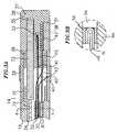
- FIG. 3A is a side cross-sectional view of the catheter tip section.
- FIG. 3B is an enlarged view of the thermocouple anchored within the tip electrodeillustrated in FIG. 3A.
- FIG. 4 is a transverse cross-sectional view of the catheter tip section along line 4-4.
- FIG. 5 is a side cross-sectional view of the catheter handle.
- In a particularly preferred embodiment of the invention, there is provided a steerablecatheter having an electromagnetic sensor. As shown in FIGs. 1-4, the
catheter 10 comprisesanelongated catheter body 12 having proximal and distal ends, atip section 14 at the distal end of thecatheter body 12, and acontrol handle 16 at the proximal end of thecatheterbody 12. - With reference to FIG. 2, the
catheter body 12 comprises an elongated tubularconstruction having a single, axial orcentral lumen 18. Thecatheter body 12 is flexible, i.e.,bendable, but substantially non-compressible along its length. Thecatheter body 12 can beof any suitable construction and made of any suitable material. A presently preferredconstruction comprises anouter wall 22 made of a polyurethane or nylon. Theouter wall 22comprises an imbedded braided mesh of stainless steel or the like to increase torsionalstiffness of thecatheter body 12 so that, when the control handle 16 is rotated, the tipsectionally of thecatheter 10 will rotate in a corresponding manner. - The outer diameter of the
catheter body 12 is not critical, but is preferably no morethan about 2.64 mm (8 french), more preferably no greater than about 2.31 mm (7 french). Likewise the thicknessof theouter wall 22 is not critical. The inner surface of theouter wall 22 is lined with astiffeningtube 20, which can be made of any suitable material that is less flexible than theouter wall 22, preferably polyimide. The stiffeningtube 20, along with the braidedouterwall 22, provides improved torsional stability while at the same time minimizing the wallthickness of the catheter, thus maximizing the diameter of thecentral lumen 18. The outerdiameter of the stiffeningtube 20 is about the same as or slightly smaller than the innerdiameter of theouter wall 22. Polyimide tubing is presently preferred because it may be verythin-walled while still providing very good stiffness. This maximizes the diameter of thecentral lumen 18 without sacrificing strength and stiffness. - A particularly preferred catheter has an
outer wall 22 with an outer diameter of fromabout 2.29 mm (0.090 inch) to about 2.39 mm (0.094 inch) and an inner diameter of from about 1.55 mm (0.061 inch) to about 1.65 mm(0.065 inch) and apolyimide stiffening tube 20 having an outer diameter of from about 1.51 mm (0.0595inch) to about 1.61 mm (0.0635 inch) and an inner diameter of about from about 1.24 mm (0.049 inch) to about 1.40 mm (0.055inch). - As shown in FIGs. 3A, 3B and 4, the
tip section 14 comprises a short section oftubing 19 having three lumens. Thetubing 19 is made of a suitable non-toxic material thatis preferably more flexible than thecatheter body 12. A presently preferred material for thetubing 19 is braided polyurethane, i.e., polyurethane with an embedded mesh of braidedstainless steel or the like. The outer diameter of thetip section 14, like that of thecatheterbody 12, is preferably no greater than about 2.64 mm (8 french), more preferably no greater than about 2.31 mm(7 french). The size of the lumens is not critical. In a particularly preferred embodiment, thetip section 14, has an outer diameter of about 2.31 mm (7 french (.092 inch)) and thefirst lumen 30 andsecond lumen 32 are generally about the same size, having a diameter of about 0.56 mm (0.022 inch),with thethird lumen 34 having a slightly larger diameter of about 0.91 mm (0.036 inch). - At the distal end of the
tip section 14 is atip electrode 36. Preferably thetipelectrode 36 has a diameter about the same as the outer diameter of thetubing 19. Apreferred tip electrode 36 has a length of about 6 mm, with an exposedsection 37 having alength of about 4 mm and astem 39, having a diameter less than the diameter of the exposedsection 37 and having a length of about 2 mm. Thestem 39 and exposedsection 37 of thetip electrode 36 are generally solid, having 3 blind holes extending from the proximal end ofthestem 39 part way into the exposedsection 37. - The
tip electrode 36 is connected to thetubing 19 by means of a generally rigidtubularplastic housing 21, preferably made of polyetheretherketone (PEEK). Thestem 39of thetip electrode 36 fits inside the distal end of theplastic housing 21 and is bonded to thehousing 21 by polyurethane glue or the like. The proximal end of theplastic housing 21 isbonded with polyurethane glue or the like to the distal end of thetubing 19 of thetipsection 14. It is understood that the tip electrode may be connected directly to thetubing 19of thecatheter tip section 14 as desired as is well known in the art. - In the embodiment shown, a
ring electrode 38 is mounted on the distal end of theplastic housing 21. Thering electrode 38 is slid over theplastic housing 21 and fixed inplace by glue or the like. If desired, additional ring electrodes may be used and can bepositioned over theplastic housing 21 or over theflexible tubing 19 of thetip section 14. - A temperature sensing means is provided for the
tip electrode 36 and, if desired, thering electrode 38. Any conventional temperature sensing means, e.g., a thermocouple orthermistor, may be used. A preferred temperature sensing means for thetip electrode 36comprises a thermocouple formed by an enameled wire pair. One wire of the wire pair is acopper wire 41, e.g., anumber 40 copper wire,meaningAWG wires plastic tubing 53, e.g., polyamide, and covered with epoxy. Theplastic tubing 53 is thenattached in the secondblind hole 33 of thetip electrode 36, by polyurethane glue or the like.Alternatively, thewires blind hole 33. - The
wires second lumen 31 in thetip section 14 andthrough thecentral lumen 18 of thecatheter body 12. Thewires - The
tip electrode 36 andring electrode 38 are each connected to aseparate lead wire 40. Thelead wires 40 extend through thesecond lumen 32 oftip section 14, thecatheterbody 12, and the control handle 16, and each terminate at its proximal end in an input jack(not shown) that may be plugged into an appropriate monitor (not shown). If desired, theportion of thelead wires 40 extending through thecatheter body 12, control handle 16 andproximal end of thetip section 14 may be enclosed or bundled within a protective tube orsheath. - The
lead wire 40 for thetip electrode 36 is anchored in the firstblind hole 31 of thetip electrode by solder or the like. Any other means for anchoring the lead wire in the tipelectrode may also be used. Alternatively, thecopper wire 41 of the thermocouple can beused as a lead wire for thetip electrode 36. - A
lead wire 40 is attached to thering electrode 38 by any conventional technique.Connection of alead wire 40 to thering electrode 38 is preferably accomplished by firstmaking a small hole through theplastic housing 21. Such a hole can be created, for example,by inserting a needle through theplastic housing 21 and heating the needle sufficiently toform a permanent hole. Alead wire 40 is then drawn through the hole by using a microhookor the like. The ends of thelead wire 40 are then stripped of any coating and soldered orwelded to the underside of thering electrode 38, which is then slid into position over thehole and fixed in place with polyurethane glue or the like. - A preferred means for attaching the
catheter body 12 to thetip section 14 is illustratedin FIG. 2. The proximal end of thetip section 14 comprises an outercircumferential notch 24that receives the inner surface of theouter wall 22 of thecatheter body 12. Thetip section 14andcatheter body 12 are attached by glue or the like. In the arrangement shown, aspacer 52lies within thecatheter body 12 between the distal end of the stiffeningtube 20 and theproximal end of thetip section 14. Thespacer 52 is preferably made of a material that isstiffer than the material of thetip section 14, e.g., polyurethane, but not as stiff as the materialof the stiffeningtube 20, e.g., polyimide. Aspacer 52 made of Teflon® is presentlypreferred. Apreferred spacer 52 has a length of from about 6.35 mm (0.25 inch) to about 19.1 mm (0.75 inch),more preferably about 12.7 mm (0.5 inch). Preferably thespacer 52 has an outer and inner diameterabout the same as the outer and inner diameters of the stiffeningtube 20. Thespacer 52provides a transition in flexibility at the junction of thecatheter body 12 andcatheter tip 14, allowing the junction of thecatheter body 12 andtip section 14 to bend smoothly withoutfolding or kinking. - The
spacer 52 is held in place by the stiffeningtube 20. The stiffeningtube 20, inturn, is held in place relative to theouter wall 22 byglue joints catheter body 12. In a preferred construction of thecatheter body 12, a force is appliedto the proximal end of the stiffeningtube 20, causing the distal end of the stiffeningtube 20to firmly butt up against and compress thespacer 52. While under compression, a first gluejoint 23 is made between the stiffeningtube 20 and theouter wall 22 by a fast drying glue,e.g. Super Glue®. Thereafter a second glue joint 25 is formed between the proximal ends ofthe stiffeningtube 20 andouter wall 22 using a slower drying but stronger glue, e.g.,polyurethane. Construction of thecatheter body 12 whereby the stiffeningtube 20 andspacer 52 are under compression has been found to be advantageous to prevent the formation ofgaps between the stiffeningtube 20 andspacer 52 or between thespacer 52 and thetip section 14 that might otherwise occur after repeated tip deflections. Such gaps are undesirablebecause they cause the catheter to crease or fold over, hindering the catheter's ability to roll. - A
puller wire 42 is provided within the catheter for deflecting thetip section 14. Thepuller wire 42 is anchored at its proximal end to the control handle 16 and anchored at itsdistal end to thetip section 14. Thepuller wire 42 is made of any suitable metal, such asstainless steel or Nitinol, and is preferably coated with Teflon® or the like. The coatingimparts lubricity to thepuller wire 42. Thepuller wire 42 preferably has a diameter rangingfrom about 0.15 mm (0.006 inches) to about 0.25 mm (0.010 inches). - A
compression coil 44 is situated with thecatheter body 12 in surrounding relation tothepuller wire 42. The compression coil extends from the proximal end of thecatheter body 12 to the proximal end of thetip section 14. Thecompression coil 44 is made of any suitablemetal, preferably stainless steel. Thecompression coil 44 is tightly wound on itself to provideflexibility, i.e., bending, but to resist compression. The inner diameter of thecompressioncoil 44 is preferably slightly larger than the diameter of thepuller wire 42. For example,when thepuller wire 42 has a diameter of about 0.18 mm (0.007 inches), thecompression coil 44preferably has an inner diameter of about 0.20 mm (0.008 inches). The Teflon® coating on thepullerwire 42 allows it to slide freely within thecompression coil 44. Along its length, the outersurface of thecompression coil 44 is covered by a flexible,non-conductive sheath 26 toprevent contact between thecompression coil 44 and thelead wires 40 within thecatheterbody 12. Anon-conductive sheath 26 made of polyimide tubing is presently preferred. - The
compression coil 44 is anchored at its proximal end to the proximal end of thestiffeningtube 20 in thecatheter body 12 by glue joint 50 and at its distal end to thetipsection 14 at a location distal to thespacer 52 by glue joint 51. Bothglue joints catheter body 12 andthesingle lumen 18. Such a hole may be formed, for example, by a needle or the like thatpunctures the wall of thecatheter body 12 and the stiffeningtube 20 which is heatedsufficiently to form a permanent hole. The glue is then introduced through the hole to theouter surface of thecompression coil 44 and wicks around the outer circumference to forma glue joint about the entire circumference of thecompression coil 44. - The
puller wire 42 extends into thefirst lumen 30 of thetip section 14. Thepullerwire 42 is anchored in the firstblind hole 31 of thetip electrode 36. Preferably, aferrule 43,made of stainless steel or the like, is crimped onto the distal end of thepuller wire 42 to addthickness to the puller wire. Theferrule 43 is the attached to the inside of the firstblindhole 31 of thetip electrode 36 with solder or the like. Alternatively, thepuller wire 42 canbe anchored to the side of thetip section 14. - With reference to FIGs. 2 and 3, within the
tip section 14, and distal to the glue joint51, the turns of the compression coil are expanded longitudinally. Such expanded turns 47are both bendable and compressible and preferably extend for a length of about 12.7 mm (0.5 inch). Thepuller wire 42 extends through the expanded turns 47 then into a plastic, preferably Teflon®,sheath 81, which prevents thepuller wire 42 from cutting into the wall of thetip section 14when thetip section 14 is deflected. - An
electromagnetic sensor 72 is contained within the distal end of thetip section 14.Theelectromagnetic sensor 72 is located within theplastic housing 21. The distal end of theelectromagnetic sensor 72 extends into the thirdblind hole 35 in thetip electrode 36 and itsproximal end extends into thetubing 19 of thetip section 14. The electromagnetic sensor isfixed in the thirdblind hole 35 by polyurethane glue or the like. If desired, the thirdblindhole 35 in thetip electrode 36 may be deeper so that the entireelectromagnetic sensor 72 islocated within the thirdblind hole 35. Alternatively, theelectromagnetic sensor 72 may bemounted proximal to thetip electrode 36. In another alternative embodiment, thetipelectrode 36 has ahollow stem 39 and theelectromagnetic sensor 72 is mounted, at leastpartially, within the hollow stem. - The
electromagnetic sensor 72 is connected to anelectromagnetic sensor cable 74,which extends through thethird lumen 34 of thetip section 14 through thecatheter body 12and out throughcontrol handle 16. Theelectromagnetic sensor cable 74 comprises multiplewires encased within a plastic covered sheath. In the control handle 16, thesensor cable 74is connected to acircuit board 64. Thecircuit board 64 amplifies the signal received fromtheelectromagnetic sensor 72 and transmits it to a computer in a form understandable by thecomputer. Because the catheter is designed for single use only, the circuit board may containan EPROM chip which shuts down the circuit board approximately 24 hours after the catheterhas been used. This prevents the catheter, or at least the electromagnetic sensor, from beingused twice. - Suitable electromagnetic sensors for use with the present invention are described, forexample, in U.S. Patent Nos. 5,558,091, 5,443,489, 5,480,422, 5,546,951, 5,568,809, and5,391,199 and International Publication No. WO 95/02995.A preferred
electromagnetic mapping sensor 72 has a lengthof from about 6 mm to about 7 mm and a diameter of about 1.3 mm. - To use the
electromagnetic sensor 72, the patient is placed in a magnetic fieldgenerated, for example, by placing a pad containing coils for generating a magnetic fieldunder the patient. A reference electromagnetic sensor is fixed relative to the patient, e.g.,taped to the patient's back, and the catheter containing a second electromagnetic sensor isadvanced into the patient's heart. Each sensor comprises three small coils which in themagnetic field generate weak electrical signals indicative of their position in the magneticfield. Signals generated by both the fixed reference sensor and the second sensor in the heartare amplified and transmitted to a computer which analyzes the signals and then displays thesignals on a monitor. By this method, the precise location of the sensor in the catheterrelative to the reference sensor can be ascertained and visually displayed. - Using this technology, the physician can visually map a heart chamber. This mappingis done by advancing the catheter tip into a heart chamber until contact is made with the heartwall. This position and electrograms are recorded and saved. The catheter tip is then movedto another position in contact with the heart wall and again the position is recorded and saved.This procedure is repeated until a three dimensional map of the heart chamber is achieved.
- The
electromagnetic mapping sensor 72 preferably is used in combination with thetipelectrode 36 andring electrode 38. By combining theelectromagnetic sensor 72 andelectrodes - The
electrode lead wire 40,thermocouple wires electromagnetic sensorcable 74 must be allowed some longitudinal movement within thecatheter body 12 so thatthey do not break when thetip section 14 is deflected. To provide for such lengthwisemovement, tunnels are provided through the glue joint 50, which fixes the proximal end ofthecompression coil 44 inside thecatheter body 12. The tunnels are formed bytransfer tubes 27, preferably made of short segments of polyimide tubing. Thetransfer tube 27 are eachapproximately 60 mm long and have outer diameters of about 0.53 mm (.021 inch) and inner diametersof about 0.48 mm (.019 inch). Thethermocouple wires electrode lead wire 40 extendthrough onetransfer tube 27 and thesensor cable 74 extends through asecond transfertube 27. Anadditional transfer tube 29 is provided at the distal end of thecatheter body 12for thethermocouples wires electrode lead wire 40 to pass through glue joint51. - Longitudinal movement of the
puller wire 42 relative to thecatheter body 12, whichresults in deflection of thetip section 12, is accomplished by a suitable manipulation of thecontrol handle 16. The distal end of the control handle 16 comprises apiston 54 with athumb control 56 for manipulating thepuller wire 42. The proximal end of thecatheter body 12 is connected to thepiston 54 by means of ashrink sleeve 28. - The
puller wire 42,lead wires 40 andelectromagnetic sensor cable 74 extend throughthepiston 54. Thepuller wire 42 is anchored to an anchor pin136, located proximal to thepiston 54. Thelead wires 40 andelectromagnetic sensor cable 74 extend though afirsttunnel 58, located near the side of the control handle 16. Theelectromagnetic sensor cable 74connects to acircuit board 64 in the proximal end of the control handle 16. Wires a computeand imaging monitor (not shown). - In another preferred embodiment constructed in accordance with the present invention,two or more puller wires are provided to enhance the ability to manipulate the tip section.In such an embodiment, a second puller wire and a surrounding second compression coilextend through the catheter body and into separate off-axis lumens in the tip section. Thelumens of the tip section receiving the puller wires may be in adjacent quadrants. The firstpuller wire is preferably anchored proximal to the anchor location of the second puller wire.The second puller wire may be anchored to the tip electrode or may be anchored to the wallof the tip section adjacent the distal end of tip section.
- The distance between the distal end of the compression coils and the anchor sites ofeach puller wire in the tip section determines the curvature of the
tip section 14 in thedirection of the puller wires. For example, an arrangement wherein the two puller wires areanchored at different distances from the distal ends of the compression coils allows a longreach curve in a first plane and a short reach curve in a plane 90° from the first, i.e., a firstcurve in one plane generally along the axis of the tip section before it is deflected and asecond curve distal to the first curve in a plane transverse, and preferably normal to the firstplane. The high torque characteristic of thecatheter tip section 12 reduces the tendency forthe deflection in one direction to deform the deflection in the other direction. - As an alternative to the above described embodiment, the puller wires may extend intodiametrically opposed off-axis lumens in the tip section. In such an embodiment, each of thepuller wires may be anchored at the same location along the length of the tip section, in whichcase the curvatures of the tip section in opposing directions are the same and the tip sectioncan be made to deflect in either direction without rotation of the catheter body.
- A particularly preferred catheter construction comprising multiple puller wiresincluding control handle construction is disclosed in U.S. Patent Application Serial No.08/924,611 entitled Omni-Directional Steerable Catheter.Such application describes a suitable control handle formanipulating two or more puller wires. The described control handle includes a centralpassage that may be expanded to accommodate the electrode lead wires, electromagneticsensor cable, optic fiber and even infusion tube. Further, an extension of the handle may beprovided to house the circuit bound for the electromagnetic sensor, e.g., in the same manneras shown in FIG. 4 herein.
- The preceding description has been presented with reference to presently preferredembodiments of the invention. Workers skilled in the art and technology to which this inventionpertains will appreciate that alterations and changes in the described structure may be practicedwithout meaningfully departing from the scope of this invention as defined by the following claims.
- Accordingly, the foregoing description should not be read as pertaining only to theprecise structures described and illustrated in the accompanying drawings, but rather should beread consistent with and as support to the following claims which are to have their fullest andfair scope.
Claims (11)
- A steerable catheter (10) comprising:a catheter body (12) having proximal and distal ends, a flexible outer wall (22), at least onelumen (18) extending therethrough, the inner surface of the outer wall being lined with a stiffening tube (20),wherein the stiffening tube is less flexible than the outer wall;a control handle (16) fixedly attached to the proximal end of the catheter body;a tip section (14) comprising a flexible tubing (19) having proximal and distal endsand at least one lumen (30; 32; 34) extending therethrough, wherein the proximal end ofthe tip section is fixedly attached to the distal end of the catheter body;a tip electrode (36) having a distal end and a proximal end mounted at the distal endof the tip section, wherein the tip electrode comprises an exposed section (37) at its distalend and a stem (39) at its proximal end, and wherein the tip electrode has at least two blindholes (31, 33, 35), each blind hole extending from the proximal end of stem (39) part wayinto the exposed section (37), each blind hole being in communication with at least onelumen in the tip section; andan electromagnetic sensor (72) having proximal and distal ends, wherein the distalend of the sensor is mounted at least partially within one (35) of the at least two blind holesin the tip electrode;means (74) for connecting the electromagnetic sensor to an imaging system; anda puller wire (42) having a proximal end and a distal end, the puller wire extendingfrom the control handle (16), through the catheter body (12) and into a lumen in the tipsection (14), wherein the distal end of the puller wire is fixedly secured within another (31)of the at east two blind holes in the tip electrode.
- A catheter according to claim 1, wherein the means for connecting theelectromagnetic sensor to an imaging system comprises an electromagnetic sensor cable(74) connected to the electromagnetic sensor, wherein the sensor cable extends through alumen in the tip section (14) through a lumen in the catheter body (12) and into the controlhandle (16).
- A catheter according to claim 1 or claim 2, wherein the tip section (14) furthercomprises a generally rigid tubular housing (21) mounted between the distal end of the tip section and the proximal end of the tip electrode (36) whereby at least part of theelectromagnetic sensor (72) is housed within the generally rigid tubular housing.
- A catheter according to claim 3, wherein the housing (21) is made ofpolyetheretherketone.
- A catheter according to claim 3 or claim 4, wherein the tip section (14) furthercomprises at least one ring electrode (38) mounted on the generally rigid tubularhousing (21).
- A catheter according to any preceding claim, wherein the catheter body (12) has asingle lumen (18).
- A catheter according to any preceding claim, wherein the control handle (16)comprises a first member (54) fixedly attached to the proximal end of the catheter body(12) and a second member (136) that is movable relative to the first member.
- A catheter according to claim 7, wherein the proximal end of the puller wire (42) isfixedly secured to the second member (136) of the control handle (16), wherebymanipulation of the first member (54) of the control handle relative to the second memberof the control handle moves the puller wire relative to the catheter body (12), resulting indeflection of the tip section (14).
- A catheter according to any preceding claim, further comprising a temperaturesensor (41, 45) monitoring the temperature of the tip electrode (36).
- A catheter according to claim 9, wherein the temperature sensor (41, 45) isanchored within a third blind hole (33) in the tip electrode (36).
- A catheter according to any preceding claim, wherein the stem (39) has a diameterless than the diameter of the proximal end of the exposed section (37).
Applications Claiming Priority (2)
| Application Number | Priority Date | Filing Date | Title |
|---|---|---|---|
| US08/982,064US5938603A (en) | 1997-12-01 | 1997-12-01 | Steerable catheter with electromagnetic sensor |
| US982064 | 1997-12-01 |
Publications (3)
| Publication Number | Publication Date |
|---|---|
| EP0928600A2 EP0928600A2 (en) | 1999-07-14 |
| EP0928600A3 EP0928600A3 (en) | 1999-08-25 |
| EP0928600B1true EP0928600B1 (en) | 2005-03-23 |
Family
ID=25528818
Family Applications (1)
| Application Number | Title | Priority Date | Filing Date |
|---|---|---|---|
| EP98309777AExpired - LifetimeEP0928600B1 (en) | 1997-12-01 | 1998-11-30 | Steerable catheter with electromagnetic sensor |
Country Status (4)
| Country | Link |
|---|---|
| US (1) | US5938603A (en) |
| EP (1) | EP0928600B1 (en) |
| JP (1) | JP4209018B2 (en) |
| DE (1) | DE69829455T2 (en) |
Cited By (3)
| Publication number | Priority date | Publication date | Assignee | Title |
|---|---|---|---|---|
| US8696549B2 (en) | 2010-08-20 | 2014-04-15 | Veran Medical Technologies, Inc. | Apparatus and method for four dimensional soft tissue navigation in endoscopic applications |
| US9138165B2 (en) | 2012-02-22 | 2015-09-22 | Veran Medical Technologies, Inc. | Systems, methods and devices for forming respiratory-gated point cloud for four dimensional soft tissue navigation |
| US9218664B2 (en) | 2005-09-13 | 2015-12-22 | Veran Medical Technologies, Inc. | Apparatus and method for image guided accuracy verification |
Families Citing this family (146)
| Publication number | Priority date | Publication date | Assignee | Title |
|---|---|---|---|---|
| FR2652928B1 (en) | 1989-10-05 | 1994-07-29 | Diadix Sa | INTERACTIVE LOCAL INTERVENTION SYSTEM WITHIN A AREA OF A NON-HOMOGENEOUS STRUCTURE. |
| AU675077B2 (en) | 1992-08-14 | 1997-01-23 | British Telecommunications Public Limited Company | Position location system |
| DE69531994T2 (en) | 1994-09-15 | 2004-07-22 | OEC Medical Systems, Inc., Boston | SYSTEM FOR POSITION DETECTION BY MEANS OF A REFERENCE UNIT ATTACHED TO A PATIENT'S HEAD FOR USE IN THE MEDICAL AREA |
| US5592939A (en) | 1995-06-14 | 1997-01-14 | Martinelli; Michael A. | Method and system for navigating a catheter probe |
| US6024739A (en)* | 1997-09-05 | 2000-02-15 | Cordis Webster, Inc. | Method for detecting and revascularizing ischemic myocardial tissue |
| US6226548B1 (en) | 1997-09-24 | 2001-05-01 | Surgical Navigation Technologies, Inc. | Percutaneous registration apparatus and method for use in computer-assisted surgical navigation |
| US6021343A (en) | 1997-11-20 | 2000-02-01 | Surgical Navigation Technologies | Image guided awl/tap/screwdriver |
| US6348058B1 (en) | 1997-12-12 | 2002-02-19 | Surgical Navigation Technologies, Inc. | Image guided spinal surgery guide, system, and method for use thereof |
| US6173199B1 (en)* | 1998-05-05 | 2001-01-09 | Syncro Medical Innovations, Inc. | Method and apparatus for intubation of a patient |
| US6064905A (en)* | 1998-06-18 | 2000-05-16 | Cordis Webster, Inc. | Multi-element tip electrode mapping catheter |
| US6477400B1 (en) | 1998-08-20 | 2002-11-05 | Sofamor Danek Holdings, Inc. | Fluoroscopic image guided orthopaedic surgery system with intraoperative registration |
| US6061588A (en)* | 1998-09-29 | 2000-05-09 | Advanced Cardiovascular Systems, Inc. | Catheter apparatus for positioning a wire |
| US6470207B1 (en) | 1999-03-23 | 2002-10-22 | Surgical Navigation Technologies, Inc. | Navigational guidance via computer-assisted fluoroscopic imaging |
| US6491699B1 (en) | 1999-04-20 | 2002-12-10 | Surgical Navigation Technologies, Inc. | Instrument guidance method and system for image guided surgery |
| US6474341B1 (en) | 1999-10-28 | 2002-11-05 | Surgical Navigation Technologies, Inc. | Surgical communication and power system |
| US8644907B2 (en) | 1999-10-28 | 2014-02-04 | Medtronic Navigaton, Inc. | Method and apparatus for surgical navigation |
| US6379302B1 (en) | 1999-10-28 | 2002-04-30 | Surgical Navigation Technologies Inc. | Navigation information overlay onto ultrasound imagery |
| US6381485B1 (en) | 1999-10-28 | 2002-04-30 | Surgical Navigation Technologies, Inc. | Registration of human anatomy integrated for electromagnetic localization |
| US7366562B2 (en) | 2003-10-17 | 2008-04-29 | Medtronic Navigation, Inc. | Method and apparatus for surgical navigation |
| US6235038B1 (en) | 1999-10-28 | 2001-05-22 | Medtronic Surgical Navigation Technologies | System for translation of electromagnetic and optical localization systems |
| US8239001B2 (en) | 2003-10-17 | 2012-08-07 | Medtronic Navigation, Inc. | Method and apparatus for surgical navigation |
| US11331150B2 (en) | 1999-10-28 | 2022-05-17 | Medtronic Navigation, Inc. | Method and apparatus for surgical navigation |
| US6499488B1 (en) | 1999-10-28 | 2002-12-31 | Winchester Development Associates | Surgical sensor |
| US6493573B1 (en) | 1999-10-28 | 2002-12-10 | Winchester Development Associates | Method and system for navigating a catheter probe in the presence of field-influencing objects |
| US6892091B1 (en) | 2000-02-18 | 2005-05-10 | Biosense, Inc. | Catheter, method and apparatus for generating an electrical map of a chamber of the heart |
| US6725080B2 (en) | 2000-03-01 | 2004-04-20 | Surgical Navigation Technologies, Inc. | Multiple cannula image guided tool for image guided procedures |
| US6535756B1 (en) | 2000-04-07 | 2003-03-18 | Surgical Navigation Technologies, Inc. | Trajectory storage apparatus and method for surgical navigation system |
| EP3111983A1 (en)* | 2000-04-21 | 2017-01-04 | Covidien LP | System and method for intravascular catheter navigation |
| US7085400B1 (en) | 2000-06-14 | 2006-08-01 | Surgical Navigation Technologies, Inc. | System and method for image based sensor calibration |
| US6400981B1 (en) | 2000-06-21 | 2002-06-04 | Biosense, Inc. | Rapid mapping of electrical activity in the heart |
| US6405067B1 (en) | 2000-07-07 | 2002-06-11 | Biosense Webster, Inc. | Catheter with tip electrode having a recessed ring electrode mounted thereon |
| US20040087877A1 (en)* | 2000-08-23 | 2004-05-06 | Besz William John | Catheter locator apparatus and method of use |
| US20020103430A1 (en)* | 2001-01-29 | 2002-08-01 | Hastings Roger N. | Catheter navigation within an MR imaging device |
| US6584345B2 (en) | 2001-03-13 | 2003-06-24 | Biosense, Inc. | Apparatus and method for measuring a plurality of electrical signals from the body of a patient |
| US6636757B1 (en) | 2001-06-04 | 2003-10-21 | Surgical Navigation Technologies, Inc. | Method and apparatus for electromagnetic navigation of a surgical probe near a metal object |
| US6730082B2 (en)* | 2001-07-09 | 2004-05-04 | Scimed Life Systems, Inc. | Two-piece distal catheter assembly |
| US6947786B2 (en) | 2002-02-28 | 2005-09-20 | Surgical Navigation Technologies, Inc. | Method and apparatus for perspective inversion |
| US6990368B2 (en) | 2002-04-04 | 2006-01-24 | Surgical Navigation Technologies, Inc. | Method and apparatus for virtual digital subtraction angiography |
| US7998062B2 (en) | 2004-03-29 | 2011-08-16 | Superdimension, Ltd. | Endoscope structures and techniques for navigating to a target in branched structure |
| US6892090B2 (en) | 2002-08-19 | 2005-05-10 | Surgical Navigation Technologies, Inc. | Method and apparatus for virtual endoscopy |
| US6957101B2 (en) | 2002-08-21 | 2005-10-18 | Joshua Porath | Transient event mapping in the heart |
| US7599730B2 (en) | 2002-11-19 | 2009-10-06 | Medtronic Navigation, Inc. | Navigation system for cardiac therapies |
| US7697972B2 (en) | 2002-11-19 | 2010-04-13 | Medtronic Navigation, Inc. | Navigation system for cardiac therapies |
| US7072703B2 (en) | 2002-12-31 | 2006-07-04 | Cardiac Pacemakers, Inc. | Medical device with force monitoring features and method therefor |
| US7819866B2 (en) | 2003-01-21 | 2010-10-26 | St. Jude Medical, Atrial Fibrillation Division, Inc. | Ablation catheter and electrode |
| US7660623B2 (en) | 2003-01-30 | 2010-02-09 | Medtronic Navigation, Inc. | Six degree of freedom alignment display for medical procedures |
| US7542791B2 (en) | 2003-01-30 | 2009-06-02 | Medtronic Navigation, Inc. | Method and apparatus for preplanning a surgical procedure |
| JP4698128B2 (en)* | 2003-03-28 | 2011-06-08 | テルモ株式会社 | Catheter with puncture sensor |
| US7570791B2 (en) | 2003-04-25 | 2009-08-04 | Medtronic Navigation, Inc. | Method and apparatus for performing 2D to 3D registration |
| US7218970B2 (en)* | 2003-06-20 | 2007-05-15 | Cardiac Pacemakers, Inc. | System for medical lead tunneling |
| US7101362B2 (en)* | 2003-07-02 | 2006-09-05 | St. Jude Medical, Atrial Fibrillation Division, Inc. | Steerable and shapable catheter employing fluid force |
| US7235070B2 (en) | 2003-07-02 | 2007-06-26 | St. Jude Medical, Atrial Fibrillation Division, Inc. | Ablation fluid manifold for ablation catheter |
| ITRM20030376A1 (en) | 2003-07-31 | 2005-02-01 | Univ Roma | PROCEDURE FOR THE ISOLATION AND EXPANSION OF CARDIOC STAMIN CELLS FROM BIOPSIA. |
| US7313430B2 (en) | 2003-08-28 | 2007-12-25 | Medtronic Navigation, Inc. | Method and apparatus for performing stereotactic surgery |
| ATE418306T1 (en)* | 2003-09-02 | 2009-01-15 | Abbott Lab | INTRODUCTION SYSTEM FOR A MEDICAL DEVICE |
| EP2113189B1 (en) | 2003-09-15 | 2013-09-04 | Covidien LP | System of accessories for use with bronchoscopes |
| EP2316328B1 (en) | 2003-09-15 | 2012-05-09 | Super Dimension Ltd. | Wrap-around holding device for use with bronchoscopes |
| US7835778B2 (en) | 2003-10-16 | 2010-11-16 | Medtronic Navigation, Inc. | Method and apparatus for surgical navigation of a multiple piece construct for implantation |
| US7840253B2 (en) | 2003-10-17 | 2010-11-23 | Medtronic Navigation, Inc. | Method and apparatus for surgical navigation |
| US8764725B2 (en) | 2004-02-09 | 2014-07-01 | Covidien Lp | Directional anchoring mechanism, method and applications thereof |
| US8046049B2 (en) | 2004-02-23 | 2011-10-25 | Biosense Webster, Inc. | Robotically guided catheter |
| US7567834B2 (en) | 2004-05-03 | 2009-07-28 | Medtronic Navigation, Inc. | Method and apparatus for implantation between two vertebral bodies |
| EP1761187B1 (en)* | 2004-05-17 | 2011-11-30 | C.R. Bard, Inc. | Irrigated catheter |
| WO2005113057A1 (en)* | 2004-05-17 | 2005-12-01 | C. R. Bard, Inc. | Articulated catheter |
| US7717875B2 (en)* | 2004-07-20 | 2010-05-18 | St. Jude Medical, Atrial Fibrillation Division, Inc. | Steerable catheter with hydraulic or pneumatic actuator |
| US7636595B2 (en) | 2004-10-28 | 2009-12-22 | Medtronic Navigation, Inc. | Method and apparatus for calibrating non-linear instruments |
| US11660317B2 (en) | 2004-11-08 | 2023-05-30 | The Johns Hopkins University | Compositions comprising cardiosphere-derived cells for use in cell therapy |
| US7655014B2 (en)* | 2004-12-06 | 2010-02-02 | Cameron Health, Inc. | Apparatus and method for subcutaneous electrode insertion |
| US7976518B2 (en) | 2005-01-13 | 2011-07-12 | Corpak Medsystems, Inc. | Tubing assembly and signal generator placement control device and method for use with catheter guidance systems |
| US20070016069A1 (en) | 2005-05-06 | 2007-01-18 | Sorin Grunwald | Ultrasound sensor |
| US20090118612A1 (en) | 2005-05-06 | 2009-05-07 | Sorin Grunwald | Apparatus and Method for Vascular Access |
| US7819868B2 (en) | 2005-06-21 | 2010-10-26 | St. Jude Medical, Atrial Fibrilation Division, Inc. | Ablation catheter with fluid distribution structures |
| US7835784B2 (en) | 2005-09-21 | 2010-11-16 | Medtronic Navigation, Inc. | Method and apparatus for positioning a reference frame |
| US7957789B2 (en)* | 2005-12-30 | 2011-06-07 | Medtronic, Inc. | Therapy delivery system including a navigation element |
| US9168102B2 (en) | 2006-01-18 | 2015-10-27 | Medtronic Navigation, Inc. | Method and apparatus for providing a container to a sterile environment |
| US8112292B2 (en) | 2006-04-21 | 2012-02-07 | Medtronic Navigation, Inc. | Method and apparatus for optimizing a therapy |
| US8197494B2 (en) | 2006-09-08 | 2012-06-12 | Corpak Medsystems, Inc. | Medical device position guidance system with wireless connectivity between a noninvasive device and an invasive device |
| US8660635B2 (en) | 2006-09-29 | 2014-02-25 | Medtronic, Inc. | Method and apparatus for optimizing a computer assisted surgical procedure |
| US7848822B2 (en)* | 2006-11-14 | 2010-12-07 | Cardiac Pacemakers, Inc. | Cardiac force sensor and methods of use |
| US8480653B2 (en) | 2007-05-23 | 2013-07-09 | Biosense Webster, Inc. | Magnetically guided catheter with concentric needle port |
| US8603046B2 (en)* | 2007-05-23 | 2013-12-10 | Biosense Webster, Inc. | Automated injection catheter device and system |
| JP5660890B2 (en) | 2007-06-26 | 2015-01-28 | バソノバ・インコーポレイテッドVasonova, Inc. | Vascular access and guidance system |
| JP2010537744A (en)* | 2007-08-30 | 2010-12-09 | シンクロ メディカル イノベーションズ, インコーポレイテッド | Guided catheter with removable magnetic guide |
| US8905920B2 (en) | 2007-09-27 | 2014-12-09 | Covidien Lp | Bronchoscope adapter and method |
| US8114144B2 (en)* | 2007-10-17 | 2012-02-14 | Abbott Cardiovascular Systems Inc. | Rapid-exchange retractable sheath self-expanding delivery system with incompressible inner member and flexible distal assembly |
| ATE499055T1 (en)* | 2007-12-18 | 2011-03-15 | Storz Medical Ag | NAVIGATION WITH FOCUSED PRESSURE WAVE TREATMENT |
| US8175679B2 (en) | 2007-12-26 | 2012-05-08 | St. Jude Medical, Atrial Fibrillation Division, Inc. | Catheter electrode that can simultaneously emit electrical energy and facilitate visualization by magnetic resonance imaging |
| US9675410B2 (en)* | 2007-12-28 | 2017-06-13 | St. Jude Medical, Atrial Fibrillation Division, Inc. | Flexible polymer electrode for MRI-guided positioning and radio frequency ablation |
| US9320570B2 (en) | 2007-12-28 | 2016-04-26 | St. Jude Medical, Atrial Fibrillation Division, Inc. | System and method for preventing collateral damage with interventional medical procedures |
| WO2009122273A2 (en) | 2008-04-03 | 2009-10-08 | Superdimension, Ltd. | Magnetic interference detection system and method |
| EP2297673B1 (en) | 2008-06-03 | 2020-04-22 | Covidien LP | Feature-based registration method |
| US8218847B2 (en) | 2008-06-06 | 2012-07-10 | Superdimension, Ltd. | Hybrid registration method |
| US8932207B2 (en) | 2008-07-10 | 2015-01-13 | Covidien Lp | Integrated multi-functional endoscopic tool |
| EP2331182A1 (en)* | 2008-09-02 | 2011-06-15 | Syncro Medical Innovations, Inc. | Magnetic device for guiding catheter and method of use therefor |
| US8165658B2 (en) | 2008-09-26 | 2012-04-24 | Medtronic, Inc. | Method and apparatus for positioning a guide relative to a base |
| US8175681B2 (en) | 2008-12-16 | 2012-05-08 | Medtronic Navigation Inc. | Combination of electromagnetic and electropotential localization |
| US8372033B2 (en) | 2008-12-31 | 2013-02-12 | St. Jude Medical, Atrial Fibrillation Division, Inc. | Catheter having proximal heat sensitive deflection mechanism and related methods of use and manufacturing |
| US8808345B2 (en) | 2008-12-31 | 2014-08-19 | Medtronic Ardian Luxembourg S.A.R.L. | Handle assemblies for intravascular treatment devices and associated systems and methods |
| US8864744B2 (en)* | 2009-02-25 | 2014-10-21 | St. Jude Medical, Atrial Fibrillation Division, Inc. | Medical device having laminate-coated braid assembly |
| US8611984B2 (en) | 2009-04-08 | 2013-12-17 | Covidien Lp | Locatable catheter |
| US8494613B2 (en) | 2009-08-31 | 2013-07-23 | Medtronic, Inc. | Combination localization system |
| US8494614B2 (en) | 2009-08-31 | 2013-07-23 | Regents Of The University Of Minnesota | Combination localization system |
| US9249392B2 (en) | 2010-04-30 | 2016-02-02 | Cedars-Sinai Medical Center | Methods and compositions for maintaining genomic stability in cultured stem cells |
| US9845457B2 (en) | 2010-04-30 | 2017-12-19 | Cedars-Sinai Medical Center | Maintenance of genomic stability in cultured stem cells |
| US10582834B2 (en) | 2010-06-15 | 2020-03-10 | Covidien Lp | Locatable expandable working channel and method |
| MX350734B (en) | 2010-09-08 | 2017-09-15 | Covidien Lp | Catheter with imaging assembly. |
| EP2637568B1 (en) | 2010-11-08 | 2017-04-12 | Vasonova, Inc. | Endovascular navigation system |
| US20120123326A1 (en)* | 2010-11-12 | 2012-05-17 | Christian Steven C | Catheter systems with distal end function, such as distal deflection, using remote actuation or low input force |
| US9028441B2 (en) | 2011-09-08 | 2015-05-12 | Corpak Medsystems, Inc. | Apparatus and method used with guidance system for feeding and suctioning |
| US9693759B2 (en)* | 2011-11-16 | 2017-07-04 | Coloplast A/S | Operating device with a control handle and a flexible element connected to the control handle |
| JP2013171823A (en)* | 2012-02-23 | 2013-09-02 | Hakko Electric Co Ltd | Thermoelectric needle |
| EP2846701A4 (en) | 2012-05-07 | 2016-01-27 | Vasonova Inc | Right atrium indicator |
| EP2861238A4 (en) | 2012-06-05 | 2016-03-16 | Capricor Inc | Optimized methods for generation of cardiac stem cells from cardiac tissue and their use in cardiac therapy |
| EP2882445B1 (en) | 2012-08-13 | 2019-04-24 | Cedars-Sinai Medical Center | Exosomes and micro-ribonucleic acids for tissue regeneration |
| USD717340S1 (en) | 2012-09-07 | 2014-11-11 | Covidien Lp | Display screen with enteral feeding icon |
| US9198835B2 (en) | 2012-09-07 | 2015-12-01 | Covidien Lp | Catheter with imaging assembly with placement aid and related methods therefor |
| USD716841S1 (en) | 2012-09-07 | 2014-11-04 | Covidien Lp | Display screen with annotate file icon |
| USD735343S1 (en) | 2012-09-07 | 2015-07-28 | Covidien Lp | Console |
| US9517184B2 (en) | 2012-09-07 | 2016-12-13 | Covidien Lp | Feeding tube with insufflation device and related methods therefor |
| US20150305650A1 (en) | 2014-04-23 | 2015-10-29 | Mark Hunter | Apparatuses and methods for endobronchial navigation to and confirmation of the location of a target tissue and percutaneous interception of the target tissue |
| US20150305612A1 (en) | 2014-04-23 | 2015-10-29 | Mark Hunter | Apparatuses and methods for registering a real-time image feed from an imaging device to a steerable catheter |
| US10952593B2 (en) | 2014-06-10 | 2021-03-23 | Covidien Lp | Bronchoscope adapter |
| JP6878274B2 (en) | 2014-10-03 | 2021-05-26 | シーダーズ−サイナイ・メディカル・センターCedars−Sinai Medical Center | Myocardial cell-derived cells and exosomes secreted by such cells in the treatment of muscular dystrophy |
| US10285754B2 (en)* | 2015-05-18 | 2019-05-14 | Biosense Webster (Israel) Ltd. | Catheter with coaxial thermocouple |
| US10426555B2 (en) | 2015-06-03 | 2019-10-01 | Covidien Lp | Medical instrument with sensor for use in a system and method for electromagnetic navigation |
| US10575754B2 (en) | 2015-09-23 | 2020-03-03 | Covidien Lp | Catheter having a sensor and an extended working channel |
| US9962134B2 (en) | 2015-10-28 | 2018-05-08 | Medtronic Navigation, Inc. | Apparatus and method for maintaining image quality while minimizing X-ray dosage of a patient |
| EP3402543B1 (en) | 2016-01-11 | 2021-09-08 | Cedars-Sinai Medical Center | Cardiosphere-derived cells and exosomes secreted by such cells in the treatment of heart failure with preserved ejection fraction |
| USD798443S1 (en) | 2016-05-03 | 2017-09-26 | Coloplast A/S | Videoscope handle |
| US10478254B2 (en) | 2016-05-16 | 2019-11-19 | Covidien Lp | System and method to access lung tissue |
| WO2017210652A1 (en) | 2016-06-03 | 2017-12-07 | Cedars-Sinai Medical Center | Cdc-derived exosomes for treatment of ventricular tachyarrythmias |
| EP3515459A4 (en) | 2016-09-20 | 2020-08-05 | Cedars-Sinai Medical Center | CARDIOSPHERIC CELLS AND THEIR EXTRACELLULAR VESICLES TO DELAY OR REVERSE THE AGING PROCESS AND AGE-RELATED DISEASES |
| US10751126B2 (en) | 2016-10-28 | 2020-08-25 | Covidien Lp | System and method for generating a map for electromagnetic navigation |
| US10638952B2 (en) | 2016-10-28 | 2020-05-05 | Covidien Lp | Methods, systems, and computer-readable media for calibrating an electromagnetic navigation system |
| US10722311B2 (en) | 2016-10-28 | 2020-07-28 | Covidien Lp | System and method for identifying a location and/or an orientation of an electromagnetic sensor based on a map |
| US10517505B2 (en) | 2016-10-28 | 2019-12-31 | Covidien Lp | Systems, methods, and computer-readable media for optimizing an electromagnetic navigation system |
| US10792106B2 (en) | 2016-10-28 | 2020-10-06 | Covidien Lp | System for calibrating an electromagnetic navigation system |
| US10615500B2 (en) | 2016-10-28 | 2020-04-07 | Covidien Lp | System and method for designing electromagnetic navigation antenna assemblies |
| US10418705B2 (en) | 2016-10-28 | 2019-09-17 | Covidien Lp | Electromagnetic navigation antenna assembly and electromagnetic navigation system including the same |
| US10446931B2 (en) | 2016-10-28 | 2019-10-15 | Covidien Lp | Electromagnetic navigation antenna assembly and electromagnetic navigation system including the same |
| AU2018255346B2 (en) | 2017-04-19 | 2024-05-02 | Capricor, Inc. | Methods and compositions for treating skeletal muscular dystrophy |
| US11219489B2 (en) | 2017-10-31 | 2022-01-11 | Covidien Lp | Devices and systems for providing sensors in parallel with medical tools |
| WO2019126068A1 (en) | 2017-12-20 | 2019-06-27 | Cedars-Sinai Medical Center | Engineered extracellular vesicles for enhanced tissue delivery |
| WO2019152549A1 (en) | 2018-02-05 | 2019-08-08 | Cedars-Sinai Medical Center | Methods for therapeutic use of exosomes and y-rnas |
| US12089902B2 (en) | 2019-07-30 | 2024-09-17 | Coviden Lp | Cone beam and 3D fluoroscope lung navigation |
| TWI747079B (en)* | 2019-11-19 | 2021-11-21 | 財團法人資訊工業策進會 | Measurement system and method for positioning precision of a robot arm |
Family Cites Families (14)
| Publication number | Priority date | Publication date | Assignee | Title |
|---|---|---|---|---|
| US4960134A (en)* | 1988-11-18 | 1990-10-02 | Webster Wilton W Jr | Steerable catheter |
| US5242441A (en)* | 1992-02-24 | 1993-09-07 | Boaz Avitall | Deflectable catheter with rotatable tip electrode |
| US5555883A (en)* | 1992-02-24 | 1996-09-17 | Avitall; Boaz | Loop electrode array mapping and ablation catheter for cardiac chambers |
| US5318525A (en)* | 1992-04-10 | 1994-06-07 | Medtronic Cardiorhythm | Steerable electrode catheter |
| US5462544A (en)* | 1993-05-05 | 1995-10-31 | Energy Life System Corporation | Continuous heart tissue mapping and lasing catheter |
| NL9301018A (en)* | 1993-06-11 | 1995-01-02 | Cordis Europ | Controlled bendable catheter. |
| US5391199A (en)* | 1993-07-20 | 1995-02-21 | Biosense, Inc. | Apparatus and method for treating cardiac arrhythmias |
| US5431168A (en)* | 1993-08-23 | 1995-07-11 | Cordis-Webster, Inc. | Steerable open-lumen catheter |
| US5558091A (en) | 1993-10-06 | 1996-09-24 | Biosense, Inc. | Magnetic determination of position and orientation |
| US5454370A (en)* | 1993-12-03 | 1995-10-03 | Avitall; Boaz | Mapping and ablation electrode configuration |
| US5715832A (en)* | 1995-02-28 | 1998-02-10 | Boston Scientific Corporation | Deflectable biopsy catheter |
| JP3782113B2 (en)* | 1995-06-12 | 2006-06-07 | コーディス ウェブスター,インコーポレイティド | Catheter with electromagnetic guidance sensor |
| US5755760A (en)* | 1996-03-11 | 1998-05-26 | Medtronic, Inc. | Deflectable catheter |
| EP0900547B1 (en)* | 1997-09-05 | 2007-05-30 | Biosense Webster, Inc. | Steerable catheter for detecting and revascularizing ischemic myocardial tissue |
- 1997
- 1997-12-01USUS08/982,064patent/US5938603A/ennot_activeExpired - Lifetime
- 1998
- 1998-11-30DEDE69829455Tpatent/DE69829455T2/ennot_activeExpired - Lifetime
- 1998-11-30JPJP35379998Apatent/JP4209018B2/ennot_activeExpired - Lifetime
- 1998-11-30EPEP98309777Apatent/EP0928600B1/ennot_activeExpired - Lifetime
Cited By (4)
| Publication number | Priority date | Publication date | Assignee | Title |
|---|---|---|---|---|
| US9218664B2 (en) | 2005-09-13 | 2015-12-22 | Veran Medical Technologies, Inc. | Apparatus and method for image guided accuracy verification |
| US9218663B2 (en) | 2005-09-13 | 2015-12-22 | Veran Medical Technologies, Inc. | Apparatus and method for automatic image guided accuracy verification |
| US8696549B2 (en) | 2010-08-20 | 2014-04-15 | Veran Medical Technologies, Inc. | Apparatus and method for four dimensional soft tissue navigation in endoscopic applications |
| US9138165B2 (en) | 2012-02-22 | 2015-09-22 | Veran Medical Technologies, Inc. | Systems, methods and devices for forming respiratory-gated point cloud for four dimensional soft tissue navigation |
Also Published As
| Publication number | Publication date |
|---|---|
| DE69829455D1 (en) | 2005-04-28 |
| EP0928600A3 (en) | 1999-08-25 |
| JPH11285534A (en) | 1999-10-19 |
| EP0928600A2 (en) | 1999-07-14 |
| US5938603A (en) | 1999-08-17 |
| JP4209018B2 (en) | 2009-01-14 |
| DE69829455T2 (en) | 2006-04-13 |
Similar Documents
| Publication | Publication Date | Title |
|---|---|---|
| EP0928600B1 (en) | Steerable catheter with electromagnetic sensor | |
| US6602242B1 (en) | Irrigated tip catheter | |
| US6171277B1 (en) | Bi-directional control handle for steerable catheter | |
| EP1319364B1 (en) | Multiple electrode mapping catheter with location sensor | |
| EP1319365B1 (en) | Multiple electrode mapping catheter with improved expansion mechanism | |
| US6183463B1 (en) | Bidirectional steerable cathether with bidirectional control handle | |
| US6210407B1 (en) | Bi-directional electrode catheter | |
| US6374476B1 (en) | Method for making a catheter tip section | |
| EP0965302B1 (en) | Multi-element tip electrode mapping catheter | |
| US6551271B2 (en) | Asymmetrical bidirectional steerable catheter | |
| US6203507B1 (en) | Deflectable catheter with ergonomic handle | |
| US5935124A (en) | Tip electrode with multiple temperature sensors |
Legal Events
| Date | Code | Title | Description |
|---|---|---|---|
| PUAI | Public reference made under article 153(3) epc to a published international application that has entered the european phase | Free format text:ORIGINAL CODE: 0009012 | |
| PUAL | Search report despatched | Free format text:ORIGINAL CODE: 0009013 | |
| AK | Designated contracting states | Kind code of ref document:A2 Designated state(s):BE DE FR GB IE IT NL | |
| AX | Request for extension of the european patent | Free format text:AL;LT;LV;MK;RO;SI | |
| AK | Designated contracting states | Kind code of ref document:A3 Designated state(s):AT BE CH CY DE DK ES FI FR GB GR IE IT LI LU MC NL PT SE | |
| AX | Request for extension of the european patent | Free format text:AL;LT;LV;MK;RO;SI | |
| RIC1 | Information provided on ipc code assigned before grant | Free format text:6A 61B 17/38 A, 6A 61M 25/01 B, 6A 61B 5/06 B, 6A 61B 5/042 B, 6A 61B 5/00 B, 6A 61B 17/36 B | |
| 17P | Request for examination filed | Effective date:20000131 | |
| AKX | Designation fees paid | Free format text:BE DE FR GB IE IT NL | |
| 17Q | First examination report despatched | Effective date:20030611 | |
| GRAP | Despatch of communication of intention to grant a patent | Free format text:ORIGINAL CODE: EPIDOSNIGR1 | |
| RIC1 | Information provided on ipc code assigned before grant | Ipc:7A 61B 5/042 B Ipc:7A 61B 5/06 B Ipc:7A 61M 25/01 A | |
| GRAS | Grant fee paid | Free format text:ORIGINAL CODE: EPIDOSNIGR3 | |
| GRAA | (expected) grant | Free format text:ORIGINAL CODE: 0009210 | |
| RAP1 | Party data changed (applicant data changed or rights of an application transferred) | Owner name:BIOSENSE WEBSTER, INC. | |
| AK | Designated contracting states | Kind code of ref document:B1 Designated state(s):BE DE FR GB IE IT NL | |
| PG25 | Lapsed in a contracting state [announced via postgrant information from national office to epo] | Ref country code:IT Free format text:LAPSE BECAUSE OF FAILURE TO SUBMIT A TRANSLATION OF THE DESCRIPTION OR TO PAY THE FEE WITHIN THE PRESCRIBED TIME-LIMIT;WARNING: LAPSES OF ITALIAN PATENTS WITH EFFECTIVE DATE BEFORE 2007 MAY HAVE OCCURRED AT ANY TIME BEFORE 2007. THE CORRECT EFFECTIVE DATE MAY BE DIFFERENT FROM THE ONE RECORDED. Effective date:20050323 | |
| REG | Reference to a national code | Ref country code:GB Ref legal event code:FG4D | |
| REG | Reference to a national code | Ref country code:IE Ref legal event code:FG4D | |
| REF | Corresponds to: | Ref document number:69829455 Country of ref document:DE Date of ref document:20050428 Kind code of ref document:P | |
| PLBE | No opposition filed within time limit | Free format text:ORIGINAL CODE: 0009261 | |
| STAA | Information on the status of an ep patent application or granted ep patent | Free format text:STATUS: NO OPPOSITION FILED WITHIN TIME LIMIT | |
| ET | Fr: translation filed | ||
| 26N | No opposition filed | Effective date:20051227 | |
| REG | Reference to a national code | Ref country code:FR Ref legal event code:PLFP Year of fee payment:19 | |
| REG | Reference to a national code | Ref country code:FR Ref legal event code:PLFP Year of fee payment:20 | |
| PGFP | Annual fee paid to national office [announced via postgrant information from national office to epo] | Ref country code:DE Payment date:20171121 Year of fee payment:20 Ref country code:FR Payment date:20171012 Year of fee payment:20 Ref country code:NL Payment date:20171115 Year of fee payment:20 | |
| PGFP | Annual fee paid to national office [announced via postgrant information from national office to epo] | Ref country code:GB Payment date:20171129 Year of fee payment:20 Ref country code:BE Payment date:20171013 Year of fee payment:20 Ref country code:IE Payment date:20171109 Year of fee payment:20 | |
| REG | Reference to a national code | Ref country code:DE Ref legal event code:R071 Ref document number:69829455 Country of ref document:DE | |
| REG | Reference to a national code | Ref country code:NL Ref legal event code:MK Effective date:20181129 | |
| REG | Reference to a national code | Ref country code:GB Ref legal event code:PE20 Expiry date:20181129 | |
| REG | Reference to a national code | Ref country code:BE Ref legal event code:MK Effective date:20181130 | |
| REG | Reference to a national code | Ref country code:IE Ref legal event code:MK9A | |
| PG25 | Lapsed in a contracting state [announced via postgrant information from national office to epo] | Ref country code:IE Free format text:LAPSE BECAUSE OF EXPIRATION OF PROTECTION Effective date:20181130 | |
| PG25 | Lapsed in a contracting state [announced via postgrant information from national office to epo] | Ref country code:GB Free format text:LAPSE BECAUSE OF EXPIRATION OF PROTECTION Effective date:20181129 |