EP0928443B1 - A network accessible interface for a process control network - Google Patents
A network accessible interface for a process control networkDownload PDFInfo
- Publication number
- EP0928443B1 EP0928443B1EP97945427AEP97945427AEP0928443B1EP 0928443 B1EP0928443 B1EP 0928443B1EP 97945427 AEP97945427 AEP 97945427AEP 97945427 AEP97945427 AEP 97945427AEP 0928443 B1EP0928443 B1EP 0928443B1
- Authority
- EP
- European Patent Office
- Prior art keywords
- communication
- data
- process control
- interface
- control system
- Prior art date
- Legal status (The legal status is an assumption and is not a legal conclusion. Google has not performed a legal analysis and makes no representation as to the accuracy of the status listed.)
- Expired - Lifetime
Links
Images


Classifications
- G—PHYSICS
- G05—CONTROLLING; REGULATING
- G05B—CONTROL OR REGULATING SYSTEMS IN GENERAL; FUNCTIONAL ELEMENTS OF SUCH SYSTEMS; MONITORING OR TESTING ARRANGEMENTS FOR SUCH SYSTEMS OR ELEMENTS
- G05B19/00—Programme-control systems
- G05B19/02—Programme-control systems electric
- G05B19/418—Total factory control, i.e. centrally controlling a plurality of machines, e.g. direct or distributed numerical control [DNC], flexible manufacturing systems [FMS], integrated manufacturing systems [IMS] or computer integrated manufacturing [CIM]
- G05B19/4185—Total factory control, i.e. centrally controlling a plurality of machines, e.g. direct or distributed numerical control [DNC], flexible manufacturing systems [FMS], integrated manufacturing systems [IMS] or computer integrated manufacturing [CIM] characterised by the network communication
- G—PHYSICS
- G05—CONTROLLING; REGULATING
- G05B—CONTROL OR REGULATING SYSTEMS IN GENERAL; FUNCTIONAL ELEMENTS OF SUCH SYSTEMS; MONITORING OR TESTING ARRANGEMENTS FOR SUCH SYSTEMS OR ELEMENTS
- G05B19/00—Programme-control systems
- G05B19/02—Programme-control systems electric
- G05B19/04—Programme control other than numerical control, i.e. in sequence controllers or logic controllers
- G05B19/042—Programme control other than numerical control, i.e. in sequence controllers or logic controllers using digital processors
- G05B19/0423—Input/output
- G05B19/0425—Safety, monitoring
- G—PHYSICS
- G05—CONTROLLING; REGULATING
- G05B—CONTROL OR REGULATING SYSTEMS IN GENERAL; FUNCTIONAL ELEMENTS OF SUCH SYSTEMS; MONITORING OR TESTING ARRANGEMENTS FOR SUCH SYSTEMS OR ELEMENTS
- G05B2219/00—Program-control systems
- G05B2219/20—Pc systems
- G05B2219/25—Pc structure of the system
- G05B2219/25139—Use of separate buscouple interface
- G—PHYSICS
- G05—CONTROLLING; REGULATING
- G05B—CONTROL OR REGULATING SYSTEMS IN GENERAL; FUNCTIONAL ELEMENTS OF SUCH SYSTEMS; MONITORING OR TESTING ARRANGEMENTS FOR SUCH SYSTEMS OR ELEMENTS
- G05B2219/00—Program-control systems
- G05B2219/20—Pc systems
- G05B2219/25—Pc structure of the system
- G05B2219/25274—Communication processor, link interface
- G—PHYSICS
- G05—CONTROLLING; REGULATING
- G05B—CONTROL OR REGULATING SYSTEMS IN GENERAL; FUNCTIONAL ELEMENTS OF SUCH SYSTEMS; MONITORING OR TESTING ARRANGEMENTS FOR SUCH SYSTEMS OR ELEMENTS
- G05B2219/00—Program-control systems
- G05B2219/20—Pc systems
- G05B2219/25—Pc structure of the system
- G05B2219/25428—Field device
- G—PHYSICS
- G05—CONTROLLING; REGULATING
- G05B—CONTROL OR REGULATING SYSTEMS IN GENERAL; FUNCTIONAL ELEMENTS OF SUCH SYSTEMS; MONITORING OR TESTING ARRANGEMENTS FOR SUCH SYSTEMS OR ELEMENTS
- G05B2219/00—Program-control systems
- G05B2219/30—Nc systems
- G05B2219/31—From computer integrated manufacturing till monitoring
- G05B2219/31121—Fielddevice, field controller, interface connected to fieldbus
- Y—GENERAL TAGGING OF NEW TECHNOLOGICAL DEVELOPMENTS; GENERAL TAGGING OF CROSS-SECTIONAL TECHNOLOGIES SPANNING OVER SEVERAL SECTIONS OF THE IPC; TECHNICAL SUBJECTS COVERED BY FORMER USPC CROSS-REFERENCE ART COLLECTIONS [XRACs] AND DIGESTS
- Y02—TECHNOLOGIES OR APPLICATIONS FOR MITIGATION OR ADAPTATION AGAINST CLIMATE CHANGE
- Y02P—CLIMATE CHANGE MITIGATION TECHNOLOGIES IN THE PRODUCTION OR PROCESSING OF GOODS
- Y02P90/00—Enabling technologies with a potential contribution to greenhouse gas [GHG] emissions mitigation
- Y02P90/02—Total factory control, e.g. smart factories, flexible manufacturing systems [FMS] or integrated manufacturing systems [IMS]
- Y—GENERAL TAGGING OF NEW TECHNOLOGICAL DEVELOPMENTS; GENERAL TAGGING OF CROSS-SECTIONAL TECHNOLOGIES SPANNING OVER SEVERAL SECTIONS OF THE IPC; TECHNICAL SUBJECTS COVERED BY FORMER USPC CROSS-REFERENCE ART COLLECTIONS [XRACs] AND DIGESTS
- Y02—TECHNOLOGIES OR APPLICATIONS FOR MITIGATION OR ADAPTATION AGAINST CLIMATE CHANGE
- Y02P—CLIMATE CHANGE MITIGATION TECHNOLOGIES IN THE PRODUCTION OR PROCESSING OF GOODS
- Y02P90/00—Enabling technologies with a potential contribution to greenhouse gas [GHG] emissions mitigation
- Y02P90/80—Management or planning
Definitions
- the present inventionrelates generally to process control networks and, more specifically, to an interface that communicates data between a process control network having distributed control functions and a remote communications network.
- Process control industryuses manual operations like manually reading level and pressure gauges, turning valve wheels, etc., to operate the measurement and control field devices within a process.
- process control industrybegan using local pneumatic control, in which local pneumatic controllers, transmitters, and valve positioners were placed at various locations within a process plant to effect control of certain plant locations.
- DCSdistributed control system
- a DCSincludes an analog or a digital computer, such as a programmable logic controller, connected to numerous electronic monitoring and control devices, such as electronic sensors, transmitters, current-to-pressure transducers, valve positioners, etc. located throughout a process.
- the DCS computerstores and implements a centralized and, frequently, complex control scheme to effect measurement and control of devices within the process to thereby control process parameters according to some overall control scheme.
- the control scheme implemented by a DCSis proprietary to the DCS controller manufacturer which, in turn, makes the DCS difficult and expensive to expand, upgrade, reprogram, and service because the DCS provider must become involved in an integral way to perform any of these activities.
- the equipment that can be used by or connected within any particular DCSmay be limited due to the proprietary nature of DCS controller and the fact that a DCS controller provider may not support certain devices or functions of devices manufactured by other vendors.
- the process control industryhas developed a number of standard, open communication protocols including, for example, the HART® , PROFIBUS® , WORLDFIP® , Device-Net® , and CAN protocols, which enable field devices made by different manufacturers to be used together within the same process control network.
- any field device that conforms to one of these protocolscan be used within a process to communicate with and to be controlled by a DCS controller or other controller that supports the protocol, even if that field device is made by a different manufacturer than the manufacturer of the DCS controller.
- each process control deviceincludes a microprocessor having the capability to perform a control function as well as the ability to communicate with other process control devices using a standard and open communication protocol.
- FieldbusThe all-digital, two-wire bus protocol now being promulgated by the Fieldbus Foundation, known as the FOUNDATIONTM Fieldbus (hereinafter “Fieldbus”) protocol is one open communication protocol that allows devices made by different manufacturers to interoperate and communicate with one another via a standard bus to effect decentralized control within a process.
- process control systemshave expanded from local communication loops including a number of field devices connected to one or more controllers to large scale communication networks.
- field device informationon a process control network to other communication networks, perhaps over large distances, to effect, for example, performance analysis, diagnostic testing, maintenance and trouble-shooting and the like.
- a satisfactory technique for transferring fundamental-level field device information, such as process control valve datahas not been found.
- transfer of field device informationhas been attempted using fiber-optic communication between multiple remote process control sites, such a fiber-optic interconnection between sites is expensive and conflicts often arise in when multiple devices attempt to send information at the same time.
- the fiber-optic systemsinclude complex communication controllers that arbitrate usage of the bus. Because each data transmission of this system is synchronous with the collection of data at the individual field devices, data collection is stalled while waiting for access to the fiber-optic line and communications are stalled while waiting for the collection of data.
- Transmission of field data over a networkconventionally involves the passing of encapsulated information packets through network-to-network connections (typically, LAN-to-LAN networks).
- the packetsare encapsulated and have transfer parameters added thereto at each node of the network so that the information packets gain additional extraneous information and require processing time at each node.
- This conventional remote communication techniqueis slowed by delays at each node and is inefficient due to the addition of extraneous information at each encapsulation.
- EP-A-0449458 and advanced systemssimplify control, machine design, volume 68, no. 12, 11 July 1996, pages 118, 120 relate to conversion between a bus-based communications network and a non-bus-based system, that is a system which uses dedicated lines to communicatively connect different devices together.
- EP-A-0449458discloses a system having a number of host computers connected by a map protocol bus to a numerous network field interface (NFI) devices. The devices disclose the use of a field bus protocol in a process control system, the devices connected to the field bus network are connected directly to other devices via separate and dedicated wires.
- NFInetwork field interface
- the present inventionis directed to an interface device that interfaces between a communications network and a process control network that does not alter the communications occurring in the process control network and that does not require the addition of extraneous data to packets on the communication network.
- the interface device of the present inventionmay be formed by a computer executing a software communication protocol associated with, for example, the Fieldbus communication protocol, and a user software layer that processes Fieldbus requests from a single user or multiple users across a local area network (LAN) or a wide area network (WAN).
- the user software layerprovides a direct interface to the Fieldbus communication network in a device to a remote site via a network connection.
- an interface between a communications network and a process control systemincludes a communication software stack operating in a process control system and interface software including a routine that monitors message traffic on the communication software stack, a routine'that copies the message traffic to storage, and a media interface software routine that allows remote access to the storage.
- the interface device of the present inventionconverts a time-critical operation of monitoring low-level field data to a non-time-critical operation of transmitting data to a remote site.
- Another advantageis that the described interface and method is highly generic and can be implemented in a wide variety of control systems and networks on virtually any computer system using standard software elements.
- diagnostic testing, maintenance and trouble-shootingcan be performed or implemented from a remote site connected to the process control network via a communications bus such as a LAN or a WAN.
- a communications bussuch as a LAN or a WAN.
- the present inventionis defined by Claims 1 to 17 and relates to an interface between a communications network that uses a first communication protocol and a process control system having a bus that uses a second communication protocol, comprising: a processor; a storage device coupled to the processor; a software system for executing on the processor including; and a communication software stack adapted to be communicatively coupled to the bus and to operate in the process control system using the second communication protocol, a monitoring routine adapted to monitor message traffic on the communication software stack, a copying routine adapted to copy the message traffic to the storage device, and a media interface routine adapted to enable remote access to the storage device via the communications network using the first communication protocol.
- NAFInetwork accessible Fieldbus interface
- the NAFI device of the present inventioncan be used with process control networks that perform distributed control functions using other types of field devices and communication protocols, including protocols that rely on other than two-wire buses and protocols that support analog and digital communications.
- the NAFI device of the present inventioncan be used in any process control network that performs distributed control functions even if this process control network uses the HART, PROFIBUS, etc. communication protocols or any other communication protocols that now exist or that may be developed in the future.
- the NAFI device of the present inventioncan be used in process control networks that do not have distributed control functions but, instead, that use a centralized controller or control scheme to control the devices therein.
- the Fieldbus protocolis a relatively new all-digital communication protocol developed for use in process control networks, this protocol is known in the art and is described in detail in numerous articles, brochures and specifications published, distributed, and available from, among others, the Fieldbus Foundation, a not-for-profit organization headquartered in Austin, Texas.
- the Fieldbus protocolis an all-digital, serial, two-way communication protocol that provides a standardized physical interface to a two-wire loop or bus interconnecting "field" equipment such as sensors, actuators, controllers, valves, etc. located in an instrumentation or process control environment of, for example, a factory or a plant.
- the Fieldbus protocolprovides, in effect, a local area network for field instruments (field devices) within a process, which enables these field devices to perform control functions at locations distributed throughout a process facility and to communicate with one another before and after the performance of these control functions to implement an overall control strategy. Because the Fieldbus protocol enables control functions to be distributed throughout a process control network, it reduces the workload of, or entirely eliminates the necessity of the centralized process controller typically associated with a DCS.
- a process control network 10 using the Fieldbus protocolmay include a host 12 connected to a number of other devices such as a program logic controller (PLC) 13, a number of controllers 14, another host device 15 and a set of field devices 16, 18, 20, 22, 24, 26, 28, 30, and 32 via a two-wire Fieldbus loop or bus 34.
- the bus 34includes different sections or segments, 34a, 34b, and 34c which are separated by bridge devices 30 and 32. Each of the sections 34a, 34b, and 34c interconnects a subset of the devices attached to the bus 34 to enable communications between the devices in a manner described hereinafter.
- a configureris located in one of the devices, such as the host 12, and is responsible for setting up or configuring each of the devices (which are "smart" devices in that they each include a microprocessor capable of performing communication and, in some cases, control functions) as well as recognizing when new field devices are connected to the bus 34, when field devices are removed from the bus 34, recognizing data generated by the field devices 16-32, and interfacing with one or more user terminals, which may be located in the host 12 or in any other device connected to the host 12 in any manner.
- the bus 34supports or allows two-way, purely digital communication and may also provide a power signal to any or all of the devices connected thereto, such as the field devices 16-32.
- any or all of the devices 12-32may have their own power supplies or may be connected to external power supplies via separate wires (not shown). While the devices 12-32 are illustrated in Fig.
- the Fieldbus protocolallows other device/wire topologies including point-to-point connections, in which each device is connected to a controller or a host via a separate two-wire pair (similar to typical 4-20 mA analog DCS systems), and tree or "spur" connections in which each device is connected to a common point in a two-wire bus which may be, for example, a junction box or a termination area in one of the field devices within a process control network.
- Datamay be sent over the different bus segments 34a, 34b, and 34c at the same or different communication baud rates or speeds according to the Fieldbus protocol.
- the Fieldbus protocolprovides a 31.25 Kbit/s communication rate (H1), illustrated as being used by the bus segments 34b and 34c of Fig. 1, and a 1.0 Mbit/s and/or a 2.5 Mbit/s (H2) communication rate, which will be typically used for advanced process control, remote input/output, and high speed factory automation applications and is illustrated as being used by the bus segment 34a of Fig. 1.
- datamay be sent over the bus segments 34a, 34b, and 34c according to the Fieldbus protocol using voltage mode signaling or current mode signaling.
- the maximum length of each segment of the bus 34is not strictly limited but is, instead, determined by the communication rate, cable type, wire size, bus power option, etc. of that section.
- the Fieldbus protocolclassifies the devices that can be connected to the bus 34 into three primary categories, namely, basic devices, link master devices, and bridge devices.
- Basic devicessuch as devices 18, 20, 24, and 28 of Fig. 1 can communicate, that is, send and receive communication signals on or from the bus 34, but are not capable of controlling the order or timing of communication that occurs on the bus 34.
- Link master devicessuch as devices 16, 22, and 26 as well as the host 12 of Fig. 1 are devices that communicate over the bus 34 and are capable of controlling the flow of and the timing of communication signals on the bus 34.
- Bridge devices(such as devices 30 and 32 of Fig. 1) are devices configured to communicate on and to interconnect individual segments or branches of a Fieldbus bus to create larger process control networks.
- bridge devicesmay convert between different data speeds and/or different data signaling formats used on the different segments of the bus 34, may amplify signals traveling between the segments of the bus 34, may filter the signals flowing between the different segments of the bus 34 and pass only those signals destined to be received by a device on one of the bus segments to which the bridge is coupled and/or may take other actions necessary to link different segments of the bus 34.
- Bridge devices that connect bus segments that operate at different speedsmust have link master capabilities at the lower speed segment side of the bridge.
- the hosts 12 and 15, the PLC 13, and the controllers 14may be any type of fieldbus device but, typically, will be link master devices.
- Each of the devices 12-32is capable of communicating over the bus 34 and, importantly, is capable of independently performing one or more process control functions using data acquired by the device, from the process, or from a different device via communication signals on the bus 34.
- Fieldbus devicesare, therefore, capable of directly implementing portions of an overall control strategy which, in the past, were performed by a centralized digital controller of a DCS.
- each Fieldbus deviceincludes one or more standardized "blocks" which are implemented in a microprocessor within the device.
- each Fieldbus deviceincludes one resource block, zero or more function blocks, and zero or more transducer blocks. These blocks are referred to as block objects.
- a resource blockstores and communicates device specific data pertaining to some of the characteristics of a Fieldbus device including, for example, a device type, a device revision indication, and indications of where other device specific information may be obtained within a memory of the device. While different device manufacturers may store different types of data in the resource block of a field device, each field device conforming to the Fieldbus protocol includes a resource block that stores some data.
- a function blockdefines and implements an input function, an output function, or a control function associated with the field device and, thus, function blocks are generally referred to as input, output, and control function blocks. However, other categories of function blocks such as hybrid function blocks may exist or may be developed in the future.
- Each input or output function blockproduces at least one process control input (such as a process variable from a process measurement device) or process control output (such as a valve position sent to an actuation device) while each control function block uses an algorithm (which may be proprietary in nature) to produce one or more process outputs from one or more process inputs and control inputs.
- standard function blocksinclude analog input (AI), analog output (AO), bias (B), control selector (CS), discrete input (DI), discrete output (DO), manual loader (ML), proportional/derivative (PD), proponional/integral/derivative (PID), ratio (RA), and signal selector (SS) function blocks.
- AIanalog input
- AOanalog output
- Bbias
- CScontrol selector
- DIdiscrete input
- DOdiscrete output
- MLmanual loader
- PDproportional/derivative
- PIDproponional/integral/derivative
- RAratio
- signal selectorsignal selector
- a transducer blockcouples the inputs and outputs of a function block to local hardware devices, such as sensors and device actuators, to enable function blocks to read the outputs of local sensors and to command local devices to perform one or more functions such as moving a valve member.
- Transducer blockstypically contain information that is necessary to interpret signals delivered by a local device and to properly control local hardware devices including, for example, information identifying the type of a local device, calibration information associated with a local device, etc.
- a single transducer blockis typically associated with each input or output function block.
- function blocksare capable of generating alarm or event indications based on predetermined criteria and are capable of operating differently in different modes.
- function blocksmay operate in an automatic mode, in which, for example, the algorithm of a function block operates automatically; an operator mode in which the input or output of a function block, is controlled manually; an out-of-service mode in which the block does not operate; a cascade mode in which the operation of the block is affected from (determined by) the output of a different block; and one or more remote modes in which a remote computer determines the mode of the block.
- other modes of operationexist in the Fieldbus protocol.
- each blockis capable of communicating with other blocks in the same or different field devices over the Fieldbus bus 34 using standard message formats defined by the Fieldbus protocol.
- combinations of function blocksmay communicate with each other to produce one or more decentralized control loops.
- a PID function block in one field devicemay be connected via the bus 34 to receive an output of an AI function block in a second field device, to deliver data to an AO function block in third field device, and to receive an output of the AO function block as feedback to create a process control loop separate and apart from any DCS controller.
- function blocksmove control functions out of a centralized DCS environment, which allows DCS multifunction controllers to perform supervisory or coordinating functions or to be eliminated altogether.
- function blocksprovide a graphical, block-oriented structure for easy configuration of a process and enable the distribution of functions among field devices from different suppliers because these blocks use a consistent communication protocol.
- each field deviceincludes one or more other objects including link objects, trend objects, alert objects, and view objects.
- Link objectsdefine the links between the inputs and outputs of blocks (such as function blocks) both internal to the field device and across the Fieldbus bus 34.
- Trend objectsallow local trending of function block parameters for access by other devices such as the host 12 or controllers 14 of Fig. 1.
- Trend objectsretain short-term historical data pertaining to some, for example, function block parameter and report this data to other devices or function blocks via the bus 34 in an asynchronous manner.
- Alert objectsreport alarms and events over the bus 34. These alarms or events may relate to any event that occurs within a device or one of the blocks of a device.
- View objectsare predefined groupings of block parameters used in standard human/machine interfacing and may be sent to other devices for viewing from time to time.
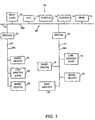
- Three Fieldbus deviceswhich may be, for example, any of the field devices 16-28 of Fig. 1, are illustrated as including resource blocks 48, function blocks 50, 51, or 52 and transducer blocks 53 and 54.
- the function block 50(which may be an input function block) is coupled through the transducer block 53 to a sensor 55, which may be, for example, a temperature sensor, a set point indication sensor, etc.
- the function block 51(which may be an output function block) is coupled through the transducer block 54 to an output device such as a valve 56.
- function block 52(which may be a control function block) has a trend object 57 associated therewith for trending the input parameter of the function block 52.
- Link objects 58define the block parameters of each of the associated blocks and alert objects 59 provide alarms or event notifications for the each of the associated blocks.
- View objects 60are associated with each of the function blocks 50, 51, and 52 and include or group data lists for the function blocks with which they are associated. These lists contain information necessary for each of a set of different defined views.
- the devices of Fig. 2are merely exemplary and other numbers of and types of block objects, link objects, alert objects, trend objects, and view objects may be provided in any field device.
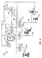
- a block diagram of the process control network 10 depicting the devices 16, 18, and 24 as positioner/valve devices and the devices 20, 22, 26, and 28 as transmittersalso illustrates the function blocks associated with the positioner/valve 16, the transmitter 20, and the bridge 30.
- the positioner/valve 16includes a resource (RSC) block 61, a transducer (XDCR) block 62, and a number of function blocks including an analog output (AO) function block 63, two PID function blocks 64 and 65, and a signal select (SS) function block 69.
- the transmitter 20includes a resource block 61, two transducer blocks 62, and two analog input (AI) function blocks 66 and 67.
- the bridge 30includes a resource block 61 and a PID function block 68.
- the different function blocks of Fig. 3may operate together (by communicating over the bus 34) in a number of control loops and the control loops in which the function blocks of the positioner/valve 16, the transmitter 20, and the bridge 30 are located are identified in Fig. 3 by a loop identification block connected to each of these function blocks.
- the AO function block 63 and the PID function block 64 of the positioner/valve 16 and the AI function block 66 of the transmitter 20are connected within a control loop indicated as LOOP1
- the AI function block 67 of the transmitter 20 and the PID function block 68 of the bridge 30are connected in a control loop indicated as LOOP2.
- the other PID function block 65 of the positioner/valve 16is connected within a control loop indicated as LOOP3.
- control loop LOOP1The interconnected function blocks making up the control loop indicated as LOOP1 in Fig. 3 are illustrated in more detail in the schematic of this control loop depicted in Fig. 4.
- the control loop LOOP1is completely formed by communication links between the AO function block 63 and the PID function block 64 of the positioner/valve 16 and the AI function block 66 of the transmitter 20 (Fig. 3).
- the control loop diagram of Fig. 4illustrates the communication interconnections between these function blocks using lines attaching the process and control inputs and outputs of these functions blocks.
- the output of the AI function block 66which may comprise a process measurement or process parameter signal, is communicatively coupled via the bus segment 34b to the input of the PID function block 64 which has an output comprising a control signal communicatively coupled to an input of the AO function block 63.
- An output of the AO function block 63which comprises a feedback signal indicating, for example, the position of the valve 16, is connected to a control input of the PID function block 64.
- the PID function block 64uses this feedback signal along with the process measurement signal from the AI function block 66 to implement proper control of the AO function block 63.
- control loopsare implemented by other function blocks that are communicatively interconnected in other configurations.
- the Fieldbus protocoluses three general categories of technology identified as a physical layer, a communication "stack," and a user layer.
- the user layerincludes the control and configuration functions provided in the form of blocks (such as function blocks) and objects within any particular process control device or field device.
- the user layeris typically designed in a proprietary manner by the device manufacturer but must be capable of receiving and sending messages according to the standard message format defined by the Fieldbus protocol and of being configured by a user in standard manners.
- the physical layer and the communication stackare necessary to effect communication between different blocks of different field devices in a standardized manner using the two-wire bus 34 and may be modeled by the well-known Open Systems Interconnect (OSI) layered communication model.
- OSIOpen Systems Interconnect
- the physical layerwhich corresponds to OSI layer 1, is embedded in each field device and the bus 34 and operates to convert electromagnetic signals received from the Fieldbus transmission medium (the two-wire bus 34) into messages capable of being used by the communication stack of the field device.
- the physical layermay be thought of as the bus 34 and the electromagnetic signals present on the bus 34 at the inputs and outputs of the field devices.
- the communication stackwhich is present in each Fieldbus device, includes a data link layer, which corresponds to OSI layer 2, a Fieldbus access sublayer, and a Fieldbus message specification layer, which corresponds to OSI layer 6. There is no corresponding structure for OSI layers 3-5 in the Fieldbus protocol. However, the applications of a fieldbus device comprise a layer 7 while a user layer is a layer 8, not defined in the OSI protocol. Each layer in the communication stack is responsible for encoding or decoding a portion of the message or signal that is transmitted on the Fieldbus bus 34.
- each layer of the communication stackadds or removes certain portions of the Fieldbus signal such as preambles, start delimiters, and end delimiters and, in some cases, decodes the stripped portions of the Fieldbus signal to identify where the rest of the signal or message should be sent or if the signal should be discarded because, for example, it contains a message or data for function blocks that are not within the receiving field device.
- the data link layercontrols transmission of messages onto the bus 34 and manages access to the bus 34 according to a deterministic centralized bus scheduler called a link active scheduler, to be described in more detail below.
- the data link layerremoves a preamble from the signals on the transmission medium and may use the received preamble to synchronize the internal clock of the field device with the incoming Fieldbus signal.
- the data link layerconverts messages on the communication stack into physical Fieldbus signals and encodes these signals with clock information to produce a "synchronous serial" signal having a proper preamble for transmission on the two-wire bus 34.
- the data link layerrecognizes special codes within the preamble, such as start delimiters and end delimiters, to identify the beginning and the end of a particular Fieldbus message and may perform a checksum to verify the integrity of the signal or message received from the bus 34.
- the data link layertransmits Fieldbus signals on the bus 34 by adding start and end delimiters to messages on the communication stack and placing these signals on the transmission medium at the appropriate time.
- the Fieldbus message specification layerallows the user layer (i.e., the function blocks, objects, etc. of a field device) to communicate across the bus 34 using a standard set of message formats and describes the communication services, message formats, and protocol behaviors required to build messages to be placed onto the communication stack and to be provided to the user layer. Because the Fieldbus message specification layer supplies standardized communications for the user layer, specific Fieldbus message specification communication services are defined for each type of object described above. For example, the Fieldbus message specification layer includes object dictionary services which allows a user to read an object dictionary of a device. The object dictionary stores object descriptions that describe or identify each of the objects (such as block objects) of a device.
- the Fieldbus message specification layeralso provides context management services which allows a user to read and change communication relationships, known as virtual communication relationships (VCRs) described hereinafter, associated with one or more objects of a device. Still further, the Fieldbus message specification layer provides variable access services, event services, upload and download services, and program invocation services, all of which are well known in the Fieldbus protocol and, therefore, will not be described in more detail herein.
- the Fieldbus access sublayermaps the Fieldbus message specification layer into the data link layer.
- each Fieldbus deviceincludes a management information base (MIB), which is a database that stores VCRs, dynamic variables, statistics, link active scheduler timing schedules, function block execution timing schedules and device tag and address information.
- MIBmanagement information base
- the information within the MIBmay be accessed or changed at any time using standard Fieldbus messages or commands.
- a device descriptionis usually provided with each device to give a user or a host an extended view of the information in the VFD.
- a device descriptionwhich must typically be tokenized to be used by a host, stores information needed for the host to understand the meaning of the data in the VFDs of a device.
- one of the link master devices on each segment of the bus 34(for example, devices 12, 16, and 26) operates as a link active scheduler (LAS) which actively schedules and controls communication on the associated segment of the bus 34.
- the LAS for each segment of the bus 34stores and updates a communication schedule (a link active schedule) containing the times that each function block of each device is scheduled to start periodic communication activity on the bus 34 and the length of time for which this communication activity is to occur.
- communication activities over the bus 34are divided into repeating macrocycles, each of which includes one synchronous communication for each function block active on any particular segment of the bus 34 and one or more asynchronous communications for one or more of the functions blocks or devices active on a segment of the bus 34.
- a devicemay be active, i.e., send data to and receive data from any segment of the bus 34, even if it is physically connected to a different segment of the bus 34, through coordinated operation of the bridges and the LASs on the bus 34.
- each of the function blocks active on a particular segment of the bus 34executes, usually at a different, but precisely scheduled (synchronous) time and, at another precisely scheduled time, publishes its output data on that segment of the bus 34 in response to a compel data command generated by the appropriate LAS.
- each function blockis scheduled to publish its output data shortly after the end of the execution period of the function block.
- the data publishing times of the different function blocksare scheduled serially so that no two function blocks on a particular segment of the bus 34 publish data at the same time.
- each field deviceis allowed, in turn, to transmit alarm data, view data, etc. in an asynchronous manner using token driven communications.
- the execution times and the amount of time necessary to complete execution of each function blockare stored in the management information base (MIB) of the device in which the function block resides while, as noted above, the times for sending the compel data commands to each of the devices on a segment of the bus 34 are stored in the MIB of the LAS device for that segment.
- MIBmanagement information base
- These timesare typically stored as offset times because they identify the times at which a function block is to execute or send data as an offset from the beginning of an "absolute link schedule start time," which is known by all of the devices connected to the bus 34.
- the LASfor example, the LAS 16 of the bus segment 34b, sends a compel data command to each of the devices on the bus segment 34b according to the list of transmit times stored in the link active schedule.
- a function block of a devicepublishes its output data on the bus 34 for a specific amount of time. Because each of the functions blocks is typically scheduled to execute so that execution of that block is completed shortly before the block is scheduled to receive a compel data command, the data published in response to a compel data command should be the most recent output data of the function block.
- the function blockpublishes the output data generated during the last run of the function block and indicates that the published data is old data using a time-stamp.
- the LASmay cause asynchronous communication activities to occur.
- the LASsends a pass token message to a particular field device.
- a field devicereceives a pass token message, that field device has full access to the bus 34 (or a segment thereof) and can send asynchronous messages, such as alarm messages, trend data, operator set point changes, etc. until the messages are complete or until a maximum allotted "token hold time" has expired. Thereafter the field device releases the bus 34 (or any particular segment thereof) and the LAS sends a pass token message to another device.
- This processrepeats until the end of the macrocycle or until the LAS is scheduled to send a compel data command to effect synchronous communication.
- the LASis scheduled to send a compel data command to effect synchronous communication.
- not every devicemay receive a pass token message during each macrocycle.
- Fig. 5illustrates a timing schematic depicting the times at which function blocks on the bus segment 34b of Fig. 1 execute during each macrocycle of the bus segment 34b and the times at which synchronous communications occur during each macrocycle associated with the bus segment 34b.
- timeis indicated on the horizontal axis and activities associated with the different function blocks of the positioner/valve 16 and the transmitter 20 (of Fig. 3) are illustrated on the vertical axis.
- the control loop in which each of the functions blocks operatesis identified in Fig. 5 as a subscript designation.
- AI LOOPIrefers to the AI function block 66 of the transmitter
- PID LOOP1refers to the PID function block 64 of the positioner/valve 16, etc.
- the block execution period of each of the illustrated function blocksis depicted by a cross-hatched box while each scheduled synchronous communication is identified by a vertical bar in Fig. 5.
- the AI LOOP1 function blockexecutes first for the time period specified by the box 70. Then, during the time period indicated by the vertical bar 72, the output of the AI LOOP1 function block is published on the bus segment 34b in response to a compel data command from the LAS for the bus segment 34b.
- the boxes 74, 76, 78, 80, and 81indicate the execution times of the function blocks PID LOOP1 , AI LOOP2 , AO LOOP1 , SS LOOP2 , and PID LOOP3 , respectively (which are different for each of the different blocks), while the vertical bars 82, 84, 86, 88, and 89 indicate the times that the function blocks PID LOOP1 , AI LOOP2 , AO LOOP1 , SS LOOP2 , and PID LOOP3 , respectively, publish data on the bus segment 34b.
- the timing schematic of Fig. 5also illustrates the times available for asynchronous communication activities, which may occur during the execution times of any of the function blocks and during the time at the end of the macrocycle during which no function blocks are executing and when no synchronous communication is taking place on the bus segment 34b.
- different function blockscan be intentionally scheduled to execute at the same time and not all function blocks must publish data on the bus if, for example, no other device subscribes to the data produced by a function block.
- Field devicesare able to publish or transmit data and messages over the bus 34 using one of three virtual communication relationships (VCRs) defined in the Fieldbus access sublayer of the stack of each field device.
- VCRsvirtual communication relationships
- a client/server VCRis used for queued, unscheduled, user initiated, one to one, communications between devices on the bus 34. Such queued messages are sent and received in the order submitted for transmission, according to their priority, without overwriting previous messages.
- a field devicemay use a client/server VCR when it receives a pass token message from an LAS to send a request message to another device on the bus 34.
- the requesteris called the "client” and the device that receives the request is called the "server.”
- the serversends a response when it receives a pass token message from the LAS.
- the client/server VCRis used, for example, to effect operator initiated requests such as set point changes, tuning parameter access and changes, alarm acknowledgements, and device uploads and downloads.
- a report distribution VCRis used for queued, unscheduled, user initiated, one to many communications. For example, when a field device with an event or a trend report receives a pass token from an LAS, that field device sends its message to a "group address" defined in the Fieldbus access sublayer of the communication stack of that device. Devices that are configured to listen on that VCR will receive the report.
- the report distribution VCR typeis typically used by Fieldbus devices to send alarm notifications to operator consoles.
- a publisher/subscriber VCR typeis used for buffered, one to many communications. Buffered communications are ones that store and send only the latest version of the data and, thus, new data completely overwrites previous data. Function block outputs, for example, comprise buffered data.
- a "publisher" field devicepublishes or broadcasts a message using the publisher/subscriber VCR type to all of the "subscriber" field devices on the bus 34 when the publisher device receives a compel data message from the LAS or from a subscriber device.
- the publisher/subscriber relationshipsare predetermined and are defined and stored within the Fieldbus access sublayer of the communication stack of each field device.
- each LASperiodically sends a time distribution message to all of the field devices connected to a segment of the bus 34, which enables the receiving devices to adjust their local application time to be in synchronization with one another. Between these synchronization messages, clock time is independently maintained in each device based on its own internal clock. Clock synchronization allows the field devices to time stamp data throughout the Fieldbus network to indicate, for example, when data was generated.
- each LAS (and other link master device) on each bus segmentstores a "live list," which is a list of all the devices that are connected to that segment of the bus 34, i.e., all of the devices that are properly responding to a pass token message.
- the LAScontinually recognizes new devices added to a bus segment by periodically sending probe node messages to addresses that are not on the live list.
- each LASis required to probe at least one address after it has completed a cycle of sending pass token messages to all of the field devices in the live list. If a field device is present at the probed address and receives the probe node message, the device immediately returns a probe response message.
- the LASUpon receiving a probe response message, the LAS adds the device to the live list and confirms by sending a node activation message to the probed field device.
- a field deviceremains on the live list as long as that field device responds properly to pass token messages. However, an LAS removes a field device from the live list if the field device does not, after three successive tries, either use the token or immediately return the token to the LAS.
- the LASbroadcasts changes in the live list to all the other link master devices on the appropriate segment of the bus 34 to allow each link master device to maintain a current copy of the live list.
- the communication interconnections between the field devices and the function blocks thereofare determined by a user and are implemented within the process control network 10 using a configuration application located in, for example, the host 12.
- the process control network 10operates without any consideration for device or process diagnostics and, therefore, interfaces with the host 12 to perform standard I/O functions, but not diagnostic functions.
- a schematic block diagramillustrates a process control system or network 100 including a network accessible Fieldbus interface (NAFI) 105 that is connected to a remote communications network 106.
- the illustrated control system network 100includes a computer 108, such as a personal computer or workstation, that is connected to a network bus 109 by a controller 110, such as a digital control system controller.
- the computer 108is connected to the controller 110 via a bus 111.
- the control system network 100communicates with the external or remote network 106 by a connection of the network bus 109 at a node 114 and includes a plurality of field devices 116 that are connected to the network bus 109 directly or that are connected to the network bus 109 by a bridge device 118 via a local bus 120.
- Each bridge device 118is typically used to transfer data from a higher frequency bus to a lower frequency bus and vice versa.
- the NAFI device 105is connected between the network bus 109 and a network connection terminal 122 which, in turn, is connected to the remote network 106.
- the remote network 106may have any desired network configuration including, for example, a wide area network (WAN) configuration, a local area network (LAN) configuration, an Ethernet configuration, a modem connection to telephone communications, a radio transmission connection, and the like.
- the NAFI device 105is a computer system such as a personal computer, workstation, or any other system having a special-purpose computer-based communication system or special-purpose computer-based process controller.
- the NAFI device 105includes a software system 124 that serves as a software interface between the control system network 100 and the remote network 106 and that includes a standard process control network communication software stack 126 (such as a Fieldbus communication software stack) and a user software layer 128.
- a standard process control network communication software stack 126such as a Fieldbus communication software stack
- the communication software stack 126is a software interface that controls communication of messages among devices operating in a physical layer of the process control network communication system, i.e., the messages arriving at the software stack 126. As described above, the communication software stack 126 is used by many various application programs for accessing data in field devices and the communication software stack 126 handles communications using low-level protocols including the Fieldbus protocol.
- the user software layer 128performs user interface operations for controlling the NAFI device 105, controls the communication software stack 126 to communication over the process control system 100 to, for example, retrieve specified data from one or more devices within the process control system 100, monitors designated message traffic on the communication software stack 126 including read and write operations and corresponding data, copies the designated message traffic to a file within the device 105, and transmits the file to a remote site though the remote network 106.
- the NAFI device 105interfaces to the network bus 109 via a two-wire terminal connection that is generally used for connecting devices such as the controller 110, the bridge devices 118, or the field devices 116 to the network bus 109 or 120.
- the NAFI device 105can be used to interface with other types of process control systems or networks besides Fieldbus networks including, for example, Profibus networks.
- a high-level schematic block diagramillustrates a computer system 200 suitable for use as the NAFI device 105.
- the computer system 200 of Fig. 7is highly generic and applicable to many configurations with extended functional blocks and applications.
- the NAFI device 105(computer system 200) has a two-wire terminal block 202 that connects to a two-wire media (such as a bus) or that connects to a two-wire media connection terminal of a device.
- the NAFI 105also includes a microprocessor 204, a communications interface 206, a media access unit 208, and a plurality of storage units such as a random access memory (RAM) 210, a read only memory (ROM) 212 and a nonvolatile random access memory (NVRAM) 214.
- RAMrandom access memory
- ROMread only memory
- NVRAMnonvolatile random access memory
- the communications interface 206is a circuit that performs serial to parallel protocol conversion and parallel to serial protocol conversion and that adds framing information to data packets according to the definition of the communication protocol of the process control system in which the device 105 is being used. As illustrated in Fig. 7, the interface 206 forms an interface between the microprocessor 204 and the media access unit 208 which may be used to convert, for example, a two-wire media communication signal to a digital representation of the communication signal.
- the media access unit 208receives power from the two-wire media or from a conventional power source and supplies this power to other circuits in the NAFI device 105.
- the media access unit 208also 208 performs wave-shaping and signaling on the two-wire media or bus (such as the bus 109 of Fig. 6).
- the storage devices 110, 112 and 114supply memory to the NAFI device 105 and interface with the microprocessor 204.
- the RAM 210may be a 128 Kbyte storage unit
- the ROM 212may be a 256 Kbyte storage unit
- the NVRAM 214may be a 32 Kbyte nonvolatile storage unit.
- the NAFI device 105executes instructions in the microprocessor 204 from a program code stored in one or more of the storage devices 210, 212 or 214 to perform communication interfacing.
- the NAFI device 105may be implemented in virtually any computer system in the control system network 100 including computer systems in the controller 110, any of the bridge devices 118, and/or the field devices 116 as well as in a stand-alone computer system.
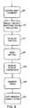
- a flow chartillustrates operations performed by the NAFI software system or device 105.
- the NAFI software system 105receives user commands from a user including: (1) commands by a local user initiating data collection and defining the particular traffic on the communication software stack 126 to be monitored, (2) commands by a local user for initializing a NAFI transfer file, (3) commands by a local user or a remote user at a remote site for sending a NAFI transfer file to a remote device, (4) commands and corresponding data received from a remote user at a remote source, and (5) commands received from the remote user at the remote site requesting the transmission of a designated NAFI transfer file.
- the receive user command step 222is typically interrupt-driven and asynchronous.
- a select traffic and start data collection step 224sets various conditional variables or statements that define the message traffic to be monitored and requests that the communication software stack 126 transfer data to the user software layer 128 corresponding to the requested data.
- an initialize NAFI file step 226is performed.
- datais transferred via the communication software stack 126 using various application programs.
- the user software layer 128monitors any designated data or all data, if desired, no matter what application program generates the data transfer.
- One example of an application program using the communication software stack 126 for communications with field devicesis ValveLink software that communicates with a control valve via the control system network 100.
- ValveLink softwareis manufactured by and available from Fisher Control International Inc. in conjunction with its Valvelink products.
- the NAFI software system 105may monitor data with respect to any dialog system that reads and writes via the communication software stack 126 and the user software layer 128 accesses any data on the network bus 109 for remote communication.
- a send NAFI file step 228transmits the messages and data in the NAFI file to a remote site which is addressed in accordance with, for example, an argument of the transmit command.
- the messages and data that are sent to the remote siteinclude requests and replies that are handled by the communication software stack 126 during control and data transmission operations of the control system network 100 in accordance with the communication protocol of the control system network 100, such as the Fieldbus protocol.
- the amount of information transferred over the remote network 106is very small compared to data in other forms, such as the transmission of an entire computer screen or the transmission of data burdened by handling information added during passage through numerous network nodes.
- the NAFI device 105advantageously reduces the overhead expenditure in time and data transfer size for communicating field device data over a network.
- the NAFI transfer fileis sent over the remote network 106 to the defined remote site, which loads the file so that messages and data defined by the control system network protocol are available for analysis and display at the remote site which, in turn, allows the remote user to run applications corresponding to applications executed by the local user to recreate operations and test conditions during remote diagnosis and interrogations and investigations of device status and problems.
- the remote usermust have appropriate software that decodes or deciphers the meaning of the data sent from the NAFI device.
- data communication using the NAFI device 105advantageously permits remote diagnostic testing, maintenance and trouble-shooting.
- messages and informationare advantageously transmitted very rapidly using the NAFI device 105 because the data is transmitted asynchronously and independently between the local user and the remote user to thereby avoid synchronization problems.
- the data and messagesare transmitted asynchronously with respect to the collection of data so that data collection and data transmission are advantageously disconnected, preventing a bottleneck condition in which data collection is stalled when a network communication connection is unavailable and communication is stalled while waiting for data to be collected.
- a receive remote transmission step 230receives the command and data and initiates any commanded operations on the local control system network 100 using standard communication devices, such as a software communication stack associated with the communication protocol used by the control system network 100.
- a monitor stack step 232the NAFI software system 124 monitors the message traffic on the communication software stack 126 that is designated by the user.
- the trafficis made available to the user software layer 128 in response to the request that the communication software stack 126 transfer data to the user software layer 128 made in select traffic and start data collection step 224.
- the message trafficincludes the requests and replies that are communicated by the communication software stack 126 during process control operations.
- a copy message traffic to a file step 234copies read and write requests and data to a NAFI file.
- the NAFI filemay be one file of a plurality of NAFI files that are designated for storing specific information, such as information regarding a specific field device or valve and these files may be stored in any of the memory units 210 or 214 of the NAFI device 105.
- the NAFI device 105is a simple system that is implemented as a computer system with NAFI software system 124 advantageously avoiding the use of expensive and complicated high-speed communication gear including fiber-optic links and converters.
- a schematic block diagramshows several possible implementations of a network accessible Fieldbus interface for communicating between one or more of a plurality of process control elements and remote elements.
- the NAFI device 105is illustrated in accordance with the NAFI connection shown in Fig. 6.
- a NAFI device or interface 302is illustrated as being incorporated into the controller 110.
- the NAFI device 302may be connected to the remote network 106 directly or by a connection through a further NAFI device 304, illustrating a NAFI-NAFI connection.
- the computer 108may incorporate a NAFI device 306 that is connected to the remote network 106 directly or by a connection to the NAFI device 304.
- the network accessible interface of the present inventionmay-also be incorporated into other devices including any of the bridge devices 118 and/or field devices 116, which may be fluid control valves or any other types of field device such as sensors, transmitters, wall-mounted panels, etc.
- a NAFI device 308 incorporated into one of the bridges 118 and a NAFI device 310 incorporated into one of the field devices 116are both shown connected directly to the remote network 106 but may, if desired, be indirectly connected via a further NAFI device.
- the network accessible interface of the present inventionmay perform other functions as desired and may perform any combination of functions in any desired order to effect communications between a process control network and a remote network.
- the network accessible interface described hereinis preferably implemented in software stored in, for example, a process control device, a controller or a personal computer, it may alternatively or additionally be implemented in hardware, firmware, etc., as desired. That is, the processor described herein may include any hardwired logic arrays or other hardware devices designed to implement the functionality described herein. If implemented in software, the network accessible interface of the present invention may be stored in any computer readable memory such as on a magnetic disk, a laser disk, or other storage medium, in a RAM or ROM of a computer, etc.
- this softwaremay be delivered to a user or a device via any known or desired delivery method including, for example, over a communication channel such as a telephone line, the internet, etc.
- a communication channelsuch as a telephone line, the internet, etc.
- the network accessible interface deviceis described herein as implementing or using a communication software stack conforming to the Open Systems Interconnect (OSI) layered communication model to perform communication functions in a process control system, it will be understood that this communication software stack may be implemented by any software that performs standard communication functions according to a communication protocol, whether or not these functions are implemented in a stack format such as that described by the OSI model.
- OSIOpen Systems Interconnect
Landscapes
- Engineering & Computer Science (AREA)
- Physics & Mathematics (AREA)
- General Physics & Mathematics (AREA)
- Automation & Control Theory (AREA)
- General Engineering & Computer Science (AREA)
- Manufacturing & Machinery (AREA)
- Quality & Reliability (AREA)
- Programmable Controllers (AREA)
- Testing And Monitoring For Control Systems (AREA)
- Small-Scale Networks (AREA)
- Communication Control (AREA)
Description
Claims (17)
- An interface (105) between a communications network(106) that uses a first communication protocol and aprocess control system (100) having a bus (109) thatuses a second communication protocol, comprising:a processor (204);a storage device (210) coupled to the processor (204);a software system (124) for executing on the processor(204) including; anda communication software stack (126) adapted to becommunicatively coupled to the bus (109) and to operatein the process control system (100) using the secondcommunication protocol,a monitoring routine (232) adapted to monitor messagetraffic on the communication software stack (126),a copying routine (234) adapted to copy the messagetraffic to the storage device (210), anda media interface routine (208) adapted to enable remoteaccess to the storage device (210) via thecommunications network (106) using the firstcommunication protocol.
- The interface (105) of Claim 1, wherein thecommunication software stack (126) includes a controlroutine that controls communications in the process control system (100) using a two-wire, two-way, loop-powereddigital communication protocol.
- The interface (105) of Claim 1, wherein thecommunication software stack (126) includes a controlroutine that controls communications in the processcontrol system (100) using a Fieldbus protocol.
- The interface (105) of Claim 1, which is implemented byan article of manufacture for executing in a processor(204), the processor (204) being coupled to a storageand including a communication software stack (126)operating in the process control system (100).
- The interface (105) of claim 1, adapted to be coupledbetween a remote communications network (106) and aprocess control system (100) that uses a communicationprotocol to implement communications between deviceswithin the process control system (100), the interface(105) further comprising:a data storage device (210, 212, 214);a communication device (105) coupled between the datastorage device and the process control system (100), thecommunication device (105) adapted to communicate on theprocess control system (100) using the communicationprotocol and to retrieve data from the process controlsystem (100);a controller (110) coupled to the data storage device,the communication device (105) and the remotecommunications network (106) that stores the retrieveddata in the storage device, that communicates the datawithin the storage device over the remote communications network (106) and that controls operation of thecommunication device (105).
- The interface (105) of Claim 5, wherein thecommunication device (105) includes a communicationsoftware stack (126) having a communication routine thatcommunicates in the process control system (100) using atwo-wire, two-way, loop-powered digital communicationprotocol.
- The interface (105) of Claim 5, wherein thecommunication device includes a communication softwarestack (126) that implements communications, within theprocess control system (100).
- The interface (105) of Claim 7, wherein thecommunication software stack (126) is configuredaccording to the Open Systems Interconnect layeredcommunication model to implement communications withinthe process control system (100).
- The interface (105) of Claim 5, wherein thecommunication protocol is a Fieldbus communicationprotocol.
- The interface (105) of Claim 5, wherein thecommunication device (105) includes a processor (204)that implements a first routine to request data from adevice within the process control system using thecommunication protocol, a second routine to receive therequested data from the process control system (100) anda third routine to deliver the received data to thecontroller (110).
- The interface (105) of Claim 5, wherein thecommunication device (105) includes a processor (204) that implements a first routine to monitor communicationdata within the process control system (100), a secondroutine to recognize specific communication dataspecified by the controller (110) and a third routine todeliver the specific communication data to thecontroller (110).
- The interface (105) of Claim 5, wherein the controller(110) is adapted to receive a message specifyingspecific data within the process control system (100),is adapted to control the communication device (105) toretrieve the specific data from the process controlsystem (100) and is adapted to store the specific datain the storage device (210) in response to the message.
- The interface (105) of Claim 5, wherein the controller(110) is adapted to receive a message requesting thetransfer of specific data stored in the storage device(210) over the remote communications network (106) andincludes a routine that transfers the specific data fromthe storage device (210) over the remote communicationsnetwork (106) in response to the message.
- The interface (105) of Claim 13, wherein the controller(110) is adapted to receive the message from the remotecommunications network (106).
- The interface (105) of Claim 13, wherein the controller(110) is adapted to receive the message from the processcontrol system (100).
- The interface (105) of Claim 5, wherein the controller(110) stores the data within the storage device (210)asynchronously with respect to the controller (110)communicating the data stored in the storage device(210) over the remote communications network (106).
- The interface (105) of Claim 5, wherein the remotecommunications network (106) is a local area network ora wide area network.
Applications Claiming Priority (3)
| Application Number | Priority Date | Filing Date | Title |
|---|---|---|---|
| US726264 | 1985-04-22 | ||
| US72626496A | 1996-10-04 | 1996-10-04 | |
| PCT/US1997/017712WO1998014852A1 (en) | 1996-10-04 | 1997-10-02 | A network accessible interface for a process control network |
Publications (3)
| Publication Number | Publication Date |
|---|---|
| EP0928443A1 EP0928443A1 (en) | 1999-07-14 |
| EP0928443B1true EP0928443B1 (en) | 2002-01-30 |
| EP0928443B2 EP0928443B2 (en) | 2006-12-13 |
Family
ID=24917873
Family Applications (1)
| Application Number | Title | Priority Date | Filing Date |
|---|---|---|---|
| EP97945427AExpired - LifetimeEP0928443B2 (en) | 1996-10-04 | 1997-10-02 | A network accessible interface for a process control network |
Country Status (9)
| Country | Link |
|---|---|
| US (1) | US6192281B1 (en) |
| EP (1) | EP0928443B2 (en) |
| JP (1) | JP3993243B2 (en) |
| CN (1) | CN1178113C (en) |
| AU (1) | AU4663497A (en) |
| BR (1) | BR9712194A (en) |
| CA (1) | CA2267502C (en) |
| DE (1) | DE69710201T3 (en) |
| WO (1) | WO1998014852A1 (en) |
Families Citing this family (163)
| Publication number | Priority date | Publication date | Assignee | Title |
|---|---|---|---|---|
| JP3754456B2 (en)* | 1996-02-22 | 2006-03-15 | クヴァセル コンスルタント アクティエ ボラーグ | Apparatus in a control and / or management system operating with CAN protocol |
| US6539267B1 (en) | 1996-03-28 | 2003-03-25 | Rosemount Inc. | Device in a process system for determining statistical parameter |
| US7949495B2 (en)* | 1996-03-28 | 2011-05-24 | Rosemount, Inc. | Process variable transmitter with diagnostics |
| US8290721B2 (en)* | 1996-03-28 | 2012-10-16 | Rosemount Inc. | Flow measurement diagnostics |
| US7623932B2 (en) | 1996-03-28 | 2009-11-24 | Fisher-Rosemount Systems, Inc. | Rule set for root cause diagnostics |
| US7254518B2 (en) | 1996-03-28 | 2007-08-07 | Rosemount Inc. | Pressure transmitter with diagnostics |
| US6654697B1 (en) | 1996-03-28 | 2003-11-25 | Rosemount Inc. | Flow measurement with diagnostics |
| US7630861B2 (en)* | 1996-03-28 | 2009-12-08 | Rosemount Inc. | Dedicated process diagnostic device |
| US6907383B2 (en) | 1996-03-28 | 2005-06-14 | Rosemount Inc. | Flow diagnostic system |
| US7085610B2 (en) | 1996-03-28 | 2006-08-01 | Fisher-Rosemount Systems, Inc. | Root cause diagnostics |
| US6017143A (en) | 1996-03-28 | 2000-01-25 | Rosemount Inc. | Device in a process system for detecting events |
| EP0825506B1 (en)* | 1996-08-20 | 2013-03-06 | Invensys Systems, Inc. | Methods and apparatus for remote process control |
| US6449574B1 (en) | 1996-11-07 | 2002-09-10 | Micro Motion, Inc. | Resistance based process control device diagnostics |
| US6519546B1 (en) | 1996-11-07 | 2003-02-11 | Rosemount Inc. | Auto correcting temperature transmitter with resistance based sensor |
| US6434504B1 (en) | 1996-11-07 | 2002-08-13 | Rosemount Inc. | Resistance based process control device diagnostics |
| US6754601B1 (en) | 1996-11-07 | 2004-06-22 | Rosemount Inc. | Diagnostics for resistive elements of process devices |
| JP3340358B2 (en)* | 1997-09-08 | 2002-11-05 | 株式会社東芝 | Programmable controller |
| AU9795598A (en)* | 1997-10-13 | 1999-05-03 | Rosemount Inc. | Communication technique for field devices in industrial processes |
| FI114745B (en)* | 1998-06-01 | 2004-12-15 | Metso Automation Oy | Control systems for field devices |
| US6285966B1 (en) | 1998-06-25 | 2001-09-04 | Fisher Controls International, Inc. | Function block apparatus for viewing data in a process control system |
| US6571273B1 (en)* | 1998-07-13 | 2003-05-27 | Yokogawa Electric Corporation | Process control system |
| US6611775B1 (en) | 1998-12-10 | 2003-08-26 | Rosemount Inc. | Electrode leakage diagnostics in a magnetic flow meter |
| US6615149B1 (en) | 1998-12-10 | 2003-09-02 | Rosemount Inc. | Spectral diagnostics in a magnetic flow meter |
| US7206646B2 (en)* | 1999-02-22 | 2007-04-17 | Fisher-Rosemount Systems, Inc. | Method and apparatus for performing a function in a plant using process performance monitoring with process equipment monitoring and control |
| US6774786B1 (en)* | 2000-11-07 | 2004-08-10 | Fisher-Rosemount Systems, Inc. | Integrated alarm display in a process control network |
| US6477573B1 (en)* | 1999-04-09 | 2002-11-05 | Sony Corporation | System and method for performing a hierarchical remote query in an electronic network |
| US7257523B1 (en)* | 1999-05-06 | 2007-08-14 | Fisher-Rosemount Systems, Inc. | Integrated distributed process control system functionality on a single computer |
| AU5273100A (en)* | 1999-05-17 | 2000-12-05 | Foxboro Company, The | Methods and apparatus for control configuration with versioning, security, composite blocks, edit selection, object swapping, formulaic values and other aspects |
| US7089530B1 (en)* | 1999-05-17 | 2006-08-08 | Invensys Systems, Inc. | Process control configuration system with connection validation and configuration |
| US6788980B1 (en)* | 1999-06-11 | 2004-09-07 | Invensys Systems, Inc. | Methods and apparatus for control using control devices that provide a virtual machine environment and that communicate via an IP network |
| US6356191B1 (en) | 1999-06-17 | 2002-03-12 | Rosemount Inc. | Error compensation for a process fluid temperature transmitter |
| US7010459B2 (en)* | 1999-06-25 | 2006-03-07 | Rosemount Inc. | Process device diagnostics using process variable sensor signal |
| US6473710B1 (en) | 1999-07-01 | 2002-10-29 | Rosemount Inc. | Low power two-wire self validating temperature transmitter |
| US6505517B1 (en) | 1999-07-23 | 2003-01-14 | Rosemount Inc. | High accuracy signal processing for magnetic flowmeter |
| US6564056B1 (en)* | 1999-08-03 | 2003-05-13 | Avaya Technology Corp. | Intelligent device controller |
| US6701274B1 (en) | 1999-08-27 | 2004-03-02 | Rosemount Inc. | Prediction of error magnitude in a pressure transmitter |
| WO2001020416A2 (en)* | 1999-09-14 | 2001-03-22 | Siemens Aktiengesellschaft | Serial data transmission via a bus system |
| US6574522B1 (en)* | 1999-09-24 | 2003-06-03 | General Electric Company | System and method of collecting statistically analyzing and graphically displaying quality control data for a manufacturing process |
| US6556145B1 (en) | 1999-09-24 | 2003-04-29 | Rosemount Inc. | Two-wire fluid temperature transmitter with thermocouple diagnostics |
| US6654796B1 (en)* | 1999-10-07 | 2003-11-25 | Cisco Technology, Inc. | System for managing cluster of network switches using IP address for commander switch and redirecting a managing request via forwarding an HTTP connection to an expansion switch |
| EP1222402A1 (en)* | 1999-10-20 | 2002-07-17 | Parker Hannifin Plc | Fluid control system |
| FR2804218B1 (en)* | 2000-01-26 | 2002-03-29 | Schneider Automation | PROGRAMMABLE CONTROLLER WITH COMMUNICATION FUNCTIONS IN A CLIENT-SERVER ARCHITECTURE |
| US6574515B1 (en)* | 2000-05-12 | 2003-06-03 | Rosemount Inc. | Two-wire field-mounted process device |
| US7844365B2 (en)* | 2000-05-12 | 2010-11-30 | Rosemount Inc. | Field-mounted process device |
| US7228186B2 (en)* | 2000-05-12 | 2007-06-05 | Rosemount Inc. | Field-mounted process device with programmable digital/analog interface |
| DE10030845B4 (en)* | 2000-06-23 | 2008-11-20 | Abb Ag | Fieldbus connection system for actuators or sensors |
| US6735484B1 (en) | 2000-09-20 | 2004-05-11 | Fargo Electronics, Inc. | Printer with a process diagnostics system for detecting events |
| EP1193578A1 (en)* | 2000-09-21 | 2002-04-03 | Abb Research Ltd. | Measurement event representation of a control system |
| US6640140B1 (en)* | 2000-10-10 | 2003-10-28 | Schneider Automation Inc. | PLC executive with integrated web server |
| US7113085B2 (en)* | 2000-11-07 | 2006-09-26 | Fisher-Rosemount Systems, Inc. | Enhanced device alarms in a process control system |
| US20040063710A1 (en)* | 2000-11-22 | 2004-04-01 | Tomiya Mano | Ophthalmological preparations |
| US6970003B2 (en) | 2001-03-05 | 2005-11-29 | Rosemount Inc. | Electronics board life prediction of microprocessor-based transmitters |
| US7462103B2 (en)* | 2001-03-22 | 2008-12-09 | Igt | Gaming system for individual control of access to many devices with few wires |
| US7398302B2 (en)* | 2001-03-30 | 2008-07-08 | Hitachi, Ltd. | Remote copy with path selection and prioritization |
| US6728849B2 (en) | 2001-12-14 | 2004-04-27 | Hitachi, Ltd. | Remote storage system and method |
| US6629059B2 (en) | 2001-05-14 | 2003-09-30 | Fisher-Rosemount Systems, Inc. | Hand held diagnostic and communication device with automatic bus detection |
| US6859755B2 (en) | 2001-05-14 | 2005-02-22 | Rosemount Inc. | Diagnostics for industrial process control and measurement systems |
| US7051143B2 (en)* | 2001-06-25 | 2006-05-23 | Schneider Automation Inc. | Method, system and program for the transmission of modbus messages between networks |
| US6959356B2 (en)* | 2001-07-30 | 2005-10-25 | Fisher-Rosemount Systems, Inc. | Multi-protocol field device and communication method |
| US6772036B2 (en) | 2001-08-30 | 2004-08-03 | Fisher-Rosemount Systems, Inc. | Control system using process model |
| US7430453B2 (en)* | 2001-11-08 | 2008-09-30 | Eim Company, Inc. | Remote replication of local actuator mode selection |
| US7426452B2 (en)* | 2001-12-06 | 2008-09-16 | Fisher-Rosemount Systems. Inc. | Dual protocol handheld field maintenance tool with radio-frequency communication |
| US20030204373A1 (en)* | 2001-12-06 | 2003-10-30 | Fisher-Rosemount Systems, Inc. | Wireless communication method between handheld field maintenance tools |
| ATE308775T1 (en) | 2001-12-06 | 2005-11-15 | Fisher Rosemount Systems Inc | INTRINSICALLY SAFE FIELD EQUIPMENT MAINTENANCE TOOL |
| US20030229472A1 (en)* | 2001-12-06 | 2003-12-11 | Kantzes Christopher P. | Field maintenance tool with improved device description communication and storage |
| US6973508B2 (en)* | 2002-02-12 | 2005-12-06 | Fisher-Rosemount Systems, Inc. | Highly versatile process control system controller |
| US7027952B2 (en)* | 2002-03-12 | 2006-04-11 | Fisher-Rosemount Systems, Inc. | Data transmission method for a multi-protocol handheld field maintenance tool |
| US7039744B2 (en)* | 2002-03-12 | 2006-05-02 | Fisher-Rosemount Systems, Inc. | Movable lead access member for handheld field maintenance tool |
| US7054337B2 (en)* | 2002-03-15 | 2006-05-30 | Fisher Controls International Llc. | Method and apparatus for optimizing communications in a multiplexer network |
| US20030174068A1 (en)* | 2002-03-15 | 2003-09-18 | Dobos Jeffrey A. | Apparatus for calibrating a digital field sensor |
| FI113121B (en)* | 2002-05-30 | 2004-02-27 | Metso Automation Oy | Systems, data communication networks and a method for transmitting information |
| US20030234047A1 (en)* | 2002-06-24 | 2003-12-25 | Ali Shajii | Apparatus and method for dual processor mass flow controller |
| US6810308B2 (en) | 2002-06-24 | 2004-10-26 | Mks Instruments, Inc. | Apparatus and method for mass flow controller with network access to diagnostics |
| US6712084B2 (en) | 2002-06-24 | 2004-03-30 | Mks Instruments, Inc. | Apparatus and method for pressure fluctuation insensitive mass flow control |
| US6868862B2 (en)* | 2002-06-24 | 2005-03-22 | Mks Instruments, Inc. | Apparatus and method for mass flow controller with a plurality of closed loop control code sets |
| US20030234045A1 (en)* | 2002-06-24 | 2003-12-25 | Ali Shajii | Apparatus and method for mass flow controller with on-line diagnostics |
| US6948508B2 (en) | 2002-06-24 | 2005-09-27 | Mks Instruments, Inc. | Apparatus and method for self-calibration of mass flow controller |
| US7552015B2 (en)* | 2002-06-24 | 2009-06-23 | Mks Instruments, Inc. | Apparatus and method for displaying mass flow controller pressure |
| US7004191B2 (en)* | 2002-06-24 | 2006-02-28 | Mks Instruments, Inc. | Apparatus and method for mass flow controller with embedded web server |
| US7136767B2 (en)* | 2002-06-24 | 2006-11-14 | Mks Instruments, Inc. | Apparatus and method for calibration of mass flow controller |
| US7809473B2 (en) | 2002-06-24 | 2010-10-05 | Mks Instruments, Inc. | Apparatus and method for pressure fluctuation insensitive mass flow control |
| GB2419676B8 (en)* | 2002-06-24 | 2008-09-03 | Mks Instr Inc | Mass flow calibrator |
| US7185045B2 (en)* | 2002-07-15 | 2007-02-27 | Sixnet, Llc | Ethernet interface device for reporting status via common industrial protocols |
| EP1892885B1 (en) | 2002-07-18 | 2010-11-03 | VEGA Grieshaber KG | Bus station with an integrated bus monitor function |
| DE50308807D1 (en) | 2002-07-18 | 2008-01-24 | Grieshaber Vega Kg | BUS STATION WITH INTEGRATED BUS MONITOR FUNCTION |
| US7392100B1 (en)* | 2002-08-15 | 2008-06-24 | Rockwell Automation Technologies, Inc. | System and methodology that facilitate factory automation services in a distributed industrial automation environment |
| US7363380B2 (en)* | 2002-10-29 | 2008-04-22 | Honeywell International Inc. | Method for optimizing a link schedule |
| US10261506B2 (en)* | 2002-12-05 | 2019-04-16 | Fisher-Rosemount Systems, Inc. | Method of adding software to a field maintenance tool |
| US20040158553A1 (en)* | 2003-02-07 | 2004-08-12 | Ise Research Corporation | Method of using a smart device with a separate generic interface application |
| DE10307650A1 (en)* | 2003-02-21 | 2004-09-02 | Endress + Hauser Gmbh + Co. Kg | Process for transferring data via a fieldbus in process automation technology |
| WO2004081686A2 (en)* | 2003-03-06 | 2004-09-23 | Fisher-Rosemount Systems, Inc. | Heat flow regulating cover for an electrical storage cell |
| US7512521B2 (en)* | 2003-04-30 | 2009-03-31 | Fisher-Rosemount Systems, Inc. | Intrinsically safe field maintenance tool with power islands |
| US7054695B2 (en) | 2003-05-15 | 2006-05-30 | Fisher-Rosemount Systems, Inc. | Field maintenance tool with enhanced scripts |
| US7526802B2 (en)* | 2003-05-16 | 2009-04-28 | Fisher-Rosemount Systems, Inc. | Memory authentication for intrinsically safe field maintenance tools |
| US7036386B2 (en)* | 2003-05-16 | 2006-05-02 | Fisher-Rosemount Systems, Inc. | Multipurpose utility mounting assembly for handheld field maintenance tool |
| US6925419B2 (en)* | 2003-05-16 | 2005-08-02 | Fisher-Rosemount Systems, Inc. | Intrinsically safe field maintenance tool with removable battery pack |
| US8874402B2 (en)* | 2003-05-16 | 2014-10-28 | Fisher-Rosemount Systems, Inc. | Physical memory handling for handheld field maintenance tools |
| US7199784B2 (en)* | 2003-05-16 | 2007-04-03 | Fisher Rosemount Systems, Inc. | One-handed operation of a handheld field maintenance tool |
| DE10328906A1 (en)* | 2003-06-26 | 2005-01-13 | Endress + Hauser Process Solutions Ag | field bus |
| EP1646864B1 (en)* | 2003-07-18 | 2018-11-07 | Rosemount Inc. | Process diagnostics |
| US7018800B2 (en)* | 2003-08-07 | 2006-03-28 | Rosemount Inc. | Process device with quiescent current diagnostics |
| US7627441B2 (en)* | 2003-09-30 | 2009-12-01 | Rosemount Inc. | Process device with vibration based diagnostics |
| US7016741B2 (en)* | 2003-10-14 | 2006-03-21 | Rosemount Inc. | Process control loop signal converter |
| US7523667B2 (en)* | 2003-12-23 | 2009-04-28 | Rosemount Inc. | Diagnostics of impulse piping in an industrial process |
| US7222199B2 (en)* | 2004-03-31 | 2007-05-22 | Intel Corporation | Circuit and method for transferring low frequency signals via high frequency interface |
| US6920799B1 (en) | 2004-04-15 | 2005-07-26 | Rosemount Inc. | Magnetic flow meter with reference electrode |
| US7046180B2 (en) | 2004-04-21 | 2006-05-16 | Rosemount Inc. | Analog-to-digital converter with range error detection |
| US7680970B2 (en)* | 2004-10-22 | 2010-03-16 | Fisher-Rosemount Systems, Inc. | Method and system for batch process arbitration in a process control system |
| US20060224711A1 (en)* | 2005-03-29 | 2006-10-05 | Eaton Corporation | Self-learning server communicating values from a plurality of communicating devices of one communication network to a client of another communication network |
| US9201420B2 (en) | 2005-04-08 | 2015-12-01 | Rosemount, Inc. | Method and apparatus for performing a function in a process plant using monitoring data with criticality evaluation data |
| US8005647B2 (en) | 2005-04-08 | 2011-08-23 | Rosemount, Inc. | Method and apparatus for monitoring and performing corrective measures in a process plant using monitoring data with corrective measures data |
| US8112565B2 (en)* | 2005-06-08 | 2012-02-07 | Fisher-Rosemount Systems, Inc. | Multi-protocol field device interface with automatic bus detection |
| US7835295B2 (en)* | 2005-07-19 | 2010-11-16 | Rosemount Inc. | Interface module with power over Ethernet function |
| US9634858B2 (en)* | 2005-07-20 | 2017-04-25 | Rosemount Inc. | Field device with power over Ethernet |
| US20070068225A1 (en)* | 2005-09-29 | 2007-03-29 | Brown Gregory C | Leak detector for process valve |
| JP4873220B2 (en)* | 2005-11-07 | 2012-02-08 | 横河電機株式会社 | Field communication system |
| US8700772B2 (en)* | 2006-05-03 | 2014-04-15 | Cloud Systems, Inc. | System and method for automating the management, routing, and control of multiple devices and inter-device connections |
| US8909779B2 (en) | 2006-05-03 | 2014-12-09 | Cloud Systems, Inc. | System and method for control and monitoring of multiple devices and inter-device connections |
| JP5016670B2 (en)* | 2006-05-03 | 2012-09-05 | クラウド システムズ, インコーポレイテッド | System and method for managing, routing, and controlling connection between devices |
| US7813817B2 (en)* | 2006-05-19 | 2010-10-12 | Westinghouse Electric Co Llc | Computerized procedures system |
| US9411769B2 (en) | 2006-09-19 | 2016-08-09 | Fisher-Rosemount Systems, Inc. | Apparatus and methods to communicatively couple field devices to controllers in a process control system |
| US8332567B2 (en) | 2006-09-19 | 2012-12-11 | Fisher-Rosemount Systems, Inc. | Apparatus and methods to communicatively couple field devices to controllers in a process control system |
| US8774204B2 (en)* | 2006-09-25 | 2014-07-08 | Fisher-Rosemount Systems, Inc. | Handheld field maintenance bus monitor |
| US7953501B2 (en) | 2006-09-25 | 2011-05-31 | Fisher-Rosemount Systems, Inc. | Industrial process control loop monitor |
| US7750642B2 (en) | 2006-09-29 | 2010-07-06 | Rosemount Inc. | Magnetic flowmeter with verification |
| US8005553B2 (en)* | 2006-09-29 | 2011-08-23 | Fisher-Rosemount Systems, Inc. | Automatic configuration of synchronous block execution for control modules run in fieldbus networks |
| US7321846B1 (en) | 2006-10-05 | 2008-01-22 | Rosemount Inc. | Two-wire process control loop diagnostics |
| US20080134201A1 (en)* | 2006-12-01 | 2008-06-05 | Von Helmolt Hans-Ulrich A | Distributed process control and excecution |
| US20080143491A1 (en)* | 2006-12-13 | 2008-06-19 | Deaver Brian J | Power Line Communication Interface Device and Method |
| CN102385346B (en)* | 2007-06-13 | 2015-07-29 | 费希尔-罗斯蒙德系统公司 | The improvement function of handheld field maintenance tools |
| US8898036B2 (en)* | 2007-08-06 | 2014-11-25 | Rosemount Inc. | Process variable transmitter with acceleration sensor |
| US7590511B2 (en)* | 2007-09-25 | 2009-09-15 | Rosemount Inc. | Field device for digital process control loop diagnostics |
| DE102007045926A1 (en)* | 2007-09-26 | 2009-04-02 | Robert Bosch Gmbh | Interface between a production management system and an automation system |
| CN101424941B (en)* | 2007-10-31 | 2011-05-25 | 北京北方微电子基地设备工艺研究中心有限责任公司 | Control implementing method and system |
| US8255065B2 (en)* | 2008-05-05 | 2012-08-28 | Siemens Aktiengesellschaft | Mobile function block for a PLC based distributed control system |
| EP2131256B1 (en)* | 2008-06-04 | 2012-05-30 | VEGA Grieshaber KG | Determining datagram lengths |
| CN104407518B (en) | 2008-06-20 | 2017-05-31 | 因文西斯系统公司 | The system and method interacted to the reality and Simulation Facility for process control |
| US9083548B2 (en)* | 2008-09-23 | 2015-07-14 | Fisher-Rosemount Systems, Inc. | Apparatus and methods to communicatively couple field devices to controllers in a process control system |
| US8374094B2 (en)* | 2008-12-11 | 2013-02-12 | Fisher-Rosemount Systems, Inc | Methods and systems to verify a communication path between a field device and a process controller in a process control system |
| US8977851B2 (en)* | 2009-01-21 | 2015-03-10 | Fisher-Rosemount Systems, Inc. | Removable security modules and related methods |
| GB0903836D0 (en) | 2009-03-05 | 2009-04-22 | Oxford Instr Plasma Technology | Interface module and controller network |
| US7921734B2 (en)* | 2009-05-12 | 2011-04-12 | Rosemount Inc. | System to detect poor process ground connections |
| US8127060B2 (en)* | 2009-05-29 | 2012-02-28 | Invensys Systems, Inc | Methods and apparatus for control configuration with control objects that are fieldbus protocol-aware |
| US8463964B2 (en)* | 2009-05-29 | 2013-06-11 | Invensys Systems, Inc. | Methods and apparatus for control configuration with enhanced change-tracking |
| US8311778B2 (en)* | 2009-09-22 | 2012-11-13 | Rosemount Inc. | Industrial process control transmitter with multiple sensors |
| US8287270B2 (en) | 2009-09-30 | 2012-10-16 | Printpack Illinois Inc. | Methods and systems for thermoforming with billets |
| US9207670B2 (en) | 2011-03-21 | 2015-12-08 | Rosemount Inc. | Degrading sensor detection implemented within a transmitter |
| US20140143607A1 (en)* | 2012-02-10 | 2014-05-22 | Phoenix Contact Development & Manufacturing, Inc. | Dedicated Network Diagnostics Module for a Process Network |
| US9052240B2 (en) | 2012-06-29 | 2015-06-09 | Rosemount Inc. | Industrial process temperature transmitter with sensor stress diagnostics |
| US9207129B2 (en) | 2012-09-27 | 2015-12-08 | Rosemount Inc. | Process variable transmitter with EMF detection and correction |
| US9602122B2 (en) | 2012-09-28 | 2017-03-21 | Rosemount Inc. | Process variable measurement noise diagnostic |
| CN105241009A (en)* | 2015-10-10 | 2016-01-13 | 广西大美电器有限公司 | Air conditioner remote control system |
| CN105373018A (en)* | 2015-10-10 | 2016-03-02 | 广西大美电器有限公司 | Washing machine remote control system |
| CN105376622A (en)* | 2015-10-10 | 2016-03-02 | 广西大美电器有限公司 | Television remote control system |
| CN105241068A (en)* | 2015-10-10 | 2016-01-13 | 广西大美电器有限公司 | Water heater remote control system |
| DE102015121104A1 (en)* | 2015-12-03 | 2017-06-08 | Phoenix Contact Gmbh & Co. Kg | Device for coupling two bus systems |
| WO2018204225A1 (en)* | 2017-05-01 | 2018-11-08 | Fisher-Rosemount Systems, Inc. | Open architecture industrial control system |
| DE102017115517A1 (en)* | 2017-07-11 | 2019-01-17 | Endress+Hauser Process Solutions Ag | Method and data conversion unit for monitoring a plant of automation technology |
| US10551815B2 (en)* | 2017-09-13 | 2020-02-04 | Fisher-Rosemount Systems, Inc. | Systems and methods for enhanced modular controller port to port communication |
| US11604459B2 (en) | 2019-07-12 | 2023-03-14 | Emerson Process Management Power & Water Solutions, Inc. | Real-time control using directed predictive simulation within a control system of a process plant |
| US11159203B2 (en) | 2019-09-13 | 2021-10-26 | Micro Motion, Inc. | Process control loop bridge |
| US11215959B2 (en) | 2019-12-11 | 2022-01-04 | Schneider Electric USA, Inc. | Field device with high speed communication |
| US11153275B2 (en) | 2020-02-24 | 2021-10-19 | Saudi Arabian Oil Company | Method to transfer process data utilizing highly secure boundary networks |
Citations (4)
| Publication number | Priority date | Publication date | Assignee | Title |
|---|---|---|---|---|
| DE4401465A1 (en)* | 1994-01-19 | 1995-08-10 | Siemens Ag | Communication module |
| EP0667693A2 (en)* | 1994-02-15 | 1995-08-16 | Emhart Glass Machinery Investments Inc. | Network arrangement for glassware forming system |
| US5446868A (en)* | 1992-09-11 | 1995-08-29 | R. J. Reynolds Tobacco Company | Network bridge method and apparatus |
| DE4416795A1 (en)* | 1994-05-06 | 1995-11-16 | Mannesmann Ag | Redundant-configurable data transfer system for programmable controller in industrial process |
Family Cites Families (40)
| Publication number | Priority date | Publication date | Assignee | Title |
|---|---|---|---|---|
| US4271505A (en) | 1979-07-02 | 1981-06-02 | The Foxboro Company | Process communication link |
| US4627045A (en) | 1984-02-14 | 1986-12-02 | Rosemount Inc. | Alternating communication channel switchover system |
| US4691328A (en) | 1985-08-12 | 1987-09-01 | The Babcock & Wilcox Company | On-line serial communication interface from a computer to a current loop |
| US4831558A (en) | 1986-08-26 | 1989-05-16 | The Slope Indicator Company | Digitally based system for monitoring physical phenomena |
| US5193189A (en) | 1987-10-07 | 1993-03-09 | Allen-Bradley Company, Inc. | Programmable controller with multiple priority level task processing |
| US4918690A (en) | 1987-11-10 | 1990-04-17 | Echelon Systems Corp. | Network and intelligent cell for providing sensing, bidirectional communications and control |
| US5032525A (en)* | 1988-03-31 | 1991-07-16 | United States Of America As Represented By The Secretary Of The Air Force | Qualitative process automation for autoclave cure of composite parts |
| JPH01274202A (en) | 1988-04-27 | 1989-11-02 | Japan Tobacco Inc | Loop controller |
| US5197328A (en) | 1988-08-25 | 1993-03-30 | Fisher Controls International, Inc. | Diagnostic apparatus and method for fluid control valves |
| US4976144A (en) | 1988-08-25 | 1990-12-11 | Fisher Controls International, Inc. | Diagnostic apparatus and method for fluid control valves |
| US5109692A (en) | 1988-08-25 | 1992-05-05 | Fisher Controls International Inc. | Diagnostic apparatus and method for fluid control valves |
| US4955305A (en) | 1988-09-23 | 1990-09-11 | Melco Industries, Inc. | Modular system for use with X-Y peripherals |
| US5148433A (en) | 1989-03-13 | 1992-09-15 | Square D Company | Transfer network interface |
| US5023869A (en) | 1989-03-27 | 1991-06-11 | Alberta Telecommunications Research Centre | Method and apparatus for maximizing the transmission capacity of a multi-channel bidirectional communications link |
| US4974625A (en) | 1989-07-24 | 1990-12-04 | Fisher Controls International, Inc. | Four mode pneumatic relay |
| US5132904A (en)* | 1990-03-07 | 1992-07-21 | Lamp Lawrence R | Remote well head controller with secure communications port |
| GB9006661D0 (en)* | 1990-03-24 | 1990-05-23 | Reflex Manufacturing Systems L | Network-field interface for manufacturing systems |
| EP0450116B1 (en) | 1990-04-02 | 1995-01-11 | Siemens Aktiengesellschaft | Automation apparatus with single-step test |
| US5127090A (en) | 1990-09-07 | 1992-06-30 | Square D Company | Map interface unit for industrial programmable logic controllers |
| DE546339T1 (en) | 1991-12-09 | 1993-11-25 | Yokogawa Electric Corp | Distributed tax system. |
| US5390351A (en) | 1992-03-06 | 1995-02-14 | Pitney Bowes Inc. | System for communicating with plural nodes in predetermined intervals depended on integers assigned and changed based upon configuration thereof |
| US5404524A (en) | 1992-04-03 | 1995-04-04 | International Business Machines Corporation | System for identifying attached input pointing devices, loading associated software routines, and interacting with anyone input pointing device while disabling the others |
| US5386503A (en) | 1992-06-16 | 1995-01-31 | Honeywell Inc. | Method for controlling window displays in an open systems windows environment |
| US5439021A (en) | 1992-09-09 | 1995-08-08 | Fisher Controls International, Inc. | Electro-pneumatic converter |
| MX9306152A (en) | 1992-10-05 | 1994-05-31 | Fisher Controls Int | COMMUNICATION SYSTEM AND METHOD. |
| AU5442494A (en) | 1992-10-13 | 1994-05-09 | Compaq Computer Corporation | Disk array controller having advanced internal bus protocol |
| US5469150A (en) | 1992-12-18 | 1995-11-21 | Honeywell Inc. | Sensor actuator bus system |
| JP2689836B2 (en) | 1992-12-21 | 1997-12-10 | 株式会社日立製作所 | Supervisory control method and supervisory control system |
| GB9306892D0 (en) | 1993-04-01 | 1993-05-26 | Emhart Int Ltd | Control of plungers in glassware forming machines |
| DE4416317B4 (en)* | 1993-05-17 | 2004-10-21 | Siemens Ag | Method and control device for controlling a material processing process |
| US5530643A (en) | 1993-08-24 | 1996-06-25 | Allen-Bradley Company, Inc. | Method of programming industrial controllers with highly distributed processing |
| US5549137A (en) | 1993-08-25 | 1996-08-27 | Rosemount Inc. | Valve positioner with pressure feedback, dynamic correction and diagnostics |
| US5631825A (en) | 1993-09-29 | 1997-05-20 | Dow Benelux N.V. | Operator station for manufacturing process control system |
| US5485455A (en) | 1994-01-28 | 1996-01-16 | Cabletron Systems, Inc. | Network having secure fast packet switching and guaranteed quality of service |
| US5434774A (en) | 1994-03-02 | 1995-07-18 | Fisher Controls International, Inc. | Interface apparatus for two-wire communication in process control loops |
| EP0788627B1 (en) | 1994-10-24 | 1999-12-15 | Fisher-Rosemount Systems, Inc. | Apparatus for providing access to field devices in a distributed control system |
| DE19510466A1 (en) | 1995-03-26 | 1996-10-02 | Klaschka Gmbh & Co | Digital control system with interfacing unit for cable laying |
| US5592622A (en) | 1995-05-10 | 1997-01-07 | 3Com Corporation | Network intermediate system with message passing architecture |
| US5650777A (en) | 1995-06-07 | 1997-07-22 | Rosemount Inc. | Conversion circuit for process control system |
| US5672975A (en)* | 1995-06-07 | 1997-09-30 | Rosemount Inc. | Two-wire level transmitter |
- 1997
- 1997-10-02CACA002267502Apatent/CA2267502C/ennot_activeExpired - Lifetime
- 1997-10-02USUS08/983,017patent/US6192281B1/ennot_activeExpired - Lifetime
- 1997-10-02JPJP51684298Apatent/JP3993243B2/ennot_activeExpired - Lifetime
- 1997-10-02AUAU46634/97Apatent/AU4663497A/ennot_activeAbandoned
- 1997-10-02BRBR9712194-0Apatent/BR9712194A/enactiveSearch and Examination
- 1997-10-02CNCNB971985464Apatent/CN1178113C/ennot_activeExpired - Lifetime
- 1997-10-02WOPCT/US1997/017712patent/WO1998014852A1/enactiveIP Right Grant
- 1997-10-02DEDE69710201Tpatent/DE69710201T3/ennot_activeExpired - Lifetime
- 1997-10-02EPEP97945427Apatent/EP0928443B2/ennot_activeExpired - Lifetime
Patent Citations (4)
| Publication number | Priority date | Publication date | Assignee | Title |
|---|---|---|---|---|
| US5446868A (en)* | 1992-09-11 | 1995-08-29 | R. J. Reynolds Tobacco Company | Network bridge method and apparatus |
| DE4401465A1 (en)* | 1994-01-19 | 1995-08-10 | Siemens Ag | Communication module |
| EP0667693A2 (en)* | 1994-02-15 | 1995-08-16 | Emhart Glass Machinery Investments Inc. | Network arrangement for glassware forming system |
| DE4416795A1 (en)* | 1994-05-06 | 1995-11-16 | Mannesmann Ag | Redundant-configurable data transfer system for programmable controller in industrial process |
Also Published As
| Publication number | Publication date |
|---|---|
| BR9712194A (en) | 1999-08-31 |
| CA2267502C (en) | 2007-03-20 |
| CA2267502A1 (en) | 1998-04-09 |
| AU4663497A (en) | 1998-04-24 |
| EP0928443B2 (en) | 2006-12-13 |
| JP3993243B2 (en) | 2007-10-17 |
| CN1178113C (en) | 2004-12-01 |
| EP0928443A1 (en) | 1999-07-14 |
| WO1998014852A1 (en) | 1998-04-09 |
| DE69710201D1 (en) | 2002-03-14 |
| US6192281B1 (en) | 2001-02-20 |
| DE69710201T3 (en) | 2007-07-05 |
| JP2001501794A (en) | 2001-02-06 |
| CN1232558A (en) | 1999-10-20 |
| DE69710201T2 (en) | 2002-09-19 |
Similar Documents
| Publication | Publication Date | Title |
|---|---|---|
| EP0928443B1 (en) | A network accessible interface for a process control network | |
| EP1019825B1 (en) | Remote diagnostics in a process control network having distributed control functions | |
| EP1267233B1 (en) | Function block apparatus for viewing data in a process control system | |
| EP1012682B1 (en) | Schematic generator for use in a process control network having distributed control functions | |
| US6742136B2 (en) | Redundant devices in a process control system | |
| EP0929855B1 (en) | Maintenance interface device for use in a process control network | |
| US6044305A (en) | Method and apparatus for debugging and tuning a process control network having distributed control functions | |
| CA2267525C (en) | Method and apparatus for debugging and tuning a process control network having distributed control functions | |
| MXPA99003084A (en) | A network accessible interface for a process control network | |
| MXPA00003216A (en) | Remote diagnostics in a process control network having distributedcontrol functions |
Legal Events
| Date | Code | Title | Description |
|---|---|---|---|
| PUAI | Public reference made under article 153(3) epc to a published international application that has entered the european phase | Free format text:ORIGINAL CODE: 0009012 | |
| 17P | Request for examination filed | Effective date:19990503 | |
| AK | Designated contracting states | Kind code of ref document:A1 Designated state(s):DE FI FR GB SE | |
| 17Q | First examination report despatched | Effective date:19990927 | |
| GRAG | Despatch of communication of intention to grant | Free format text:ORIGINAL CODE: EPIDOS AGRA | |
| GRAG | Despatch of communication of intention to grant | Free format text:ORIGINAL CODE: EPIDOS AGRA | |
| GRAH | Despatch of communication of intention to grant a patent | Free format text:ORIGINAL CODE: EPIDOS IGRA | |
| GRAH | Despatch of communication of intention to grant a patent | Free format text:ORIGINAL CODE: EPIDOS IGRA | |
| GRAA | (expected) grant | Free format text:ORIGINAL CODE: 0009210 | |
| REG | Reference to a national code | Ref country code:GB Ref legal event code:IF02 | |
| AK | Designated contracting states | Kind code of ref document:B1 Designated state(s):DE FI FR GB SE | |
| REF | Corresponds to: | Ref document number:69710201 Country of ref document:DE Date of ref document:20020314 | |
| ET | Fr: translation filed | ||
| PLBI | Opposition filed | Free format text:ORIGINAL CODE: 0009260 | |
| PLBF | Reply of patent proprietor to notice(s) of opposition | Free format text:ORIGINAL CODE: EPIDOS OBSO | |
| 26 | Opposition filed | Opponent name:SIEMENS AG ABTEILUNG CT IP A&D Effective date:20021030 | |
| PLBF | Reply of patent proprietor to notice(s) of opposition | Free format text:ORIGINAL CODE: EPIDOS OBSO | |
| PLBB | Reply of patent proprietor to notice(s) of opposition received | Free format text:ORIGINAL CODE: EPIDOSNOBS3 | |
| REG | Reference to a national code | Ref country code:FR Ref legal event code:CD Ref country code:FR Ref legal event code:CA | |
| RAP2 | Party data changed (patent owner data changed or rights of a patent transferred) | Owner name:FISHER CONTROLS INTERNATIONAL LLC | |
| PUAH | Patent maintained in amended form | Free format text:ORIGINAL CODE: 0009272 | |
| STAA | Information on the status of an ep patent application or granted ep patent | Free format text:STATUS: PATENT MAINTAINED AS AMENDED | |
| 27A | Patent maintained in amended form | Effective date:20061213 | |
| AK | Designated contracting states | Kind code of ref document:B2 Designated state(s):DE FI FR GB SE | |
| REG | Reference to a national code | Ref country code:SE Ref legal event code:RPEO | |
| ET3 | Fr: translation filed ** decision concerning opposition | ||
| PLAB | Opposition data, opponent's data or that of the opponent's representative modified | Free format text:ORIGINAL CODE: 0009299OPPO | |
| PGFP | Annual fee paid to national office [announced via postgrant information from national office to epo] | Ref country code:SE Payment date:20111011 Year of fee payment:15 | |
| PG25 | Lapsed in a contracting state [announced via postgrant information from national office to epo] | Ref country code:SE Free format text:LAPSE BECAUSE OF NON-PAYMENT OF DUE FEES Effective date:20121003 | |
| REG | Reference to a national code | Ref country code:FR Ref legal event code:PLFP Year of fee payment:19 | |
| REG | Reference to a national code | Ref country code:FR Ref legal event code:PLFP Year of fee payment:20 | |
| PGFP | Annual fee paid to national office [announced via postgrant information from national office to epo] | Ref country code:FR Payment date:20161025 Year of fee payment:20 Ref country code:GB Payment date:20161027 Year of fee payment:20 Ref country code:FI Payment date:20161027 Year of fee payment:20 Ref country code:DE Payment date:20161027 Year of fee payment:20 | |
| REG | Reference to a national code | Ref country code:DE Ref legal event code:R071 Ref document number:69710201 Country of ref document:DE | |
| REG | Reference to a national code | Ref country code:GB Ref legal event code:PE20 Expiry date:20171001 | |
| PG25 | Lapsed in a contracting state [announced via postgrant information from national office to epo] | Ref country code:GB Free format text:LAPSE BECAUSE OF EXPIRATION OF PROTECTION Effective date:20171001 |