EP0927875B1 - Method of manufacture of a sensor for a thermal mass flow meter - Google Patents
Method of manufacture of a sensor for a thermal mass flow meterDownload PDFInfo
- Publication number
- EP0927875B1 EP0927875B1EP97403185AEP97403185AEP0927875B1EP 0927875 B1EP0927875 B1EP 0927875B1EP 97403185 AEP97403185 AEP 97403185AEP 97403185 AEP97403185 AEP 97403185AEP 0927875 B1EP0927875 B1EP 0927875B1
- Authority
- EP
- European Patent Office
- Prior art keywords
- tube
- sensor
- resistors
- temperature
- heating
- Prior art date
- Legal status (The legal status is an assumption and is not a legal conclusion. Google has not performed a legal analysis and makes no representation as to the accuracy of the status listed.)
- Expired - Lifetime
Links
- 238000004519manufacturing processMethods0.000titleclaimsabstractdescription16
- 238000000034methodMethods0.000titleclaimsdescription17
- BASFCYQUMIYNBI-UHFFFAOYSA-NplatinumChemical compound[Pt]BASFCYQUMIYNBI-UHFFFAOYSA-N0.000claimsabstractdescription44
- 238000000151depositionMethods0.000claimsabstractdescription28
- 229910052697platinumInorganic materials0.000claimsabstractdescription21
- 238000010438heat treatmentMethods0.000claimsdescription40
- MCMNRKCIXSYSNV-UHFFFAOYSA-NZirconium dioxideChemical compoundO=[Zr]=OMCMNRKCIXSYSNV-UHFFFAOYSA-N0.000claimsdescription32
- PXHVJJICTQNCMI-UHFFFAOYSA-NNickelChemical compound[Ni]PXHVJJICTQNCMI-UHFFFAOYSA-N0.000claimsdescription22
- 230000008021depositionEffects0.000claimsdescription17
- 238000004364calculation methodMethods0.000claimsdescription13
- 239000012530fluidSubstances0.000claimsdescription13
- 238000011144upstream manufacturingMethods0.000claimsdescription12
- 229910052759nickelInorganic materials0.000claimsdescription11
- 238000000137annealingMethods0.000claimsdescription5
- QVGXLLKOCUKJST-UHFFFAOYSA-Natomic oxygenChemical compound[O]QVGXLLKOCUKJST-UHFFFAOYSA-N0.000claimsdescription4
- 239000001301oxygenSubstances0.000claimsdescription4
- 229910052760oxygenInorganic materials0.000claimsdescription4
- 230000008569processEffects0.000claimsdescription2
- 238000009413insulationMethods0.000claims3
- 238000005259measurementMethods0.000description42
- 239000007789gasSubstances0.000description39
- 238000005516engineering processMethods0.000description10
- 230000004044responseEffects0.000description10
- 238000004804windingMethods0.000description6
- IJGRMHOSHXDMSA-UHFFFAOYSA-NAtomic nitrogenChemical compoundN#NIJGRMHOSHXDMSA-UHFFFAOYSA-N0.000description5
- 239000000758substrateSubstances0.000description5
- 230000008901benefitEffects0.000description4
- 238000009529body temperature measurementMethods0.000description4
- 238000001816coolingMethods0.000description3
- 230000006872improvementEffects0.000description3
- 230000010355oscillationEffects0.000description3
- 239000007787solidSubstances0.000description3
- VYZAMTAEIAYCRO-UHFFFAOYSA-NChromiumChemical compound[Cr]VYZAMTAEIAYCRO-UHFFFAOYSA-N0.000description2
- 230000032683agingEffects0.000description2
- 238000011161developmentMethods0.000description2
- 230000018109developmental processEffects0.000description2
- 238000009826distributionMethods0.000description2
- 230000000694effectsEffects0.000description2
- 230000004907fluxEffects0.000description2
- 239000000463materialSubstances0.000description2
- 229910052757nitrogenInorganic materials0.000description2
- 238000004088simulationMethods0.000description2
- 239000010935stainless steelSubstances0.000description2
- 229910001220stainless steelInorganic materials0.000description2
- 238000012546transferMethods0.000description2
- 241001301450Crocidium multicauleSpecies0.000description1
- 229910000990Ni alloyInorganic materials0.000description1
- 240000008042Zea maysSpecies0.000description1
- 239000000956alloySubstances0.000description1
- 229910045601alloyInorganic materials0.000description1
- 239000002131composite materialSubstances0.000description1
- 238000005260corrosionMethods0.000description1
- 230000007797corrosionEffects0.000description1
- 238000005137deposition processMethods0.000description1
- 238000010586diagramMethods0.000description1
- 230000008030eliminationEffects0.000description1
- 238000003379elimination reactionMethods0.000description1
- 230000002349favourable effectEffects0.000description1
- 239000010408filmSubstances0.000description1
- 230000005484gravityEffects0.000description1
- 239000012212insulatorSubstances0.000description1
- 230000010354integrationEffects0.000description1
- 238000004377microelectronicMethods0.000description1
- 238000012986modificationMethods0.000description1
- 230000004048modificationEffects0.000description1
- 230000003071parasitic effectEffects0.000description1
- 238000012545processingMethods0.000description1
- 230000001681protective effectEffects0.000description1
- 230000009467reductionEffects0.000description1
- 238000002407reformingMethods0.000description1
- 230000035945sensitivityEffects0.000description1
- 238000004544sputter depositionMethods0.000description1
- 239000010409thin filmSubstances0.000description1
- 239000002966varnishSubstances0.000description1
- RUDFQVOCFDJEEF-UHFFFAOYSA-Nyttrium(III) oxideInorganic materials[O-2].[O-2].[O-2].[Y+3].[Y+3]RUDFQVOCFDJEEF-UHFFFAOYSA-N0.000description1
Images


Classifications
- G—PHYSICS
- G01—MEASURING; TESTING
- G01F—MEASURING VOLUME, VOLUME FLOW, MASS FLOW OR LIQUID LEVEL; METERING BY VOLUME
- G01F1/00—Measuring the volume flow or mass flow of fluid or fluent solid material wherein the fluid passes through a meter in a continuous flow
- G01F1/68—Measuring the volume flow or mass flow of fluid or fluent solid material wherein the fluid passes through a meter in a continuous flow by using thermal effects
- G01F1/684—Structural arrangements; Mounting of elements, e.g. in relation to fluid flow
- G01F1/6847—Structural arrangements; Mounting of elements, e.g. in relation to fluid flow where sensing or heating elements are not disturbing the fluid flow, e.g. elements mounted outside the flow duct
- G—PHYSICS
- G01—MEASURING; TESTING
- G01F—MEASURING VOLUME, VOLUME FLOW, MASS FLOW OR LIQUID LEVEL; METERING BY VOLUME
- G01F1/00—Measuring the volume flow or mass flow of fluid or fluent solid material wherein the fluid passes through a meter in a continuous flow
- G01F1/68—Measuring the volume flow or mass flow of fluid or fluent solid material wherein the fluid passes through a meter in a continuous flow by using thermal effects
- G01F1/684—Structural arrangements; Mounting of elements, e.g. in relation to fluid flow
- G01F1/688—Structural arrangements; Mounting of elements, e.g. in relation to fluid flow using a particular type of heating, cooling or sensing element
- G01F1/69—Structural arrangements; Mounting of elements, e.g. in relation to fluid flow using a particular type of heating, cooling or sensing element of resistive type
- G01F1/692—Thin-film arrangements
Definitions
- the present inventionis in the field of devices for measuring the flow rate of fluids in a pipeline.
- the mass flow sensoris intended to be incorporated into a mass flow meter placed in a chain for managing and controlling the circulation of high purity gas for example.
- These mass flowmetersusually comprise a capillary tube for circulation of the fluid, on which the measurements representative of the flow are carried out, arranged in parallel with the main circuit for circulation of the fluid.
- Bronkhorstproposes a geometry of very elongated U-tube, with series of symmetrically placed thermocouples and a central heating resistor in two parts, as well as elements of Peltier cooling, to overcome the problems of measurement error linked to a circulation air outside the sensor or internal convection to the capillary tube.
- US Patent 5,373,737(Goldstar 1993) presents a flowmeter sensor mass insensitive to outside temperature variations, using two resistors wound on the outside of the fluid circulation tube, mounted in a Wheatstone bridge and a cooling element placed in a thermally insulated enclosure.
- US Patent 5,410,912discloses a mass flowmeter sensor, in which two resistors are used with a bridge mounting, said sensor being independent of variations in ambient temperature by means of a specific enclosure. from the tube to the measuring point. One of the resistors is used for heating and the other for resistance measurement depending on the temperature reached.
- Many other patent documentsrelate to mass flow sensors.
- the article "A calibration system for calorimetric mass flow devices"(Widmer, Felhmann, Rehwald, J. Phys, E: Sci. Instr Vol 15 1982 pp 213) presents in a general way the various existing technologies for flowmeters since 1900 and the developments.
- a background article on recent technical developments in mass flow metersis provided by "Recent Advances in Mass Flow Controls", pp 86, Solid State Technology, 9/94.
- the sensor according to patent DE 43 35 332comprises a measurement tube 12 provided with a central heating element 18 on either side of which are arranged temperature sensors 20, 22, 24, 26, 28 (on one side ) and 30, 32, 34, 36, 38 on the other side, i.e. 5 on each side.
- the purpose of this arrangementis to obtain a plurality of data from the measurement of a temperature profile, this measurement being carried out at several points upstream and downstream relative to the heating element.
- European patent 0 809 090describes in its summary a flowmeter mass comprising a composite circulation tube comprising four segments tubulars with high thermal conductivity made in the length of a tube having itself relatively low thermal conductivity, a film being formed on the surface and all around each of the four tubular segments.
- Patent DE 43 35 332is based on a multitude of upstream measurement points and downstream to determine the mass flow while the invention of the Company QUALIFLOW is based on the calculation of the precise position of the resistance (measuring bridge) upstream and downstream resistance to establish the mass flow.
- the response time of existing devicesis around ten seconds at the sensor (measured in time of convergence of the oscillations at 67% of their equilibrium value), this time being improved (reduced by a factor typically three) by the use of a PID (Proportional Integrator Diverter) electronic card which anticipates the sensor measurement oscillations and predicts the convergence value.
- PIDProportional Integrator Diverter
- a digital map giving the precise values of the parameters for modeling the oscillations of the sensormakes it possible to improve this time, artificially.
- the problem of the response time of the sensor itselfwhich is present for all mass flow sensors, is particularly sensitive for flow meters with low flow rates, of the order of 10 to 50 cc / minute, for which the time of sensor convergence can reach several minutes.
- the present inventionprovides a method for producing a sensor for mass flow meter allows manufacture of sensors with precisely known characteristics, reproducible and stable over time.
- the process of production of a mass flow sensorcomprising a capillary tube for circulation of the fluid in parallel with the main fluid circulation circuit and intended to be incorporated in a circuit circulation of gaseous fluids, consisting of means for heating the capillary tube and temperature measurement means upstream and downstream of this separate heating means of said heating means, the temperature measuring means take the form of two resistors produced by depositing externally on the sensor tube, one upstream heating means, the other downstream of this means, an insulating layer being previously deposited on the tube, is characterized in that the relative position of the resistances is determined by an analytical calculation model which distinguishes the different heat fluxes, by length of tube, coming into play in the sensor; the axial flow of thermal conduction in the tube, the radial flow exchanged between the environment of the tube and the power injected per unit of length.
- the method of producing a sensor according to the inventionis characterized in that the length of the coil of resistive wire constituting the heating element, the location and the length of the temperature resistors are determined by the calculation model.
- the methodis characterized in that the calculation of the positioning distance of the measurement resistors relative to the heating means is made according to the equations characterizing the temperatures of the tube and of the gas flow.
- the methodis also characterized in that the deposition of the insulating layer is carried out with an electron gun, by adding oxygen to the enclosure.
- the methodis also characterized in that the deposition of the measurement resistors is carried out by means of an electron gun, on capillaries insulated by a layer of zirconia through nickel masks.
- the deposition of the platinum contactsis carried out by means of an electron gun, on capillaries (6) isolated by the zirconia layer through masks of Nickel.
- the methodis further characterized in that the deposition of the contacts or sensitive elements in platinum is carried out at a residual pressure of less than 10-6 Torr.
- the methodis further characterized in that it additionally comprises at the end of the treatment a step of annealing the sensors for one hour at 300 ° C.
- the determination of the position of the points corresponding to a maximum temperature difference between the measurement resistorsis carried out by using equations characterizing the temperatures of the tube on the one hand and of the flow on the other hand, which is not possible with precision traditional theoretical models with a single equation. These calculations were confirmed by numerical calculations carried out with simulation software.
- the choice of deposition of the insulator and of the measurement elements with the electron gunmakes it possible to obtain an extremely intimate contact of the resistances with the insulated tube, therefore a very short response time of the sensor.
- the previously known sensorson the contrary, use a thick bonded and not deposited deposit, with questions of reliability of the contact and therefore of reproducibility of the measurement carried out by these sensors.
- the method for producing a sensor tubeis characterized in that it further comprises, at the end of treatment, a step of annealing the one hour tubes at 300 ° C.
- Figure 1shows the block diagram of a flowmeter of conventional technology.
- Figure 2shows the classic operating principle of a mass flow sensor.
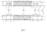
- Figure 3shows the sensor seen from above and from the side.
- Figure 4shows the temperature differences created by a full scale gas flow along the sensor.
- Figure 5shows the geometry of a sensitive resistive element of the sensor.
- FIG. 6shows the compared response times of a conventional sensor and of a sensor according to the invention.
- a flow meter 1is inserted on a gas circulation line, and has a gas inlet 2 and an outlet gas 3 (the direction of gas flow is symbolized by arrows).
- the gas circuitpresents in the flowmeter a laminar restriction 4 of the section of the tube, with in parallel a bypass passage 5 which circulates part of the gas flow in a capillary tube 6 in the sensor 7.
- the flow meter 1also includes a valve 8 for controlling the gas flow 2 which regulates the flow rate and an electronic circuit 9 which is comparator type (P.T.D. i.e. Proportional Integrator Diverter) between a setpoint transmitted from outside and the measurement made by the sensor.
- a loop of control 10of a type known to a person skilled in the art performs the servo control of the flow meter 1.
- the senor 7receives and heats a small part of the laminar flow (at full scale 10 cm 3 / min), which is proportional to the total flow.
- the mass flowis estimated from the heat transfer it generates: the temperature profile without gas circulation 11 along the tube 6 of the sensor 7 heated over part of its length is modified into an asymmetrical profile 12 when gas circulates in the tube 6, and this temperature difference ⁇ T between the upstream 13 and the downstream 14 of the tube is a measure of the mass flow.
- the flow sensorin the conventional device not in accordance with the invention, comprises, as can be seen in FIG. 2, two coils 15, 16 of resistive wire, which perform two functions simultaneously: heating and measuring the temperature.
- This temperature measurementis obtained by measuring the variation of the two resistors, conventionally mounted in a Wheatstone bridge.
- the application of a constant current between the terminals of the resistors which are chosen of equivalent value R (at the same temperature)causes the heating of the sensor tube in two close places.
- the temperature distributionis represented by curve 11 in FIG. 2 (the curve presents the value of the temperature on the ordinate, and the distance along the tube on the abscissa) and is naturally symmetrical with respect to the center 17 of the two resistances.
- the structure of the sensor according to the inventionis a sensor of the so-called "6-wire" type, of which the heating and measurement functions are separated, as seen in figure 3.
- the heatingis provided by a resistive wire 20 made of Nickel Chrome alloy, wound around the tube 6.
- the tube 6has an insulating layer 21 and two measuring means 22, 23 of temperature, which are variable resistances with temperature, obtained by the thin film technology.
- the coiled heating wire 20must have a resistance slightly variable with temperature, unlike measurement resistors 22, 23.
- the calculation of the position of the measurement resistors 22, 23 relative to the position resistive wire 20requires a presentation of the analytical calculation model used here, which distinguishes the temperature of the gas flowing in the tube 6 from the temperature of the tube 6 itself.
- This modeldistinguishes the different thermal flows, by tube length, coming into play in the sensor: the axial flow of thermal conduction in the tube 6, the radial flow exchanged enter the gas and the tube, the radial flow exchanged between the environment of the tube and the tube, the power injected per unit of length P (in W / m). In the calculations, it is considered that this power is injected into the thickness of the tube.
- the environment of the tubehas a thermal resistance denoted R T per unit of length (Km W -1 ).
- the tubehas a section S (m 2 ), and a thermal conductivity k (W m -1 K -1 ).
- the gas temperature, ⁇ g (K), and the tube temperature ⁇ p (K)are both the temperature rises from ambient temperature.
- F mis the mass flow of gas (kg s -1 ) in the sensor.
- the second equationallows us to replace in the first the temperature of the gas by the temperature of the tube.
- Equation 2gives the temperature of the tube
- the constants A, B, Care different and determined by the boundary conditions.
- the temperature of the gasis room temperature. This hypothesis leads to the elimination of one or two exponentials in equation 4.
- the gas temperature. its first and second derivativesare continuous at x - x r and x - -x r (see equation 2).
- FIG. 4shows the temperature differences created by a full-scale gas flow along the sensor 7. There is good agreement between the values measured with a thermocouple (curve 24) and the calculated values (curve 25).
- Figure 5shows this temperature difference due to a full scale nitrogen flow, calculated and measured with a thermocouple. The difference between the temperatures, symmetrically between the upstream and downstream of the heating coil, whether calculated or measured, is linear with respect to the gas flow rate. All these results show the reliability of the model and make it possible to extend it to the sensor tube 6 with its insulating layer 21, on which temperature measurements are difficult to perform.
- the capillary tube 6has an outside diameter of 0.9 mm for about 60 mm in length, it is made of stainless steel type 316L or equivalent.
- the resistive heating wire 20 usedis composed of a nickel alloy (75%) and Chrome (20%) which has the distinction of having a high resistivity (1.33 Ohm.mm2.m-1) and a low coefficient of variation of resistance as a function of temperature (10 ppm / ° C). It is therefore quite suitable for ensuring the heating function. Its diameter is 28 microns and it is powered by a current of 12.5 mA.
- the insulating layer 20is zirconia (ZrO2 chosen for its good stability and its good dielectric characteristics, deposited by electron gun on the tube capillary 21 of the sensor, over a thickness of 2.5 microns. It covers 20 mm out of the 60 mm tube length 6.
- two platinum resistors 22, 23are deposited (by depositing platinum through Nickel masks) which constitute the measurement resistances of tube temperature. Platinum, a stable, stainless material, obtained with very high purity, has a high temperature coefficient (CTR: 3.9 10-3 ° C-1). That's why it is often used for the realization of standard resistances.
- These two resistors 22, 23, placed symmetrically with respect to the center 17 of the coil of resistive wire 20,are mounted in a Wheatstone bridge.
- the length of the coil of resistive heating wireis approximately 6 mm. and the distance between the two measurement resistors 22, 23 is then 7 mm approximately. They are arranged symmetrically around the center 17 of the reel of resistive wire 20.
- the difference between the temperatures, i.e. between the two resistances of measurement 22, 23,is then proportional to the flow rate and its measurement therefore corresponds to a measurement of the flow circulating in the capillary 6.
- each measuring resistor 22, 23 in platinumis detailed on the Figure 5.
- the length 26 of the sensitive element 27 of each measurement resistanceis approximately 4.5 mm, and the width 28 is 100 microns.
- the contacts 31, 32are of greater thickness than the sensitive elements 27, to that their resistance can be considered negligible during the measurement.
- the insulating layer (ZrO2) 21, the sensitive elements 27 of the resistors 22, 23 in platinum, the contacts 31, 32 in platinumare produced in this order by deposition of thin layers with the electron gun .
- the substrate, the sensor tube 6 made of 316L stainless steel,is held on a heating support. In order to obtain two substantially equal resistances, it is preferable that the substrate holder is rotated during deposition.
- the sensitive platinum elementsare deposited, also with the electron gun, on capillaries 6 isolated by the zirconia layer 21, through nickel masks. Of them deposits and two gaps are necessary, due to the geometry desired for the measurement resistors 22, 23, one for the sensitive elements 27 in platinum, and the other for contacts 31, 32. They are obtained from the same platinum target. These two deposits are made under a residual pressure of less than 10-6 Torr.
- the thickness of the 22. 22 measurement resistorscan vary according to the needs from 2000 to 7000 Angstroms. She is to be determined according to the desired resistance value R.
- the capillaries 6are annealed for one hour at 300 ° C. to set the coefficient of variation of the resistors 22, 23 with the temperature (according to an effect conventionally used), the layer then reforming stably. This therefore makes it possible to obtain a sensor 7 capable of operating at high temperature.
- a resistanceis thus produced which is more reliable than a wound resistance, the coefficient varies over time during the aging of the protective varnish and the wire.
- the operating mode of the deviceis identical to the operation classical, with a Wheatstone bridge measurement of the difference between the resistances upstream 22 and downstream 23 in the direction of circulation of the fluid.
- the coil of resistive wire heating 20is supplied separately, in a controlled manner by the electronic card 9.
- sputteringis used and also provides easily reproducible results.
- yttria zirconiacan be used to replace pure zirconia. It is also clear that if the embodiment shows capillary tubes of 0.9 mm outside diameter (0.7 mm inside), other diameters are possible depending on the flow range envisaged for the flow meter, with the same principle treatment.
- the production methodas explained, can be used to manufacture mass flow meter sensors in which the heating and measurement functions are combined. It is then necessary to plan to carry out a deposition all around the tube, so as to obtain a uniform heating function of the tube.
- the deposit for measurement resistorsonly has so far been mentioned. It is obviously possible to replace the heating resistor 20, produced by winding in the embodiment described by way of example, by a deposited heating resistor.
Landscapes
- Physics & Mathematics (AREA)
- Fluid Mechanics (AREA)
- General Physics & Mathematics (AREA)
- Measuring Volume Flow (AREA)
Abstract
Description
Translated fromFrenchLa présente invention est du domaine des dispositifs de mesure de débit de fluidesdans une canalisation.
Le capteur de débit massique est destiné à être incorporé dans un débitmètremassique placé dans une chaíne de gestion et de contrôle de circulation de gaz de hautepureté par exemple.
Ces débitmètres massiques, comportent usuellement un tube capillaire decirculation du fluide, sur lequel les mesures représentatives du débit sont effectuées,disposé en parallèle avec le circuit principal de circulation du fluide.The present invention is in the field of devices for measuring the flow rate of fluids in a pipeline.
The mass flow sensor is intended to be incorporated into a mass flow meter placed in a chain for managing and controlling the circulation of high purity gas for example.
These mass flowmeters usually comprise a capillary tube for circulation of the fluid, on which the measurements representative of the flow are carried out, arranged in parallel with the main circuit for circulation of the fluid.
De nombreux types de débitmètres massiques sont déjà connus de l'homme del'art. Le principe des capteurs de débit à pont de Wheatstone et mesure de différence detempérature est connu depuis 1947 (brevet US Kronberger and Brown). Ils sont le plussouvent basés sur un chauffage local du fluide passant dans le tube capillaire, et unemesure de variation de résistance d'éléments résistifs en fonction de la température, laditemesure étant représentative du flux de gaz dans le tube, et donc du débit. Les deuxrésistances de mesure, de valeur égale, possédant une grande résistivité et un grandcoefficient de variation avec la température, sont le plus souvent simplement bobinéesautour du tube capillaire isolé (US Patent 3 938 384). Ces résistances, alimentées par uncourant constant, chauffent le tube mais servent donc également de moyens de mesure detempérature. Un des inconvénients de ce type de capteur est l'importante masse thermiquede ces résistances bobinées, ce qui engendre un temps de réponse assez long.Many types of mass flow meters are already known to the person ofart. The principle of Wheatstone bridge flow sensors and difference measurementtemperature has been known since 1947 (US patent Kronberger and Brown). They are the mostoften based on local heating of the fluid passing through the capillary tube, and ameasurement of resistance variation of resistive elements as a function of temperature, saidmeasurement being representative of the gas flow in the tube, and therefore of the flow rate. Bothmeasuring resistors, of equal value, with high resistivity and highcoefficient of variation with temperature, are most often simply woundaround the insulated capillary tube (US Patent 3,938,384). These resistors, powered by aconstant current, heat the tube but therefore also serve as means of measuringtemperature. One of the disadvantages of this type of sensor is the large thermal massof these wirewound resistors, which generates a fairly long response time.
Parmi les autres dispositifs connus, on peut citer la demande de brevet européen 0131 318 131 (Brookhorst 1984), qui pose le problème de la dérive du point zéro de mesurelorsque le fluide lui-même est de température variable, et suggère un principe de montagede capteur de débit à base de quatre résistances sensibles à la température déposées defaçon non détaillée sur une couche de nature non précisée. Les résistances sont montéesen pont de Wheatstone de façon classique.Among the other known devices, mention may be made of European patent application 0131 318 131 (Brookhorst 1984), which poses the problem of measurement zero point driftwhen the fluid itself is of variable temperature, and suggests an assembly principleflow sensor based on four temperature sensitive resistors removed fromnot detailed on a layer of unspecified nature. The resistors are mountedin Wheatstone bridge in a classic way.
Dans une autre demande (EP 0 395 126 B1), Bronkhorst propose une géométrie detube en U très allongé, et doté de séries de thermocouples placés symétriquement et d'unerésistance chauffante centrale en deux parties, ainsi éventuellement que d'éléments derefroidissement Peltier, pour palier les problèmes d'erreur de mesure liée à une circulationd'air à l'extérieur du capteur ou de convection interne au tube capillaire.In another application (EP 0 395 126 B1), Bronkhorst proposes a geometry ofvery elongated U-tube, with series of symmetrically placed thermocouples and acentral heating resistor in two parts, as well as elements ofPeltier cooling, to overcome the problems of measurement error linked to a circulationair outside the sensor or internal convection to the capillary tube.
Le brevet US 5 373 737 (Goldstar 1993) présente un capteur de débitmètremassique insensible aux variations de température extérieure, utilisant deux résistancesbobinées à l'extérieur du tube de circulation de fluide, montées en pont de Wheatstone etun élément de refroidissement placées dans une enceinte thermiquement isolée.US Patent 5,373,737 (Goldstar 1993) presents a flowmeter sensormass insensitive to outside temperature variations, using two resistorswound on the outside of the fluid circulation tube, mounted in a Wheatstone bridge anda cooling element placed in a thermally insulated enclosure.
De même, le brevet US 5 410 912 (MKS 1994) dévoile un capteur de débitmètremassique, dans lequel deux résistances sont utilisées avec un montage en pont, leditcapteur étant indépendant des variations de température ambiante par l'intermédiaire d'uneenceinte spécifique du tube au point de mesure. L'une des résistance sert au chauffage etl'autre à la mesure de résistance fonction de la température atteinte.
De nombreux autres documents brevets concernent des capteurs de débitmassique. L'article "A calibration system for calorimetric mass flow devices" (Widmer,Felhmann, Rehwald, J. Phys, E: Sci. Instr Vol 15 1982 pp 213) présente de façon globaleles diverses technologies existantes pour les débitmètres depuis 1900 et les évolutions. Unarticle de présentation de fond sur l'évolution technique récente des débitmètres massiquesest fourni par "Récent Advances in Mass Flow Controls", pp 86, Solid State Technology,9/94.Likewise, US Patent 5,410,912 (MKS 1994) discloses a mass flowmeter sensor, in which two resistors are used with a bridge mounting, said sensor being independent of variations in ambient temperature by means of a specific enclosure. from the tube to the measuring point. One of the resistors is used for heating and the other for resistance measurement depending on the temperature reached.
Many other patent documents relate to mass flow sensors. The article "A calibration system for calorimetric mass flow devices" (Widmer, Felhmann, Rehwald, J. Phys, E: Sci. Instr Vol 15 1982 pp 213) presents in a general way the various existing technologies for flowmeters since 1900 and the developments. A background article on recent technical developments in mass flow meters is provided by "Recent Advances in Mass Flow Controls", pp 86, Solid State Technology, 9/94.
Le capteur selon le brevet DE 43 35 332 comprend un tube de mesure 12 doté d'unélément chauffant 18 médian de part et d'autre duquel sont disposés des capteurs detempérature 20, 22, 24, 26, 28 (d'un côté) et 30, 32, 34, 36, 38 de l'autre côté, soit 5 dechaque côté.
Comme mentionné en colonne 4, lignes 22 à 44, le but de ce montage est d'obtenirune pluralité de données à partir de la mesure d'un profil de température, cette mesures'effectuant en plusieurs points amont et aval par rapport à l'élément chauffant.The sensor according to patent DE 43 35 332 comprises a measurement tube 12 provided with a central heating element 18 on either side of which are arranged temperature sensors 20, 22, 24, 26, 28 (on one side ) and 30, 32, 34, 36, 38 on the other side, i.e. 5 on each side.
As mentioned in column 4, lines 22 to 44, the purpose of this arrangement is to obtain a plurality of data from the measurement of a temperature profile, this measurement being carried out at several points upstream and downstream relative to the heating element.
Le brevet européen 0 809 090 décrit dans son résumé un débitmètremassique comportant un tube de circulation composite comprenant quatre segmentstubulaires à haute conductivité thermique réalisés dans la longueur d'un tube ayant lui-mêmeune relativement basse conductivité thermique, un film étant formé à la surface ettout autour de chacun des quatre segments tubulaires.European patent 0 809 090 describes in its summary a flowmetermass comprising a composite circulation tube comprising four segmentstubulars with high thermal conductivity made in the length of a tube having itselfrelatively low thermal conductivity, a film being formed on the surface andall around each of the four tubular segments.
Le brevet DE 43 35 332, colonne 3. lignes 8 à 62 ne semble pas suggérer lapossibilité de calculer la position des résistances sur le tube.DE 43 35 332, column 3. lines 8 to 62 does not seem to suggest thepossibility of calculating the position of the resistors on the tube.
Le brevet DE 43 35 332 se base sur une multitude de points de mesure en amontet en aval pour déterminer le débit massique alors que l'invention de la SociétéQUALIFLOW se base sur le calcul de la position précise de la résistance (pont de mesure)amont et de la résistance aval pour établir le débit massique.Patent DE 43 35 332 is based on a multitude of upstream measurement pointsand downstream to determine the mass flow while the invention of the CompanyQUALIFLOW is based on the calculation of the precise position of the resistance (measuring bridge)upstream and downstream resistance to establish the mass flow.
Comme on le voit, de nombreuses conceptions de capteurs thermiques de débit defluide ont été proposées par les différents constructeurs, pour tenter de palier lesproblèmes de précision de mesure si le capteur est à l'extérieur du tube capillaire, decorrosion si le capteur est placé à l'intérieur du tube, de dérive du point de référence enfonction de la température intrinsèque du fluide, de phénomène parasite de transfert dechaleur à l'intérieur ou à l'extérieur du tube, d'imprécision de fabrication ou de nonreproductibilité de la fabrication.
Les capteurs de faible débit (10 à 20 ce/minute) présentent plusieurs défautsprincipaux : temps de réponse, gamme de mesure peu étendue, précision (Drexel :"Digital mass flow controllers come of age", Solid State Technology 11/96).
Le temps de reponse des dispositifs existants est de l'ordre de la dizaine desecondes au niveau du capteur (mesuré en temps de convergence des oscillations à 67%de leur valeur d'équilibre), ce temps étant amélioré (réduit d'un facteur trois typiquement)par l'utilisation de carte électronique à PID (Proportionnel Intégrateur Dérivateur) quianticipe les oscillations de mesure du capteur et prédit la valeur de convergence. Une cartedigitale donnant les valeurs précises des paramètres de modélisation des oscillations ducapteur permet encore d'améliorer ce temps, de façon artificielle.
Le problème du temps de réponse du capteur lui-même, qui est présent pour tousles capteurs de débit massique, est particulièrement sensible pour les débitmètre à faibledébit, de l'ordre de 10 à 50 ce/minute, pour lesquels le temps de convergence du capteurpeut atteindre plusieurs minutes. Ces capteurs sont alors très difficiles à étalonnerprécisément (voir "Flow Measurement and Control in Vacuum Systems forMicroelectronics Processing", Sullivan, Jacobs, Solid State Technology, Oct 86). Leproblème du temps de réponse, considéré comme un point critique, a été abordé enparticulier dans la demande de brevet FR 2 530 014, avec une solution constituée d'unedisposition particulière de trois enroulements bobinés autour du tube bout à bout, avec unenroulement amont de chauffage, un enroulement intermédiaire de mesure et de chauffage supplémentaire, et un enroulement aval de refroidissement entre les températures crééespar les deux premiers enroulements.
Il est a noter que dans d'autres systèmes, on fait varier le courant de façon àmaintenir la température toujours constante, et on en déduit alors le débit Il s'agit alorsd'un problème de pilotage et donc de carte électronique plus complexe (voir EP 0 522 496A1. Nippondenso, 1992).As can be seen, many designs of thermal fluid flow sensors have been proposed by the various manufacturers, in an attempt to alleviate the problems of measurement accuracy if the sensor is outside the capillary tube, of corrosion if the sensor is placed inside the tube, drift from the reference point as a function of the intrinsic temperature of the fluid, parasitic phenomenon of heat transfer inside or outside the tube, imprecision of manufacturing or non-reproducibility of manufacturing.
Low flow sensors (10 to 20 cc / minute) have several main faults: response time, limited measurement range, precision (Drexel: "Digital mass flow controllers come of age", Solid State Technology 11/96).
The response time of existing devices is around ten seconds at the sensor (measured in time of convergence of the oscillations at 67% of their equilibrium value), this time being improved (reduced by a factor typically three) by the use of a PID (Proportional Integrator Diverter) electronic card which anticipates the sensor measurement oscillations and predicts the convergence value. A digital map giving the precise values of the parameters for modeling the oscillations of the sensor makes it possible to improve this time, artificially.
The problem of the response time of the sensor itself, which is present for all mass flow sensors, is particularly sensitive for flow meters with low flow rates, of the order of 10 to 50 cc / minute, for which the time of sensor convergence can reach several minutes. These sensors are therefore very difficult to calibrate precisely (see "Flow Measurement and Control in Vacuum Systems for Microelectronics Processing", Sullivan, Jacobs, Solid State Technology, Oct 86). The problem of response time, considered to be a critical point, was tackled in particular in patent application FR 2 530 014, with a solution consisting of a particular arrangement of three windings wound around the tube end to end, with a upstream heating winding, an intermediate measurement and additional heating winding, and a downstream cooling winding between the temperatures created by the first two windings.
It should be noted that in other systems, the current is varied so as to keep the temperature always constant, and the flow is then deduced therefrom. It is then a problem of control and therefore of a more complex electronic card. (see EP 0 522 496 A1. Nippondenso, 1992).
La présente invention propose un procédé de réalisation d'un capteur pour débitmètre massique permetune fabrication de capteurs de caractéristiques connues précisément, reproductibles etstables dans le temps.The present invention provides a method for producing a sensor for mass flow meter allowsmanufacture of sensors with precisely known characteristics, reproducible andstable over time.
Selon des dispositions particulières, le procédé deréalisation d'un capteur pour débitmère massique comportant un tube capillaire de circulation du fluide en parallèleavec le circuit principal de circulation du fluide et destiné à être incorporé dans un circuitde circulation de fluides gazeux, constitué de moyens de chauffage du tube capillaire et demoyens de mesure de température en amont et en aval de ce moyen de chauffage distinctsdudit moyen de chauffage, les moyens de mesure de température prennent la forme dedeux résistances réalisées par dépôt de façon externe sur le tube capteur, l'une en amontdu moyen de chauffage, l'autre en aval de ce moyen, une couche isolante étantpréalablement déposée sur le tube, se caractérise en ce que la position relative desrésistances est déterminée par un modèle de calcul analytique qui distingue les différentsflux thermiques, par longueur de tube, entrant en jeu dans le capteur ; le flux axial deconduction thermique dans le tube, le flux radial échangé entre l'environnement du tube etla puissance injectée par unité de longueur.According to specific provisions, the process ofproduction of a mass flow sensor comprising a capillary tube for circulation of the fluid in parallelwith the main fluid circulation circuit and intended to be incorporated in a circuitcirculation of gaseous fluids, consisting of means for heating the capillary tube andtemperature measurement means upstream and downstream of this separate heating meansof said heating means, the temperature measuring means take the form oftwo resistors produced by depositing externally on the sensor tube, one upstreamheating means, the other downstream of this means, an insulating layer beingpreviously deposited on the tube, is characterized in that the relative position of theresistances is determined by an analytical calculation model which distinguishes the differentheat fluxes, by length of tube, coming into play in the sensor; the axial flow ofthermal conduction in the tube, the radial flow exchanged between the environment of the tube andthe power injected per unit of length.
L'invention vise également le procédé de réalisation de tube capteur destiné à êtreincorporé dans un débitmètre massique, comportant les étapes suivantes :
- calcul de la distance de positionnement des résistances en fonction des équationscaractérisant les températures du tube et de l'écoulement gazeux,
- dépôt de la couche isolante au canon à électrons, par ajout d'oxygène dansl'enceinte.
- puis dépôt des résistances en platine, au canon à électrons, sur des capillairesisolés par la couche de zircone, à travers des masques de Nickel, à une pression résiduelleinférieure à 10-6 Torr, sur une épaisseur de quelques milliers d'Angströms.
- puis dépôt des contacts en platine, au canon à électrons, sur des capillaires isoléspar la couche de zircone, à travers des masques de Nickel, à une pression résiduelleinférieure à 10-6 Torr, sur une épaisseur de quelques microns.
- calculation of the positioning distance of the resistors according to the equations characterizing the temperatures of the tube and the gas flow,
- deposition of the insulating layer with the electron gun, by adding oxygen to the enclosure.
- then depositing platinum resistances, with an electron gun, on capillaries isolated by the zirconia layer, through nickel masks, at a residual pressure less than 10-6 Torr, over a thickness of a few thousand Angstroms.
- then depositing the platinum contacts, using an electron gun, on capillaries isolated by the zirconia layer, through nickel masks, at a residual pressure less than 10-6 Torr, over a thickness of a few microns.
Le procédé de réalisation de capteur selon l'invention se caractérise en ce que lalongueur de la bobine de fil résistif constituant l'élément chauffant, l'emplacement et lalongueur des résistances de température sont déterminés par le modèle de calcul.The method of producing a sensor according to the invention is characterized in that thelength of the coil of resistive wire constituting the heating element, the location and thelength of the temperature resistors are determined by the calculation model.
Suivant une autre disposition, le procédé se caractérise en ce que le calcul de ladistance de positionnement des résistances de mesure par rapport au moyen de chauffageest fait en fonction des équations caractérisant les températures du tube et de l'écoulementgazeux.
Le procédé se caractérise également en ce que le dépôt de la couche isolante estréalisé au canon à électrons, par ajout d'oxygène dans l'enceinte.
Le procédé se caractérise également en ce que le dépôt des résistances de mesureest réalisé au moyen d'un canon à électrons, sur des capillaires isolés par une couche dezircone à travers des masques de Nickel.
Le procédé se caractérise également en ce que le dépôt des contacts en platine estréalisé au moyen d'un canon à électrons, sur des capillaires (6) isolés par la couche dezircone à travers des masques de Nickel.
Le procédé se caractérise encore en ce que le dépôt des contacts ou élémentssensibles en platine est réalisé à une pression résiduelle inférieure à 10-6 Torr.
Le procédé se caractérise encore en ce qu'il compoxte en outre en fin de traitementune étape de recuit des capteurs de une heure à 300°C.According to another arrangement, the method is characterized in that the calculation of the positioning distance of the measurement resistors relative to the heating means is made according to the equations characterizing the temperatures of the tube and of the gas flow.
The method is also characterized in that the deposition of the insulating layer is carried out with an electron gun, by adding oxygen to the enclosure.
The method is also characterized in that the deposition of the measurement resistors is carried out by means of an electron gun, on capillaries insulated by a layer of zirconia through nickel masks.
The method is also characterized in that the deposition of the platinum contacts is carried out by means of an electron gun, on capillaries (6) isolated by the zirconia layer through masks of Nickel.
The method is further characterized in that the deposition of the contacts or sensitive elements in platinum is carried out at a residual pressure of less than 10-6 Torr.
The method is further characterized in that it additionally comprises at the end of the treatment a step of annealing the sensors for one hour at 300 ° C.
La détermination de la position des points correspondant à une différencemaximale de température entre les résistances de mesure est réalisée par utilisation deséquations caractérisant les températures du tube d'une part et de l'écoulement d'autre part,ce que ne permettent pas avec précision les modèles théoriques traditionnels à une seule équation. Ces calculs ont été confirmés par des calculs numériques réalisés avec unlogiciel de simulation.
Le choix de dépôt de l'isolant et des éléments de mesure au canon à électronspermet d'obtenir un contact extrêmement intime des résistances avec le tube isolé, doncun temps de réponse très court du capteur.
Les capteurs précédemment connus, au contraire, utilisent un dépôt épais collé etnon déposé, avec des questions de fiabilité du contact et donc de reproductibilité de lamesure réalisée par ces capteurs. Il est également possible ici de réaliser une couche dedépôt d'épaisseur réduite à 2,5 microns au lieu des dizaines de microns courammentconnus.
Enfin, une procédure reproductible est réalisée, avec donc la capacité à produire engrande série des capteurs de caractéristiques exactement identiques.
Le choix de cette technologie permet également de réaliser des résistances sur dessurface courbes de capteurs (tube cylindrique), ce que ne permettent pas correctement lestechnologies précédentes.The determination of the position of the points corresponding to a maximum temperature difference between the measurement resistors is carried out by using equations characterizing the temperatures of the tube on the one hand and of the flow on the other hand, which is not possible with precision traditional theoretical models with a single equation. These calculations were confirmed by numerical calculations carried out with simulation software.
The choice of deposition of the insulator and of the measurement elements with the electron gun makes it possible to obtain an extremely intimate contact of the resistances with the insulated tube, therefore a very short response time of the sensor.
The previously known sensors, on the contrary, use a thick bonded and not deposited deposit, with questions of reliability of the contact and therefore of reproducibility of the measurement carried out by these sensors. It is also possible here to produce a deposit layer with a thickness reduced to 2.5 microns instead of the tens of microns commonly known.
Finally, a reproducible procedure is carried out, with therefore the ability to mass produce sensors with exactly identical characteristics.
The choice of this technology also makes it possible to produce resistances on curved surfaces of sensors (cylindrical tube), which the previous technologies do not allow correctly.
Selon un mode de réalisation préféré, le procédé de réalisation de tube capteur secaractérise en ce qu'il comporte en outre, en fin de traitement, une étape de recuit destubes de une heure à 300°C.According to a preferred embodiment, the method for producing a sensor tube ischaracterized in that it further comprises, at the end of treatment, a step of annealing theone hour tubes at 300 ° C.
La description qui va suivre, faite en regard des dessins annexés dans un butexplicatif permet de mieux comprendre les avantages, buts etcaractéristiques de l'invention.
La figure 1 représente le schéma fonctionnel d'un débitmètre de technologieclassique.
La figure 2 montre le principe de fonctionnement classique d'un capteur de débitmassique.
La figure 3 représente le capteur vu de dessus et de côté.
La figure 4 montre les écarts de température créés par un débit de gaz à pleineéchelle le long du capteur.
La figure 5 montre la géométrie d'un élément résistif sensible du capteur.
La figure 6 montre les temps de réponse comparés d'un capteur classique et d'uncapteur selon l'invention.The description which follows, made with reference to the accompanying drawings for explanatory purposes makes it possible to better understand the advantages, aims and characteristics of the invention.
Figure 1 shows the block diagram of a flowmeter of conventional technology.
Figure 2 shows the classic operating principle of a mass flow sensor.
Figure 3 shows the sensor seen from above and from the side.
Figure 4 shows the temperature differences created by a full scale gas flow along the sensor.
Figure 5 shows the geometry of a sensitive resistive element of the sensor.
FIG. 6 shows the compared response times of a conventional sensor and of a sensor according to the invention.
Tel que schématisé selon une disposition classique sur la figure 1, un débitmètre 1est inséré sur une ligne de circulation de gaz, et comporte une entrée de gaz 2 et une sortiede gaz 3 (le sens de circulation du gaz est symbolisé par des flèches). Le circuit de gazprésente dans le débitmètre une restriction laminaire 4 de la section du tube, avec enparallèle un passage de dérivation (bypass) 5 qui fait circuler une partie du flux gazeuxdans un tube capillaire 6 dans le capteur 7. Le débitmètre 1 comporte également unevanne 8 de contrôle du flux gazeux 2 qui régule le débit et un circuit électronique 9 qui estde type comparateur (P.T.D. c'est à dire Proportionnel Intégrateur Dérivateur) entre uneconsigne transmise de l'extérieur et la mesure réalisée par le capteur. Une boucle decontrôle 10 de type connu de l'homme de l'art réalise l'asservissement de fonctionnementdu débitmètre 1.As shown schematically according to a conventional arrangement in Figure 1, a flow meter 1is inserted on a gas circulation line, and has a gas inlet 2 and an outletgas 3 (the direction of gas flow is symbolized by arrows). The gas circuitpresents in the flowmeter a laminar restriction 4 of the section of the tube, with inparallel a bypass passage 5 which circulates part of the gas flowin a capillary tube 6 in the sensor 7. The flow meter 1 also includes avalve 8 for controlling the gas flow 2 which regulates the flow rate and an electronic circuit 9 which iscomparator type (P.T.D. i.e. Proportional Integrator Diverter) between asetpoint transmitted from outside and the measurement made by the sensor. A loop ofcontrol 10 of a type known to a person skilled in the art performs the servo controlof the flow meter 1.
En ce qui concerne son principe, le capteur 7 reçoit et chauffe une petite partie dudébit laminaire (à pleine échelle 10 cm3/mn), qui est proportionnelle au débit total. Ledébit massique est estimé à partir du transfert thermique qu'il engendre : le profil detempérature sans circulation de gaz 11 le long du tube 6 du capteur 7 chauffé sur unepartie de sa longueur est modifié en un profil dissymétrique 12 lorsque du gaz circule dansle tube 6, et cette différence de température ΔT entre l'amont 13 et l'aval 14 du tube estune mesure du débit massique.With regard to its principle, the sensor 7 receives and heats a small part of the laminar flow (at full scale 10 cm3 / min), which is proportional to the total flow. The mass flow is estimated from the heat transfer it generates: the temperature profile without gas circulation 11 along the tube 6 of the sensor 7 heated over part of its length is modified into an asymmetrical profile 12 when gas circulates in the tube 6, and this temperature difference ΔT between the upstream 13 and the downstream 14 of the tube is a measure of the mass flow.
Le capteur de débit, dans le dispositif classique non conforme à l'invention,comporte comme on le voit sur la figure 2 deux bobines 15, 16 de fil résistif, qui assurentdeux fonctions simultanément : le chauffage et la mesure de la température.
Cette mesure de température est obtenue en mesurant la variation des deuxrésistances, montées de façon classique dans un pont de Wheatstone. L'application d'uncourant constant entre les bornes des résistances qui sont choisies de valeur équivalente R(à même température) provoque le chauffage du tube capteur en deux endroits proches.
En l'absence de circulation de gaz dans le capillaire, la répartition de températureest représentée par la courbe 11 sur la figure 2 (la courbe présente la valeur de latempérature en ordonnée, et la distance le long du tube en abscisse) et est naturellementsymétrique par rapport au centre 17 des deux résistances. Au contraire, dans le cas decirculation de gaz dans le tube (courbe 12), la répartition de température est asymétrique,et on observe entre deux points équidistants 18, 19 du centre 17 des résistances unedifférence de température ΔT, qui se traduit par des mesures de résistance différentes pourles deux éléments résistifs, R-δR et R+δR.The flow sensor, in the conventional device not in accordance with the invention, comprises, as can be seen in FIG. 2, two coils 15, 16 of resistive wire, which perform two functions simultaneously: heating and measuring the temperature.
This temperature measurement is obtained by measuring the variation of the two resistors, conventionally mounted in a Wheatstone bridge. The application of a constant current between the terminals of the resistors which are chosen of equivalent value R (at the same temperature) causes the heating of the sensor tube in two close places.
In the absence of gas circulation in the capillary, the temperature distribution is represented by curve 11 in FIG. 2 (the curve presents the value of the temperature on the ordinate, and the distance along the tube on the abscissa) and is naturally symmetrical with respect to the center 17 of the two resistances. On the contrary, in the case of gas circulation in the tube (curve 12), the temperature distribution is asymmetrical, and a difference in temperature ΔT is observed between two equidistant points 18, 19 from the center 17 of the resistances, which results in different resistance measurements for the two resistive elements, R-δR and R + δR.
La structure du capteur selon l'invention est un capteur du type dit "à 6 fils", dontles fonctions chauffage et mesure sont séparées, comme on le voit sur la figure 3. Lechauffage est assuré par un fil résistif 20 en alliage Nickel Chrome, bobiné autour du tube6. Le tube 6 présente une couche isolante 21 et deux moyens de mesure 22, 23 detempérature, qui sont des résistances variables avec la température, obtenus par latechnologie des couches minces. Le fil bobiné 20 de chauffage doit avoir une résistancefaiblement variable avec la température, au contraire des résistances de mesure 22, 23. Ona au total 6 fils de connexion du capteur (2 par résistance de mesure et 2 pour le filrésistif), d'où son nom.The structure of the sensor according to the invention is a sensor of the so-called "6-wire" type, of whichthe heating and measurement functions are separated, as seen in figure 3. Theheating is provided by a resistive wire 20 made of Nickel Chrome alloy, wound around the tube6. The tube 6 has an insulating layer 21 and two measuring means 22, 23 oftemperature, which are variable resistances with temperature, obtained by thethin film technology. The coiled heating wire 20 must have a resistanceslightly variable with temperature, unlike measurement resistors 22, 23. Wehas a total of 6 sensor connection wires (2 per measurement resistor and 2 for the wireresistive), hence its name.
Le calcul de la position des résistances de mesure 22, 23 par rapport à la positiondu fil résistif 20 nécessite une présentation du modèle de calcul analytique utilisé ici, quidistingue la température du gaz circulant dans le tube 6 de la température du tube 6 elle-même.The calculation of the position of the measurement resistors 22, 23 relative to the positionresistive wire 20 requires a presentation of the analytical calculation model used here, whichdistinguishes the temperature of the gas flowing in the tube 6 from the temperature of the tube 6 itself.
Ce modèle distingue les différents flux thermiques, par longueur de tube, entranten jeu dans le capteur : le flux axial de conduction thermique dans le tube 6, le flux radialéchangé entrez le gaz et le tube, le flux radial échangé entre l'environnement du tube et letube, la puissance injectée par unité de longueur P (en W/m).
Dans les calculs, il est considéré que cette puissance est injectée dans l'épaisseurdu tube. L'environnement du tube a une résistance thermique notée RT par unité delongueur (Km W-1). Le tube a une section S (m2), et une conductivité thermique k (W m-1K-1).
La température du gaz, g (K), et la température du tube p (K), sont toutes lesdeux les élévations de température par rapport à la température ambiante. Elles nedépendent que de leur position x le long du tube 6, dont l'origine est le centre 17 de labobine de chauffage.
Pour un petit élément du tube, la somme de ces différents flux thermiques doit êtrenulle en régime permanent. Ceci amène à l'équation suivante:
D'autre part, la somme du. flux transporté par le gaz et du flux échangé entre le gazet le tube doit être nulle également :
In the calculations, it is considered that this power is injected into the thickness of the tube. The environment of the tube has a thermal resistance denoted RT per unit of length (Km W-1 ). The tube has a section S (m2 ), and a thermal conductivity k (W m-1 K-1 ).
The gas temperature, g (K), and the tube temperature p (K), are both the temperature rises from ambient temperature. They only depend on their position x along the tube 6, the origin of which is the center 17 of the heating coil.
For a small element of the tube, the sum of these different heat fluxes must be zero in steady state. This leads to the following equation:
On the other hand, the sum of. flow transported by the gas and the flow exchanged between the gas and the tube must also be zero:
Le tube est divisé en trois zones. Pour un tube d'une longueur 2×L, chauffé parune bobine d'une longueur 2×xr ces trois zones sont : -L< x < xr, la zone amont (P=0), -xr< x < xr la zone de chauffage (P est égale à l'effet Joule par unité de longueur et detemps), xr < x < L la zone aval (P=0). La deuxième équation nous permet de remplacerdans la première la température du gaz par la température du tube.
On obtient une équation différentielle du troisième degré pour la température dugaz:
We obtain a third degree differential equation for the gas temperature:
On peut noter ω1, ω2 et ω3 les trois racines de l'équation caractéristique de latempérature du gaz. La solution générale de l'équation (3) s'écrit :
L'équation 2 donne la température du tube où α = Nu πλ / Cp
A l'infini, très loin de la résistance chauffante, la température du gaz est latempérature ambiante, Cette hypothèse conduit à éliminer une ou deux exponentiellesdans l'équation 4.We can note ω1, ω2 and ω3 the three roots of the equation characteristic of the gas temperature. The general solution of equation (3) is written:
Equation 2 gives the temperature of the tube where α = Nu πλ / Cp
At infinity, very far from the heating resistance, the temperature of the gas is room temperature. This hypothesis leads to the elimination of one or two exponentials in equation 4.
La température du gaz. ses première et deuxième dérivées sont continues à x- xr etx- -xr (voir equation 2).The gas temperature. its first and second derivatives are continuous at x- xr and x- -xr (see equation 2).
La figure 4 montre les écarts de température créés par un débit de gaz à pleineéchelle le long du capteur 7. On constate un bon accord entre les valeurs mesurées authermocouple (courbe 24) et le valeurs calculées (courbe 25). La figure 5 présente cetécart de température dû à un débit d'azote à pleine échelle, calculé et mesuré authermocouple. La différence entre les températures, symétriquement entre l'amont etl'aval de la bobine chauffante, qu'elles soient calculées ou mesurées, est linéaire parrapport au débit de gaz.
Tous ces résultats montrent la fiabilité du modèle et permettent de l'étendre autube capteur 6 avec sa couche isolante 21, sur lequel des mesures de température sontdifficiles à effectuer.FIG. 4 shows the temperature differences created by a full-scale gas flow along the sensor 7. There is good agreement between the values measured with a thermocouple (curve 24) and the calculated values (curve 25). Figure 5 shows this temperature difference due to a full scale nitrogen flow, calculated and measured with a thermocouple. The difference between the temperatures, symmetrically between the upstream and downstream of the heating coil, whether calculated or measured, is linear with respect to the gas flow rate.
All these results show the reliability of the model and make it possible to extend it to the sensor tube 6 with its insulating layer 21, on which temperature measurements are difficult to perform.
Les différents modèles thermiques analytiques classiques du capteur considèrentque la température du gaz est égale à la température du tube.
- En fait, la température du gaz peut être très différente de la température dutube si le gaz a une faible diffusivité thermique, comme l'azote par exemple.Cette diffusivité thermique, noté a = λ /pCp apparaít dans la deuxième équation :
Considérer les propriétés du gaz constantes le long du tube et les choisir à unetempérature moyenne ne doit pas engendrer d'erreur significative. En effet, la capacitécalorifique de la plupart des gaz ne dépend pas de la température.
La variation de la densité des gaz en fonction de la température a cependant uneinfluence si le capteur est parallèle à la force de gravité.The various conventional analytical thermal models of the sensor consider that the temperature of the gas is equal to the temperature of the tube.
- In fact, the temperature of the gas can be very different from the temperature of the tube if the gas has a low thermal diffusivity, like nitrogen for example. This thermal diffusivity, noted a = λ /p Cp appears in the second equation:
Considering the properties of the gas constant along the tube and choosing them at an average temperature should not cause significant error. Indeed, the heat capacity of most gases does not depend on the temperature.
The variation of the density of the gases as a function of the temperature however has an influence if the sensor is parallel to the force of gravity.
De ces calculs on déduit :
- la longueur de la bobine de fil résistif 20, pour avoir une bonnesensibilité,
- l'emplacement et la longueur des résistances de température 22, 23. Ilsdoivent être proche de la bobine 20, où la température du tube 6 est le plus modifiée par legaz.
- the length of the coil of resistive wire 20, to have good sensitivity,
- the location and the length of the temperature resistors 22, 23. They must be close to the coil 20, where the temperature of the tube 6 is most modified by the gas.
Une fois les dimensions déterminées conformément à ce qui vient d'être exposé, laréalisation du capteur 7 se fait de la façon suivante. Dans la mise en oeuvre présentée àtitre non limitatif (figure 3). le tube capillaire 6 a un diamètre extérieur de 0,9 mm pourenviron 60 mm de longueur, il est composé d'acier inoxydable de type 316L ouéquivalent. Le fil résistif 20 de chauffage utilisé est composé d'un alliage Nickel (75%) etChrome (20%) qui a la particularité d'avoir une résistivité élevée (1,33 Ohm.mm2.m-1) etun faible coefficient de variation de la résistance en fonction de la température (10ppm/°C). Il convient donc tout à fait pour assurer la fonction chauffage. Son diamètre estde 28 microns et il est alimenté par un courant de 12,5 mA.Once the dimensions have been determined in accordance with what has just been explained, therealization of the sensor 7 is done as follows. In the implementation presented tonon-limiting title (Figure 3). the capillary tube 6 has an outside diameter of 0.9 mm forabout 60 mm in length, it is made of stainless steel type 316L orequivalent. The resistive heating wire 20 used is composed of a nickel alloy (75%) andChrome (20%) which has the distinction of having a high resistivity (1.33 Ohm.mm2.m-1) anda low coefficient of variation of resistance as a function of temperature (10ppm / ° C). It is therefore quite suitable for ensuring the heating function. Its diameter is28 microns and it is powered by a current of 12.5 mA.
La couche isolante 20 est de la zircone (ZrO2 choisie pour sa bonne stabilité etses bonnes caractéristiques diélectriques, déposée par canon à électrons sur le tubecapillaire 21 du capteur, sur une épaisseur de 2,5 microns. Elle couvre 20 mm sur les 60mm de longueur du tube 6.The insulating layer 20 is zirconia (ZrO2 chosen for its good stability andits good dielectric characteristics, deposited by electron gun on the tubecapillary 21 of the sensor, over a thickness of 2.5 microns. It covers 20 mm out of the 60mm tube length 6.
Sur cette couche, on dépose deux résistances de platine 22, 23 (par dépôt deplatine à travers des masques de Nickel) qui constituent les résistances de mesure detempérature du tube. Le platine, matériau stable, inoxydable, obtenu avec une très grandepureté, a un fort coefficient de température (CTR : 3.9 10-3 °C-1). C'est pourquoi il estsouvent utilisé pour la réalisation de résistances étalons. Ces deux résistances 22, 23,placées symétriquement par rapport au centre 17 de la bobine de fil résistif 20, sontmontées dans un pont de Wheatstone. La longueur du bobinage en fil résistif de chauffageest d'environ 6 mm. et la distance entre les deux résistances de mesure 22, 23 est alors de7 mm environ. Elles sont disposées symétriquement autour du centre 17 de la bobine defil résistif 20.On this layer, two platinum resistors 22, 23 are deposited (by depositingplatinum through Nickel masks) which constitute the measurement resistances oftube temperature. Platinum, a stable, stainless material, obtained with very highpurity, has a high temperature coefficient (CTR: 3.9 10-3 ° C-1). That's why it isoften used for the realization of standard resistances. These two resistors 22, 23,placed symmetrically with respect to the center 17 of the coil of resistive wire 20, aremounted in a Wheatstone bridge. The length of the coil of resistive heating wireis approximately 6 mm. and the distance between the two measurement resistors 22, 23 is then7 mm approximately. They are arranged symmetrically around the center 17 of the reel ofresistive wire 20.
La différence entre les températures, c'est à dire entre les deux résistances demesure 22, 23, est alors proportionnelle au débit et sa mesure correspond donc à unemesure du débit circulant dans le capillaire 6.The difference between the temperatures, i.e. between the two resistances ofmeasurement 22, 23, is then proportional to the flow rate and its measurement therefore corresponds to ameasurement of the flow circulating in the capillary 6.
La géométrie de chaque résistance de mesure 22, 23 en platine est détaillée sur lafigure 5. Dans cette réalisation, la longueur 26 de l'élément sensible 27 de chaquerésistance de mesure est d'environ 4,5 mm, et la largeur 28 est de 100 microns. L'élémentsensible 27 a ses extrémités 29, 30 solidaires de deux contacts 31, 32 de connexion auxfils de mesure (non représentés), sous la forme de volumes de section rectangulaireégalement réalisés en platine, de 400 microns de large par 50 microns de long. Lescontacts 31, 32 sont d'une épaisseur plus importante que les éléments sensibles 27, pourque leur résistance puisse être considérée négligeable lors de la mesure.The geometry of each measuring resistor 22, 23 in platinum is detailed on theFigure 5. In this embodiment, the length 26 of the sensitive element 27 of eachmeasurement resistance is approximately 4.5 mm, and the width 28 is 100 microns. The elementsensitive 27 at its ends 29, 30 integral with two contacts 31, 32 for connection tomeasuring wires (not shown), in the form of volumes of rectangular sectionalso made of platinum, 400 microns wide by 50 microns long. Thecontacts 31, 32 are of greater thickness than the sensitive elements 27, tothat their resistance can be considered negligible during the measurement.
En ce qui concerne la fabrication proprement dite, la couche isolante (ZrO2) 21,les éléments sensibles 27 des résistances 22, 23 en platine, les contacts 31, 32 en platinesont réalisés dans cet ordre par dépôts de couches minces au canon à électrons.
Le substrat, le tube capteur 6 en acier inoxydable 316L, est maintenu sur unsupport chauffant. Afin d'obtenir deux résistances sensiblement égales, il est préférableque le porte-substrat soit en rotation pendant le dépôt.As regards the actual manufacturing, the insulating layer (ZrO2) 21, the sensitive elements 27 of the resistors 22, 23 in platinum, the contacts 31, 32 in platinum are produced in this order by deposition of thin layers with the electron gun .
The substrate, the sensor tube 6 made of 316L stainless steel, is held on a heating support. In order to obtain two substantially equal resistances, it is preferable that the substrate holder is rotated during deposition.
Le dépôt de zircone se fait par ajout d'oxygène dans l'enceinte pour assurer ledépôt d'un couche oxydée isolante 21. Les paramètres de dépôt au canon à électrons dezircone sur les tubes capillaires 6 sont alors les suivants :
En ce qui concerne le dépôt des éléments sensibles 27 et des contacts 31, 32, leséléments sensibles en platine sont déposées, au canon à électrons également, sur descapillaires 6 isolés par la couche de zircone 21, à travers des masques de Nickel. Deuxdépôts et deux manques sont nécessaires, du fait de la géométrie souhaitée pour lesrésistances de mesures 22, 23, l'un pour les éléments sensibles 27 en platine, et l'autre pour les contacts 31, 32. Ils sont obtenus à partir de la même cible de platine. Ces deuxdépôts se font sous une pression résiduelle inférieure à 10-6 Torr L'épaisseur desrésistances de mesure 22. 23 peut varier selon les besoins de 2000 à 7000 Angströms. Elleest à déterminer suivant la valeur de résistance R souhaitée.With regard to the deposition of the sensitive elements 27 and of the contacts 31, 32, thesensitive platinum elements are deposited, also with the electron gun, oncapillaries 6 isolated by the zirconia layer 21, through nickel masks. Of themdeposits and two gaps are necessary, due to the geometry desired for themeasurement resistors 22, 23, one for the sensitive elements 27 in platinum, and the otherfor contacts 31, 32. They are obtained from the same platinum target. These twodeposits are made under a residual pressure of less than 10-6 Torr The thickness of the22. 22 measurement resistors can vary according to the needs from 2000 to 7000 Angstroms. Sheis to be determined according to the desired resistance value R.
Les paramètres de dépôt des résistances sont les suivants :
Les paramètres de dépôt des contacts sont les suivants :
Une fois des dépôts réalisés, les capillaires 6 sont recuits pendant une heure à300°C. pour fixer le coefficient de variation des résistances 22, 23 avec la température(selon un effet classiquement utilisé), la couche se reformant alors de façon stable. Cecipermet donc d'obtenir un capteur 7 susceptible de fonctionner à haute température. Oncomprend qu'on réalise ainsi une résistance plus fiable qu'une résistance bobinée, dont lecoefficient varie avec le temps au cours du vieillissement du vernis protecteur et du fil.Once deposits have been made, the capillaries 6 are annealed for one hour at300 ° C. to set the coefficient of variation of the resistors 22, 23 with the temperature(according to an effect conventionally used), the layer then reforming stably. Thistherefore makes it possible to obtain a sensor 7 capable of operating at high temperature. Weunderstands that a resistance is thus produced which is more reliable than a wound resistance, thecoefficient varies over time during the aging of the protective varnish and the wire.
Le mode de fonctionnement du dispositif est identique au fonctionnementclassique, avec une mesure en pont de Wheatstone de la différence entre les résistancesamont 22 et aval 23 dans le sens de circulation du fluide. La bobine de fil résistif dechauffage 20 est alimentée séparément, de façon contrôlée par la carte électronique 9.The operating mode of the device is identical to the operationclassical, with a Wheatstone bridge measurement of the difference between the resistancesupstream 22 and downstream 23 in the direction of circulation of the fluid. The coil of resistive wireheating 20 is supplied separately, in a controlled manner by the electronic card 9.
Grâce à la technologie de dépôt utilisée, on obtient ici un contact intime entre lesrésistances 22, 23 et le tube 6, contact qui assure une plus grande rapidité du capteur 7,avec comme conséquence la plus favorable un temps de réponse considérablement réduit.
L'amélioration de temps de réponse du capteur grâce à l'invention est mesurée parexemple sur un débitmètre classique, avec une réduction du temps de convergence à 67 %du capteur de 6 secondes à 3,5 secondes en conditions équivalentes, ce qui constitue une amélioration très sensible. de l'ordre de 40%. La figure 6 montre le gain en temps deréponse réalisé par ce nouveau type de capteur (courbe 33) par rapport à un capteurclassique (courbe 34).
Un autre avantage de ce capteur est de présenter des résistances de mesure 22, 23fiables (la fiabilité étant lice en particulier à l'usage de platine), dans le sens qu'elles sontreproductibles et stables dans le temps, sans phénomène de vieillissement, ce quiconstitue un gros avantage par rapport à la technologie précédente.
On comprend qu'il est possible en utilisant l'invention présente de réaliser d'uncoup une grande série de pièces de caractéristiques exactement identiques (par exempleplusieurs centaines). ce qui permet à la fois des économies de fabrication et une excellentereproductibilité des résultats de mesure obtenus.
On remarque que deux résistances de mesure 22, 23 déposées en des zonesprécices sur le tube 6 sont suffisantes dans l'invention, dans le mesure où la températuredu tube est uniforme puisque le chauffage est réalisé uniformément autour du tube, il n'y adonc pas nécessité de résistances placées à plusieurs endroits du tube, ou couvrant unegrande surface.
Encore un autre avantage de la présente invention réside dans le fonctionnementpossible du dispositif à haute température, lié au recuit réalisé à 300°C après le traitement,qui confère au capteur une grande stabilité de pente en dessous de la température derecuit.Thanks to the deposition technology used, an intimate contact is obtained here between the resistors 22, 23 and the tube 6, a contact which ensures greater speed of the sensor 7, with the most favorable consequence a considerably reduced response time.
The improvement in response time of the sensor thanks to the invention is measured for example on a conventional flowmeter, with a reduction of the convergence time to 67% of the sensor from 6 seconds to 3.5 seconds under equivalent conditions, which constitutes a very noticeable improvement. around 40%. Figure 6 shows the gain in response time achieved by this new type of sensor (curve 33) compared to a conventional sensor (curve 34).
Another advantage of this sensor is that it has reliable measurement resistors 22, 23 (reliability being a factor in particular in the use of platinum), in the sense that they are reproducible and stable over time, without the phenomenon of aging. , which is a big advantage over the previous technology.
It will be understood that it is possible, using the present invention, to produce at once a large series of parts with exactly identical characteristics (for example several hundred). which allows both manufacturing savings and excellent reproducibility of the measurement results obtained.
It will be noted that two measurement resistors 22, 23 deposited in precise zones on the tube 6 are sufficient in the invention, since the temperature of the tube is uniform since the heating is carried out uniformly around the tube, there is no therefore did not require resistors placed in several places of the tube, or covering a large area.
Yet another advantage of the present invention lies in the possible operation of the device at high temperature, linked to the annealing carried out at 300 ° C. after the treatment, which gives the sensor great slope stability below the annealing temperature.
Dans une variante de procédé de dépôt, la pulvérisation cathodique est utilisée etfournit également des résultats facilement reproductibles.
Dans une autre variante relative au matériau de couche isolante, la zirconc yttriapeut être utilisée pour remplacer la zircone pure.
Il est clair par ailleurs que si l'exemple de réalisation présente des tubes capillairesde 0.9 mm de diamètre extérieur (0,7 mm intérieur), d'autres diamètres sont possiblesselon la gamme de débit envisagée pour le débitmètre, avec le même principe detraitement.
Le procédé de réalisation, tel qu'il a été exposé, peut être employé pour fabriquerdes capteurs de débitmètre massique dans lesquels les fonctions chauffage et mesure sontconfondues. Il faut alors prévoir de procéder à un dépôt sur tout le tour du tube, demanière à obtenir une fonction de chauffage uniforme du tube.
Enfin, on a mentionné jusqu'ici le dépôt pour les résistances de mesure seulement.Il est évidemment possible de remplacer la résistance de chauffage 20, réalisée par bobinage dans le mode de réalisation décrit à titre d'exemple, par une résistance dechauffage déposée.In an alternative deposition process, sputtering is used and also provides easily reproducible results.
In another variant relating to the insulating layer material, yttria zirconia can be used to replace pure zirconia.
It is also clear that if the embodiment shows capillary tubes of 0.9 mm outside diameter (0.7 mm inside), other diameters are possible depending on the flow range envisaged for the flow meter, with the same principle treatment.
The production method, as explained, can be used to manufacture mass flow meter sensors in which the heating and measurement functions are combined. It is then necessary to plan to carry out a deposition all around the tube, so as to obtain a uniform heating function of the tube.
Finally, the deposit for measurement resistors only has so far been mentioned. It is obviously possible to replace the heating resistor 20, produced by winding in the embodiment described by way of example, by a deposited heating resistor.
La portée de la présente invention ne se limite pas aux modes de réalisationprésentés mais s'étend au contraire aux perfectionnements et modifications à la portée del'homme de l'art.The scope of the present invention is not limited to the embodimentspresented but on the contrary extends to improvements and modifications to the scope ofone skilled in the art.
Claims (9)
- A method for producing a sensor (7) for a massflowmeter (1), said sensor comprising a fluid-circulationcapillary tube (6) mounted in parallel relative to the fluid-circulationmain circuit and intended to be integrated in agaseous-fluid circulation circuit, heating means (20) forheating the capillary tube (6) as well as temperaturemeasuring means (22, 23) that are provided upstream anddownstream of the heating means (20) and are separate fromsaid heating means, the temperature measuring means (22, 23)taking the form of two resistors formed by deposition on theexterior of the capillary tube (6), one resistor (22) beingprovided upstream of the heating means (20) while the other(23) is provided downstream of said means, and an insulationlayer (21) being previously deposited on the tube,characterized in that the relative position of the resistors(22), (23) is determined on the basis of an analyticalcalculation model that discriminates between the differentthermal flows, according to the length of tube, occurring inthe sensor, i.e. the axial flow of thermal conductivity in thetube (6) and the radial flow exchanged between the surroundingmedium of the tube and the power injected by unit of length.
- A method for producing the sensor according to Claim1,characterized in that the length of the resistive-wire coil(20) forming the heating element as well as the location andthe length of the thermal resistors (22), (23) are determinedon the basis of the calculation model.
- A method for producing the sensor (7) according to anyone of Claims 1 and 2,characterized in that it involves thefollowing steps:calculating the positioning distance of the temperaturemeasuring means (22, 23) relative to the heating means (20);depositing the insulation layer (21);depositing the sensitive elements (27) of the platinumresistors (22, 23); anddepositing the platinum contacts (31, 32).
- A method according to Claim 3,characterized in thatthe positioning distance of the measuring resistors (22, 23)relative to the heating means (20) is calculated on the basisof the equations that characterize the temperatures of thetube and the gaseous flow.
- A method according to Claims 1, 2 and 3,characterizedin that the insulation layer (21) is deposited using anelectron gun and by adding oxygen into the chamber.
- A method according to any one of Claims 3 to 5,characterized in that the measuring resistors (22, 23) aredeposited using an electron gun onto capillaries (6) insulatedby a zirconia layer (21) and through nickel masks.
- A method according to any one of Claims 3 to 6,characterized in that the platinum contacts (31, 32) aredeposited using an electron gun onto capillaries (6) insulatedby a zirconia layer (21) and through nickel masks.
- A method according to any one of Claims 3 to 7,characterized in that the platinum contacts (31, 32) or the sensitive elements (27) are deposited at a residual pressureof less than 10-6 Torrs.
- A method according to any one of Claims 3 to 8,characterized in that it further involves a step at the end ofthe process for annealing the sensor (7) for one hour and at atemperature of 300° C.
Priority Applications (4)
| Application Number | Priority Date | Filing Date | Title |
|---|---|---|---|
| EP97403185AEP0927875B1 (en) | 1997-12-30 | 1997-12-30 | Method of manufacture of a sensor for a thermal mass flow meter |
| DE69714747TDE69714747T2 (en) | 1997-12-30 | 1997-12-30 | Method for manufacturing a sensor for a thermal mass flow meter |
| AT97403185TATE222354T1 (en) | 1997-12-30 | 1997-12-30 | METHOD FOR PRODUCING A SENSOR FOR A THERMAL MASS FLOW METER |
| US09/028,742US6354150B1 (en) | 1997-12-30 | 1998-02-24 | Sensor for a capillary tube of a mass flow meter |
Applications Claiming Priority (1)
| Application Number | Priority Date | Filing Date | Title |
|---|---|---|---|
| EP97403185AEP0927875B1 (en) | 1997-12-30 | 1997-12-30 | Method of manufacture of a sensor for a thermal mass flow meter |
Publications (2)
| Publication Number | Publication Date |
|---|---|
| EP0927875A1 EP0927875A1 (en) | 1999-07-07 |
| EP0927875B1true EP0927875B1 (en) | 2002-08-14 |
Family
ID=8229942
Family Applications (1)
| Application Number | Title | Priority Date | Filing Date |
|---|---|---|---|
| EP97403185AExpired - LifetimeEP0927875B1 (en) | 1997-12-30 | 1997-12-30 | Method of manufacture of a sensor for a thermal mass flow meter |
Country Status (4)
| Country | Link |
|---|---|
| US (1) | US6354150B1 (en) |
| EP (1) | EP0927875B1 (en) |
| AT (1) | ATE222354T1 (en) |
| DE (1) | DE69714747T2 (en) |
Families Citing this family (24)
| Publication number | Priority date | Publication date | Assignee | Title |
|---|---|---|---|---|
| DE69709132T2 (en)* | 1997-12-30 | 2002-07-18 | Qualiflow S.A., Montpellier | Method for creating a micro-thermocouple sensor for mass flow measurement and corresponding device therefor |
| US6595049B1 (en)* | 1999-06-18 | 2003-07-22 | Mks Instruments, Inc. | Thermal mass flow sensor with improved sensitivity and response time |
| US6779396B2 (en)* | 2002-04-08 | 2004-08-24 | Takao Tsuda | Method for measuring flow within an open tube |
| US6675660B1 (en)* | 2002-07-31 | 2004-01-13 | Sandia National Laboratories | Composition pulse time-of-flight mass flow sensor |
| US6843139B2 (en)* | 2003-03-12 | 2005-01-18 | Rosemount Inc. | Flow instrument with multisensors |
| US7107835B2 (en)* | 2004-09-08 | 2006-09-19 | Honeywell International Inc. | Thermal mass flow sensor |
| WO2007110934A1 (en)* | 2006-03-28 | 2007-10-04 | Shimadzu Corporation | Thermal mass flow rate meter |
| US7651263B2 (en)* | 2007-03-01 | 2010-01-26 | Advanced Energy Industries, Inc. | Method and apparatus for measuring the temperature of a gas in a mass flow controller |
| DE102007039280A1 (en)* | 2007-08-20 | 2009-02-26 | Heraeus Sensor Technology Gmbh | Electronic nose |
| WO2009029236A1 (en)* | 2007-08-24 | 2009-03-05 | Siargo, Inc. | Configuration and methods for manufacturing time-of-flight mems mass flow sensor |
| US7826986B2 (en)* | 2008-09-26 | 2010-11-02 | Advanced Energy Industries, Inc. | Method and system for operating a mass flow controller |
| DE102012004317B4 (en)* | 2012-03-07 | 2015-09-03 | Karlsruher Institut für Technologie | Fluidkalorimeter |
| US10352743B1 (en)* | 2013-09-26 | 2019-07-16 | Sensors That Count, L.L.C. | Flow sensor based on electrical capacity |
| US11231305B2 (en)* | 2013-09-26 | 2022-01-25 | Amvac Chemical Corporation | Flow sensor apparatus for monitoring a directed stream of an agricultural product |
| WO2016054210A1 (en)* | 2014-10-01 | 2016-04-07 | Sierra Instruments, Inc. | Capillary sensor tube flow meters and controllers |
| GB2533936B (en) | 2015-01-07 | 2017-10-25 | Homeserve Plc | Flow detection device |
| GB201501935D0 (en) | 2015-02-05 | 2015-03-25 | Tooms Moore Consulting Ltd And Trow Consulting Ltd | Water flow analysis |
| EP3392621A1 (en)* | 2017-04-19 | 2018-10-24 | Sensirion AG | Membrane-based thermal flow sensor device |
| JP6843024B2 (en)* | 2017-09-15 | 2021-03-17 | アズビル株式会社 | Thermal flow meter |
| JP6661678B2 (en)* | 2018-02-23 | 2020-03-11 | 三菱電機株式会社 | Thermal detection sensor |
| CN109283117B (en)* | 2018-11-15 | 2023-07-25 | 中国计量大学 | Rock-soil seepage real-time measuring instrument system based on heat conduction |
| CN113366285A (en) | 2018-12-20 | 2021-09-07 | 爱德华兹生命科学公司 | Thermal mass fluid flow sensor |
| US10775217B1 (en)* | 2019-04-19 | 2020-09-15 | Honeywell International Inc. | Thermophile-based flow sensing device |
| US11927555B2 (en)* | 2021-05-25 | 2024-03-12 | Siargo Ltd. | Micromachined thermal time-of-flight fluidic concentration metering device |
Family Cites Families (14)
| Publication number | Priority date | Publication date | Assignee | Title |
|---|---|---|---|---|
| US3056295A (en)* | 1955-07-08 | 1962-10-02 | Laub John Harry | Flow meter |
| US3938384A (en)* | 1972-10-13 | 1976-02-17 | Tylan Corporation | Mass flow meter with reduced attitude sensitivity |
| DE3220170A1 (en)* | 1982-05-28 | 1983-12-01 | Robert Bosch Gmbh, 7000 Stuttgart | Measuring device for detecting the flow velocity of liquids and gases |
| DE3229609A1 (en)* | 1982-08-09 | 1984-02-09 | Trasidex AG, 9490 Vaduz | Thermal flowmeter |
| JPS59162413A (en)* | 1983-03-07 | 1984-09-13 | Hitachi Ltd | Heat type flowmeter |
| DE3485381D1 (en)* | 1983-05-18 | 1992-02-06 | Bronkhorst High Tech Bv | FLOW MEASURING DEVICE. |
| US4672997A (en)* | 1984-10-29 | 1987-06-16 | Btu Engineering Corporation | Modular, self-diagnostic mass-flow controller and system |
| JP2791828B2 (en)* | 1990-08-11 | 1998-08-27 | 株式会社エステック | Thermal mass flow meter |
| JPH07111367B2 (en)* | 1991-02-26 | 1995-11-29 | ディーエクスエル・インターナショナル・インコーポレーテッド | Flow rate sensor and its inspection method |
| JP2643665B2 (en)* | 1991-06-13 | 1997-08-20 | 日本エム・ケー・エス 株式会社 | Flow sensor |
| JP2842729B2 (en)* | 1992-04-30 | 1999-01-06 | 三菱電機株式会社 | Thermal flow sensor |
| DE4335332A1 (en)* | 1993-10-18 | 1995-04-20 | Bitop Gmbh | Method and device for in particular non-invasively determining at least one parameter of interest in a fluid pipe system |
| US5792952A (en)* | 1996-05-23 | 1998-08-11 | Varian Associates, Inc. | Fluid thermal mass flow sensor |
| US5693880A (en)* | 1996-06-14 | 1997-12-02 | Mks Instruments, Inc. | Heater with tapered heater density function for use with mass flowmeter |
- 1997
- 1997-12-30DEDE69714747Tpatent/DE69714747T2/ennot_activeExpired - Fee Related
- 1997-12-30EPEP97403185Apatent/EP0927875B1/ennot_activeExpired - Lifetime
- 1997-12-30ATAT97403185Tpatent/ATE222354T1/ennot_activeIP Right Cessation
- 1998
- 1998-02-24USUS09/028,742patent/US6354150B1/ennot_activeExpired - Fee Related
Also Published As
| Publication number | Publication date |
|---|---|
| DE69714747T2 (en) | 2003-04-30 |
| EP0927875A1 (en) | 1999-07-07 |
| ATE222354T1 (en) | 2002-08-15 |
| DE69714747D1 (en) | 2002-09-19 |
| US6354150B1 (en) | 2002-03-12 |
Similar Documents
| Publication | Publication Date | Title |
|---|---|---|
| EP0927875B1 (en) | Method of manufacture of a sensor for a thermal mass flow meter | |
| FR2586297A1 (en) | METHOD AND DEVICE FOR DETERMINING THE HEAT CAPACITY OF A SAMPLE | |
| FR2530014A1 (en) | METHOD AND DEVICE FOR THERMAL MEASUREMENT OF MASS FLOW RATE | |
| FR2847982A1 (en) | DEVICE AND METHODS FOR MEASURING THE PRESSURE OF HEAT LOSSES | |
| EP2382453A1 (en) | Sensor, and method for continuously measuring the fouling level | |
| JPH08201327A (en) | Thermal conductivity meter | |
| FR2539869A1 (en) | THERMAL MASS FLOW METER, ESPECIALLY FOR GAS | |
| FR2829237A1 (en) | APPARATUS AND METHODS FOR MEASURING PRESSURE BY HEAT LOSS | |
| CH638618A5 (en) | DIRECTIONAL ANEMOMETRIC SENSOR WITH LOSS OF HEAT. | |
| EP0675357B1 (en) | Method for characterising a gaseous mixture by catalytic oxidation | |
| FR2576688A1 (en) | DEVICE FOR MEASURING THE THERMAL CONDUCTIVITY OF GAS | |
| CH635685A5 (en) | DIRECTIONAL ANEMOMETRIC TRANSDUCER WITH LOSS OF HEAT. | |
| EP0927874B1 (en) | Manufacturing method for microthermocouple sensor for a mass flow meter and associated device | |
| EP3435067B1 (en) | System and method for evaluating at least one operating condition of a heat exchanger | |
| EP2122315A1 (en) | Methods for making a contact temperature sensor and method for calibrating said sensor | |
| Rudent et al. | Design of a new sensor for mass flow controller using thin-film technology based on an analytical thermal model | |
| FR2749660A1 (en) | Fluid parameter measurement device for measuring e.g. temperature or composition of high temperature fluid | |
| FR3065281A1 (en) | DEVICE FOR MEASURING SPEED OR GAS FLOW | |
| EP0126658B1 (en) | Heat-flow meter for monitoring heat-generating materials within a container | |
| WO2023089255A1 (en) | Resistive thermal flux meter with compensated drift and process for manufacturing such a flux meter | |
| EP1616159B1 (en) | Honeycomb-structured electromagnetic radiation thermal detector | |
| EP0065433B1 (en) | Device and method for thermal measurements on walls | |
| EP1921443A1 (en) | Cell for measuring the thermal conductivity of a gas | |
| EP3519787A1 (en) | Method for calibrating a temperature probe | |
| WO2005001458A2 (en) | Measuring cell for a power compensation calorimeter and device comprising two such cells |
Legal Events
| Date | Code | Title | Description |
|---|---|---|---|
| PUAI | Public reference made under article 153(3) epc to a published international application that has entered the european phase | Free format text:ORIGINAL CODE: 0009012 | |
| AK | Designated contracting states | Kind code of ref document:A1 Designated state(s):AT BE CH DE DK ES FI FR GB GR IE IT LI LU MC NL PT SE | |
| AX | Request for extension of the european patent | Free format text:AL;LT;LV;MK;RO;SI | |
| 17P | Request for examination filed | Effective date:19991122 | |
| AKX | Designation fees paid | Free format text:AT BE CH DE DK ES FI FR GB GR IE IT LI LU MC NL PT SE | |
| 17Q | First examination report despatched | Effective date:20000215 | |
| GRAG | Despatch of communication of intention to grant | Free format text:ORIGINAL CODE: EPIDOS AGRA | |
| RTI1 | Title (correction) | Free format text:METHOD OF MANUFACTURE OF A SENSOR FOR A THERMAL MASS FLOW METER | |
| GRAG | Despatch of communication of intention to grant | Free format text:ORIGINAL CODE: EPIDOS AGRA | |
| GRAH | Despatch of communication of intention to grant a patent | Free format text:ORIGINAL CODE: EPIDOS IGRA | |
| GRAH | Despatch of communication of intention to grant a patent | Free format text:ORIGINAL CODE: EPIDOS IGRA | |
| GRAA | (expected) grant | Free format text:ORIGINAL CODE: 0009210 | |
| AK | Designated contracting states | Kind code of ref document:B1 Designated state(s):AT BE CH DE DK ES FI FR GB GR IE IT LI LU MC NL PT SE | |
| PG25 | Lapsed in a contracting state [announced via postgrant information from national office to epo] | Ref country code:IE Free format text:LAPSE BECAUSE OF FAILURE TO SUBMIT A TRANSLATION OF THE DESCRIPTION OR TO PAY THE FEE WITHIN THE PRESCRIBED TIME-LIMIT Effective date:20020814 Ref country code:GR Free format text:LAPSE BECAUSE OF FAILURE TO SUBMIT A TRANSLATION OF THE DESCRIPTION OR TO PAY THE FEE WITHIN THE PRESCRIBED TIME-LIMIT Effective date:20020814 Ref country code:FI Free format text:LAPSE BECAUSE OF FAILURE TO SUBMIT A TRANSLATION OF THE DESCRIPTION OR TO PAY THE FEE WITHIN THE PRESCRIBED TIME-LIMIT Effective date:20020814 Ref country code:AT Free format text:LAPSE BECAUSE OF FAILURE TO SUBMIT A TRANSLATION OF THE DESCRIPTION OR TO PAY THE FEE WITHIN THE PRESCRIBED TIME-LIMIT Effective date:20020814 | |
| REF | Corresponds to: | Ref document number:222354 Country of ref document:AT Date of ref document:20020815 Kind code of ref document:T | |
| REG | Reference to a national code | Ref country code:GB Ref legal event code:FG4D Free format text:NOT ENGLISH | |
| REG | Reference to a national code | Ref country code:CH Ref legal event code:EP | |
| REG | Reference to a national code | Ref country code:IE Ref legal event code:FG4D Free format text:FRENCH | |
| REF | Corresponds to: | Ref document number:69714747 Country of ref document:DE Date of ref document:20020919 | |
| REG | Reference to a national code | Ref country code:CH Ref legal event code:NV Representative=s name:BOVARD AG PATENTANWAELTE | |
| PG25 | Lapsed in a contracting state [announced via postgrant information from national office to epo] | Ref country code:SE Free format text:LAPSE BECAUSE OF FAILURE TO SUBMIT A TRANSLATION OF THE DESCRIPTION OR TO PAY THE FEE WITHIN THE PRESCRIBED TIME-LIMIT Effective date:20021114 Ref country code:DK Free format text:LAPSE BECAUSE OF FAILURE TO SUBMIT A TRANSLATION OF THE DESCRIPTION OR TO PAY THE FEE WITHIN THE PRESCRIBED TIME-LIMIT Effective date:20021114 | |
| PG25 | Lapsed in a contracting state [announced via postgrant information from national office to epo] | Ref country code:PT Free format text:LAPSE BECAUSE OF FAILURE TO SUBMIT A TRANSLATION OF THE DESCRIPTION OR TO PAY THE FEE WITHIN THE PRESCRIBED TIME-LIMIT Effective date:20021129 | |
| GBT | Gb: translation of ep patent filed (gb section 77(6)(a)/1977) | Effective date:20021127 | |
| PG25 | Lapsed in a contracting state [announced via postgrant information from national office to epo] | Ref country code:LU Free format text:LAPSE BECAUSE OF NON-PAYMENT OF DUE FEES Effective date:20021230 | |
| PGFP | Annual fee paid to national office [announced via postgrant information from national office to epo] | Ref country code:CH Payment date:20021230 Year of fee payment:6 | |
| PG25 | Lapsed in a contracting state [announced via postgrant information from national office to epo] | Ref country code:BE Free format text:LAPSE BECAUSE OF NON-PAYMENT OF DUE FEES Effective date:20021231 | |
| PG25 | Lapsed in a contracting state [announced via postgrant information from national office to epo] | Ref country code:ES Free format text:LAPSE BECAUSE OF FAILURE TO SUBMIT A TRANSLATION OF THE DESCRIPTION OR TO PAY THE FEE WITHIN THE PRESCRIBED TIME-LIMIT Effective date:20030228 | |
| PLBE | No opposition filed within time limit | Free format text:ORIGINAL CODE: 0009261 | |
| STAA | Information on the status of an ep patent application or granted ep patent | Free format text:STATUS: NO OPPOSITION FILED WITHIN TIME LIMIT | |
| BERE | Be: lapsed | Owner name:S.A. *QUALIFLOW Effective date:20021231 | |
| PG25 | Lapsed in a contracting state [announced via postgrant information from national office to epo] | Ref country code:MC Free format text:LAPSE BECAUSE OF NON-PAYMENT OF DUE FEES Effective date:20030701 | |
| REG | Reference to a national code | Ref country code:IE Ref legal event code:FD4D Ref document number:0927875E Country of ref document:IE | |
| 26N | No opposition filed | Effective date:20030515 | |
| PGFP | Annual fee paid to national office [announced via postgrant information from national office to epo] | Ref country code:GB Payment date:20031224 Year of fee payment:7 | |
| PGFP | Annual fee paid to national office [announced via postgrant information from national office to epo] | Ref country code:DE Payment date:20031229 Year of fee payment:7 | |
| PG25 | Lapsed in a contracting state [announced via postgrant information from national office to epo] | Ref country code:LI Free format text:LAPSE BECAUSE OF NON-PAYMENT OF DUE FEES Effective date:20031231 Ref country code:CH Free format text:LAPSE BECAUSE OF NON-PAYMENT OF DUE FEES Effective date:20031231 | |
| REG | Reference to a national code | Ref country code:CH Ref legal event code:PL | |
| REG | Reference to a national code | Ref country code:FR Ref legal event code:CA | |
| PG25 | Lapsed in a contracting state [announced via postgrant information from national office to epo] | Ref country code:GB Free format text:LAPSE BECAUSE OF NON-PAYMENT OF DUE FEES Effective date:20041230 | |
| PG25 | Lapsed in a contracting state [announced via postgrant information from national office to epo] | Ref country code:DE Free format text:LAPSE BECAUSE OF NON-PAYMENT OF DUE FEES Effective date:20050701 | |
| GBPC | Gb: european patent ceased through non-payment of renewal fee | Effective date:20041230 | |
| PG25 | Lapsed in a contracting state [announced via postgrant information from national office to epo] | Ref country code:FR Free format text:LAPSE BECAUSE OF NON-PAYMENT OF DUE FEES Effective date:20050831 | |
| REG | Reference to a national code | Ref country code:FR Ref legal event code:ST | |
| REG | Reference to a national code | Ref country code:GB Ref legal event code:728V | |
| REG | Reference to a national code | Ref country code:FR Ref legal event code:RN | |
| REG | Reference to a national code | Ref country code:FR Ref legal event code:FC | |
| PG25 | Lapsed in a contracting state [announced via postgrant information from national office to epo] | Ref country code:IT Free format text:LAPSE BECAUSE OF NON-PAYMENT OF DUE FEES;WARNING: LAPSES OF ITALIAN PATENTS WITH EFFECTIVE DATE BEFORE 2007 MAY HAVE OCCURRED AT ANY TIME BEFORE 2007. THE CORRECT EFFECTIVE DATE MAY BE DIFFERENT FROM THE ONE RECORDED. Effective date:20051230 | |
| REG | Reference to a national code | Ref country code:GB Ref legal event code:7281 | |
| PGFP | Annual fee paid to national office [announced via postgrant information from national office to epo] | Ref country code:FR Payment date:20130104 Year of fee payment:16 | |
| PGFP | Annual fee paid to national office [announced via postgrant information from national office to epo] | Ref country code:NL Payment date:20121220 Year of fee payment:16 | |
| REG | Reference to a national code | Ref country code:NL Ref legal event code:V1 Effective date:20140701 | |
| REG | Reference to a national code | Ref country code:FR Ref legal event code:ST Effective date:20140829 | |
| PG25 | Lapsed in a contracting state [announced via postgrant information from national office to epo] | Ref country code:NL Free format text:LAPSE BECAUSE OF NON-PAYMENT OF DUE FEES Effective date:20140701 | |
| PG25 | Lapsed in a contracting state [announced via postgrant information from national office to epo] | Ref country code:FR Free format text:LAPSE BECAUSE OF NON-PAYMENT OF DUE FEES Effective date:20131231 |