EP0923916A1 - Knee joint prosthesis - Google Patents
Knee joint prosthesisDownload PDFInfo
- Publication number
- EP0923916A1 EP0923916A1EP97811002AEP97811002AEP0923916A1EP 0923916 A1EP0923916 A1EP 0923916A1EP 97811002 AEP97811002 AEP 97811002AEP 97811002 AEP97811002 AEP 97811002AEP 0923916 A1EP0923916 A1EP 0923916A1
- Authority
- EP
- European Patent Office
- Prior art keywords
- bearing body
- knee joint
- pin
- joint prosthesis
- tibia
- Prior art date
- Legal status (The legal status is an assumption and is not a legal conclusion. Google has not performed a legal analysis and makes no representation as to the accuracy of the status listed.)
- Withdrawn
Links
- 210000000629knee jointAnatomy0.000titleclaimsdescription20
- 210000002303tibiaAnatomy0.000claimsabstractdescription43
- 230000000087stabilizing effectEffects0.000claimsabstractdescription22
- 210000000689upper legAnatomy0.000claimsabstractdescription8
- 238000004873anchoringMethods0.000claimsdescription10
- 210000000845cartilageAnatomy0.000abstract2
- 239000003381stabilizerSubstances0.000abstract2
- 230000005499meniscusEffects0.000description35
- 210000003127kneeAnatomy0.000description9
- 238000004519manufacturing processMethods0.000description7
- 230000006641stabilisationEffects0.000description6
- 238000011105stabilizationMethods0.000description6
- 241001227561ValgusSpecies0.000description4
- 241000469816VarusSpecies0.000description4
- 230000002093peripheral effectEffects0.000description3
- 238000005452bendingMethods0.000description2
- 210000003041ligamentAnatomy0.000description2
- 210000004417patellaAnatomy0.000description2
- 238000004026adhesive bondingMethods0.000description1
Images


Classifications
- A—HUMAN NECESSITIES
- A61—MEDICAL OR VETERINARY SCIENCE; HYGIENE
- A61F—FILTERS IMPLANTABLE INTO BLOOD VESSELS; PROSTHESES; DEVICES PROVIDING PATENCY TO, OR PREVENTING COLLAPSING OF, TUBULAR STRUCTURES OF THE BODY, e.g. STENTS; ORTHOPAEDIC, NURSING OR CONTRACEPTIVE DEVICES; FOMENTATION; TREATMENT OR PROTECTION OF EYES OR EARS; BANDAGES, DRESSINGS OR ABSORBENT PADS; FIRST-AID KITS
- A61F2/00—Filters implantable into blood vessels; Prostheses, i.e. artificial substitutes or replacements for parts of the body; Appliances for connecting them with the body; Devices providing patency to, or preventing collapsing of, tubular structures of the body, e.g. stents
- A61F2/02—Prostheses implantable into the body
- A61F2/30—Joints
- A61F2/38—Joints for elbows or knees
- A61F2/3886—Joints for elbows or knees for stabilising knees against anterior or lateral dislocations
Definitions
- the inventionrelates to a knee prosthesis according to the Preamble of the independent claim.
- knee joint prosthesesare large Number of different embodiments available. Some of their operating principles differ completely considerable, which depends among other things on the fact that the Patients given quite different relationships are. For example, all tapes can still be preserved and be functional, but it can only do that a cruciate ligament or only the side ligaments be functional, or it can be the sidebands or even all tapes are missing or no longer be functional.
- an appropriate prosthesismust be selected that does this considered.
- a knee prosthesisis known for example from DE-A-29 33 124.
- the described knee joint prosthesiscomprises a tibia part and a bearing body attached to it (e.g. by gluing) or two individual bearing shells attached to it (Storage areas), usually as a meniscus part (s) designated.
- the bearing body (or the individual Bearing shells)is (are) relative to the tibia part arranged immobile.
- the stabilizing pieceis on the tibia part molded and is therefore an integral part of the Tibial parts.
- Such a prosthesisis absolutely functional.
- ithas the disadvantage that rotation of the Condyles and thus the femoral part relative to the tibia part and the meniscus part or the individual bearing shells (storage areas) is impossible.
- Theis because the molded on the tibia part Stabilizing piece, which is between the condyles protrudes and with the stabilizing surfaces on Interacts with the femur, prevents such rotation, which in turn limits mobility.
- such a Prosthesisespecially of course the tibia part with the molded on the stabilization piece, from the Manufacturing side forth with quite considerable effort connected is.
- the stabilizing piece on one separate pinis provided, which between the two Bearing surfaces can be introduced into a bore in the tibia part and which is rotatably mounted.
- Thisenables that the femoral part relative to the tibia part or relative to the Bearing surfaces is rotatable.
- the Production of the individual partsis comparatively simple, because it's much easier to get a tibia part without Stabilizing piece and a separate pin to manufacture and this when assembling the prosthesis in a hole in the tibia part as a To produce tibia part, on which the pin as is an integral part. That too The prosthesis is easy to assemble.
- the two bearing surfaces on a common bearing body -a meniscus part - provided.
- the common one Bearing bodyhas an opening through which the pin can be inserted into the bore in the tibia part. This means that only one, common Bearing body are manufactured.
- the knee prosthesis according to the inventionis in Stabilizing piece of the peg an open at the bottom Groove provided.
- the femoral partis the one Stabilizing surfaces connecting web provided in this groove protrudes.
- This embodimentis advantageous in that it makes an anterior as well posterior stop is provided for the bar so that a dislocation (dislocation) of the joint is not possible.
- the varus / valgus stabilizationremains received because still that Stabilizing piece of the pin with the corresponding Stabilizing surfaces interact on the femoral part.
- the inventive knee joint prosthesisprovided with a circumferential projection, which at Insert the pin through the opening of the bearing body via a corresponding projection on the bearing body slides and then slides out Prevented pin through the opening in the bearing body.
- a Sliding out of the pin and a caused thereby Dislocation of the prosthesis or a dislocation of individual Splitting the prosthesisis therefore not possible because of a independent sliding of the pin reliably is prevented.
- the pinis in axial direction (i.e. distal / proximal) the prosthesis can be moved until the rotating one Projection on the pin against the corresponding projection on Bearing body bumps. A mobility of the prosthesis in The axial direction is therefore within certain limits guaranteed.
- Knee joint prosthesisare on the bearing body and means for attaching the bearing body to the tibia part provided on the tibia part.
- the means for attaching the Bearing body projections, both on the tibia part asare also provided on the bearing body, which at reach behind each other fastened bearing body, after the principle of a snap lock.
- the bearing bodyin a simple manner with the Tibial part to be connected and is relative to this arranged immobile. Also from the manufacturing side considered this variant is very simple.
- the tibia parthas inventive knee joint prosthesis an anchoring section with a separate Anchoring shaft is connectable.
- the femoral parthas a knee prosthesis Anchoring section on that with a separate Anchoring shaft is connectable.
- Tibial part 1a femoral part 2
- a common one Bearing body in the form of a meniscus part 3a common one Bearing body in the form of a meniscus part 3
- Pin 4a pin 4
- the meniscus part 3can in principle also with two separate bearing shells corresponding storage areas may be provided.
- the tibia part 1has on its the femoral part 2 and the Meniscus part 3 facing surface (tibia plateau) one large recess 10 so that a circumferential Edge 11 is provided. At this peripheral edge 11 are means for attaching the meniscus part 3 intended. This is the inward lead 12 in the front area of the peripheral edge 11, and corresponding inward projections in the rear Area indicated by reference numerals 13 and 14 in FIG. 1 are designated.
- the meniscus part 3has an opening 35 in the form of a Through hole on. Through this opening 35 can the pin 4 in a bore 15 in the tibia part 1 be introduced.
- the pin 4is with a circumferential projection 40, which at Inserting the pin 4 through the opening 35 of the Meniscus part 3 on a corresponding projection 36 on Meniscus part 3 slides, so that then one unintentional sliding out of the pin 4 through the Opening 35 is no longer possible.
- the pin 4has a stabilizing piece 41 which is the upper part of the cone corresponds.
- This stabilizing piece 41 and in particular its side surfaces 410cause Connection with the stabilization surfaces 210 am Femur part 2 a varus / valgus stabilization.
- a downwardly open groove 411is provided in the stabilizing piece 41 of the pin 4 .
- Stabilizing piece 41 of the pin 4 a web 211the stabilizing surfaces 210 of the femoral part 2 interconnects.
- the web 211therefore extends in the intercondylar niche or in the case of a intercondylar box in the intercondylar box, in which it can be integrated. That way is an anterior and a posterior stroke defined so that an undesirable sliding of the Femoral part 2 in the anterior or posterior direction is prevented.
- Tibial part 1 and also the femoral part 2 extensions 16 or Have 26, each with an anchoring shaft 17 or 27can be connected, for example by means of a conical connection. This ensures that if necessary, even during the operation, normally but already before that for each patient optimal components practically like a kit can be put together, thus the patient with the optimally tailored prosthesis can.
- Fig. 2shows a side view of the pin 4, from which the contour of the downwardly open groove 411 well is recognizable.
- the groovepoints in different places a radius R which is approximately the radius of the web 211 (Fig.1) which corresponds to the two condyles connects. This is high when bending the knee Congruence what the surface pressure (pressure) reduced and thus a low resistance to flexion has the consequence, to put it simply, the knee bend comparatively easily.
- Fig. 3shows a longitudinal section through the pin 4 from which can be seen that he has a pit 42 for the Patella (patella), in which this at Bending and stretching the knee can slide. Furthermore, in 3 still indicated the detail IV, which is in Fig. 4th is shown enlarged.
- FIG. 5shows a plan view of the tibia part 1, from the again the depression 10, the peripheral edge 11 and the projections 12, 13, 14 are recognizable.
- FIG. 6which is a sectional view of detail VI, so a section through this projection 12 shows.
- Fig. 7shows a corresponding sectional view of the Detail VII, that is a sectional view of the posterior protrusion 13, the posterior protrusion 14 corresponds to this projection 13.
- FIG. 8shows a section through the meniscus part 3 with the details IX and X, the detail IX, that is the projection 32 in FIG. 9 and the detail X, that is the protrusion 33 (the protrusion 34 is analog 10) enlarged again in FIG are shown.
- the meniscus part 3 or its Projections 33, 34can be behind the corresponding ones Slide projections 13, 13 on tibia part 1 and then the projection 32 of the meniscus part 3 slide over the projection 12 on the tibia part 1 and snap in. The meniscus part is then immobile with connected to the tibia part 1.
- the bearing surfaces 31 of the meniscus part 3are, as already mentioned, designed so that in the state of the extension, with the knee extended, a high congruence of Bearing surfaces 31 and the condyles 21 of the femoral part 2 consists.
- a rotation of the femoral part 2 relative to Tibial part 1 or relative to the meniscus part 3is in this In principle, condition not possible.
- the lower oneallows Congruence a rotation of the femoral part 2 relative to Tibial part 1 or to the meniscus part 3 because the pin 4 is rotatably mounted. At the same time, it remains Varus / Valgus stabilization obtained.
Landscapes
- Health & Medical Sciences (AREA)
- Orthopedic Medicine & Surgery (AREA)
- Physical Education & Sports Medicine (AREA)
- Cardiology (AREA)
- Oral & Maxillofacial Surgery (AREA)
- Transplantation (AREA)
- Engineering & Computer Science (AREA)
- Biomedical Technology (AREA)
- Heart & Thoracic Surgery (AREA)
- Vascular Medicine (AREA)
- Life Sciences & Earth Sciences (AREA)
- Animal Behavior & Ethology (AREA)
- General Health & Medical Sciences (AREA)
- Public Health (AREA)
- Veterinary Medicine (AREA)
- Prostheses (AREA)
Abstract
Description
Translated fromGermanDie Erfindung betrifft eine Kniegelenkprothese gemäss demOberbegriff des unabhängigen Patentanspruchs.The invention relates to a knee prosthesis according to thePreamble of the independent claim.
Kniegelenkprothesen stehen heutzutage in einer grossenAnzahl verschiedener Ausführungsformen zur Verfügung.Ihre Funktionsprinzipien unterscheiden sich zum Teil ganzerheblich, was unter anderem davon abhängt, dass bei denPatienten recht unterschiedliche Verhältnisse gegebensind. Beispielsweise können noch alle Bänder erhalten undfunktionstüchtig sein, es kann aber auch nur noch daseine Kreuzband oder es können nur noch die Seitenbänderfunktionstüchtig sein, oder es können die Seitenbänderoder sogar alle Bänder fehlen oder nicht mehrfunktionstüchtig sein.Nowadays, knee joint prostheses are largeNumber of different embodiments available.Some of their operating principles differ completelyconsiderable, which depends among other things on the fact that thePatients given quite different relationshipsare. For example, all tapes can still be preserved andbe functional, but it can only do thata cruciate ligament or only the side ligamentsbe functional, or it can be the sidebandsor even all tapes are missing or no longerbe functional.
Insbesondere bei solchen Patienten, bei denen gar keineBänder mehr vorhanden sind oder bei denen die Bändernicht mehr oder nicht mehr voll funktionstüchtig sind,muss eine entsprechende Prothese gewählt werden, die diesberücksichtigt. Eine derartige Kniegelenkprothese istbeispielsweise aus der DE-A-29 33 124 bekannt. Die dortbeschriebene Kniegelenkprothese umfasst ein Tibiateil undeinen darauf (Z.B. durch Kleben) befestigten Lagerkörperoder zwei einzelne darauf befestigte Lagerschalen (Lagerflächen), üblicherweise als Meniskusteil(e)bezeichnet. Der Lagerkörper (bzw. die einzelnenLagerschalen) ist (sind) dadurch relativ zum Tibiateilunbeweglich angeordnet. Weiterhin umfasst die dortbeschriebene Kniegelenkprothese ein Femurteil mit zweiKondylen (Laufflächen). Zwischen die beiden Kondylen ragtein Stabilisierungsstück hinein, welches mitentsprechenden Stabilisierungsflächen am Femurteilzusammenwirkt und für eine Varus/Valgus-Stabilisierungsorgt. Das Stabilisierungsstück ist dabei am Tibiateilangeformt und ist somit integraler Bestandteil desTibiateils.Especially in those patients who have none at allRibbons are more present or where the ribbonsare no longer or no longer fully functional,an appropriate prosthesis must be selected that does thisconsidered. Such a knee prosthesis isknown for example from DE-A-29 33 124. TheseThe described knee joint prosthesis comprises a tibia part anda bearing body attached to it (e.g. by gluing)or two individual bearing shells attached to it(Storage areas), usually as a meniscus part (s)designated. The bearing body (or the individualBearing shells) is (are) relative to the tibia partarranged immobile. Furthermore, that includes theredescribed knee joint prosthesis a femoral part with twoCondyles (treads). Raises between the two condylesa stabilizing piece, which withcorresponding stabilizing surfaces on the femoral partinteracts and for a Varus / Valgus stabilizationworries. The stabilizing piece is on the tibia partmolded and is therefore an integral part of theTibial parts.
Eine derartige Prothese ist absolut funktionstüchtig.Jedoch weist sie den Nachteil auf, dass eine Drehung derKondylen und damit des Femurteils relativ zum Tibiateilund dem darauf befindlichen Meniskusteil bzw. deneinzelnen Lagerschalen (Lagerflächen) unmöglich ist. Dasliegt daran, dass das am Tibiateil angeformteStabilsierungsstück, welches zwischen die Kondylenhineinragt und mit den Stabilisierungsflächen amFemurteil zusammenwirkt, eine solche Drehung verhindert,was wiederum die Beweglichkeit einschränkt. Darüberhinausist es umittelbar einleuchtend, dass eine derartigeProthese, insbesondere natürlich das Tibiateil mit demdaran angeformten Stabilisierungsstück, von derHerstellungsseite her mit recht erheblichem Aufwandverbunden ist.Such a prosthesis is absolutely functional.However, it has the disadvantage that rotation of theCondyles and thus the femoral part relative to the tibia partand the meniscus part or theindividual bearing shells (storage areas) is impossible. Theis because the molded on the tibia partStabilizing piece, which is between the condylesprotrudes and with the stabilizing surfaces onInteracts with the femur, prevents such rotation,which in turn limits mobility. Furthermoreit is immediately obvious that such aProsthesis, especially of course the tibia part with themolded on the stabilization piece, from theManufacturing side forth with quite considerable effortconnected is.
Es ist daher eine Aufgabe der Erfindung, eine Prothesevorzuschlagen, die die positiven Eigenschaften dereingangs genannten Prothese beibehält, die aber doch eineDrehung des Femurteils relativ zum Tibiateil bzw. relativzum Lagerkörper grundsätzlich erlaubt. Gleichzeitig solldie Prothese von der Herstellungsseite her möglichstwenig aufwendig sein.It is therefore an object of the invention to have a prosthesispropose the positive characteristics of themaintains the prosthesis mentioned at the outset, but it still has oneRotation of the femoral part relative to the tibia part or relativeallowed to the bearing body in principle. At the same timethe prosthesis from the manufacturing side if possiblenot be expensive.
Diese Aufgabe wird durch die Erfindung, wie sie imunabhängigen Patentanspruch charakterisiert ist, gelöst.Erfindungsgemäss ist das Stabilisierungsstück an einemseparaten Zapfen vorgesehen, welcher zwischen den beidenLagerflächen in eine Bohrung im Tibiateil einbringbar istund welcher drehbar gelagert ist. Dies ermöglicht, dassdas Femurteil relativ zum Tibiateil bzw. relativ zu denLagerflächen drehbar ist. Darüberhinaus ist dieHerstellung der einzelnen Teile vergleichsweise einfach,da es wesentlich einfacher ist, ein Tibiateil ohneStabilisierungsstück und einen gesonderten Zapfenherzustellen und diesen beim Zusammensetzen der Prothesein eine Bohrung im Tibiateil einzubringen, als einTibiateil herzustellen, an welchem der Zapfen alsintegraler Bestandteil angeformt ist. Auch dasZusammensetzen der Prothese ist einfach durchzuführen.This object is achieved by the invention, as incharacterized independent claim is solved.According to the stabilizing piece on oneseparate pin is provided, which between the twoBearing surfaces can be introduced into a bore in the tibia partand which is rotatably mounted. This enables thatthe femoral part relative to the tibia part or relative to theBearing surfaces is rotatable. Furthermore, theProduction of the individual parts is comparatively simple,because it's much easier to get a tibia part withoutStabilizing piece and a separate pinto manufacture and this when assembling the prosthesisin a hole in the tibia part as aTo produce tibia part, on which the pin asis an integral part. That tooThe prosthesis is easy to assemble.
In einem vorteilhaften Ausführungsbeispiel sind diebeiden Lagerflächen an einem gemeinsamen Lagerkörper -einem Meniskusteil - vorgesehen. Der gemeinsameLagerkörper weist eine Öffnung auf, durch die hindurchder Zapfen in die Bohrung im Tibiateil einbringbar ist.Somit muss jeweils nur ein einziger, gemeinsamerLagerkörper hergestellt werden.In an advantageous embodiment, thetwo bearing surfaces on a common bearing body -a meniscus part - provided. The common oneBearing body has an opening through whichthe pin can be inserted into the bore in the tibia part.This means that only one, commonBearing body are manufactured.
In einem weiteren vorteilhaften Ausführungsbeispiel dererfindungsgemässen Kniegelenkprothese ist imStabilisierungsstück des Zapfens eine nach unten offeneNut vorgesehen. Das Femurteil ist mit einem dieStabilisierungsflächen verbindenden Steg versehen, der indiese Nut hineinragt. Dieses Ausführungsbeispiel istinsofern vorteilhaft, als dadurch ein anteriorer wie auchposteriorer Anschlag für den Steg vorgesehen ist, sodasseine Luxation (Ausrenkung) des Gelenks nicht möglich ist.Gleichzeitig bleibt natürlich die Varus/Valgus-Stabilisierung erhalten, weil nach wie vor dasStabilisierungsstück des Zapfens mit den entsprechendenStabilisierungsflächen am Femurteil zusammenwirkt.In a further advantageous embodiment of theknee prosthesis according to the invention is inStabilizing piece of the peg an open at the bottomGroove provided. The femoral part is the oneStabilizing surfaces connecting web provided inthis groove protrudes. This embodiment isadvantageous in that it makes an anterior as wellposterior stop is provided for the bar so thata dislocation (dislocation) of the joint is not possible.At the same time, of course, the varus / valgus stabilization remainsreceived because still thatStabilizing piece of the pin with the correspondingStabilizing surfaces interact on the femoral part.
In einem weiteren Ausführungsbeispiel dererfindungsgemässen Kniegelenkprothese ist der Zafpen miteinem umlaufenden Vorsprung versehen, welcher beimEinbringen des Zapfens durch die Öffnung des Lagerkörpersüber einen entsprechenden Vorsprung am Lagerkörpergleitet und somit anschliessend ein Herausgleiten desZapfens durch die Öffnung im Lagerkörper verhindert. EinHerausgleiten des Zapfens und eine dadurch hervorgerufeneLuxation der Prothese oder eine Dislokation von einzelnenTeilen der Prothese ist somit nicht möglich, weil einselbständiges Herausgleiten des Zapfens zuverlässigverhindert wird. Gleichzeitig ist aber der Zapfen inaxialer Richtung (also in distaler/proximaler) Richtungder Prothese so lange beweglich, bis der umlaufendeVorsprung am Zapfen gegen den entsprechenden Vorsprung amLagerkörper stösst. Eine Beweglichkeit der Prothese inaxialer Richtung ist dadurch innerhalb gewisser Grenzengewährleistet.In a further embodiment of theZafpen is with the inventive knee joint prosthesisprovided with a circumferential projection, which atInsert the pin through the opening of the bearing bodyvia a corresponding projection on the bearing bodyslides and then slides outPrevented pin through the opening in the bearing body. ASliding out of the pin and a caused therebyDislocation of the prosthesis or a dislocation of individualSplitting the prosthesis is therefore not possible because of aindependent sliding of the pin reliablyis prevented. At the same time, however, the pin is inaxial direction (i.e. distal / proximal)the prosthesis can be moved until the rotating oneProjection on the pin against the corresponding projection onBearing body bumps. A mobility of the prosthesis inThe axial direction is therefore within certain limitsguaranteed.
Dennoch ist es natürlich möglich, den Zapfen unterentsprechendem Kraftaufwand auch wieder zu entfernen, wasfür den Fall, dass die Prothese ersetzt werden muss, auchwünschenswert ist.Nevertheless, it is of course possible to put the spigot underappropriate effort to remove whatin the event that the prosthesis needs to be replaced, toois desirable.
In einem weiteren Ausführungsbeispiel dererfindungsgemässen Kniegelenkprothese sind am Lagerkörperund am Tibiateil Mittel zum Befestigen des Lagerkörpersam Tibiateil vorgesehen. Dies ermöglicht eine getrennteHerstellung von Tibiateil und Lagerkörper, was zum einendie Herstellung vereinfacht, zum anderen kann dieProthese nach den individuellen Gegebenheiten bei deneinzelnen Patienten noch im Operationssaal zusammengestellt werden, was eine Versorgung desPatienten mit der für ihn optimalen Prothesegewährleistet. Zum Beispiel kann es für verschiedenePatienten erforderlich sein, ein gleichartiges Tibiateil,aber ein unterschiedlich dickes Meniskusteil zuverwenden. Dies ist hierdurch auf einfache Weise möglich.In a further embodiment of theKnee joint prosthesis according to the invention are on the bearing bodyand means for attaching the bearing body to the tibia partprovided on the tibia part. This enables a separate oneManufacture of tibia part and bearing body, on the one handthe production is simplified, on the other hand theProsthesis according to the individual circumstances of theindividual patients still in the operating roombe put together what a supply of thePatients with the optimal prosthesis for themguaranteed. For example, it can be used for differentPatients, a similar tibia part,but a differently thick meniscus part toouse. This is easily possible.
Insbesondere können die Mittel zum Befestigen desLagerkörpers Vorsprünge sein, die sowohl am Tibiateil alsauch am Lagerkörper vorgesehen sind, die sich beibefestigtem Lagerkörper gegenseitig hintergreifen, nachdem Prinzip eines Schnappverschlusses. Auf diese Weisekann der Lagerkörper auf einfache Art und Weise mit demTibiateil verbunden werden und ist relativ zu diesemunbeweglich angeordnet. Auch von der Herstellungsseitebetrachtet ist diese Variante sehr einfach.In particular, the means for attaching theBearing body projections, both on the tibia part asare also provided on the bearing body, which atreach behind each other fastened bearing body, afterthe principle of a snap lock. In this waycan the bearing body in a simple manner with theTibial part to be connected and is relative to thisarranged immobile. Also from the manufacturing sideconsidered this variant is very simple.
In einem weiteren Ausführungsbeispiel dererfindungsgemässen Kniegelenkprothese weist das Tibiateileinen Verankerungsabschnitt auf, der mit einem separatenVerankerungsschaft verbindbar ist. In wieder einemweiteren Ausführungsbeispiel der erfindungsgemässenKniegelenkprothese weist das Femurteil einenVerankerungsabschnitt auf, der mit einem separatenVerankerungsschaft verbindbar ist. Diese Massnahmenerhöhen ebenfalls die Flexibilität des Operateurs, dernötigenfalls noch im Operationssaal die für den Patientenoptimale Länge des Verankerungsschafts auswählen kann,weil die Prothese praktisch modular zusammensetzbar ist.In a further embodiment of theThe tibia part has inventive knee joint prosthesisan anchoring section with a separateAnchoring shaft is connectable. In anotherAnother embodiment of the inventionThe femoral part has a knee prosthesisAnchoring section on that with a separateAnchoring shaft is connectable. These measuresalso increase the flexibility of the surgeonif necessary, in the operating room for the patientcan choose the optimal length of the anchoring shaft,because the prosthesis is practically modular.
Im folgenden wird die Erfindung anhand der Zeichnungnäher erläutert. Dabei zeigen, teilweise schematischund/oder im Schnitt:
- Fig. 1
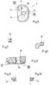
- ein Ausführungsbeispiel der erfindungsgemässenKniegelenkprothese in Explosionsdarstellung,
- Fig. 2
- eine Seitenansicht des Zapfens desAusführungsbeispiels der Kniegelenkprothesegemäss Fig. 1,
- Fig. 3
- einen Längsschnitt durch den Zapfen,
- Fig. 4
- die Einzelheit IV der Fig. 3,
- Fig. 5
- eine Aufsicht auf das Tibiateil desAusführungsbeispiels der Kniegelenkprothesegemäss Fig. 1,
- Fig. 6
- die Einzelheit VI der Fig. 5 (anteriorerVorsprung),
- Fig. 7
- die Einzelheit VII der Fig. 5 (posteriorerVorsprung)
- Fig. 8
- das Meniskusteil des Ausführungsbeispiels derKniegelenkprothese gemäss Fig. 1,
- Fig. 9
- die Einzelheit IX der Fig. 8 (anteriorerVorsprung)
- Fig. 10
- die Einzelheit X der Fig. 8 (posteriorerVorsprung).
- Fig. 1
- an embodiment of the inventive knee joint prosthesis in an exploded view,
- Fig. 2
- 2 shows a side view of the pin of the exemplary embodiment of the knee joint prosthesis according to FIG. 1,
- Fig. 3
- a longitudinal section through the pin,
- Fig. 4
- the detail IV of Fig. 3,
- Fig. 5
- 2 shows a top view of the tibia part of the exemplary embodiment of the knee joint prosthesis according to FIG. 1,
- Fig. 6
- the detail VI of Fig. 5 (anterior projection),
- Fig. 7
- detail VII of FIG. 5 (posterior projection)
- Fig. 8
- 1 shows the meniscus part of the exemplary embodiment of the knee joint prosthesis,
- Fig. 9
- the detail IX of Fig. 8 (anterior projection)
- Fig. 10
- the detail X of Fig. 8 (posterior projection).
Bei dem in Fig. 1 dargestellten Ausführungsbeispiel dererfindungsgemässen Kniegelenkprothese erkennt man einTibiateil 1, ein Femurteil 2, einen gemeinsamenLagerkörper in Form eines Meniskusteils 3, sowie einenZapfen 4. Anstelle des Meniskuksteils 3 können prinzipiell auch zwei separate Lagerschalen mitentsprechenden Lagerflächen vorgesehen sein.In the embodiment shown in Fig. 1One recognizes a knee joint prosthesis according to the
Das Tibiateil 1 weist auf seiner dem Femurteil 2 bzw. demMeniskusteil 3 zugewandten Fläche (Tibiaplateau) einegrossflächige Aussparung 10 auf, sodass ein umlaufenderRand 11 vorgesehen ist. An diesem umlaufenden Rand 11sind Mittel zum Befestigen des Meniskusteils 3vorgesehen. Dies sind der nach innen weisende Vorsprung12 im vorderen Bereich des umlaufenden Randes 11, sowieentsprechende nach innen weisende Vorsprünge im hinterenBereich, die in Fig. 1 mit den Bezugszeichen 13 und 14bezeichnet sind.The
Am Meniskusteil 3 sind entsprechende Vorsprüngevorgesehen, wobei in Fig. 1 nur die Vorsprünge 33 und 34zu erkennen sind. Zur Befestigung des Meniskusteils 3 amTibiateil 1 wird nun das Meniskusteil 3 in die Aussparung10 hineingeführt. Dies erfolgt z.B. derart, dass dieVorsprünge 33,34 des Meniskusteils 3 und dieentsprechenden Vorsprünge 13,14 des Tibiateils ineinandergreifen und dann der Vorsprung 32 am Meniskusteil 3 überden Vorsprung 12 am Tibiateil 1 gleitet, wodurch dasMeniskusteil 3 nach Art eines Schnappverschlusseseinschnappt. Somit ist das Meniskusteil 3 mit demTibiateil 1 fest verbunden, also relativ zum Tibiateil 1unbeweglich.Corresponding projections are on the meniscus part 3provided, only the
Das Meniskusteil 3 weist eine Öffnung 35 in Form einerDurchgangsbohrung auf. Durch diese Öffnung 35 hindurchkann der Zapfen 4 in eine Bohrung 15 im Tibiateil 1eingebracht werden. Der Zapfen 4 ist mit einemumlaufenden Vorsprung 40 versehen, welcher beimEinbringen des Zapfens 4 durch die Öffnung 35 desMeniskusteils 3 über einen entsprechenden Vorsprung 36 amMeniskusteil 3 gleitet, sodass anschliessend ein unbeabsichtigtes Herausgleiten des Zapfens 4 durch dieÖffnung 35 nicht mehr möglich ist.The meniscus part 3 has an
Ferner weist der Zapfen 4 ein Stabilisierungsstück 41auf, welches hier dem oberen Bereich des Zapfensentspricht. Dieses Stabilisierungsstück 41 undinsbesondere dessen Seitenflächen 410 bewirken imZusammenhang mit den Stabilisierungsflächen 210 amFemurteil 2 eine Varus/Valgus-Stabilisierung.Furthermore, the
Weiterhin ist im Stabilisierungsstück 41 des Zapfens 4eine nach unten offene Nut 411 vorgesehen. Ist dieProthese zusammengesetzt, greift in diese Nut 411 amStabilisierungsstück 41 des Zapfens 4 ein Steg 211 ein,der die Stabilisierungsflächen 210 des Femurteils 2miteinander-verbindet. Der Steg 211 erstreckt sich alsoin der interkondylären Nische bzw. im Falle einesinterkondylären Kastens im interkondylären Kasten, inwelchem er intergriert sein kann. Auf diese Art und Weiseist ein anteriorer und ein posteriorer Anschlagdefiniert, sodass ein unerwünschtes Abgleiten desFemurteils 2 in anteriorer oder posteriorer Richtungverhindert wird. Gleichzeitig ist eine gewisseFlexibilität des Femurteils 2 relativ zum Tibiateil 1bzw. relativ zum Meniskusteil 3 in axialer Richtunggewährleistet, weil der Zapfen 4 ja in axialer Richtungso lange beweglich ist, bis der Vorsprung 40 am Zapfen 4an dem entsprechenden Vorsprung des Meniskusteils 3anschlägt, damit der Zapfen 4 nicht unbeabsichtigt durchdie Öffnung 35 herausgleiten kann.Furthermore, in the stabilizing
Es ist also einerseits ein unbeabsichtigtes Herausgleitendes Zapfens 4 zuverlässig vermieden, gleichzeitig isteine Flexibilität des Femurteils 2 relativ zum Tibiateil1 bzw. relativ zum Meniskusteil 3 in axialer Richtunggegeben. Da der Zapfen 4 in der Bohrung 15 des Tibiateils 1 drehbar gelagert ist und sich der Zapfen 4 auch in derÖffnung 35 des Meniskusteils 3 drehen kann, ist imZustand der Flexion eine gewisse Drehung des Femurteils 2relativ zum Tibiateil 1 bzw. relativ zum Meniskusteil 3möglich. Im Zustand der Extension ist eine solche Drehungdes Femurteils 2 relativ zum Tibiateil 1 bzw. relativ zumMeniskusteil 3 aufgrund der hohen Kongruenz der Kondylen21 und der Lagerflächen 31 des Meniskusteils 3 nichtmöglich.So on the one hand it is an unintentional sliding outof the
Es soll noch darauf hingewiesen werden, dass dasTibiateil 1 und auch das Femurteil 2 Ansatzstücke 16 bzw.26 aufweisen, welche jeweils mit einem Verankerungsschaft17 bzw. 27 verbindbar ist, beispielsweise mittels einerkonischen Verbindung. Dadurch wird erreicht, dassnotfalls sogar noch während der Operation, im Normalfallaber bereits davor, die für den jeweiligen Patientenoptimalen Komponenten praktisch nach Art eines Bausatzeszusamnengestellt werden können, somit der Patient mit deroptimal auf ihn zugeschnittenen Prothese versorgt werdenkann.It should be pointed out that the
Fig. 2 zeigt eine Seitenansicht des Zapfens 4, auswelcher die Kontur der nach unten offenen Nut 411 guterkennbar ist. Die Nut weist an verschiedenen Stelleneinen Radius R auf, der etwa dem Radius des Stegs 211(Fig.1) entspricht, welcher die beiden Kondylenverbindet. Dies hat beim Beugen des Knies eine hoheKongruenz zur Folge, was die Flächenpressung (Druck)verringert und somit einen geringen Flexionswiderstandzur Folge hat, vereinfacht gesprochen lässt sich das Knievergleichsweise leicht beugen.Fig. 2 shows a side view of the
Fig. 3 zeigt einen Längsschnitt durch den Zapfen 4, auswelchem erkennbar ist, dass er eine Grube 42 für diePatella (Kniescheibe) aufweist, in welcher diese beim Beugen und Strecken des Knies gleiten kann. Ferner ist inFig. 3 noch die Einzelheit IV angedeutet, die in Fig. 4vergrössert dargestellt ist.Fig. 3 shows a longitudinal section through the
In Fig. 4 erkennt man diese Einzelheit, bei der es sichum den bereits früher erwähnten umlaufenden Vorsprung 40handelt, der im Zusammenwirken mit einem entsprechendenVorsprung 36 am Meniskusteil 3 derart zusammenwirkt, dassein unbeabsichtigtes Herausgleiten des Zapfens 4 durchdie Öffnung 35 des Meniskusteils 3 vermieden wird.4 shows this detail, which isaround the
Fig. 5 zeigt eine Aufsicht auf das Tibiateil 1, aus dernoch einmal die Vertiefung 10, der umlaufende Rand 11sowie die Vorsprünge 12,13,14 erkennbar sind. Bessererkennbar ist der anteriore Vorsprung 12 noch in Fig. 6,welche eine Schnittdarstellung der Einzelheit VI, alsoeinen Schnitt durch diesen Vorsprung 12, zeigt. Fig. 7zeigt eine entsprechende Schnittdarstellung derEinzelheit VII, also eine Schnittdarstellung desposterioren Vorsprungs 13, der posteriore Vorsprung 14entspricht diesem Vorsprung 13.Fig. 5 shows a plan view of the
Fig. 8 zeigt einen Schnitt durch das Meniskusteil 3 mitden Einzelheiten IX und X, wobei die Einzelheit IX, alsoder Vorsprung 32, in Fig. 9 und die Einzelheit X, alsoder Vorsprung 33 (der Vorsprung 34 ist analogausgebildet) in Fig. 10 noch einmal vergrössertdargestellt sind. Das Meniskusteil 3 bzw. dessenVorsprünge 33,34 könnnen hinter die entsprechendenVorsprünge 13,13 am Tibiateil 1 gleiten undanschliessend kann der Vorsprung 32 des Meniskusteils 3über den Vorsprung 12 am Tibiateil 1 gleiten undeinschnappen. Das Meniskusteil ist dann unbeweglich mitdem Tibiateil 1 verbunden.8 shows a section through the meniscus part 3 withthe details IX and X, the detail IX, that isthe
Die Lagerflächen 31 des Meniskusteils 3 sind, wie bereitserwähnt, so ausgebildet, dass im Zustand der Extension,also bei gestrecktem Knie, eine hohe Kongruenz vonLagerflächen 31 und den Kondylen 21 des Femurteils 2besteht. Eine Drehung des Femurteils 2 relativ zumTibiateil 1 bzw. relativ zum Meniskusteil 3 ist in diesemZustand im Prinzip nicht möglich. Im Zustand der Flexionhingegen, also bei gebeugtem Knie, erlaubt die geringereKongruenz eine Drehung des Femurteils 2 relativ zumTibiateil 1 bzw. zum Meniskusteil 3, weil der Zapfen 4drehbar gelagert ist. Gleichzeitig bleibt dieVarus/Valgus-Stabilisierung erhalten.The bearing surfaces 31 of the meniscus part 3 are, as alreadymentioned, designed so that in the state of the extension,with the knee extended, a high congruence ofBearing surfaces 31 and the
Claims (8)
Translated fromGermanPriority Applications (1)
| Application Number | Priority Date | Filing Date | Title |
|---|---|---|---|
| EP97811002AEP0923916A1 (en) | 1997-12-19 | 1997-12-19 | Knee joint prosthesis |
Applications Claiming Priority (1)
| Application Number | Priority Date | Filing Date | Title |
|---|---|---|---|
| EP97811002AEP0923916A1 (en) | 1997-12-19 | 1997-12-19 | Knee joint prosthesis |
Publications (1)
| Publication Number | Publication Date |
|---|---|
| EP0923916A1true EP0923916A1 (en) | 1999-06-23 |
Family
ID=8230534
Family Applications (1)
| Application Number | Title | Priority Date | Filing Date |
|---|---|---|---|
| EP97811002AWithdrawnEP0923916A1 (en) | 1997-12-19 | 1997-12-19 | Knee joint prosthesis |
Country Status (1)
| Country | Link |
|---|---|
| EP (1) | EP0923916A1 (en) |
Cited By (21)
| Publication number | Priority date | Publication date | Assignee | Title |
|---|---|---|---|---|
| EP1086667A1 (en) | 1999-09-24 | 2001-03-28 | Sulzer Orthopedics Ltd. | Tibial element for a knee prothesis and modular set comprising this tibial element |
| EP1470800A1 (en)* | 2003-04-24 | 2004-10-27 | Aesculap S.A.S. | Modular guide post for knee prothesis with posterior stabilisation. |
| DE102005022584A1 (en)* | 2005-05-09 | 2006-11-23 | Aesculap Ag & Co. Kg | Total prosthetic replacement for knee area, comprises specific arrangement of elements and motion limiting stops for femur part |
| US7326252B2 (en) | 2002-12-20 | 2008-02-05 | Smith & Nephew, Inc. | High performance knee prostheses |
| FR2913591A1 (en)* | 2007-03-15 | 2008-09-19 | C2F Implant Sarl | Posterior stabilized type complete knee prosthesis, has femoral condyles of femoral implant and glenoid surfaces corresponding to intermediate plateau are such that medial lobe engages in round cavity during flexion movement of joint |
| US7935151B2 (en) | 2001-03-05 | 2011-05-03 | Hudson Surgical Design, Inc. | Femoral prosthetic implant |
| US7967822B2 (en) | 1994-09-02 | 2011-06-28 | Hudson Surgical Design, Inc. | Methods and apparatus for orthopedic implants |
| US8021368B2 (en) | 2004-01-14 | 2011-09-20 | Hudson Surgical Design, Inc. | Methods and apparatus for improved cutting tools for resection |
| US8114083B2 (en) | 2004-01-14 | 2012-02-14 | Hudson Surgical Design, Inc. | Methods and apparatus for improved drilling and milling tools for resection |
| US8268006B2 (en) | 2001-01-29 | 2012-09-18 | Zimmer, Inc. | Constrained prosthetic knee with rotating bearing |
| US8287545B2 (en) | 2004-01-14 | 2012-10-16 | Hudson Surgical Design, Inc. | Methods and apparatus for enhanced retention of prosthetic implants |
| USRE44476E1 (en) | 2001-01-29 | 2013-09-03 | Zimmer, Inc. | Constrained prosthetic knee with rotating bearing |
| US8603095B2 (en) | 1994-09-02 | 2013-12-10 | Puget Bio Ventures LLC | Apparatuses for femoral and tibial resection |
| US8740906B2 (en) | 2004-01-14 | 2014-06-03 | Hudson Surgical Design, Inc. | Method and apparatus for wireplasty bone resection |
| US8926709B2 (en) | 2010-08-12 | 2015-01-06 | Smith & Nephew, Inc. | Structures for use in orthopaedic implant fixation and methods of installation onto a bone |
| DE102014106012B3 (en)* | 2014-04-29 | 2015-05-21 | Aesculap Ag | Knee endoprosthesis |
| DE102014204326A1 (en) | 2014-03-10 | 2015-09-10 | Waldemar Link Gmbh & Co. Kg | Connecting device for connecting two prosthesis parts and set with such a connection device and two prosthesis parts |
| US9642711B2 (en) | 2003-10-17 | 2017-05-09 | Smith & Nephew, Inc. | High flexion articular insert |
| US9730799B2 (en) | 2006-06-30 | 2017-08-15 | Smith & Nephew, Inc. | Anatomical motion hinged prosthesis |
| US10682236B2 (en) | 2015-11-06 | 2020-06-16 | Aesculap Ag | Knee joint endoprosthesis |
| CN112618114A (en)* | 2020-11-27 | 2021-04-09 | 北京市春立正达医疗器械股份有限公司 | Tantalum metal trabecular femoral condyle prosthesis and knee joint replacement body |
Citations (7)
| Publication number | Priority date | Publication date | Assignee | Title |
|---|---|---|---|---|
| DE2933124A1 (en) | 1978-10-06 | 1980-04-10 | Sulzer Ag | ENDOPROTHESIS FOR A KNEE JOINT |
| EP0194326A1 (en)* | 1983-09-23 | 1986-09-17 | orthoplant Endoprothetik GmbH | Knee-joint endoprosthesis |
| FR2601873A1 (en)* | 1986-07-25 | 1988-01-29 | Cuilleron J | Intracondylar total knee prosthesis |
| DE4102509A1 (en)* | 1991-01-29 | 1992-07-30 | Peter Brehm | Knee-joint prosthesis - where femur part has bearing housing with two-part plastic bearing insert in which connecting rod can pivot but not rotate |
| US5282867A (en)* | 1992-05-29 | 1994-02-01 | Mikhail Michael W E | Prosthetic knee joint |
| DE4434806A1 (en)* | 1994-09-29 | 1996-04-04 | Peter Brehm | Prosthesis for knee joints |
| EP0791343A2 (en)* | 1996-02-21 | 1997-08-27 | Plus Endoprothetik Ag | Knee joint endoprosthesis |
- 1997
- 1997-12-19EPEP97811002Apatent/EP0923916A1/ennot_activeWithdrawn
Patent Citations (7)
| Publication number | Priority date | Publication date | Assignee | Title |
|---|---|---|---|---|
| DE2933124A1 (en) | 1978-10-06 | 1980-04-10 | Sulzer Ag | ENDOPROTHESIS FOR A KNEE JOINT |
| EP0194326A1 (en)* | 1983-09-23 | 1986-09-17 | orthoplant Endoprothetik GmbH | Knee-joint endoprosthesis |
| FR2601873A1 (en)* | 1986-07-25 | 1988-01-29 | Cuilleron J | Intracondylar total knee prosthesis |
| DE4102509A1 (en)* | 1991-01-29 | 1992-07-30 | Peter Brehm | Knee-joint prosthesis - where femur part has bearing housing with two-part plastic bearing insert in which connecting rod can pivot but not rotate |
| US5282867A (en)* | 1992-05-29 | 1994-02-01 | Mikhail Michael W E | Prosthetic knee joint |
| DE4434806A1 (en)* | 1994-09-29 | 1996-04-04 | Peter Brehm | Prosthesis for knee joints |
| EP0791343A2 (en)* | 1996-02-21 | 1997-08-27 | Plus Endoprothetik Ag | Knee joint endoprosthesis |
Cited By (59)
| Publication number | Priority date | Publication date | Assignee | Title |
|---|---|---|---|---|
| US7967822B2 (en) | 1994-09-02 | 2011-06-28 | Hudson Surgical Design, Inc. | Methods and apparatus for orthopedic implants |
| US9066804B2 (en) | 1994-09-02 | 2015-06-30 | Puget Bioventures Llc | Method and apparatus for femoral and tibial resection |
| US8603095B2 (en) | 1994-09-02 | 2013-12-10 | Puget Bio Ventures LLC | Apparatuses for femoral and tibial resection |
| EP1086667A1 (en) | 1999-09-24 | 2001-03-28 | Sulzer Orthopedics Ltd. | Tibial element for a knee prothesis and modular set comprising this tibial element |
| EP2272469B1 (en) | 2001-01-29 | 2015-07-01 | Zimmer GmbH | Constrained prosthetic knee with rotating bearing |
| US8888857B2 (en) | 2001-01-29 | 2014-11-18 | Zimmer, Inc. | Constrained prosthetic knee with rotating bearing |
| USRE44476E1 (en) | 2001-01-29 | 2013-09-03 | Zimmer, Inc. | Constrained prosthetic knee with rotating bearing |
| US8268006B2 (en) | 2001-01-29 | 2012-09-18 | Zimmer, Inc. | Constrained prosthetic knee with rotating bearing |
| US8088167B2 (en) | 2001-03-05 | 2012-01-03 | Hudson Surgical Design, Inc. | Femoral prosthetic implant |
| US7935151B2 (en) | 2001-03-05 | 2011-05-03 | Hudson Surgical Design, Inc. | Femoral prosthetic implant |
| US9192391B2 (en) | 2001-03-05 | 2015-11-24 | Puget Bioventures Llc | Method for minimally invasive total knee arthroplasty |
| US8430932B2 (en) | 2001-03-05 | 2013-04-30 | Puget Bio Ventures LLC | Femoral prosthetic implant |
| US8062377B2 (en) | 2001-03-05 | 2011-11-22 | Hudson Surgical Design, Inc. | Methods and apparatus for knee arthroplasty |
| US9421022B2 (en) | 2001-03-05 | 2016-08-23 | Puget Bioventures Llc | Method and apparatus for total knee arthroplasty |
| US8398716B2 (en) | 2002-12-20 | 2013-03-19 | Smith & Nephew, Inc. | High performance knee prostheses with posterior cam |
| US8403992B2 (en) | 2002-12-20 | 2013-03-26 | Smith & Nephew, Inc. | High performance knee prostheses |
| US9707087B2 (en) | 2002-12-20 | 2017-07-18 | Smith & Nephew, Inc. | High performance knee prosthesis |
| US10149768B2 (en) | 2002-12-20 | 2018-12-11 | Smith & Nephew, Inc. | High performance knee prostheses |
| US9402729B2 (en) | 2002-12-20 | 2016-08-02 | Smith & Nephew, Inc. | High performance knee prostheses |
| US8394148B2 (en) | 2002-12-20 | 2013-03-12 | Smith & Nephew, Inc. | Tibial component of high performance knee prosthesis |
| US8394147B2 (en) | 2002-12-20 | 2013-03-12 | Smith & Nephew, Inc. | High performance femoral knee prostheses |
| US8652210B2 (en) | 2002-12-20 | 2014-02-18 | Smith & Nephew, Inc. | Femoral prostheses with lateral buttress for patella |
| US8398715B2 (en) | 2002-12-20 | 2013-03-19 | Smith & Nephew, Inc. | High performance knee prostheses with converging anterior and posterior portions |
| US7326252B2 (en) | 2002-12-20 | 2008-02-05 | Smith & Nephew, Inc. | High performance knee prostheses |
| US8425617B2 (en) | 2002-12-20 | 2013-04-23 | Smith & Nephew, Inc. | Knee prostheses with convex slope on portion of tibial articular surface |
| US11369477B2 (en) | 2002-12-20 | 2022-06-28 | Smith & Nephew, Inc. | High performance knee prostheses |
| US8449618B2 (en) | 2002-12-20 | 2013-05-28 | Smith & Nephew, Inc. | High performance knee prostheses |
| US9320605B2 (en) | 2002-12-20 | 2016-04-26 | Smith & Nephew, Inc. | High performance knee prostheses |
| US7922771B2 (en) | 2002-12-20 | 2011-04-12 | Smith & Nephew, Inc. | High performance knee prostheses |
| US8603178B2 (en) | 2002-12-20 | 2013-12-10 | Smith & Nephew, Inc. | Knee prostheses with convex portion on tibial lateral articular surface |
| US8647389B2 (en) | 2002-12-20 | 2014-02-11 | Smith & Nephew, Inc. | High performance knee prostheses |
| FR2854059A1 (en)* | 2003-04-24 | 2004-10-29 | Aesculap Sa | MODULAR PLOT FOR POSTERO-STABILIZED KNEE PROSTHESIS |
| EP1470800A1 (en)* | 2003-04-24 | 2004-10-27 | Aesculap S.A.S. | Modular guide post for knee prothesis with posterior stabilisation. |
| JP2004321794A (en)* | 2003-04-24 | 2004-11-18 | Aesculap | Modular stud of artificial knee with stabilized rear part |
| US9642711B2 (en) | 2003-10-17 | 2017-05-09 | Smith & Nephew, Inc. | High flexion articular insert |
| US8021368B2 (en) | 2004-01-14 | 2011-09-20 | Hudson Surgical Design, Inc. | Methods and apparatus for improved cutting tools for resection |
| US8740906B2 (en) | 2004-01-14 | 2014-06-03 | Hudson Surgical Design, Inc. | Method and apparatus for wireplasty bone resection |
| US9814539B2 (en) | 2004-01-14 | 2017-11-14 | Puget Bioventures Llc | Methods and apparatus for conformable prosthetic implants |
| US8114083B2 (en) | 2004-01-14 | 2012-02-14 | Hudson Surgical Design, Inc. | Methods and apparatus for improved drilling and milling tools for resection |
| US8287545B2 (en) | 2004-01-14 | 2012-10-16 | Hudson Surgical Design, Inc. | Methods and apparatus for enhanced retention of prosthetic implants |
| US8298238B2 (en) | 2004-01-14 | 2012-10-30 | Hudson Surgical Design, Inc. | Methods and apparatus for pivotable guide surfaces for arthroplasty |
| US8353914B2 (en) | 2004-02-02 | 2013-01-15 | Hudson Surgical Design, Inc. | Methods and apparatus for improved profile based resection |
| DE102005022584A1 (en)* | 2005-05-09 | 2006-11-23 | Aesculap Ag & Co. Kg | Total prosthetic replacement for knee area, comprises specific arrangement of elements and motion limiting stops for femur part |
| DE102005022584B4 (en)* | 2005-05-09 | 2007-03-08 | Aesculap Ag & Co. Kg | Coupled knee endoprosthesis |
| US9730799B2 (en) | 2006-06-30 | 2017-08-15 | Smith & Nephew, Inc. | Anatomical motion hinged prosthesis |
| US12383405B2 (en) | 2006-06-30 | 2025-08-12 | Smith & Nephew, Inc. | Anatomical motion hinged prosthesis |
| US10779949B2 (en) | 2006-06-30 | 2020-09-22 | Smith & Nephew, Inc. | Anatomical motion hinged prosthesis |
| FR2913591A1 (en)* | 2007-03-15 | 2008-09-19 | C2F Implant Sarl | Posterior stabilized type complete knee prosthesis, has femoral condyles of femoral implant and glenoid surfaces corresponding to intermediate plateau are such that medial lobe engages in round cavity during flexion movement of joint |
| US8926709B2 (en) | 2010-08-12 | 2015-01-06 | Smith & Nephew, Inc. | Structures for use in orthopaedic implant fixation and methods of installation onto a bone |
| DE102014204326A1 (en) | 2014-03-10 | 2015-09-10 | Waldemar Link Gmbh & Co. Kg | Connecting device for connecting two prosthesis parts and set with such a connection device and two prosthesis parts |
| WO2015135762A1 (en)* | 2014-03-10 | 2015-09-17 | Waldemar Link Gmbh & Co. Kg | Connection device for connecting two prosthesis parts, and kit with one such connection device and two prosthesis parts |
| CN106163456B (en)* | 2014-03-10 | 2018-12-28 | 沃尔德马连接两合公司 | For connecting the attachment device in two prosthese portions and the external member with a this attachment device and two prosthese portions |
| US10568748B2 (en) | 2014-03-10 | 2020-02-25 | Waldemar Link Gmbh & Co. Kg | Connection device for connecting two prosthesis parts, and kit with one such connection device and two prosthesis parts |
| CN106163456A (en)* | 2014-03-10 | 2016-11-23 | 沃尔德马连接两合公司 | For connecting the attachment means in two prosthese portions and there is a this attachment means and the external member in two prosthese portions |
| DE102014106012B9 (en)* | 2014-04-29 | 2015-09-17 | Aesculap Ag | Knee endoprosthesis |
| US10070965B2 (en) | 2014-04-29 | 2018-09-11 | Aesculap Ag | Knee joint endoprosthesis |
| DE102014106012B3 (en)* | 2014-04-29 | 2015-05-21 | Aesculap Ag | Knee endoprosthesis |
| US10682236B2 (en) | 2015-11-06 | 2020-06-16 | Aesculap Ag | Knee joint endoprosthesis |
| CN112618114A (en)* | 2020-11-27 | 2021-04-09 | 北京市春立正达医疗器械股份有限公司 | Tantalum metal trabecular femoral condyle prosthesis and knee joint replacement body |
Similar Documents
| Publication | Publication Date | Title |
|---|---|---|
| EP0913132B1 (en) | Knee prosthesis | |
| EP0923916A1 (en) | Knee joint prosthesis | |
| EP0791344B1 (en) | Knee joint endoprosthesis | |
| DE69220358T2 (en) | Bearing combination with rotating and sliding movement in a biological joint replacement | |
| DE3138848C2 (en) | Endoprosthesis to replace a rod-shaped bone | |
| DE60018523T2 (en) | Tibial part of a knee prosthesis with a mobile bearing | |
| DE69516639T2 (en) | Modular knee prosthesis | |
| DE69833736T2 (en) | Rotatable joint prosthesis with axial fixation | |
| DE69832861T2 (en) | Joint prosthesis system with a longitudinally sealed rotatable component | |
| DE4102509C2 (en) | Knee joint endoprosthesis | |
| DE69518077T3 (en) | CUTTER FOR THE FEMORAL INTERCONDYLARINE GROOVE OF A KNEE PROSTHESIS STABILIZED FROM THE BACK | |
| DE102007032150B4 (en) | Artificial meniscus part and knee joint prosthesis | |
| DE3013155A1 (en) | TIBIA PROSTHESIS | |
| DE8901097U1 (en) | Prosthetic knee joint with improved guidance of the patellar component | |
| DE2304988A1 (en) | KNEE PROSTHESIS | |
| EP1658023A1 (en) | Ankle-joint endoprosthesis | |
| WO1999001090A1 (en) | Shankless knee joint endoprosthesis | |
| DE2320683A1 (en) | ENDOPROSTHESIS FOR THE PROXIMAL HIP PART | |
| DE2122390B2 (en) | KNEE JOINT ENDOPROTHESIS | |
| DE69220779T2 (en) | "Backward stabilized total knee prosthesis" | |
| DE69815789T2 (en) | End-of-knee prosthesis with improved posterior stability and measures to prevent dislocation | |
| DE3205577A1 (en) | BONE PROSTHESIS | |
| DE2901009A1 (en) | Internal artificial knee joint - has insert piece joined to dish by guide ensuring smooth sliding movement | |
| WO2004096102A1 (en) | Knee joint prosthesis | |
| DE69111387T2 (en) | PROSTHETIC KNEE JOINT. |
Legal Events
| Date | Code | Title | Description |
|---|---|---|---|
| PUAI | Public reference made under article 153(3) epc to a published international application that has entered the european phase | Free format text:ORIGINAL CODE: 0009012 | |
| AK | Designated contracting states | Kind code of ref document:A1 Designated state(s):AT BE CH DE DK ES LI | |
| AX | Request for extension of the european patent | Free format text:AL;LT;LV;MK;RO;SI | |
| 17P | Request for examination filed | Effective date:19991125 | |
| AKX | Designation fees paid | Free format text:AT BE CH DE DK ES LI | |
| RBV | Designated contracting states (corrected) | Designated state(s):AT CH DE FR GB IT LI | |
| 17Q | First examination report despatched | Effective date:20030107 | |
| STAA | Information on the status of an ep patent application or granted ep patent | Free format text:STATUS: THE APPLICATION IS DEEMED TO BE WITHDRAWN | |
| 18D | Application deemed to be withdrawn | Effective date:20030520 |