EP0921694B1 - Stereoscopic image pick-up apparatus - Google Patents
Stereoscopic image pick-up apparatusDownload PDFInfo
- Publication number
- EP0921694B1 EP0921694B1EP98122894AEP98122894AEP0921694B1EP 0921694 B1EP0921694 B1EP 0921694B1EP 98122894 AEP98122894 AEP 98122894AEP 98122894 AEP98122894 AEP 98122894AEP 0921694 B1EP0921694 B1EP 0921694B1
- Authority
- EP
- European Patent Office
- Prior art keywords
- image
- image pick
- distance
- point
- sight
- Prior art date
- Legal status (The legal status is an assumption and is not a legal conclusion. Google has not performed a legal analysis and makes no representation as to the accuracy of the status listed.)
- Expired - Lifetime
Links
- 230000003287optical effectEffects0.000claimsdescription46
- 210000001508eyeAnatomy0.000claimsdescription41
- 239000013598vectorSubstances0.000claimsdescription31
- 238000000034methodMethods0.000claimsdescription28
- 238000001514detection methodMethods0.000claimsdescription11
- 230000004044responseEffects0.000claimsdescription3
- 230000009466transformationEffects0.000claimsdescription3
- 238000001444catalytic combustion detectionMethods0.000description19
- 230000004927fusionEffects0.000description17
- 238000010586diagramMethods0.000description12
- 210000005252bulbus oculiAnatomy0.000description8
- 239000004973liquid crystal related substanceSubstances0.000description6
- 230000008569processEffects0.000description5
- 238000004519manufacturing processMethods0.000description3
- 238000010276constructionMethods0.000description2
- 230000006870functionEffects0.000description2
- 230000004048modificationEffects0.000description2
- 238000012986modificationMethods0.000description2
- 210000001525retinaAnatomy0.000description2
- 241000282412HomoSpecies0.000description1
- 230000008033biological extinctionEffects0.000description1
- 238000006243chemical reactionMethods0.000description1
- 210000004087corneaAnatomy0.000description1
- 238000011157data evaluationMethods0.000description1
- 230000000694effectsEffects0.000description1
- 210000003128headAnatomy0.000description1
- 230000001678irradiating effectEffects0.000description1
- 230000007246mechanismEffects0.000description1
- 230000008447perceptionEffects0.000description1
- 210000001747pupilAnatomy0.000description1
- 230000002207retinal effectEffects0.000description1
- 210000003786scleraAnatomy0.000description1
- 230000000007visual effectEffects0.000description1
Images


Classifications
- H—ELECTRICITY
- H04—ELECTRIC COMMUNICATION TECHNIQUE
- H04N—PICTORIAL COMMUNICATION, e.g. TELEVISION
- H04N13/00—Stereoscopic video systems; Multi-view video systems; Details thereof
- H04N13/30—Image reproducers
- H04N13/398—Synchronisation thereof; Control thereof
- H—ELECTRICITY
- H04—ELECTRIC COMMUNICATION TECHNIQUE
- H04N—PICTORIAL COMMUNICATION, e.g. TELEVISION
- H04N13/00—Stereoscopic video systems; Multi-view video systems; Details thereof
- H04N13/20—Image signal generators
- H04N13/204—Image signal generators using stereoscopic image cameras
- H04N13/239—Image signal generators using stereoscopic image cameras using two 2D image sensors having a relative position equal to or related to the interocular distance
- H—ELECTRICITY
- H04—ELECTRIC COMMUNICATION TECHNIQUE
- H04N—PICTORIAL COMMUNICATION, e.g. TELEVISION
- H04N13/00—Stereoscopic video systems; Multi-view video systems; Details thereof
- H04N13/20—Image signal generators
- H04N13/204—Image signal generators using stereoscopic image cameras
- H04N13/246—Calibration of cameras
- H—ELECTRICITY
- H04—ELECTRIC COMMUNICATION TECHNIQUE
- H04N—PICTORIAL COMMUNICATION, e.g. TELEVISION
- H04N13/00—Stereoscopic video systems; Multi-view video systems; Details thereof
- H04N13/20—Image signal generators
- H04N13/257—Colour aspects
- H—ELECTRICITY
- H04—ELECTRIC COMMUNICATION TECHNIQUE
- H04N—PICTORIAL COMMUNICATION, e.g. TELEVISION
- H04N13/00—Stereoscopic video systems; Multi-view video systems; Details thereof
- H04N13/30—Image reproducers
- H04N13/366—Image reproducers using viewer tracking
- H04N13/383—Image reproducers using viewer tracking for tracking with gaze detection, i.e. detecting the lines of sight of the viewer's eyes
- H—ELECTRICITY
- H04—ELECTRIC COMMUNICATION TECHNIQUE
- H04N—PICTORIAL COMMUNICATION, e.g. TELEVISION
- H04N13/00—Stereoscopic video systems; Multi-view video systems; Details thereof
- H04N13/10—Processing, recording or transmission of stereoscopic or multi-view image signals
- H04N13/189—Recording image signals; Reproducing recorded image signals
- H—ELECTRICITY
- H04—ELECTRIC COMMUNICATION TECHNIQUE
- H04N—PICTORIAL COMMUNICATION, e.g. TELEVISION
- H04N13/00—Stereoscopic video systems; Multi-view video systems; Details thereof
- H04N13/20—Image signal generators
- H04N13/204—Image signal generators using stereoscopic image cameras
- H04N13/207—Image signal generators using stereoscopic image cameras using a single 2D image sensor
- H04N13/211—Image signal generators using stereoscopic image cameras using a single 2D image sensor using temporal multiplexing
- H—ELECTRICITY
- H04—ELECTRIC COMMUNICATION TECHNIQUE
- H04N—PICTORIAL COMMUNICATION, e.g. TELEVISION
- H04N13/00—Stereoscopic video systems; Multi-view video systems; Details thereof
- H04N13/20—Image signal generators
- H04N13/296—Synchronisation thereof; Control thereof
- H—ELECTRICITY
- H04—ELECTRIC COMMUNICATION TECHNIQUE
- H04N—PICTORIAL COMMUNICATION, e.g. TELEVISION
- H04N13/00—Stereoscopic video systems; Multi-view video systems; Details thereof
- H04N13/30—Image reproducers
- H04N13/302—Image reproducers for viewing without the aid of special glasses, i.e. using autostereoscopic displays
- H04N13/305—Image reproducers for viewing without the aid of special glasses, i.e. using autostereoscopic displays using lenticular lenses, e.g. arrangements of cylindrical lenses
- H—ELECTRICITY
- H04—ELECTRIC COMMUNICATION TECHNIQUE
- H04N—PICTORIAL COMMUNICATION, e.g. TELEVISION
- H04N13/00—Stereoscopic video systems; Multi-view video systems; Details thereof
- H04N13/30—Image reproducers
- H04N13/302—Image reproducers for viewing without the aid of special glasses, i.e. using autostereoscopic displays
- H04N13/31—Image reproducers for viewing without the aid of special glasses, i.e. using autostereoscopic displays using parallax barriers
- H—ELECTRICITY
- H04—ELECTRIC COMMUNICATION TECHNIQUE
- H04N—PICTORIAL COMMUNICATION, e.g. TELEVISION
- H04N13/00—Stereoscopic video systems; Multi-view video systems; Details thereof
- H04N13/30—Image reproducers
- H04N13/332—Displays for viewing with the aid of special glasses or head-mounted displays [HMD]
- H04N13/341—Displays for viewing with the aid of special glasses or head-mounted displays [HMD] using temporal multiplexing
- H—ELECTRICITY
- H04—ELECTRIC COMMUNICATION TECHNIQUE
- H04N—PICTORIAL COMMUNICATION, e.g. TELEVISION
- H04N13/00—Stereoscopic video systems; Multi-view video systems; Details thereof
- H04N13/30—Image reproducers
- H04N13/332—Displays for viewing with the aid of special glasses or head-mounted displays [HMD]
- H04N13/344—Displays for viewing with the aid of special glasses or head-mounted displays [HMD] with head-mounted left-right displays
- H—ELECTRICITY
- H04—ELECTRIC COMMUNICATION TECHNIQUE
- H04N—PICTORIAL COMMUNICATION, e.g. TELEVISION
- H04N13/00—Stereoscopic video systems; Multi-view video systems; Details thereof
- H04N2013/0074—Stereoscopic image analysis
- H04N2013/0081—Depth or disparity estimation from stereoscopic image signals
Definitions
- the present inventionrelates to an image pick-up apparatus for stereoscope for picking up parallax images for stereoscopic viewing. More particularly, the present invention relates to an image pick-up apparatus for picking up, without user intervention, parallax images that satisfy binocular fusion conditions and an image pick-up apparatus that lets a user know whether the binocular fusion conditions are satisfied.
- Some known stereoscopic image pick-up apparatusescapture parallax images from a plurality of view points using a plurality of cameras.
- a plurality of camerasare mounted on tripod heads, and a user manually adjusts a spacing and a convergence angle between camera axes, based on his or her operational experience, depending on a scene to be captured, and image-captures the scene while actually observing the stereoscopic view on a monitor.
- Head-mounted displays and eyeglass-type displayshave been developed today, and these displays let an image for the right eye to be selectively presented on the right eye and an image for the left eye to be selectively presented on the left eye.
- a stereoscopic image producing a depth perceptionis thus observed.
- a liquid-crystal displayis combined with a lenticular sheet having a predetermined pitch or a mask with apertures and non-apertures formed in a predetermined pattern to impart a directivity to a light ray from the liquid-crystal display, and by making the directivity match the pattern of the image presented on the liquid-crystal display, the observer watches the image for the right eye on the right eye and the image for the left eye on the left eye. The observer thus enjoys the image presenting depth.
- the image presentedis typically acquired through a binocular-type camera having two lens sets.
- An apparatusdisclosed in Japanese Examined Patent Publication No. JP-A-8-27499 (telescopic television image pick-up apparatus), does not require two lens sets.
- This apparatusincludes two liquid-crystal shutters, a total reflection mirror and a half mirror and picks up alternately left and right parallax images through a single lens set.
- the adjustment of a parallax between left and right imagesnamely, the adjustment of convergence is required during image-capturing.
- the convergence adjustmentis typically manually performed.
- the above binocular-type cameraemploys two lens sets, one for forming the image for the right eye and the other for forming the image for the left eye, and the user feels fatigue when observing a stereoscopic image or cannot to attain image fusion at all, if performance differences due to manufacturing error (for example, in magnification, deviation in optical axis, tint, brightness, distortion, field tilt and the like) are present between the two lenses.
- manufacturing errorfor example, in magnification, deviation in optical axis, tint, brightness, distortion, field tilt and the like
- the accuracy of componentsneeds to be heightened. Adjustment is further required if the improved accuracy of components is still not sufficient enough.
- special meansis used, for example, images are electronically corrected.
- the zoom variator operations of the left and right lens setsmust be interlocked in a state with these performances factored in. This arrangement is costly and time consuming to manufacture, and is inadequate for mass production.
- the binocular-type cameraTo observe the images picked up by the binocular-type camera, two monitors are typically required. The use of the two monitors is not practical. To record the two images, a special recording device is needed to synchronize the one image to the other. Without using it, the conversion of two image signals into one image signal is contemplated. To convert the two image signals into one image signal, however, a special converter is required to alternately display and record the left and right parallax images. Compared with a single lens camera, the binocular-type camera itself is bulky. The entire system of the image pick-up apparatus, in need of the above-described special devices, fails to achieve widespread commercial acceptance among users because of its bulkier, costlier and less mobile design.
- the time-division camera proposed in the above-cited Japanese Examined Patent Publication No. JP-A-8-27499combines the optical paths for left and right parallax images at a half mirror into one optical path to guide images to a single lens. When images are transmitted through or reflected from the half mirror before entering the lens, the quantity of light is reduced to half or smaller.
- the arrangement disclosed in the above-cited Japanese Examined Patent Publication No. JP-A-8-27499theoretically presents a difference between the lengths of the optical paths of the left and right parallax images, suffering a magnification difference between the left and right images. This becomes a cause of the fatigue of the user when he or she observes the images picked-up, and as a result, the user cannot observe the images fused and cannot observe them in a stereoscopic view.
- document EP-A-0 641 132discloses a stereoscopic image pick-up and display apparatus, wherein two camera bodies each having an objective lens are operated and the output signals are further evaluated. A convergence control is performed so that the optical axes of the cameras converge at an optimum point to ensure that the parallax of the captured images comes within the binocular fusing range of a viewer.
- a parallax calculatoris provided for calculating the parallax of an image and the parallax of the nearest object is used for calculating the depth-wise position of an object to be reproduced at the nearest point when a captured image is displayed by the stereoscopic image display apparatus.
- the fusing rangeis defined on the depth display position calculator, and the converging angle is controlled in a manner that the object at the nearest point is positioned within the fusional range of the viewer. Furthermore, a line-of-sight detecting means is used for detecting the point on which the viewer's eye is focused.
- document JP-A-7 067 023discloses a multi-eye image pick-up apparatus with immediate image pick-up wherein a first and a second video camera portion are provided for picking up a stereoscopic image.
- the control meanssets the optical axes of the first and the second video camera portions at predetermined optical axis angles.
- the apparatuscomprises means for visual axis detection, thereby determining the position of the eyeball and, upon data evaluation, the viewing direction of the user.
- the present inventionprovides an image pick-up apparatus for capturing images for stereoscopic viewing, which comprises image pick-up means for picking up left and right parallax images of a main subject respectively for the left and right eyes, display means for displaying the left and right parallax images, picked up by the image pick-up means, line-of-sight detection means for detecting the lines of sight of the left and right eyes, looking the respective images displayed by the display means, and determining means for determining, based on the output of the line-of-sight detection means, whether the main subject falls within an image-fusible range.
- the apparatusdetects the lines of sight of an observer who observes the display means on which the left parallax image and right parallax image are presented, and, instead of the observer, determines, based on the lines of sight, whether the subject falls within the image-fusible range.
- the determination result provided by the determining meansis reported to the user.
- an image-fusible rangeis defined by the inter-pupillary distance and the distance of distinct vision of a user.
- the image date of the parallax imagesis stored in a memory in response to the output of the determining means.
- the line-of-sight detection meansfurther comprises converting means for converting the left and right lines of sight of a user into left and right direction vectors that are respectively expressed in left and right coordinate systems of the image pick-up means, and coordinates calculator means for calculating the coordinate values of the crossing point of the left and right direction vectors in the world coordinate system.
- the image-fusible rangeis expressed according to a farthest position and a nearest position from the view point of the user in the direction of depth.
- the farthest position of the image-fusible rangeis set to be a point so that the horizontal distance between two second points on the left and right image planes of the image pick-up means corresponding to a first point (A) of the farthest position is substantially equal to the inter-pupillary distance of the user.
- the nearest position of the image-fusible rangeis set to be a point so that a position (C') where two points on the left and right image planes of the image pick-up means corresponding to a first point (C) of the nearest position, through perspective transformation based on the left and right view points of the user, look standing out to the user, is approximately equal to the point at the distance of distinct vision of the user.
- FIG. 1is a block diagram showing the construction of a "stereoscopic image pick-up apparatus" according to a first embodiment of the present invention.
- the stereo camera 1for capturing a plurality of parallax images
- the stereo camera 1comprises a right optical system 101 for capturing a parallax image for the right eye and CCD 103 of a photoelectric converter and a left optical system 102 for capturing a parallax image for the left eye and CCD 104 of a photoelectric converter.
- the pair of optical system 101 and CCD 103is identical in optical specification to the pair of optical system 102 and CCD 104.
- the optical system 101 and CCD 103 and the optical system 102 and CCD 104are arranged so that the spacing between the two pairs (hereinafter referred to as a base line distance) and the angle made between the two pairs (hereinafter referred to as a convergence angle) are variably set with an unshown mechanism.
- the base line distance and the convergence angleare adjusted by a known convergence/base line distance adjuster 11.
- a convergence angle/base line distance detector 10detects the convergence angle and base line distance with its unshown encoder.
- FIG. 2shows the positions of the optical systems 101 and 102 relative to a main subject.
- ⁇ brepresent the convergence angle between the optical systems 101 and 102
- 2krepresent the base line distance.
- the adjuster 11adjusts the convergence angle ⁇ b and the base line distance 2k, and an adjusted angle is detected by the detector 10, and is then sent to a calculating unit 3 (FIG. 1) to be described later.
- An image display 2includes a right display unit 201 for the right eye, a left display unit 202 for the left eye, a right line-of-sight detector 203, and a left line-of-sight detector 204.
- the right display unit 201 and left display unit 202are identical in specification, and are the so-called retinal display that provides an image through the after image effect by irradiating and scanning the retina with a light beam from a liquid crystal, CRT, LED or laser, each equipped with an observation optical system.
- the display units 201 and 202respectively scan the left and right retinas by a light beam from an LED circuit 12 to give left and right stereoscopic images to the user.
- a right line-of-sight detector 203 and left line-of-sight detector 204. in image display 2employ the method of detecting the line of sight from the so-called corneal reflection light.
- the image display 2includes liquid-crystal displays LCD205 and LCD206. This method is disclosed in detail in Japanese Unexamined Patent Publication No. JP-A-5-68188, and the discussion of the method is omitted here.
- the line-of-sight information about the eyeball obtained by the line-of-sight detectors 203 and 204is sent to the calculating unit 3 to be described later, and serves as a basis for the calculation of the direction vector of the line of sight.
- the calculating unit 3 of the image pick-up apparatuscalculates an image-pickable range of the stereo camera 1 that assures that the left and right parallax images picked up by the stereo camera 1 causes an image fusion on the user (such a range is hereinafter referred to as "image-fusible range").
- the calculating unit 3substantially realized by computer software, is shown in a functional block diagram in FIG. 1, and comprises a right line-of-sight range calculator 301, a left line-of-sight range calculator 302, a line-of-sight vector calculator 303, a crossing point calculator 307, a distance calculator 305, an image-pickable range calculator 304, and a comparator 306.
- the two line-of-sight range calculators 301 and 302are respectively connected to the right line-of-sight detector 203 and the left line-of-sight detector 204, and calculate the line-of-sight ranges for the left and right eyes of the user based on the outputs from the two detectors 203 and 204.
- the left and right line-of-sight ranges calculatedare input to the line-of-sight vector calculator 303, which calculates the direction vectors of the left and right lines of sight ( d R and d L to be described later).
- the crossing point calculator 307determines the coordinates of the crossing point of the lines of sight, based on the detected direction vectors d R and d L of the lines of sight.
- the distance calculator 305calculates a distance 1 from the view point of the user to the subject, based on the detected direction vectors of the lines of sight.
- the image-pickable range calculator 304calculates the image-pickable range (namely, between the distal limit A of the range and the proximal limit B of the range in the direction of depth).
- the comparator 306compares the distance 1 to the subject, calculated by the distance calculator 305, to the limit values A and B, calculated by the image-pickable range calculator 304, to determine whether the subject meets an image fusion condition. Specifically, if the distance to the subject, calculated by the distance calculator 305, meets the following equation, B ⁇ l ⁇ A the subject is within the image-pickable range, and is determined to meet the image fusion condition.
- An image controller 4controls the units in the image pick-up apparatus. Specifically, the image controller 4 controls right and left camera processors 5 and 6, for the right and left eyes, which converts image signals from CCDs 103 and 104 into a predetermined image format. These processors 5 and 6, under the control of the image controller 4, convert the left and right parallax images picked up by the stereo camera 1 into the predetermined format and store them in an image memory 9.
- the images in the image memory 9are read and converted into video signals by the image controller 4, and the video signals are then sent to the display units 201 and 202 via drivers 7 and 8, respectively.
- the image controller 4exchanges data with the image memory 9.
- the image controller 4also sends to the LED circuit 12 a signal that controls the lighting and extinction of an unshown LED installed in the image display 2.
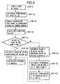
- FIG. 3shows the operation starting at the line-of-sight detectors 203 and 204 and ending with the calculating unit 3, particularly, to the process for determining the direction vectors of the lines of sight based on the data detected by the line-of-sight detectors 203 and 204.
- the subjectis picked-up using the stereo camera, and the parallax images in stereoscopic view are presented to the user using the display. Specifically, observing the left and right parallax images presented on the display, the observer indirectly looks at the subject. The image pick-up apparatus then detects the lines of sight of the observer's eyes.
- Step S1corresponds to the line-of-sight detectors 203 and 204 shown in FIG. 1
- steps S2 and S3correspond to the line-of-sight range detectors 301 and 302 shown in FIG. 1
- step S4corresponds to the line-of-sight vector calculator 303
- steps S5, S6, S8, S9 and S10correspond to the crossing point calculator 307
- step S7corresponds to the distance calculator 305.
- step S1the lines of sight, namely, the directions of rotation of the eyeballs are detected, based on the corneal reflection phenomenon.
- each of the line-of-sight detectors 203 and 204has its own LCD and CCD.
- LCD 205 and LCD 206irradiate the eyeballs of the observer by infrared light beams having a known pattern. The patterned beams are reflected by the corneas, and are then captured by CCD 207 and CCD 208 as images. Since LCD 205 and LCD 206 are beforehand respectively aligned with CCD 207 and CCD 208 in their respective coordinate systems, the pixel positions on CCD 207 and CCD 208 are considered to correspond to the respective spot positions on LCD 205 and LCD 206.
- step S2the coordinate values of each beam spot in each LCD coordinate system are determined. The coordinate values of the beam spot in each LCD coordinate system represent the angle of rotation of the respective eyeball.
- step S3the coordinate values of the beam spot in each LCD coordinate system obtained in step S2 are converted into the coordinate values in the coordinate systems of the stereo camera 1 (namely, the coordinate systems of CCD 103 and CCD 104).
- Step S4determines direction vectors d R and d L of straight lines that connect the coordinates of the left beat spot and right beam spot, expressed in the coordinate systems of the stereo camera 1, to reference points of the optical systems 101 and 102.
- the direction vectorsare lines of sight expressed in the world coordinate system.
- the line of sight expressed in the world coordinate systemis hereinafter referred to as "line-of-sight vector" or simply "direction vector".
- step S5determines whether the right direction vector d R and left direction vector d L are present the same plane.
- the controller 4goes to step S6 to calculate the crossing point (designated X) of the right direction vector d R and left direction vector d L in the world coordinate system.
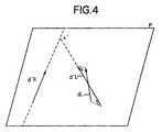
- step S8plane P in which the right direction vector d R and the reference point of the right optical system 101 lie is determined as shown in FIG. 4.
- step S9an orthogonal projection vector d L ' of the left direction vector d L with respect to the plane P is determined.
- step S10the coordinates of the crossing point (designated X') of the right direction vector d R and the left direction vector d L ' is calculated in the world coordinate system.
- Step S7determines the distance 1 between the predetermined reference point of the stereo camera 1 (the center point between the reference point of the right optical system 101 and the reference point of the left optical system 102) and the crossing point determined in either step S6 or step S10 (X or X').
- a range within which humans can fuse left and right parallax images presented on display screens as a stereoscopic imageis different depending on the distal side (beyond the display screens) or on the proximal side (on this side of the display screens).
- the image-fusible rangedepends on the characteristics of the human eyes. Considering that the inter-pupillary distance of the human is about 65 mm wide, and that the distance of distinct vision of the human is about 200 mm, this system determines a distal limit A based on the human inter-pupillary distance (about 65 mm) and a proximal limit C based on the distance of distinct vision.
- the y axisrepresents the direction of depth
- the z axisrepresents the vertical direction of the apparatus.
- the x axisis perpendicular to the direction of depth.
- FIG. 5is drawn at a constant in the z axis.
- a reference point O L of the left optical system 102(the lens center when the optical system is considered as a single thin lens) and a reference point O R of the right optical system 101 (the lens center when the optical system is considered as a single thin lens).
- the reference points O L and O Rare fixed points, and the crossing point B of the optical axes of the optical systems 101 and 102 also becomes fixed.
- Arepresent a distal limit point of the image-fusible range with respect to the point B and let C represent a proximal limit point of the image-fusible range with respect to the point B.
- the point Bthen coincides with the center of the image screen of the left and right optical systems 102 and 101. Since the point B has zero parallax, the point B appears as a point on the display screen to the observer looking at the stereoscopic image displayed. To the same observer, the point A appears as point present beyond the display screen and the point C appears as a point on this side of the display screen.
- 2 ⁇ wrepresent the lens view angle of each of the optical systems 101 and 102.
- the display units 201 and 202 presenting the parallax imageseach have a horizontal width of 2W s , and are positioned in front of the observer with a predetermined distance d s allowed therebetween.
- the length of the virtual image pick-up plane shown in FIG. 6is preferably equal to the horizontal dimension of each of the display units 201 and 202.
- the size of the virtual image pick-up planeis 2W s .
- the points A and Care present within an angle range of 2 ⁇ w .
- the left eye of the observersees the point A as the point A L ' on the image pick-up plane, though the point A is actually present straight ahead of the observer.
- the reason why there is a distance BA' L between the point B and the point A' Lis that the two eyes of human are spaced having a parallax.
- the distance BA' Lis the quantity that may be called a parallax of the subject, and is expressed in a deviation on the image.
- D Arepresent the deviation of the point A and D B represent the deviation of the point C, and the following equation holds.
- D AW S ⁇ tan ⁇ a tan ⁇ W
- D CW S ⁇ tan ⁇ c tan ⁇ W
- the left and right parallax imagesare obtained by picking up a subject 200 on the stereo camera 1 of FIG. 1 (with its base line distance 2k and convergence angle ⁇ b ) and the parallax images are displayed on the display units 201 and 202 (with their horizontal dimensions of 2W s ) placed at a position in front of the observer with the predetermined distance d s allowed.
- a determinationis made of whether the left and right parallax images are displayed in a fused state to the eyes of the observer.
- the determinationis made depending on whether the distance 1 from the stereo camera 1 to the subject satisfies the above parameters (namely, the fusion condition, to be described later, determined by the base line distance of 2k, the convergence angle of ⁇ b , the distance d s to the display units and the size 2W s of the display units).
- d hD A
- tan( ⁇ a + ⁇ b )A / k
- tan ⁇ bB / k
- the right side of EQ 6signifies the image-fusible range beyond the screen with the point B aligned with the center of the screen. Specifically, if the subject 200 is beyond the point B but on this side of the point A defined by the following equation, the subject 200 is within the fusible range.
- k and ⁇ bare obtained by the convergence angle/base line distance detector 10.
- ⁇ wis a value known from lens data
- W Sis also a known value in display condition.
- the value of d his not limited to this.
- FIG. 7shows not only the virtual image pick-up plane 250L but also the virtual image pick-up plane 250R. Specifically, images A L and C L , corresponding to the points A and C, are obtained in the right image pick-up plane 250L, and images A R and C R , corresponding to the points A and C, are obtained in the left image pick-up plane 250R. If the observer looks at the image pick-up plane with both eyes, the left and right fields of view are combined on a single virtual plane 400. On the virtual plane 400, points A' L and A' R are formed for the point A, and points B' L and B' R are formed for the point B.
- the point Aappears to be present at a crossing point A' where a straight line 300L connecting the left eye to the point A' L intersects a straight line 300R connecting the right eye to the point A' R .
- the point Cappears to be present at a crossing point C' where a straight line 350L connecting the left eye to the point C' L intersects a straight line 350R connecting the right eye to the point C' R .
- the point Aappears to stand back by a distance d B
- the point Cappears to be projected by a distance d P as shown in FIG. 7.
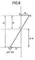
- FIG. 8shows the relationship of the projection distance d P , the distance d S to the display unit and the deviation D C .
- D C d Pd h (d S - d p )
- D Cd p ⁇ d h d S - d p
- the right side of EQ10signifies the proximal limit value of the image-fusible range with the screen center aligned with the point B. Specifically, the image-fusible range on this side of the point B is beyond the point C.
- k and ⁇ bare obtained by the convergence angle/base line distance detector 10.
- ⁇ wis a value known from lens data
- W S and d Sare values known from the display condition.
- the distance 1 to the subject 200 that satisfies the fusion conditionis expressed by the following equation. k ⁇ d h ⁇ tan ⁇ W + W S ⁇ tan ⁇ b W S - d h ⁇ tan ⁇ b - tan ⁇ W ⁇ l ⁇ ⁇ d P ⁇ W S ⁇ tan ⁇ b - d h ⁇ (d S - d P ) ⁇ tan ⁇ W ⁇ ⁇ ⁇ d P ⁇ W S + tan ⁇ b ⁇ d h ⁇ (d S - d P ) ⁇ tan ⁇ W ⁇ ⁇ ⁇ W ⁇ W S + tan ⁇ b ⁇ d h ⁇ (d S - d P ) ⁇ tan ⁇ W ⁇
- the image pick-up systemhas a function of determining whether the subject being captured meets the fusion condition, namely, falls within the image-pickable range (C ⁇ l ⁇ A), and informing the user of the determination result.
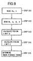
- FIG. 9is a flow diagram showing the control process that incorporates the user informing function.
- step S11the convergence angle ⁇ b and the base line distance 2k, set by the user, are read into the optical systems 101 and 102.
- step S12the known size W s of the image pick-up apparatus, the distance d s to the display units, the inter-pupillary distance d h , and the projection distance d P are also read.
- step S13the distal fusion limit point A is determined according to EQ6.
- step S14the proximal fusion limit point C is determined according to EQ10.
- step S15the image-pickable range is determined.
- the comparator 306compares the distance to the subject which the user looks at, calculated by the distance calculator 305, namely, the distance 1 to the subject which the user is now image-picking up, with the distal fusion limit point A and the proximal fusion limit point C. The comparator 306 then compares the distance to the object of the view point determined in step S11 with the image-pickable range determined in step S15. Specifically, the comparator 306 determines whether the object of the view point falls within or out of the image-pickable range. The comparison result is sent to the image controller 4. Either the display unit 201 or display unit 202 or both are provided with LEDs (not shown), and the display units 201 and 202 light or flash the LEDs to indicate whether the subject is within or out of the range.
- the LEDsmay be lit to indicate that the subject is out of the range and may be extinguished to indicate that the subject is within the range. Alternatively, the LEDs may be flashed to indicate that the subject is out of the range and may be extinguished to indicate that the subject is within the range.
- the image display 2may present the result of the above determination.
- the usereasily knows, when image-capturing, whether the main subject is within the image-fusible range according to the first embodiment, the userpicks up a stereoscopic image easy to see and imposing less fatigue.
- the observerlooks at the image of the subject displayed on the display units and the lines of sight of the observer are then detected.
- An unclaimed examplealso works to detect the lines of sight of the observer (user) who directly looks at the subject. This is because the distance 1 to the subject is also determined from the lines of sight of the user who directly looks at the subject.
- optical system 101 and CCD 103No particular optical specifications are set for the optical system 101 and CCD 103. Any systems are perfectly acceptable as long as the optical system 101 and CCD 103 in pairs are respectively identical, in optical specification, to the optical system 102 and CCD 104 in pairs.
- image pickingis performed in a cross method in which the camera optical axes cross each other.
- image pickingis performed in a parallel method in which the camera optical axes run in parallel.
- the line-of-sight detectionis not limited to the method in which the angle of rotation of the eyeball is detected.
- any other methodmay be used, including the EPG method for making use of a voltage difference between the voltages of the eyeballs, the method of using a difference in reflectance between the white and the pupil in the sclera of the eye, and the search coil method in which a coil-embedded contact lens is put on under the presence of a magnetic field to measure the movement of the eyeballs.
- the image display 2 in the embodimentis a fixed type.
- the embodimentalso works in any other appropriate display means such as a head-mounted display (HMD).
- HMDhead-mounted display
- the medium of the image memory 9 in the embodimentis a magnetic tape.
- the embodimentis not limited to this.
- the image memory 9may be an IC memory, a magneto-optical disc, a DVD disc, a compact disc, or a PD disc.
Landscapes
- Engineering & Computer Science (AREA)
- Multimedia (AREA)
- Signal Processing (AREA)
- Testing, Inspecting, Measuring Of Stereoscopic Televisions And Televisions (AREA)
Description
- The present invention relates to an image pick-upapparatus for stereoscope for picking up parallax imagesfor stereoscopic viewing. More particularly, the presentinvention relates to an image pick-up apparatus forpicking up, without user intervention, parallax imagesthat satisfy binocular fusion conditions and an imagepick-up apparatus that lets a user know whether thebinocular fusion conditions are satisfied.
- Some known stereoscopic image pick-up apparatusescapture parallax images from a plurality of view pointsusing a plurality of cameras. In such a stereoscopicimage pick-up apparatus, a plurality of cameras aremounted on tripod heads, and a user manually adjusts aspacing and a convergence angle between camera axes,based on his or her operational experience, depending ona scene to be captured, and image-captures the scenewhile actually observing the stereoscopic view on amonitor.
- Such an experience-based operation is notefficient, and no good result is expected when there isno one available who has a good knowledge of picking upstereoscopic images.
- Head-mounted displays and eyeglass-type displayshave been developed today, and these displays let animage for the right eye to be selectively presented onthe right eye and an image for the left eye to beselectively presented on the left eye. A stereoscopicimage producing a depth perception is thus observed. Aliquid-crystal display is combined with a lenticularsheet having a predetermined pitch or a mask withapertures and non-apertures formed in a predeterminedpattern to impart a directivity to a light ray from theliquid-crystal display, and by making the directivitymatch the pattern of the image presented on the liquid-crystaldisplay, the observer watches the image for theright eye on the right eye and the image for the lefteye on the left eye. The observer thus enjoys the imagepresenting depth.
- Conventionally, the image presented is typicallyacquired through a binocular-type camera having two lenssets. An apparatus, disclosed in Japanese ExaminedPatent Publication No. JP-A-8-27499 (telescopic televisionimage pick-up apparatus), does not require two lens sets.This apparatus includes two liquid-crystal shutters, a total reflection mirror and a half mirror and picks upalternately left and right parallax images through asingle lens set.
- Regardless of the above binocular system or thesystem picking up alternately left and right images in atime division manner, the adjustment of a parallaxbetween left and right images, namely, the adjustment ofconvergence is required during image-capturing. Theconvergence adjustment is typically manually performed.
- The above binocular-type camera employs two lenssets, one for forming the image for the right eye andthe other for forming the image for the left eye, andthe user feels fatigue when observing a stereoscopicimage or cannot to attain image fusion at all, ifperformance differences due to manufacturing error (forexample, in magnification, deviation in optical axis,tint, brightness, distortion, field tilt and the like)are present between the two lenses. To make the two lenssets match in performance, the accuracy of componentsneeds to be heightened. Adjustment is further requiredif the improved accuracy of components is still notsufficient enough. To compensate for performancedifference, special means is used, for example, imagesare electronically corrected. When a zoom lens is used,the zoom variator operations of the left and right lenssets must be interlocked in a state with these performances factored in. This arrangement is costly andtime consuming to manufacture, and is inadequate formass production.
- To observe the images picked up by the binocular-typecamera, two monitors are typically required. Theuse of the two monitors is not practical. To record thetwo images, a special recording device is needed tosynchronize the one image to the other. Without using it,the conversion of two image signals into one imagesignal is contemplated. To convert the two image signalsinto one image signal, however, a special converter isrequired to alternately display and record the left andright parallax images. Compared with a single lenscamera, the binocular-type camera itself is bulky. Theentire system of the image pick-up apparatus, in need ofthe above-described special devices, fails to achievewidespread commercial acceptance among users because ofits bulkier, costlier and less mobile design.
- The time-division camera proposed in the above-citedJapanese Examined Patent Publication No. JP-A-8-27499combines the optical paths for left and right parallaximages at a half mirror into one optical path to guideimages to a single lens. When images are transmittedthrough or reflected from the half mirror beforeentering the lens, the quantity of light is reduced tohalf or smaller. The arrangement disclosed in the above-cited Japanese Examined Patent Publication No. JP-A-8-27499theoretically presents a difference between the lengthsof the optical paths of the left and right parallaximages, suffering a magnification difference between theleft and right images. This becomes a cause of thefatigue of the user when he or she observes the imagespicked-up, and as a result, the user cannot observe theimages fused and cannot observe them in a stereoscopicview.
- Moreover, document EP-A-0 641 132 discloses a stereoscopicimage pick-up and display apparatus, wherein two camera bodieseach having an objective lens are operated and the outputsignals are further evaluated. A convergence control isperformed so that the optical axes of the cameras converge atan optimum point to ensure that the parallax of the capturedimages comes within the binocular fusing range of a viewer.Specifically, a parallax calculator is provided forcalculating the parallax of an image and the parallax of thenearest object is used for calculating the depth-wise positionof an object to be reproduced at the nearest point when acaptured image is displayed by the stereoscopic image displayapparatus. The fusing range is defined on the depth displayposition calculator, and the converging angle is controlled ina manner that the object at the nearest point is positionedwithin the fusional range of the viewer. Furthermore, a line-of-sightdetecting means is used for detecting the point onwhich the viewer's eye is focused.
- Furthermore, document JP-A-7 067 023 discloses a multi-eyeimage pick-up apparatus with immediate image pick-up wherein afirst and a second video camera portion are provided forpicking up a stereoscopic image. When both camera portions areoperated, the optical axis thereof is controlled and thecontrol means sets the optical axes of the first and thesecond video camera portions at predetermined optical axisangles. Furthermore, the apparatus comprises means for visualaxis detection, thereby determining the position of the eyeballand, upon data evaluation, the viewing direction of theuser.
- Accordingly, it is an object of the present invention toprovide an image pick-up apparatus through which the user orviewer easily learns during image-picking up whether a mainsubject falls within a range of image fusion.
- This object is accomplished according to the present inventionby an image pick-up apparatus and an image pick-up method asset out in the appended claims.
- The present invention provides an image pick-up apparatus forcapturing images for stereoscopic viewing, which comprises image pick-upmeans for picking up left and right parallax images of amain subject respectively for the left and right eyes,display means for displaying the left and right parallaximages, picked up by the image pick-up means, line-of-sightdetection means for detecting the lines of sightof the left and right eyes, looking the respective images displayed by the display means, and determiningmeans for determining, based on the output of the line-of-sightdetection means, whether the main subject fallswithin an image-fusible range. The apparatus detects thelines of sight of an observer who observes the displaymeans on which the left parallax image and rightparallax image are presented, and, instead of theobserver, determines, based on the lines of sight,whether the subject falls within the image-fusible range.
- In a preferred embodiment of the preset invention,the determination result provided by the determiningmeans is reported to the user.
- In a preferred embodiment of the presentinvention, an image-fusible range is defined by theinter-pupillary distance and the distance of distinctvision of a user.
- In a preferred embodiment of the presentinvention, the image date of the parallax images isstored in a memory in response to the output of thedetermining means.
- Since the detected lines of sight of the user arethe ones that look toward the display parallax images,the data about the lines of sight need to be convertedinto those in the coordinate systems of the image pick-upmeans. In a preferred embodiment of the presentinvention, the line-of-sight detection means further comprises converting means for converting the left andright lines of sight of a user into left and rightdirection vectors that are respectively expressed inleft and right coordinate systems of the image pick-upmeans, and coordinates calculator means for calculatingthe coordinate values of the crossing point of the leftand right direction vectors in the world coordinatesystem.
- In a preferred embodiment of the presentinvention, the image-fusible range is expressedaccording to a farthest position and a nearest positionfrom the view point of the user in the direction ofdepth. In a preferred embodiment, the farthest positionof the image-fusible range is set to be a point so thatthe horizontal distance between two second points on theleft and right image planes of the image pick-up meanscorresponding to a first point (A) of the farthestposition is substantially equal to the inter-pupillarydistance of the user. The nearest position of the image-fusiblerange is set to be a point so that a position(C') where two points on the left and right image planesof the image pick-up means corresponding to a firstpoint (C) of the nearest position, through perspectivetransformation based on the left and right view pointsof the user, look standing out to the user, isapproximately equal to the point at the distance ofdistinct vision of the user.
- FIG. 1 is a block diagram showing theconstruction of a first embodiment of the presentinvention;
- FIG. 2 is an explanatory diagram showing theposition of the eyes of an observer relative to anoptical system of an image pick-up apparatus of thefirst embodiment of the present invention;
- FIG. 3 is a flow diagram showing a controlprocess for measuring a distance to a subject based onthe line-of-sight data of the observer in the firstembodiment of the present invention;
- FIG. 4 is an explanatory diagram showing theoperation executed in step S8 through step S10 in thecontrol process shown in FIG. 3;
- FIG. 5 is an explanatory diagram illustrating theprinciple of determining an image-fusible range;
- FIG. 6 is an explanatory diagram illustrating theprinciple of determining the farthest position of the image-fusible range;
- FIG. 7 is an explanatory diagram illustrating theprinciple of determining the nearest position of theimage-fusible range;
- FIG. 8 is an explanatory diagram illustrating theprinciple of determining the nearest position of theimage- fusible range;
- FIG. 9 is a flow diagram showing the controlprocess for determining the image-fusible range.
- Referring to the drawings, the preferredembodiment of thepresent invention is now discussed.
- FIG. 1 is a block diagram showing theconstruction of a "stereoscopic image pick-up apparatus"according to a first embodiment of the present invention.
- Referring to FIG. 1, there is shown a stereocamera 1 for capturing a plurality of parallax images,and in the first embodiment, the stereo camera 1comprises a right optical system 101 for capturing aparallax image for the right eye and CCD 103 of aphotoelectric converter and a left optical system 102for capturing a parallax image for the left eye and CCD104 of a photoelectric converter.
- The pair of optical system 101 and CCD 103 isidentical in optical specification to the pair ofoptical system 102 and CCD 104. The optical system 101and CCD 103 and the optical system 102 and CCD 104 arearranged so that the spacing between the two pairs(hereinafter referred to as a base line distance) andthe angle made between the two pairs (hereinafter referred to as a convergence angle) are variably setwith an unshown mechanism. The base line distance andthe convergence angle are adjusted by a knownconvergence/base line distance adjuster 11.
- A convergence angle/base line distance detector10 detects the convergence angle and base line distancewith its unshown encoder.
- FIG. 2 shows the positions of the optical systems101 and 102 relative to a main subject. As shown, let brepresent the convergence angle between the opticalsystems 101 and 102, and 2k represent the base linedistance. As already described, the adjuster 11 adjuststhe convergence angle b and the base line distance 2k,and an adjusted angle is detected by the detector 10,and is then sent to a calculating unit 3 (FIG. 1) to bedescribed later.
- An image display 2 includes a right display unit201 for the right eye, a left display unit 202 for theleft eye, a right line-of-sight detector 203, and a leftline-of-sight detector 204.
- The right display unit 201 and left display unit202 are identical in specification, and are the so-calledretinal display that provides an image throughthe after image effect by irradiating and scanning theretina with a light beam from a liquid crystal, CRT, LEDor laser, each equipped with an observation optical system. In the first embodiment, the display units 201and 202 respectively scan the left and right retinas bya light beam from an LED circuit 12 to give left andright stereoscopic images to the user.
- A right line-of-sight detector 203 and left line-of-sightdetector 204. in image display 2 employ themethod of detecting the line of sight from the so-calledcorneal reflection light. To convert the line-of-sightinformation, determined using the corneal reflectionlight, into a coordinate system of an image, the imagedisplay 2 includes liquid-crystal displays LCD205 andLCD206. This method is disclosed in detail in JapaneseUnexamined Patent Publication No. JP-A-5-68188, and thediscussion of the method is omitted here. The line-of-sightinformation about the eyeball obtained by theline-of-sight detectors 203 and 204 is sent to thecalculating unit 3 to be described later, and serves asa basis for the calculation of the direction vector ofthe line of sight.
- The calculating unit 3 of the image pick-upapparatus calculates an image-pickable range of thestereo camera 1 that assures that the left and rightparallax images picked up by the stereo camera 1 causesan image fusion on the user (such a range is hereinafterreferred to as "image-fusible range").
- The calculating unit 3, substantially realized by computer software, is shown in a functional blockdiagram in FIG. 1, and comprises a right line-of-sightrange calculator 301, a left line-of-sight rangecalculator 302, a line-of-sight vector calculator 303, acrossing point calculator 307, a distance calculator 305,an image-pickable range calculator 304, and a comparator306.
- The two line-of-sight range calculators 301 and302 are respectively connected to the right line-of-sightdetector 203 and the left line-of-sight detector204, and calculate the line-of-sight ranges for the leftand right eyes of the user based on the outputs from thetwo detectors 203 and 204. The left and right line-of-sightranges calculated are input to the line-of-sightvector calculator 303, which calculates the directionvectors of the left and right lines of sight (dR anddLto be described later). The crossing point calculator307 determines the coordinates of the crossing point ofthe lines of sight, based on the detected directionvectorsdR anddL of the lines of sight. The distancecalculator 305 calculates a distance 1 from the viewpoint of the user to the subject, based on the detecteddirection vectors of the lines of sight.
- The image-pickable range calculator 304calculates the image-pickable range (namely, between thedistal limit A of the range and the proximal limit B of the range in the direction of depth). The comparator 306compares the distance 1 to the subject, calculated bythe distance calculator 305, to the limit values A and B,calculated by the image-pickable range calculator 304,to determine whether the subject meets an image fusioncondition. Specifically, if the distance to the subject,calculated by the distance calculator 305, meets thefollowing equation,
- An image controller 4 controls the units in theimage pick-up apparatus. Specifically, the imagecontroller 4 controls right and left camera processors 5and 6, for the right and left eyes, which converts imagesignals from CCDs 103 and 104 into a predetermined imageformat. These processors 5 and 6, under the control ofthe image controller 4, convert the left and rightparallax images picked up by the stereo camera 1 intothe predetermined format and store them in an imagememory 9.
- To present stereoscopic images to the user, theimages in the image memory 9 are read and converted intovideo signals by the image controller 4, and the videosignals are then sent to the display units 201 and 202via drivers 7 and 8, respectively. The image controller 4 exchanges data with the image memory 9. The imagecontroller 4 also sends to the LED circuit 12 a signalthat controls the lighting and extinction of an unshownLED installed in the image display 2.
- A series of operations of the system are nowdiscussed.
- FIG. 3 shows the operation starting at the line-of-sightdetectors 203 and 204 and ending with thecalculating unit 3, particularly, to the process fordetermining the direction vectors of the lines of sightbased on the data detected by the line-of-sightdetectors 203 and 204.
- To detect the image-fusible range in the firstembodiment, the subject is picked-up using the stereocamera, and the parallax images in stereoscopic view arepresented to the user using the display. Specifically,observing the left and right parallax images presentedon the display, the observer indirectly looks at thesubject. The image pick-up apparatus then detects thelines of sight of the observer's eyes.
- Step S1 corresponds to the line-of-sightdetectors 203 and 204 shown in FIG. 1, steps S2 and S3correspond to the line-of-sight range detectors 301 and 302 shown in FIG. 1, step S4 corresponds to the line-of-sightvector calculator 303, steps S5, S6, S8, S9 andS10 correspond to the crossing point calculator 307, andstep S7 corresponds to the distance calculator 305.
- In step S1, the lines of sight, namely, thedirections of rotation of the eyeballs are detected,based on the corneal reflection phenomenon. As describedabove, each of the line-of-sight detectors 203 and 204has its own LCD and CCD. LCD 205 and LCD 206 irradiatethe eyeballs of the observer by infrared light beamshaving a known pattern. The patterned beams arereflected by the corneas, and are then captured by CCD207 and CCD 208 as images. Since LCD 205 and LCD 206 arebeforehand respectively aligned with CCD 207 and CCD 208in their respective coordinate systems, the pixelpositions on CCD 207 and CCD 208 are considered tocorrespond to the respective spot positions on LCD 205and LCD 206. In step S2, the coordinate values of eachbeam spot in each LCD coordinate system are determined.The coordinate values of the beam spot in each LCDcoordinate system represent the angle of rotation of therespective eyeball.
- In step S3, the coordinate values of the beamspot in each LCD coordinate system obtained in step S2are converted into the coordinate values in thecoordinate systems of the stereo camera 1 (namely, the coordinate systems of CCD 103 and CCD 104). Step S4determines direction vectorsdR anddL of straight linesthat connect the coordinates of the left beat spot andright beam spot, expressed in the coordinate systems ofthe stereo camera 1, to reference points of the opticalsystems 101 and 102. The direction vectors are lines ofsight expressed in the world coordinate system. The lineof sight expressed in the world coordinate system ishereinafter referred to as "line-of-sight vector" orsimply "direction vector".
- The right direction vectordR and left directionvectordL are not necessarily present in the same plane.It is thus determined in step S5 whether the rightdirection vectordR and left direction vectordL arepresent the same plane. When it is determined that thetwo vectors are present in the same plane, thecontroller 4 goes to step S6 to calculate the crossingpoint (designated X) of the right direction vectordR andleft direction vectordL in the world coordinate system.
- When the two vectors are not present in the sameplane, the controller 4 goes to step S8, where plane Pin which the right direction vectordR and the referencepoint of the right optical system 101 lie is determinedas shown in FIG. 4. In step S9, an orthogonal projectionvectordL' of the left direction vectordL with respectto the plane P is determined. In step S10, the coordinates of the crossing point (designated X') of theright direction vectordR and the left direction vectordL' is calculated in the world coordinate system. StepS7 determines the distance 1 between the predeterminedreference point of the stereo camera 1 (the center pointbetween the reference point of the right optical system101 and the reference point of the left optical system102) and the crossing point determined in either step S6or step S10 (X or X').
- Discussed next is the calculation of the range 1of the distance to the subject satisfying the imagefusion condition, namely, the image-pickable range ofdistance to the subject.
- A range within which humans can fuse left andright parallax images presented on display screens as astereoscopic image (an image-fusible range) is differentdepending on the distal side (beyond the displayscreens) or on the proximal side (on this side of thedisplay screens). The image-fusible range depends on thecharacteristics of the human eyes. Considering that theinter-pupillary distance of the human is about 65 mmwide, and that the distance of distinct vision of thehuman is about 200 mm, this system determines a distallimit A based on the human inter-pupillary distance(about 65 mm) and a proximal limit C based on thedistance of distinct vision.
- Referring to FIG. 5, the image-fusible range isdiscussed.
- As shown, the y axis represents the direction ofdepth, and the z axis represents the vertical directionof the apparatus. The x axis is perpendicular to thedirection of depth. FIG. 5 is drawn at a constant in thez axis.
- Referring to FIG. 5, there are shown a referencepoint OL of the left optical system 102 (the lens centerwhen the optical system is considered as a single thinlens) and a reference point OR of the right opticalsystem 101 (the lens center when the optical system isconsidered as a single thin lens). When the opticalsystems 101 and 102 are set up, the reference points OLand OR are fixed points, and the crossing point B of theoptical axes of the optical systems 101 and 102 alsobecomes fixed.
- Let A represent a distal limit point of theimage-fusible range with respect to the point B and letC represent a proximal limit point of the image-fusiblerange with respect to the point B. The point B thencoincides with the center of the image screen of theleft and right optical systems 102 and 101. Since thepoint B has zero parallax, the point B appears as apoint on the display screen to the observer looking atthe stereoscopic image displayed. To the same observer, the point A appears as point present beyond the displayscreen and the point C appears as a point on this sideof the display screen.
- With the origin of the x-y coordinates positionedat the center of the base line distance between thepoints OL and OR, these points are A(0,A), B(0,B), C(0,C),OL(-k,0), and OR(k,0). Furthermore, b, a, and crepresent the following angles.
∠BOLO = ∠BORO = b
∠BOLA = ∠BORA = a
∠BOLC = ∠BORC = cSince the point B is the crossing point of the opticalaxes of the two optical systems 101 and 102 as alreadydescribed, it is possible to make an image pick-up planecoincide with a plane which is perpendicular to eachoptical axis and in which the point B lies. Referring toFIG. 6, a virtual image pick-up plane of the leftoptical system 102 is set up to be aligned on the pointB. The distal point A and the proximal point Crespectively become a point AL and a point CL on thevirtual image pick-up plane. - Let 2w represent the lens view angle of each ofthe optical systems 101 and 102. The display units 201 and 202 presenting the parallax images each have ahorizontal width of 2Ws, and are positioned in front ofthe observer with a predetermined distance ds allowedtherebetween. In this setup, the length of the virtualimage pick-up plane shown in FIG. 6 is preferably equalto the horizontal dimension of each of the display units201 and 202. With this arrangement, the size of thevirtual image pick-up plane is 2Ws. As shown in FIG. 6,the points A and C are present within an angle range of2w.
- Referring to FIG. 6, the left eye of the observersees the point A as the point AL' on the image pick-upplane, though the point A is actually present straightahead of the observer. The reason why there is adistance BA'L between the point B and the point A'L isthat the two eyes of human are spaced having a parallax.The distance BA'L is the quantity that may be called aparallax of the subject, and is expressed in a deviationon the image. Let DA represent the deviation of thepoint A and DB represent the deviation of the point C,and the following equation holds.
- In determining the fusion condition in the imagepick-up system, the left and right parallax images areobtained by picking up a subject 200 on the stereocamera 1 of FIG. 1 (with its base line distance 2k andconvergence angle b) and the parallax images aredisplayed on the display units 201 and 202 (with theirhorizontal dimensions of 2Ws) placed at a position infront of the observer with the predetermined distance dsallowed. A determination is made of whether the left andright parallax images are displayed in a fused state tothe eyes of the observer. Specifically, thedetermination is made depending on whether the distance1 from the stereo camera 1 to the subject satisfies theabove parameters (namely, the fusion condition, to bedescribed later, determined by the base line distance of2k, the convergence angle of b, the distance ds to thedisplay units and the size 2Ws of the display units).
- Let 2dh represent the inter-pupillary distance ofthe observer, and as can be seen from FIG. 6, when thedeviation of the point A, namely, the distance BA'L(=2DA) is smaller than 2dh, in other words, 2DA≦2dh, thesubject on this side of the point A must be fused. The following equation thus holds.
- The following equation is derived from EQ1, EQ3through EQ5.
- The right side of EQ 6 signifies the image-fusiblerange beyond the screen with the point B alignedwith the center of the screen. Specifically, if thesubject 200 is beyond the point B but on this side ofthe point A defined by the following equation, thesubject 200 is within the fusible range.
- Referring to FIG. 7, the point C is nowconsidered.
- FIG. 7 shows not only the virtual image pick-upplane 250L but also the virtual image pick-up plane 250R.Specifically, images AL and CL, corresponding to thepoints A and C, are obtained in the right image pick-upplane 250L, and images AR and CR, corresponding to thepoints A and C, are obtained in the left image pick-upplane 250R. If the observer looks at the image pick-upplane with both eyes, the left and right fields of vieware combined on a single virtual plane 400. On thevirtual plane 400, points A'L and A'R are formed for thepoint A, and points B'L and B'R are formed for the pointB. To the observer, the point A appears to be present ata crossing point A' where a straight line 300Lconnecting the left eye to the point A'L intersects astraight line 300R connecting the right eye to the pointA'R. And the point C appears to be present at a crossingpoint C' where a straight line 350L connecting the lefteye to the point C'L intersects a straight line 350Rconnecting the right eye to the point C'R. In otherwords, the point A appears to stand back by a distance dB,and the point C appears to be projected by a distance dPas shown in FIG. 7.
- FIG. 8 shows the relationship of the projectiondistance dP, the distance dS to the display unit and thedeviation DC. As can be seen from FIG. 8, the followingequation holds.
- The right side of EQ10 signifies the proximallimit value of the image-fusible range with the screencenter aligned with the point B. Specifically, theimage-fusible range on this side of the point B isbeyond the point C.
- k and b are obtained by the convergenceangle/base line distance detector 10. w is a valueknown from lens data, and WS and dS are values known fromthe display condition. In this embodiment, dh and dp arepredetermined values (dh=65 mm, dp=200 mm), though thepresent invention is not limited to these values.
- From the above discussion, the distance 1 to thesubject 200 that satisfies the fusion condition isexpressed by the following equation.
- The principle of the determination of whether thesubject meets the fusion condition in the image pick-upsystem has been discussed.
- The image pick-up system has a function ofdetermining whether the subject being captured meets thefusion condition, namely, falls within the image-pickablerange (C ≤ ℓ ≤ A), and informing the user ofthe determination result.
- FIG. 9 is a flow diagram showing the controlprocess that incorporates the user informing function.
- In step S11, the convergence angle b and the baseline distance 2k, set by the user, are read into theoptical systems 101 and 102. In step S12, the known sizeWs of the image pick-up apparatus, the distance ds to thedisplay units, the inter-pupillary distance dh, and theprojection distance dP are also read.
- In step S13, the distal fusion limit point A isdetermined according to EQ6. In step S14, the proximalfusion limit point C is determined according to EQ10. Instep S15, the image-pickable range is determined.
- The comparator 306 compares the distance to thesubject which the user looks at, calculated by thedistance calculator 305, namely, the distance 1 to thesubject which the user is now image-picking up, with thedistal fusion limit point A and the proximal fusionlimit point C. The comparator 306 then compares thedistance to the object of the view point determined instep S11 with the image-pickable range determined instep S15. Specifically, the comparator 306 determineswhether the object of the view point falls within or outof the image-pickable range. The comparison result issent to the image controller 4. Either the display unit201 or display unit 202 or both are provided with LEDs(not shown), and the display units 201 and 202 light orflash the LEDs to indicate whether the subject is withinor out of the range. The LEDs may be lit to indicate that the subject is out of the range and may beextinguished to indicate that the subject is within therange. Alternatively, the LEDs may be flashed toindicate that the subject is out of the range and may beextinguished to indicate that the subject is within therange. The image display 2 may present the result of theabove determination.
- As described above, when image-picking up, theuser easily knows whether the main subject is within theimage-fusible range (image-pickable range).
- Since the user easily knows, when image-capturing,whether the main subject is within the image-fusiblerange according to the first embodiment, the userpicksup a stereoscopic image easy to see and imposing lessfatigue.
- A diversity of modifications of theembodiment are contemplated.
- In the embodiment, the observer looks atthe image of the subject displayed on the display unitsand the lines of sight of the observer are then detected.An unclaimed example also works to detect the lines ofsight of the observer (user) who directly looks at the subject. This is because the distance 1 to the subjectis also determined from the lines of sight of the userwho directly looks at the subject.
- No particular optical specifications are set forthe optical system 101 and CCD 103. Any systems areperfectly acceptable as long as the optical system 101and CCD 103 in pairs are respectively identical, inoptical specification, to the optical system 102 and CCD104 in pairs.
- In the embodiment, image picking isperformed in a cross method in which the camera opticalaxes cross each other. According to an example,image picking is performed in a parallelmethod in which the camera optical axes run in parallel.
- The line-of-sight detectionis not limited to the method in which theangle of rotation of the eyeball is detected.Alternatively, any other method may be used, includingthe EPG method for making use of a voltage differencebetween the voltages of the eyeballs, the method ofusing a difference in reflectance between the white andthe pupil in the sclera of the eye, and the search coilmethod in which a coil-embedded contact lens is put onunder the presence of a magnetic field to measure themovement of the eyeballs.
- The image display 2 in the embodiment is a fixed type. The embodiment also works in anyother appropriate display means such as a head-mounteddisplay (HMD).
- The medium of the image memory 9 in theembodiment is a magnetic tape. The embodiment isnot limited to this. Alternatively, the image memory 9may be an IC memory, a magneto-optical disc, a DVD disc,a compact disc, or a PD disc.
Claims (24)
- An image pick-up apparatus for capturing images forstereoscopic viewing, comprising:image pick-up means (1) for picking up left and rightparallax images including a main subject respectively for the leftand right eyes;display means (2) for displaying the left and rightparallax images, picked up by said image pick-up means;line-of-sight detection means (203, 204) for detectingthe lines of sight of the left and right eyes lookingtoward the respective images displayed by said displaymeans (2) in the coordinate system of said display means;distance calculation means (303, 307, 305) forcalculating a crossing point of thelines of sight of the left and right eyes detected by saidline-of-sight detection means,determining the main subject on the basis of thecalculated crossing point of the lines of sightin the coordinate system of said image pick-up meansand calculating a distancefrom the image pick-up means to the determined mainsubject;image-pickable range calculation means (304) forcalculating an image-fusible range based on angles of therespective image pick-up means, a distance between.theimage pick-up means, a distance from the left and righteyes to said display means, human-pupillary distance limit,and a proximal limit based on distance of distinct visionof human eyes; anddetermining means (306) for determining whether thedistance from said image pick-up means to said main subjectcalculated by said distance calculation means falls within image-fusible range calculated by said image-pickable rangecalculation means.
- An image pick-up apparatus according to claim 1, furthercomprising informing means for informing a user of adetermination result provided by said determining means(306).
- An image pick-up apparatus according to claim 2, whereinsaid informing means displays said determination result.
- An image pick-up apparatus according to claim 1, whereinthe output of said image pick-up means (1) is stored in amemory in response to the output of said determining means.
- An image pick-up apparatus according to claim 1, whereinsaid line-of-sight detection means (203, 204) furthercomprises:converting means (303, 304) for converting the leftand right lines of sight of a user into left and rightdirection vectors that are respectively expressed in leftand right coordinate systems of said image pick-up means;andcoordinates calculator means (307) for calculating thecoordinate values of the crossing point of the left andright direction vectors in the world coordinate system.
- An image pick-up apparatus according to claim 1, whereinsaid image-pickable range calculation means (304) expressessaid image-fusible range according to a farthest positionand a nearest position from said image pick-up means in thedirection of depth.
- An image pick-up apparatus according to claim 6, whereinsaid image-pickable range calculation means (304) sets thefarthest position of said image-fusible range to be a pointso that the horizontal distance between two second pointson the left and right image planes of said image pick-upmeans (1) corresponding to a first point (A) of saidfarthest position is substantially equal to the inter-pupillarydistance of the user.
- An image pick-up apparatus according to claim 6,wherein said image-pickable range calculation means (304)sets the nearest position of said image-fusible range to bea point so that a position (C') where two points on theleft and right image planes of said image pick-up meanscorresponding to a first point (C) of the nearest position,through perspective transformation based on the left andright view points of the user, look standing out to the user, is approximately equal to the point at the distanceof distinct vision of the user.
- An image pick-up apparatus according to claim 1,wherein said image display means (2) and said line-of-sightdetection means (203, 204) are built into a head-mounteddisplay.
- An image pick-up apparatus according to claim 9,wherein said head-mounted display comprises a light-emittingdiode.
- An image pick-up method for capturing images forstereoscopic viewing, comprising:an image pick-up step of picking up left and rightparallax images including a main subject respectively for the leftand right eyes by an image pick-up means;a display step of displaying the picked left and rightparallax images by a display means;a line-of-sight detection step (S1) of detecting thelines of sight of the left and right eyes looking towardthe respective displayed images in the coordinate system of said display means;a distance calculation step of calculatinga crossing point of the lines of sight ofthe left and right eyes detected by said line-of-sightdetection step,determining the main subject on the basis of thecalculated crossing point of the lines of sight in thecoordinate system of said image pick-up meansand calculating a distance from the imagepick-up means to the determined main subject;an image-pickable range calculation step ofcalculating an image-fusible range based on angles of therespective image pick-up means, a distance between theimage pick-up means, a distance from the left and righteyes to said display means, human-pupillary distance limit,and a proximal limit based on distance of distinct visionof human eyes; anda determining step of determining whether thedistance from said image pick-up means to said main subjectcalculated by said distance calculation step falls withinimage-fusible range calculated by said image-pickable rangecalculation step.
- An image pick-up method according to claim 11, furthercomprising the step of informing a user of thedetermination result of said determining step.
- An image pick-up method according to claim 12, whereinsaid informing step displays said determination result.
- An image pick-up method according to claim 11, whereinsaid determining step defines said image-fusible rangeaccording to the inter-pupillary distance and the distanceof distinct vision of a user.
- An image pick-up method according to claim 11, furthercomprising the step of storing the output of said imagepick-up step in a memory in response to the output of saiddetermining step.
- An image pick-up method according to claim 11, whereinsaid step of detecting the lines of sight comprises thestep of converting the left and right lines of sight of auser into left and right direction vectors that arerespectively expressed in left and right coordinate systemsin said image pick-up step; and
the step of calculating the coordinate values of acrossing point of the left and right direction vectors inthe world coordinate system. - An image pick-up method according to claim 16, whereinsaid determining step determines whether the calculated coordinate values of the crossing point in the worldcoordinate system fall within said image-fusible range.
- An image pick-up method according to claim 11, whereinsaid image-pickable range calculating step expresses saidimage-fusible range according to a farthest position and anearest position from the image pick-up means in thedirection of depth.
- An image pick-up method according to claim 18, whereinsaid image-pickable range calculating step sets thefarthest position of said image-fusible range to be a pointso that the horizontal distance between two second pointsin left and right image planes of said image pick-up stepcorresponding to a first point (A) of said farthestposition is substantially equal to the inter-pupillarydistance of the user.
- An image pick-up method according to claim 18, whereinsaid image-pickable range calculating step sets the nearestposition of said image-fusible range to be a point so thata position (C') where two points on the left and rightimage planes of said image pick-up step corresponding to afirst point (C) of the nearest position, throughperspective transformation based on the left and right viewpoints of the user, look standing out to the user, isapproximately equal to the point at the distance ofdistinct vision of the user.
- An image pick-up apparatus according to claim 1,further comprising:recording means for recording, in accordance with theoutput of said determining means, the left parallax imagesignal and the right parallax image signal from said imagepick-up means (1).
- An image pick-up method according to claim 11, furthercomprising:the recording step of recording, in accordance withthe output of said determining step, the left parallaximage signal and the right parallax image signal obtainedthrough said image pick-up step.
- An image pick-up apparatus according to claim 1,wherein said image pick-up means (1) comprises adjustingmeans for adjusting either the base line distance betweensaid first and second optical systems or the convergenceangle between said first and second optical systems, or foradjusting both the base line distance and the convergenceangle.
- A computer readable recording medium for storing aprogram that is executed by a computer, wherein said mediumstores a program that executes the method according toclaim 11.
Applications Claiming Priority (4)
| Application Number | Priority Date | Filing Date | Title |
|---|---|---|---|
| JP33299597AJP3976860B2 (en) | 1997-12-03 | 1997-12-03 | Stereoscopic imaging device |
| JP33299597 | 1997-12-03 | ||
| JP32369198 | 1998-11-13 | ||
| JP10323691AJP2000152282A (en) | 1998-11-13 | 1998-11-13 | 3D video camera |
Publications (3)
| Publication Number | Publication Date |
|---|---|
| EP0921694A2 EP0921694A2 (en) | 1999-06-09 |
| EP0921694A3 EP0921694A3 (en) | 2001-03-28 |
| EP0921694B1true EP0921694B1 (en) | 2005-06-08 |
Family
ID=26571274
Family Applications (1)
| Application Number | Title | Priority Date | Filing Date |
|---|---|---|---|
| EP98122894AExpired - LifetimeEP0921694B1 (en) | 1997-12-03 | 1998-12-02 | Stereoscopic image pick-up apparatus |
Country Status (3)
| Country | Link |
|---|---|
| US (2) | US6762794B1 (en) |
| EP (1) | EP0921694B1 (en) |
| DE (1) | DE69830459T2 (en) |
Families Citing this family (100)
| Publication number | Priority date | Publication date | Assignee | Title |
|---|---|---|---|---|
| US6483484B1 (en)* | 1998-12-18 | 2002-11-19 | Semiconductor Energy Laboratory Co., Ltd. | Goggle type display system |
| KR100354840B1 (en)* | 2000-05-09 | 2002-10-05 | 최부진 | Movie camera and photographing method for obtaing three-dimensional image |
| JP2002027496A (en)* | 2000-07-03 | 2002-01-25 | Canon Inc | Imaging lens unit, imaging device, and imaging system |
| JP2002095015A (en)* | 2000-09-11 | 2002-03-29 | Canon Inc | Imaging system, lens unit, imaging device |
| DE10063380B4 (en)* | 2000-12-19 | 2005-06-09 | Heraeus Med Gmbh | Method and device for video recording of an illuminated field |
| US6953249B1 (en) | 2001-01-29 | 2005-10-11 | Maguire Jr Francis J | Method and devices for displaying images for viewing with varying accommodation |
| US8085293B2 (en)* | 2001-03-14 | 2011-12-27 | Koninklijke Philips Electronics N.V. | Self adjusting stereo camera system |
| JP2003016435A (en)* | 2001-06-27 | 2003-01-17 | Matsushita Electric Ind Co Ltd | Individual authentication device and method |
| US7715595B2 (en)* | 2002-01-16 | 2010-05-11 | Iritech, Inc. | System and method for iris identification using stereoscopic face recognition |
| WO2003083781A1 (en)* | 2002-03-29 | 2003-10-09 | Koninklijke Philips Electronics N.V. | Method, system and computer program for stereoscopic viewing of 3d medical images |
| JP3788394B2 (en)* | 2002-06-13 | 2006-06-21 | ソニー株式会社 | Imaging apparatus and imaging method, and display apparatus and display method |
| US7102615B2 (en) | 2002-07-27 | 2006-09-05 | Sony Computer Entertainment Inc. | Man-machine interface using a deformable device |
| US8797260B2 (en) | 2002-07-27 | 2014-08-05 | Sony Computer Entertainment Inc. | Inertially trackable hand-held controller |
| US7883415B2 (en) | 2003-09-15 | 2011-02-08 | Sony Computer Entertainment Inc. | Method and apparatus for adjusting a view of a scene being displayed according to tracked head motion |
| US9474968B2 (en) | 2002-07-27 | 2016-10-25 | Sony Interactive Entertainment America Llc | Method and system for applying gearing effects to visual tracking |
| US8570378B2 (en) | 2002-07-27 | 2013-10-29 | Sony Computer Entertainment Inc. | Method and apparatus for tracking three-dimensional movements of an object using a depth sensing camera |
| US8313380B2 (en) | 2002-07-27 | 2012-11-20 | Sony Computer Entertainment America Llc | Scheme for translating movements of a hand-held controller into inputs for a system |
| US9393487B2 (en) | 2002-07-27 | 2016-07-19 | Sony Interactive Entertainment Inc. | Method for mapping movements of a hand-held controller to game commands |
| US7391409B2 (en)* | 2002-07-27 | 2008-06-24 | Sony Computer Entertainment America Inc. | Method and system for applying gearing effects to multi-channel mixed input |
| US7760248B2 (en) | 2002-07-27 | 2010-07-20 | Sony Computer Entertainment Inc. | Selective sound source listening in conjunction with computer interactive processing |
| US8686939B2 (en) | 2002-07-27 | 2014-04-01 | Sony Computer Entertainment Inc. | System, method, and apparatus for three-dimensional input control |
| US9682319B2 (en) | 2002-07-31 | 2017-06-20 | Sony Interactive Entertainment Inc. | Combiner method for altering game gearing |
| US20040041906A1 (en)* | 2002-09-04 | 2004-03-04 | Fruit Theodoric Benjamin | Method for producing a real-time, moving, stereoscopic, preview image |
| JP3926244B2 (en)* | 2002-09-26 | 2007-06-06 | 株式会社島津製作所 | Imaging device |
| JP2004179892A (en)* | 2002-11-26 | 2004-06-24 | Sanyo Electric Co Ltd | Imaging unit |
| US8072470B2 (en) | 2003-05-29 | 2011-12-06 | Sony Computer Entertainment Inc. | System and method for providing a real-time three-dimensional interactive environment |
| US7874917B2 (en) | 2003-09-15 | 2011-01-25 | Sony Computer Entertainment Inc. | Methods and systems for enabling depth and direction detection when interfacing with a computer program |
| US8287373B2 (en) | 2008-12-05 | 2012-10-16 | Sony Computer Entertainment Inc. | Control device for communicating visual information |
| US8323106B2 (en) | 2008-05-30 | 2012-12-04 | Sony Computer Entertainment America Llc | Determination of controller three-dimensional location using image analysis and ultrasonic communication |
| US10279254B2 (en) | 2005-10-26 | 2019-05-07 | Sony Interactive Entertainment Inc. | Controller having visually trackable object for interfacing with a gaming system |
| US9573056B2 (en) | 2005-10-26 | 2017-02-21 | Sony Interactive Entertainment Inc. | Expandable control device via hardware attachment |
| JP2006005608A (en)* | 2004-06-17 | 2006-01-05 | Hitachi Ltd | Imaging device |
| US8547401B2 (en)* | 2004-08-19 | 2013-10-01 | Sony Computer Entertainment Inc. | Portable augmented reality device and method |
| KR100800859B1 (en)* | 2004-08-27 | 2008-02-04 | 삼성전자주식회사 | Apparatus and method for inputting keys in HMD information terminal |
| US9033870B2 (en)* | 2004-09-24 | 2015-05-19 | Vivid Medical, Inc. | Pluggable vision module and portable display for endoscopy |
| US8878924B2 (en)* | 2004-09-24 | 2014-11-04 | Vivid Medical, Inc. | Disposable microscope and portable display |
| US8858425B2 (en)* | 2004-09-24 | 2014-10-14 | Vivid Medical, Inc. | Disposable endoscope and portable display |
| US8827899B2 (en)* | 2004-09-24 | 2014-09-09 | Vivid Medical, Inc. | Disposable endoscopic access device and portable display |
| US8982181B2 (en)* | 2006-06-13 | 2015-03-17 | Newbery Revocable Trust Indenture | Digital stereo photographic system |
| US20080013184A1 (en)* | 2006-07-14 | 2008-01-17 | Motorola, Inc. | Head's up display ambiguity eliminator |
| US8781151B2 (en) | 2006-09-28 | 2014-07-15 | Sony Computer Entertainment Inc. | Object detection using video input combined with tilt angle information |
| US8310656B2 (en) | 2006-09-28 | 2012-11-13 | Sony Computer Entertainment America Llc | Mapping movements of a hand-held controller to the two-dimensional image plane of a display screen |
| USRE48417E1 (en) | 2006-09-28 | 2021-02-02 | Sony Interactive Entertainment Inc. | Object direction using video input combined with tilt angle information |
| US11275242B1 (en) | 2006-12-28 | 2022-03-15 | Tipping Point Medical Images, Llc | Method and apparatus for performing stereoscopic rotation of a volume on a head display unit |
| US11228753B1 (en) | 2006-12-28 | 2022-01-18 | Robert Edwin Douglas | Method and apparatus for performing stereoscopic zooming on a head display unit |
| US10795457B2 (en) | 2006-12-28 | 2020-10-06 | D3D Technologies, Inc. | Interactive 3D cursor |
| US11315307B1 (en) | 2006-12-28 | 2022-04-26 | Tipping Point Medical Images, Llc | Method and apparatus for performing rotating viewpoints using a head display unit |
| JP5507797B2 (en)* | 2007-03-12 | 2014-05-28 | キヤノン株式会社 | Head-mounted imaging display device and image generation device |
| JP4714176B2 (en)* | 2007-03-29 | 2011-06-29 | 富士フイルム株式会社 | Stereoscopic apparatus and optical axis adjustment method |
| JP2009055554A (en)* | 2007-08-29 | 2009-03-12 | Fujifilm Corp | Flexible imaging device equipped with multiple imaging elements |
| US8542907B2 (en) | 2007-12-17 | 2013-09-24 | Sony Computer Entertainment America Llc | Dynamic three-dimensional object mapping for user-defined control device |
| US7802883B2 (en) | 2007-12-20 | 2010-09-28 | Johnson & Johnson Vision Care, Inc. | Cosmetic contact lenses having a sparkle effect |
| US8115825B2 (en) | 2008-02-20 | 2012-02-14 | Apple Inc. | Electronic device with two image sensors |
| CN102016877B (en) | 2008-02-27 | 2014-12-10 | 索尼计算机娱乐美国有限责任公司 | Method for capturing depth data of a scene and applying computer actions |
| JP5079549B2 (en)* | 2008-03-03 | 2012-11-21 | パナソニック株式会社 | Imaging device and imaging device body |
| US8368753B2 (en) | 2008-03-17 | 2013-02-05 | Sony Computer Entertainment America Llc | Controller with an integrated depth camera |
| US8961313B2 (en) | 2009-05-29 | 2015-02-24 | Sony Computer Entertainment America Llc | Multi-positional three-dimensional controller |
| JP5210843B2 (en)* | 2008-12-12 | 2013-06-12 | パナソニック株式会社 | Imaging device |
| CN101588513B (en)* | 2009-01-07 | 2011-05-18 | 深圳市掌网立体时代视讯技术有限公司 | Device and method of stereo camera |
| GB2480193B (en)* | 2009-01-19 | 2015-01-21 | Minoru Inaba | Stereoscopic video imaging display system |
| US8527657B2 (en) | 2009-03-20 | 2013-09-03 | Sony Computer Entertainment America Llc | Methods and systems for dynamically adjusting update rates in multi-player network gaming |
| US8342963B2 (en) | 2009-04-10 | 2013-01-01 | Sony Computer Entertainment America Inc. | Methods and systems for enabling control of artificial intelligence game characters |
| US8393964B2 (en) | 2009-05-08 | 2013-03-12 | Sony Computer Entertainment America Llc | Base station for position location |
| US8142288B2 (en) | 2009-05-08 | 2012-03-27 | Sony Computer Entertainment America Llc | Base station movement detection and compensation |
| JP5409107B2 (en)* | 2009-05-13 | 2014-02-05 | 任天堂株式会社 | Display control program, information processing apparatus, display control method, and information processing system |
| JP5356952B2 (en)* | 2009-08-31 | 2013-12-04 | レムセン イノベーション、リミティッド ライアビリティー カンパニー | Display device |
| CN102033414B (en)* | 2009-09-27 | 2012-06-20 | 深圳市掌网立体时代视讯技术有限公司 | Stereoscopic digital imaging converging device and method |
| US8291322B2 (en)* | 2009-09-30 | 2012-10-16 | United Video Properties, Inc. | Systems and methods for navigating a three-dimensional media guidance application |
| JP5405264B2 (en) | 2009-10-20 | 2014-02-05 | 任天堂株式会社 | Display control program, library program, information processing system, and display control method |
| JP4754031B2 (en)* | 2009-11-04 | 2011-08-24 | 任天堂株式会社 | Display control program, information processing system, and program used for stereoscopic display control |
| US8780185B2 (en)* | 2009-11-25 | 2014-07-15 | Olympus Imaging Corp. | Image pickup apparatus having a display controlled using interchangeable lens information and/or finder information |
| US20110137727A1 (en)* | 2009-12-07 | 2011-06-09 | Rovi Technologies Corporation | Systems and methods for determining proximity of media objects in a 3d media environment |
| JP2011139296A (en)* | 2009-12-28 | 2011-07-14 | Sony Corp | Video signal processing apparatus and video signal processing method |
| EP2355526A3 (en) | 2010-01-14 | 2012-10-31 | Nintendo Co., Ltd. | Computer-readable storage medium having stored therein display control program, display control apparatus, display control system, and display control method |
| JP5446949B2 (en)* | 2010-02-03 | 2014-03-19 | ソニー株式会社 | Image processing apparatus, image processing method, and program |
| US9128367B2 (en)* | 2010-03-05 | 2015-09-08 | Panasonic Intellectual Property Management Co., Ltd. | 3D imaging device and 3D imaging method |
| JP5444452B2 (en) | 2010-03-05 | 2014-03-19 | パナソニック株式会社 | Stereo imaging device and stereo imaging method |
| JP5432365B2 (en) | 2010-03-05 | 2014-03-05 | パナソニック株式会社 | Stereo imaging device and stereo imaging method |
| WO2011148556A1 (en)* | 2010-05-25 | 2011-12-01 | パナソニック株式会社 | Image encoding apparatus, image encoding method, program and integrated circuit |
| US9693039B2 (en) | 2010-05-27 | 2017-06-27 | Nintendo Co., Ltd. | Hand-held electronic device |
| JP5425305B2 (en)* | 2010-05-31 | 2014-02-26 | 富士フイルム株式会社 | Stereoscopic image control apparatus, operation control method thereof, and operation control program thereof |
| EP2395765B1 (en) | 2010-06-14 | 2016-08-24 | Nintendo Co., Ltd. | Storage medium having stored therein stereoscopic image display program, stereoscopic image display device, stereoscopic image display system, and stereoscopic image display method |
| WO2012023168A1 (en)* | 2010-08-19 | 2012-02-23 | パナソニック株式会社 | Stereoscopic image capturing device, and stereoscopic image capturing method |
| KR101700363B1 (en)* | 2010-09-08 | 2017-01-26 | 삼성전자주식회사 | Digital photographing apparatus and method for controlling the same |
| KR101814798B1 (en)* | 2011-01-26 | 2018-01-04 | 삼성전자주식회사 | Apparatus for processing three dimension image and method for the same |
| US8718973B2 (en)* | 2011-09-09 | 2014-05-06 | Kabushiki Kaisha Toshiba | Method, device, and system for calculating a geometric system model using an area-simulating-volume algorithm in three dimensional reconstruction |
| JP6113411B2 (en)* | 2011-09-13 | 2017-04-12 | シャープ株式会社 | Image processing device |
| US20130083170A1 (en)* | 2011-10-03 | 2013-04-04 | Canon Kabushiki Kaisha | Stereoscopic image pickup apparatus |
| CN103809737A (en)* | 2012-11-13 | 2014-05-21 | 华为技术有限公司 | Method and device for human-computer interaction |
| TW201428675A (en) | 2013-01-08 | 2014-07-16 | Pixart Imaging Inc | Video generating system and related method thereof |
| JP6209740B2 (en)* | 2013-03-15 | 2017-10-11 | パナソニックIpマネジメント株式会社 | Camera controller device |
| US9161020B2 (en)* | 2013-04-26 | 2015-10-13 | B12-Vision Co., Ltd. | 3D video shooting control system, 3D video shooting control method and program |
| US9503705B2 (en)* | 2013-12-12 | 2016-11-22 | Lenovo (Singapore) Pte. Ltd. | Stereoscopic image generation |
| CN105025193B (en) | 2014-04-29 | 2020-02-07 | 钰立微电子股份有限公司 | Portable stereo scanner and method for generating stereo scanning result of corresponding object |
| US9507241B1 (en) | 2015-11-17 | 2016-11-29 | Lenovo (Singapore) Pte, Ltd. | Adjustable camera field of view |
| WO2018076202A1 (en)* | 2016-10-26 | 2018-05-03 | 中国科学院深圳先进技术研究院 | Head-mounted display device that can perform eye tracking, and eye tracking method |
| EP3415078A1 (en)* | 2017-06-16 | 2018-12-19 | Essilor International | Method and system for determining a pupillary distance of an individual |
| CN113395410B (en)* | 2017-12-15 | 2023-04-18 | 浙江舜宇智能光学技术有限公司 | Video synchronization method applied to multi-view camera |
| CN109710477B (en)* | 2018-12-28 | 2019-10-18 | 哈尔滨拓博科技有限公司 | The system and method that a kind of pair of plane interaction carries out automatic test |
| US12287917B2 (en)* | 2022-12-26 | 2025-04-29 | Canon Kabushiki Kaisha | Line-of-sight detection device and head mounted display device |
Family Cites Families (28)
| Publication number | Priority date | Publication date | Assignee | Title |
|---|---|---|---|---|
| US3251933A (en)* | 1962-10-31 | 1966-05-17 | Vare Ind Inc | Three-dimensional television system |
| US4437745A (en)* | 1982-09-30 | 1984-03-20 | Stephen Hajnal | Three dimensional camera system |
| GB8430980D0 (en) | 1984-12-07 | 1985-01-16 | Robinson M | Generation of apparently three-dimensional images |
| DE3640731A1 (en) | 1986-11-28 | 1988-06-09 | Standard Elektrik Lorenz Ag | ARRANGEMENT FOR TRANSMITTING STEREOSCOPIC VIDEO IMAGES |
| JPH0827499B2 (en) | 1987-12-03 | 1996-03-21 | 松下電器産業株式会社 | Imaging device for stereoscopic television |
| US5003385A (en)* | 1988-08-24 | 1991-03-26 | Kabushiki Kaisha Toshiba | Stereoscopic television system |
| DE69210303T2 (en)* | 1991-05-23 | 1996-11-14 | Hitachi Ltd | Widescreen television receiver with aspect ratio conversion function and method for displaying an enlarged portion |
| JPH0568188A (en) | 1991-09-06 | 1993-03-19 | Canon Inc | Video camera |
| JPH05292543A (en)* | 1992-04-15 | 1993-11-05 | Komatsu Ltd | Visual device |
| JP2888713B2 (en)* | 1993-01-14 | 1999-05-10 | キヤノン株式会社 | Compound eye imaging device |
| US5625408A (en)* | 1993-06-24 | 1997-04-29 | Canon Kabushiki Kaisha | Three-dimensional image recording/reconstructing method and apparatus therefor |
| JPH0767023A (en) | 1993-08-26 | 1995-03-10 | Canon Inc | Compound eye imaging device |
| DE69417824T4 (en)* | 1993-08-26 | 2000-06-29 | Matsushita Electric Industrial Co., Ltd. | Stereoscopic scanner |
| US5864360A (en)* | 1993-08-26 | 1999-01-26 | Canon Kabushiki Kaisha | Multi-eye image pick-up apparatus with immediate image pick-up |
| JP3054002B2 (en)* | 1993-09-01 | 2000-06-19 | キヤノン株式会社 | Compound eye imaging device |
| JPH0847000A (en)* | 1994-08-02 | 1996-02-16 | Canon Inc | Compound-eye image pickup device, image signal conversion device, display device, and compound-eye image pickup image recording / reproducing device |
| JP3478606B2 (en)* | 1994-10-12 | 2003-12-15 | キヤノン株式会社 | Stereoscopic image display method and apparatus |
| US6606113B2 (en)* | 1995-05-24 | 2003-08-12 | Olympus Optical Co., Ltd. | Stereoscopic endocsope system and TV imaging system for endoscope |
| US5864359A (en)* | 1995-05-30 | 1999-01-26 | Smith & Nephew, Inc. | Stereoscopic autofocusing based on comparing the left and right eye images |
| US5828913A (en) | 1995-06-06 | 1998-10-27 | Zanen; Pieter O. | Method for three dimensional measurement and imaging having focus-related convergence compensation |
| US5532777A (en)* | 1995-06-06 | 1996-07-02 | Zanen; Pieter O. | Single lens apparatus for three-dimensional imaging having focus-related convergence compensation |
| US6683652B1 (en)* | 1995-08-29 | 2004-01-27 | Canon Kabushiki Kaisha | Interchangeable lens video camera system having improved focusing |
| US6088006A (en)* | 1995-12-20 | 2000-07-11 | Olympus Optical Co., Ltd. | Stereoscopic image generating system for substantially matching visual range with vergence distance |
| JP3771964B2 (en)* | 1996-03-12 | 2006-05-10 | オリンパス株式会社 | 3D image display device |
| JPH1070742A (en)* | 1996-08-29 | 1998-03-10 | Olympus Optical Co Ltd | Twin-lens video display device |
| JP2000354257A (en)* | 1999-06-10 | 2000-12-19 | Sony Corp | Image processor, image processing method and program provision medium |
| US6864910B1 (en)* | 1999-06-30 | 2005-03-08 | Canon Kabushiki Kaisha | Optical apparatus |
| JP2001218228A (en)* | 2000-02-01 | 2001-08-10 | Canon Inc | Optical system for stereoscopic image photographing and stereoscopic image photographing apparatus using the same |
- 1998
- 1998-12-01USUS09/203,997patent/US6762794B1/ennot_activeExpired - Fee Related
- 1998-12-02EPEP98122894Apatent/EP0921694B1/ennot_activeExpired - Lifetime
- 1998-12-02DEDE69830459Tpatent/DE69830459T2/ennot_activeExpired - Lifetime
- 2004
- 2004-01-22USUS10/763,756patent/US20040150728A1/ennot_activeAbandoned
Also Published As
| Publication number | Publication date |
|---|---|
| US20040150728A1 (en) | 2004-08-05 |
| US6762794B1 (en) | 2004-07-13 |
| DE69830459D1 (en) | 2005-07-14 |
| EP0921694A2 (en) | 1999-06-09 |
| EP0921694A3 (en) | 2001-03-28 |
| DE69830459T2 (en) | 2006-03-23 |
Similar Documents
| Publication | Publication Date | Title |
|---|---|---|
| EP0921694B1 (en) | Stereoscopic image pick-up apparatus | |
| EP0641132B1 (en) | Stereoscopic image pickup apparatus | |
| JP3186448B2 (en) | 3D TV camera | |
| US6864910B1 (en) | Optical apparatus | |
| EP0837603B1 (en) | System for controlling the focus of variable-focus lenses by detection of the spatial relationship of the eyes of a person | |
| JP3984907B2 (en) | Image observation system | |
| EP0744036B1 (en) | Image display apparatus | |
| CN108351515A (en) | Eye projection system and method | |
| US6788274B2 (en) | Apparatus and method for displaying stereoscopic images | |
| KR20120105495A (en) | Stereoscopic imaging device | |
| JPH07167633A (en) | Stereoscopic image pickup and display device | |
| JPH08194274A (en) | Stereoscopic image pickup device | |
| JP2002223458A (en) | 3D image creation device | |
| KR101526557B1 (en) | Apparatus and method for gaze tracking based on multiple camera | |
| JP5474530B2 (en) | Stereoscopic image display device | |
| JP2986659B2 (en) | Stereoscopic image imaging and display system | |
| JP3976860B2 (en) | Stereoscopic imaging device | |
| JP4208351B2 (en) | Imaging apparatus, convergence distance determination method, and storage medium | |
| JPH08205200A (en) | Three-dimensional image pickup device | |
| JP3520197B2 (en) | 3D camera device | |
| JP2024178584A (en) | IMAGE OBSERVATION APPARATUS, CONTROL METHOD FOR IMAGE OBSERVATION APPARATUS, AND PROGRAM | |
| JPH08191462A (en) | Stereoscopic video reproducing device and stereoscopic image pickup device | |
| JPH02291787A (en) | Wide visual field display device and wide visual field photography device | |
| JP2001016619A (en) | Imaging device, method of determining convergence distance thereof, storage medium, and optical device | |
| JP4235291B2 (en) | 3D image system |
Legal Events
| Date | Code | Title | Description |
|---|---|---|---|
| PUAI | Public reference made under article 153(3) epc to a published international application that has entered the european phase | Free format text:ORIGINAL CODE: 0009012 | |
| AK | Designated contracting states | Kind code of ref document:A2 Designated state(s):DE FR GB IT NL | |
| AX | Request for extension of the european patent | Free format text:AL;LT;LV;MK;RO;SI | |
| PUAL | Search report despatched | Free format text:ORIGINAL CODE: 0009013 | |
| AK | Designated contracting states | Kind code of ref document:A3 Designated state(s):AT BE CH CY DE DK ES FI FR GB GR IE IT LI LU MC NL PT SE | |
| AX | Request for extension of the european patent | Free format text:AL;LT;LV;MK;RO;SI | |
| RIC1 | Information provided on ipc code assigned before grant | Free format text:7H 04N 13/02 A, 7H 04N 13/00 B | |
| 17P | Request for examination filed | Effective date:20010809 | |
| 17Q | First examination report despatched | Effective date:20010917 | |
| AKX | Designation fees paid | Free format text:DE FR GB IT NL | |
| GRAP | Despatch of communication of intention to grant a patent | Free format text:ORIGINAL CODE: EPIDOSNIGR1 | |
| RIN1 | Information on inventor provided before grant (corrected) | Inventor name:OGINO, SHIGERUC/O CANON KABUSHIKI KAISHA | |
| GRAS | Grant fee paid | Free format text:ORIGINAL CODE: EPIDOSNIGR3 | |
| GRAA | (expected) grant | Free format text:ORIGINAL CODE: 0009210 | |
| AK | Designated contracting states | Kind code of ref document:B1 Designated state(s):DE FR GB IT NL | |
| PG25 | Lapsed in a contracting state [announced via postgrant information from national office to epo] | Ref country code:NL Free format text:LAPSE BECAUSE OF FAILURE TO SUBMIT A TRANSLATION OF THE DESCRIPTION OR TO PAY THE FEE WITHIN THE PRESCRIBED TIME-LIMIT Effective date:20050608 Ref country code:IT Free format text:LAPSE BECAUSE OF FAILURE TO SUBMIT A TRANSLATION OF THE DESCRIPTION OR TO PAY THE FEE WITHIN THE PRE;WARNING: LAPSES OF ITALIAN PATENTS WITH EFFECTIVE DATE BEFORE 2007 MAY HAVE OCCURRED AT ANY TIME BEFORE 2007. THE CORRECT EFFECTIVE DATE MAY BE DIFFERENT FROM THE ONE RECORDED.SCRIBED TIME-LIMIT Effective date:20050608 | |
| REG | Reference to a national code | Ref country code:GB Ref legal event code:FG4D | |
| REF | Corresponds to: | Ref document number:69830459 Country of ref document:DE Date of ref document:20050714 Kind code of ref document:P | |
| NLV1 | Nl: lapsed or annulled due to failure to fulfill the requirements of art. 29p and 29m of the patents act | ||
| PLBE | No opposition filed within time limit | Free format text:ORIGINAL CODE: 0009261 | |
| STAA | Information on the status of an ep patent application or granted ep patent | Free format text:STATUS: NO OPPOSITION FILED WITHIN TIME LIMIT | |
| 26N | No opposition filed | Effective date:20060309 | |
| EN | Fr: translation not filed | ||
| PG25 | Lapsed in a contracting state [announced via postgrant information from national office to epo] | Ref country code:FR Free format text:LAPSE BECAUSE OF FAILURE TO SUBMIT A TRANSLATION OF THE DESCRIPTION OR TO PAY THE FEE WITHIN THE PRESCRIBED TIME-LIMIT Effective date:20060804 | |
| PG25 | Lapsed in a contracting state [announced via postgrant information from national office to epo] | Ref country code:FR Free format text:LAPSE BECAUSE OF FAILURE TO SUBMIT A TRANSLATION OF THE DESCRIPTION OR TO PAY THE FEE WITHIN THE PRESCRIBED TIME-LIMIT Effective date:20050608 | |
| PGFP | Annual fee paid to national office [announced via postgrant information from national office to epo] | Ref country code:DE Payment date:20141231 Year of fee payment:17 Ref country code:GB Payment date:20141222 Year of fee payment:17 | |
| REG | Reference to a national code | Ref country code:DE Ref legal event code:R119 Ref document number:69830459 Country of ref document:DE | |
| GBPC | Gb: european patent ceased through non-payment of renewal fee | Effective date:20151202 | |
| PG25 | Lapsed in a contracting state [announced via postgrant information from national office to epo] | Ref country code:DE Free format text:LAPSE BECAUSE OF NON-PAYMENT OF DUE FEES Effective date:20160701 Ref country code:GB Free format text:LAPSE BECAUSE OF NON-PAYMENT OF DUE FEES Effective date:20151202 |