EP0921490B1 - Electrical connector device for co-operating with a removable electronic medium - Google Patents
Electrical connector device for co-operating with a removable electronic mediumDownload PDFInfo
- Publication number
- EP0921490B1 EP0921490B1EP98122985AEP98122985AEP0921490B1EP 0921490 B1EP0921490 B1EP 0921490B1EP 98122985 AEP98122985 AEP 98122985AEP 98122985 AEP98122985 AEP 98122985AEP 0921490 B1EP0921490 B1EP 0921490B1
- Authority
- EP
- European Patent Office
- Prior art keywords
- electrical connector
- board
- connector device
- electrical
- face
- Prior art date
- Legal status (The legal status is an assumption and is not a legal conclusion. Google has not performed a legal analysis and makes no representation as to the accuracy of the status listed.)
- Expired - Lifetime
Links
Images


Classifications
- G—PHYSICS
- G06—COMPUTING OR CALCULATING; COUNTING
- G06K—GRAPHICAL DATA READING; PRESENTATION OF DATA; RECORD CARRIERS; HANDLING RECORD CARRIERS
- G06K7/00—Methods or arrangements for sensing record carriers, e.g. for reading patterns
- G06K7/0013—Methods or arrangements for sensing record carriers, e.g. for reading patterns by galvanic contacts, e.g. card connectors for ISO-7816 compliant smart cards or memory cards, e.g. SD card readers
- G06K7/0021—Methods or arrangements for sensing record carriers, e.g. for reading patterns by galvanic contacts, e.g. card connectors for ISO-7816 compliant smart cards or memory cards, e.g. SD card readers for reading/sensing record carriers having surface contacts
Definitions
- the present inventionrelates to an electrical connector device for co-operating with a removable electronic medium, in particular an electronic memory card, and to an electronic memory card reader using said electrical connector device.
- An electronic memory cardis essentially constituted by a flat rectangular body in which an electronic module is inserted, which module has external electrical contact areas on its outside face.
- a cardTo use such cards, it is necessary for a card to be inserted into a card reader which enables electrical connection to be established between the various external contact areas on the card and the electronic circuits of the reader.
- Such electrical connectionsserve firstly to provide electrical power to the integrated circuit of the card, and secondly to transmit a certain amount of information and instructions to and from the card.
- card readersmust in turn be capable of accepting various configurations depending on the utilization of the card. It is therefore advantageous to have card readers available that present configurations that differ depending on the utilization made thereof, such card readers generally be required to be as low-profile as possible and also as low cost as possible.
- a card readermust include an electrical connector device made up of a certain number of flexible conductive springs which are disposed in such a manner that each spring makes electrical contact with one of the external electrical contact areas of the card when the card is inserted in the reader.
- These flexible electrical contactsare naturally designed to be connected electrically to various electronic components of the reader to make it possible in particular to read the information contained in the card or to write information for the purpose of performing various operations, with the contacts also serving to supply the card with electricity. It will be understood that it is advantageous to have available an electrical connector device which is as highly integrated as possible inside the reader and which is capable of being used in different reader configurations, which configurations may have respective special cases adapted to their functions.
- Circumstances other than readersalso exist in which it is necessary to establish an electrical connection with a removable electronic medium provided with at least one external electrical contact area. This applies, for example, to electronic keys.
- U.S. patent No. 4,675,516discloses an electrical connector device for cooperation with a removable electronic medium in the form of an electronic memory card. Further an isolating partition having electric contact elements mounted on a first face is disclosed.
- the electrical contact elementalso referred to as a conductive leaf has a flexible end which projects into an opening. The leaf transverses the opening in the partition, and the free end of the leaf forms a contact surface.
- the contact elementcomprises at about its center an angled portion which is cemented in another opening in the partition.
- an angled end of the leafpenetrates a still further opening in the isolating partition, and is fixed in a conductive filling to electrically connect the leaf to said conductive strip deposited on a second face of the partition.
- the object of the present inventionis achieved by the electrical connector device according to claim 1.
- the flexible electrical springs for making electrical connection with the cardare mounted directly on the insulating board of the printed circuit which itself receives at least some of the electronic components of the card reader. This completely eliminates the need to provide a particular mechanical structure including the resilient electrical contact springs, said structure needing to be fitted to the board and to be electrically connected to the electronic components of the reader. It will be understood that this simplifies the structure of the reader and that its thickness can be reduced very significantly, because there is no longer any separate mechanical structure for the electrical connector device.
- Another object of the inventionis to provide an electronic memory card reader which uses the electrical connector device of the type defined above.
- the devicecomprises a board 12 of insulating material of the type used for printed circuits. This board is of sufficient strength. Slots such as 14 are formed through the board 12 in positions that correspond to the positions of the external electrical contact areas of the electronic memory card. In the most common configuration, these slots 14 are thus disposed in a 2 x 4 matrix. In Figure 1, there can thus be seen slots 14.1 to 14.8. Each of these slots is designed to receive a portion of an electrical connector element given overall reference 16. Each electrical connector element is constituted by a resilient spring of conductive material, e.g. copper or brass.
- the connector element 16has a first end 18 for connection and fixing purposes, a folded intermediate zone 20 constituting a zone for making contact with the external contact areas of an electronic memory card, and a free end 22 that is substantially plane.
- Each slot 14is associated with an electrical connection tab 24 designed to receive the fixing end 18 of the corresponding connector element.
- the fixing portion 18is soldered to the tab 24 the angled portion of the electrical contact 20 passes through the corresponding slot 14 and projects from the bottom face of the board 12.
- the spring 16is not deformed, its free end 22 presses against the top face of the plate 12.
- Figure 2shows the various electrical connector elements 14 soldered to the tabs of the insulating board 12.
- the insulating printed circuit board 12performs two functions. Firstly it serves as a mechanical support and as a support for positioning the various electrical connector elements 16, and secondly it acts as a printed circuit insofar as it is possible, as explained below, to provide conductive tracks for connecting the contact tabs 24 to various electronic components also mounted on the board 12 and constituting the circuits of the reader in which the electrical connector device is integrated.
- Two additional slots 26 and 28are preferably also provided through the insulating board 12, with resilient elements 30 and 32 being mounted therein that have the same shape as the conductive springs and that serve as contacts for detecting when an electronic memory card reaches the end of its stroke on being inserted into the card reader.
- These conductive springs 30 and 32are also soldered to conductive tabs such as 34 and 36 which are likewise connected to conductive tracks formed on the printed circuit board.
- Figure 3shows the printed circuit board 12 in greater detail, its flexible conductive springs 16 being fixed to their contact tabs and various conductive tracks such as 40, 42, and 44 enabling the various electrical contact elements to be connected to the connection areas 45 of electronic components mounted on the printed circuit 12.
- Figure 4shows the electrical connector device 10 constituted by the printed circuit board 12 and its flexible electrical contact springs 16 together with various electronic components A, B, and C which are connected to one another and/or to the electrical contacts 16 via conductive tracks formed on the insulating board 12 by deposited conductor material.
- the component Cmay be a liquid crystal display for displaying information relating to use of the electronic memory card or to its state.
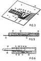
- the card readercomprises a bottom half-shell 45 having a rim 56 defining a front insertion slot 58 for the electronic memory card 52. This bottom half-shell also defines a housing 60 for receiving the electronic memory card while it is being processed.
- the card readeralso has a top half-shell 62 with a rim 64 that can be snap-fastened to the rim 56 of the bottom half-shell.
- the two half-shellshave portions in relief such as 66 and 68 enabling the electrical connector device 10 to be secured between the half-shells in such a manner that the housing 60 for an electronic memory card is defined by the bottom wall 66 of the bottom half-shell 54 and by the bottom face of the printed circuit board 12, this being the face of the board 12 through which the electrical contact springs 16 project, as can be more clearly in Figure 5.
- the board 12preferably has 2n slots 14, with the slots being disposed in a matrix of 2 rows by n columns.
- the connector devicehas only one contact spring.
- FIG 6there can be seen the body 60 of the key and the shank 62 thereof.
- the shankis slidably mounted in a cavity 64 of the key body.
- a mechanism(not shown) enables the shank 62 to be moved from a position in which it is retracted inside the body (out of service) and an extended position (for use).
- a portion of the bottom wall of the cavity 64is constituted by the electrical connector device 66.
- This deviceis constituted by a printed circuit 68 pierced by an orifice 70.
- the bottom face 68ahas a conductive track 72 connected to circuits 74 fixed on this face.
- a flexible springprojects via the orifice 70 from the top face 68b of the printed circuit. This spring 76 makes contact with the conductive track 80 on the shank 62 of the key.
Landscapes
- Engineering & Computer Science (AREA)
- Artificial Intelligence (AREA)
- Computer Vision & Pattern Recognition (AREA)
- Physics & Mathematics (AREA)
- General Physics & Mathematics (AREA)
- Theoretical Computer Science (AREA)
- Coupling Device And Connection With Printed Circuit (AREA)
Description
- The present invention relates to an electricalconnector device for co-operating with a removableelectronic medium, in particular an electronic memorycard, and to an electronic memory card reader using saidelectrical connector device.
- Electronic memory cards are being used more and morewidely, e.g. to give access to certain premises or toobtain certain services, or indeed to make certainpayments. An electronic memory card is essentiallyconstituted by a flat rectangular body in which anelectronic module is inserted, which module has externalelectrical contact areas on its outside face.
- To use such cards, it is necessary for a card to beinserted into a card reader which enables electricalconnection to be established between the various externalcontact areas on the card and the electronic circuits ofthe reader. Such electrical connections serve firstly toprovide electrical power to the integrated circuit of thecard, and secondly to transmit a certain amount ofinformation and instructions to and from the card.
- Given the wide variety of utilizations for suchcards, card readers must in turn be capable of acceptingvarious configurations depending on the utilization ofthe card. It is therefore advantageous to have cardreaders available that present configurations that differdepending on the utilization made thereof, such cardreaders generally be required to be as low-profile aspossible and also as low cost as possible.
- In particular, a card reader must include anelectrical connector device made up of a certain numberof flexible conductive springs which are disposed in sucha manner that each spring makes electrical contact withone of the external electrical contact areas of the cardwhen the card is inserted in the reader. These flexible electrical contacts are naturally designed to beconnected electrically to various electronic componentsof the reader to make it possible in particular to readthe information contained in the card or to writeinformation for the purpose of performing variousoperations, with the contacts also serving to supply thecard with electricity. It will be understood that it isadvantageous to have available an electrical connectordevice which is as highly integrated as possible insidethe reader and which is capable of being used indifferent reader configurations, which configurations mayhave respective special cases adapted to their functions.
- Circumstances other than readers also exist in whichit is necessary to establish an electrical connectionwith a removable electronic medium provided with at leastone external electrical contact area. This applies, forexample, to electronic keys.
- U.S. patent No. 4,675,516 discloses an electrical connector device for cooperationwith a removable electronic medium in the form of an electronic memory card.Further an isolating partition having electric contact elements mounted on a first faceis disclosed. The electrical contact element also referred to as a conductive leaf hasa flexible end which projects into an opening. The leaf transverses the opening in thepartition, and the free end of the leaf forms a contact surface. The contact elementcomprises at about its center an angled portion which is cemented in anotheropening in the partition. As far as the connection with a conductive strip is concerned,an angled end of the leaf penetrates a still further opening in the isolating partition,and is fixed in a conductive filling to electrically connect the leaf to said conductivestrip deposited on a second face of the partition.
- The object of the present invention is achieved by theelectrical connector device according to claim 1.
- It will be understood that by means of theelectrical connector device of the invention, in a cardreader, the flexible electrical springs for makingelectrical connection with the card are mounted directlyon the insulating board of the printed circuit whichitself receives at least some of the electroniccomponents of the card reader. This completelyeliminates the need to provide a particular mechanicalstructure including the resilient electrical contactsprings, said structure needing to be fitted to the boardand to be electrically connected to the electroniccomponents of the reader. It will be understood thatthis simplifies the structure of the reader and that itsthickness can be reduced very significantly, becausethere is no longer any separate mechanical structure forthe electrical connector device.
- Another object of the invention is to provide anelectronic memory card reader which uses the electricalconnector device of the type defined above.
- The invention will be better understood on readingthe following description of an embodiment of theinvention given by way of non-limiting example. Thedescription refers to the accompanying figures, in which:
- Figure 1 is a simplified exploded view of theelectrical connector device having a plurality ofelectrical contacts;
- Figure 2 is a perspective view showing theconductive springs mounted on the printed circuit board;
- Figure 3 is a perspective view of a completeelectrical connector device;
- Figure 4 is an exploded view of an electronic memorycard reader using the electrical connector device ofFigures 1 to 3;
- Figure 5 is a longitudinal vertical section view ofan electronic memory card reader of the kind shown inFigure 4; and
- Figure 6 is a vertical section view of an electronickey using the connector device.
- With reference initially to Figures 1 and 2, therefollows a description of the principles of the electronicconnector device as applied to electronic memory cards.
- The device comprises a
board 12 of insulatingmaterial of the type used for printed circuits. Thisboard is of sufficient strength. Slots such as 14 areformed through theboard 12 in positions that correspondto the positions of the external electrical contact areasof the electronic memory card. In the most commonconfiguration, theseslots 14 are thus disposed in a 2 x4 matrix. In Figure 1, there can thus be seen slots 14.1to 14.8. Each of these slots is designed to receive aportion of an electrical connector element givenoverallreference 16. Each electrical connector element isconstituted by a resilient spring of conductive material,e.g. copper or brass. Theconnector element 16 has afirst end 18 for connection and fixing purposes, a foldedintermediate zone 20 constituting a zone for makingcontact with the external contact areas of an electronicmemory card, and afree end 22 that is substantiallyplane. Eachslot 14 is associated with anelectricalconnection tab 24 designed to receive the fixingend 18of the corresponding connector element. When the fixingportion 18 is soldered to thetab 24 the angled portionof theelectrical contact 20 passes through thecorrespondingslot 14 and projects from the bottom faceof theboard 12. When thespring 16 is not deformed, itsfree end 22 presses against the top face of theplate 12. - Figure 2 shows the various
electrical connectorelements 14 soldered to the tabs of the insulatingboard 12. - It will be understood that by means of thisparticular disposition, the insulating printed
circuitboard 12 performs two functions. Firstly it serves as amechanical support and as a support for positioning thevariouselectrical connector elements 16, and secondly itacts as a printed circuit insofar as it is possible, asexplained below, to provide conductive tracks forconnecting thecontact tabs 24 to various electroniccomponents also mounted on theboard 12 and constitutingthe circuits of the reader in which the electricalconnector device is integrated. - Two
additional slots board 12, withresilientelements conductive springs - It will be understood that when an electronic memorycard is inserted in the reader, as explained below, thethickness of the card causes the
contact zones 20 of theconnector elements 16 to be raised. Because of theresilience of the springs and because the ends 22 thereofare not secured to the printed circuit board, goodelectrical contact is indeed obtained with pressure beingapplied between theelectrical connector elements 16 andthe external connection areas of the electronic memorycard. - Figure 3 shows the printed
circuit board 12 ingreater detail, its flexibleconductive springs 16 beingfixed to their contact tabs and various conductive tracks such as 40, 42, and 44 enabling the various electricalcontact elements to be connected to the connection areas45 of electronic components mounted on the printedcircuit 12. - With reference now to Figures 4 and 5, an embodimentof an electronic memory card reader is described thatmakes use of an
electrical connector device 10 of thetype described above. - Figure 4 shows the
electrical connector device 10constituted by the printedcircuit board 12 and itsflexible electrical contact springs 16 together withvarious electronic components A, B, and C which areconnected to one another and/or to theelectricalcontacts 16 via conductive tracks formed on theinsulatingboard 12 by deposited conductor material. Forexample, the component C may be a liquid crystal displayfor displaying information relating to use of theelectronic memory card or to its state. In this figure,there can also be seen other component parts of thecardreader 50, and the memory card itself is referenced 52.The card reader comprises a bottom half-shell 45 having arim 56 defining afront insertion slot 58 for theelectronic memory card 52. This bottom half-shell alsodefines ahousing 60 for receiving the electronic memorycard while it is being processed. - The card reader also has a top half-
shell 62 with arim 64 that can be snap-fastened to therim 56 of thebottom half-shell. As shown more clearly in Figure 5,the two half-shells have portions in relief such as 66and 68 enabling theelectrical connector device 10 to besecured between the half-shells in such a manner that thehousing 60 for an electronic memory card is defined bythebottom wall 66 of the bottom half-shell 54 and by thebottom face of the printedcircuit board 12, this beingthe face of theboard 12 through which the electricalcontact springs 16 project, as can be more clearly inFigure 5. - The
board 12 preferably has 2nslots 14, with theslots being disposed in a matrix of 2 rows byn columns. - With reference now to Figure 6, a particular use ofthe electrical connector device for implementing anelectronic key is described. In this embodiment, theconnector device has only one contact spring.
- In Figure 6, there can be seen the
body 60 of thekey and theshank 62 thereof. The shank is slidablymounted in acavity 64 of the key body. A mechanism (notshown) enables theshank 62 to be moved from a positionin which it is retracted inside the body (out of service)and an extended position (for use). - A portion of the bottom wall of the
cavity 64 isconstituted by theelectrical connector device 66. Thisdevice is constituted by a printedcircuit 68 pierced byanorifice 70. The bottom face 68a has aconductivetrack 72 connected tocircuits 74 fixed on this face. - A flexible spring projects via the
orifice 70 fromthetop face 68b of the printed circuit. Thisspring 76makes contact with theconductive track 80 on theshank 62 of the key.
Claims (6)
- An electrical connector device 10 for co-operating with aremovable electronic medium (52) provided with at least oneexternal electrical contact area, the device (10) comprising:a board (12) of insulating material having a first faceand a second face and provided with at least one slot (14);at least one electrical connector element (16) in theform of a resilient conductive spring; each electricalconnector element (16) having a fixing end (18) and a contact zone (20)for contacting one of the external contact areas of saidmedium;at least one electrical connection tab (24), said at least oneconnection tab (24) being disposed on the first face of saidboard (12) close to said at least one slot (14);at least one conductive track (40) formed on the firstface of the board (12) to connect said connection tab (24)electrically to at least one contact terminal;said at least one electrical connector element (16) being fixed to said at least oneelectrical connection tab (24) via its fixing end (18), the contact zone orportion (20) of each connector element (16) projecting from thesecond face of said board (12) by passing through said slot, andwherein each electrical connector element (16) comprises aplanar portion forming the fixing end (18), a foldedintermediate portion (20) forming the contact zone, and asecond planar end designed to bear against the top face ofsaid board (12) when the electrical connector element (16) is notelastically deformed.
- An electrical connector device according to claim 1,further comprising at least one electronic component (A, B, C)fixed on said first face and connected to said at least oneelectrical connector element (16).
- An electrical connector device according to claim 1,having a plurality of slots (14.1-14.8), a plurality of electricalconnector elements (16), and a plurality of conductive tracks (40, 42, 44).
- An electrical connector device according to claim 1,wherein said board (12) has 2n slots, the slots being disposedin a matrix of 2 rows byn columns.
- An electrical connector device according to claim 4,wherein said insulating board (12) has an additional slot (26)provided with an additional electrical connector elementforming an end-of-stroke detector.
- An electrical memory card reader using an electricalconnector device according to one of claims 1-5, the readercomprising:a top half-shell;a bottom half-shell defining an insertion slot foran electronic memory card and an internal housing forreceiving said card; andmeans for fixing the insulating board of saidelectrical connector device between said half-shells.
Applications Claiming Priority (2)
| Application Number | Priority Date | Filing Date | Title |
|---|---|---|---|
| FR9715203AFR2771834B1 (en) | 1997-12-03 | 1997-12-03 | ELECTRICAL CONNECTION DEVICE FOR COOPERATING WITH A MOBILE ELECTRONIC MEDIUM |
| FR9715203 | 1997-12-03 |
Publications (2)
| Publication Number | Publication Date |
|---|---|
| EP0921490A1 EP0921490A1 (en) | 1999-06-09 |
| EP0921490B1true EP0921490B1 (en) | 2004-09-01 |
Family
ID=9514088
Family Applications (1)
| Application Number | Title | Priority Date | Filing Date |
|---|---|---|---|
| EP98122985AExpired - LifetimeEP0921490B1 (en) | 1997-12-03 | 1998-12-03 | Electrical connector device for co-operating with a removable electronic medium |
Country Status (5)
| Country | Link |
|---|---|
| US (1) | US6086425A (en) |
| EP (1) | EP0921490B1 (en) |
| JP (1) | JPH11242721A (en) |
| DE (1) | DE69825962T2 (en) |
| FR (1) | FR2771834B1 (en) |
Families Citing this family (11)
| Publication number | Priority date | Publication date | Assignee | Title |
|---|---|---|---|---|
| WO2000041126A1 (en)* | 1998-12-31 | 2000-07-13 | Amphenol-Tuchel Electronics Gmbh | Universal switch for a smart card reader |
| TW563941U (en)* | 2001-04-30 | 2003-11-21 | Hon Hai Prec Ind Co Ltd | Electronic card connector |
| TW554592B (en)* | 2002-08-13 | 2003-09-21 | Carry Computer Eng Co Ltd | Connector module for tray-like electric memory card |
| TWI253793B (en)* | 2003-03-21 | 2006-04-21 | Hon Hai Prec Ind Co Ltd | Switching terminal and method for making the same |
| TW575242U (en)* | 2003-06-17 | 2004-02-01 | Molex Taiwan Ltd | Electronic card connector |
| TWM255560U (en)* | 2004-04-22 | 2005-01-11 | Tai Sol Electronics Co Ltd | Multi in one card connector with common terminal pins |
| EP2000945B1 (en)* | 2007-06-01 | 2010-08-04 | ddm hopt + schuler GmbH & Co. KG. | Tamper proof card reader |
| US7909657B1 (en) | 2009-11-12 | 2011-03-22 | Hubbell Incorporated | Electrical connector with low-stress, reduced-electrical-length contacts |
| US9590331B2 (en)* | 2014-10-28 | 2017-03-07 | Kabushiki Kaisha Toshiba | Card connector |
| EP3051635B1 (en)* | 2015-01-30 | 2018-01-17 | TE Connectivity Germany GmbH | Electric contact means and electrical cable assembly for the automotive industry |
| US11239587B2 (en)* | 2018-03-07 | 2022-02-01 | Xcelsis Corporation | Configurable smart object system with clip-based connectors |
Citations (1)
| Publication number | Priority date | Publication date | Assignee | Title |
|---|---|---|---|---|
| US4675516A (en)* | 1983-10-27 | 1987-06-23 | Flonic | Apparatus for reading electronic memory cards |
Family Cites Families (5)
| Publication number | Priority date | Publication date | Assignee | Title |
|---|---|---|---|---|
| DE3943703C2 (en)* | 1989-09-21 | 2001-06-21 | Amphenol Tuchel Elect | Smart card reader |
| DE4118312C2 (en)* | 1991-06-04 | 1995-03-09 | Amphenol Tuchel Elect | Contact set for a card with contact zones |
| FR2681711B1 (en)* | 1991-09-20 | 1996-08-02 | Itt Composants Instr | PORTABLE CASE FOR AN ELECTRONIC MEMORY CARD |
| FR2733358B1 (en)* | 1995-04-21 | 1997-05-30 | Itt Composants Instr | ELECTRICAL CONNECTOR, PARTICULARLY FOR CONNECTING AN ELECTRONIC MEMORY CARD |
| DE19524536C1 (en)* | 1995-07-05 | 1996-10-02 | Preh Elektro Feinmechanik | Chip card reader for telephone cards, credit cards, or patient cards etc |
- 1997
- 1997-12-03FRFR9715203Apatent/FR2771834B1/ennot_activeExpired - Fee Related
- 1998
- 1998-12-02USUS09/203,743patent/US6086425A/ennot_activeExpired - Fee Related
- 1998-12-03DEDE69825962Tpatent/DE69825962T2/ennot_activeExpired - Fee Related
- 1998-12-03EPEP98122985Apatent/EP0921490B1/ennot_activeExpired - Lifetime
- 1998-12-03JPJP10344539Apatent/JPH11242721A/enactivePending
Patent Citations (1)
| Publication number | Priority date | Publication date | Assignee | Title |
|---|---|---|---|---|
| US4675516A (en)* | 1983-10-27 | 1987-06-23 | Flonic | Apparatus for reading electronic memory cards |
Also Published As
| Publication number | Publication date |
|---|---|
| DE69825962D1 (en) | 2004-10-07 |
| FR2771834A1 (en) | 1999-06-04 |
| EP0921490A1 (en) | 1999-06-09 |
| DE69825962T2 (en) | 2005-09-08 |
| US6086425A (en) | 2000-07-11 |
| FR2771834B1 (en) | 2000-01-21 |
| JPH11242721A (en) | 1999-09-07 |
Similar Documents
| Publication | Publication Date | Title |
|---|---|---|
| US4725924A (en) | Electronic unit especially for microcircuit cards and card comprising such a unit | |
| KR100675206B1 (en) | Adapter for card connection | |
| US6179649B1 (en) | SIM card incorporated in battery pack of terminal | |
| US7175084B2 (en) | Integrated circuit card and case therefor | |
| JPH0831120B2 (en) | Portable electronic card receiving device | |
| US6296491B1 (en) | Card edge connector incorporating hot plug switch | |
| US6835100B1 (en) | Multi-in-one connector structure | |
| EP0921490B1 (en) | Electrical connector device for co-operating with a removable electronic medium | |
| US20030119364A1 (en) | Electronic card connector having improved assembly | |
| WO2000013126A1 (en) | Pcmcia smart card reader | |
| US6557761B1 (en) | Card detect switch for card connector | |
| EP1212723A1 (en) | Carrier element for an electronic media apparatus | |
| EP1059600B1 (en) | Portable smart card reader assembly | |
| JPH1186978A (en) | Electric connector for ic card | |
| KR100361055B1 (en) | Portable electronic device | |
| KR100552322B1 (en) | Electrical connector | |
| EP0926617B1 (en) | A smart card reader | |
| CN109787049B (en) | Stack type two-in-one card holder and electronic equipment | |
| JP3816209B2 (en) | Portable electronic devices | |
| JPH0935031A (en) | Contact part for contact unit | |
| JP3532123B2 (en) | Card with integrated circuit | |
| KR100533651B1 (en) | Chipcard-Type Combi-Card, Combi-Card Connector For The Same, and RF Electronic-Paying Device Using The Same | |
| JPH048596A (en) | Ic memory card | |
| JPH10255928A (en) | Connector for ic card | |
| KR20060125698A (en) | Memory pack |
Legal Events
| Date | Code | Title | Description |
|---|---|---|---|
| PUAI | Public reference made under article 153(3) epc to a published international application that has entered the european phase | Free format text:ORIGINAL CODE: 0009012 | |
| AK | Designated contracting states | Kind code of ref document:A1 Designated state(s):BE DE FR GB IT NL SE | |
| AX | Request for extension of the european patent | Free format text:AL;LT;LV;MK;RO;SI | |
| 17P | Request for examination filed | Effective date:19991129 | |
| AKX | Designation fees paid | Free format text:BE DE FR GB IT NL SE | |
| 17Q | First examination report despatched | Effective date:20030116 | |
| GRAP | Despatch of communication of intention to grant a patent | Free format text:ORIGINAL CODE: EPIDOSNIGR1 | |
| GRAS | Grant fee paid | Free format text:ORIGINAL CODE: EPIDOSNIGR3 | |
| GRAA | (expected) grant | Free format text:ORIGINAL CODE: 0009210 | |
| AK | Designated contracting states | Kind code of ref document:B1 Designated state(s):BE DE FR GB IT NL SE | |
| PG25 | Lapsed in a contracting state [announced via postgrant information from national office to epo] | Ref country code:NL Free format text:LAPSE BECAUSE OF FAILURE TO SUBMIT A TRANSLATION OF THE DESCRIPTION OR TO PAY THE FEE WITHIN THE PRESCRIBED TIME-LIMIT Effective date:20040901 Ref country code:IT Free format text:LAPSE BECAUSE OF FAILURE TO SUBMIT A TRANSLATION OF THE DESCRIPTION OR TO PAY THE FEE WITHIN THE PRESCRIBED TIME-LIMIT;WARNING: LAPSES OF ITALIAN PATENTS WITH EFFECTIVE DATE BEFORE 2007 MAY HAVE OCCURRED AT ANY TIME BEFORE 2007. THE CORRECT EFFECTIVE DATE MAY BE DIFFERENT FROM THE ONE RECORDED. Effective date:20040901 Ref country code:BE Free format text:LAPSE BECAUSE OF FAILURE TO SUBMIT A TRANSLATION OF THE DESCRIPTION OR TO PAY THE FEE WITHIN THE PRESCRIBED TIME-LIMIT Effective date:20040901 | |
| REG | Reference to a national code | Ref country code:GB Ref legal event code:FG4D | |
| REF | Corresponds to: | Ref document number:69825962 Country of ref document:DE Date of ref document:20041007 Kind code of ref document:P | |
| PG25 | Lapsed in a contracting state [announced via postgrant information from national office to epo] | Ref country code:SE Free format text:LAPSE BECAUSE OF FAILURE TO SUBMIT A TRANSLATION OF THE DESCRIPTION OR TO PAY THE FEE WITHIN THE PRESCRIBED TIME-LIMIT Effective date:20041201 | |
| NLV1 | Nl: lapsed or annulled due to failure to fulfill the requirements of art. 29p and 29m of the patents act | ||
| PLBE | No opposition filed within time limit | Free format text:ORIGINAL CODE: 0009261 | |
| STAA | Information on the status of an ep patent application or granted ep patent | Free format text:STATUS: NO OPPOSITION FILED WITHIN TIME LIMIT | |
| ET | Fr: translation filed | ||
| 26N | No opposition filed | Effective date:20050602 | |
| PGFP | Annual fee paid to national office [announced via postgrant information from national office to epo] | Ref country code:GB Payment date:20071106 Year of fee payment:10 | |
| PGFP | Annual fee paid to national office [announced via postgrant information from national office to epo] | Ref country code:DE Payment date:20071228 Year of fee payment:10 | |
| PGFP | Annual fee paid to national office [announced via postgrant information from national office to epo] | Ref country code:FR Payment date:20071204 Year of fee payment:10 | |
| GBPC | Gb: european patent ceased through non-payment of renewal fee | Effective date:20081203 | |
| REG | Reference to a national code | Ref country code:FR Ref legal event code:ST Effective date:20090831 | |
| PG25 | Lapsed in a contracting state [announced via postgrant information from national office to epo] | Ref country code:DE Free format text:LAPSE BECAUSE OF NON-PAYMENT OF DUE FEES Effective date:20090701 | |
| PG25 | Lapsed in a contracting state [announced via postgrant information from national office to epo] | Ref country code:GB Free format text:LAPSE BECAUSE OF NON-PAYMENT OF DUE FEES Effective date:20081203 | |
| PG25 | Lapsed in a contracting state [announced via postgrant information from national office to epo] | Ref country code:FR Free format text:LAPSE BECAUSE OF NON-PAYMENT OF DUE FEES Effective date:20081231 |