EP0920073A1 - Multi-filar helix antennae - Google Patents
Multi-filar helix antennaeDownload PDFInfo
- Publication number
- EP0920073A1 EP0920073A1EP98660110AEP98660110AEP0920073A1EP 0920073 A1EP0920073 A1EP 0920073A1EP 98660110 AEP98660110 AEP 98660110AEP 98660110 AEP98660110 AEP 98660110AEP 0920073 A1EP0920073 A1EP 0920073A1
- Authority
- EP
- European Patent Office
- Prior art keywords
- antenna
- coefficient
- helical
- elements
- axial
- Prior art date
- Legal status (The legal status is an assumption and is not a legal conclusion. Google has not performed a legal analysis and makes no representation as to the accuracy of the status listed.)
- Granted
Links
- 238000010295mobile communicationMethods0.000claimsdescription3
- 239000003989dielectric materialSubstances0.000claimsdescription2
- 238000004519manufacturing processMethods0.000claimsdescription2
- 238000000034methodMethods0.000claimsdescription2
- 230000004323axial lengthEffects0.000abstractdescription6
- 238000004891communicationMethods0.000description6
- 230000005540biological transmissionEffects0.000description2
- 238000013461designMethods0.000description2
- 239000002184metalSubstances0.000description2
- 239000007787solidSubstances0.000description2
- 239000012141concentrateSubstances0.000description1
- 238000011161developmentMethods0.000description1
- 230000018109developmental processEffects0.000description1
- 230000000694effectsEffects0.000description1
- 238000005530etchingMethods0.000description1
- 210000001652frontal lobeAnatomy0.000description1
- 238000012886linear functionMethods0.000description1
- 238000012986modificationMethods0.000description1
- 230000004048modificationEffects0.000description1
- 230000010363phase shiftEffects0.000description1
Images


Classifications
- H—ELECTRICITY
- H01—ELECTRIC ELEMENTS
- H01Q—ANTENNAS, i.e. RADIO AERIALS
- H01Q11/00—Electrically-long antennas having dimensions more than twice the shortest operating wavelength and consisting of conductive active radiating elements
- H01Q11/02—Non-resonant antennas, e.g. travelling-wave antenna
- H01Q11/08—Helical antennas
Definitions
- the present inventionrelates to multi-filar helix antennae and in particular, though not necessarily, to quadrifilar helix antennae.
- GPSGlobal Positioning System
- TMINMARSAT
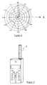
- the QFH antenna 1comprises four regular and identical inter-wound resonant helical elements 2a to 2d, centered on a common axis A and physically offset from one another by 90°.
- signals received from the four helical elementsare phase shifted by 0°, 90°,180°, and 270° respectively prior to combining them in the RF receiving unit of the mobile device.
- the signal to be transmittedis split into four components, having relative phase shifts of 0°,90°,180°, and 270° respectively, which are then applied to the helical elements 2a to 2d.
- the QFH antennahas proved suitable for satellite communication for three main reasons. Firstly it is relatively compact (compared to other useable antennae), a property which is essential if it is to be used in a portable device. Secondly, the QFH antenna is able to transmit and receive circularly polarised signals so that rotation of the direction of polarisation (due to for example to movement of the satellite) does not significantly affect the signal energy available to the antenna. Thirdly, it has a spatial gain pattern (in both transmission and reception modes) with a main forward lobe which extends over a generally hemispherical region. This gain pattern is illustrated in Figure 2 for the antenna of Figure 1, at an operating frequency of 1.7GHz. Thus, the QFH antenna is well suited for communicating with satellites which are located in the hemispherical region above the head of the user.
- a problem with the QFH antennahowever remains it's large size. If this can be reduced, then the market for mobile satellite communications devices is likely to be increased considerably.
- One way to reduce the length of a QFH antenna for a given frequency bandis to reduce the pitch of the helical elements. However, this tends to increase the horizontal gain of the antenna at the expense of the vertical gain, shifting the gain pattern further from the ideal hemisphere.
- Another way to reduce the length of the antennais to form the helical elements around a solid dielectric core. However, this not only increases the weight of the antenna, it introduces losses which reduce the antenna gain.
- a multi-filar helix antennahaving a plurality of inter-wound helical antenna elements, each helical element being defined by an axial coefficient z , a radial coefficient r, and an angular coefficient ⁇ , wherein d ⁇ / dz for at least one of the helices is non-linear with respect to the axial coefficient z .
- the present inventionintroduces into the design of multi-filar helix antennae a variable which has not previously been applied.
- the spatial gain pattern of the antennamay be optimised.
- the axial length of the antennamay be reduced.
- d ⁇ / dz for all of the helical elementsis non-linear with respect to the axial coefficient z . More preferably, d ⁇ / dz varies, with respect to z , substantially identically for all of the helical elements.
- d ⁇ / dz for said at least one helical elementvaries periodically. More preferably, the period of this variation is an integer fraction of one turn length of the helical element. Alternatively, the period may be an integer multiple of the turn length.
- the functions fmay be multiplying constants.
- the radial coefficient ris constant with respect to the axial coefficient z for all of the helical elements.
- the helical elementsmay be provided around the periphery of a cylindrical core.
- rmay vary with respect to z .
- rmay vary linearly with respect to z for one or more of the helical elements, e.g. by providing the or each helical element around the periphery of a frusto-cone.
- the coremay be solid, but is preferably hollow in order to reduce the weight of the antenna.
- a hollow coremay comprise a coiled sheet of dielectric material.
- the helical elementsmay be metal wire strands wound around the core, metal tracks formed by etching or growth, or have any other suitable structure.
- the properties of the antennamay be adjusted by forming throughholes in the core or by otherwise modifying the dielectric properties of the core.
- the multi-filar helix antennais a quadrifilar helix antenna, having four helical antenna elements.
- the antenna elementsare preferably spaced at 90° intervals although other spacings may be selected.
- Non-linearitymay be introduced into one or more of the helical elements in order to improve the approximation of the main frontal lobe of the antenna gain pattern to a hemisphere, and to reduce back lobes of the gain pattern, or to tailor the gain pattern to any other desired shape.
- the inventionapplies also to other multi-filar antennae such as bi-filar antennae.
- Multi-filar antennae embodying the present inventionmay be arranged in use to be either back-fired or end-fired by appropriate phasing of the helical elements.
- a mobile communication devicecomprising a multi-filar antenna according to the above first aspect of the present invention.
- the deviceis preferably arranged to communicate with a satellite. More preferably, the device is a satellite telephone.
- a method of manufacturing a multi-filar helical antenna having a plurality of helical antenna elementscomprising the steps of:
- ⁇the angular coefficient
- Figure 3Awhich effectively shows the helical elements uncoiled.
- the vertical axistherefore corresponds to z whilst the horizontal axis is proportional to the angular coefficient ⁇ (the dimensions on both axes are millimeters).
- the axial length z of the antenna of Figures 1 and 3Ais 15.37cm, the radius r is 0.886cm, and the number of turns N is 1.2.
- the axial coefficientcan be described by: where a,b,c, and d are constants which control the non-linearity of the helical element and l ax is the axial length of the element.
- a,ccan be thought of as the amplitude of the non-linear variation whilst b,d can be thought of as the period of the variation.
- the rate of change of ⁇ with respect to z , d ⁇ / dzbecomes non-linear with respect to z , as a result of the sinusoidal variation introduced into z .
- the helical elementis linear, i.e. as in the antenna of Figures 1 and 3A.
- the tablealso shows the coefficients of the linear antenna of Figure 3A for comparison. Fig.
- the axial lengths l ax of the QFH antennaeare also included in the above table, from which it is apparent that where non-linearity is introduced into either pitch or shape, the axial length of the antenna is reduced for a given radius and number of turns.
- Figure 4shows the spatial gain pattern for the QFH antenna of Figure 3B at 1.7GHz. Comparison with the gain pattern of the antenna of Figure 3A, shown in Figure 2, shows that the introduction of non-linearity into the helical elements reduces the gain in the axial direction by ⁇ 2.5dB. However, this reduction is compensated for by a reduction in the length of the antenna by 1.57cm. Where the QFH antenna is designed to communicate with satellites in low earth orbits, the distortion of the gain pattern may even be advantageous.
- Figure 5shows a phone having a multi-filar helix antenna 5 according to the invention.
- the phonecan be e.g. a mobile communication device such as a mobile phone, or a satellite telephone.
Landscapes
- Details Of Aerials (AREA)
- Variable-Direction Aerials And Aerial Arrays (AREA)
- Support Of Aerials (AREA)
- Mobile Radio Communication Systems (AREA)
Abstract

Description
- The present invention relates to multi-filar helix antennae and in particular,though not necessarily, to quadrifilar helix antennae.
- A number of satellite communication systems are today in operation whichallow users to communicate via satellite using only portable communicationdevices. These include the Global Positioning System (GPS) which providespositional and navigational information to earth stations, and telephonesystems such as INMARSAT (TM). Demand for this type of personalcommunication via satellite (S-PCN) is expected to grow significantly in thenear future.
- One area which is of major importance is the development of a suitableantenna which can communicate bi-directionally with a relatively remoteorbiting satellite with a satisfactory signal to noise ratio. Work in this area hastended to concentrate on the quadrifilar helix (QFH) antenna (K. Fujimoto andJ.K. James, "Mobile Antenna Systems Handbook", Norwood, 1994, ArtechHouse). As is illustrated in Figure 1, the
QFH antenna 1 comprises fourregular and identical inter-wound resonanthelical elements 2a to 2d, centeredon a common axis A and physically offset from one another by 90°. Inreception mode, signals received from the four helical elements are phaseshifted by 0°, 90°,180°, and 270° respectively prior to combining them in theRF receiving unit of the mobile device. Similarly, in transmission mode, thesignal to be transmitted is split into four components, having relative phaseshifts of 0°,90°,180°, and 270° respectively, which are then applied to thehelical elements 2a to 2d. - The QFH antenna has proved suitable for satellite communication for threemain reasons. Firstly it is relatively compact (compared to other useableantennae), a property which is essential if it is to be used in a portable device.Secondly, the QFH antenna is able to transmit and receive circularly polarisedsignals so that rotation of the direction of polarisation (due to for example tomovement of the satellite) does not significantly affect the signal energyavailable to the antenna. Thirdly, it has a spatial gain pattern (in both transmission and reception modes) with a main forward lobe which extendsover a generally hemispherical region. This gain pattern is illustrated inFigure 2 for the antenna of Figure 1, at an operating frequency of 1.7GHz.Thus, the QFH antenna is well suited for communicating with satellites whichare located in the hemispherical region above the head of the user.
- A problem with the QFH antenna however remains it's large size. If this canbe reduced, then the market for mobile satellite communications devices islikely to be increased considerably. One way to reduce the length of a QFHantenna for a given frequency band is to reduce the pitch of the helicalelements. However, this tends to increase the horizontal gain of the antennaat the expense of the vertical gain, shifting the gain pattern further from theideal hemisphere. Another way to reduce the length of the antenna is to formthe helical elements around a solid dielectric core. However, this not onlyincreases the weight of the antenna, it introduces losses which reduce theantenna gain.
- It is an object of the present invention to improve the design flexibility of multi-filarhelix antennae to allow gain patterns to be tailored for particularapplications. It is also an object of the present invention to reduce the lengthof QFH antennae used for satellite communication.
- According to a first aspect of the present invention there is provided a multi-filarhelix antenna having a plurality of inter-wound helical antenna elements,each helical element being defined by an axial coefficientz, a radialcoefficient r, and an angular coefficient , whereind/dz for at least one ofthe helices is non-linear with respect to the axial coefficientz.
- The present invention introduces into the design of multi-filar helix antennae avariable which has not previously been applied. By carefully introducing non-linearchanges into the structure of a helical element of the multi-filar helix antenna, the spatial gain pattern of the antenna may be optimised. Moreover,the axial length of the antenna may be reduced.
- Preferably,d/dz for all of the helical elements is non-linear with respect tothe axial coefficientz. More preferably,d /dz varies, with respect toz,substantially identically for all of the helical elements.
- Preferably,d/dz for said at least one helical element varies periodically.More preferably, the period of this variation is an integer fraction of one turnlength of the helical element. Alternatively, the period may be an integermultiple of the turn length.
- Preferably, the axial coefficientz is a sinusoidal function of the angularcoefficient , i.e.z =k0 +f sin(k1) wherek0 andk1 are constants. Theaxial coefficientz may be a sum of multiple sinusoidal functions of theangular coefficient, i.e.z =k0 +f1 sin(k1)+...+fn sin(kn). The functionsf may be multiplying constants.
- Preferably, the radial coefficient r is constant with respect to the axialcoefficientz for all of the helical elements. The helical elements may beprovided around the periphery of a cylindrical core. Alternatively, r may varywith respect toz. For example, r may vary linearly with respect toz for oneor more of the helical elements, e.g. by providing the or each helical elementaround the periphery of a frusto-cone. In either case, the core may be solid,but is preferably hollow in order to reduce the weight of the antenna. A hollowcore may comprise a coiled sheet of dielectric material. The helical elementsmay be metal wire strands wound around the core, metal tracks formed byetching or growth, or have any other suitable structure. The properties of theantenna may be adjusted by forming throughholes in the core or by otherwisemodifying the dielectric properties of the core.
- Preferably, the multi-filar helix antenna is a quadrifilar helix antenna, havingfour helical antenna elements. The antenna elements are preferably spacedat 90° intervals although other spacings may be selected. Non-linearity maybe introduced into one or more of the helical elements in order to improve theapproximation of the main frontal lobe of the antenna gain pattern to ahemisphere, and to reduce back lobes of the gain pattern, or to tailor the gainpattern to any other desired shape. The invention applies also to other multi-filarantennae such as bi-filar antennae.
- Multi-filar antennae embodying the present invention may be arranged in useto be either back-fired or end-fired by appropriate phasing of the helicalelements.
- According to a second aspect of the present invention there is provided amobile communication device comprising a multi-filar antenna according tothe above first aspect of the present invention. The device is preferablyarranged to communicate with a satellite. More preferably, the device is asatellite telephone.
- According to a third aspect of the present invention there is provided amethod of manufacturing a multi-filar helical antenna having a plurality ofhelical antenna elements, the method comprising the steps of:
- forming a plurality of elongate conducting antenna elements on asurface of a substantially planar dielectric sheet, at least one of said elementsbeing non-linear; and
- subsequently coiling said sheet into a cylinder with said antennaelements being on the outer surface of the cylinder.
- For a better understanding of the present invention and in order to show howthe same may be carried into effect, reference will now be made, by way ofexample, to the accompanying drawings, in which:
- Figure 1 illustrates a quadrifilar helix antenna according to the prior art;
- Figure 2 illustrates the spatial gain pattern, in cross-section, of thequadrifilar helix antenna of Figure 1;
- Figures 3A to 3D show axial coefficientz versus angular coefficient for respective helical antenna elements;
- Figure 4 illustrates the spatial gain pattern, in cross-section, of thequadrifilar helix antenna constructed according to Figure 3B; and
- Figure 5 shows a phone having a multi-filar helix antenna according tothe invention.
- There has already been described, with reference to Figure 1, a conventionalquadrifilar helix antenna. The antenna is formed from four regular
helicalelements 2a to 2d where, for each element, the axial coefficientz is a linearfunction of the angular coefficient , i.e.z =k wherek is a constant. Thisis illustrated in two-dimensions in Figure 3A, which effectively shows thehelical elements uncoiled. The vertical axis therefore corresponds toz whilstthe horizontal axis is proportional to the angular coefficient (the dimensionson both axes are millimeters). The axial lengthz of the antenna of Figures 1and 3A is 15.37cm, the radiusr is 0.886cm, and the number of turnsN is1.2. - In order to add non-linearity to the helical element, the axial coefficient can bedescribed by:wherea,b,c, andd are constants which control the non-linearity of thehelical element andlax is the axial length of the element.a,c can be thoughtof as the amplitude of the non-linear variation whilstb,d can be thought of asthe period of the variation. The rate of change of with respect toz,d/dz,becomes non-linear with respect toz, as a result of the sinusoidal variationintroduced intoz. Witha,b,c, andd equal to zero, then the helical elementis linear, i.e. as in the antenna of Figures 1 and 3A.

- Figures 3B to 3D show two-dimensional representations for QFH antennaewith non-linear helical elements and which can be described with the aboveexpression, where the coefficientsa,b,c, andd have the values shown inthe following table, the number of turns is fixed atN = 1.2, and the radiusris fixed at 0.886cm. These antennae are designed to operate at 1.7GHz.The table also shows the coefficients of the linear antenna of Figure 3A forcomparison.
Fig. lax(cm) N r(cm) a b c d f0(GHz) 3A 15.37 1.2 0.886 0 0 0 0 1.7 3B 13.8 1.2 0.886 0 0 5 5 1.7 3C 14.7 1.2 0.886 19 1 0 0 1.7 3D 13.0 1.2 0.886 5 1 3 9 1.7 - Also included in the above table are the axial lengths lax of the QFH antennae,from which it is apparent that where non-linearity is introduced into either pitchor shape, the axial length of the antenna is reduced for a given radius andnumber of turns.
- Figure 4 shows the spatial gain pattern for the QFH antenna of Figure 3B at1.7GHz. Comparison with the gain pattern of the antenna of Figure 3A,shown in Figure 2, shows that the introduction of non-linearity into the helicalelements reduces the gain in the axial direction by ∼2.5dB. However, thisreduction is compensated for by a reduction in the length of the antenna by1.57cm. Where the QFH antenna is designed to communicate with satellitesin low earth orbits, the distortion of the gain pattern may even beadvantageous.
- Figure 5 shows a phone having a
multi-filar helix antenna 5 according to theinvention. The phone can be e.g. a mobile communication device such as amobile phone, or a satellite telephone. - It will be appreciated that various modifications may be made to the abovedescribed embodiments without departing from the scope of the presentinvention.

Claims (14)
- A multi-filar helix antenna having a plurality of inter-twined helicalantenna elements, each helical element being defined by an axial coefficientz, a radial coefficient r, and an angular coefficient , whereind/dz for atleast one of the helices is non-linear with respect to the axial coefficientz.
- An antenna according to claim 1, whereind/dz for all of the helicalelements is non-linear with respect to the axial coefficientz.
- An antenna according to claim 2, whereind/dz varies, with respect toz, substantially identically for all of the helical elements.
- An antenna according to any one of the preceding claims, whereind/dz for said at least one helical element, varies periodically.
- An antenna according to claim 4, wherein the period of this variation isan integer fraction of one turn length of the helical element or the period is aninteger multiple of the turn length.
- An antenna according to claim 5, wherein, for said at least oneelement, the axial coefficientz is a sinusoidal function of the angularcoefficient , i.e.z =k0 +f sin(k1) wherek0 andk1 are constants.
- An antenna according to claim 5 or 6, wherein the axial coefficientz isa sum of multiple sinusoidal functions of the angular coefficient, i.e.z =k0 +f1 sin(k1) +f2 sin(k2)+...+fn sin(kn).
- An antenna according to any one of the preceding claims, wherein theradial coefficient r is constant with respect to the axial coefficientz for all ofthe helical elements.
- An antenna according to claim 8, wherein the helical elements areprovided around the periphery of a cylindrical core.
- An antenna according to claim 9, wherein said core is hollow andcomprises one or more coiled sheets of dielectric material.
- An antenna according to any one of the preceding claims, the antennabeing a quadrifilar helix antenna, having four helical antenna elements.
- A mobile communication device comprising a multi-filar helix antennahaving a plurality of inter-twined helical antenna elements, each helicalelement being defined by an axial coefficientz, a radial coefficient r, and anangular coefficient , whereind/dz for at least one of the helices is non-linearwith respect to the axial coefficientz .
- A satellite telephone comprising a multi-filar helix antenna having aplurality of inter-twined helical antenna elements, each helical element beingdefined by an axial coefficientz, a radial coefficient r, and an angularcoefficient , whereind/dz for at least one of the helices is non-linear withrespect to the axial coefficientz .
- A method of manufacturing a multi-filar helical antenna having aplurality of helical antenna elements, the method comprising the steps of:forming a plurality of elongate conducting antenna elements on asurface of a substantially planar dielectric sheet, at least one of said elementsbeing non-linear; andsubsequently coiling said sheet into a cylinder to form the antenna.
Applications Claiming Priority (2)
| Application Number | Priority Date | Filing Date | Title |
|---|---|---|---|
| FI974352AFI113814B (en) | 1997-11-27 | 1997-11-27 | Multifunctional helix antennas |
| FI974352 | 1997-11-27 |
Publications (2)
| Publication Number | Publication Date |
|---|---|
| EP0920073A1true EP0920073A1 (en) | 1999-06-02 |
| EP0920073B1 EP0920073B1 (en) | 2005-06-15 |
Family
ID=8550023
Family Applications (1)
| Application Number | Title | Priority Date | Filing Date |
|---|---|---|---|
| EP98660110AExpired - LifetimeEP0920073B1 (en) | 1997-11-27 | 1998-10-30 | Multi-filar helix antennae |
Country Status (5)
| Country | Link |
|---|---|
| US (1) | US6232929B1 (en) |
| EP (1) | EP0920073B1 (en) |
| JP (1) | JPH11234028A (en) |
| DE (1) | DE69830557T2 (en) |
| FI (1) | FI113814B (en) |
Cited By (2)
| Publication number | Priority date | Publication date | Assignee | Title |
|---|---|---|---|---|
| WO2002023673A1 (en)* | 2000-09-15 | 2002-03-21 | France Telecom | Variable-pitch helical antenna, and corresponding method |
| FR2920917A1 (en)* | 2007-09-11 | 2009-03-13 | Centre Nat Etd Spatiales | SINUSOIDAL PATTERNED RADIANT BRIDGE PROPELLER TYPE ANTENNA AND METHOD OF MANUFACTURING THE SAME. |
Families Citing this family (15)
| Publication number | Priority date | Publication date | Assignee | Title |
|---|---|---|---|---|
| GB9417450D0 (en)* | 1994-08-25 | 1994-10-19 | Symmetricom Inc | An antenna |
| SE514530C2 (en)* | 1998-05-18 | 2001-03-12 | Allgon Ab | An antenna device comprising capacitively coupled radio tower elements and a hand-held radio communication device for such an antenna device |
| JP2000341024A (en)* | 1999-05-13 | 2000-12-08 | K Cera Inc | Helical antenna, manufacturing apparatus and manufacturing method thereof |
| GB0204014D0 (en)* | 2002-02-20 | 2002-04-03 | Univ Surrey | Improvements relating to multifilar helix antennas |
| US7245268B2 (en)* | 2004-07-28 | 2007-07-17 | Skycross, Inc. | Quadrifilar helical antenna |
| US7173576B2 (en)* | 2004-07-28 | 2007-02-06 | Skycross, Inc. | Handset quadrifilar helical antenna mechanical structures |
| GB2437998B (en)* | 2006-05-12 | 2009-11-11 | Sarantel Ltd | An antenna system |
| GB2441566A (en)* | 2006-09-06 | 2008-03-12 | Sarantel Ltd | An antenna and its feed structure |
| GB2444749B (en)* | 2006-12-14 | 2009-11-18 | Sarantel Ltd | A radio communication system |
| GB2444750B (en) | 2006-12-14 | 2010-04-21 | Sarantel Ltd | An antenna arrangement |
| FR2916581B1 (en)* | 2007-05-21 | 2009-08-28 | Cnes Epic | PROPELLER TYPE ANTENNA. |
| US8799861B2 (en)* | 2008-01-30 | 2014-08-05 | Intuit Inc. | Performance-testing a system with functional-test software and a transformation-accelerator |
| GB0904307D0 (en)* | 2009-03-12 | 2009-04-22 | Sarantel Ltd | A dielectrically-loaded antenna |
| US8106846B2 (en)* | 2009-05-01 | 2012-01-31 | Applied Wireless Identifications Group, Inc. | Compact circular polarized antenna |
| US8618998B2 (en) | 2009-07-21 | 2013-12-31 | Applied Wireless Identifications Group, Inc. | Compact circular polarized antenna with cavity for additional devices |
Citations (6)
| Publication number | Priority date | Publication date | Assignee | Title |
|---|---|---|---|---|
| EP0320404A1 (en)* | 1987-12-10 | 1989-06-14 | Centre National D'etudes Spatiales | Helix-type antenna and its manufacturing process |
| WO1996006468A1 (en)* | 1994-08-25 | 1996-02-29 | SYMMETRICOM,Inc. | An antenna |
| US5581268A (en)* | 1995-08-03 | 1996-12-03 | Globalstar L.P. | Method and apparatus for increasing antenna efficiency for hand-held mobile satellite communications terminal |
| EP0747989A1 (en)* | 1995-06-05 | 1996-12-11 | Lk-Products Oy | Double-action antenna |
| US5668559A (en)* | 1993-10-14 | 1997-09-16 | Alcatel Mobile Communication France | Antenna for portable radio devices |
| WO1998015028A1 (en)* | 1996-10-04 | 1998-04-09 | Telefonaktiebolaget Lm Ericsson | Multi band non-uniform helical antennas |
Family Cites Families (15)
| Publication number | Priority date | Publication date | Assignee | Title |
|---|---|---|---|---|
| US4148030A (en)* | 1977-06-13 | 1979-04-03 | Rca Corporation | Helical antennas |
| FI79210C (en) | 1988-04-18 | 1989-11-10 | Nokia Mobile Phones Ltd | Branching network in a chain for a base station in a radio telephone network |
| FI84537C (en) | 1990-01-18 | 1991-12-10 | Nokia Mobile Phones Ltd | DIVERSITETSANTENNKOPPLING FOER EN DIGITAL MOBILTELEFON. |
| FI89646C (en) | 1991-03-25 | 1993-10-25 | Nokia Mobile Phones Ltd | Antenna rod and process for its preparation |
| FI92446C (en) | 1992-12-22 | 1994-11-10 | Nokia Mobile Phones Ltd | Car Radio Antenna Phone |
| US5489916A (en) | 1994-08-26 | 1996-02-06 | Westinghouse Electric Corp. | Helical antenna having adjustable beam angle |
| AU703819B2 (en) | 1994-12-22 | 1999-04-01 | Andrew Llc | An adjustable helical antenna |
| GB2299455B (en)* | 1995-03-31 | 1999-12-22 | Motorola Inc | Self phased antenna element with dielectric and associated method |
| CN1075251C (en)* | 1995-03-31 | 2001-11-21 | 摩托罗拉公司 | Radome for housing multiple arm antenna element and associated method |
| US5657028A (en) | 1995-03-31 | 1997-08-12 | Nokia Moblie Phones Ltd. | Small double C-patch antenna contained in a standard PC card |
| US5627550A (en) | 1995-06-15 | 1997-05-06 | Nokia Mobile Phones Ltd. | Wideband double C-patch antenna including gap-coupled parasitic elements |
| US5680144A (en) | 1996-03-13 | 1997-10-21 | Nokia Mobile Phones Limited | Wideband, stacked double C-patch antenna having gap-coupled parasitic elements |
| GB9606593D0 (en)* | 1996-03-29 | 1996-06-05 | Symmetricom Inc | An antenna system |
| US5872549A (en) | 1996-04-30 | 1999-02-16 | Trw Inc. | Feed network for quadrifilar helix antenna |
| US5990847A (en) | 1996-04-30 | 1999-11-23 | Qualcomm Incorporated | Coupled multi-segment helical antenna |
- 1997
- 1997-11-27FIFI974352Apatent/FI113814B/enactive
- 1998
- 1998-10-30EPEP98660110Apatent/EP0920073B1/ennot_activeExpired - Lifetime
- 1998-10-30DEDE69830557Tpatent/DE69830557T2/ennot_activeExpired - Fee Related
- 1998-11-17USUS09/193,771patent/US6232929B1/ennot_activeExpired - Fee Related
- 1998-11-26JPJP10335570Apatent/JPH11234028A/enactivePending
Patent Citations (6)
| Publication number | Priority date | Publication date | Assignee | Title |
|---|---|---|---|---|
| EP0320404A1 (en)* | 1987-12-10 | 1989-06-14 | Centre National D'etudes Spatiales | Helix-type antenna and its manufacturing process |
| US5668559A (en)* | 1993-10-14 | 1997-09-16 | Alcatel Mobile Communication France | Antenna for portable radio devices |
| WO1996006468A1 (en)* | 1994-08-25 | 1996-02-29 | SYMMETRICOM,Inc. | An antenna |
| EP0747989A1 (en)* | 1995-06-05 | 1996-12-11 | Lk-Products Oy | Double-action antenna |
| US5581268A (en)* | 1995-08-03 | 1996-12-03 | Globalstar L.P. | Method and apparatus for increasing antenna efficiency for hand-held mobile satellite communications terminal |
| WO1998015028A1 (en)* | 1996-10-04 | 1998-04-09 | Telefonaktiebolaget Lm Ericsson | Multi band non-uniform helical antennas |
Cited By (6)
| Publication number | Priority date | Publication date | Assignee | Title |
|---|---|---|---|---|
| WO2002023673A1 (en)* | 2000-09-15 | 2002-03-21 | France Telecom | Variable-pitch helical antenna, and corresponding method |
| FR2814285A1 (en)* | 2000-09-15 | 2002-03-22 | France Telecom | VARIABLE STEP HELICOID ANTENNA, AND CORRESPONDING METHOD |
| US6836257B2 (en) | 2000-09-15 | 2004-12-28 | France Telecom | Variable-pitch helical antenna, and corresponding method |
| FR2920917A1 (en)* | 2007-09-11 | 2009-03-13 | Centre Nat Etd Spatiales | SINUSOIDAL PATTERNED RADIANT BRIDGE PROPELLER TYPE ANTENNA AND METHOD OF MANUFACTURING THE SAME. |
| WO2009034125A1 (en)* | 2007-09-11 | 2009-03-19 | Centre National D'etudes Spatiales | Antenna of the helix type having radiating strands with a sinusoidal pattern and associated manufacturing process |
| US8259030B2 (en) | 2007-09-11 | 2012-09-04 | Centre National D'etudes Spatiales | Antenna of the helix type having radiating strands with a sinusoidal pattern and associated manufacturing process |
Also Published As
| Publication number | Publication date |
|---|---|
| DE69830557D1 (en) | 2005-07-21 |
| FI113814B (en) | 2004-06-15 |
| FI974352L (en) | 1999-05-28 |
| DE69830557T2 (en) | 2006-05-11 |
| FI974352A0 (en) | 1997-11-27 |
| JPH11234028A (en) | 1999-08-27 |
| EP0920073B1 (en) | 2005-06-15 |
| US6232929B1 (en) | 2001-05-15 |
Similar Documents
| Publication | Publication Date | Title |
|---|---|---|
| EP0920073B1 (en) | Multi-filar helix antennae | |
| US6653987B1 (en) | Dual-band quadrifilar helix antenna | |
| EP0715369B1 (en) | A multiband antenna system | |
| US6334048B1 (en) | Antenna system and a radio communication device including an antenna system | |
| EP1031174B1 (en) | Dual mode quadrifilar helix antenna and associated methods of operation | |
| CN1117413C (en) | Dual frequency band quadrifilar helix antenna systems and methods | |
| US6400339B1 (en) | Antenna device comprising capacitively coupled radiating elements and a hand-held radio communication device for such antenna device | |
| US6229499B1 (en) | Folded helix antenna design | |
| EP1040535A1 (en) | Dual frequency quadrifilar helix antenna | |
| EP1514329B1 (en) | Helix antenna | |
| US6407720B1 (en) | Capacitively loaded quadrifilar helix antenna | |
| US8022890B2 (en) | Miniaturized quadrifilar helix antenna | |
| US6212413B1 (en) | Multi-filar helix antennae for mobile communication devices | |
| JPH08288736A (en) | Self-phased antenna element having a dielectric and its method | |
| WO2003071631A1 (en) | Improvements relating to multifilar helix antennas | |
| CN116315621B (en) | Navigation enhancement type four-arm spiral antenna | |
| CN116259955A (en) | Broadband miniaturized terminal omnidirectional antenna | |
| US6166709A (en) | Broad beam monofilar helical antenna for circularly polarized radio waves | |
| US6160516A (en) | Dual pattern antenna for portable communications devices | |
| Terada et al. | Compact mobile antennas for mobile satellite communications | |
| CN114336011B (en) | A dual-frequency four-arm helical antenna for low-orbit satellite communications | |
| Chen et al. | A compact dual-band assembled printed quadrifilar helix antenna for CNSS application | |
| WO2001003236A1 (en) | Antenna arrangement and method | |
| JPH1174720A (en) | Small helical antenna device for mobile terminals | |
| Edvardsson | Recent advances in handset antennas for satellite communication |
Legal Events
| Date | Code | Title | Description |
|---|---|---|---|
| PUAI | Public reference made under article 153(3) epc to a published international application that has entered the european phase | Free format text:ORIGINAL CODE: 0009012 | |
| AK | Designated contracting states | Kind code of ref document:A1 Designated state(s):DE FR GB SE | |
| AX | Request for extension of the european patent | Free format text:AL;LT;LV;MK;RO;SI | |
| 17P | Request for examination filed | Effective date:19991202 | |
| AKX | Designation fees paid | Free format text:DE FR GB SE | |
| 17Q | First examination report despatched | Effective date:20000712 | |
| RAP1 | Party data changed (applicant data changed or rights of an application transferred) | Owner name:NOKIA CORPORATION | |
| GRAP | Despatch of communication of intention to grant a patent | Free format text:ORIGINAL CODE: EPIDOSNIGR1 | |
| GRAS | Grant fee paid | Free format text:ORIGINAL CODE: EPIDOSNIGR3 | |
| GRAA | (expected) grant | Free format text:ORIGINAL CODE: 0009210 | |
| AK | Designated contracting states | Kind code of ref document:B1 Designated state(s):DE FR GB SE | |
| REG | Reference to a national code | Ref country code:GB Ref legal event code:FG4D | |
| REF | Corresponds to: | Ref document number:69830557 Country of ref document:DE Date of ref document:20050721 Kind code of ref document:P | |
| REG | Reference to a national code | Ref country code:SE Ref legal event code:TRGR | |
| ET | Fr: translation filed | ||
| PLBE | No opposition filed within time limit | Free format text:ORIGINAL CODE: 0009261 | |
| STAA | Information on the status of an ep patent application or granted ep patent | Free format text:STATUS: NO OPPOSITION FILED WITHIN TIME LIMIT | |
| 26N | No opposition filed | Effective date:20060316 | |
| PGFP | Annual fee paid to national office [announced via postgrant information from national office to epo] | Ref country code:SE Payment date:20061004 Year of fee payment:9 | |
| PGFP | Annual fee paid to national office [announced via postgrant information from national office to epo] | Ref country code:GB Payment date:20061025 Year of fee payment:9 | |
| PGFP | Annual fee paid to national office [announced via postgrant information from national office to epo] | Ref country code:DE Payment date:20061026 Year of fee payment:9 | |
| EUG | Se: european patent has lapsed | ||
| GBPC | Gb: european patent ceased through non-payment of renewal fee | Effective date:20071030 | |
| PG25 | Lapsed in a contracting state [announced via postgrant information from national office to epo] | Ref country code:DE Free format text:LAPSE BECAUSE OF NON-PAYMENT OF DUE FEES Effective date:20080501 | |
| REG | Reference to a national code | Ref country code:FR Ref legal event code:ST Effective date:20080630 | |
| PG25 | Lapsed in a contracting state [announced via postgrant information from national office to epo] | Ref country code:SE Free format text:LAPSE BECAUSE OF NON-PAYMENT OF DUE FEES Effective date:20071031 | |
| PGFP | Annual fee paid to national office [announced via postgrant information from national office to epo] | Ref country code:FR Payment date:20061010 Year of fee payment:9 | |
| PG25 | Lapsed in a contracting state [announced via postgrant information from national office to epo] | Ref country code:GB Free format text:LAPSE BECAUSE OF NON-PAYMENT OF DUE FEES Effective date:20071030 | |
| PG25 | Lapsed in a contracting state [announced via postgrant information from national office to epo] | Ref country code:FR Free format text:LAPSE BECAUSE OF NON-PAYMENT OF DUE FEES Effective date:20071031 |