EP0916354A2 - Single-use safety syringe - Google Patents
Single-use safety syringeDownload PDFInfo
- Publication number
- EP0916354A2 EP0916354A2EP98120753AEP98120753AEP0916354A2EP 0916354 A2EP0916354 A2EP 0916354A2EP 98120753 AEP98120753 AEP 98120753AEP 98120753 AEP98120753 AEP 98120753AEP 0916354 A2EP0916354 A2EP 0916354A2
- Authority
- EP
- European Patent Office
- Prior art keywords
- barrel
- needle holder
- plunger
- needle
- syringe assembly
- Prior art date
- Legal status (The legal status is an assumption and is not a legal conclusion. Google has not performed a legal analysis and makes no representation as to the accuracy of the status listed.)
- Granted
Links
- 230000004044responseEffects0.000claimsabstractdescription3
- 238000003780insertionMethods0.000claimsdescription7
- 230000037431insertionEffects0.000claimsdescription7
- 230000000903blocking effectEffects0.000claims1
- 238000005728strengtheningMethods0.000claims1
- 239000003814drugSubstances0.000description16
- 210000003462veinAnatomy0.000description16
- 239000008280bloodSubstances0.000description11
- 210000004369bloodAnatomy0.000description11
- 229940079593drugDrugs0.000description11
- 239000012530fluidSubstances0.000description6
- 230000036961partial effectEffects0.000description6
- 201000010099diseaseDiseases0.000description5
- 208000037265diseases, disorders, signs and symptomsDiseases0.000description5
- 238000002347injectionMethods0.000description5
- 239000007924injectionSubstances0.000description5
- 230000009471actionEffects0.000description4
- 210000003811fingerAnatomy0.000description4
- 230000007246mechanismEffects0.000description4
- 230000000712assemblyEffects0.000description3
- 238000000429assemblyMethods0.000description3
- 238000013461designMethods0.000description3
- 238000002483medicationMethods0.000description3
- 241000700605VirusesSpecies0.000description2
- 239000002390adhesive tapeSubstances0.000description2
- 230000008901benefitEffects0.000description2
- 238000012790confirmationMethods0.000description2
- 230000036541healthEffects0.000description2
- 208000015181infectious diseaseDiseases0.000description2
- 238000001990intravenous administrationMethods0.000description2
- 230000014759maintenance of locationEffects0.000description2
- 238000004519manufacturing processMethods0.000description2
- 239000000463materialSubstances0.000description2
- 238000012986modificationMethods0.000description2
- 230000004048modificationEffects0.000description2
- 229920000642polymerPolymers0.000description2
- 230000001681protective effectEffects0.000description2
- 230000000717retained effectEffects0.000description2
- 210000003813thumbAnatomy0.000description2
- 244000208734Pisonia aculeataSpecies0.000description1
- 239000004743PolypropyleneSubstances0.000description1
- 206010037742RabiesDiseases0.000description1
- 230000002421anti-septic effectEffects0.000description1
- 230000001174ascending effectEffects0.000description1
- 210000001124body fluidAnatomy0.000description1
- 239000010839body fluidSubstances0.000description1
- 230000008859changeEffects0.000description1
- 230000000295complement effectEffects0.000description1
- 150000001875compoundsChemical class0.000description1
- 230000002498deadly effectEffects0.000description1
- 230000007812deficiencyEffects0.000description1
- 238000006073displacement reactionMethods0.000description1
- 230000000694effectsEffects0.000description1
- 229920001971elastomerPolymers0.000description1
- 206010014599encephalitisDiseases0.000description1
- 208000006454hepatitisDiseases0.000description1
- 231100000283hepatitisToxicity0.000description1
- 230000036512infertilityEffects0.000description1
- 238000001802infusionMethods0.000description1
- 230000002452interceptive effectEffects0.000description1
- 238000010255intramuscular injectionMethods0.000description1
- 238000010253intravenous injectionMethods0.000description1
- 239000004816latexSubstances0.000description1
- 229920000126latexPolymers0.000description1
- 239000007788liquidSubstances0.000description1
- 239000002184metalSubstances0.000description1
- 238000000034methodMethods0.000description1
- 238000010137moulding (plastic)Methods0.000description1
- 230000035515penetrationEffects0.000description1
- 230000002093peripheral effectEffects0.000description1
- 239000004033plasticSubstances0.000description1
- -1polypropylenePolymers0.000description1
- 229920001155polypropylenePolymers0.000description1
- 238000003825pressingMethods0.000description1
- 230000002829reductive effectEffects0.000description1
- 230000002787reinforcementEffects0.000description1
- 230000003014reinforcing effectEffects0.000description1
- 239000000243solutionSubstances0.000description1
- 238000010254subcutaneous injectionMethods0.000description1
- 230000003313weakening effectEffects0.000description1
Images


Classifications
- A—HUMAN NECESSITIES
- A61—MEDICAL OR VETERINARY SCIENCE; HYGIENE
- A61M—DEVICES FOR INTRODUCING MEDIA INTO, OR ONTO, THE BODY; DEVICES FOR TRANSDUCING BODY MEDIA OR FOR TAKING MEDIA FROM THE BODY; DEVICES FOR PRODUCING OR ENDING SLEEP OR STUPOR
- A61M5/00—Devices for bringing media into the body in a subcutaneous, intra-vascular or intramuscular way; Accessories therefor, e.g. filling or cleaning devices, arm-rests
- A61M5/178—Syringes
- A61M5/31—Details
- A61M5/32—Needles; Details of needles pertaining to their connection with syringe or hub; Accessories for bringing the needle into, or holding the needle on, the body; Devices for protection of needles
- A61M5/3205—Apparatus for removing or disposing of used needles or syringes, e.g. containers; Means for protection against accidental injuries from used needles
- A61M5/321—Means for protection against accidental injuries by used needles
- A61M5/322—Retractable needles, i.e. disconnected from and withdrawn into the syringe barrel by the piston
- A—HUMAN NECESSITIES
- A61—MEDICAL OR VETERINARY SCIENCE; HYGIENE
- A61M—DEVICES FOR INTRODUCING MEDIA INTO, OR ONTO, THE BODY; DEVICES FOR TRANSDUCING BODY MEDIA OR FOR TAKING MEDIA FROM THE BODY; DEVICES FOR PRODUCING OR ENDING SLEEP OR STUPOR
- A61M25/00—Catheters; Hollow probes
- A61M25/01—Introducing, guiding, advancing, emplacing or holding catheters
- A61M25/06—Body-piercing guide needles or the like
- A61M25/0606—"Over-the-needle" catheter assemblies, e.g. I.V. catheters
Definitions
- the present inventiongenerally relates to hypodermic needles.
- the present inventionrelates to a syringe assembly which conceals the sharp point of the hypodermic needle following use.
- a hypodermic needlehas many applications in modem medicine.
- One applicationis to fit the hypodermic needle onto a syringe and to then insert the needle into a person's body for intra-muscular, subcutaneous, or intravenous injection of medications.
- Another application of the hypodermic needleis to coaxially mount a catheter over a hypodermic needle and to puncture a vein of a person's body with the needle. Following needle puncture, the over-the-needle (“OTN”) catheter is advanced into the vein, the needle is removed, and the catheter is connected to an intravenous line for fluid infusions into the vein.
- OTNover-the-needle
- a hypodermic needle entering into a patient's bodyis invariably contaminated by the patient's blood ad body fluids. Following use of the needle, the needle presents a risk to physicians, nurses, and other health care personnel because the needle might transmit an infection or disease to such personnel if it were to accidentally puncture them. Thus, health care personnel are in constant danger of contracting infections and diseases, some of which may be deadly. Other Potential victims of accidental needle punctures include sanitation workers which later dispose of garbage containing the hypodermic needle.
- the diseases which may be transmitted by a contaminated hypodermic needleinclude Immune Deficiency Virus, Hepatitis, Rabies, Kure, Encephalitis, and Arbor viruses. The outcome of contracting one of these diseases is often fatal because there are no known cures for any of these diseases. Often a needle puncture in a person's skin is so trivial that it remains unrecognized until the person becomes seriously ill.
- hypodermic needle assemblywhich overcomes the above-noted drawbacks associated with existing assemblies.
- a primary object of the present inventionis to improve the syringe assembly described in the aforementioned U. S. Patent No. 5,338,311.
- One specific object of this inventionis to provide an improved syringe assembly which provides good structural stability for the mechanism that is used to retract the needle after it has been used.
- Yet another object of the present inventionis to provide such a improved syringe assembly which facilitates fabrication, and reduces the cost, of the assembly.
- Still another object of the present inventionis to provide such an improved syringe assembly which facilitates the operation of the assembly, particularly when it is desired to retract the needle prior to disposing of the syringe assembly.
- Another object of the present inventionis to provide such a improved syringe assembly which improves the acceptability of the assembly by providing an external appearance which is virtually the same as that of conventional hypodermic needle assemblies which do not provide for needle retraction.
- a further object of the inventionis to provide such an improved syringe assembly that has the same length as conventional hypodermic needle assemblies which do not provide for needle retraction.
- a syringe assemblyoperable in a normal mode and convertible to a retraction mode, comprising an elongated, generally cylindrical barrel forming a hollow nozzle located at the distal end of the barrel and opening into the interior of the barrel; a plunger slidably mounted in the barrel and forming a longitudinal cavity extending between the distal end and the proximal end of the plunger; a needle holder slidably mounted in the longitudinal cavity of the plunger; means forming a spiral channel extending along a proximal end portion of the barrel for retracting the needle holder within the barrel in response to relative rotational movement between the barrel and the plunger; and latching means on the barrel for latching ad unlatching the needle holder at the distal end of a spiral channel.
- an over-the-needle catheter and means for releasably securing the catheter to the above syringe assemblyare further provided.
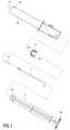
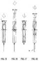
- a syringe assemblyincluding a barrel 10, a plunger 11, a hollow plunger cap 12, a hypodermic needle 13, and a needle holder 14.
- the barrel 10is a hollow cylinder which terminates in a hollow tapered nozzle 15 at a distal end thereof.
- a tapered or conical wall portion 23leads to the nozzle 15. Otherwise the barrel 10 has constant inner and outer diameters through a proximal end portion 16 thereof.
- the interior of the nozzle 15communicates with the hollow interior of the barrel 10.
- An outwardly extending flange 17 nearer the proximal end of the barrel 10facilitates gripping of the barrel with the user's fingers when it is desired to move the plunger 11 relative to the barrel 10.
- a portion of the outer surface of the barrel on the distal side of the flange 17may be serrated to facilitate gripping of the barrel during relative rotation of the barrel ad plunger, as decribed below.
- the proximal end of the barrel 10is open.
- the proximal end portion 16 of the barrel 10has a spiral slot 19 through its wall. As will be described below, this spiral slot 19 provides a retraction track for the needle holder 14 and the hypodermic needle 13.
- the spiral slot 19extends along a sufficient length to accommodate retraction of the needle holder 14 through a distance that is sufficient to draw the entire length of the needle 13 inside the barrel 10, as described in more detail below.
- the spiral slot 19extends less than 360° about the circumference of the barrel 10. In the illustrative embodiment, the spiral slot 19 extends approximately 270° about the circumference of the barrel 10. The extent of the slot 19 could be less than 270° without departing from the invention.
- the outer surface of the barrel 10preferably contains graduations (not shown) indicating the volume level of fluid in the barrel. These graduations take into account the volume of the internal components such as the needle holder 14.
- the proximal end of the plunger 11forms a knob 20 that can be grasped by a user to effect linear or rotary movement of the plunger 11 relative to the barrel 10.
- the periphery of the knob 20is serrated to facilitate gripping of the knob for rotary movement of the plunger.
- the distal end of the plunger 11forms a head 21 to accommodate the hollow rubber plunger cap 12.
- the outside diameter of the resilient cap 12is reduced in the central portion so that the cap engages the inside wall of the barrel 10 only at the pliable margins of the ends of the cap.
- the diameter of the engaging end portions of the cap 12is slightly larger than the inside diameter of the barrel 10 so that the cap presses firmly against the inside wall of the barrel to form an air-tight and liquid-tight seal at the cap/barrel interface.
- the inner margins of the cap 12make a similar tight contact with the outer surface of the needle holder 14.
- the inner margin of the cap 12may be provided with a slit valve 12a (see FIGS. 6, 7 and 8) for this purpose, i.e., to seal against the outer surface of the needle 13 when it extends therethrough.
- the distal end 22 of the cap 12is conical to conform to the conical distal end 23 of the inside surface of the barrel 10 when the plunger 11 is fully advanced within the barrel.
- the head 21 of the plunger 11is configured to fit tightly within the hollow plunger cap 12. With the cap 12 locked onto the head 21 of the plunger, the flat proximal end 24 of the cap abuts the flat surface of a circular disc 25 at the base of the plunger head 21. Due to the air-tight and liquid-tight seal between the plunger cap 12 and the barrel 10, as well as the needle holder 14, advancing movement of the plunger 11 inside the barrel 10 creates pressure in the interior of the barrel between the plunger cap and the distal end of the barrel. Similarly, retracting movement of the plunger 11 creates a partial vacuum in that portion of the barrel interior. Alternatively, a resilient barrel contacting with the rigid plunger plate 25 modified to carry a central elastic O ring can be used.
- the hypodermic needle 13is mounted on the distal end of the elongated needle holder 14, which is detachably interlocked to the barrel 10. Prior to use of the syringe assembly, the needle 13 is covered by a protective cap (not shown) which prevents needle pricks and preserves sterility prior to use. Both the needle 13 and the distal portion of the needle holder 14 are hollow, and the interior of the hollow needle 13 communicates with the interior of the hollow distal portion of the needle holder 14. The needle holder 14 further communicates with the interior of the barrel 10 through an aperture 26 in the side wall of the hollow portion of the needle holder 14 (FIGS. 2 and 3).
- the aperture 26Prior to and during use of the syringe assembly for injection of medicine or withdrawal of blood (hereafter referred to as "normal use"), the aperture 26 is positioned at the base of the barrel nozzle 15. The aperture 26 permits blood or medicine to enter or exit from the barrel 10 via the needle holder 14 and the needle 13. This arrangement minimizes the dead space within which liquid can be retained in the syringe.
- the needle holder 14is locked to the barrel 10, and the plunger 11 and its cap 12 are free to slide longitudinally back and forth along the needle holder.
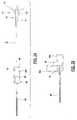
- the needle holder 14comprises an L-shaped rod having a longitudinal body portion 31 extending axially and including the aperture 26, and a lateral arm 32 extending radially across the barrel 10 at the proximal end of the rod.
- the needle holderis mounted in a longitudinal channel 33 formed as an integral part of the plunger 11.
- Multiple spaced apart resilient detents or retaining elements 34project inwardly from the opposed walls of the channel 33 to hold the needle holder 14 within the channel.
- These detents or retaining elements 34are deflected during insertion of the needle holder 14 into the channel 33, and then the elements 34 spring back to their original positions after the needle holder is in place.
- the ribs 60 and 62 that form the opposed walls of the channel 33extend all the way to the inside wall of the barrel 10 (see FIG.
- a locking detent 75(described below) locks the arm and plunger together to prevent relative longitudinal movement after retraction is complete.
- the outer surface of the distal end portion of needle holder 14is seemlessly molded with a special texture to form a tapered surface 14a which mates with a complementary tapered surface 15a on the inside wall of the barrel nozzle 15.
- These tapered surfaces 14a and 15aare conventionally known as locking luer tapers, and the angle of the taper (typically expressed as a percentage of the diameter) is conventionally known as a locking taper angle. In a preferred embodiment, a 6% taper angle is used.
- the locking surfaces 15a and 14aare engaged during assembly of the needle syringe, when the plunger 11 and needle holder 14 are inserted into the barrel 10 through the open proximal end of the barrel.
- the resultant locking luer tapercan be released only by the application of simultaneous axial and rotational forces.
- the proximal end of the needle holder 14is also locked to the barrel 10, via the lateral arm 32.
- This arm 32extends radially beyond the plunger and fits into the spiral slot 19.
- the arm 32can be locked to the barrel 10 at the distal end of the spiral slot 19 and, when so locked, permits only reciprocal linear movement of the plunger 11, to create vacuum to withdraw medication or blood and pressure to deliver medication to the patient via the hypodermic needle.
- the plunger 11cannot be rotated within the barrel 10.
- the armis locked in the detent 75 at the proximal end of the slot, it disables the entire syringe.
- a mechanical latch 50is manually actuated to unlock the arm 32 and thereby permit rotation of the plunger 11 relative to the barrel 10 along the spiral track 19. This relative rotation retracts and locks the needle-needle holder assembly within the barrel-plunger assembly.
- the plunger 11can be in any desired position, e.g., to permit blood or medication to be retained in the syringe.
- the preferred latch mechanism 50 of FIGS. 1 and 10-14includes a longitudinally grooved tab 51 mounted for sliding movement upon a short longitudinal track 52 on the outer wall of the barrel 10.
- the groove 53 of the tab 51is shaped to match the outer surface of the track 52 so that the tab 51 slides back and forth on the track 52.
- the outer surface 54 of the tab 51is serrated to facilitate movement thereof with the user's finger or thumb.
- the locking tab 51also includes a small recess 56 formed within the groove 53.
- This recess 56is sized and located to engage a terminal end part of the lateral arm 32 of the needle holder 14, when the lateral arm 32 is at a distal end portion of the spiral slot 19 with the needle 13 in a fully extended position. This prevents the tab from sliding in the proximal direction along the track 52. This engagement can be overcome by a deliberate manually applied force to retract the tab 51 when it is desired to retract the needle.
- the latch 50can be opened or closed by linear movement of the locking tab 51 along the track 52.
- the needle holder arm 32is positioned at the distal end of the spiral slot 19, which is immediately adjacent the flange 17, and the locking tab 51 is advanced on the track 52 to retain the arm 32 at the distal end of the slot 19.
- the locking tab 51retains the arm 32, the needle holder 14 cannot rotate and thus cannot travel along the spiral slot 19 for retraction of the hypodermic needle 13.
- a hinged locking tab 59(FIGS. 21-23) connected by a living hinge 61 to the barrel 10 may be provided.
- the tab 59has a through aperture 63 for engaging the lateral arm 32 at the distal end of the slot 19.
- Detents 65 on the outer wall of the barrel 10may hold the tab in place when engaged with the lateral arm 32 of the needle holder 14.
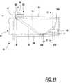
- a proximal end of the spiral slot 19includes a keyhole-shape locking feature 19a (FIG. 11) to lock the end of the arm 32 in place when the needle holder has been fully retracted.
- FIG. 11Also illustrated in FIG. 11 are the approximate positions of the lateral arm 32 of the needle holder 14 as it is rotated through 90°, 180° and 270° relative to the spiral slot 19. The needle holder 14 ascending proximally on the spiral 19 slot passes into the keyhole 19a and through the angular detent 75, snapping into the locked position with a click.
- the plunger 11will be seen to have a plurality of ribs which extend radially outwardly at substantially 90° intervals.
- a first pair of these ribs 60, 62define the longitudinal channel 33 for holding the needle holder 14 as described above.
- a single rib 64projects diametrically oppositely of these ribs 60 and 62.
- a further pair of diametrically oppositely extending ribs 66 and 68are formed in a plane at right angles to the ribs 60, 62 and 64.
- these latter ribs 66 and 68include recessed surfaces 70, 72 toward their proximal ends.
- a transverse rectangular slot 110 in the plunger 11forms an access slot for a mold insert to form the detent 75, and a hole 120 (FIG. 5) in the plunger head 20 provides access for a tool used to push the needle holder 14 longitudinally into the barrel 10 during initial assembly of the syringe (after the needle holder has been snappingly engaged beneath the detents 34 of the channel 33).
- the recessed surfaces 70 and 72 of the ribs 66 and 68provide a relief space for a proximal end part of the barrel 10 when the open end of the barrel 10 is pressed together, for example by applying pressure between a thumb and a finger. As best viewed in FIG. 20, this action momentarily distorts the proximal open end of the barrel 10 to a somewhat elliptical shape so as to permit the initial insertion of the lateral arm portion 32 of the needle holder 14 past the proximal open end of the barrel 10 and into the spiral slot 19.
- An indexing recess 76(FIG.
- a shallow channel 77(FIG. 11) in the end of the barrel 10 holds the needle holder 14 in the correct angular position during assembly, and a shallow channel 77 (FIG. 11) further facilitates insertion of the needle holder 14 into the barrel 10 while the barrel is temporarily distorted to its elliptical shape.
- the pressure on the barrel 10is released, it resumes its generally circular cross-sectional shape for retaining the lateral arm 32 in engagement with the spiral slot 19.
- the plungerwhen the tab 51 is retracted to unlock the arm 32, the plunger can be in any desired longitudinal position. That is, the plunger can be fully advanced, fully retracted, or at any intermediate position. This is advantageous because it might be desired to retract the needle after only a portion of a dose of medication has been injected into the patient, or it might be desired to retain a portion of a blood sample withdrawn from a patient within the syringe.
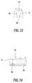
- a latex seal(not shown) may be provided at the end of the nozzle 15, or a needle cap 78 (FIG. 18) may be utilized.
- the plunger 11includes an integral circular retaining plate 55.
- the diameter of this plate 55matches the inside diameter of the guide barrel 10 so that it tends to maintain the desired circular shape of the inside wall of the barrel 10. Stresses exerted on the wall of the barrel during use can tend to distort its desired circular configuration, and if the distortion becomes large enough, the arm 32 can escape from the spiral slot 19. With the retainer plate 55 riding on the inside wall of the barrel 10, however, such excessive distortion is prevented, and thus retention of the arm 32 within the spiral slot 19 is ensured.
- the longitudinal ribs of the plungeralso glide on the inside wall of the barrel 10 at approximately 90° intervals from each other, and thus further ensure that the barrel retains its desired circular configuration.
- a number of other features of the design of the barrel 10help to retain the shape of the barrel 10, particularly in the region of the spiral slot 19, so as to further assist in retaining the arm 32 within the spiral slot 19.
- One of these featuresis the design of the spiral slot 19 itself, which, as mentioned above, extends less than 360° around the circumference of the barrel.
- the spiral slotextends only around approximately 270° of the circumference of the barrel 10. The extent of the slot could be even less than 270° without departing from the invention.
- the track 52 and a diametrically opposed similarly raised rib 58are integrally formed in the side wall of the proximal end portion of the barrel 10 preferably running longitudinally from its proximal end to the flange 17.
- These raised ribs 52, 58further assure the structural integrity and rigidity of this portion of the barrel 10. Additional reinforcement may be provided by increasing the thickness of the barrel wall in this proximal region, or by the use of a different material in the segment of the barrel containing the spiral slot.
- a through slot 57is provided at a suitable point in the rib 58 to permit the end part of the arm 32 to pass thereby as it slides along this portion of the spiral slot 19.
- the barrel 10 and the needle holder 14are held stationary, and the plunger 11 is free to move longitudinally relative to both the barrel 10 and the needle holder 14.
- Advancing movement of the plunger 11is limited by contact of the plunger cap 12 with the end wall of the barrel 10, as shown in FIG. 9.
- Retracting movement of the plunger 11is limited by contact of the plunger disc 25 with the arm 32.
- an internal ring 79(FIG. 11) may be provided on the inside surface of the barrel to engage the disc 25 on the distal side of the spiral slot 19, to prevent further retraction of the plunger and protect against the leakage of fluids through the spiral slot 19 in the barrel wall.
- the needle holder 14is locked to the barrel 10 by virtue of the taper lock between the distal portion of the needle holder and the barrel nozzle 15, and the forced or strained locking engagement of the lateral arm 32 by the tab 51.
- the needle holdercan be locked to the nozzle by a threaded connection, as described in more detail in my prior U.S. Patent No. 5,643,222.
- the plunger 11is also free to move longitudinally relative to the needle holder 14 because the needle holder is not locked to the plunger in that direction.
- the locking of the lateral arm 32 by the tab 51prevents rotational movement of the plunger as well as the needle holder, and also prevents the plunger from being accidentally pulled out. As long as the lateral arm 32 of the needle holder is locked by the tab 51, the syringe assembly is in its normal operating mode.
- the needle 13can be retracted into the plunger 11 and the barrel 10. This requires axial movement of the needle holder 14 within the barrel 10 toward the proximal end thereof, which in turn requires that the needle holder 14 be unlocked for movement along the spiral slot 19.
- the arm 32is unlocked by retracting the tab 51.
- the plunger knob 20is turned to rotate the plunger 11 clockwise (as viewed from the proximal end) relative to the barrel.
- the needle holder 14rotates in unison with the plunger because the arm 32 is captured between the opposed parallel walls of the channel 33 in which the needle holder is mounted in the plunger.
- Rotation of the needle holder 14 relative to the barrel(1) retracts the needle holder within the plunger by the camming action of the wall of the spiral slot 19 acting on the arm 32, and (2) releases the locking luer taper at the distal end of the barrel nozzle 15 due to the resulting compound rotational and longitudinal forces applied to the tapered surfaces 15a and 14a.
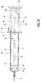
- the arm 32traverses the entire length of the spiral slot 19, thereby retracting the entire needle holder 14 through a corresponding axial distance within the plunger 11 (see FIG. 17).
- the needle 13is retracted along with the needle holder 14, and thus the needle is retracted completely within the barrel nozzle 10 and the plunger 11, as illustrated in FIG. 17.
- the spiral slot 19is formed in a proximal end Portion of the barrel 10.
- the spiral slotpreferably has a constant rate of curvature along its length and as noted above preferably extends only (approximately) 270° or less about the circumference of the barrel 10.
- the illustrative syringeneed not be any longer than a conventional syringe because conventional syringes are made longer than required to provide more than the desired fluid volume, so as to avoid inadvertent withdrawal of the plunger and the resultant spillage of the syringe contents.
- the extra barrel lengthalso accommodates the spiral slot 19 in the space between the plunger knob and the finger flanges.
- the present inventionpermits the extension of the barrel length in this area to be used for the needle-retracting mechanism.
- the end of the arm 32physically bends the detent 75 and snaps into the keyhole-shaped detent notch 19a (FIGS. 1, 10 and 11) formed by the walls of the slot so that the user feels a click at the end of the needle retraction.
- the locking actionis automatic. Then if the user attempts to turn the plunger knob 20 in the opposite direction, such attempt is met with firm resistance. This is a safety feature to prevent the needle from being returned beyond the end of the barrel nozzle, and to discourage re-use of the syringe.
- a proximally inwardly divergent locking detent 75(FIG. 4) is formed projecting from the inside wall of the channel 33 near the proximal end thereof to prevent the plunger 11 from being withdrawn from the barrel 10 after the needle holder 14 has been retracted.
- the arm 32deflects the detent 75 as the arm is retracted past the detent, but the arm 32 then engages the proximal end of the detent so as to block any effort to retract the plunger 11 over the needle holder 14.
- This locking of the arm 32 by detent 75also prevents further rotation of the plunger.
- the plunger knob 20also blocks movement of the arm 32, and hence of the needle holder 13 and needle 14, back in the proximal direction.
- the protective cap 78(FIG. 18) is removed from the needle 13, and the required amount of medication is aspirated into the barrel 10.
- the injection site on the body of a patientis determined and the skin is cleaned with an antiseptic solution.
- location of the needle tip in the veinis confirmed by aspirating a small amount of blood into the transparent barrel 10.
- the plunger 11is then advanced to force the medication from the barrel 10 into the vein.
- the needle 13is withdrawn from the patient, the tab 51 is retracted to release the arm 32, and the plunger knob 20 is rotated clockwise until the user feels the arm 32 snap into the detent notch 19a at the proximal end of the spiral slot 19.
- the spiral slot 19may alternatively be configured to require counterclockwise, instead of clockwise, rotation of the plunger knob 20.
- the syringe assemblyperforms all the conventional functions of injection syringes and yet, upon completion of injection, the hypodermic needle 13 is concealed within the barrel 10.
- the syringe assemblycan receive and disperse medications any number of times for a given patient by reciprocal longitudinal movement of the plunger 11 within the barrel 10.
- Another advantage of the syringe assemblyis that its design prevents the plunger 11 from slipping out of the barrel 10 during normal use of the assembly.
- the syringe assembly of this inventionis easy to manufacture, cost-effective, and easy to use in the field.
- the partscan all be made by conventional plastic molding and using readily available metal needle stock.
- the plastic partscan be made by injection moving medical grade polymers such as polypropylene.
- the plunger seal or capcan be molded from natural or synthetic elastomeric polymers.
- the spiral channel within the wall of the barrelis molded by slides having spiral elevations contacting the core pin. The mold is not opened until the barrel is stripped off the core pin to preserve the integrity of the molded spiral track.
- the detents within the plunger channel 33are molded by pins projecting inside the core of the plunger channel.
- the final assemblyis compact because the needle holder 14 is retracted directly into the plunger 11 itself, and thus the plunger 11 need not be fully withdrawn for needle retraction to occur.
- the syringe assemblycontributes minimally to the bulk of refuse. Since retraction of the needle 13 is effected, by turning the plunger knob 20 at the proximal end of the assembly, the hand of a user does not come into the vicinity of the needle point, thereby minimizing the possibility of a needle prick during retraction.
- the assemblyemploys substantially the same number of components as conventional syringes, and does not require additional guards, sheaths, sleeves, springs, etc. to conceal the needle following use.
- FIG. 24depicts an over-the-needle (“OTN") catheter assembly including an OTN catheter 80 and the syringe assembly of FIGS. 1-20 (only a distal end portion of which is illustrated) with a hypodermic needle 13 mounted therein.
- the OTN catheter 80is a polymeric catheter having an elongated tip 82 mounted thereto.
- a proximal end surface 84 of the OTN catheter 80is coaxially mounted over the nozzle 15 and the hypodermic needle 13 protrudes through both the nozzle 15 and the OTN catheter 80.
- the elongated tip 82 of the catheter 80is advanced over the needle 13.
- the needle 13 and catheter tip 80Prior to use, i.e., prior to inserting the needle 13 and catheter tip 82 into a vein, the needle 13 and catheter tip 80 are enclosed by a removable cap (not shown).
- the catheter 80includes an internal valve, such as a slit valve 86 to restrict the flow of fluids therethrough.
- an internal valvesuch as a slit valve 86 to restrict the flow of fluids therethrough.
- the OTN catheter 80Prior to and during normal use of the OTN catheter assembly, the OTN catheter 80 is held engaged over the nozzle 15 of the syringe assembly by locking luer tapers on the outer surface 115 of the nozzle 15 and the inner surface 81 of the catheter 80.
- the needle carrier 14 and the mounted needle 13are retracted in the manner described above. At this retracted position the needle carrier 14 is irretrievably locked in place inside the barrel as described above.
- the syringeis then disengaged from the catheter by simultaneously rotating and withdrawing the syringe, so as to release the locking luer taper formed by surfaces 115 and 81, as shown in FIG. 24.
- the OTN catheter 80is then advanced into the vein, and secured to the skin by adhesive tapes.
- the purpose of the locking luer taper formed by surfaces 115 and 81is to mechanically unify the syringe with the OTN catheter so that insertion force applied to the syringe is directly transmitted to the hypodermic needle 13 and catheter 80. Release of the locking liner taper disassociates this mechanical unity, permitting the syringe (with the needle 13 retracted) to be moved from the catheter 80.
- confirmation that the needle 13 and catheter tip 82 are located in the veincan be made by viewing blood entering the catheter 80 by capillary action. It, however, is also possible to confirm a flashback within the syringe barrel by partially retracting the plunger 11 relative to the barrel 10 to assure that continuity between the needle 13 and the vein is established.
- the side aperture 26 of the needle holder 14opens up into the flashback chamber thus created. Confirmation of proper insertion in the vein is indicated by blood entering the barrel chamber via the side aperture 26 in the needle holder 14.
- the skin of a patientis first prepared and a peripheral vein is made prominent. Under aseptic precautions the vein is punctured with the needle 13 and catheter tip 82, and the location of the needle tip is judged by the change in color under the catheter or by the appearance of blood in the catheter or the flashback chamber. Once the location of the needle tip is confirmed, the needle carrier is retracted in the manner described above. While advancing and retaining the OTN catheter 80 in the vein, the syringe assembly is removed and an intravenous line is connected to the catheter 80. Finally, the catheter 80 is secured to the skin of the patient by adhesive tape.
- the OTN catheter 80As shown in FIG. 25, it is possible to replace the OTN catheter 80 with the slit valve 86 with an OTN catheter assembly 90 having two orthogonally disposed body portions 90a and 90b, which are operatively coupled to the elongated catheter tip 82 by a rotary-type 3-way ball valve mechanism 92.
- the elongated catheter tip 82is the same as that of the catheter 80 of FIGS. 24-26.
- the detents 34 in the plunger channel 33add precision to the needle holder movement. For example, straight axial retraction of the needle in the plunger channel 33 avoids angulation of the needle and puncture of the barrel cavity. It does not require extending the overall length of the syringe, and avoids the need for special measures such as breaking the plunger to prevent re-use.
- the spiral track 19is molded in the barrel itself and offers positive engagement of the needle holder without requiring additional arts or complexity.
- the proximal end part 16 of the barrel 10is strengthened by reducing the circumference of the spiral slot 19 from 360° to 270° or even further. Additional linear reinforcing ribs 52, 50 of material are incorporated in the barrel for strength.
- the number of the components (except for the locking tab 51) in the present inventionis the same as in a conventional syringe to keep it cost effective.
- syringeThe operation of syringe is one-way so that accidental misuse is minimized, i.e., once retracted the needle holder is locked in place, so the needle cannot be re-extended.
- Operation of the syringeis particularly safe because all the required manipulations of the various parts of the syringe are performed at or near the proximal end of the syringe, well away of the needle, during both the normal and retracting modes of operation.
- the locking and disablementis automatic when the needle holder is retracted by rotating the plunger and is positively indicated by an audible click produced by the detent 75. Pull-back of the plunger is also blocked by the detent 75 in the plunger while the back-tracking of the needle holder in the spiral slot is also blocked by both the detent 75 and the interfering contact of the plunger knob and barrel margin and keyhole detent 19a.
- the syringe with leftover medicinecan be rendered safe by rotary retraction of the needle holder, while capping of nozzle will prevent spillage.
- the syringe assembly as describedmay be used to dispense medication or as a blood collection device. It may also be used to place an over-the-needle catheter, as described above.
Landscapes
- Health & Medical Sciences (AREA)
- Engineering & Computer Science (AREA)
- Heart & Thoracic Surgery (AREA)
- Vascular Medicine (AREA)
- Anesthesiology (AREA)
- Biomedical Technology (AREA)
- Environmental & Geological Engineering (AREA)
- Hematology (AREA)
- Life Sciences & Earth Sciences (AREA)
- Animal Behavior & Ethology (AREA)
- General Health & Medical Sciences (AREA)
- Public Health (AREA)
- Veterinary Medicine (AREA)
- Infusion, Injection, And Reservoir Apparatuses (AREA)
Abstract
Description
Claims (12)
- A syringe assembly, comprising:an elongated, generally cylindrical barrel having a hollow interior forming ahollow nozzle located at a distal end of said barrel and opening into the interior of saidbarrel;a plunger slidably mounted in said barrel and forming a longitudinal cavity;a needle holder slidably mounted in said longitudinal cavity of said plunger
characterized by:means defining a spiral channel (19) on said barrel extending along aproximal end portion of said barrel for engaging said needle holder and retracting saidneedle holder within the barrel in response to relative rotational movement between thebarrel and the needle holder; andlatching means (50 or 59) on said barrel for latching and unlatching saidneedle holder at a distal end of said spiral channel. - The syringe assembly of claim 1 wherein said latching means comprises alocking element (50)slidably mounted on said barrel for reciprocating movementbetween a locking position at said distal end of said spiral channel and a non-lockingposition away from said distal end of said spiral channel.
- The syringe assembly of claim 2 wherein said latching means includesmeans defining a groove (53) on said locking element and a longitudinal track (52) on anouter surface of said barrel for engaging said groove for effecting sliding movement ofsaid blocking element.
- The syringe assembly of claim 1 wherein said barrel includes anoutwardly extending finger flange (17) to facilitate gripping of the barrel, and the distalend of said spiral channel (19) terminates at said flange (17).
- The syringe assembly of claim 1 wherein said needle holder has a lateralarm (32) which extends radially into the spiral channel (19) and wherein said latchingmeans (50 or 59) is moveable to capture the lateral arm of said needle holder in saidspiral channel at a point adjacent to said flange.
- The syringe assembly of claim 1 wherein said needle holder includes alateral arm (32) extending laterally through said plunger cavity to said spiral channel (19), and said latching means (50 or 59) is mounted for movement into and out ofregistry with a distal end of said spiral channel (19) for capturing and releasing saidlateral arm at the distal end of said spiral channel.
- The syringe assembly of claim 1 wherein said spiral channel (19) isformed in the wall of said barrel and extends radially through the wall of said barrel, andextends for no more than 270° around the barrel.
- The syringe assembly of claim 1 wherein said spiral channel (19) includesmeans (19a) at a proximal end thereof for resisting advancing movement of said needleholder after it has been fully retracted.
- The syringe assembly of claim 1 wherein said longitudinal cavity of saidplunger includes a plurality of detent means (34) for slidably retaining said needle holderwithin said longitudinal cavity.
- The syringe assembly of claim 1 and further characterized by at least onelongitudinal rib (52 or 56) formed along the proximal end portion of said barrel andextending approximately the length of said spiral channel for strengthening the proximalend portion of said barrel.
- The syringe assembly of claim 10 wherein said latching means includes alocking element (50) and wherein one of said ribs (52, 56) defines a track on which saidlocking element is slidably mounted for movement between a locking position at a distalend of a spiral channel (19) and a non-locking position away from said distal end of saidspiral channel.
- The syringe assembly of claim 1 wherein said needle holder (14) includesa lateral arm (32) for engaging the spiral channel (19) and said barrel has an open endand said plunger (11) includes recesses (70, 72) alignable with said open end of saidbarrel for defining a relief space for deformation of said open end of barrel to permitinitial insertion of said lateral arm (32) of said needle holder (14) past said open end ofsaid barrel and into said spiral slot (19).
Applications Claiming Priority (2)
| Application Number | Priority Date | Filing Date | Title |
|---|---|---|---|
| US08/972,548US6117112A (en) | 1997-11-18 | 1997-11-18 | Single-use safety syringe |
| US972548 | 1997-11-18 |
Publications (3)
| Publication Number | Publication Date |
|---|---|
| EP0916354A2true EP0916354A2 (en) | 1999-05-19 |
| EP0916354A3 EP0916354A3 (en) | 1999-08-25 |
| EP0916354B1 EP0916354B1 (en) | 2003-03-26 |
Family
ID=25519795
Family Applications (1)
| Application Number | Title | Priority Date | Filing Date |
|---|---|---|---|
| EP98120753AExpired - LifetimeEP0916354B1 (en) | 1997-11-18 | 1998-11-02 | Single-use safety syringe |
Country Status (8)
| Country | Link |
|---|---|
| US (1) | US6117112A (en) |
| EP (1) | EP0916354B1 (en) |
| JP (1) | JPH11226125A (en) |
| CN (2) | CN1183976C (en) |
| AU (1) | AU737080B2 (en) |
| CA (1) | CA2254174C (en) |
| DE (1) | DE69812542T2 (en) |
| IN (1) | IN189016B (en) |
Cited By (3)
| Publication number | Priority date | Publication date | Assignee | Title |
|---|---|---|---|---|
| EP3111982A1 (en)* | 2012-03-12 | 2017-01-04 | Becton, Dickinson and Company | Catheter adapter port valve |
| EP1877120B1 (en)* | 2005-04-13 | 2017-03-08 | Coeur, Inc. | Syringe plunger jacket with expandable seal |
| TWI675645B (en)* | 2018-03-26 | 2019-11-01 | 慈濟學校財團法人慈濟科技大學 | Rotating retractable safety needle |
Families Citing this family (48)
| Publication number | Priority date | Publication date | Assignee | Title |
|---|---|---|---|---|
| US6280401B1 (en)* | 1993-08-23 | 2001-08-28 | Sakharam D. Mahurkar | Hypodermic needle assembly |
| JP4593714B2 (en)* | 2000-02-10 | 2010-12-08 | 株式会社根本杏林堂 | Syringe outer cylinder, syringe holder, syringe piston and piston holder |
| GB0003790D0 (en) | 2000-02-18 | 2000-04-05 | Astrazeneca Uk Ltd | Medical device |
| US6530903B2 (en) | 2000-02-24 | 2003-03-11 | Xiping Wang | Safety syringe |
| US20040030294A1 (en) | 2001-11-28 | 2004-02-12 | Mahurkar Sakharam D. | Retractable needle single use safety syringe |
| USD470234S1 (en) | 2001-12-26 | 2003-02-11 | Sakharam D. Mahurkar | Safety syringe |
| USD474838S1 (en) | 2002-01-24 | 2003-05-20 | Sakharam D. Mahurkar | Safety syringe |
| US6764465B2 (en)* | 2002-06-24 | 2004-07-20 | Long Hsiung Chen | Syringe with retractable needle and safety lock |
| IL157981A (en) | 2003-09-17 | 2014-01-30 | Elcam Medical Agricultural Cooperative Ass Ltd | Auto-injector |
| DE10348603A1 (en)* | 2003-10-20 | 2005-05-19 | Klinika Medical Gmbh | Cannula holder comprises an unlocking mechanism which is constituted so that after its operation the cannula and/or the adapter will fall into the cannula container |
| US7226434B2 (en) | 2003-10-31 | 2007-06-05 | Tyco Healthcare Group Lp | Safety shield |
| US7988664B2 (en) | 2004-11-01 | 2011-08-02 | Tyco Healthcare Group Lp | Locking clip with trigger bushing |
| US7101351B2 (en) | 2003-11-03 | 2006-09-05 | Becton, Dickinson And Company | Safety device for a syringe |
| US7468054B2 (en) | 2003-11-03 | 2008-12-23 | Becton, Dickinson And Company | Safety shield system for a syringe |
| US7497847B2 (en) | 2003-11-03 | 2009-03-03 | Becton, Dickinson And Company | Safety shield system for a syringe |
| US7604613B2 (en) | 2004-01-20 | 2009-10-20 | Beckton, Dickinson And Company | Syringe having a retractable needle |
| US7344517B2 (en) | 2004-01-20 | 2008-03-18 | Becton, Dickinson And Company | Syringe having a retractable needle |
| IL160891A0 (en) | 2004-03-16 | 2004-08-31 | Auto-mix needle | |
| US7905857B2 (en) | 2005-07-11 | 2011-03-15 | Covidien Ag | Needle assembly including obturator with safety reset |
| US7828773B2 (en) | 2005-07-11 | 2010-11-09 | Covidien Ag | Safety reset key and needle assembly |
| US7850650B2 (en) | 2005-07-11 | 2010-12-14 | Covidien Ag | Needle safety shield with reset |
| US8062252B2 (en) | 2005-02-18 | 2011-11-22 | Becton, Dickinson And Company | Safety shield system for a syringe |
| US20060276747A1 (en) | 2005-06-06 | 2006-12-07 | Sherwood Services Ag | Needle assembly with removable depth stop |
| CA2550114C (en) | 2005-06-20 | 2013-11-19 | Sherwood Services, Ag | Safety shield for medical needles |
| US7731692B2 (en) | 2005-07-11 | 2010-06-08 | Covidien Ag | Device for shielding a sharp tip of a cannula and method of using the same |
| US7654735B2 (en) | 2005-11-03 | 2010-02-02 | Covidien Ag | Electronic thermometer |
| US9358348B2 (en)* | 2006-06-14 | 2016-06-07 | Covidien Lp | Safety shield for medical needles |
| MX2010001974A (en)* | 2007-08-20 | 2010-08-18 | Global Medisafe Holdings Ltd | Safety syringe with plunger locking means. |
| WO2009042874A1 (en) | 2007-09-27 | 2009-04-02 | Tyco Healthcare Group Lp | I.v. catheter assembly and needle safety device |
| US8357104B2 (en) | 2007-11-01 | 2013-01-22 | Coviden Lp | Active stylet safety shield |
| DE602008002806D1 (en) | 2007-12-20 | 2010-11-11 | Tyco Healthcare | Locking cap arrangement with spring-loaded collar |
| NL2001702C2 (en)* | 2008-06-19 | 2009-12-22 | Addino B V | Injection syringe with possibility of needle storage. |
| WO2009158648A1 (en)* | 2008-06-26 | 2009-12-30 | Becton, Dickinson And Company | Passive reuse prevention syringe that uses a retaining ring lock |
| ES2766253T3 (en) | 2008-09-18 | 2020-06-12 | Becton Dickinson Co | Medical Plunger Injector with Ratchet Function |
| US8864725B2 (en) | 2009-03-17 | 2014-10-21 | Baxter Corporation Englewood | Hazardous drug handling system, apparatus and method |
| WO2010126536A1 (en)* | 2009-04-27 | 2010-11-04 | Becton, Dickinson And Company | Passive refuse prevention syringe that uses a tip lock |
| US7918821B2 (en) | 2009-05-05 | 2011-04-05 | Mahurkar Sakharam D | Universal safety syringe |
| US8066668B2 (en)* | 2009-06-26 | 2011-11-29 | Becton, Dickinson And Company | Passive reuse prevention syringe that uses a flange lock |
| JP4981949B2 (en)* | 2010-05-07 | 2012-07-25 | 株式会社根本杏林堂 | Chemical solution injection system with buttock-enhanced syringe and automatic injection device |
| CN105498049B (en)* | 2011-03-17 | 2018-09-21 | 贝克顿·迪金森公司 | Medical injector with ratchet-type plunger |
| CA2854003C (en) | 2011-11-07 | 2020-07-14 | Safety Syringes, Inc. | Contact trigger release needle guard |
| US10426932B2 (en)* | 2013-01-17 | 2019-10-01 | Toby Wexler | Method and apparatus for introducing an intravenous catheter |
| CN104721912B (en)* | 2015-03-26 | 2018-04-27 | 江苏阳普医疗科技有限公司 | A kind of disposable anti-blood vessel punch through style intravenous infusion needle |
| CN109498910B (en)* | 2019-01-15 | 2021-03-19 | 南昌爱美美容医院有限公司 | A medical syringe for preventing airflow pollution during use |
| CN114593244A (en)* | 2019-03-26 | 2022-06-07 | 太平洋工业株式会社 | valve |
| WO2020237420A1 (en)* | 2019-05-24 | 2020-12-03 | Becton, Dickinson And Company | Needle-tract assistant including components and methods thereof |
| EP3821925B1 (en) | 2019-09-18 | 2024-03-20 | KAISHA PACKAGING Private Ltd. | Device for locking a plunger rod of a syringe after use and preventing re-use of the syringe, and syringe assembly |
| USD948714S1 (en) | 2020-06-22 | 2022-04-12 | KAISHA PACKAGING Private Ltd. | Syringe plunger lock |
Family Cites Families (207)
| Publication number | Priority date | Publication date | Assignee | Title |
|---|---|---|---|---|
| BE541390A (en)* | 1955-10-18 | |||
| US2925083A (en)* | 1957-12-27 | 1960-02-16 | Clarence D Craig | Hypodermic syringe with hood for guarding and concealing the needle |
| US3610240A (en)* | 1967-06-13 | 1971-10-05 | American Hospital Supply Corp | Intravenous catheter apparatus with catheter telescoped inside puncturing cannula |
| DE1914749A1 (en) | 1968-03-26 | 1969-10-09 | Matburn Holdings Ltd | Transfusion device, especially intravenous catheter |
| US3658061A (en)* | 1970-11-10 | 1972-04-25 | Baxter Laboratories Inc | Needle guard |
| DE2415196A1 (en) | 1974-03-29 | 1975-10-16 | Hans Dr Zeidler | Intromission device for flexible insert into bodily cavities - has syringe type applicator containing viscous fluid |
| DE2507119A1 (en) | 1975-02-19 | 1976-09-02 | Kurt Dr Med Sokol | Sterile storage of vein catheter - incylinder of hypodermic syringe with cap closing tapping needle cone |
| US4068659A (en)* | 1976-07-12 | 1978-01-17 | Deseret Pharmaceutical Co., Inc. | Catheter placement assembly |
| GB2012919B (en)* | 1977-11-24 | 1982-05-19 | Wolf Gmbh Richard | Trocar sleeves |
| US4261357A (en)* | 1979-01-29 | 1981-04-14 | Critikon, Inc. | Catheter assembly for intermittent intravenous medicament delivery |
| US4245635A (en)* | 1979-01-29 | 1981-01-20 | Jelco Laboratories | Catheter assembly for intermittent intravenous use |
| US4274408A (en)* | 1979-03-26 | 1981-06-23 | Beatrice Nimrod | Method for guide-wire placement and novel syringe therefor |
| DE3042229C2 (en) | 1980-11-08 | 1983-10-27 | B. Braun Melsungen Ag, 3508 Melsungen | Insertion device for inserting elongated objects into blood vessels |
| US4424833A (en)* | 1981-10-02 | 1984-01-10 | C. R. Bard, Inc. | Self sealing gasket assembly |
| US4417886A (en)* | 1981-11-05 | 1983-11-29 | Arrow International, Inc. | Catheter introduction set |
| US4468224A (en)* | 1982-01-28 | 1984-08-28 | Advanced Cardiovascular Systems, Inc. | System and method for catheter placement in blood vessels of a human patient |
| US4425120A (en)* | 1982-04-15 | 1984-01-10 | Sampson Norma A | Shielded hypodermic syringe |
| US4529399A (en)* | 1983-05-03 | 1985-07-16 | Catheter Technology Corporation | Method and apparatus for placing a catheter |
| US4958622A (en)* | 1983-05-11 | 1990-09-25 | Selenke William M | Hypodermic syringe for taking and transporting a specimen |
| US4892525A (en)* | 1984-01-18 | 1990-01-09 | Synertex | Hypodermic needle protective barrel and cap packaging |
| US4732162A (en)* | 1985-10-18 | 1988-03-22 | Martell Medical Products, Inc. | Automatic and position-sensitive syringe and method for nonaspirating or aspirating obtaining of blood samples |
| US4826488A (en)* | 1985-11-08 | 1989-05-02 | Nelson Robert A | Hypodermic syringe needle guard |
| US4735617A (en)* | 1985-11-08 | 1988-04-05 | Nelson Robert A | Hypodermic syringe needle guard |
| US4659330A (en)* | 1985-11-08 | 1987-04-21 | Robert Nelson | Hypodermic syringe needle guard |
| US4631057A (en)* | 1985-12-17 | 1986-12-23 | Dolores A. Smith | Shielded needle |
| US4664654A (en)* | 1986-03-07 | 1987-05-12 | Strauss Eric C | Automatic protracting and locking hypodermic needle guard |
| US4931048A (en)* | 1986-04-07 | 1990-06-05 | Icu Medical, Inc. | Medical device |
| US4778453A (en)* | 1986-04-07 | 1988-10-18 | Icu Medical, Inc. | Medical device |
| USD298352S (en) | 1986-04-28 | 1988-11-01 | Burron Medical Inc. | Hypodermic needle guard |
| US4666435A (en)* | 1986-05-22 | 1987-05-19 | Braginetz Paul A | Shielded medical syringe |
| US4702738A (en)* | 1986-05-22 | 1987-10-27 | Spencer Treesa A | Disposable hypodermic syringe and needle combination having retractable, accident preventing sheath |
| US4801295A (en)* | 1986-05-22 | 1989-01-31 | Spencer Treesa A | Disposable hypodermic syringe and needle combination having retractable, accident preventing sheath |
| US4767412A (en)* | 1986-06-10 | 1988-08-30 | Seldoren Limited | Finger guards |
| US4731059A (en) | 1986-10-14 | 1988-03-15 | Medical Safety Products, Inc. | Combination needle shield/needle guard device positively locked onto detachable needle assemblies for an evacuated blood collection system and a hypodermic syringe |
| US4693708A (en)* | 1986-10-16 | 1987-09-15 | Wanderer Alan A | Combination needle shield/needle guard device for a hypodermic syringe with a permanently attached needle |
| US4846811A (en)* | 1987-01-29 | 1989-07-11 | International Medical Innovators, Inc. | Sliding sheath for medical needles |
| US4710170A (en)* | 1987-02-12 | 1987-12-01 | Habley Medical Technology Corporation | Anti-needle strike and anti-drug abuse syringe |
| US4747835A (en)* | 1987-02-19 | 1988-05-31 | Jeffrey Sandhaus | Safety device for hypodermic needles |
| US4762516A (en)* | 1987-03-05 | 1988-08-09 | Luther Medical Products, Inc. | Assembly of needle catheter protector |
| US4832696A (en)* | 1987-03-05 | 1989-05-23 | Luther Medical Products, Inc. | Assembly of needle and protector |
| US4828548A (en)* | 1987-03-16 | 1989-05-09 | Walter Gregory W | Safety catheter |
| CA1285441C (en) | 1987-03-17 | 1991-07-02 | Roy D. Mcnaughton | Mcnaughton syringe shield type b |
| US4782841A (en)* | 1987-04-07 | 1988-11-08 | Icu Medical, Inc. | Medical device |
| US4816024A (en)* | 1987-04-13 | 1989-03-28 | Icu Medical, Inc. | Medical device |
| US4767413A (en)* | 1987-04-20 | 1988-08-30 | Habley Medical Technology Corporation | Dental syringe having an automatically retractable needle |
| JP2646126B2 (en) | 1987-04-22 | 1997-08-25 | マックスウエル エドモンド ウィッソン | Parenteral device |
| US4747831A (en)* | 1987-04-29 | 1988-05-31 | Phase Medical, Inc. | Cannula insertion set with safety retracting needle |
| US4731068A (en)* | 1987-05-01 | 1988-03-15 | Hesse John E | Non-reloadable syringe |
| US4742910A (en)* | 1987-06-22 | 1988-05-10 | Staebler Charles R | Needle sheath holder |
| US4874384A (en)* | 1987-07-13 | 1989-10-17 | International Medical Innovators, Inc. | Needle safety guard |
| US4747836A (en)* | 1987-07-17 | 1988-05-31 | Luther Medical Products, Inc. | Needle guard, and assembly |
| US4838871A (en)* | 1987-07-17 | 1989-06-13 | Luther Ronald B | Needle guard, and assembly |
| US4735618A (en)* | 1987-07-20 | 1988-04-05 | Henry E. Szachowicz, Jr. | Protective enclosure for hypodermic syringe |
| US4826491A (en)* | 1987-07-27 | 1989-05-02 | Schramm James J | Needle bearing medical device with three-position shield |
| US4752290A (en)* | 1987-07-27 | 1988-06-21 | Schramm James J | Needle bearing medical device with three-position shield |
| US4850961A (en)* | 1987-07-30 | 1989-07-25 | Wanderer Alan A | Indwelling placement device with guard |
| US5002536A (en) | 1987-08-17 | 1991-03-26 | Thompson John P | Guarded needle cover |
| US4746017A (en)* | 1987-08-18 | 1988-05-24 | Bristol-Myers Company | Safety container for glass vials |
| US4928824A (en)* | 1987-09-15 | 1990-05-29 | Barasch Stephen T | Hypodermic needle sheath protection shield apparatus |
| US4813938A (en)* | 1987-09-17 | 1989-03-21 | Raulerson J Daniel | Catheter introduction syringe |
| US4819659A (en)* | 1987-09-21 | 1989-04-11 | Icu Medical, Inc. | Blood withdrawal device with movable needle guard member |
| US4834717A (en)* | 1987-09-25 | 1989-05-30 | Habley Medical Technology Corporation | Disposable, pre-sterilizable syringe for a pre-filled medication cartridge |
| US4799926A (en)* | 1987-10-13 | 1989-01-24 | Habley Medical Technology Corporation | Syringe, having self-contained, sterile, medication applying swab |
| US4950252A (en)* | 1987-11-02 | 1990-08-21 | Luther Medical Products, Inc. | Single hand actuated locking safety catheter and method of use |
| US4863436A (en)* | 1987-11-03 | 1989-09-05 | Iatroban, Ltd. | Hypodermic needle with protective cover |
| US4813426A (en)* | 1987-11-09 | 1989-03-21 | Habley Medical Technology Corporation | Shielded safety syringe having a retractable needle |
| US4790822A (en)* | 1987-12-11 | 1988-12-13 | Haining Michael L | Retractable hypodermic safety syringe |
| US4887998A (en)* | 1987-12-14 | 1989-12-19 | Martin Catherine L | Hypodermic needle guard |
| US4808169A (en)* | 1988-01-14 | 1989-02-28 | Habley Medical Technology Corporation | Disposable safety syringe having means for retracting its needle cannula into its medication cartridge |
| US4826489A (en)* | 1988-01-14 | 1989-05-02 | Habley Medical Technology Corporation | Disposable safety syringe having means for retracting its needle cannula into its medication cartridge |
| US4842591A (en)* | 1988-01-21 | 1989-06-27 | Luther Ronald B | Connector with one-way septum valve, and assembly |
| US5171300A (en) | 1988-02-01 | 1992-12-15 | Medtech Group, Inc. | Disposable hypodermic syringe |
| US4986813A (en)* | 1988-02-01 | 1991-01-22 | The MadTech Group, Inc. | Disposable hypodermic syringe |
| US5019045A (en) | 1988-03-28 | 1991-05-28 | Lee Sang D | Hypodermic syringe with a locking needle assembly and syringe combination |
| US4915697A (en)* | 1988-03-16 | 1990-04-10 | Dupont Frank | Hypodermic needle assembly |
| NZ228388A (en) | 1988-03-22 | 1992-07-28 | Davsa Seventy Fifth Pty Ltd | Syringe with needle retractor |
| US5037400A (en) | 1988-03-30 | 1991-08-06 | Oakleaf Enterprises, Inc. | Apparatus for resheathing hypodermic needles |
| US4883469A (en)* | 1988-04-08 | 1989-11-28 | Glazier Stephen C | Guard assembly for hypodermic needle |
| US4850976A (en)* | 1988-04-08 | 1989-07-25 | The Cloverline, Inc. | Combination sheath and foldable shield for hypodermic syringe needle |
| DE8804656U1 (en) | 1988-04-08 | 1988-08-04 | Bader, Mohandes, 2350 Neumünster | Medical syringe |
| US4919656A (en)* | 1988-04-11 | 1990-04-24 | Biosurge, Inc. | Safety device for hypodermic syringe to prevent stick injuries |
| US4931040A (en)* | 1988-04-13 | 1990-06-05 | Habley Medical Technology | Safety syringe having a combination needle cannula and articulating hub for retracting said cannula into a medication carpule |
| GB2217991A (en)* | 1988-05-03 | 1989-11-08 | John Cole | Needle protection |
| US4897083A (en)* | 1988-05-09 | 1990-01-30 | Martell Michael D | Syringe needle guard |
| US5195992A (en) | 1988-05-13 | 1993-03-23 | Baxter International Inc. | Protector shield for needles |
| US4860742A (en)* | 1988-05-16 | 1989-08-29 | Medical Innovations Corporation | Assembly of wire inserter and lock for a medical wire |
| US4932940A (en)* | 1988-06-06 | 1990-06-12 | Walker Cedric F | Needle guard device |
| US5015241A (en) | 1988-06-20 | 1991-05-14 | Feimer Michael P | Safety system for hypodermic syringe and needle |
| US4915696A (en)* | 1988-06-20 | 1990-04-10 | Feimer Michael P | Safety system for hypodermic syringe and needle |
| US4909794A (en)* | 1988-06-24 | 1990-03-20 | Habley Medical Technology Corporation | Combination retractable needle cannula and cannula lock for a medication carpule |
| US5088988A (en) | 1988-06-28 | 1992-02-18 | Sherwood Medical Company | Combined dental syringe and needle shield |
| US5127910A (en) | 1988-06-28 | 1992-07-07 | Sherwood Medical Company | Combined syringe and needle shield and method of manufacture |
| US5147326A (en) | 1988-06-28 | 1992-09-15 | Sherwood Medical Company | Combined syringe and needle shield and method of manufacture |
| US5160326A (en) | 1988-06-28 | 1992-11-03 | Sherwood Medical Company | Combined syringe and needle shield |
| US5217437A (en) | 1988-06-28 | 1993-06-08 | Sherwood Medical Company | Needle protecting device |
| US5067944A (en) | 1988-07-05 | 1991-11-26 | Jerry Robles | Hypodermic needle guard |
| US4927417A (en)* | 1988-07-07 | 1990-05-22 | Schneider Medical Technologies, Inc. | Safety sleeve adapter |
| US5088987A (en) | 1988-07-19 | 1992-02-18 | Noonan Jr Thomas J | Syringe |
| US4828107A (en)* | 1988-07-25 | 1989-05-09 | Treesa Spencer | Disposable container for syringes |
| US4932946A (en)* | 1988-07-29 | 1990-06-12 | Shields Jack W | Hub-mounted, slit-elastic needle guard |
| US4929241A (en)* | 1988-08-05 | 1990-05-29 | Kulli John C | Medical needle puncture guard |
| US4906235A (en)* | 1988-08-22 | 1990-03-06 | Roberts Christopher W | Needle guard |
| US5057088A (en) | 1988-08-23 | 1991-10-15 | Krishna Narayanan | Needle guard |
| NL8802106A (en) | 1988-08-26 | 1990-03-16 | Abraham Van Den Haak | NEEDLE PROTECTION FOR AN INJECTION SYRINGE. |
| US4863435A (en)* | 1988-08-24 | 1989-09-05 | Sturman Martin F | Safety hypodermic syringe |
| DE3833138A1 (en) | 1988-09-29 | 1990-04-05 | Mohandes Bader | Disposable syringe, especially for medical use |
| US4852584A (en)* | 1988-10-11 | 1989-08-01 | Selby Charles R | Fluid collection tube with a safety funnel at its open end |
| US4898588A (en)* | 1988-10-17 | 1990-02-06 | Roberts Christopher W | Hypodermic syringe splatter shield |
| US4944728A (en)* | 1988-10-17 | 1990-07-31 | Safe Medical Devices, Inc. | Intravenous catheter placement device |
| US4911693A (en)* | 1988-10-17 | 1990-03-27 | Paris Frassetti R | Hypodermic syringe needle guard |
| IT8822345A0 (en) | 1988-10-18 | 1988-10-18 | Gi Bi Effe Srl | SYRINGE WITH PROTECTED NEEDLE. |
| US4917673A (en)* | 1988-10-31 | 1990-04-17 | Coplin Allan J | Assembly for the protection against inadvertent puncture by medical needles |
| US5030209A (en) | 1988-11-09 | 1991-07-09 | Medical Safety Products, Inc. | Holder for double ended blood collection retractable needle |
| US4872552A (en)* | 1988-11-16 | 1989-10-10 | Mid-South Products Engineering, Inc. | Safety packaging for hypodermic syringes with needles and the like |
| US4900311A (en)* | 1988-12-06 | 1990-02-13 | Lawrence Stern | Hypodermic syringe |
| US4935015A (en)* | 1988-12-14 | 1990-06-19 | Hall John E | Syringe apparatus with retractable needle |
| US4950241A (en)* | 1988-12-27 | 1990-08-21 | Sherwood Medical Company | Disposable syringe |
| US4894055A (en)* | 1988-12-28 | 1990-01-16 | Sudnak Paul J | Needle guard assembly for use with hypodermic syringes and the like |
| US4988339A (en)* | 1988-12-30 | 1991-01-29 | Vadher Dinesh L | Retractable needle/syringe devices for blood collection, catheterization, and medicinal injection procedures |
| US4903832A (en)* | 1989-01-19 | 1990-02-27 | Winfield Corporation | Method and apparatus for cleanly storing and disposing of discarded articles |
| US4964854A (en)* | 1989-01-23 | 1990-10-23 | Luther Medical Products, Inc. | Intravascular catheter assembly incorporating needle tip shielding cap |
| US4997422A (en) | 1989-01-31 | 1991-03-05 | Chow Peter P | Hypodermic syringe with needle shield |
| US4944723A (en)* | 1989-02-02 | 1990-07-31 | Habley Medical Technology Corporation | Universal disposable safety syringe system |
| US4946447A (en)* | 1989-02-14 | 1990-08-07 | Hardcastle Samuel L | Protective cover for hypodermic needle |
| US5013304A (en) | 1989-02-22 | 1991-05-07 | Bfd, Inc. | Intravascular catheter assembly |
| US5019051A (en) | 1989-03-02 | 1991-05-28 | Needlepoint Guard, Inc. | Hypodermic needle guard |
| US4976702A (en)* | 1989-04-17 | 1990-12-11 | Serad, Inc. | Syringe needle guard |
| US5024326A (en) | 1989-05-24 | 1991-06-18 | Devon Industries, Inc. | Medical instrument holder and sharps disposal container |
| US5120309A (en) | 1989-06-09 | 1992-06-09 | Watts Kenneth A | Hypodermic syringe with protective shield |
| US4927019A (en)* | 1989-06-12 | 1990-05-22 | Habley Medical Technology Corporation | Combination needle sheath and sterility package |
| US5045062A (en) | 1989-07-10 | 1991-09-03 | Henson Jerry H | Non-reusable hypodermic syringe with turbine accuated flow cessation member |
| US5135504A (en) | 1989-07-17 | 1992-08-04 | Mclees Donald J | Needle tip guard |
| US5000167A (en) | 1989-08-03 | 1991-03-19 | Sherwood Medical Company | Blood collection tube holder safety guard |
| US5195982A (en) | 1989-09-12 | 1993-03-23 | Hoenig John R | Hypodermic needle and protective cap handling method |
| DE69024815T2 (en) | 1989-09-18 | 1996-05-23 | Robb Pascal Patent Pty. Ltd., Alderley, Queensland | SYRINGE |
| US4986819A (en)* | 1989-09-26 | 1991-01-22 | Daniel Sobel | Pressure sensitive needle guard |
| US4994042A (en) | 1989-10-02 | 1991-02-19 | Vadher Dinesh L | Combined catheter and needle |
| US5163908A (en) | 1989-10-16 | 1992-11-17 | Lambert William S | Fail safe composite hypodermic syringe with reversible needle and guard assembly |
| US5120311A (en) | 1989-11-01 | 1992-06-09 | Medical Safety Products, Inc. | Blood collection tube holder |
| US5059180A (en) | 1989-11-21 | 1991-10-22 | Mclees Donald J | Automatic needle tip guard |
| US5069669A (en) | 1989-12-11 | 1991-12-03 | Design Opportunity Corp. | Expandable finger guard for a hypodermic needle cap |
| US5046508A (en) | 1989-12-19 | 1991-09-10 | Jonathan Weissler | Syringe with retractable needle |
| IT1238143B (en) | 1990-01-09 | 1993-07-09 | SYRINGE FOR HYPODERMIC INJECTIONS EQUIPPED WITH A PISTON SUITABLE FOR WITHDRAWING AND CONTAINING THE HYPODERMIC NEEDLE AFTER ITS USE | |
| US5049136A (en) | 1990-01-10 | 1991-09-17 | Johnson Gerald W | Hypodermic needle with protective sheath |
| US4973316A (en)* | 1990-01-16 | 1990-11-27 | Dysarz Edward D | One handed retractable safety syringe |
| US5219338A (en) | 1990-01-18 | 1993-06-15 | Haworth Warren D | Safety syringe with collapsible needle guard |
| US5053017A (en) | 1990-02-28 | 1991-10-01 | Chamuel Steven R | Hypodermic needle safety clip |
| US5061249A (en) | 1990-03-16 | 1991-10-29 | Campbell William P | Hypodermic injection device |
| US5078693A (en) | 1990-03-20 | 1992-01-07 | Shine Jerry P | Safety hypodermic syringe |
| US5125898A (en) | 1990-03-22 | 1992-06-30 | Harry Kaufhold, Jr. | Disposable syringe with automatic needle retraction |
| US5066281A (en) | 1990-03-26 | 1991-11-19 | Stevenson Michener Deborah G C | Disposable syringe apparatus with retractable needle, locking device and cap device |
| US5067946A (en) | 1990-04-10 | 1991-11-26 | Semen Zhadanov | Injury resistant needle device |
| US5222947A (en) | 1990-04-18 | 1993-06-29 | Amico Elio D | Self recapping injection needle assembly |
| US5026345A (en) | 1990-04-18 | 1991-06-25 | William Teringo | Non-mechanical incapacitation syringe safety needle guard |
| US5171303A (en) | 1990-04-20 | 1992-12-15 | Decamp Dennis M | Hypodermic needle cannula guard |
| US5037401A (en) | 1990-04-20 | 1991-08-06 | Decamp Dennis M | Hypodermic needle cannula guard |
| US5067949A (en) | 1990-04-23 | 1991-11-26 | Freundlich Lawrence F | Instrument for unsheathing, resheathing and disposing of a medical syringe needle |
| US5112307A (en) | 1990-04-24 | 1992-05-12 | Habley Medical Technology Corp. | Dental syringe having a medication filled carpule and an automatically-detaching piston stem |
| US5108378A (en) | 1990-05-09 | 1992-04-28 | Safety Syringes, Inc. | Disposable self-shielding hypodermic syringe |
| US5086780A (en) | 1990-05-21 | 1992-02-11 | Abbott Laboratories | Blood collection device |
| US5098402A (en) | 1990-05-23 | 1992-03-24 | Davis Lynn E | Retractable hypodermic syringe |
| IT219694Z2 (en) | 1990-05-25 | 1993-04-26 | Habley Medical Technology Corp | DISPOSABLE SYRINGE, DISPOSABLE |
| US5098394A (en) | 1990-05-31 | 1992-03-24 | Luther Ronald B | Biased shut off valve assembly for needle and catheter |
| US5188611A (en) | 1990-05-31 | 1993-02-23 | Orgain Peter A | Safety sheath for needles, sharp instruments and tools |
| US5066279A (en) | 1990-06-04 | 1991-11-19 | Russell Donald G | Protective sheath for hypodermic needles |
| US5116325A (en) | 1990-06-06 | 1992-05-26 | Paterson Donald W | Needle assembly |
| US5026354A (en) | 1990-06-21 | 1991-06-25 | Kocses Joseph W | Safety syringe apparatus |
| US5051109A (en) | 1990-07-16 | 1991-09-24 | Simon Alexander Z | Protector for catheter needle |
| US5114404A (en) | 1990-07-24 | 1992-05-19 | Paxton Gerald R | Multifunctional retractable needle type general purpose disabling syringe having enhanced safety features and related method of operation |
| US5030212A (en) | 1990-07-30 | 1991-07-09 | Rose Peter J | Puncture guard for needle administration set |
| US5195993A (en) | 1990-08-30 | 1993-03-23 | Arthur Gianakos | Needle protecting assembly |
| US5215529A (en) | 1990-10-03 | 1993-06-01 | Tri-State Hospital Supply Corporation | Medical connector |
| US5057089A (en) | 1990-10-04 | 1991-10-15 | Greco Robert M | Syringe needle guard |
| US5112315A (en) | 1990-10-04 | 1992-05-12 | Retrax, Inc. | Retractable syringe |
| US5176655A (en) | 1990-11-08 | 1993-01-05 | Mbo Laboratories, Inc. | Disposable medical needle and catheter placement assembly having full safety enclosure means |
| US5084019A (en) | 1990-11-30 | 1992-01-28 | Owen J. Meegan | Hypodermic syringe with means to destroy and safely store the cannula |
| US5218965A (en) | 1990-12-03 | 1993-06-15 | Becton, Dickinson And Company | Apparatus for carrying a sensor in a connector for a catheter adapter |
| US5067942A (en) | 1990-12-20 | 1991-11-26 | The Board Of Trustees Of The Leland Stanford Junior University | Single use hypodermic needle |
| US5098405A (en) | 1991-01-31 | 1992-03-24 | Becton, Dickinson And Company | Apparatus and method for a side port cathether adapter with a one piece integral combination valve |
| US5106380A (en) | 1991-02-01 | 1992-04-21 | Diane Lobello | Syringes |
| US5092853A (en) | 1991-02-04 | 1992-03-03 | Couvertier Ii Douglas | Automatic retractable medical needle and method |
| IT1248456B (en) | 1991-03-18 | 1995-01-19 | Profarm Spa | SELF-LOCKING SYRINGE |
| US5183468A (en) | 1991-04-02 | 1993-02-02 | Mclees Donald J | Snap ring needle guard |
| US5188613A (en) | 1991-04-03 | 1993-02-23 | Shaw Thomas J | Nonreusable syringe with safety indicator |
| US5106379A (en) | 1991-04-09 | 1992-04-21 | Leap E Jack | Syringe shielding assembly |
| US5135505A (en) | 1991-04-15 | 1992-08-04 | Hemedix International, Inc. | Protective catheter device |
| US5197953A (en) | 1991-07-08 | 1993-03-30 | John Colonna | Cap assembly |
| US5195983A (en) | 1991-08-27 | 1993-03-23 | Penta Associates | Syringe guard and disposal system |
| US5163917A (en) | 1991-09-26 | 1992-11-17 | Norman Huefner | Barrel mounted needle guard for hypodermic syringes |
| US5197954A (en) | 1991-10-09 | 1993-03-30 | Cameron Robert W | Hypodermic syringe having folding needle |
| US5215534A (en) | 1991-12-02 | 1993-06-01 | Lawrence De Harde | Safety syringe system |
| US5195975A (en) | 1992-01-15 | 1993-03-23 | Castagna John F | Single use hypodermic syringe |
| US5217436A (en) | 1992-01-21 | 1993-06-08 | Farkas Paul J | Remote cannula removal cartridge syringe |
| US5215528C1 (en) | 1992-02-07 | 2001-09-11 | Becton Dickinson Co | Catheter introducer assembly including needle tip shield |
| US5195973A (en) | 1992-02-21 | 1993-03-23 | Novick Howard J | Self-destructing disposable safety syringe system with piston and plunger joined by weak attachment sealant |
| US5190532A (en) | 1992-05-08 | 1993-03-02 | Yu Wing Kwong S | Cannula cap |
| US5215535A (en) | 1992-05-20 | 1993-06-01 | Gettig Technologies Incorporated | Needle protector apparatus |
| US5215524A (en) | 1992-07-14 | 1993-06-01 | Vallelunga Anthony J | Plunger for non-reuseable syringe |
| US5190526A (en) | 1992-09-18 | 1993-03-02 | Murray Kenneth W | Hypodermic safety syringe with retracting needle system |
| US5215525A (en) | 1992-09-29 | 1993-06-01 | Sturman Warren M | Safety casing for intravenous catheter needle |
| US5222944A (en) | 1992-10-05 | 1993-06-29 | Harris Edmond L | Safety syringe with retractable and lockable needle |
| US5222945A (en) | 1992-10-13 | 1993-06-29 | Basnight Robert W | Hypodermic syringe with protective shield |
| ES1025639Y (en)* | 1993-08-26 | 1994-07-01 | Granell Jaime Baucells | SAFETY SYRINGE |
| US5643222A (en) | 1993-08-23 | 1997-07-01 | Mahurkar; Sakharam D. | Hypodermic needle assembly |
| US5338311A (en) | 1993-08-23 | 1994-08-16 | Mahurkar Sakharam D | Hypodermic needle assembly |
| US5836921A (en)* | 1993-08-23 | 1998-11-17 | Mahurkar; Sakharam D. | Hypodermic needle assembly |
| US5762634A (en)* | 1995-08-14 | 1998-06-09 | Vista Medical Innovations, Inc. | Protractable and retractable hypodermic needle syringe |
- 1997
- 1997-11-18USUS08/972,548patent/US6117112A/ennot_activeExpired - Lifetime
- 1998
- 1998-10-30AUAU89626/98Apatent/AU737080B2/ennot_activeCeased
- 1998-11-02EPEP98120753Apatent/EP0916354B1/ennot_activeExpired - Lifetime
- 1998-11-02DEDE69812542Tpatent/DE69812542T2/ennot_activeExpired - Fee Related
- 1998-11-05ININ697BO1998patent/IN189016B/enunknown
- 1998-11-16CACA002254174Apatent/CA2254174C/ennot_activeExpired - Fee Related
- 1998-11-18CNCN98122408.3Apatent/CN1183976C/ennot_activeExpired - Fee Related
- 1998-11-18JPJP10327769Apatent/JPH11226125A/enactivePending
- 1998-11-18CNCNB2004100905791Apatent/CN1315545C/ennot_activeExpired - Fee Related
Cited By (4)
| Publication number | Priority date | Publication date | Assignee | Title |
|---|---|---|---|---|
| EP1877120B1 (en)* | 2005-04-13 | 2017-03-08 | Coeur, Inc. | Syringe plunger jacket with expandable seal |
| EP3111982A1 (en)* | 2012-03-12 | 2017-01-04 | Becton, Dickinson and Company | Catheter adapter port valve |
| US11324922B2 (en) | 2012-03-12 | 2022-05-10 | Becton, Dickinson And Company | Catheter adapter port valve |
| TWI675645B (en)* | 2018-03-26 | 2019-11-01 | 慈濟學校財團法人慈濟科技大學 | Rotating retractable safety needle |
Also Published As
| Publication number | Publication date |
|---|---|
| AU737080B2 (en) | 2001-08-09 |
| CN1315545C (en) | 2007-05-16 |
| DE69812542T2 (en) | 2003-09-25 |
| EP0916354A3 (en) | 1999-08-25 |
| CN1218695A (en) | 1999-06-09 |
| AU8962698A (en) | 1999-06-10 |
| CN1607015A (en) | 2005-04-20 |
| JPH11226125A (en) | 1999-08-24 |
| CA2254174C (en) | 2003-06-24 |
| CN1183976C (en) | 2005-01-12 |
| IN189016B (en) | 2002-12-07 |
| US6117112A (en) | 2000-09-12 |
| EP0916354B1 (en) | 2003-03-26 |
| CA2254174A1 (en) | 1999-05-18 |
| DE69812542D1 (en) | 2003-04-30 |
Similar Documents
| Publication | Publication Date | Title |
|---|---|---|
| EP0916354B1 (en) | Single-use safety syringe | |
| US6206856B1 (en) | Safety syringe | |
| US6106500A (en) | Hypodermic needle assembly | |
| US5643222A (en) | Hypodermic needle assembly | |
| US5891105A (en) | Hypodermic needle assembly | |
| CA2384597C (en) | Improved retractable needle single use safety syringe | |
| US6500129B1 (en) | Hypodermic needle assembly | |
| US7101355B2 (en) | Passive needle guard for syringes | |
| JPH10127767A (en) | Needle assembly provided with needle barrier which can be operated by one hand | |
| EP1358847B1 (en) | Needle holder with safety needle assembly | |
| EP1704888B1 (en) | Retractable needle single use safety syringe | |
| AU2007229397B2 (en) | Improved retractable needle single use safety syringe |
Legal Events
| Date | Code | Title | Description |
|---|---|---|---|
| PUAI | Public reference made under article 153(3) epc to a published international application that has entered the european phase | Free format text:ORIGINAL CODE: 0009012 | |
| AK | Designated contracting states | Kind code of ref document:A2 Designated state(s):AT BE CH CY DE DK LI | |
| AX | Request for extension of the european patent | Free format text:AL;LT;LV;MK;RO;SI | |
| PUAL | Search report despatched | Free format text:ORIGINAL CODE: 0009013 | |
| AK | Designated contracting states | Kind code of ref document:A3 Designated state(s):AT BE CH CY DE DK ES FI FR GB GR IE IT LI LU MC NL PT SE | |
| AX | Request for extension of the european patent | Free format text:AL;LT;LV;MK;RO;SI | |
| RIC1 | Information provided on ipc code assigned before grant | Free format text:6A 61M 5/178 A, 6A 61M 5/32 B, 6A 61M 25/06 B | |
| 17P | Request for examination filed | Effective date:19990820 | |
| AKX | Designation fees paid | Free format text:AT BE CH CY DE DK LI | |
| RBV | Designated contracting states (corrected) | Designated state(s):BE DE FR GB IT NL | |
| 17Q | First examination report despatched | Effective date:20011002 | |
| GRAH | Despatch of communication of intention to grant a patent | Free format text:ORIGINAL CODE: EPIDOS IGRA | |
| GRAH | Despatch of communication of intention to grant a patent | Free format text:ORIGINAL CODE: EPIDOS IGRA | |
| GRAA | (expected) grant | Free format text:ORIGINAL CODE: 0009210 | |
| AK | Designated contracting states | Designated state(s):BE DE FR GB IT NL | |
| PG25 | Lapsed in a contracting state [announced via postgrant information from national office to epo] | Ref country code:NL Free format text:LAPSE BECAUSE OF FAILURE TO SUBMIT A TRANSLATION OF THE DESCRIPTION OR TO PAY THE FEE WITHIN THE PRESCRIBED TIME-LIMIT Effective date:20030326 Ref country code:FR Free format text:LAPSE BECAUSE OF FAILURE TO SUBMIT A TRANSLATION OF THE DESCRIPTION OR TO PAY THE FEE WITHIN THE PRESCRIBED TIME-LIMIT Effective date:20030326 Ref country code:BE Free format text:LAPSE BECAUSE OF FAILURE TO SUBMIT A TRANSLATION OF THE DESCRIPTION OR TO PAY THE FEE WITHIN THE PRESCRIBED TIME-LIMIT Effective date:20030326 | |
| REG | Reference to a national code | Ref country code:GB Ref legal event code:FG4D | |
| REF | Corresponds to: | Ref document number:69812542 Country of ref document:DE Date of ref document:20030430 Kind code of ref document:P | |
| NLV1 | Nl: lapsed or annulled due to failure to fulfill the requirements of art. 29p and 29m of the patents act | ||
| PLBE | No opposition filed within time limit | Free format text:ORIGINAL CODE: 0009261 | |
| STAA | Information on the status of an ep patent application or granted ep patent | Free format text:STATUS: NO OPPOSITION FILED WITHIN TIME LIMIT | |
| EN | Fr: translation not filed | ||
| 26N | No opposition filed | Effective date:20031230 | |
| PGFP | Annual fee paid to national office [announced via postgrant information from national office to epo] | Ref country code:DE Payment date:20081103 Year of fee payment:11 | |
| PGFP | Annual fee paid to national office [announced via postgrant information from national office to epo] | Ref country code:IT Payment date:20081127 Year of fee payment:11 | |
| PGFP | Annual fee paid to national office [announced via postgrant information from national office to epo] | Ref country code:GB Payment date:20081029 Year of fee payment:11 | |
| GBPC | Gb: european patent ceased through non-payment of renewal fee | Effective date:20091102 | |
| PG25 | Lapsed in a contracting state [announced via postgrant information from national office to epo] | Ref country code:DE Free format text:LAPSE BECAUSE OF NON-PAYMENT OF DUE FEES Effective date:20100601 | |
| PG25 | Lapsed in a contracting state [announced via postgrant information from national office to epo] | Ref country code:GB Free format text:LAPSE BECAUSE OF NON-PAYMENT OF DUE FEES Effective date:20091102 | |
| PG25 | Lapsed in a contracting state [announced via postgrant information from national office to epo] | Ref country code:IT Free format text:LAPSE BECAUSE OF NON-PAYMENT OF DUE FEES Effective date:20091102 |