EP0916323B1 - Intervertebral implant - Google Patents
Intervertebral implantDownload PDFInfo
- Publication number
- EP0916323B1 EP0916323B1EP98121070AEP98121070AEP0916323B1EP 0916323 B1EP0916323 B1EP 0916323B1EP 98121070 AEP98121070 AEP 98121070AEP 98121070 AEP98121070 AEP 98121070AEP 0916323 B1EP0916323 B1EP 0916323B1
- Authority
- EP
- European Patent Office
- Prior art keywords
- intervertebral implant
- implant according
- side wall
- wall portions
- wall portion
- Prior art date
- Legal status (The legal status is an assumption and is not a legal conclusion. Google has not performed a legal analysis and makes no representation as to the accuracy of the status listed.)
- Expired - Lifetime
Links
- 239000007943implantSubstances0.000titleclaimsabstractdescription56
- 238000003780insertionMethods0.000claimsabstractdescription3
- 230000037431insertionEffects0.000claimsabstractdescription3
- 239000000919ceramicSubstances0.000claimsdescription2
- 239000002184metalSubstances0.000claimsdescription2
- 238000000034methodMethods0.000description6
- 230000007704transitionEffects0.000description5
- 208000012287ProlapseDiseases0.000description3
- 210000000988bone and boneAnatomy0.000description2
- 238000010276constructionMethods0.000description2
- 238000000554physical therapyMethods0.000description2
- 108010010803GelatinProteins0.000description1
- 241000950638Symphysodon discusSpecies0.000description1
- 230000015572biosynthetic processEffects0.000description1
- 239000000872bufferSubstances0.000description1
- 210000000845cartilageAnatomy0.000description1
- 239000012530fluidSubstances0.000description1
- 229920000159gelatinPolymers0.000description1
- 239000008273gelatinSubstances0.000description1
- 235000019322gelatineNutrition0.000description1
- 235000011852gelatine dessertsNutrition0.000description1
- 230000002427irreversible effectEffects0.000description1
- HOQADATXFBOEGG-UHFFFAOYSA-NisofenphosChemical compoundCCOP(=S)(NC(C)C)OC1=CC=CC=C1C(=O)OC(C)CHOQADATXFBOEGG-UHFFFAOYSA-N0.000description1
- 230000003902lesionEffects0.000description1
- 239000000463materialSubstances0.000description1
- 210000005036nerveAnatomy0.000description1
- 238000011477surgical interventionMethods0.000description1
- 238000003786synthesis reactionMethods0.000description1
Images
Classifications
- A—HUMAN NECESSITIES
- A61—MEDICAL OR VETERINARY SCIENCE; HYGIENE
- A61F—FILTERS IMPLANTABLE INTO BLOOD VESSELS; PROSTHESES; DEVICES PROVIDING PATENCY TO, OR PREVENTING COLLAPSING OF, TUBULAR STRUCTURES OF THE BODY, e.g. STENTS; ORTHOPAEDIC, NURSING OR CONTRACEPTIVE DEVICES; FOMENTATION; TREATMENT OR PROTECTION OF EYES OR EARS; BANDAGES, DRESSINGS OR ABSORBENT PADS; FIRST-AID KITS
- A61F2/00—Filters implantable into blood vessels; Prostheses, i.e. artificial substitutes or replacements for parts of the body; Appliances for connecting them with the body; Devices providing patency to, or preventing collapsing of, tubular structures of the body, e.g. stents
- A61F2/02—Prostheses implantable into the body
- A61F2/30—Joints
- A61F2/44—Joints for the spine, e.g. vertebrae, spinal discs
- A61F2/442—Intervertebral or spinal discs, e.g. resilient
- A—HUMAN NECESSITIES
- A61—MEDICAL OR VETERINARY SCIENCE; HYGIENE
- A61F—FILTERS IMPLANTABLE INTO BLOOD VESSELS; PROSTHESES; DEVICES PROVIDING PATENCY TO, OR PREVENTING COLLAPSING OF, TUBULAR STRUCTURES OF THE BODY, e.g. STENTS; ORTHOPAEDIC, NURSING OR CONTRACEPTIVE DEVICES; FOMENTATION; TREATMENT OR PROTECTION OF EYES OR EARS; BANDAGES, DRESSINGS OR ABSORBENT PADS; FIRST-AID KITS
- A61F2/00—Filters implantable into blood vessels; Prostheses, i.e. artificial substitutes or replacements for parts of the body; Appliances for connecting them with the body; Devices providing patency to, or preventing collapsing of, tubular structures of the body, e.g. stents
- A61F2/02—Prostheses implantable into the body
- A61F2/30—Joints
- A61F2/44—Joints for the spine, e.g. vertebrae, spinal discs
- A61F2/4455—Joints for the spine, e.g. vertebrae, spinal discs for the fusion of spinal bodies, e.g. intervertebral fusion of adjacent spinal bodies, e.g. fusion cages
- A61F2/4465—Joints for the spine, e.g. vertebrae, spinal discs for the fusion of spinal bodies, e.g. intervertebral fusion of adjacent spinal bodies, e.g. fusion cages having a circular or kidney shaped cross-section substantially perpendicular to the axis of the spine
- A—HUMAN NECESSITIES
- A61—MEDICAL OR VETERINARY SCIENCE; HYGIENE
- A61F—FILTERS IMPLANTABLE INTO BLOOD VESSELS; PROSTHESES; DEVICES PROVIDING PATENCY TO, OR PREVENTING COLLAPSING OF, TUBULAR STRUCTURES OF THE BODY, e.g. STENTS; ORTHOPAEDIC, NURSING OR CONTRACEPTIVE DEVICES; FOMENTATION; TREATMENT OR PROTECTION OF EYES OR EARS; BANDAGES, DRESSINGS OR ABSORBENT PADS; FIRST-AID KITS
- A61F2/00—Filters implantable into blood vessels; Prostheses, i.e. artificial substitutes or replacements for parts of the body; Appliances for connecting them with the body; Devices providing patency to, or preventing collapsing of, tubular structures of the body, e.g. stents
- A61F2/02—Prostheses implantable into the body
- A61F2/30—Joints
- A61F2/46—Special tools for implanting artificial joints
- A61F2/4603—Special tools for implanting artificial joints for insertion or extraction of endoprosthetic joints or of accessories thereof
- A61F2/4611—Special tools for implanting artificial joints for insertion or extraction of endoprosthetic joints or of accessories thereof of spinal prostheses
- A—HUMAN NECESSITIES
- A61—MEDICAL OR VETERINARY SCIENCE; HYGIENE
- A61F—FILTERS IMPLANTABLE INTO BLOOD VESSELS; PROSTHESES; DEVICES PROVIDING PATENCY TO, OR PREVENTING COLLAPSING OF, TUBULAR STRUCTURES OF THE BODY, e.g. STENTS; ORTHOPAEDIC, NURSING OR CONTRACEPTIVE DEVICES; FOMENTATION; TREATMENT OR PROTECTION OF EYES OR EARS; BANDAGES, DRESSINGS OR ABSORBENT PADS; FIRST-AID KITS
- A61F2/00—Filters implantable into blood vessels; Prostheses, i.e. artificial substitutes or replacements for parts of the body; Appliances for connecting them with the body; Devices providing patency to, or preventing collapsing of, tubular structures of the body, e.g. stents
- A61F2/02—Prostheses implantable into the body
- A61F2/30—Joints
- A61F2002/30001—Additional features of subject-matter classified in A61F2/28, A61F2/30 and subgroups thereof
- A61F2002/30108—Shapes
- A61F2002/3011—Cross-sections or two-dimensional shapes
- A61F2002/30112—Rounded shapes, e.g. with rounded corners
- A61F2002/30133—Rounded shapes, e.g. with rounded corners kidney-shaped or bean-shaped
- A—HUMAN NECESSITIES
- A61—MEDICAL OR VETERINARY SCIENCE; HYGIENE
- A61F—FILTERS IMPLANTABLE INTO BLOOD VESSELS; PROSTHESES; DEVICES PROVIDING PATENCY TO, OR PREVENTING COLLAPSING OF, TUBULAR STRUCTURES OF THE BODY, e.g. STENTS; ORTHOPAEDIC, NURSING OR CONTRACEPTIVE DEVICES; FOMENTATION; TREATMENT OR PROTECTION OF EYES OR EARS; BANDAGES, DRESSINGS OR ABSORBENT PADS; FIRST-AID KITS
- A61F2/00—Filters implantable into blood vessels; Prostheses, i.e. artificial substitutes or replacements for parts of the body; Appliances for connecting them with the body; Devices providing patency to, or preventing collapsing of, tubular structures of the body, e.g. stents
- A61F2/02—Prostheses implantable into the body
- A61F2/30—Joints
- A61F2002/30001—Additional features of subject-matter classified in A61F2/28, A61F2/30 and subgroups thereof
- A61F2002/30108—Shapes
- A61F2002/3011—Cross-sections or two-dimensional shapes
- A61F2002/30138—Convex polygonal shapes
- A61F2002/30158—Convex polygonal shapes trapezoidal
- A—HUMAN NECESSITIES
- A61—MEDICAL OR VETERINARY SCIENCE; HYGIENE
- A61F—FILTERS IMPLANTABLE INTO BLOOD VESSELS; PROSTHESES; DEVICES PROVIDING PATENCY TO, OR PREVENTING COLLAPSING OF, TUBULAR STRUCTURES OF THE BODY, e.g. STENTS; ORTHOPAEDIC, NURSING OR CONTRACEPTIVE DEVICES; FOMENTATION; TREATMENT OR PROTECTION OF EYES OR EARS; BANDAGES, DRESSINGS OR ABSORBENT PADS; FIRST-AID KITS
- A61F2/00—Filters implantable into blood vessels; Prostheses, i.e. artificial substitutes or replacements for parts of the body; Appliances for connecting them with the body; Devices providing patency to, or preventing collapsing of, tubular structures of the body, e.g. stents
- A61F2/02—Prostheses implantable into the body
- A61F2/30—Joints
- A61F2002/30001—Additional features of subject-matter classified in A61F2/28, A61F2/30 and subgroups thereof
- A61F2002/30316—The prosthesis having different structural features at different locations within the same prosthesis; Connections between prosthetic parts; Special structural features of bone or joint prostheses not otherwise provided for
- A61F2002/30317—The prosthesis having different structural features at different locations within the same prosthesis
- A61F2002/30324—The prosthesis having different structural features at different locations within the same prosthesis differing in thickness
- A—HUMAN NECESSITIES
- A61—MEDICAL OR VETERINARY SCIENCE; HYGIENE
- A61F—FILTERS IMPLANTABLE INTO BLOOD VESSELS; PROSTHESES; DEVICES PROVIDING PATENCY TO, OR PREVENTING COLLAPSING OF, TUBULAR STRUCTURES OF THE BODY, e.g. STENTS; ORTHOPAEDIC, NURSING OR CONTRACEPTIVE DEVICES; FOMENTATION; TREATMENT OR PROTECTION OF EYES OR EARS; BANDAGES, DRESSINGS OR ABSORBENT PADS; FIRST-AID KITS
- A61F2/00—Filters implantable into blood vessels; Prostheses, i.e. artificial substitutes or replacements for parts of the body; Appliances for connecting them with the body; Devices providing patency to, or preventing collapsing of, tubular structures of the body, e.g. stents
- A61F2/02—Prostheses implantable into the body
- A61F2/30—Joints
- A61F2002/30001—Additional features of subject-matter classified in A61F2/28, A61F2/30 and subgroups thereof
- A61F2002/30316—The prosthesis having different structural features at different locations within the same prosthesis; Connections between prosthetic parts; Special structural features of bone or joint prostheses not otherwise provided for
- A61F2002/30317—The prosthesis having different structural features at different locations within the same prosthesis
- A61F2002/30326—The prosthesis having different structural features at different locations within the same prosthesis differing in height or in length
- A—HUMAN NECESSITIES
- A61—MEDICAL OR VETERINARY SCIENCE; HYGIENE
- A61F—FILTERS IMPLANTABLE INTO BLOOD VESSELS; PROSTHESES; DEVICES PROVIDING PATENCY TO, OR PREVENTING COLLAPSING OF, TUBULAR STRUCTURES OF THE BODY, e.g. STENTS; ORTHOPAEDIC, NURSING OR CONTRACEPTIVE DEVICES; FOMENTATION; TREATMENT OR PROTECTION OF EYES OR EARS; BANDAGES, DRESSINGS OR ABSORBENT PADS; FIRST-AID KITS
- A61F2/00—Filters implantable into blood vessels; Prostheses, i.e. artificial substitutes or replacements for parts of the body; Appliances for connecting them with the body; Devices providing patency to, or preventing collapsing of, tubular structures of the body, e.g. stents
- A61F2/02—Prostheses implantable into the body
- A61F2/30—Joints
- A61F2002/30001—Additional features of subject-matter classified in A61F2/28, A61F2/30 and subgroups thereof
- A61F2002/30316—The prosthesis having different structural features at different locations within the same prosthesis; Connections between prosthetic parts; Special structural features of bone or joint prostheses not otherwise provided for
- A61F2002/30535—Special structural features of bone or joint prostheses not otherwise provided for
- A61F2002/30593—Special structural features of bone or joint prostheses not otherwise provided for hollow
- A—HUMAN NECESSITIES
- A61—MEDICAL OR VETERINARY SCIENCE; HYGIENE
- A61F—FILTERS IMPLANTABLE INTO BLOOD VESSELS; PROSTHESES; DEVICES PROVIDING PATENCY TO, OR PREVENTING COLLAPSING OF, TUBULAR STRUCTURES OF THE BODY, e.g. STENTS; ORTHOPAEDIC, NURSING OR CONTRACEPTIVE DEVICES; FOMENTATION; TREATMENT OR PROTECTION OF EYES OR EARS; BANDAGES, DRESSINGS OR ABSORBENT PADS; FIRST-AID KITS
- A61F2/00—Filters implantable into blood vessels; Prostheses, i.e. artificial substitutes or replacements for parts of the body; Appliances for connecting them with the body; Devices providing patency to, or preventing collapsing of, tubular structures of the body, e.g. stents
- A61F2/02—Prostheses implantable into the body
- A61F2/30—Joints
- A61F2/30767—Special external or bone-contacting surface, e.g. coating for improving bone ingrowth
- A61F2/30771—Special external or bone-contacting surface, e.g. coating for improving bone ingrowth applied in original prostheses, e.g. holes or grooves
- A61F2002/30772—Apertures or holes, e.g. of circular cross section
- A61F2002/30774—Apertures or holes, e.g. of circular cross section internally-threaded
- A—HUMAN NECESSITIES
- A61—MEDICAL OR VETERINARY SCIENCE; HYGIENE
- A61F—FILTERS IMPLANTABLE INTO BLOOD VESSELS; PROSTHESES; DEVICES PROVIDING PATENCY TO, OR PREVENTING COLLAPSING OF, TUBULAR STRUCTURES OF THE BODY, e.g. STENTS; ORTHOPAEDIC, NURSING OR CONTRACEPTIVE DEVICES; FOMENTATION; TREATMENT OR PROTECTION OF EYES OR EARS; BANDAGES, DRESSINGS OR ABSORBENT PADS; FIRST-AID KITS
- A61F2/00—Filters implantable into blood vessels; Prostheses, i.e. artificial substitutes or replacements for parts of the body; Appliances for connecting them with the body; Devices providing patency to, or preventing collapsing of, tubular structures of the body, e.g. stents
- A61F2/02—Prostheses implantable into the body
- A61F2/30—Joints
- A61F2/30767—Special external or bone-contacting surface, e.g. coating for improving bone ingrowth
- A61F2/30771—Special external or bone-contacting surface, e.g. coating for improving bone ingrowth applied in original prostheses, e.g. holes or grooves
- A61F2002/30772—Apertures or holes, e.g. of circular cross section
- A61F2002/30784—Plurality of holes
- A61F2002/30785—Plurality of holes parallel
- A—HUMAN NECESSITIES
- A61—MEDICAL OR VETERINARY SCIENCE; HYGIENE
- A61F—FILTERS IMPLANTABLE INTO BLOOD VESSELS; PROSTHESES; DEVICES PROVIDING PATENCY TO, OR PREVENTING COLLAPSING OF, TUBULAR STRUCTURES OF THE BODY, e.g. STENTS; ORTHOPAEDIC, NURSING OR CONTRACEPTIVE DEVICES; FOMENTATION; TREATMENT OR PROTECTION OF EYES OR EARS; BANDAGES, DRESSINGS OR ABSORBENT PADS; FIRST-AID KITS
- A61F2/00—Filters implantable into blood vessels; Prostheses, i.e. artificial substitutes or replacements for parts of the body; Appliances for connecting them with the body; Devices providing patency to, or preventing collapsing of, tubular structures of the body, e.g. stents
- A61F2/02—Prostheses implantable into the body
- A61F2/30—Joints
- A61F2/30767—Special external or bone-contacting surface, e.g. coating for improving bone ingrowth
- A61F2/30771—Special external or bone-contacting surface, e.g. coating for improving bone ingrowth applied in original prostheses, e.g. holes or grooves
- A61F2002/30772—Apertures or holes, e.g. of circular cross section
- A61F2002/30784—Plurality of holes
- A61F2002/30787—Plurality of holes inclined obliquely with respect to each other
- A—HUMAN NECESSITIES
- A61—MEDICAL OR VETERINARY SCIENCE; HYGIENE
- A61F—FILTERS IMPLANTABLE INTO BLOOD VESSELS; PROSTHESES; DEVICES PROVIDING PATENCY TO, OR PREVENTING COLLAPSING OF, TUBULAR STRUCTURES OF THE BODY, e.g. STENTS; ORTHOPAEDIC, NURSING OR CONTRACEPTIVE DEVICES; FOMENTATION; TREATMENT OR PROTECTION OF EYES OR EARS; BANDAGES, DRESSINGS OR ABSORBENT PADS; FIRST-AID KITS
- A61F2230/00—Geometry of prostheses classified in groups A61F2/00 - A61F2/26 or A61F2/82 or A61F9/00 or A61F11/00 or subgroups thereof
- A61F2230/0002—Two-dimensional shapes, e.g. cross-sections
- A61F2230/0004—Rounded shapes, e.g. with rounded corners
- A61F2230/0015—Kidney-shaped, e.g. bean-shaped
- A—HUMAN NECESSITIES
- A61—MEDICAL OR VETERINARY SCIENCE; HYGIENE
- A61F—FILTERS IMPLANTABLE INTO BLOOD VESSELS; PROSTHESES; DEVICES PROVIDING PATENCY TO, OR PREVENTING COLLAPSING OF, TUBULAR STRUCTURES OF THE BODY, e.g. STENTS; ORTHOPAEDIC, NURSING OR CONTRACEPTIVE DEVICES; FOMENTATION; TREATMENT OR PROTECTION OF EYES OR EARS; BANDAGES, DRESSINGS OR ABSORBENT PADS; FIRST-AID KITS
- A61F2230/00—Geometry of prostheses classified in groups A61F2/00 - A61F2/26 or A61F2/82 or A61F9/00 or A61F11/00 or subgroups thereof
- A61F2230/0002—Two-dimensional shapes, e.g. cross-sections
- A61F2230/0017—Angular shapes
- A61F2230/0026—Angular shapes trapezoidal
- A—HUMAN NECESSITIES
- A61—MEDICAL OR VETERINARY SCIENCE; HYGIENE
- A61F—FILTERS IMPLANTABLE INTO BLOOD VESSELS; PROSTHESES; DEVICES PROVIDING PATENCY TO, OR PREVENTING COLLAPSING OF, TUBULAR STRUCTURES OF THE BODY, e.g. STENTS; ORTHOPAEDIC, NURSING OR CONTRACEPTIVE DEVICES; FOMENTATION; TREATMENT OR PROTECTION OF EYES OR EARS; BANDAGES, DRESSINGS OR ABSORBENT PADS; FIRST-AID KITS
- A61F2250/00—Special features of prostheses classified in groups A61F2/00 - A61F2/26 or A61F2/82 or A61F9/00 or A61F11/00 or subgroups thereof
- A61F2250/0014—Special features of prostheses classified in groups A61F2/00 - A61F2/26 or A61F2/82 or A61F9/00 or A61F11/00 or subgroups thereof having different values of a given property or geometrical feature, e.g. mechanical property or material property, at different locations within the same prosthesis
- A61F2250/0036—Special features of prostheses classified in groups A61F2/00 - A61F2/26 or A61F2/82 or A61F9/00 or A61F11/00 or subgroups thereof having different values of a given property or geometrical feature, e.g. mechanical property or material property, at different locations within the same prosthesis differing in thickness
- A—HUMAN NECESSITIES
- A61—MEDICAL OR VETERINARY SCIENCE; HYGIENE
- A61F—FILTERS IMPLANTABLE INTO BLOOD VESSELS; PROSTHESES; DEVICES PROVIDING PATENCY TO, OR PREVENTING COLLAPSING OF, TUBULAR STRUCTURES OF THE BODY, e.g. STENTS; ORTHOPAEDIC, NURSING OR CONTRACEPTIVE DEVICES; FOMENTATION; TREATMENT OR PROTECTION OF EYES OR EARS; BANDAGES, DRESSINGS OR ABSORBENT PADS; FIRST-AID KITS
- A61F2250/00—Special features of prostheses classified in groups A61F2/00 - A61F2/26 or A61F2/82 or A61F9/00 or A61F11/00 or subgroups thereof
- A61F2250/0014—Special features of prostheses classified in groups A61F2/00 - A61F2/26 or A61F2/82 or A61F9/00 or A61F11/00 or subgroups thereof having different values of a given property or geometrical feature, e.g. mechanical property or material property, at different locations within the same prosthesis
- A61F2250/0037—Special features of prostheses classified in groups A61F2/00 - A61F2/26 or A61F2/82 or A61F9/00 or A61F11/00 or subgroups thereof having different values of a given property or geometrical feature, e.g. mechanical property or material property, at different locations within the same prosthesis differing in height or in length
- A—HUMAN NECESSITIES
- A61—MEDICAL OR VETERINARY SCIENCE; HYGIENE
- A61F—FILTERS IMPLANTABLE INTO BLOOD VESSELS; PROSTHESES; DEVICES PROVIDING PATENCY TO, OR PREVENTING COLLAPSING OF, TUBULAR STRUCTURES OF THE BODY, e.g. STENTS; ORTHOPAEDIC, NURSING OR CONTRACEPTIVE DEVICES; FOMENTATION; TREATMENT OR PROTECTION OF EYES OR EARS; BANDAGES, DRESSINGS OR ABSORBENT PADS; FIRST-AID KITS
- A61F2310/00—Prostheses classified in A61F2/28 or A61F2/30 - A61F2/44 being constructed from or coated with a particular material
- A61F2310/00005—The prosthesis being constructed from a particular material
- A61F2310/00011—Metals or alloys
- A—HUMAN NECESSITIES
- A61—MEDICAL OR VETERINARY SCIENCE; HYGIENE
- A61F—FILTERS IMPLANTABLE INTO BLOOD VESSELS; PROSTHESES; DEVICES PROVIDING PATENCY TO, OR PREVENTING COLLAPSING OF, TUBULAR STRUCTURES OF THE BODY, e.g. STENTS; ORTHOPAEDIC, NURSING OR CONTRACEPTIVE DEVICES; FOMENTATION; TREATMENT OR PROTECTION OF EYES OR EARS; BANDAGES, DRESSINGS OR ABSORBENT PADS; FIRST-AID KITS
- A61F2310/00—Prostheses classified in A61F2/28 or A61F2/30 - A61F2/44 being constructed from or coated with a particular material
- A61F2310/00005—The prosthesis being constructed from a particular material
- A61F2310/00179—Ceramics or ceramic-like structures
- Y—GENERAL TAGGING OF NEW TECHNOLOGICAL DEVELOPMENTS; GENERAL TAGGING OF CROSS-SECTIONAL TECHNOLOGIES SPANNING OVER SEVERAL SECTIONS OF THE IPC; TECHNICAL SUBJECTS COVERED BY FORMER USPC CROSS-REFERENCE ART COLLECTIONS [XRACs] AND DIGESTS
- Y10—TECHNICAL SUBJECTS COVERED BY FORMER USPC
- Y10S—TECHNICAL SUBJECTS COVERED BY FORMER USPC CROSS-REFERENCE ART COLLECTIONS [XRACs] AND DIGESTS
- Y10S606/00—Surgery
- Y10S606/907—Composed of particular material or coated
- Y10S606/91—Polymer
Definitions
- the inventionrelates to an intervertebral implant for Use between two vertebral bodies with a spine the features of the preamble of claim 1.
- the individual vertebrae of the spineinclude a vertebral body, a vertebral arch, a spinous process, two transverse processes and two upper and two lower articular processes.
- the vertebraeare connected to each other via intervertebral discs (disci intervertebralis) which are in contact with their vertebral bodies (corpus vertebrae).
- intervertebral discsconsist of fluid-rich fibrous cartilage and connect the individual vertebrae with each other.
- the size of the intervertebral discsincreases from top to bottom according to the stress occurring in the human body.
- the intervertebral discsserve as elastic buffers and dampen bumps.
- intervertebral discscan shift or that the inner gelatin nucleus (nucleus pulposus) can emerge through cracks in the connective tissue-like cartilaginous outer ring (annulus fibrosus).
- the intervertebral disccan partially enter the intervertebral holes (foramina intervertebralia) or the spinal canal.
- This prolapsecan also be medial or dorsal medial or lateral. Such prolapses occur most frequently on the L 4 -L 5 , L 5 -S 1 and C 6 -C 7 vertebrals. If such prolapses are not treated, irreversible pressure damage to nerve roots or cross-sectional lesions will result.
- EP-A-0 392 076is an artificial intervertebral disc known from an upper and lower Contact surface and an elastic intermediate layer. Anchor bolts protrude from the contact surface, over which the artificial intervertebral disc on the vertebral bodies is fixed. It turned out to be disadvantageous that due to the elastic intermediate layer between the two contact surfaces no optimal synthesis of the two Vortex is achievable.
- both intervertebral implantshave the disadvantage that the operation to insert this Intervertebral implants must be done ventrally. This is not only time consuming and costly but also burdensome strong to the patient, since there is a possibility that the spine is stabilized posteriorly and nevertheless a ventral intervention to insert the Intervertebral implant is required.
- An intervertebral implantis known from WO-A-96 40 014 became known which can be used dorsally. However is the handling, especially the fastening of a tool difficult.
- An implanthas become known from FR-A-2 736 537, which has a threaded hole on a transverse side wall having.
- the implantis shaped asymmetrically and therefore not universally applicable.
- the inventionis therefore based on the object Provide intervertebral implant, which is universal is usable and correct using the tool and is easy to use.
- Intervertebral implantis the main advantage. created that in a dorsal procedure this Intervertebral implant inserted dorsally into the body and ventral between the two vertebral bodies can.
- the two vertebral bodiesare Bone screws and corresponding fixation devices from stabilized dorsal side and a sufficiently large distance created between the two vertebral bodies so that the Intervertebral implant can be inserted. takes this its correct location, then the two The vertebral body compresses and fixes and thereby the Intervertebral implant held. This process can exclusively by a posterior surgical Intervention take place, which is much less the patient burdened and also associated with a lower risk is as an intervention from the dorsal as well as from the ventral Page.
- the wall thickness of both transverse side wallsis greater than the wall thickness of the long side walls.
- the one transverse wall with greater wall thicknesswith a Instrument holder provided, the Instrument holder from an internal thread having bore is formed.
- an instrumentcan be screwed in with which the Intervertebral implant inserted dorsally into the body and from the ventral side between the two vertebrae can be used.
- the instrumentwill Instrument holder released and removed from the body. The intervertebral implant can now be fixed.
- the instrument holderis advantageously located on one Transition area from one long side wall to one Transverse side wall.
- This transition area from the The transverse side wall to the long side wallhas the essential Advantage that the protruding from the intervertebral implant Instrument a correct insertion of the Intervertebral implant between the two vertebral bodies allowed in the desired position without the Instrument collided with parts of the spine.
- the side wall of the hollow bodyis bean-shaped, the two Longitudinal side walls have the same radius of curvature. It intervertebral implants are also conceivable, however which the convex curved side wall a larger Has radius of curvature than the concave Longitudinal side wall.
- the side wallis advantageously provided with openings.
- This constructionhas the essential advantage that it is relatively simple, has a low weight and can easily be grown through by bone tissue.
- the breakthroughsare advantageously formed by bores.
- the side wallhas two rows of openings, the two rows of openings being symmetrical to one another. In this way, despite the low material requirement, a stable construction is nevertheless ensured, so that high forces can also be supported.
- transverse side walls and / orare advantageous Long side walls curved in a circular arc, so that Intervertebral implant optimally adapts to the shape of the Adapts vertebral body.
- the instrument holderis located there having transition area according to the invention at the transition from the concavely curved longitudinal side wall to the convex curved transverse side wall, the instrument holder lies in the transverse side wall.
- the intervertebral implantis wedge-shaped, so that the two contact surfaces are at an angle to each other standing levels. This way the position of the two vertebral bodies to be fixed together in the essentially maintained.
- the height of the concaveis preferred curved long side wall less than the height of the convex curved side wall. The difference between these two Wall heights can e.g. 1 mm.
- intervertebral implantadvantageous to the concavely curved longitudinal side wall dorsally lie.
- intervertebral implantcan this be made of metal and / or plastic and / or Ceramic made.
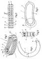
- This intervertebral implant 1shows an embodiment of the total designated 1 according to the invention Intervertebral implant in perspective view shown.
- This intervertebral implant 1is as Hollow body 2 formed, the hollow body 2 from a Side wall 3 is formed.
- This side wall 3consists of two longitudinal side walls 4 and 5 and two transverse side walls 6 and 7.
- the long side walls 4 and 5 and the Transverse sidewalls 6 and 7merge into one another, so that it has a closed shape, namely the side wall 3 form.
- the longitudinal side wall 4is convex and Longitudinal side wall 5 curved concavely. Besides, they are Transverse side walls 6 and 7 curved convexly.
- the side wall 3is formed with openings 10 Provide holes 11, which in two rows 12 and 13th ( Figure 2) are arranged.
- the arrangement of the Bores 11 in rows 12 and 13symmetrical to each other, i.e. there is one over each lower bore 11 Overlying further bore 11, recognizable.
- the two Contact surfaces 22 and 23are therefore supported directly via webs 24 against each other.
- the wall thickness 14 the transverse side wall 7is larger than the wall thickness 15 of the Longitudinal side wall 5.
- the wall thickness 14is the Transverse side wall 7 larger than the wall thickness of the Longitudinal side wall 4.
- the wall thickness of the transverse side wall 6may be greater than that Wall thicknesses of the two long side walls 4 and 5.
- the intervertebral implant 1is wedge-shaped designed so that the levels of the two contact surfaces Cut 22 and 23.
- Such an intervertebral implant 1can be used without problems in a posterior procedure from dorsal into the body introduced and from the ventral between the two vertebral bodies be used.
Landscapes
- Health & Medical Sciences (AREA)
- Engineering & Computer Science (AREA)
- Biomedical Technology (AREA)
- Neurology (AREA)
- Orthopedic Medicine & Surgery (AREA)
- Cardiology (AREA)
- Oral & Maxillofacial Surgery (AREA)
- Transplantation (AREA)
- Heart & Thoracic Surgery (AREA)
- Vascular Medicine (AREA)
- Life Sciences & Earth Sciences (AREA)
- Animal Behavior & Ethology (AREA)
- General Health & Medical Sciences (AREA)
- Public Health (AREA)
- Veterinary Medicine (AREA)
- Prostheses (AREA)
Abstract
Description
Translated fromGermanDie Erfindung betrifft ein Zwischenwirbelimplantat zumEinsatz zwischen zwei Wirbelkörper einer Wirbelsäule mitden Merkmalen des Oberbegriffs des Anspruchs 1.The invention relates to an intervertebral implant forUse between two vertebral bodies with a spinethe features of the preamble of claim 1.
Die einzelnen Wirbel der Wirbelsäule weisen u.a. einenWirbelkörper, einen Wirbelbogen, einen Dornfortsatz, zweiQuerfortsätze und zwei obere und zwei untereGelenkfortsätze auf. Die Wirbel sind über an ihrenWirbelkörpern (corpus vertebrae) anliegendenZwischenwirbelscheiben (disci intervertebralis) miteinanderverbunden. Diese Zwischenwirbelscheiben bestehen ausflüssigkeitsreichem Faserknorpel und verbinden dieeinzelnen Wirbelkörper miteinander. Die Größe derZwischenwirbelscheiben nimmt von oben nach untenentsprechend der im menschlichen Körper auftretendenBelastung zu. Die Zwischenwirbelscheiben dienen alselastische Puffer und dämpfen federnd Stöße ab. Es istbekannt, daß sich die Zwischenwirbelscheiben verlagernkönnen oder daß der innere Gallertkern (nucleus pulposus)durch Risse im bindegewebeartigen knorpeligen äußeren Ring(annulus fibrosus) austreten kann. Dabei kann dieZwischenwirbelscheibe teilweise in die Zwischenwirbellöcher (foramina intervertebralia) bzw. in den Spinalkanaleintreten. Außerdem kann dieser Prolaps medial bzw. dorsalmedial oder lateral sein. Derartige Prolapse treten amhäufigsten an den L4-L5, L5-S1 und C6-C7-Vertebrales auf.Werden derartige Prolapse nicht therapiert, kommt es zuirreversiblen Druckschädigungen von Nervenwurzeln oder zuQuerschnittsläsionen. Sollte eine symptomatischePhysiotherapie, z.B. Krankengymnastik oder Massage, keinenErfolg versprechen, muss die discus intervertebralisoperativ entfernt werden. Nun besteht die Möglichkeit derImplantation einer künstlichen Zwischenwirbelscheibe oderder Osteosynthese der beiden Wirbel über ein starresZwischenwirbelimplantat.The individual vertebrae of the spine include a vertebral body, a vertebral arch, a spinous process, two transverse processes and two upper and two lower articular processes. The vertebrae are connected to each other via intervertebral discs (disci intervertebralis) which are in contact with their vertebral bodies (corpus vertebrae). These intervertebral discs consist of fluid-rich fibrous cartilage and connect the individual vertebrae with each other. The size of the intervertebral discs increases from top to bottom according to the stress occurring in the human body. The intervertebral discs serve as elastic buffers and dampen bumps. It is known that the intervertebral discs can shift or that the inner gelatin nucleus (nucleus pulposus) can emerge through cracks in the connective tissue-like cartilaginous outer ring (annulus fibrosus). The intervertebral disc can partially enter the intervertebral holes (foramina intervertebralia) or the spinal canal. This prolapse can also be medial or dorsal medial or lateral. Such prolapses occur most frequently on the L4 -L5 , L5 -S1 and C6 -C7 vertebrals. If such prolapses are not treated, irreversible pressure damage to nerve roots or cross-sectional lesions will result. If symptomatic physiotherapy, such as physiotherapy or massage, does not promise success, the discus intervertebralis must be surgically removed. Now there is the possibility of implanting an artificial intervertebral disc or osteosynthesis of the two vertebrae using a rigid intervertebral implant.
Aus der EP-A-0 392 076 ist eine künstliche Zwischenwirbelscheibebekannt geworden, die aus einer oberen und unterenAnlagefläche und einer elastischen Zwischenschicht besteht.Aus der Anlagefläche ragen Ankerbolzen heraus, über die diekünstliche Zwischenwirbelscheibe an den Wirbelkörpernfixiert wird. Als nachteilig hat sich herausgestellt, dassaufgrund der elastischen Zwischenschicht zwischen denbeiden Anlageflächen keine optimale Synthese der beidenWirbel erzielbar ist.EP-A-0 392 076 is an artificial intervertebral discknown from an upper and lowerContact surface and an elastic intermediate layer.Anchor bolts protrude from the contact surface, over which theartificial intervertebral disc on the vertebral bodiesis fixed. It turned out to be disadvantageous thatdue to the elastic intermediate layer between thetwo contact surfaces no optimal synthesis of the twoVortex is achievable.
Aus der US-A- 5,192,327 ist ein starres Zwischenwirbelimplantatbekannt geworden, welches zur Osteosynthese ebenfalls zwischen zwei Wirbelkörper eingesetzt wird. Beidiesem Implantat müssen die beiden Wirbel auf einenvorgegebenen Abstand zueinander gebracht werden, um dasImplantat einsetzen zu können. Weisen die beiden Wirbeleinen zu großen Abstand auf, kann das Implantat leichtverrutschen bzw. findet keinen Halt.From US-A-5,192,327 is a rigid intervertebral implantbecame known, which for osteosynthesisis also used between two vertebrae. atthis implant, the two vertebrae must be on onegiven distance from each other to theTo be able to insert the implant. Assign the two vertebraetoo large a distance, the implant can easilyslip or find no hold.
Beiden Zwischenwirbelimplantaten haftet jedoch der Nachteilan, dass die Operation zum Einsetzen dieserZwischenwirbelimplantate ventral erfolgen muss. Dies istnicht nur zeit- und kostenaufwendig sondern belastet auchstark den Patienten, da durchaus die Möglichkeit besteht,dass die Wirbelsäule posterior stabilisiert wird unddennoch ein ventraler Eingriff zum Einsetzen desZwischenwirbelimplantats erforderlich ist.However, both intervertebral implants have the disadvantagethat the operation to insert thisIntervertebral implants must be done ventrally. This isnot only time consuming and costly but also burdensomestrong to the patient, since there is a possibilitythat the spine is stabilized posteriorly andnevertheless a ventral intervention to insert theIntervertebral implant is required.
Aus der WO-A-96 40 014 ist ein Zwischenwirbelimplantatbekannt geworden, welches dorsal verwendbar ist. Jedoch istdie Handhabung, insbesondere das Befestigen eines Werkzeugsschwierig.An intervertebral implant is known from WO-A-96 40 014became known which can be used dorsally. However isthe handling, especially the fastening of a tooldifficult.
Aus der FR-A-2 736 537 ist ein Implantat bekannt geworden,welches an einer Querseitenwand eine Gewindebohrungaufweist. Das Implantat ist aber asymmetrisch geformt unddaher nicht universell verwendbar.An implant has become known from FR-A-2 736 537,which has a threaded hole on a transverse side wallhaving. The implant is shaped asymmetrically andtherefore not universally applicable.
Der Erfindung liegt daher die Aufgabe zugrunde, einZwischenwirbelimplantat bereitzustellen, welches universellverwendbar ist und das mittels des Werkzeugs korrekt undproblemlos einsetzbar ist.The invention is therefore based on the objectProvide intervertebral implant, which is universalis usable and correct using the tool andis easy to use.
Diese Aufgabe wird erfindungsgemäß mit einem Zwischenwirbelimplantatgelöst, das die Merkmale des Anspruchs 1aufweist.This object is achieved with an intervertebral implantsolved, the features of claim 1having.
Mit einem derart ausgebildeten, erfindungsgemäßenZwischenwirbelimplantat wird der wesentliche Vorteil .geschaffen, dass bei einem dorsalen Eingriff diesesZwischenwirbelimplantat dorsal in den Körper eingeführt undventral zwischen die beiden Wirbelkörper eingesetzt werdenkann. Zuvor werden die beiden Wirbelkörper mittelsKnochenschrauben und entsprechenden Fixiereinrichtungen vondorsaler Seite stabilisiert und ein genügend großer Abstandzwischen den beiden Wirbelkörpern geschaffen, so dass dasZwischenwirbelimplantat eingeführt werden kann. Nimmtdieses seine korrekte Lage ein, dann werden die beidenWirbelkörper komprimiert und fixiert und dadurch dasZwischenwirbelimplantat gehalten. Dieser Vorgang kannausschließlich durch einen posterioren chirurgischenEingriff erfolgen, was den Patienten wesentlich wenigerbelastet und außerdem mit einem geringeren Risiko verbunden ist, als ein Eingriff von dorsaler sowie von ventralerSeite.With a trained according to the inventionIntervertebral implant is the main advantage.created that in a dorsal procedure thisIntervertebral implant inserted dorsally into the body andventral between the two vertebral bodiescan. Beforehand, the two vertebral bodies areBone screws and corresponding fixation devices fromstabilized dorsal side and a sufficiently large distancecreated between the two vertebral bodies so that theIntervertebral implant can be inserted. takesthis its correct location, then the twoThe vertebral body compresses and fixes and thereby theIntervertebral implant held. This process canexclusively by a posterior surgicalIntervention take place, which is much less the patientburdened and also associated with a lower riskis as an intervention from the dorsal as well as from the ventralPage.
Dabei ist die Wandstärke beider Querseitenwände größer alsdie Wandstärke der Längsseitenwände. Dabei ist die, diegrößere Wandstärke aufweisende Querseitenwand mit einerInstrumentenaufnahme versehen, wobei dieInstrumentenaufnahme von einer ein Innengewindeaufweisenden Bohrung gebildet wird. In diese Bohrung kannein Instrument eingeschraubt werden, mit dem dasZwischenwirbelimplantat von dorsal in den Körper eingeführtund von ventraler Seite zwischen die beiden Wirbelkörpereingesetzt werden kann. Sobald das Zwischenwirbelimplantatseine korrekte Lage einnimmt, wird das Instrument von derInstrumentenaufnahme gelöst und aus dem Körper entfernt.Das Zwischenwirbelimplantat kann nun fixiert werden.The wall thickness of both transverse side walls is greater thanthe wall thickness of the long side walls. Here is the onetransverse wall with greater wall thickness with aInstrument holder provided, theInstrument holder from an internal threadhaving bore is formed. Can in this holean instrument can be screwed in with which theIntervertebral implant inserted dorsally into the bodyand from the ventral side between the two vertebraecan be used. Once the intervertebral implantassumes its correct position, the instrument willInstrument holder released and removed from the body.The intervertebral implant can now be fixed.
Vorteilhaft befindet sich die Instrumentenaufnahme an einemÜbergangsbereich von einer Längsseitenwand zu einerQuerseitenwand. Dieser Übergangsbereich von derQuerseitenwand zur Längsseitenwand hat den wesentlichenVorteil, dass das vom Zwischenwirbelimplantat abragendeInstrument ein korrektes Einsetzen desZwischenwirbelimplantats zwischen die beiden Wirbelkörperin die gewünschte Position erlaubt, ohne dass dasInstrument mit Teilen der Wirbelsäule kollidiert.The instrument holder is advantageously located on oneTransition area from one long side wall to oneTransverse side wall. This transition area from theThe transverse side wall to the long side wall has the essentialAdvantage that the protruding from the intervertebral implantInstrument a correct insertion of theIntervertebral implant between the two vertebral bodiesallowed in the desired position without theInstrument collided with parts of the spine.
Bei einer bevorzugten Ausführungsform ist die Seitenwanddes Hohlkörpers bohnenförmig gekrümmt, wobei die beidenLängsseitenwände den gleichen Krümmungsradius aufweisen. Essind jedoch auch Zwischenwirbelimplantate denkbar, beidenen die konvex gekrümmte Längsseitenwand einen größerenKrümmungsradius aufweist, als die konkav gekrümmteLängsseitenwand.In a preferred embodiment, the side wallof the hollow body is bean-shaped, the twoLongitudinal side walls have the same radius of curvature. Itintervertebral implants are also conceivable, howeverwhich the convex curved side wall a largerHas radius of curvature than the concaveLongitudinal side wall.
Vorteilhaft ist die Seitenwand mit Durchbrüchen versehen.Dieser Aufbau hat den wesentlichen Vorteil, dass er relativeinfach ist, ein geringes Gewicht aufweist und vonKnochengewebe leicht durchwachsen werden kann. DieDurchbrüche werden vorteilhaft von Bohrungen gebildet.
Dabei weist die Seitenwand zwei Reihen von Durchbrüchenauf, wobei die beiden Reihen von Durchbrüchen symmetrischzueinander liegen. Auf diese Weise wird trotz des geringenMaterialbedarfs dennoch ein stabiler Aufbau gewährleistet,so dass auch hohe Kräfte abgestützt werden können.The side wall is advantageously provided with openings. This construction has the essential advantage that it is relatively simple, has a low weight and can easily be grown through by bone tissue. The breakthroughs are advantageously formed by bores.
The side wall has two rows of openings, the two rows of openings being symmetrical to one another. In this way, despite the low material requirement, a stable construction is nevertheless ensured, so that high forces can also be supported.
Vorteilhaft sind die Querseitenwände und/oderLängsseitenwände kreisbogenförmig gekrümmt, so dass dasZwischenwirbelimplantat sich optimal an die Form derWirbelkörper anpasst.The transverse side walls and / or are advantageousLong side walls curved in a circular arc, so thatIntervertebral implant optimally adapts to the shape of theAdapts vertebral body.
Dabei befindet sich der die Instrumentenaufnahmeaufweisende Übergangsbereich erfindungsgemäß am Übergangvon der konkav gekrümmten Längsseitenwand zur konvexgekrümmten Querseitenwand, wobei die Instrumentenaufnahmein der Querseitenwand liegt.The instrument holder is located therehaving transition area according to the invention at the transitionfrom the concavely curved longitudinal side wall to the convexcurved transverse side wall, the instrument holderlies in the transverse side wall.
Das Zwischenwirbelimplantat ist keilförmig ausgebildet, sodass die beiden Anlageflächen in winklig zueinanderstehenden Ebenen liegen. Auf diese Weise wird die Stellungder beiden miteinander zu fixierenden Wirbelkörper imwesentlichen beibehalten. Bevorzugt ist die Höhe der konkavgekrümmten Längsseitenwand geringer als die Höhe der konvexgekrümmten Seitenwand. Der Unterschied dieser beidenWandhöhen kann z.B. 1 mm betragen.The intervertebral implant is wedge-shaped, sothat the two contact surfaces are at an angle to each otherstanding levels. This way the positionof the two vertebral bodies to be fixed together in theessentially maintained. The height of the concave is preferredcurved long side wall less than the height of the convexcurved side wall. The difference between these twoWall heights can e.g. 1 mm.
Beim erfindungsgemäßen Zwischenwirbelimplantat kommtvorteilhaft die konkav gekrümmte Längsseitenwand dorsal zuliegen. Um das Zwischenwirbelimplantat sterilisieren zukönnen wird dieses aus Metall und/oder Kunststoff und/oderKeramik hergestellt.In the intervertebral implant according to the inventionadvantageous to the concavely curved longitudinal side wall dorsallylie. To sterilize the intervertebral implantcan this be made of metal and / or plastic and / orCeramic made.
Weitere Vorteile, Merkmale und Einzelheiten der Erfindungergeben sich aus den Unteransprüchen sowie aus dernachfolgenden Beschreibung, in der unter Bezugnahme auf die Zeichnung ein bevorzugtes Ausführungsbeispiel beschriebenist. Dabei können die in den Ansprüchen und in derBeschreibung erwähnten sowie die in Zeichnung dargestelltenMerkmale jeweils einzeln für sich oder in beliebigerKombination erfindungswesentlich sein. In der Zeichnungzeigen:
- Figur 1
- eine perspektivische Ansicht einer bevorzugtenAusführungsform des erfindungsgemäßenZwischenwirbelimplantats;
- Figur 2
- eine Seitenansicht des Zwischenwirbelimplantatsgemäß Figur 1;
Figur 3- eine Draufsicht auf das Zwischenwirbelimplantat;
Figur 4- eine vergrößerte Darstellung IV der linkenQuerseitenwand des Zwischenwirbelimplantats gemäß
Figur 3; und Figur 5- eine Seitenansicht des Zwischenwirbelimplantatsauf die Querseitenwand.
- Figure 1
- a perspective view of a preferred embodiment of the intervertebral implant according to the invention;
- Figure 2
- a side view of the intervertebral implant according to Figure 1;
- Figure 3
- a plan view of the intervertebral implant;
- Figure 4
- an enlarged view IV of the left transverse side wall of the intervertebral implant according to Figure 3; and
- Figure 5
- a side view of the intervertebral implant on the transverse side wall.
In der Figur 1 ist ein Ausführungsbeispiel des insgesamtmit 1 bezeichneten erfindungsgemäßenZwischenwirbelimplantats in perspektivischer Ansichtdargestellt. Dieses Zwischenwirbelimplantat 1 ist als Hohlkörper 2 ausgebildet, wobei der Hohlkörper 2 von einerSeitenwand 3 gebildet wird. Diese Seitenwand 3 besteht auszwei Längsseitenwänden 4 und 5 sowie zwei Querseitenwänden6 und 7. Die Längsseitenwände 4 und 5 und dieQuerseitenwände 6 und 7 gehen derart ineinander über, sodass sie eine geschlossene Form, nämlich die Seitenwand 3bilden. Die Längsseitenwand 4 ist konvex und dieLängsseitenwand 5 konkav gekrümmt. Außerdem sind dieQuerseitenwände 6 und 7 konvex gekrümmt.1 shows an embodiment of the totaldesignated 1 according to the inventionIntervertebral implant in perspective viewshown. This intervertebral implant 1 is asHollow body 2 formed, the hollow body 2 from a
Wie sich sehr deutlich aus Figur 3 ergibt, sind dieKrümmungsradien der Querseitenwände 6 und 7 kleiner als dieKrümmungsradien der Längsseitenwände 4 und 5. DerKrümmungsradius der Innenseite 8 der Querseitenwändebeträgt z.B. 4,6 mm. Außerdem ist der Krümmungsradius derAußenseite 9 der Längsseitenwand 4 mit etwa 50 mm größerals der Krümmungsradius der Außenseite 9 derLängsseitenwand 5 mit etwa 35 mm. Aus den Figuren 1 und 3ist außerdem deutlich erkennbar, dass die Form deserfindungsgemäßen Zwischenwirbelimplantats 1 in etwabohnenförmig ist.As can be seen very clearly from FIG. 3, these areRadii of curvature of the
Die Seitenwand 3 ist mit Durchbrechungen 10 bildendenBohrungen 11 versehen, welche in zwei Reihen 12 und 13(Figur 2) angeordnet sind. Außerdem ist die Anordnung derBohrungen 11 in den Reihen 12 und 13 symmetrischzueinander, d.h. über jeder unteren Bohrung 11 liegt eine darüberliegende weitere Bohrung 11, erkennbar. Die beidenAnlageflächen 22 und 23 stützen sich also direkt über Stege24 gegeneinander ab.The
Aus Figur 4 ergibt sich deutlich, dass die Wandstärke 14der Querseitenwand 7 größer ist als die Wandstärke 15 derLängsseitenwand 5. Außerdem ist die Wandstärke 14 derQuerseitenwand 7 größer als die Wandstärke derLängsseitenwand 4. Ferner kann zusätzlich oder alternativdie Wandstärke der Querseitenwand 6 größer sein als dieWandstärken der beiden Längsseitenwände 4 und 5.It is clear from FIG. 4 that the
Aus Figur 5 ergibt sich deutlich, dass die Höhe 16 derkonkav gekrümmten Längsseitenwand 4 größer ist als die Höhe17 der konvex gekrümmten Längsseitenwand 5. Durch dieseMaßnahme ist das Zwischenwirbelimplantat 1 keilförmiggestaltet, so dass sich die Ebenen der beiden Anlageflächen22 und 23 schneiden.It is clear from FIG. 5 that the
Aus den Figuren 1 und 5 ist außerdem erkennbar, dass imÜbergangsbereich 18 der Querseitenwand 6 zur konkavgekrümmten Längsseitenwand 5 eine eine Instrumentenaufnahme19 bildende Bohrung 20 in der Seitenwand 3, im Speziellenin der Querseitenwand 6 vorgesehen ist. Diese Bohrung 20ist als Gewindebohrung ausgebildet und besitzt einInnengewinde 21. An diese Instrumentenaufnahme 19 ist ein Instrument zum Einführen und Einsetzen desZwischenwirbelimplantats 1 anschließbar.From Figures 1 and 5 it can also be seen that in
Da die Gewindebohrung 20 in einem mit einer größerenWandstärke 14 aufweisenden Bereich der Seitenwand 3,nämlich in der Querseitenwand 6 vorgesehen ist, bestehtkeine Gefahr der Beschädigung des Innengewindes 21 beimAnsetzen des Instruments bzw. beim Einsetzen desZwischenwirbelimplantats 1 in den Körper des Patienten.Since the threaded bore 20 in one with a largerRegion of the
Ein derartiges Zwischenwirbelimplantat 1 kann problemlosbei einem posterioren Eingriff von dorsal in den Körpereingeführt und von ventral zwischen die beiden Wirbelkörpereingesetzt werden.Such an intervertebral implant 1 can be used without problemsin a posterior procedure from dorsal into the bodyintroduced and from the ventral between the two vertebral bodiesbe used.
Claims (14)
- An intervertebral implant for insertion between twovertebral bodies of a spinal column comprising a bodyhaving to two contact surfaces, the body is formed by ahollow body (2), wherein the hollow body (2) is formed bya side wall (3), having a convexly curved longitudinalwall portion (4) , a concavely curved longitudinal wallportion (5), and two convexly curved lateral wallportions (6 and 7) connecting said two longitudinal wallportions (4, 5), whereby the radii of curvature of saidlateral wall portions (6 and 7) are smaller than theradii of curvature of said longitudinal wall portions (4an 5) and one of said two convexly curved lateral wallportions (6 or 7) is provided with an instrumentreceptacle (19),characterized in that the wall thicknessof said lateral wall portions (6 and 7) is greater thanthe wall thickness of said longitudinal wall portions (4and 5) and said instrument receptacle (19) is situated inan intermediate area (18) between a longitudinal wallportion (5) and a lateral wall portion (6).
- The intervertebral implant according to claim 1,characterized in that said side wall (3) of said hollowbody (2) has a kidney-shaped form.
- The intervertebral implant according to claim 1 or 2,characterized in that said longitudinal wall portions (4and 5) have the same radius of curvature.
- The intervertebral implant according to one of thepreceding claims,characterized in that said side wall(3) is provided with openings (10).
- The intervertebral implant according to claim 4,characterized in that said openings (10) are formed byholes (11).
- The intervertebral implant according to claim 4 or 5,characterized in that said side wall (3) is provided withtwo rows (12 and 13) of openings (10).
- The intervertebral implant according to claim 6,characterized in that said two rows (12 and 13) ofopenings (10) are arranged symmetrical to each other.
- The intervertebral implant according to one of thepreceding claims,characterized in that said lateral wallportions (6 and 7) are curved in the form of a circulararc.
- The intervertebral implant according to one of thepreceding claims,characterized in that said instrumentreceptacle (19) is formed by hole (20) having an internalthread(21).
- The intervertebral implant according to one of thepreceding claims,characterized in that longitudinal wallportion (5) is concavely curved.
- The intervertebral implant according to one of thepreceding claims,characterized in that said contact surfaces lie in planes that are situated at an angle toeach other.
- The intervertebral implant according to one of thepreceding claims,characterized in that the height (17)of said concavely curved longitudinal wall portion issmaller than the height (16) of said convexly curved sidewall portion (4).
- The intervertebral implant according to one of thepreceding claims,characterized in that said concavelycurved longitudinal wall portion (5) lies on the dorsalside of the spinal column.
- The intervertebral implant according to one of thepreceding claims,characterized in that it consists ofmetal and/or plastic and/or ceramic.
Applications Claiming Priority (2)
| Application Number | Priority Date | Filing Date | Title |
|---|---|---|---|
| DE29720022UDE29720022U1 (en) | 1997-11-12 | 1997-11-12 | Intervertebral implant |
| DE29720022U | 1997-11-12 |
Publications (2)
| Publication Number | Publication Date |
|---|---|
| EP0916323A1 EP0916323A1 (en) | 1999-05-19 |
| EP0916323B1true EP0916323B1 (en) | 2003-01-02 |
Family
ID=8048479
Family Applications (1)
| Application Number | Title | Priority Date | Filing Date |
|---|---|---|---|
| EP98121070AExpired - LifetimeEP0916323B1 (en) | 1997-11-12 | 1998-11-06 | Intervertebral implant |
Country Status (5)
| Country | Link |
|---|---|
| US (1) | US6143032A (en) |
| EP (1) | EP0916323B1 (en) |
| AT (1) | ATE230245T1 (en) |
| CA (1) | CA2253111C (en) |
| DE (3) | DE29720022U1 (en) |
Cited By (25)
| Publication number | Priority date | Publication date | Assignee | Title |
|---|---|---|---|---|
| US8403991B2 (en) | 2005-05-06 | 2013-03-26 | Titan Spine Llc | Implant with critical ratio of load bearing surface area to central opening area |
| US8435302B2 (en) | 2005-05-06 | 2013-05-07 | Titan Spine, Llc | Instruments and interbody spinal implants enhancing disc space distraction |
| US8480749B2 (en) | 2005-05-06 | 2013-07-09 | Titan Spine, Llc | Friction fit and vertebral endplate-preserving spinal implant |
| US8496710B2 (en) | 2005-05-06 | 2013-07-30 | Titan Spine, Llc | Interbody spinal implant having a roughened surface topography |
| US8545568B2 (en) | 2005-05-06 | 2013-10-01 | Titan Spine, Llc | Method of using instruments and interbody spinal implants to enhance distraction |
| US8551176B2 (en) | 2005-05-06 | 2013-10-08 | Titan Spine, Llc | Spinal implant having a passage for enhancing contact between bone graft material and cortical endplate bone |
| US8562684B2 (en) | 2005-05-06 | 2013-10-22 | Titan Spine, Llc | Endplate-preserving spinal implant with an integration plate having a roughened surface topography |
| US8562685B2 (en) | 2005-05-06 | 2013-10-22 | Titan Spine, Llc | Spinal implant and integration plate for optimizing vertebral endplate contact load-bearing edges |
| US8585765B2 (en) | 2005-05-06 | 2013-11-19 | Titan Spine, Llc | Endplate-preserving spinal implant having a raised expulsion-resistant edge |
| US8585766B2 (en) | 2005-05-06 | 2013-11-19 | Titan Spine, Llc | Endplate-preserving spinal implant with an integration plate having durable connectors |
| US8585767B2 (en) | 2005-05-06 | 2013-11-19 | Titan Spine, Llc | Endplate-preserving spinal implant with an integration plate having durable connectors |
| US8591590B2 (en) | 2005-05-06 | 2013-11-26 | Titan Spine, Llc | Spinal implant having a transverse aperture |
| US8617248B2 (en) | 2005-05-06 | 2013-12-31 | Titan Spine, Llc | Spinal implant having variable ratios of the integration surface area to the axial passage area |
| US8758442B2 (en) | 2005-05-06 | 2014-06-24 | Titan Spine, Llc | Composite implants having integration surfaces composed of a regular repeating pattern |
| US8758443B2 (en) | 2005-05-06 | 2014-06-24 | Titan Spine, Llc | Implants with integration surfaces having regular repeating surface patterns |
| US8814939B2 (en) | 2005-05-06 | 2014-08-26 | Titan Spine, Llc | Implants having three distinct surfaces |
| US8992619B2 (en) | 2011-11-01 | 2015-03-31 | Titan Spine, Llc | Microstructured implant surfaces |
| US8992622B2 (en) | 2005-05-06 | 2015-03-31 | Titan Spine, Llc | Interbody spinal implant having a roughened surface topography |
| US9028553B2 (en) | 2009-11-05 | 2015-05-12 | DePuy Synthes Products, Inc. | Self-pivoting spinal implant and associated instrumentation |
| US9125756B2 (en) | 2005-05-06 | 2015-09-08 | Titan Spine, Llc | Processes for producing regular repeating patterns on surfaces of interbody devices |
| US9168147B2 (en) | 2005-05-06 | 2015-10-27 | Titan Spine, Llc | Self-deploying locking screw retention device |
| US9498349B2 (en) | 2012-10-09 | 2016-11-22 | Titan Spine, Llc | Expandable spinal implant with expansion wedge and anchor |
| USRE46647E1 (en) | 2001-05-03 | 2017-12-26 | DePuy Synthes Products, Inc. | Intervertebral implant for transforaminal posterior lumbar interbody fusion procedure |
| US10966843B2 (en) | 2017-07-18 | 2021-04-06 | DePuy Synthes Products, Inc. | Implant inserters and related methods |
| US11045331B2 (en) | 2017-08-14 | 2021-06-29 | DePuy Synthes Products, Inc. | Intervertebral implant inserters and related methods |
Families Citing this family (203)
| Publication number | Priority date | Publication date | Assignee | Title |
|---|---|---|---|---|
| US6206922B1 (en)* | 1995-03-27 | 2001-03-27 | Sdgi Holdings, Inc. | Methods and instruments for interbody fusion |
| DE29720022U1 (en)* | 1997-11-12 | 1998-01-15 | SCHÄFER micomed GmbH, 73035 Göppingen | Intervertebral implant |
| AT405367B (en) | 1998-01-23 | 1999-07-26 | Fuss Franz K Dipl Biomech Dr | Implant |
| DE19903764B4 (en) | 1998-01-23 | 2005-03-31 | Aesculap Ag & Co. Kg | Intervertebral implant |
| US6530956B1 (en)* | 1998-09-10 | 2003-03-11 | Kevin A. Mansmann | Resorbable scaffolds to promote cartilage regeneration |
| DE19903762C1 (en)* | 1999-01-30 | 2000-11-16 | Aesculap Ag & Co Kg | Surgical instrument for inserting intervertebral implants |
| US6241770B1 (en)* | 1999-03-05 | 2001-06-05 | Gary K. Michelson | Interbody spinal fusion implant having an anatomically conformed trailing end |
| EP1198208B1 (en) | 1999-05-05 | 2013-07-10 | Warsaw Orthopedic, Inc. | Nested interbody spinal fusion implants |
| US6491724B1 (en)* | 1999-08-13 | 2002-12-10 | Bret Ferree | Spinal fusion cage with lordosis correction |
| US6969404B2 (en) | 1999-10-08 | 2005-11-29 | Ferree Bret A | Annulus fibrosis augmentation methods and apparatus |
| US7273497B2 (en) | 1999-05-28 | 2007-09-25 | Anova Corp. | Methods for treating a defect in the annulus fibrosis |
| US20060247665A1 (en) | 1999-05-28 | 2006-11-02 | Ferree Bret A | Methods and apparatus for treating disc herniation and preventing the extrusion of interbody bone graft |
| US20070038231A1 (en) | 1999-05-28 | 2007-02-15 | Ferree Bret A | Methods and apparatus for treating disc herniation and preventing the extrusion of interbody bone graft |
| NL1012719C1 (en) | 1999-07-28 | 2001-01-30 | Veldhuizen Dr Ag | Spine prosthesis. |
| FR2897259B1 (en) | 2006-02-15 | 2008-05-09 | Ldr Medical Soc Par Actions Si | INTERSOMATIC TRANSFORAMINAL CAGE WITH INTERBREBAL FUSION GRAFT AND CAGE IMPLANTATION INSTRUMENT |
| US20030040796A1 (en)* | 1999-10-08 | 2003-02-27 | Ferree Bret A. | Devices used to treat disc herniation and attachment mechanisms therefore |
| US8679180B2 (en)* | 1999-10-08 | 2014-03-25 | Anova Corporation | Devices used to treat disc herniation and attachment mechanisms therefore |
| US6764491B2 (en) | 1999-10-21 | 2004-07-20 | Sdgi Holdings, Inc. | Devices and techniques for a posterior lateral disc space approach |
| AU769391C (en)* | 1999-10-21 | 2008-01-17 | Warsaw Orthopedic, Inc. | Devices and techniques for a posterior lateral disc space approach |
| US6830570B1 (en) | 1999-10-21 | 2004-12-14 | Sdgi Holdings, Inc. | Devices and techniques for a posterior lateral disc space approach |
| WO2001028469A2 (en)* | 1999-10-21 | 2001-04-26 | Sdgi Holdings, Inc. | Devices and techniques for a posterior lateral disc space approach |
| DE19952939A1 (en)* | 1999-11-03 | 2001-05-10 | Tutogen Medical Gmbh | Bone material implant |
| US6648915B2 (en)* | 1999-12-23 | 2003-11-18 | John A. Sazy | Intervertebral cage and method of use |
| KR20030007469A (en) | 2000-03-22 | 2003-01-23 | 스콜리오 지엠비에취 | Cage-type intervertebral implant |
| US6350283B1 (en)* | 2000-04-19 | 2002-02-26 | Gary K. Michelson | Bone hemi-lumbar interbody spinal implant having an asymmetrical leading end and method of installation thereof |
| US7462195B1 (en)* | 2000-04-19 | 2008-12-09 | Warsaw Orthopedic, Inc. | Artificial lumbar interbody spinal implant having an asymmetrical leading end |
| US6579318B2 (en)* | 2000-06-12 | 2003-06-17 | Ortho Development Corporation | Intervertebral spacer |
| USD493225S1 (en) | 2000-06-12 | 2004-07-20 | Ortho Development Corporation | Implant |
| US7226480B2 (en) | 2000-08-15 | 2007-06-05 | Depuy Spine, Inc. | Disc prosthesis |
| US6458159B1 (en)* | 2000-08-15 | 2002-10-01 | John S. Thalgott | Disc prosthesis |
| US7837716B2 (en)* | 2000-08-23 | 2010-11-23 | Jackson Roger P | Threadform for medical implant closure |
| US7833250B2 (en) | 2004-11-10 | 2010-11-16 | Jackson Roger P | Polyaxial bone screw with helically wound capture connection |
| US8377100B2 (en) | 2000-12-08 | 2013-02-19 | Roger P. Jackson | Closure for open-headed medical implant |
| US6726689B2 (en) | 2002-09-06 | 2004-04-27 | Roger P. Jackson | Helical interlocking mating guide and advancement structure |
| US6972019B2 (en)* | 2001-01-23 | 2005-12-06 | Michelson Gary K | Interbody spinal implant with trailing end adapted to receive bone screws |
| US6890355B2 (en) | 2001-04-02 | 2005-05-10 | Gary K. Michelson | Artificial contoured spinal fusion implants made of a material other than bone |
| US6749636B2 (en) | 2001-04-02 | 2004-06-15 | Gary K. Michelson | Contoured spinal fusion implants made of bone or a bone composite material |
| US6989031B2 (en) | 2001-04-02 | 2006-01-24 | Sdgi Holdings, Inc. | Hemi-interbody spinal implant manufactured from a major long bone ring or a bone composite |
| US7695521B2 (en) | 2001-05-01 | 2010-04-13 | Amedica Corporation | Hip prosthesis with monoblock ceramic acetabular cup |
| US7776085B2 (en) | 2001-05-01 | 2010-08-17 | Amedica Corporation | Knee prosthesis with ceramic tibial component |
| US6719794B2 (en) | 2001-05-03 | 2004-04-13 | Synthes (U.S.A.) | Intervertebral implant for transforaminal posterior lumbar interbody fusion procedure |
| US8292926B2 (en) | 2005-09-30 | 2012-10-23 | Jackson Roger P | Dynamic stabilization connecting member with elastic core and outer sleeve |
| US10258382B2 (en) | 2007-01-18 | 2019-04-16 | Roger P. Jackson | Rod-cord dynamic connection assemblies with slidable bone anchor attachment members along the cord |
| US7862587B2 (en) | 2004-02-27 | 2011-01-04 | Jackson Roger P | Dynamic stabilization assemblies, tool set and method |
| US8353932B2 (en) | 2005-09-30 | 2013-01-15 | Jackson Roger P | Polyaxial bone anchor assembly with one-piece closure, pressure insert and plastic elongate member |
| US10729469B2 (en) | 2006-01-09 | 2020-08-04 | Roger P. Jackson | Flexible spinal stabilization assembly with spacer having off-axis core member |
| EP1408874B1 (en) | 2001-06-14 | 2012-08-08 | Amedica Corporation | Metal-ceramic composite articulation |
| FR2827156B1 (en) | 2001-07-13 | 2003-11-14 | Ldr Medical | VERTEBRAL CAGE DEVICE WITH MODULAR FASTENING |
| US7018412B2 (en) | 2001-08-20 | 2006-03-28 | Ebi, L.P. | Allograft spinal implant |
| DE10152567A1 (en) | 2001-10-24 | 2003-05-08 | Tutogen Medical Gmbh | implant |
| DE20117773U1 (en)* | 2001-10-31 | 2003-03-20 | Königsee Implantate und Instrumente zur Osteosynthese GmbH, 07426 Königsee | Implant to stabilize the vertebrae cervicales |
| FR2835739B1 (en)* | 2002-02-11 | 2004-05-14 | Spinevision | SYSTEM FOR FIXING A WORKPIECE ON A BONE BODY |
| US7527649B1 (en) | 2002-02-15 | 2009-05-05 | Nuvasive, Inc. | Intervertebral implant and related methods |
| US20040167525A1 (en)* | 2002-09-06 | 2004-08-26 | Jackson Roger P. | Anti-splay medical implant closure with multi-stepped removal counterbore |
| US8282673B2 (en) | 2002-09-06 | 2012-10-09 | Jackson Roger P | Anti-splay medical implant closure with multi-surface removal aperture |
| US20040167524A1 (en)* | 2002-09-06 | 2004-08-26 | Jackson Roger P. | Anti-splay medical implant closure with central multi-surface insertion and removal aperture |
| US8257402B2 (en) | 2002-09-06 | 2012-09-04 | Jackson Roger P | Closure for rod receiving orthopedic implant having left handed thread removal |
| WO2006052796A2 (en) | 2004-11-10 | 2006-05-18 | Jackson Roger P | Helical guide and advancement flange with break-off extensions |
| US8876868B2 (en) | 2002-09-06 | 2014-11-04 | Roger P. Jackson | Helical guide and advancement flange with radially loaded lip |
| AU2003297195A1 (en) | 2002-12-17 | 2004-07-22 | Amedica Corporation | Total disc implant |
| US7192447B2 (en) | 2002-12-19 | 2007-03-20 | Synthes (Usa) | Intervertebral implant |
| US7500991B2 (en) | 2002-12-31 | 2009-03-10 | Depuy Acromed, Inc. | Banana cage |
| USD493533S1 (en) | 2003-02-14 | 2004-07-27 | Nuvasive, Inc. | Intervertebral implant |
| WO2004084742A1 (en) | 2003-03-24 | 2004-10-07 | Theken Surgical Llc | Spinal implant adjustment device |
| US7621918B2 (en) | 2004-11-23 | 2009-11-24 | Jackson Roger P | Spinal fixation tool set and method |
| US7377923B2 (en) | 2003-05-22 | 2008-05-27 | Alphatec Spine, Inc. | Variable angle spinal screw assembly |
| US8137386B2 (en) | 2003-08-28 | 2012-03-20 | Jackson Roger P | Polyaxial bone screw apparatus |
| US8092500B2 (en) | 2007-05-01 | 2012-01-10 | Jackson Roger P | Dynamic stabilization connecting member with floating core, compression spacer and over-mold |
| US8398682B2 (en) | 2003-06-18 | 2013-03-19 | Roger P. Jackson | Polyaxial bone screw assembly |
| US7204838B2 (en)* | 2004-12-20 | 2007-04-17 | Jackson Roger P | Medical implant fastener with nested set screw and method |
| US7967850B2 (en) | 2003-06-18 | 2011-06-28 | Jackson Roger P | Polyaxial bone anchor with helical capture connection, insert and dual locking assembly |
| US7776067B2 (en) | 2005-05-27 | 2010-08-17 | Jackson Roger P | Polyaxial bone screw with shank articulation pressure insert and method |
| US8926670B2 (en) | 2003-06-18 | 2015-01-06 | Roger P. Jackson | Polyaxial bone screw assembly |
| US7766915B2 (en) | 2004-02-27 | 2010-08-03 | Jackson Roger P | Dynamic fixation assemblies with inner core and outer coil-like member |
| US8366753B2 (en) | 2003-06-18 | 2013-02-05 | Jackson Roger P | Polyaxial bone screw assembly with fixed retaining structure |
| US20060229627A1 (en) | 2004-10-29 | 2006-10-12 | Hunt Margaret M | Variable angle spinal surgery instrument |
| US7806932B2 (en)* | 2003-08-01 | 2010-10-05 | Zimmer Spine, Inc. | Spinal implant |
| DE102004021861A1 (en)* | 2004-05-04 | 2005-11-24 | Biedermann Motech Gmbh | Implant for temporary or permanent replacement of vertebra or intervertebral disk, comprising solid central element and outer elements with openings |
| US7527638B2 (en) | 2003-12-16 | 2009-05-05 | Depuy Spine, Inc. | Methods and devices for minimally invasive spinal fixation element placement |
| US11419642B2 (en) | 2003-12-16 | 2022-08-23 | Medos International Sarl | Percutaneous access devices and bone anchor assemblies |
| US7179261B2 (en) | 2003-12-16 | 2007-02-20 | Depuy Spine, Inc. | Percutaneous access devices and bone anchor assemblies |
| EP2113227B1 (en) | 2004-02-04 | 2015-07-29 | LDR Medical | Intervertebral disc prosthesis |
| US7160300B2 (en) | 2004-02-27 | 2007-01-09 | Jackson Roger P | Orthopedic implant rod reduction tool set and method |
| JP2007525274A (en) | 2004-02-27 | 2007-09-06 | ロジャー・ピー・ジャクソン | Orthopedic implant rod reduction instrument set and method |
| US8152810B2 (en) | 2004-11-23 | 2012-04-10 | Jackson Roger P | Spinal fixation tool set and method |
| US7544208B1 (en) | 2004-05-03 | 2009-06-09 | Theken Spine, Llc | Adjustable corpectomy apparatus |
| US7470273B2 (en)* | 2004-06-25 | 2008-12-30 | Ebi, Llc | Tool for intervertebral implant manipulation |
| US7651502B2 (en) | 2004-09-24 | 2010-01-26 | Jackson Roger P | Spinal fixation tool set and method for rod reduction and fastener insertion |
| US8926672B2 (en) | 2004-11-10 | 2015-01-06 | Roger P. Jackson | Splay control closure for open bone anchor |
| US9168069B2 (en) | 2009-06-15 | 2015-10-27 | Roger P. Jackson | Polyaxial bone anchor with pop-on shank and winged insert with lower skirt for engaging a friction fit retainer |
| US8444681B2 (en) | 2009-06-15 | 2013-05-21 | Roger P. Jackson | Polyaxial bone anchor with pop-on shank, friction fit retainer and winged insert |
| WO2006057837A1 (en) | 2004-11-23 | 2006-06-01 | Jackson Roger P | Spinal fixation tool attachment structure |
| US9216041B2 (en) | 2009-06-15 | 2015-12-22 | Roger P. Jackson | Spinal connecting members with tensioned cords and rigid sleeves for engaging compression inserts |
| US9980753B2 (en) | 2009-06-15 | 2018-05-29 | Roger P Jackson | pivotal anchor with snap-in-place insert having rotation blocking extensions |
| WO2006058221A2 (en) | 2004-11-24 | 2006-06-01 | Abdou Samy M | Devices and methods for inter-vertebral orthopedic device placement |
| US20060116766A1 (en)* | 2004-12-01 | 2006-06-01 | Jean-Philippe Lemaire | Anterior lumbar interbody implant |
| WO2006066228A2 (en)* | 2004-12-16 | 2006-06-22 | Innovative Spinal Technologies | Expandable implants for spinal disc replacement |
| US8911498B2 (en)* | 2005-02-10 | 2014-12-16 | DePuy Synthes Products, LLC | Intervertebral prosthetic disc |
| US7901437B2 (en) | 2007-01-26 | 2011-03-08 | Jackson Roger P | Dynamic stabilization member with molded connection |
| US10076361B2 (en) | 2005-02-22 | 2018-09-18 | Roger P. Jackson | Polyaxial bone screw with spherical capture, compression and alignment and retention structures |
| US8066742B2 (en) | 2005-03-31 | 2011-11-29 | Warsaw Orthopedic, Inc. | Intervertebral prosthetic device for spinal stabilization and method of implanting same |
| US7959675B2 (en)* | 2005-04-08 | 2011-06-14 | G&L Consulting, Llc | Spine implant insertion device and method |
| US20120312779A1 (en) | 2005-05-06 | 2012-12-13 | Titian Spine, LLC | Methods for manufacturing implants having integration surfaces |
| US11096796B2 (en) | 2005-05-06 | 2021-08-24 | Titan Spine, Llc | Interbody spinal implant having a roughened surface topography on one or more internal surfaces |
| US20070005064A1 (en)* | 2005-06-27 | 2007-01-04 | Sdgi Holdings | Intervertebral prosthetic device for spinal stabilization and method of implanting same |
| FR2891135B1 (en) | 2005-09-23 | 2008-09-12 | Ldr Medical Sarl | INTERVERTEBRAL DISC PROSTHESIS |
| US8105368B2 (en) | 2005-09-30 | 2012-01-31 | Jackson Roger P | Dynamic stabilization connecting member with slitted core and outer sleeve |
| US8357181B2 (en) | 2005-10-27 | 2013-01-22 | Warsaw Orthopedic, Inc. | Intervertebral prosthetic device for spinal stabilization and method of implanting same |
| US7862591B2 (en) | 2005-11-10 | 2011-01-04 | Warsaw Orthopedic, Inc. | Intervertebral prosthetic device for spinal stabilization and method of implanting same |
| US7704271B2 (en) | 2005-12-19 | 2010-04-27 | Abdou M Samy | Devices and methods for inter-vertebral orthopedic device placement |
| US7988695B2 (en) | 2005-12-21 | 2011-08-02 | Theken Spine, Llc | Articulated delivery instrument |
| US20070161962A1 (en)* | 2006-01-09 | 2007-07-12 | Edie Jason A | Device and method for moving fill material to an implant |
| US7935148B2 (en) | 2006-01-09 | 2011-05-03 | Warsaw Orthopedic, Inc. | Adjustable insertion device for a vertebral implant |
| US8083795B2 (en) | 2006-01-18 | 2011-12-27 | Warsaw Orthopedic, Inc. | Intervertebral prosthetic device for spinal stabilization and method of manufacturing same |
| US8252058B2 (en) | 2006-02-16 | 2012-08-28 | Amedica Corporation | Spinal implant with elliptical articulatory interface |
| US20070225810A1 (en)* | 2006-03-23 | 2007-09-27 | Dennis Colleran | Flexible cage spinal implant |
| US7976549B2 (en) | 2006-03-23 | 2011-07-12 | Theken Spine, Llc | Instruments for delivering spinal implants |
| US8506636B2 (en) | 2006-09-08 | 2013-08-13 | Theken Spine, Llc | Offset radius lordosis |
| US20080077247A1 (en)* | 2006-09-22 | 2008-03-27 | Alphatec Spine, Inc. | Spinal spacer |
| US8641764B2 (en)* | 2006-10-11 | 2014-02-04 | G&L Consulting, Llc | Spine implant insertion device and method |
| CA2670988C (en) | 2006-12-08 | 2014-03-25 | Roger P. Jackson | Tool system for dynamic spinal implants |
| US20080140085A1 (en)* | 2006-12-11 | 2008-06-12 | G&L Consulting, Llc | Steerable spine implant insertion device and method |
| US8475498B2 (en) | 2007-01-18 | 2013-07-02 | Roger P. Jackson | Dynamic stabilization connecting member with cord connection |
| US8366745B2 (en) | 2007-05-01 | 2013-02-05 | Jackson Roger P | Dynamic stabilization assembly having pre-compressed spacers with differential displacements |
| USD580551S1 (en)* | 2007-02-01 | 2008-11-11 | Zimmer Spine, Inc. | Spinal implant |
| USD585553S1 (en) | 2007-02-22 | 2009-01-27 | Zimmer Spine, Inc. | Spinal implant |
| US8012177B2 (en) | 2007-02-12 | 2011-09-06 | Jackson Roger P | Dynamic stabilization assembly with frusto-conical connection |
| US20080262621A1 (en)* | 2007-04-17 | 2008-10-23 | K2M, Inc. | I-beam spacer |
| US10383660B2 (en) | 2007-05-01 | 2019-08-20 | Roger P. Jackson | Soft stabilization assemblies with pretensioned cords |
| US8979904B2 (en) | 2007-05-01 | 2015-03-17 | Roger P Jackson | Connecting member with tensioned cord, low profile rigid sleeve and spacer with torsion control |
| CA2690038C (en) | 2007-05-31 | 2012-11-27 | Roger P. Jackson | Dynamic stabilization connecting member with pre-tensioned solid core |
| FR2916956B1 (en) | 2007-06-08 | 2012-12-14 | Ldr Medical | INTERSOMATIC CAGE, INTERVERTEBRAL PROSTHESIS, ANCHORING DEVICE AND IMPLANTATION INSTRUMENTATION |
| US20100198354A1 (en)* | 2007-08-01 | 2010-08-05 | Jeffrey Halbrecht | Method and system for patella tendon realignment |
| US8911477B2 (en) | 2007-10-23 | 2014-12-16 | Roger P. Jackson | Dynamic stabilization member with end plate support and cable core extension |
| AU2010260521C1 (en) | 2008-08-01 | 2013-08-01 | Roger P. Jackson | Longitudinal connecting member with sleeved tensioned cords |
| US8147554B2 (en) | 2008-10-13 | 2012-04-03 | Globus Medical, Inc. | Intervertebral spacer |
| WO2010080511A1 (en) | 2008-12-18 | 2010-07-15 | 4-Web Spine, Inc. | Truss implant |
| US12279964B2 (en) | 2008-12-18 | 2025-04-22 | 4Web, Llc | Implants having bone growth promoting agents and methods of using such implants to repair bone structures |
| AU2009329873A1 (en) | 2008-12-26 | 2011-11-03 | Scott Spann | Minimally-invasive retroperitoneal lateral approach for spinal surgery |
| TW201031379A (en)* | 2009-02-24 | 2010-09-01 | Univ Nat Yang Ming | The insertion apparatus for aligning cage of intervertebral fusion |
| TWI397395B (en)* | 2009-04-01 | 2013-06-01 | Ind Tech Res Inst | Spinal cage and implant apparatus and guiding assembly thereof |
| US8241364B2 (en) | 2009-04-02 | 2012-08-14 | Globus Medical, Inc. | Method of installation of intervertebral spacers |
| US11229457B2 (en) | 2009-06-15 | 2022-01-25 | Roger P. Jackson | Pivotal bone anchor assembly with insert tool deployment |
| US9668771B2 (en) | 2009-06-15 | 2017-06-06 | Roger P Jackson | Soft stabilization assemblies with off-set connector |
| CN103826560A (en) | 2009-06-15 | 2014-05-28 | 罗杰.P.杰克逊 | Polyaxial Bone Anchor with Socket Stem and Winged Inserts with Friction Fit Compression Collars |
| USD625821S1 (en)* | 2009-07-20 | 2010-10-19 | Teknimed, S.A. | Bone filler particle |
| USD773047S1 (en)* | 2009-07-20 | 2016-11-29 | Teknimed S.A. | Bone filler particle |
| CA2771332C (en) | 2009-08-27 | 2020-11-10 | Cotera, Inc. | Method and apparatus for force redistribution in articular joints |
| US9861408B2 (en) | 2009-08-27 | 2018-01-09 | The Foundry, Llc | Method and apparatus for treating canine cruciate ligament disease |
| US10349980B2 (en) | 2009-08-27 | 2019-07-16 | The Foundry, Llc | Method and apparatus for altering biomechanics of the shoulder |
| US9278004B2 (en) | 2009-08-27 | 2016-03-08 | Cotera, Inc. | Method and apparatus for altering biomechanics of the articular joints |
| US9668868B2 (en) | 2009-08-27 | 2017-06-06 | Cotera, Inc. | Apparatus and methods for treatment of patellofemoral conditions |
| CN105326585B (en) | 2009-09-17 | 2018-12-11 | Ldr控股公司 | Intervertebral implant with extensible bone anchoring element |
| EP2485654B1 (en) | 2009-10-05 | 2021-05-05 | Jackson P. Roger | Polyaxial bone anchor with non-pivotable retainer and pop-on shank, some with friction fit |
| US8764806B2 (en) | 2009-12-07 | 2014-07-01 | Samy Abdou | Devices and methods for minimally invasive spinal stabilization and instrumentation |
| WO2011080535A1 (en) | 2009-12-31 | 2011-07-07 | Lrd Medical | Anchoring device, intervertebral implant and implantation instrument |
| AU2011299558A1 (en) | 2010-09-08 | 2013-05-02 | Roger P. Jackson | Dynamic stabilization members with elastic and inelastic sections |
| AU2011324058A1 (en) | 2010-11-02 | 2013-06-20 | Roger P. Jackson | Polyaxial bone anchor with pop-on shank and pivotable retainer |
| US9358122B2 (en) | 2011-01-07 | 2016-06-07 | K2M, Inc. | Interbody spacer |
| US9662221B2 (en)* | 2011-01-26 | 2017-05-30 | Nextremity Solutions, Inc. | Upper extremity fusion devices and methods |
| JP5865479B2 (en) | 2011-03-24 | 2016-02-17 | ロジャー・ピー・ジャクソン | Multiaxial bone anchor with compound joint and pop-mounted shank |
| US8845728B1 (en) | 2011-09-23 | 2014-09-30 | Samy Abdou | Spinal fixation devices and methods of use |
| US8911479B2 (en) | 2012-01-10 | 2014-12-16 | Roger P. Jackson | Multi-start closures for open implants |
| US20130226240A1 (en) | 2012-02-22 | 2013-08-29 | Samy Abdou | Spinous process fixation devices and methods of use |
| FR2987256B1 (en) | 2012-02-24 | 2014-08-08 | Ldr Medical | ANCHORING DEVICE FOR INTERVERTEBRAL IMPLANT, INTERVERTEBRAL IMPLANT AND IMPLANTATION INSTRUMENTATION |
| CA2880825C (en) | 2012-03-20 | 2021-03-16 | Titan Spine, Llc | Friction-fit spinal endplate and endplate-preserving method |
| US9468466B1 (en) | 2012-08-24 | 2016-10-18 | Cotera, Inc. | Method and apparatus for altering biomechanics of the spine |
| US9198767B2 (en) | 2012-08-28 | 2015-12-01 | Samy Abdou | Devices and methods for spinal stabilization and instrumentation |
| US12115071B2 (en) | 2012-09-25 | 2024-10-15 | 4Web, Llc | Programmable intramedullary implants and methods of using programmable intramedullary implants to repair bone structures |
| JP6310922B2 (en) | 2012-09-25 | 2018-04-11 | フォー−ウェブ・インコーポレイテッド | Programmable graft and method of using a programmable graft to repair bone structure |
| EP2716261A1 (en) | 2012-10-02 | 2014-04-09 | Titan Spine, LLC | Implants with self-deploying anchors |
| US9320617B2 (en) | 2012-10-22 | 2016-04-26 | Cogent Spine, LLC | Devices and methods for spinal stabilization and instrumentation |
| US9095385B2 (en) | 2012-11-21 | 2015-08-04 | K2M, Inc. | Adjustable spinal implant insertion instrument |
| US8911478B2 (en) | 2012-11-21 | 2014-12-16 | Roger P. Jackson | Splay control closure for open bone anchor |
| US10022245B2 (en) | 2012-12-17 | 2018-07-17 | DePuy Synthes Products, Inc. | Polyaxial articulating instrument |
| US10058354B2 (en) | 2013-01-28 | 2018-08-28 | Roger P. Jackson | Pivotal bone anchor assembly with frictional shank head seating surfaces |
| US8852239B2 (en) | 2013-02-15 | 2014-10-07 | Roger P Jackson | Sagittal angle screw with integral shank and receiver |
| KR20150130528A (en) | 2013-03-15 | 2015-11-23 | 4웹, 인코포레이티드 | Traumatic bone fracture repair systems and methods |
| FR3005569B1 (en) | 2013-05-16 | 2021-09-03 | Ldr Medical | VERTEBRAL IMPLANT, VERTEBRAL IMPLANT FIXATION DEVICE AND IMPLANTATION INSTRUMENTATION |
| US9566092B2 (en) | 2013-10-29 | 2017-02-14 | Roger P. Jackson | Cervical bone anchor with collet retainer and outer locking sleeve |
| US9717533B2 (en) | 2013-12-12 | 2017-08-01 | Roger P. Jackson | Bone anchor closure pivot-splay control flange form guide and advancement structure |
| US9451993B2 (en) | 2014-01-09 | 2016-09-27 | Roger P. Jackson | Bi-radial pop-on cervical bone anchor |
| US9615935B2 (en) | 2014-01-30 | 2017-04-11 | Titan Spine, Llc | Thermally activated shape memory spring assemblies for implant expansion |
| FR3016793B1 (en) | 2014-01-30 | 2021-05-07 | Ldr Medical | ANCHORING DEVICE FOR SPINAL IMPLANT, SPINAL IMPLANT AND IMPLANTATION INSTRUMENTATION |
| FR3020756B1 (en) | 2014-05-06 | 2022-03-11 | Ldr Medical | VERTEBRAL IMPLANT, VERTEBRAL IMPLANT FIXATION DEVICE AND IMPLANT INSTRUMENTATION |
| US9597119B2 (en) | 2014-06-04 | 2017-03-21 | Roger P. Jackson | Polyaxial bone anchor with polymer sleeve |
| US10064658B2 (en) | 2014-06-04 | 2018-09-04 | Roger P. Jackson | Polyaxial bone anchor with insert guides |
| US10016281B2 (en) | 2014-08-08 | 2018-07-10 | Howard Yeon | Spinal intervertebral implant |
| US10568672B2 (en)* | 2014-10-16 | 2020-02-25 | Arthrex, Inc. | Anatomic osteotomy wedge |
| US9474624B1 (en)* | 2015-04-28 | 2016-10-25 | Aegis Spine, Inc. | Intervertebral fusion cage |
| US10857003B1 (en) | 2015-10-14 | 2020-12-08 | Samy Abdou | Devices and methods for vertebral stabilization |
| US10744000B1 (en) | 2016-10-25 | 2020-08-18 | Samy Abdou | Devices and methods for vertebral bone realignment |
| US10973648B1 (en) | 2016-10-25 | 2021-04-13 | Samy Abdou | Devices and methods for vertebral bone realignment |
| US10716553B2 (en) | 2017-04-19 | 2020-07-21 | Pantheon Spinal, Llc | Spine surgery retractor system and related methods |
| CN107625564A (en)* | 2017-10-20 | 2018-01-26 | 常州华森医疗器械有限公司 | Lumbar intervertebral fusion device |
| US11179248B2 (en) | 2018-10-02 | 2021-11-23 | Samy Abdou | Devices and methods for spinal implantation |
| US11413029B2 (en) | 2018-10-24 | 2022-08-16 | Stryker European Operations Holdings Llc | Anterior to psoas instrumentation |
| KR102195236B1 (en)* | 2019-06-21 | 2020-12-28 | (주)엘앤케이바이오메드 | Anterior To Psoas Fusion Cage for Lumbar Spine Surgery |
| WO2021097438A1 (en) | 2019-11-15 | 2021-05-20 | 4Web, Inc. | Piezoelectric coated implants and methods of using piezoelectric coated implants to repair bone structures |
| US11896476B2 (en) | 2020-01-02 | 2024-02-13 | Zkr Orthopedics, Inc. | Patella tendon realignment implant with changeable shape |
| WO2021231253A1 (en) | 2020-05-11 | 2021-11-18 | Zkr Orthopedics, Inc. | Adjustable patellar tendon realignment implant |
| EP4178496A4 (en) | 2020-07-08 | 2024-08-14 | 4Web, Inc. | Implants having bone growth promoting agents contained within biodegradable materials |
| USD993452S1 (en)* | 2021-09-13 | 2023-07-25 | Regenbiotech, Inc. | Medical filler for scaffold for optimizing tissue regeneration |
Family Cites Families (32)
| Publication number | Priority date | Publication date | Assignee | Title |
|---|---|---|---|---|
| SE391122B (en)* | 1971-01-25 | 1977-02-07 | Cutter Lab | PROTESTS IN THE FORM OF A SPINE BONIC DISC AND PROCEDURES FOR MANUFACTURE THEREOF |
| DE3637314A1 (en)* | 1986-11-03 | 1988-05-11 | Lutz Biedermann | SPACE HOLDER IMPLANT |
| US4911718A (en)* | 1988-06-10 | 1990-03-27 | University Of Medicine & Dentistry Of N.J. | Functional and biocompatible intervertebral disc spacer |
| AU624627B2 (en)* | 1988-08-18 | 1992-06-18 | Johnson & Johnson Orthopaedics, Inc. | Functional and biocompatible intervertebral disc spacer containing elastomeric material of varying hardness |
| CA1318469C (en)* | 1989-02-15 | 1993-06-01 | Acromed Corporation | Artificial disc |
| US5192326A (en)* | 1990-12-21 | 1993-03-09 | Pfizer Hospital Products Group, Inc. | Hydrogel bead intervertebral disc nucleus |
| US5192327A (en)* | 1991-03-22 | 1993-03-09 | Brantigan John W | Surgical prosthetic implant for vertebrae |
| US5320644A (en)* | 1991-08-30 | 1994-06-14 | Sulzer Brothers Limited | Intervertebral disk prosthesis |
| US5344459A (en)* | 1991-12-03 | 1994-09-06 | Swartz Stephen J | Arthroscopically implantable prosthesis |
| US5306309A (en)* | 1992-05-04 | 1994-04-26 | Calcitek, Inc. | Spinal disk implant and implantation kit |
| DE9216092U1 (en)* | 1992-11-26 | 1993-01-14 | S + G Implants GmbH, 2400 Lübeck | Disc-shaped implant for stiffening adjacent vertebral bones |
| DE4315757C1 (en)* | 1993-05-11 | 1994-11-10 | Plus Endoprothetik Ag | Vertebral implant |
| DE4417629B4 (en)* | 1993-06-24 | 2006-03-16 | SDGI Holdings, Inc., Wilmington | Implant for the replacement of vertebral bodies |
| US5645596A (en)* | 1993-07-07 | 1997-07-08 | Asahi Kogaku Kogyo Kabushiki Kaisha | Ceramic vertebrae prosthesis |
| DE4323034C1 (en)* | 1993-07-09 | 1994-07-28 | Lutz Biedermann | Placeholders, especially for an intervertebral disc |
| US5522898A (en)* | 1993-09-16 | 1996-06-04 | Howmedica Inc. | Dehydration of hydrogels |
| US5425772A (en)* | 1993-09-20 | 1995-06-20 | Brantigan; John W. | Prosthetic implant for intervertebral spinal fusion |
| BE1007549A3 (en)* | 1993-09-21 | 1995-08-01 | Beckers Louis Francois Charles | Implant. |
| US5397364A (en)* | 1993-10-12 | 1995-03-14 | Danek Medical, Inc. | Anterior interbody fusion device |
| DE9413778U1 (en)* | 1994-08-26 | 1996-01-04 | Schäfer micomed GmbH, 73614 Schorndorf | Intervertebral implant |
| US5766252A (en)* | 1995-01-24 | 1998-06-16 | Osteonics Corp. | Interbody spinal prosthetic implant and method |
| DE19504867C1 (en)* | 1995-02-14 | 1996-02-29 | Harms Juergen | Position retainer for spine |
| US5860973A (en)* | 1995-02-27 | 1999-01-19 | Michelson; Gary Karlin | Translateral spinal implant |
| US5702449A (en)* | 1995-06-07 | 1997-12-30 | Danek Medical, Inc. | Reinforced porous spinal implants |
| FR2736537A1 (en)* | 1995-07-12 | 1997-01-17 | Vila Thierry | Intersomatic implant for restoring normal anatomical space between vertebrae, to relieve pressure on nerve roots |
| DE19529605C2 (en)* | 1995-08-11 | 1997-10-09 | Bernhard Zientek | Intervertebral implant |
| US5888222A (en)* | 1995-10-16 | 1999-03-30 | Sdgi Holding, Inc. | Intervertebral spacers |
| US6143031A (en)* | 1995-10-20 | 2000-11-07 | Synthes (U.S.A.) | Intervertebral implant with compressible shaped hollow element |
| US5865845A (en)* | 1996-03-05 | 1999-02-02 | Thalgott; John S. | Prosthetic intervertebral disc |
| US5861041A (en)* | 1997-04-07 | 1999-01-19 | Arthit Sitiso | Intervertebral disk prosthesis and method of making the same |
| US5897556A (en)* | 1997-06-02 | 1999-04-27 | Sdgi Holdings, Inc. | Device for supporting weak bony structures |
| DE29720022U1 (en)* | 1997-11-12 | 1998-01-15 | SCHÄFER micomed GmbH, 73035 Göppingen | Intervertebral implant |
- 1997
- 1997-11-12DEDE29720022Upatent/DE29720022U1/ennot_activeExpired - Lifetime
- 1998
- 1998-02-02DEDE19804022Apatent/DE19804022C2/ennot_activeExpired - Fee Related
- 1998-11-06EPEP98121070Apatent/EP0916323B1/ennot_activeExpired - Lifetime
- 1998-11-06DEDE59806807Tpatent/DE59806807D1/ennot_activeExpired - Lifetime
- 1998-11-06ATAT98121070Tpatent/ATE230245T1/enactive
- 1998-11-09CACA002253111Apatent/CA2253111C/ennot_activeExpired - Fee Related
- 1998-11-12USUS09/190,151patent/US6143032A/ennot_activeExpired - Lifetime
Cited By (35)
| Publication number | Priority date | Publication date | Assignee | Title |
|---|---|---|---|---|
| USRE46647E1 (en) | 2001-05-03 | 2017-12-26 | DePuy Synthes Products, Inc. | Intervertebral implant for transforaminal posterior lumbar interbody fusion procedure |
| US8834571B2 (en) | 2005-05-06 | 2014-09-16 | Titan Spine, Llc | Interbody spinal implant having a roughened surface topography |
| US9433511B2 (en) | 2005-05-06 | 2016-09-06 | Titan Spine, Llc | Interbody spinal implant having a roughened surface topography |
| US8496710B2 (en) | 2005-05-06 | 2013-07-30 | Titan Spine, Llc | Interbody spinal implant having a roughened surface topography |
| US8545568B2 (en) | 2005-05-06 | 2013-10-01 | Titan Spine, Llc | Method of using instruments and interbody spinal implants to enhance distraction |
| US8551176B2 (en) | 2005-05-06 | 2013-10-08 | Titan Spine, Llc | Spinal implant having a passage for enhancing contact between bone graft material and cortical endplate bone |
| US8562684B2 (en) | 2005-05-06 | 2013-10-22 | Titan Spine, Llc | Endplate-preserving spinal implant with an integration plate having a roughened surface topography |
| US8562685B2 (en) | 2005-05-06 | 2013-10-22 | Titan Spine, Llc | Spinal implant and integration plate for optimizing vertebral endplate contact load-bearing edges |
| US8585765B2 (en) | 2005-05-06 | 2013-11-19 | Titan Spine, Llc | Endplate-preserving spinal implant having a raised expulsion-resistant edge |
| US8585766B2 (en) | 2005-05-06 | 2013-11-19 | Titan Spine, Llc | Endplate-preserving spinal implant with an integration plate having durable connectors |
| US8585767B2 (en) | 2005-05-06 | 2013-11-19 | Titan Spine, Llc | Endplate-preserving spinal implant with an integration plate having durable connectors |
| US8992622B2 (en) | 2005-05-06 | 2015-03-31 | Titan Spine, Llc | Interbody spinal implant having a roughened surface topography |
| US8617248B2 (en) | 2005-05-06 | 2013-12-31 | Titan Spine, Llc | Spinal implant having variable ratios of the integration surface area to the axial passage area |
| US8758442B2 (en) | 2005-05-06 | 2014-06-24 | Titan Spine, Llc | Composite implants having integration surfaces composed of a regular repeating pattern |
| US8758443B2 (en) | 2005-05-06 | 2014-06-24 | Titan Spine, Llc | Implants with integration surfaces having regular repeating surface patterns |
| US8814939B2 (en) | 2005-05-06 | 2014-08-26 | Titan Spine, Llc | Implants having three distinct surfaces |
| US8403991B2 (en) | 2005-05-06 | 2013-03-26 | Titan Spine Llc | Implant with critical ratio of load bearing surface area to central opening area |
| US8480749B2 (en) | 2005-05-06 | 2013-07-09 | Titan Spine, Llc | Friction fit and vertebral endplate-preserving spinal implant |
| US8435302B2 (en) | 2005-05-06 | 2013-05-07 | Titan Spine, Llc | Instruments and interbody spinal implants enhancing disc space distraction |
| US8591590B2 (en) | 2005-05-06 | 2013-11-26 | Titan Spine, Llc | Spinal implant having a transverse aperture |
| US9011546B2 (en) | 2005-05-06 | 2015-04-21 | Titan Spine, Llc | Composite implants having integration surfaces composed of a regular repeating pattern |
| US8940053B2 (en) | 2005-05-06 | 2015-01-27 | Titan Spine, Llc | Spinal implant and integration plate for optimizing vertebral endplate contact load-bearing edges |
| US9125756B2 (en) | 2005-05-06 | 2015-09-08 | Titan Spine, Llc | Processes for producing regular repeating patterns on surfaces of interbody devices |
| US9168147B2 (en) | 2005-05-06 | 2015-10-27 | Titan Spine, Llc | Self-deploying locking screw retention device |
| US9327051B2 (en) | 2005-05-06 | 2016-05-03 | Titan Spine, Llc | Implants with integration surfaces having regular repeating surface patterns |
| US9358133B2 (en) | 2009-11-05 | 2016-06-07 | DePuy Synthes Products, Inc. | Self-pivoting spinal implant and associated instrumentation |
| US9028553B2 (en) | 2009-11-05 | 2015-05-12 | DePuy Synthes Products, Inc. | Self-pivoting spinal implant and associated instrumentation |
| US9931224B2 (en) | 2009-11-05 | 2018-04-03 | DePuy Synthes Products, Inc. | Self-pivoting spinal implant and associated instrumentation |
| US10792166B2 (en) | 2009-11-05 | 2020-10-06 | DePuy Synthes Products, Inc. | Self-pivoting spinal implant and associated instrumentation |
| US11712349B2 (en) | 2009-11-05 | 2023-08-01 | DePuy Synthes Products, Inc. | Self-pivoting spinal implant and associated instrumentation |
| US8992619B2 (en) | 2011-11-01 | 2015-03-31 | Titan Spine, Llc | Microstructured implant surfaces |
| US9498349B2 (en) | 2012-10-09 | 2016-11-22 | Titan Spine, Llc | Expandable spinal implant with expansion wedge and anchor |
| US10966843B2 (en) | 2017-07-18 | 2021-04-06 | DePuy Synthes Products, Inc. | Implant inserters and related methods |
| US11045331B2 (en) | 2017-08-14 | 2021-06-29 | DePuy Synthes Products, Inc. | Intervertebral implant inserters and related methods |
| US11690734B2 (en) | 2017-08-14 | 2023-07-04 | DePuy Synthes Products, Inc. | Intervertebral implant inserters and related methods |
Also Published As
| Publication number | Publication date |
|---|---|
| DE29720022U1 (en) | 1998-01-15 |
| ATE230245T1 (en) | 2003-01-15 |
| DE19804022A1 (en) | 1999-06-02 |
| CA2253111C (en) | 2005-08-23 |
| DE19804022C2 (en) | 2002-09-19 |
| EP0916323A1 (en) | 1999-05-19 |
| US6143032A (en) | 2000-11-07 |
| DE59806807D1 (en) | 2003-02-06 |
| CA2253111A1 (en) | 1999-05-12 |
Similar Documents
| Publication | Publication Date | Title |
|---|---|---|
| EP0916323B1 (en) | Intervertebral implant | |
| DE3881303T2 (en) | Prosthesis for the tibia part of a knee joint. | |
| EP0697200B1 (en) | Ventral intervertebral implant | |
| DE69836834T2 (en) | TRANSLATION AND ROTATION MOVEMENT PERMISSIBLE ARTIFICIAL INTERMEDIATE JOINTING | |
| DE60018924T2 (en) | ARTIFICIAL INTERMEDIATE IMPLANT | |
| DE69722244T2 (en) | INTERVERTEBRAL PROSTHESIS-RELATED | |
| DE60034893T2 (en) | ROLLING SPINE IMPLANT | |
| EP1973498B1 (en) | Implant | |
| DE69434929T2 (en) | Arthroplastic device for intervertebral discs | |
| EP1572037B1 (en) | Intervertebral implant with tiltable joint parts | |
| DE4327054C1 (en) | Ventral intervertebral implant | |
| DE69936263T2 (en) | SCREWED CYLINDRICAL, MULTIDISKOIDE EASY OR MULTIPLE NETWORK PLATE PROTESTS | |
| DE19529605C2 (en) | Intervertebral implant | |
| WO2005004756A2 (en) | Intervertebral disk prosthesis | |
| EP1729673A2 (en) | Cervical intervertebral prosthesis | |
| DE202005019487U1 (en) | Facet joint prosthesis | |
| DE19541114A1 (en) | Intervertebral implant | |
| EP1260200A1 (en) | Cementless hip joint endoprosthesis for replacing the surface of the proximal femur | |
| EP0860152B1 (en) | Spinal implant | |
| EP1740129B1 (en) | Intervertebral prosthesis or disk prosthesis | |
| DE4432033C2 (en) | Intervertebral implant | |
| DE10061975C2 (en) | Intervertebral disc replacement implant part | |
| DE19610741C1 (en) | Internal locking prosthesis for artificial hip-joint | |
| EP1446076B1 (en) | Femoral neck endoprosthesis for an artificial hip joint | |
| WO2003039411A1 (en) | Femoral neck endoprosthesis for an artificial hip joint |
Legal Events
| Date | Code | Title | Description |
|---|---|---|---|
| PUAI | Public reference made under article 153(3) epc to a published international application that has entered the european phase | Free format text:ORIGINAL CODE: 0009012 | |
| AK | Designated contracting states | Kind code of ref document:A1 Designated state(s):AT CH DE FR GB LI NL | |
| AX | Request for extension of the european patent | Free format text:AL;LT;LV;MK;RO;SI | |
| 17P | Request for examination filed | Effective date:19990630 | |
| AKX | Designation fees paid | Free format text:AT CH DE FR GB LI NL | |
| RAP1 | Party data changed (applicant data changed or rights of an application transferred) | Owner name:SCHAEFER, BERND | |
| 17Q | First examination report despatched | Effective date:20011113 | |
| GRAH | Despatch of communication of intention to grant a patent | Free format text:ORIGINAL CODE: EPIDOS IGRA | |
| GRAH | Despatch of communication of intention to grant a patent | Free format text:ORIGINAL CODE: EPIDOS IGRA | |
| GRAA | (expected) grant | Free format text:ORIGINAL CODE: 0009210 | |
| AK | Designated contracting states | Kind code of ref document:B1 Designated state(s):AT CH DE FR GB LI NL | |
| REF | Corresponds to: | Ref document number:230245 Country of ref document:AT Date of ref document:20030115 Kind code of ref document:T | |
| REG | Reference to a national code | Ref country code:GB Ref legal event code:FG4D Free format text:20030102:NOT ENGLISH | |
| REG | Reference to a national code | Ref country code:CH Ref legal event code:NV Representative=s name:TROESCH SCHEIDEGGER WERNER AG Ref country code:CH Ref legal event code:EP | |
| GBT | Gb: translation of ep patent filed (gb section 77(6)(a)/1977) | Effective date:20030104 | |
| REF | Corresponds to: | Ref document number:59806807 Country of ref document:DE Date of ref document:20030206 Kind code of ref document:P | |
| ET | Fr: translation filed | ||
| PLBE | No opposition filed within time limit | Free format text:ORIGINAL CODE: 0009261 | |
| STAA | Information on the status of an ep patent application or granted ep patent | Free format text:STATUS: NO OPPOSITION FILED WITHIN TIME LIMIT | |
| 26N | No opposition filed | Effective date:20031003 | |
| PGFP | Annual fee paid to national office [announced via postgrant information from national office to epo] | Ref country code:AT Payment date:20101110 Year of fee payment:13 | |
| PGFP | Annual fee paid to national office [announced via postgrant information from national office to epo] | Ref country code:DE Payment date:20101104 Year of fee payment:13 | |
| PGFP | Annual fee paid to national office [announced via postgrant information from national office to epo] | Ref country code:GB Payment date:20101103 Year of fee payment:13 | |
| PGFP | Annual fee paid to national office [announced via postgrant information from national office to epo] | Ref country code:CH Payment date:20111114 Year of fee payment:14 Ref country code:FR Payment date:20111118 Year of fee payment:14 Ref country code:NL Payment date:20111117 Year of fee payment:14 | |
| REG | Reference to a national code | Ref country code:NL Ref legal event code:V1 Effective date:20130601 | |
| REG | Reference to a national code | Ref country code:CH Ref legal event code:PL | |
| REG | Reference to a national code | Ref country code:AT Ref legal event code:MM01 Ref document number:230245 Country of ref document:AT Kind code of ref document:T Effective date:20121106 | |
| GBPC | Gb: european patent ceased through non-payment of renewal fee | Effective date:20121106 | |
| PG25 | Lapsed in a contracting state [announced via postgrant information from national office to epo] | Ref country code:LI Free format text:LAPSE BECAUSE OF NON-PAYMENT OF DUE FEES Effective date:20121130 Ref country code:CH Free format text:LAPSE BECAUSE OF NON-PAYMENT OF DUE FEES Effective date:20121130 Ref country code:AT Free format text:LAPSE BECAUSE OF NON-PAYMENT OF DUE FEES Effective date:20121106 | |
| REG | Reference to a national code | Ref country code:FR Ref legal event code:ST Effective date:20130731 | |
| PG25 | Lapsed in a contracting state [announced via postgrant information from national office to epo] | Ref country code:NL Free format text:LAPSE BECAUSE OF NON-PAYMENT OF DUE FEES Effective date:20130601 | |
| REG | Reference to a national code | Ref country code:DE Ref legal event code:R119 Ref document number:59806807 Country of ref document:DE Effective date:20130601 | |
| PG25 | Lapsed in a contracting state [announced via postgrant information from national office to epo] | Ref country code:DE Free format text:LAPSE BECAUSE OF NON-PAYMENT OF DUE FEES Effective date:20130601 | |
| PG25 | Lapsed in a contracting state [announced via postgrant information from national office to epo] | Ref country code:FR Free format text:LAPSE BECAUSE OF NON-PAYMENT OF DUE FEES Effective date:20121130 Ref country code:GB Free format text:LAPSE BECAUSE OF NON-PAYMENT OF DUE FEES Effective date:20121106 |