EP0911051B1 - Respiratory assistance device - Google Patents
Respiratory assistance deviceDownload PDFInfo
- Publication number
- EP0911051B1 EP0911051B1EP98402655AEP98402655AEP0911051B1EP 0911051 B1EP0911051 B1EP 0911051B1EP 98402655 AEP98402655 AEP 98402655AEP 98402655 AEP98402655 AEP 98402655AEP 0911051 B1EP0911051 B1EP 0911051B1
- Authority
- EP
- European Patent Office
- Prior art keywords
- respiratory
- patient
- assistance device
- respiratory assistance
- chamber
- Prior art date
- Legal status (The legal status is an assumption and is not a legal conclusion. Google has not performed a legal analysis and makes no representation as to the accuracy of the status listed.)
- Expired - Lifetime
Links
- 230000000241respiratory effectEffects0.000titleclaimsabstractdescription31
- 210000002345respiratory systemAnatomy0.000claimsabstractdescription9
- 239000007789gasSubstances0.000claimsdescription24
- 238000013016dampingMethods0.000claimsdescription4
- 238000009530blood pressure measurementMethods0.000claimsdescription3
- 239000002657fibrous materialSubstances0.000claims1
- 239000011148porous materialSubstances0.000claims1
- 230000002093peripheral effectEffects0.000description6
- 101100269850Caenorhabditis elegans mask-1 geneProteins0.000description5
- 239000000203mixtureSubstances0.000description5
- 230000029058respiratory gaseous exchangeEffects0.000description3
- 239000000523sampleSubstances0.000description3
- CURLTUGMZLYLDI-UHFFFAOYSA-NCarbon dioxideChemical compoundO=C=OCURLTUGMZLYLDI-UHFFFAOYSA-N0.000description2
- 238000005259measurementMethods0.000description2
- 229920000742CottonPolymers0.000description1
- 229910002092carbon dioxideInorganic materials0.000description1
- 239000001569carbon dioxideSubstances0.000description1
- 230000001627detrimental effectEffects0.000description1
- 229940079593drugDrugs0.000description1
- 239000003814drugSubstances0.000description1
- 239000006260foamSubstances0.000description1
- 230000001939inductive effectEffects0.000description1
- 238000002955isolationMethods0.000description1
- 230000002269spontaneous effectEffects0.000description1
- 230000001502supplementing effectEffects0.000description1
- 238000009423ventilationMethods0.000description1
- XLYOFNOQVPJJNP-UHFFFAOYSA-NwaterSubstancesOXLYOFNOQVPJJNP-UHFFFAOYSA-N0.000description1
Images


Classifications
- A—HUMAN NECESSITIES
- A61—MEDICAL OR VETERINARY SCIENCE; HYGIENE
- A61M—DEVICES FOR INTRODUCING MEDIA INTO, OR ONTO, THE BODY; DEVICES FOR TRANSDUCING BODY MEDIA OR FOR TAKING MEDIA FROM THE BODY; DEVICES FOR PRODUCING OR ENDING SLEEP OR STUPOR
- A61M16/00—Devices for influencing the respiratory system of patients by gas treatment, e.g. ventilators; Tracheal tubes
- A61M16/10—Preparation of respiratory gases or vapours
- A61M16/12—Preparation of respiratory gases or vapours by mixing different gases
- A—HUMAN NECESSITIES
- A61—MEDICAL OR VETERINARY SCIENCE; HYGIENE
- A61M—DEVICES FOR INTRODUCING MEDIA INTO, OR ONTO, THE BODY; DEVICES FOR TRANSDUCING BODY MEDIA OR FOR TAKING MEDIA FROM THE BODY; DEVICES FOR PRODUCING OR ENDING SLEEP OR STUPOR
- A61M16/00—Devices for influencing the respiratory system of patients by gas treatment, e.g. ventilators; Tracheal tubes
- A61M16/08—Bellows; Connecting tubes ; Water traps; Patient circuits
- A61M16/0816—Joints or connectors
- A61M16/0841—Joints or connectors for sampling
- A61M16/085—Gas sampling
- A—HUMAN NECESSITIES
- A61—MEDICAL OR VETERINARY SCIENCE; HYGIENE
- A61M—DEVICES FOR INTRODUCING MEDIA INTO, OR ONTO, THE BODY; DEVICES FOR TRANSDUCING BODY MEDIA OR FOR TAKING MEDIA FROM THE BODY; DEVICES FOR PRODUCING OR ENDING SLEEP OR STUPOR
- A61M16/00—Devices for influencing the respiratory system of patients by gas treatment, e.g. ventilators; Tracheal tubes
- A61M16/08—Bellows; Connecting tubes ; Water traps; Patient circuits
- A61M16/0816—Joints or connectors
- A61M16/0841—Joints or connectors for sampling
- A61M16/0858—Pressure sampling ports
- A—HUMAN NECESSITIES
- A61—MEDICAL OR VETERINARY SCIENCE; HYGIENE
- A61M—DEVICES FOR INTRODUCING MEDIA INTO, OR ONTO, THE BODY; DEVICES FOR TRANSDUCING BODY MEDIA OR FOR TAKING MEDIA FROM THE BODY; DEVICES FOR PRODUCING OR ENDING SLEEP OR STUPOR
- A61M16/00—Devices for influencing the respiratory system of patients by gas treatment, e.g. ventilators; Tracheal tubes
- A61M16/10—Preparation of respiratory gases or vapours
- A61M16/12—Preparation of respiratory gases or vapours by mixing different gases
- A61M16/122—Preparation of respiratory gases or vapours by mixing different gases with dilution
- A61M16/125—Diluting primary gas with ambient air
- A—HUMAN NECESSITIES
- A61—MEDICAL OR VETERINARY SCIENCE; HYGIENE
- A61M—DEVICES FOR INTRODUCING MEDIA INTO, OR ONTO, THE BODY; DEVICES FOR TRANSDUCING BODY MEDIA OR FOR TAKING MEDIA FROM THE BODY; DEVICES FOR PRODUCING OR ENDING SLEEP OR STUPOR
- A61M2205/00—General characteristics of the apparatus
- A61M2205/75—General characteristics of the apparatus with filters
- A—HUMAN NECESSITIES
- A61—MEDICAL OR VETERINARY SCIENCE; HYGIENE
- A61M—DEVICES FOR INTRODUCING MEDIA INTO, OR ONTO, THE BODY; DEVICES FOR TRANSDUCING BODY MEDIA OR FOR TAKING MEDIA FROM THE BODY; DEVICES FOR PRODUCING OR ENDING SLEEP OR STUPOR
- A61M2230/00—Measuring parameters of the user
- A61M2230/40—Respiratory characteristics
- A61M2230/43—Composition of exhalation
- A61M2230/432—Composition of exhalation partial CO2 pressure (P-CO2)
- Y—GENERAL TAGGING OF NEW TECHNOLOGICAL DEVELOPMENTS; GENERAL TAGGING OF CROSS-SECTIONAL TECHNOLOGIES SPANNING OVER SEVERAL SECTIONS OF THE IPC; TECHNICAL SUBJECTS COVERED BY FORMER USPC CROSS-REFERENCE ART COLLECTIONS [XRACs] AND DIGESTS
- Y10—TECHNICAL SUBJECTS COVERED BY FORMER USPC
- Y10S—TECHNICAL SUBJECTS COVERED BY FORMER USPC CROSS-REFERENCE ART COLLECTIONS [XRACs] AND DIGESTS
- Y10S128/00—Surgery
- Y10S128/912—Connections and closures for tubes delivering fluids to or from the body
Definitions
- the present inventionrelates to a respiratory assistance device, usable on patients whose spontaneous breathing is absent or insufficient, whether or not they are placed on artificial respiration.
- the object of the present inventionis to improve such a device so that the practitioner can know the gas pressure and / or the composition gas in said patient airway.
- the respiratory assistance device of the type recalled aboveis remarkable in that it comprises, on the side distal, an annular chamber, disposed at the periphery of said tubular device, coaxially with it and adapted for communication with the patient's respiratory system through the orifice formed by its distal annular section, and in that said annular chamber is provided means of connection with the outside.
- said means of connection with the outsideare arranged at the proximal end of said chamber.
- said chamberIn the event that the gases in the said chamber must be subject to a composition analysis and a pressure measurement, said chamber must have a relatively large volume, corresponding the amount of gas required for the analysis. It can then happen, in said chamber, turbulence capable of inducing large variations in pressure measurements.
- means for damping gas turbulencesuch as a fibrous or porous filter.
- the device in accordance with this inventionincludes a network of grooves in the wall of the main channel and at least one orifice passing through the proximal part of said device, so as to form a vent to the respiratory system said patient, in the event of accidental blockage of the proximal part of said device.
- the tubular respiratory assistance device in accordance with this inventioncan find many applications. It can be used as an oral or nasal probe, or even as an added tip to a tracheostomy tube. It can also, in a respiratory mask intended to be applied to the face of a patient, constituting the tubular inlet and outlet connector for the respiratory gas. In that case, said chamber is in communication with the patient's respiratory system through the interior of said mask.
- the device of respiratory assistance according to the present inventioncan be integral with said mask.
- said deviceespecially to be able to be used alone, without mask, it may be advantageous for said device to be mounted removably, for example by fitting, on said mask.
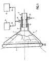
- the respiratory assistance mask 1in accordance with the present invention and shown in Figure 1, has a rigid shell of shape general tapered 2, can be applied to the face 3 of a patient via an inflatable cushion 4, bordering its opening peripheral.
- said mask 1comprises a tubular device 5, fixed or fitted on a tubular projection 6 of said shell 2.
- the tubular device 5serves as an inlet and outlet nozzle for respiratory gas in mask 1.
- itcan be connected to a artificial respiration through its proximal end (opposite to patient 3).
- the device tubular 5has an internal through passage 7 and, in the middle part, a conical wall 8, projecting inside said passage 7.
- the wall conical 8has the purpose of deflecting, in the direction of the axis of the passage 7, jets of respiratory gas injected through peripheral channels 9, supplied from a feed nozzle 10, via a peripheral annular chamber 11.
- the tubular device 5comprises a annular peripheral chamber 12, coaxial with said device 5.
- the chamber annular device 12communicates with the interior of the mask 1 by its distal annular orifice 13 and is provided, at its proximal end, an outlet nozzle 14.
- a filter 15, fibrous or porous (cotton, synthetic foam, etc ...)is arranged in the annular peripheral chamber 12, to dampen gas turbulence and, consequently, excessive variations pressure.
- the outlet nozzle 14can be connected to a gas analyzer 16 and to a device for measuring pressure 17.
- the connections 18 and 19 between the outlet nozzle 14 and the devices 16 and 17are provided so that the removal of gas to be analyzed by the link 18 has no influence on the measurement of pressure, via link 19.
- the practitioner assisting the patient 3constantly knows the composition of the gas in the mask 1 (and in particular its carbon dioxide content) and the pressure inside said mask. He can therefore take appropriate intervention measures depending on said composition and gas pressure.
- the device 5may include channels or conduits for injecting medication and / or water.
- the device 5can find numerous other applications, such as nasal probe, mouth probe, Tracheal tube, etc.
- the dimensions of said deviceare adapted to each particular use.
Landscapes
- Health & Medical Sciences (AREA)
- Life Sciences & Earth Sciences (AREA)
- General Health & Medical Sciences (AREA)
- Engineering & Computer Science (AREA)
- Anesthesiology (AREA)
- Biomedical Technology (AREA)
- Heart & Thoracic Surgery (AREA)
- Hematology (AREA)
- Emergency Medicine (AREA)
- Pulmonology (AREA)
- Public Health (AREA)
- Animal Behavior & Ethology (AREA)
- Veterinary Medicine (AREA)
- Measurement Of The Respiration, Hearing Ability, Form, And Blood Characteristics Of Living Organisms (AREA)
- Respiratory Apparatuses And Protective Means (AREA)
- Massaging Devices (AREA)
- Medicines Containing Material From Animals Or Micro-Organisms (AREA)
- Accommodation For Nursing Or Treatment Tables (AREA)
Abstract
Description
Translated fromFrenchLa présente invention a pour objet un dispositif d'assistance respiratoire,utilisable sur des patients dont la respiration spontanée est absenteou insuffisante, qu'ils soient ou non placés sous respiration artificielle.The present invention relates to a respiratory assistance device,usable on patients whose spontaneous breathing is absentor insufficient, whether or not they are placed on artificial respiration.
Par le brevet européen EP-A-0 390 684 (US-A-5 036 847), onconnaít déjà un dispositif d'assistance respiratoire tubulaire, qui forme uncanal principal et qui est destiné à être relié par son extrémité distale àune voie respiratoire d'un patient pour que ledit canal principal relie à l'extérieurle système respiratoire dudit patient, ledit dispositif comportant aumoins un canal auxiliaire associé à des moyens de déflexion pour injecterun jet de gaz respiratoire défléchi vers l'intérieur dudit canal principal etdestiné à la ventilation dudit patient.By European patent EP-A-0 390 684 (US-A-5 036 847), wealready knows a tubular respiratory assistance device, which forms amain channel and which is intended to be connected by its distal end toa patient's airway so that said main channel connects to the outsidethe respiratory system of said patient, said device comprising atat least one auxiliary channel associated with deflection means for injectinga jet of respiratory gas deflected towards the interior of said main channel andintended for the ventilation of said patient.
La présente invention a pour objet de perfectionner un tel dispositifafin que le praticien puisse connaítre la pression gazeuse et/ou la compositiongazeuse dans ladite voie respiratoire du patient.The object of the present invention is to improve such a deviceso that the practitioner can know the gas pressure and / or the compositiongas in said patient airway.
A cette fin, selon l'invention, le dispositif d'assistance respiratoiredu type rappelé ci-dessus, est remarquable en ce qu'il comporte, du côtédistal, une chambre annulaire, disposée à la périphérie dudit dispositif tubulaire,coaxialement à celui-ci et adaptée pour la communication avec lesystème respiratoire du patient par l'intermédiaire de l'orifice formé par sasection annulaire distale, et en ce que ladite chambre annulaire est pourvuede moyens de liaison avec l'extérieur.To this end, according to the invention, the respiratory assistance deviceof the type recalled above, is remarkable in that it comprises, on the sidedistal, an annular chamber, disposed at the periphery of said tubular device,coaxially with it and adapted for communication with thepatient's respiratory system through the orifice formed by itsdistal annular section, and in that said annular chamber is providedmeans of connection with the outside.
Ainsi, il est possible de mesurer la pression et/ou de déterminer lacomposition du gaz se trouvant dans ladite chambre. On remarquera quece gaz est identique à celui régnant dans le système respiratoire, mais estassagi par rapport à celui-ci, du fait de son isolation partielle par la chambre. Les mesures sont donc fiables, en évitant les conséquences des turbulencesgazeuses.Thus, it is possible to measure the pressure and / or determine thecomposition of the gas in said chamber. We will notice thatthis gas is identical to that prevailing in the respiratory system, but issoftened in relation to it, due to its partial isolation by the room.The measurements are therefore reliable, avoiding the consequences of turbulencesoft.
Notamment à des fins d'homogénéisation du gaz contenu dans lachambre, il est alors préférable que lesdits moyens de liaison avec l'extérieursoient disposés à l'extrémité proximale de ladite chambre.In particular for the purpose of homogenizing the gas contained in theroom, then it is preferable that said means of connection with the outsideare arranged at the proximal end of said chamber.
Dans le cas où les gaz se trouvant dans ladite chambre doiventfaire l'objet d'une analyse de composition et d'une mesure de pression,ladite chambre doit présenter un volume relativement grand, correspondantà la quantité de gaz nécessaire à l'analyse. Il peut alors se produire,dans ladite chambre, des turbulences susceptibles d'induire de fortes variationsdans les mesures de pression.In the event that the gases in the said chamber mustbe subject to a composition analysis and a pressure measurement,said chamber must have a relatively large volume, correspondingthe amount of gas required for the analysis. It can then happen,in said chamber, turbulence capable of inducing large variationsin pressure measurements.
Pour éviter cela, il est avantageux de disposer, dans ladite chambre,des moyens d'amortissement de turbulences gazeuses, tels qu'unfiltre fibreux ou poreux.To avoid this, it is advantageous to have, in said chamber,means for damping gas turbulence, such as afibrous or porous filter.
A titre de sécurité supplémentaire à un éventuel dispositif de mesurede pression, il est avantageux que le dispositif conforme à la présenteinvention comporte un réseau de rainures pratiquées dans la paroidu canal principal et au moins un orifice traversant la partie proximaledudit dispositif, de façon à former une mise à l'air libre du système respiratoiredudit patient, en cas de bouchage accidentel de la partie proximaledudit dispositif.As additional security to any measuring devicepressure, it is advantageous that the device in accordance with thisinvention includes a network of grooves in the wallof the main channel and at least one orifice passing through the proximal partof said device, so as to form a vent to the respiratory systemsaid patient, in the event of accidental blockage of the proximal partof said device.
Le dispositif d'assistance respiratoire tubulaire conforme à la présenteinvention peut trouver de nombreuses applications. Il peut être utilisécomme sonde buccale ou nasale, ou bien encore comme embout rapportéà un tube de trachéotomie. Il peut également, dans un masque respiratoiredestiné à être appliqué sur le visage d'un patient, constituerl'embout tubulaire d'entrée et de sortie du gaz respiratoire. Dans ce cas,ladite chambre est en communication avec le système respiratoire du patientpar l'intermédiaire de l'intérieur dudit masque.The tubular respiratory assistance device in accordance with thisinvention can find many applications. It can be usedas an oral or nasal probe, or even as an added tipto a tracheostomy tube. It can also, in a respiratory maskintended to be applied to the face of a patient, constitutingthe tubular inlet and outlet connector for the respiratory gas. In that case,said chamber is in communication with the patient's respiratory systemthrough the interior of said mask.
Lorsqu'il est utilisé comme embout de masque respiratoire, le dispositifd'assistance respiratoire conforme à la présente invention peut êtresolidaire dudit masque. Cependant, notamment pour pouvoir être utiliséseul, sans masque, il peut être avantageux que ledit dispositif soit montéde façon amovible, par exemple par emboítement, sur ledit masque.When used as a respirator tip, the deviceof respiratory assistance according to the present invention can beintegral with said mask. However, especially to be able to be usedalone, without mask, it may be advantageous for said device to be mountedremovably, for example by fitting, on said mask.
Les figures du dessin annexé feront bien comprendre commentl'invention peut être réalisée. Sur ces figures, des références identiquesdésignent des éléments semblables.
Le masque d'assistance respiratoire 1, conforme à la présente inventionet représenté sur la figure 1, comporte une coque rigide de formegénérale tronconique 2, pouvant être appliquée sur le visage 3 d'un patientpar l'intermédiaire d'un coussinet gonflable 4, bordant son ouverturepériphérique. Du côté opposé, ledit masque 1 comporte un dispositif tubulaire5, fixé ou emboíté sur une saillie tubulaire 6 de ladite coque 2. Ledispositif tubulaire 5 sert d'embout d'entrée et de sortie de gaz respiratoiredans le masque 1. Eventuellement, il peut être relié à un appareil derespiration artificielle par son extrémité proximale (opposée au patient 3).The respiratory assistance mask 1, in accordance with the present inventionand shown in Figure 1, has a rigid shell of shapegeneral tapered 2, can be applied to the
Comme le montrent plus en détail les figures 2 à 5, le dispositiftubulaire 5 comporte un passage traversant interne 7 et, en partie médiane,une paroi conique 8, saillant à l'intérieur dudit passage 7. La paroiconique 8 a pour objet de défléchir, en direction de l'axe du passage 7,des jets de gaz respiratoire injectés par des canaux périphériques 9, alimentésà partir d'un embout d'amenée 10, par l'intermédiaire d'unechambre annulaire périphérique 11.As shown in more detail in Figures 2 to 5, the devicetubular 5 has an internal through
Par ailleurs, du côté distal, le dispositif tubulaire 5 comporte unechambre périphérique annulaire 12, coaxiale audit dispositif 5. La chambrepériphérique annulaire 12 communique avec l'intérieur du masque 1par son orifice annulaire distal 13 et est pourvue, à son extrémité proximale,d'un embout de sortie 14.Furthermore, on the distal side, the
Un filtre 15, fibreux ou poreux (coton, mousse synthétique,etc...) est disposé dans la chambre périphérique annulaire 12, pouramortir les turbulences gazeuses et, par suite, les trop fortes variationsde pression.A
Comme cela est représenté sur la figure 1, l'embout de sortie 14peut être relié à un analyseur de gaz 16 et à un dispositif de mesure depression 17. Bien entendu, les liaisons 18 et 19 entre l'embout de sortie14 et les dispositifs 16 et 17 sont prévues pour que le prélèvement degaz à analyser par la liaison 18 n'ait pas d'influence sur la mesure depression, via la liaison 19.As shown in Figure 1, the
Ainsi, grâce aux dispositifs 16 et 17, le praticien assistant le patient3 connaít en permanence la composition du gaz dans le masque 1(et notamment sa teneur en gaz carbonique) et la pression à l'intérieurdudit masque. Il peut donc prendre les mesures d'intervention appropriéesen fonction desdites composition et pression du gaz.Thus, thanks to the
Dans la variante de réalisation du dispositif 5, montrée par les figures6 à 9, on retrouve les éléments 7 à 15 précédemment décrits en regard des figures 2 à 5. Cependant, on peut remarquer que cette variantede réalisation comporte de plus, dans la paroi du passage 7 et dansla paroi conique 8, des rainures 20, 21, 22 disposées radialement entreles canaux périphériques 9, ainsi qu'au moins un orifice 23 traversant laparoi de l'extrémité proximale du dispositif 5. Ainsi, si pour une raisonquelconque la partie proximale du dispositif 5 est bouchée, les rainures20, 21, 22 et les orifices 23 constituent une mise à l'air libre évitant à lapression du gaz respiratoire injecté d'atteindre des valeurs excessives,susceptibles d'être préjudiciables au patient. On obtient ainsi une sécuritéde fonctionnement automatique, complétant l'éventuel dispositif de mesurede pression 17.In the alternative embodiment of the
Bien que sur les figures, on ne les ait pas respectés, il va de soique le dispositif 5 peut comporter des canaux ou conduits d'injection demédicaments et/ou d'eau.Although in the figures, we did not respect them, it goes without sayingthat the
Par ailleurs, bien que ci-dessus on ait décrit, à l'aide desdites figures,une application particulière du dispositif 5 à un masque respiratoire,on comprendra aisément que ledit dispositif peut trouver de nombreusesautres applications, par exemple comme sonde nasale, sonde buccale,sonde trachéale, etc ... Bien entendu, les dimensions dudit dispositif sontadaptées à chaque utilisation particulière.Furthermore, although above we have described, with the aid of said figures,a particular application of the
Claims (10)
- Tubular respiratory assistance device (5),which forms a main channel (7) and which is intended tobe connected by its distal end to a patient's airway sothat the said main channel (7) connects the saidpatient's respiratory system to the outside, the saiddevice having at least one auxiliary channel (9)associated with deflection means (8) for injecting arespiratory gas jet which is deflected towards theinterior of the said main channel (7) and is intendedto ventilate the said patient,characterized in that ithas, on the distal side, an annular chamber (12)arranged at the periphery of the said tubular device(5), coaxially with it and suitable for communicatingwith the patient's respiratory system by means of theorifice (13) formed by its distal annular section, andin that the said annular chamber (12) is provided withmeans (14) for connection to the outside.
- Respiratory assistance device according toClaim 1,characterized in that the said connectingmeans (14) are arranged at the proximal end of the saidchamber (12).
- Respiratory assistance device according to oneof Claims 1 and 2,characterized in that the gasescontained in the said chamber undergo compositionalanalysis and pressure measurement, andin that means(15) for damping gas turbulence are arranged in thesaid chamber (12).
- Respiratory assistance device according to Claim 3,characterized in that the said means fordamping gas turbulence are formed by a filter of aporous material.
- Respiratory assistance device according toClaim 3,characterized in that the said means fordamping gas turbulence are formed by an annular filterof a fibrous material.
- Respiratory assistance device according to anyone of Claims 1 to 5,characterized in that it has anetwork of grooves (20, 21, 22) made in the wall of thesaid main channel (7) and at least one orifice (23)passing through the proximal part of the said device(5) so as to form an access to the atmosphere for thesaid patient's respiratory system, in the event ofaccidental obstruction of the proximal part of the saiddevice (5).
- Respiratory assistance device according to anyone of Claims 1 to 6,characterized in that itconstitutes the adapter for inlet and outlet ofrespiratory gas of a mask (1) intended to be fitted tothe said patient's face.
- Respiratory assistance device according toClaim 7,characterized in that it is integral with thesaid mask (1).
- Respiratory assistance device according toClaim 7,characterized in it is fitted removably to thesaid mask (1).
- Respiratory assistance device according toClaim 9,characterized in that it can be engaged on thesaid mask (1).
Applications Claiming Priority (2)
| Application Number | Priority Date | Filing Date | Title |
|---|---|---|---|
| FR9713430 | 1997-10-27 | ||
| FR9713430AFR2770137B1 (en) | 1997-10-27 | 1997-10-27 | RESPIRATORY ASSISTANCE DEVICE |
Publications (2)
| Publication Number | Publication Date |
|---|---|
| EP0911051A1 EP0911051A1 (en) | 1999-04-28 |
| EP0911051B1true EP0911051B1 (en) | 2003-06-11 |
Family
ID=9512676
Family Applications (1)
| Application Number | Title | Priority Date | Filing Date |
|---|---|---|---|
| EP98402655AExpired - LifetimeEP0911051B1 (en) | 1997-10-27 | 1998-10-26 | Respiratory assistance device |
Country Status (12)
| Country | Link |
|---|---|
| US (1) | US6273087B1 (en) |
| EP (1) | EP0911051B1 (en) |
| JP (1) | JP4055959B2 (en) |
| CN (1) | CN1182888C (en) |
| AT (1) | ATE242652T1 (en) |
| CA (1) | CA2274021C (en) |
| DE (1) | DE69815464T2 (en) |
| DK (1) | DK0911051T3 (en) |
| ES (1) | ES2201424T3 (en) |
| FR (1) | FR2770137B1 (en) |
| PT (1) | PT911051E (en) |
| WO (1) | WO1999021603A1 (en) |
Families Citing this family (54)
| Publication number | Priority date | Publication date | Assignee | Title |
|---|---|---|---|---|
| FR2782925B1 (en)* | 1998-09-03 | 2000-12-29 | Georges Boussignac | DEVICE FOR BREATHING ASSISTANCE |
| DE29909671U1 (en)* | 1999-06-02 | 1999-09-02 | Dräger Medizintechnik GmbH, 23558 Lübeck | Coupling for a breathing hose system |
| CA2314692C (en)* | 2000-07-28 | 2009-05-19 | Ian Alexander Sloan | Universal respiratory device coupler |
| FR2831824B1 (en)* | 2001-11-06 | 2004-01-23 | Georges Boussignac | DEVICE FOR RESPIRATORY ASSISTANCE |
| FR2836384B1 (en)* | 2002-02-27 | 2004-12-10 | Georges Boussignac | RESPIRATORY ASSISTANCE DEVICE |
| AU2003245018A1 (en)* | 2002-07-22 | 2004-02-09 | Hasdi Matarasso | A respiratory aid apparatus and method |
| US20040089305A1 (en)* | 2002-11-13 | 2004-05-13 | Vallarta John-Eric S. | Endotracheal tube safety device connector |
| US7749169B2 (en)* | 2003-04-10 | 2010-07-06 | Intoximeters, Inc. | Handheld breath tester housing and mouthpiece |
| US20060180149A1 (en)* | 2003-07-22 | 2006-08-17 | Hasdi Matarasso | A respiratory aid system and method |
| US8336549B2 (en)* | 2003-12-29 | 2012-12-25 | Ramses Nashed | Disposable anesthesia face mask |
| DE102004030070B3 (en)* | 2004-06-23 | 2005-12-08 | Drägerwerk AG | Respiratory mask with individual adaptation to the face shape |
| FR2873042B1 (en)* | 2004-07-19 | 2007-12-14 | Fabrice Ghiron | OXYGEN MASK TOOL, OXYGEN MASK AND CORRESPONDING RESPIRATORY MONITORING ASSEMBLY |
| US8042539B2 (en)* | 2004-12-10 | 2011-10-25 | Respcare, Inc. | Hybrid ventilation mask with nasal interface and method for configuring such a mask |
| US20060217625A1 (en)* | 2005-03-25 | 2006-09-28 | Forrester Macquorn R Jr | Mouthpiece for breath tester |
| US20070113852A1 (en)* | 2005-11-18 | 2007-05-24 | Christopher Martin | Snap-in deflector for respiratory mask |
| US7578294B2 (en) | 2005-12-02 | 2009-08-25 | Allegiance Corporation | Nasal continuous positive airway pressure device and system |
| FR2899483B1 (en)* | 2006-04-06 | 2008-05-30 | Georges Boussignac | ARTIFICIAL BREATHING DEVICE FOR PATIENTS WITH HYPOXEMIA OR ANOXEMIA |
| FR2911073B1 (en)* | 2007-01-08 | 2009-02-20 | Georges Boussignac | ARTIFICIAL BREATHING DEVICE FOR EMERGENCY RELIEF. |
| FR2912660B1 (en)* | 2007-02-15 | 2009-11-27 | Georges Boussignac | ARTIFICIAL RESPIRATION DEVICE FOR A PERSON IN CARDIAC ARREST STATUS. |
| JP4998878B2 (en)* | 2007-02-16 | 2012-08-15 | 日本光電工業株式会社 | Carbon dioxide gas measurement nose mask |
| US8851072B2 (en)* | 2007-02-16 | 2014-10-07 | Wasatch Manufacturing, Llc | Supplemental air diffusion devices, kits and methods |
| US8826905B2 (en)* | 2007-06-01 | 2014-09-09 | Ramses Nashed | Respiratory face mask and breathing circuit assembly |
| FR2920001B1 (en)* | 2007-08-17 | 2010-09-24 | Jacek Wasylkiewicz | HIGH CONCENTRATION OXYGEN MASK TOOL, HIGH CONCENTRATION OXYGEN MASK AND CORRESPONDING RESPIRATORY MONITORING ASSEMBLY |
| US8251876B2 (en) | 2008-04-22 | 2012-08-28 | Hill-Rom Services, Inc. | Breathing exercise apparatus |
| CN102196837B (en) | 2008-08-22 | 2015-09-09 | 呼吸科技公司 | Methods and devices for providing mechanical ventilation utilizing an open airway interface |
| EP2186539B1 (en) | 2008-11-17 | 2014-06-18 | Jacek Wasylkiewicz | Specific nozzle for a High-Concentration Oxygen mask. |
| US8893716B2 (en)* | 2009-10-20 | 2014-11-25 | Mercury Enterprises, Inc. | Disposable breathing assistance device with manometer |
| US10086166B1 (en) | 2010-02-01 | 2018-10-02 | Sedation Systems, Llc | Demand gas flow valve apparatus |
| US8726900B1 (en)* | 2010-02-01 | 2014-05-20 | Ramses Nashed | Demand anesthetic gas delivery system with disposable breathing and scavenging circuit |
| GB201006480D0 (en)* | 2010-04-19 | 2010-06-02 | Intersurgical Ag | Improvements relating to respiratory apparatus |
| US10265492B2 (en)* | 2010-04-30 | 2019-04-23 | Resmed Limited | Respiratory mask |
| FR2971162B1 (en)* | 2011-02-03 | 2013-11-22 | Georges Boussignac | ARTIFICIAL BREATHING DEVICE FOR THE RESUSCITATION OF A PERSON WITH A CARDIAC ARREST |
| US9180271B2 (en) | 2012-03-05 | 2015-11-10 | Hill-Rom Services Pte. Ltd. | Respiratory therapy device having standard and oscillatory PEP with nebulizer |
| US9713687B2 (en)* | 2012-08-21 | 2017-07-25 | Philip Morris Usa Inc. | Ventilator aerosol delivery system with transition adapter for introducing carrier gas |
| US9370635B2 (en) | 2012-08-23 | 2016-06-21 | Mercury Enterprises, Inc. | Optimized breathing assistance device |
| FR2994852B1 (en)* | 2012-08-28 | 2015-09-04 | Georges Boussignac | RESPIRATORY ASSISTANCE DEVICE, NASAL APPARATUS AND RESPIRATORY ASSISTANCE MASK |
| WO2014041472A1 (en) | 2012-09-14 | 2014-03-20 | Fisher & Paykel Healthcare Limited | External sensor arrangement for patient interface |
| GB2506621B (en)* | 2012-10-03 | 2018-08-08 | Intersurgical Ag | Respiratory mask |
| WO2014109749A1 (en)* | 2013-01-10 | 2014-07-17 | Rollins Offord L | Multi-function oxygen mask |
| WO2014129912A1 (en) | 2013-02-20 | 2014-08-28 | Fisher & Paykel Healthcare Limited | Connector for multiple sized connections |
| EP3892319B1 (en) | 2013-02-21 | 2022-12-28 | Fisher & Paykel Healthcare Limited | Patient interface with venting |
| CN203749974U (en)* | 2013-09-07 | 2014-08-06 | 王家松 | Simple multifunctional intubation guide and protection device |
| FR3022146A1 (en)* | 2014-06-13 | 2015-12-18 | Vygon | RESPIRATORY ASSISTANCE DEVICE, NASAL APPARATUS AND RESPIRATORY ASSISTANCE MASK |
| US11602607B2 (en) | 2014-09-24 | 2023-03-14 | Fisher & Paykel Healthcare Limited | Swivel connector |
| FR3028766A1 (en)* | 2014-11-24 | 2016-05-27 | Georges Boussignac | DEVICE FOR VISUALIZING THE OPERATION OF A RESPIRATORY ASSISTANCE DEVICE, AN ASSEMBLY WITH A BONDING SYSTEM AND A METHOD OF USE |
| EP4186548A1 (en) | 2015-04-02 | 2023-05-31 | Hill-Rom Services PTE. LTD. | Mask leakage detection for a respiratory device |
| WO2017177340A1 (en) | 2016-04-14 | 2017-10-19 | Vo2 Master Health Sensors Inc. | Device for measuring a user's oxygen-consumption |
| FR3050381B1 (en)* | 2016-04-22 | 2018-04-20 | Georges Boussignac | CATHETER OF MIXED MEASUREMENTS FOR RESPIRATORY INTUBATION PROBE |
| CN105963838B (en)* | 2016-06-08 | 2018-12-14 | 湖南明康中锦医疗科技发展有限公司 | A kind of empty oxygen mixed structure and ventilator for ventilator |
| TWI678198B (en) | 2017-11-28 | 2019-12-01 | 財團法人工業技術研究院 | Adjustable respirator shell |
| EP3764899A4 (en) | 2018-03-15 | 2021-12-15 | Vo2 Master Health Sensors Inc. | Device for measuring a person's ventilation including oxygen-consumption |
| US11696996B2 (en)* | 2018-06-27 | 2023-07-11 | Hu-Friedy Mfg. Co., Llc | Capnography tube fitting |
| DE102019003395A1 (en) | 2019-05-14 | 2020-11-19 | Drägerwerk AG & Co. KGaA | Connection arrangement for establishing a fluid connection between a medical device and a patient-side coupling unit |
| KR20230034286A (en)* | 2020-07-02 | 2023-03-09 | 필립모리스 프로덕츠 에스.에이. | Test Chamber Apparatus for Evaluating Filter Media |
Family Cites Families (22)
| Publication number | Priority date | Publication date | Assignee | Title |
|---|---|---|---|---|
| US3661528A (en) | 1970-04-02 | 1972-05-09 | Instrumentation Associates Inc | Breath sampler |
| FR2174782B1 (en)* | 1972-03-10 | 1975-03-21 | Lafourcade Jean Michel | |
| US4207884A (en)* | 1976-12-20 | 1980-06-17 | Max Isaacson | Pressure controlled breathing apparatus |
| US4592349A (en)* | 1981-08-10 | 1986-06-03 | Bird F M | Ventilator having an oscillatory inspiratory phase and method |
| US4558708A (en)* | 1984-10-24 | 1985-12-17 | Tri-Med, Inc. | Patient's airway adapter to withdraw a patient's gas samples for testing free of sputum mucus and/or condensed water, by utilizing a hollow cylindrical hydrophobic liquid baffle |
| IL76939A (en)* | 1984-11-13 | 1990-01-18 | Andros Analyzers Inc | Adaptor assembly for airway tube |
| US5166075A (en)* | 1986-08-13 | 1992-11-24 | Nellcor Incorporated | Method for determining whether respiratory gas is present in a gaseous sample |
| US4852583A (en)* | 1987-01-16 | 1989-08-01 | Spacelabs, Inc. | Airway adapter |
| US5335656A (en)* | 1988-04-15 | 1994-08-09 | Salter Laboratories | Method and apparatus for inhalation of treating gas and sampling of exhaled gas for quantitative analysis |
| FR2645026B1 (en) | 1989-03-31 | 1997-11-21 | Boussignac Georges | RESPIRATORY ASSISTANCE DEVICE |
| DE9202198U1 (en)* | 1992-02-20 | 1992-06-11 | Klein, Christoph, 5205 St Augustin | Medical device for inhalation of metered dose aerosols |
| GB9212399D0 (en)* | 1992-06-11 | 1992-07-22 | Pall Corp | Heat and moisture exchanging filters |
| US5474060A (en)* | 1993-08-23 | 1995-12-12 | Evans; David | Face mask with gas sampling port |
| FR2709251B1 (en)* | 1993-08-26 | 1995-11-10 | Georges Boussignac | Breathing assistance tube. |
| US5465728A (en)* | 1994-01-11 | 1995-11-14 | Phillips; Michael | Breath collection |
| FR2724564B1 (en)* | 1994-09-16 | 1997-04-04 | Boussignac Georges | RESPIRATORY ASSISTANCE DEVICE |
| US5642726A (en)* | 1994-10-18 | 1997-07-01 | Alcove Medical, Inc. | Reduced internal volume neonatal suction adaptor |
| US6129680A (en)* | 1995-06-19 | 2000-10-10 | Btg International Limited | Animal exhalation monitoring |
| IL114964A (en)* | 1995-08-16 | 2000-10-31 | Versamed Medical Systems Ltd | Computer controlled portable ventilator |
| US5789660A (en)* | 1996-07-15 | 1998-08-04 | Novametrix Medical Systems, Inc. | Multiple function airway adapter |
| US5829429A (en)* | 1997-04-21 | 1998-11-03 | Hughes; Arthur R. | Acoustic respiratory therapy apparatus |
| US5979444A (en)* | 1997-06-17 | 1999-11-09 | Sherrod; James B. | Portable CPR breathing apparatus |
- 1997
- 1997-10-27FRFR9713430Apatent/FR2770137B1/ennot_activeExpired - Lifetime
- 1998
- 1998-10-26ESES98402655Tpatent/ES2201424T3/ennot_activeExpired - Lifetime
- 1998-10-26DEDE69815464Tpatent/DE69815464T2/ennot_activeExpired - Lifetime
- 1998-10-26CNCNB988016044Apatent/CN1182888C/ennot_activeExpired - Fee Related
- 1998-10-26USUS09/319,307patent/US6273087B1/ennot_activeExpired - Lifetime
- 1998-10-26PTPT98402655Tpatent/PT911051E/enunknown
- 1998-10-26WOPCT/FR1998/002280patent/WO1999021603A1/enactiveApplication Filing
- 1998-10-26CACA002274021Apatent/CA2274021C/ennot_activeExpired - Lifetime
- 1998-10-26DKDK98402655Tpatent/DK0911051T3/enactive
- 1998-10-26JPJP52339999Apatent/JP4055959B2/ennot_activeExpired - Lifetime
- 1998-10-26ATAT98402655Tpatent/ATE242652T1/enactive
- 1998-10-26EPEP98402655Apatent/EP0911051B1/ennot_activeExpired - Lifetime
Also Published As
| Publication number | Publication date |
|---|---|
| CA2274021C (en) | 2008-01-08 |
| DK0911051T3 (en) | 2003-07-21 |
| EP0911051A1 (en) | 1999-04-28 |
| DE69815464T2 (en) | 2004-05-13 |
| JP4055959B2 (en) | 2008-03-05 |
| PT911051E (en) | 2003-09-30 |
| JP2001507270A (en) | 2001-06-05 |
| US6273087B1 (en) | 2001-08-14 |
| CN1182888C (en) | 2005-01-05 |
| DE69815464D1 (en) | 2003-07-17 |
| ES2201424T3 (en) | 2004-03-16 |
| FR2770137A1 (en) | 1999-04-30 |
| CA2274021A1 (en) | 1999-05-06 |
| CN1242711A (en) | 2000-01-26 |
| ATE242652T1 (en) | 2003-06-15 |
| FR2770137B1 (en) | 2000-01-28 |
| WO1999021603A1 (en) | 1999-05-06 |
Similar Documents
| Publication | Publication Date | Title |
|---|---|---|
| EP0911051B1 (en) | Respiratory assistance device | |
| CA2030546C (en) | Apparatus for assisted ventilation | |
| CA2695570C (en) | Breathing assistance device | |
| EP2001540B1 (en) | Artificial respiration device for patients suffering from hypoxemia or anoxemia | |
| EP0888792B1 (en) | Suction endotracheal tube for use in a patient under artificial ventilation | |
| EP0978291B1 (en) | Respiratory assistance device | |
| EP1340515B1 (en) | Device for breathing assistance | |
| EP0701834B1 (en) | Respiratory assistance device | |
| EP0245142B1 (en) | Tube for respiratory assistance | |
| EP0983772B1 (en) | Respiratory assistance device | |
| WO2003039638A1 (en) | Respiratory assistance device | |
| EP2239004B1 (en) | Respiratory aid device and measurement system comprising such a device | |
| EP0451062A1 (en) | Nasal mucus withdrawing device | |
| FR2921840A1 (en) | Tubular respiratory assistance device for e.g. child in hospital, has sealing unit surrounding distal end of device and assuring sealed gaseous communication, at throat of patient, between trachea of patient and main channel | |
| FR2942967A1 (en) | RESPIRATORY ASSISTANCE DEVICE | |
| FR2994852A1 (en) | RESPIRATORY ASSISTANCE DEVICE, NASAL APPARATUS AND RESPIRATORY ASSISTANCE MASK | |
| FR2597754A1 (en) | Tube for respiratory assistance | |
| CA2130880C (en) | Assisted ventilation tube | |
| FR2936955A1 (en) | Artificial respiration device for resuscitation of patient in cardiac arrest state, has auxiliary tubular connector including isolating unit e.g. individual obturator, that isolates proximal ends of longitudinal channels from open air | |
| WO1994000175A1 (en) | Endotracheal tube |
Legal Events
| Date | Code | Title | Description |
|---|---|---|---|
| PUAI | Public reference made under article 153(3) epc to a published international application that has entered the european phase | Free format text:ORIGINAL CODE: 0009012 | |
| AK | Designated contracting states | Kind code of ref document:A1 Designated state(s):AT BE CH DE DK ES FI GB GR IE IT LI LU MC NL PT SE | |
| AX | Request for extension of the european patent | Free format text:AL;LT;LV;MK;RO;SI | |
| 17P | Request for examination filed | Effective date:19990602 | |
| RAP1 | Party data changed (applicant data changed or rights of an application transferred) | Owner name:LABRUNE, JEAN-CLAUDE Owner name:BOUSSIGNAC, GEORGES | |
| RIN1 | Information on inventor provided before grant (corrected) | Inventor name:LABRUNE, JEAN-CLAUDE Inventor name:BOUSSIGNAC, GEORGES | |
| K1C1 | Correction of patent application (title page) published | Effective date:19990428 | |
| AKX | Designation fees paid | Free format text:AT BE CH DE DK ES FI GB GR IE IT LI LU MC NL PT SE | |
| 17Q | First examination report despatched | Effective date:20020628 | |
| GRAH | Despatch of communication of intention to grant a patent | Free format text:ORIGINAL CODE: EPIDOS IGRA | |
| GRAH | Despatch of communication of intention to grant a patent | Free format text:ORIGINAL CODE: EPIDOS IGRA | |
| GRAA | (expected) grant | Free format text:ORIGINAL CODE: 0009210 | |
| AK | Designated contracting states | Designated state(s):AT BE CH DE DK ES FI GB GR IE IT LI LU MC NL PT SE | |
| PG25 | Lapsed in a contracting state [announced via postgrant information from national office to epo] | Ref country code:FI Free format text:LAPSE BECAUSE OF FAILURE TO SUBMIT A TRANSLATION OF THE DESCRIPTION OR TO PAY THE FEE WITHIN THE PRESCRIBED TIME-LIMIT Effective date:20030611 | |
| REG | Reference to a national code | Ref country code:GB Ref legal event code:FG4D Free format text:NOT ENGLISH | |
| REG | Reference to a national code | Ref country code:CH Ref legal event code:NV Representative=s name:CRONIN INTELLECTUAL PROPERTY Ref country code:CH Ref legal event code:EP | |
| GBT | Gb: translation of ep patent filed (gb section 77(6)(a)/1977) | ||
| REG | Reference to a national code | Ref country code:IE Ref legal event code:FG4D Free format text:FRENCH | |
| REF | Corresponds to: | Ref document number:69815464 Country of ref document:DE Date of ref document:20030717 Kind code of ref document:P | |
| REG | Reference to a national code | Ref country code:DK Ref legal event code:T3 | |
| PG25 | Lapsed in a contracting state [announced via postgrant information from national office to epo] | Ref country code:GR Free format text:LAPSE BECAUSE OF FAILURE TO SUBMIT A TRANSLATION OF THE DESCRIPTION OR TO PAY THE FEE WITHIN THE PRESCRIBED TIME-LIMIT Effective date:20030911 | |
| REG | Reference to a national code | Ref country code:SE Ref legal event code:TRGR | |
| REG | Reference to a national code | Ref country code:PT Ref legal event code:SC4A Free format text:AVAILABILITY OF NATIONAL TRANSLATION Effective date:20030812 | |
| PG25 | Lapsed in a contracting state [announced via postgrant information from national office to epo] | Ref country code:MC Free format text:LAPSE BECAUSE OF NON-PAYMENT OF DUE FEES Effective date:20031031 | |
| REG | Reference to a national code | Ref country code:ES Ref legal event code:FG2A Ref document number:2201424 Country of ref document:ES Kind code of ref document:T3 | |
| PLBE | No opposition filed within time limit | Free format text:ORIGINAL CODE: 0009261 | |
| STAA | Information on the status of an ep patent application or granted ep patent | Free format text:STATUS: NO OPPOSITION FILED WITHIN TIME LIMIT | |
| 26N | No opposition filed | Effective date:20040312 | |
| REG | Reference to a national code | Ref country code:CH Ref legal event code:PCAR Free format text:CRONIN INTELLECTUAL PROPERTY;CHEMIN DE PRECOSSY 31;1260 NYON (CH) | |
| PGFP | Annual fee paid to national office [announced via postgrant information from national office to epo] | Ref country code:AT Payment date:20100917 Year of fee payment:13 | |
| PGFP | Annual fee paid to national office [announced via postgrant information from national office to epo] | Ref country code:LU Payment date:20110926 Year of fee payment:14 | |
| REG | Reference to a national code | Ref country code:AT Ref legal event code:MM01 Ref document number:242652 Country of ref document:AT Kind code of ref document:T Effective date:20121026 | |
| PG25 | Lapsed in a contracting state [announced via postgrant information from national office to epo] | Ref country code:AT Free format text:LAPSE BECAUSE OF NON-PAYMENT OF DUE FEES Effective date:20121026 | |
| PG25 | Lapsed in a contracting state [announced via postgrant information from national office to epo] | Ref country code:LU Free format text:LAPSE BECAUSE OF NON-PAYMENT OF DUE FEES Effective date:20121026 | |
| PGFP | Annual fee paid to national office [announced via postgrant information from national office to epo] | Ref country code:CH Payment date:20170908 Year of fee payment:20 Ref country code:GB Payment date:20170801 Year of fee payment:20 | |
| PGFP | Annual fee paid to national office [announced via postgrant information from national office to epo] | Ref country code:IE Payment date:20170721 Year of fee payment:20 Ref country code:BE Payment date:20170721 Year of fee payment:20 Ref country code:DK Payment date:20170727 Year of fee payment:20 Ref country code:SE Payment date:20170727 Year of fee payment:20 | |
| PGFP | Annual fee paid to national office [announced via postgrant information from national office to epo] | Ref country code:DE Payment date:20170725 Year of fee payment:20 | |
| PGFP | Annual fee paid to national office [announced via postgrant information from national office to epo] | Ref country code:PT Payment date:20171023 Year of fee payment:20 Ref country code:ES Payment date:20171107 Year of fee payment:20 Ref country code:IT Payment date:20171005 Year of fee payment:20 Ref country code:NL Payment date:20171019 Year of fee payment:20 | |
| REG | Reference to a national code | Ref country code:CH Ref legal event code:PCAR Free format text:NEW ADDRESS: CHEMIN DE LA VUARPILLIERE 29, 1260 NYON (CH) | |
| REG | Reference to a national code | Ref country code:DE Ref legal event code:R071 Ref document number:69815464 Country of ref document:DE | |
| REG | Reference to a national code | Ref country code:CH Ref legal event code:PL Ref country code:NL Ref legal event code:MK Effective date:20181025 | |
| REG | Reference to a national code | Ref country code:DK Ref legal event code:EUP Effective date:20181026 | |
| REG | Reference to a national code | Ref country code:GB Ref legal event code:PE20 Expiry date:20181025 | |
| REG | Reference to a national code | Ref country code:IE Ref legal event code:MK9A | |
| REG | Reference to a national code | Ref country code:SE Ref legal event code:EUG | |
| REG | Reference to a national code | Ref country code:BE Ref legal event code:MK Effective date:20181026 | |
| PG25 | Lapsed in a contracting state [announced via postgrant information from national office to epo] | Ref country code:PT Free format text:LAPSE BECAUSE OF EXPIRATION OF PROTECTION Effective date:20181106 Ref country code:IE Free format text:LAPSE BECAUSE OF EXPIRATION OF PROTECTION Effective date:20181026 | |
| PG25 | Lapsed in a contracting state [announced via postgrant information from national office to epo] | Ref country code:GB Free format text:LAPSE BECAUSE OF EXPIRATION OF PROTECTION Effective date:20181025 | |
| REG | Reference to a national code | Ref country code:ES Ref legal event code:FD2A Effective date:20200721 | |
| PG25 | Lapsed in a contracting state [announced via postgrant information from national office to epo] | Ref country code:ES Free format text:LAPSE BECAUSE OF EXPIRATION OF PROTECTION Effective date:20181027 |