EP0908850A1 - A method of shape modification for CAD systems - Google Patents
A method of shape modification for CAD systemsDownload PDFInfo
- Publication number
- EP0908850A1 EP0908850A1EP98402471AEP98402471AEP0908850A1EP 0908850 A1EP0908850 A1EP 0908850A1EP 98402471 AEP98402471 AEP 98402471AEP 98402471 AEP98402471 AEP 98402471AEP 0908850 A1EP0908850 A1EP 0908850A1
- Authority
- EP
- European Patent Office
- Prior art keywords
- zone
- deformation
- constraints
- area
- internal
- Prior art date
- Legal status (The legal status is an assumption and is not a legal conclusion. Google has not performed a legal analysis and makes no representation as to the accuracy of the status listed.)
- Granted
Links
Images


Classifications
- G—PHYSICS
- G06—COMPUTING OR CALCULATING; COUNTING
- G06T—IMAGE DATA PROCESSING OR GENERATION, IN GENERAL
- G06T17/00—Three dimensional [3D] modelling, e.g. data description of 3D objects
- G06T17/30—Polynomial surface description
Definitions
- the subject of the present inventionis a method of modification shaped, intended to allow the user of a computer-aided design system to modify a surface shape and to provide the user with a representation of the modified form.
- EP-A-0 576 218describes a method for solving this problem.
- this processis limited to obtaining a continuity which does not exceed G 1 at the borders.
- a partial differential equationis generated which represents the surface as a physical membrane. The process is not used to modify a pre-existing shape and does not allow for higher order continuity at the borders.
- the inventionaims to provide a method of modifying an existing zone while respecting a continuity G k (k being at least equal to -1) at the borders and respecting internal constraints.
- a continuity G 0is a simple passage constraint.
- a continuity of order 1is a constraint of continuity of tangent plane.
- a continuity of order 2respects the normal curvatures in all directions at a point or along a curve. Higher values of k and n are possible and have no simple geometric counterpart. Sometimes a tear must be obtained between the modified area and the rest of the surface. This is designated as G -1 continuity.
- a continuity G 0 + G 1 along one side of the borderrequires that the "generalized" plate representing the deformation remains flat along this side after deformation.
- An external constraint G 0 at the bordercan be viewed, by analogy with mechanical considerations, as the requirement that there is a determined distribution of forces along the border. In the case of constraints of order G 1 'the analogy with a plate returns to the application, along the border, of moments having a determined distribution, adding to the distribution of the forces. On the other hand, there is no analogy in terms of material deformation beyond a G 1 constraint. But it has been found that the increase in k results in a deeper modified form, which has greater slopes.
- Precisionwill be high at certain points on the border where we will impose a coincidence, but in no other point of the border it should not be less than a value predetermined. To respect this last condition, we may increase, if necessary, the points located on the border where the continuity criterion is met so rigorous, to the nearest quantification, until the degree precision required be respected for all points intermediaries.
- the minimization calculationmust be done while respecting also the continuity constraints along each of the sides of the area to be deformed. Borders can be closed or through.
- E ( ⁇ )defines the linear energy of elastic bending of an infinite horizontal thin plate, having a zero Poisson's ratio, whose displacement field vertical is ⁇ .
- the inventionalso aims to provide a method for filling a hole in a surface or for generating a connection zone while respecting external constraints G k , k being at least equal to 2, and internal constraints G n , n being at less than zero.
- the process described in document EP-A-0 576 218is only capable of respecting external constraints G 0 or G 1 .
- Figures 1A and 1Bshow an example of application of the invention.
- Zone 10 of Figure 1Adelimited by five curvilinear sides and having as many vertices, must be deformed to bring it to point A, respecting a continuity G 1 (indicated by the double arrows). This means that the planes tangent to the original "surface” along the border must remain planes tangent to both the deformed area and the rest of the original "surface” ( Figure 1B).
- the contours defining the area to be modifiedare projected parallel to d on a perpendicular plane ⁇ . They constitute a plane domain D ⁇ (X, Y) on which we can define the law of deformation d (X, Y). In this case, d corresponds to ⁇ in formula (1) .
- the planar coordinates X and Ycorrespond to coordinates (u, v) of the initial shape of the area to be deformed. In general, the curvilinear sides of the area will be defined in approximate form by parametric polynomial (or rational) equations, chosen to ensure the required precision.
- the modified final formwill be obtained by gluing ⁇ F D ⁇ and the restriction (F ⁇ F D ⁇ ).
- equation (1)becomes:
- An internal constraintis introduced for example using human-computer interaction devices such as a mouse, a so-called “track ball” or any other handful of manipulation on a screen.
- the internal stresscan be the fact that the deformed zone passes by a point ⁇ F D ⁇ (u 0 , v 0 ) where the direction of the initial tangent plane is preserved.
- deformation d (X, Y)is that of an initially planar and infinite plate, and not that of a plate having the original shape, in mathematical analogy.
- FIG. 3an example has been shown. distribution of forces corresponding to a deformation particular, with a constraint of passage along the sides of the domain.
- the approachwhich will determine the shape while respecting external (edge constraints) and internal constraints (for example passing through a specific location) will constituted by the search for the deformation corresponding to the minimum of the energy E ( ⁇ ) given by the formula (1).
- This approachcan constitute an extrapolation and an adaptation from that described in the article "An Aesthetic Preserving Algorithm for Accuracy Incompatible Modelers Data Exchange " by G. Durand, A. Leutier and A. Massabo, IDMME, 1996.
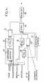
- Figure 4shows the functions to perform in setting of the process. Some of these functions are simply optional and most are already carried out by software modules available.
- a first software module 12can be provided to verify consistency between at least the form sought, the direction deformation d, and the contours to be respected. In some case indeed, a deformation in the direction of only may not allow internal constraints to be met imposed on the model.
- the shapeis processed by a module 14 which gives a projection parallel to the direction d (on the plane ⁇ in Figure 2).
- the projection on the plane ⁇ of the contours, according to the direction d,is also determined by a module 16.
- Another module 18calculates the projection of the shape on the plane ⁇ .
- the deformations d (X, Y)are calculated by a module 20 which applies an algorithm of the "elastic infinite thin plate” type, mentioned above, respecting the constraints relative. This algorithm is applied in the plane ⁇ , that is to say from a flat shape, not in space 3D; the deformations thus obtained are applied to the original "surface” in the selected area.
- the parameters enteredinclude indications of precision, taking into account continuity initial internal form to modify.
Landscapes
- Physics & Mathematics (AREA)
- Engineering & Computer Science (AREA)
- General Physics & Mathematics (AREA)
- Pure & Applied Mathematics (AREA)
- Mathematical Optimization (AREA)
- Mathematical Physics (AREA)
- Mathematical Analysis (AREA)
- Algebra (AREA)
- Computer Graphics (AREA)
- Geometry (AREA)
- Software Systems (AREA)
- Theoretical Computer Science (AREA)
- Processing Or Creating Images (AREA)
Abstract
Description
Translated fromFrenchLa présente invention a pour objet un procédé de modificationde forme, destiné à permettre à l'utilisateur d'unsystème de conception assistée par ordinateur de modifier uneforme surfacique et à fournir à l'utilisateur une représentationde la forme modifiée.The subject of the present invention is a method of modificationshaped, intended to allow the user of acomputer-aided design system to modify asurface shape and to provide the user with a representationof the modified form.
On utilisera souvent par la suite le terme "surface". Ilest à interpréter de façon générale, comme désignant nonseulement une surface proprement dite, mais aussi une formesurfacique définie par morceaux Gk-continus ou une peau devolume ; k est un entier positif ou nul ; il peut même y avoirdes arrachements, pour lesquels k=-1.The term "surface" will often be used later. It is to be interpreted generally, as designating not only a surface proper, but also a surface shape defined by pieces Gk -continuous or a skin of volume; k is a positive or zero integer; there may even be tears, for which k = -1.
Pour des raisons constructives ou de style, on peutsouhaiter modifier une zone ou la totalité d'une "surface"d'origine, définie par sa topologie, de façon à faire passerla nouvelle forme par un emplacement indiqué par un opérateur(ligne ou points déterminés) et cela en respectant ou non unecontinuité de plan tangent ou de courbure. Ces exigencesconstituent des contraintes internes. Les modificationsdoivent de plus satisfaire des contraintes externes, qui sont,avec une tolérance déterminée, la continuité entre la forme dela zone modifiée et le reste de la "surface" d'origine.For constructive or stylistic reasons, we canwish to modify an area or all of a "surface"origin, defined by its topology, so as to passthe new shape by a location indicated by an operator(line or points determined) and this respecting or not acontinuity of tangent plane or curvature. These requirementsare internal constraints. Modificationsmust also satisfy external constraints, which are,with a determined tolerance, the continuity between the form ofthe modified area and the rest of the original "surface".
Un autre problème qui peut apparaítre pour des raisonsconstructives de style est la génération d'une représentationd'une surface courbe remplissant une zone déterminée, en respectant des contraintes externes le long des frontières dela zone et des contraintes internes. Le document EP-A-0576 218 décrit un procédé pour résoudre ce problème. Mais ceprocédé est limité à l'obtention d'une continuité qui nedépasse pas G1 aux frontières. Suivant ce procédé antérieur,on génère une équation aux dérivées partielles qui représentela surface comme une membrane physique. Le procédé n'est pasutilisé pour modifier une forme pré-existante et ne permet pasd'arriver à une continuité d'ordre plus élevé aux frontières.Another problem that may arise for constructive style reasons is the generation of a representation of a curved surface filling a determined area, respecting external constraints along the boundaries of the area and internal constraints. EP-A-0 576 218 describes a method for solving this problem. However, this process is limited to obtaining a continuity which does not exceed G1 at the borders. According to this prior process, a partial differential equation is generated which represents the surface as a physical membrane. The process is not used to modify a pre-existing shape and does not allow for higher order continuity at the borders.
L'invention, suivant un premier aspect, vise à fournir unprocédé de modification d'une zone existante en respectant unecontinuité Gk (k étant au moins égal à -1) aux frontières etrespectant des contraintes internes.The invention, according to a first aspect, aims to provide a method of modifying an existing zone while respecting a continuity Gk (k being at least equal to -1) at the borders and respecting internal constraints.
Dans ce but, l'invention propose notamment un procédé demodification de forme permettant de générer un modèle surfaciquepar déformation (et non pas par génération) d'une zoneou d'une "surface" d'origine, suivant lequel :
Une continuité G0 est une simple contrainte de passage. Unecontinuité d'ordre 1 est une contrainte de continuité de plantangent. Une continuité d'ordre 2 respecte les courburesnormales dans toutes les directions en un point ou suivant unecourbe. Des valeurs supérieures de k et de n sont possibles etn'ont pas de contrepartie géométrique simple. Quelquefois unedéchirure doit être obtenue entre la zone modifiée et le restede la surface. Cela est désigné comme une continuité G-1.A continuity G0 is a simple passage constraint. A continuity of order 1 is a constraint of continuity of tangent plane. A continuity of order 2 respects the normal curvatures in all directions at a point or along a curve. Higher values of k and n are possible and have no simple geometric counterpart. Sometimes a tear must be obtained between the modified area and the rest of the surface. This is designated as G-1 continuity.
Le terme "généralisé" est à interpréter comme désignant uncomportement pouvant aller, du point de vue de la mécanique,au-delà de celui d'une plaque mince réelle soumise à desactions mécaniques (forces ou moments) tendant à la déformer.La généralisation se fait sur les actions mécaniques et surl'expression de "l'énergie" à minimiser. Au-delà de G2, ils'agit d'ultra-réalité.The term "generalized" is to be interpreted as designating a behavior which can go, from the point of view of mechanics, beyond that of a real thin plate subjected to mechanical actions (forces or moments) tending to deform it. Generalization is done on mechanical actions and on the expression of "energy" to minimize. Beyond G2 , it is about ultra-reality.
Une continuité G0+G1 le long d'un côté de la frontièreexige que la plaque "généralisée" représentant la déformationreste plane le long de ce côté après déformation. Une contrainteexterne G0 à la frontière peut être regardée, paranalogie avec des considérations mécaniques, comme l'exigencequ'il y ait une distribution déterminée de forces le long de la frontière. Dans le cas de contraintes d'ordre G1' l'analogieavec une plaque revient à l'application, le long de lafrontière, de moments ayant une distribution déterminée,s'ajoutant à la distribution des forces. En revanche, il n'ya pas d'analogie en matière de déformation des matériaux au-delàd'une contrainte G1. Mais on a constaté que l'augmentationde k résulte dans une forme modifiée plus profonde, quiprésente des pentes plus importantes.A continuity G0 + G1 along one side of the border requires that the "generalized" plate representing the deformation remains flat along this side after deformation. An external constraint G0 at the border can be viewed, by analogy with mechanical considerations, as the requirement that there is a determined distribution of forces along the border. In the case of constraints of order G1 'the analogy with a plate returns to the application, along the border, of moments having a determined distribution, adding to the distribution of the forces. On the other hand, there is no analogy in terms of material deformation beyond a G1 constraint. But it has been found that the increase in k results in a deeper modified form, which has greater slopes.
Le procédé ci-dessus est utilisable quel que soit le nombrede côtés curvilignes de la zone et quel que soit le nombre desommets de la frontière, que cette frontière soit ou nonouverte, comme on le voit sur les figures 1A, 1B, 1C et 1D.The above process can be used regardless of the numbercurvilinear sides of the area and regardless of the number ofborder vertices whether that border is or notopen, as seen in Figures 1A, 1B, 1C and 1D.
La précision sera élevée en certains points de la frontièreoù on imposera une coïncidence, mais en aucun autre point dela frontière elle ne devra être inférieure à une valeurprédéterminée. Pour respecter cette dernière condition, onpourra augmenter, en cas de besoin, les points situés sur lafrontière où le critère de continuité est respecté de façonrigoureuse, à la quantification près, jusqu'à ce que le degréde précision souhaité soit respecté pour tous les pointsintermédiaires.Precision will be high at certain points on the borderwhere we will impose a coincidence, but in no other point ofthe border it should not be less than a valuepredetermined. To respect this last condition, wemay increase, if necessary, the points located on theborder where the continuity criterion is met sorigorous, to the nearest quantification, until the degreeprecision required be respected for all pointsintermediaries.
L'invention utilise une approche qu'on peut qualifier de"dessin commandé par l'objectif", c'est-à-dire la recherched'une forme optimale satisfaisant des contraintes. Dans le casprésent, lorsqu'on modifie une zone :
- les contraintes sont celles à respecter le long de côtésde la frontière et celles, de même nature, situées en desemplacements qui sont contenus dans la zone déformée,
- l'objectif à atteindre est une "minimisation" del'énergie généralisée de déformation.
- the constraints are those to be respected along sides of the border and those, of the same nature, located in locations which are contained in the deformed zone,
- the objective to be reached is a "minimization" of the generalized energy of deformation.
Suivant un autre aspect de l'invention, il est proposé unprocédé pour modifier une zone d'une surface en respectant descontraintes externes constituées par des continuités Gk, kétant en moyenne égal à -1, et des contraintes internes Gn, nétant au moins égal à zéro, impliquant la définition d'unedéformation qui correspond à un minimum, sur tout l'espaceparamétrique, d'une énergie de la forme :
Le calcul de minimisation doit s'effectuer en respectantégalement les contraintes de continuité le long de chacun descôtés de la zone à déformer. Les frontières peuvent êtrefermées ou débouchantes.The minimization calculation must be done while respectingalso the continuity constraints along each of thesides of the area to be deformed. Borders can beclosed or through.
Dans la formule(1) ci-dessus, le cas m = 1 a une interprétationphysique : la fonction E(Φ) définit l'énergie linéaired'une membrane horizontale infinie soumise à une contrainteuniforme, lorsque le champ de déplacement vertical est Φ.In the formula(1) above, the case m = 1 has a physical interpretation: the function E (Φ) defines the linear energy of an infinite horizontal membrane subjected to a uniform stress, when the field of vertical displacement is Φ.
Dans le cas m = 2, E(Φ) définit l'énergie linéaire de flexion élastique d'une plaque fine infinie horizontale, ayantun coefficient de Poisson nul, dont le champ de déplacementvertical est Φ.In the case m = 2, E (Φ) defines the linear energy ofelastic bending of an infinite horizontal thin plate, havinga zero Poisson's ratio, whose displacement fieldvertical is Φ.
Le cas m = 3 n'a pas de sens physique déterminé mais représenteune solution qui provoque des variations très progressives,souvent particulièrement satisfaisantes du point de vuede l'esthétique notamment versus l'évolution des reflets delumière sur la "surface" modifiée.The case m = 3 has no specific physical meaning but representsa solution that causes very gradual variations,often particularly satisfactory from the point of viewaesthetics in particular versus the evolution of reflections oflight on the modified "surface".
L'invention vise également à fournir un procédé permettantde remplir un trou dans une surface ou de générer une zone deraccordement en respectant des contraintes externes Gk, k étantau moins égal à 2, et des contraintes internes Gn, n étant aumoins égal à zéro. Comme on l'a indiqué plus haut, le procédédécrit dans le document EP-A-0 576 218 n'est capable que derespecter des contraintes externes G0 ou G1.The invention also aims to provide a method for filling a hole in a surface or for generating a connection zone while respecting external constraints Gk , k being at least equal to 2, and internal constraints Gn , n being at less than zero. As indicated above, the process described in document EP-A-0 576 218 is only capable of respecting external constraints G0 or G1 .
Dans ce but, il est proposé un procédé de modification dela représentation d'une forme ayant une surface source, engénérant une zone connectée à la surface source le long defrontières, suivant lequel :
Les caractéristiques ci-dessus ainsi que d'autres apparaítrontmieux à la lecture de la description, qui suit, d'unmode particulier de réalisation, donné à titre d'exemple nonlimitatif. La description se réfère aux dessins qui l'accompagnent,dans lesquels :
- les figures 1A, 1B, 1C, 1D montrent des déformationspossibles d'une zone d'une "surface" ;
- la figure 2 est une représentation schématique de ladéformation, dans un seul plan parallèle à une directioncommune de déformation, montrant les paramètres qui interviennent;
- la figure 3 est un schéma montrant une distributionpossible des forces à l'équilibre permettant le calcul de lazone déformée dans le cas de contraintes G0 le long de lafrontière ;
- la figure 4 est un synoptique de principe montrant lesopérations effectuées pour la détermination des déformations.
- FIGS. 1A, 1B, 1C, 1D show possible deformations of an area of a "surface";
- Figure 2 is a schematic representation of the deformation, in a single plane parallel to a common direction of deformation, showing the parameters involved;
- FIG. 3 is a diagram showing a possible distribution of the forces at equilibrium allowing the calculation of the deformed area in the case of stresses G0 along the border;
- Figure 4 is a block diagram showing the operations performed for the determination of deformations.
Les figures 1A et 1B montrent un exemple d'application del'invention. La zone 10 de la figure 1A, délimitée par cinqcôtés curvilignes et ayant autant de sommets, doit êtredéformée pour l'amener jusqu'au point A, en respectant unecontinuité G1 (indiquée par les flèches doubles). Cela signifieque les plans tangents à la "surface" d'origine le long de lafrontière doivent rester des plans tangents à la fois à la zone déformée et au reste de la "surface" d'origine (figure1B).Figures 1A and 1B show an example of application of the invention.
Dans le cas illustré sur les figures 1A et 1B, la zone àdéformer est fermée. Mais l'invention est également applicableà une zone débouchante (figures 1C et 1D).In the case illustrated in FIGS. 1A and 1B, the area todistort is closed. But the invention is also applicableto a through zone (Figures 1C and 1D).
De plus, en demandant une contrainte G-1 sur l'un côté dela frontière montrée en figure 1A, une déchirure pourraitapparaítre entre la zone déformée et le reste de la "surface".In addition, by requesting a constraint G-1 on one side of the border shown in Figure 1A, a tear could appear between the deformed area and the rest of the "surface".
On décrira maintenant, en faisant référence à la figure 2,les principes mis en oeuvre par l'invention en ne considérantqu'une seule tranche de la "surface" à modifier, parallèle àla direction d de déformation choisie. Les contours définissantla zone à modifier se projettent parallèlement à d sur unplan perpendiculaire Π. Ils constituent un domaine planDΠ(X,Y) sur lequel on pourra définir la loi de déformationd(X,Y). Dans ce cas, d correspond à Φ dans la formule(1). Lescoordonnées planes X et Y, correspondent à des coordonnées(u,v) de la forme initiale de la zone à déformer. En général,les côtés curvilignes de la zone seront définis sous une formeapproximée par des équations paramétriques polynomiales (ourationnelles), choisies de façon à assurer la précisionrequise.We will now describe, with reference to FIG. 2, the principles implemented by the invention by considering only a single section of the "surface" to be modified, parallel to the direction of deformation chosen. The contours defining the area to be modified are projected parallel to d on a perpendicular plane Π. They constitute a plane domain DΠ (X, Y) on which we can define the law of deformation d (X, Y). In this case, d corresponds to Φ in formula(1) . The planar coordinates X and Y correspond to coordinates (u, v) of the initial shape of the area to be deformed. In general, the curvilinear sides of the area will be defined in approximate form by parametric polynomial (or rational) equations, chosen to ensure the required precision.
Dans le plan parallèle à d montré en figure 2, c'est lazone FDΠ de la forme globale F incluse dans DΠ qui seramodifiée pour donner ∼FDΠ.In the plane parallel to d shown in Figure 2, it is the area FDΠ of the global form F included in DΠ which will be modified to give ∼FDΠ .
La forme finale modifiée sera obtenue par recollage de ∼FDΠet de la restriction (F∼FDΠ).The modified final form will be obtained bygluing ∼FDΠ and the restriction (F∼FDΠ ).
FDΠ est exprimé, en vue du calcul, dans le système d'axes du plan de DΠ sous la forme :
La relation entre les paramètres sera alors :
Dans le cas illustré sur la figure 2, les contraintesexternes sont le fait que la loi de déformation doit conserverles courbures normales au long de la frontière (continuité G2).Alors m=2+2, c'est-à-dire 4.In the case illustrated in Figure 2, the external constraints are the fact that the deformation law must keep the normal curvatures along the border (continuity G2 ). Then m = 2 + 2, i.e. 4.
Si en revanche m=0, l'équation (1) devient :
Une contrainte interne est introduite par exemple à l'aidedes dispositifs d'interaction homme - ordinateur tels unesouris, une boule dite "track ball" ou toute autre poignée demanipulation sur un écran .An internal constraint is introduced for example usinghuman-computer interaction devices such as amouse, a so-called "track ball" or any other handful ofmanipulation on a screen.
La contrainte interne peut être le fait que la zonedéformée passe par un point ∼FDΠ(u0,v0) où la direction du plantangent initial est conservé. Dans ce cas, il faut que lesdérivées partielles en (u0,v0) remplissent les conditions :
∂d/∂u = 0
∂d/∂v = 0The internal stress can be the fact that the deformed zone passes by a point ∼FDΠ (u0 , v0 ) where the direction of the initial tangent plane is preserved. In this case, the partial derivatives in (u0 , v0 ) must meet the conditions:
∂d / ∂u = 0
∂d / ∂v = 0
Cette condition est imposée avant les approximations nécessaires, comme on verra ci-dessous. Ces approximations sefont sur le plus petit rectangle plan contenant DΠ dans leplan de projection.This condition is imposed before approximationsnecessary, as we will see below. These approximations areare on the smallest plane rectangle containing DΠ in theprojection plane.
Avant de faire référence à une définition mathématique deslois de déformation, il peut être utile de fournir uneexplication fondée sur la déformation élastique d'une plaqueplane mince infinie en équilibre soumise à une distribution deforces ou de moments généralisés le long des frontières d'undomaine pour respecter des contraintes de continuité. Lorsquela contrainte G est d'ordre k (recherche d'une continuité Gk),la forme modifiée résultera avantageusement de la recherched'un minimum de l'énergie d'ordre m = k+2. La solution sousforme d'une représentation polynomiale (admissible par laplupart des systèmes de conception et fabrication assistéespar ordinateur) sera obtenue par une approximation, puisque lasolution optimale théorique fait intervenir des logarithmes.Before referring to a mathematical definition of the laws of deformation, it may be useful to provide an explanation based on the elastic deformation of an infinite thin plane plate in equilibrium subjected to a distribution of forces or moments generalized along the boundaries d 'an area to respect continuity constraints. When the constraint G is of order k (search for continuity Gk ), the modified form will advantageously result from the search for a minimum of the energy of order m = k + 2. The solution in the form of a polynomial representation (admissible by most computer-aided design and manufacturing systems) will be obtained by an approximation, since the theoretical optimal solution involves logarithms.
Il est essentiel de garder en mémoire que la déformationd(X,Y) est celle d'une plaque initialement plane et infinie,et non pas celle d'une plaque ayant la forme d'origine, dansl'analogie mathématique.It is essential to remember that the deformationd (X, Y) is that of an initially planar and infinite plate,and not that of a plate having the original shape, inmathematical analogy.
Sur la figure 3, on a montré, à titre d'exemple, unedistribution de forces correspondant à une déformationparticulière, avec une contrainte de passage le long des côtésdu domaine.In FIG. 3, an example has been shown.distribution of forces corresponding to a deformationparticular, with a constraint of passage along the sidesof the domain.
Plus généralement, et comme on l'a vu plus haut, ladémarche, qui permettra de déterminer la forme en respectantles contraintes externes (contraintes de bord) et internes(par exemple passage par un emplacement déterminé) sera constituée par la recherche de la déformation correspondant auminimum de l'énergie E() donnée par la formule (1). Cettedémarche peut constituer une extrapolation et une adaptationde celle décrite dans l'article "An Aesthetic PreservingAlgorithm for Accuracy Incompatible Modelers Data Exchange"par G. Durand, A. Leutier et A. Massabo, IDMME, 1996.More generally, and as we saw above, theapproach, which will determine the shape while respectingexternal (edge constraints) and internal constraints(for example passing through a specific location) willconstituted by the search for the deformation corresponding to theminimum of the energy E () given by the formula (1). Thisapproach can constitute an extrapolation and an adaptationfrom that described in the article "An Aesthetic PreservingAlgorithm for Accuracy Incompatible Modelers Data Exchange "by G. Durand, A. Leutier and A. Massabo, IDMME, 1996.
La figure 4 montre les fonctions à réaliser dans la miseen oeuvre du procédé. Certaines de ces fonctions sont simplementoptionnelles et la plupart sont déjà réalisées par desmodules logiciels disponibles.Figure 4 shows the functions to perform in settingof the process. Some of these functions are simplyoptional and most are already carried out bysoftware modules available.
Les paramètres d'entrée, fournis par un opérateur,comportent au moins :
- l'identification des contours de la zone à modifier,pouvant être introduite par exemple par pointage sur un écranou sous forme de coordonnées,
- la direction de déformation d choisie (ou la loi dedirection dans le cas où les directions sont variables),
- les contraintes à respecter sur les contours,
- enfin, les caractéristiques de forme que doit respecterle modèle de déformation (contraintes internes).
- the identification of the contours of the area to be modified, which can be introduced for example by pointing on a screen or in the form of coordinates,
- the direction of deformation d chosen (or the law of direction in the case where the directions are variable),
- the constraints to be respected on the contours,
- finally, the shape characteristics which the deformation model must respect (internal constraints).
Un premier module logiciel 12 peut être prévu pour vérifierla cohérence entre au moins la forme recherchée, la directionde déformation d, et les contours à respecter. Dans certainscas en effet, une déformation suivant la direction d seulepeut ne pas permettre de respecter les contraintes internesimposées au modèle.A
Une fois cette cohérence vérifiée, la forme est traitée parun module 14 qui en donne une projection parallèle à la direction d (sur le plan Π de la figure 2).Once this consistency has been verified, the shape is processed bya
La projection sur le plan Π des contours, suivant ladirection d, est elle aussi déterminée par un module 16.The projection on the plane Π of the contours, according to thedirection d, is also determined by a
Un autre module 18 calcule la projection de la forme surle plan Π.Another
Les déformations d(X,Y) sont calculées par un module 20 quiapplique un algorithme du type "plaque mince infinie élastique",mentionné plus haut, en respectant les contraintesrelatives. Cet algorithme est appliqué dans le plan Π, c'est-à-direà partir d'une forme plane, et non pas dans l'espace3D ; les déformations ainsi obtenues sont appliquées à la"surface" d'origine dans la zone retenue.The deformations d (X, Y) are calculated by a module 20 whichapplies an algorithm of the "elastic infinite thin plate" type,mentioned above, respecting the constraintsrelative. This algorithm is applied in the plane Π, that is to sayfrom a flat shape, not in space3D; the deformations thus obtained are applied to theoriginal "surface" in the selected area.
Enfin, une opération de recollage est effectuée par lemodule 28 entre le modèle calculé et la forme de la "surface"restante calculée au préalable dans un module 30 par suppressionde la zone modifiée.Finally, a bonding operation is carried out by the
On sera amené à respecter des critères de précision quantau raccordement de la forme modifiée avec la "surface"restante ou du raccordement des tronçons de la forme modifiéeentre eux. Dans ce cas, les paramètres introduits comportentdes indications de précision, tenant compte de la continuitéinterne initiale de la forme à modifier.We will have to comply with precision criteria regardingat the connection of the modified form with the "surface"remaining or connecting sections of the modified formbetween them. In this case, the parameters entered includeindications of precision, taking into account continuityinitial internal form to modify.
Le problème du respect de la précision se pose en particulierlorsque la "surface" à modifier comporte plusieurséléments surfaciques se raccordant suivant des lignes qui neconcordent (notamment à cause d'approximations antérieures)qu'avec une précision limitée. Dans ce cas, le recollage devraêtre effectué après approximation en respectant les contraintes de précision. L'approximation peut être faite soit sur laforme déformée, soit sur la déformation.The problem of respecting precision arises in particularwhen the "surface" to be modified contains severalsurface elements connecting along lines which do notagree (notably due to previous approximations)only with limited accuracy. In this case, the re-bonding mustbe performed after approximation while respecting the constraintsprecision. The approximation can be made either on thedistorted shape, that is, on the deformation.
Claims (6)
Translated fromFrench
Applications Claiming Priority (2)
| Application Number | Priority Date | Filing Date | Title |
|---|---|---|---|
| FR9712546 | 1997-10-08 | ||
| FR9712546AFR2769391B1 (en) | 1997-10-08 | 1997-10-08 | SHAPE MODIFICATION METHOD FOR COMPUTER-AIDED DESIGN SYSTEM |
Publications (2)
| Publication Number | Publication Date |
|---|---|
| EP0908850A1true EP0908850A1 (en) | 1999-04-14 |
| EP0908850B1 EP0908850B1 (en) | 2003-06-25 |
Family
ID=9511966
Family Applications (1)
| Application Number | Title | Priority Date | Filing Date |
|---|---|---|---|
| EP98402471AExpired - LifetimeEP0908850B1 (en) | 1997-10-08 | 1998-10-06 | A method of shape modification for CAD systems |
Country Status (4)
| Country | Link |
|---|---|
| US (1) | US6281905B1 (en) |
| EP (1) | EP0908850B1 (en) |
| DE (1) | DE69815782D1 (en) |
| FR (1) | FR2769391B1 (en) |
Cited By (4)
| Publication number | Priority date | Publication date | Assignee | Title |
|---|---|---|---|---|
| EP1274045A3 (en)* | 2001-07-03 | 2004-07-07 | Dassault Systèmes | Method and system for real-time analysis and display of curve connection quality |
| FR2962570A1 (en)* | 2010-07-09 | 2012-01-13 | Dassault Aviat | METHOD AND SYSTEM FOR MODELING A GEOMETRIC SURFACE |
| CN105273518A (en)* | 2014-07-24 | 2016-01-27 | 中国科学院理化技术研究所 | Preparation method of waterproof long-acting antifogging and antifrosting polymer coating with self-repairing performance |
| US9536018B2 (en) | 2011-05-03 | 2017-01-03 | Fujitsu Limited | Computer-implemented method of identifying a group of perforations |
Families Citing this family (7)
| Publication number | Priority date | Publication date | Assignee | Title |
|---|---|---|---|---|
| US7196702B1 (en) | 1998-07-23 | 2007-03-27 | Freedesign, Inc. | Geometric design and modeling system using control geometry |
| US8836701B1 (en) | 1998-07-23 | 2014-09-16 | Freedesign, Inc. | Surface patch techniques for computational geometry |
| US6981695B1 (en)* | 2003-10-14 | 2006-01-03 | Polaris Industries Inc. | All terrain vehicle with multiple winches |
| US20040113910A1 (en)* | 2002-12-12 | 2004-06-17 | Electronic Data Systems Corporation | System and method for the rebuild of curve networks in curve-based surface generation using constrained-surface fitting |
| EP1620821A2 (en)* | 2003-04-21 | 2006-02-01 | UGS Corp. | System and method for multiple-sided surface matching with curvature continuity |
| US7920140B2 (en)* | 2006-03-29 | 2011-04-05 | Autodesk, Inc. | System for controlling deformation |
| US11907617B2 (en) | 2008-07-18 | 2024-02-20 | Cad-Sense Llc | Surface patch techniques for computational geometry |
Citations (4)
| Publication number | Priority date | Publication date | Assignee | Title |
|---|---|---|---|---|
| US4821214A (en)* | 1986-04-17 | 1989-04-11 | Brigham Young University | Computer graphics method for changing the shape of a geometric model using free-form deformation |
| EP0576218A2 (en)* | 1992-06-25 | 1993-12-29 | Hitachi, Ltd. | A method generating a display of a surface, and an apparatus for carrying out such a method |
| US5619625A (en)* | 1993-05-28 | 1997-04-08 | Ricoh Company, Ltd. | Method for interpolating smooth free-form surfaces into curve mesh including composite curves |
| US5636338A (en)* | 1993-01-29 | 1997-06-03 | Silicon Graphics, Inc. | Method for designing curved shapes for use by a computer |
Family Cites Families (1)
| Publication number | Priority date | Publication date | Assignee | Title |
|---|---|---|---|---|
| US5731819A (en)* | 1995-07-18 | 1998-03-24 | Softimage | Deformation of a graphic object to emphasize effects of motion |
- 1997
- 1997-10-08FRFR9712546Apatent/FR2769391B1/ennot_activeExpired - Fee Related
- 1998
- 1998-10-06EPEP98402471Apatent/EP0908850B1/ennot_activeExpired - Lifetime
- 1998-10-06DEDE69815782Tpatent/DE69815782D1/ennot_activeExpired - Lifetime
- 1998-10-07USUS09/167,666patent/US6281905B1/ennot_activeExpired - Fee Related
Patent Citations (4)
| Publication number | Priority date | Publication date | Assignee | Title |
|---|---|---|---|---|
| US4821214A (en)* | 1986-04-17 | 1989-04-11 | Brigham Young University | Computer graphics method for changing the shape of a geometric model using free-form deformation |
| EP0576218A2 (en)* | 1992-06-25 | 1993-12-29 | Hitachi, Ltd. | A method generating a display of a surface, and an apparatus for carrying out such a method |
| US5636338A (en)* | 1993-01-29 | 1997-06-03 | Silicon Graphics, Inc. | Method for designing curved shapes for use by a computer |
| US5619625A (en)* | 1993-05-28 | 1997-04-08 | Ricoh Company, Ltd. | Method for interpolating smooth free-form surfaces into curve mesh including composite curves |
Non-Patent Citations (3)
| Title |
|---|
| HOSEOK K ET AL: "Deforming virtual objects interactively in accordance with an elastic model", COMPUTER AIDED DESIGN, vol. 28, no. 4, April 1996 (1996-04-01), pages 251-262, XP004022714* |
| TERZOPOULOS D ET AL: "DYNAMIC NURBS WITH GEOMETRIC CONSTRAINTS FOR INTERACTIVE SCULPTING", ACM TRANSACTIONS ON GRAPHICS, vol. 13, no. 2, 1 April 1994 (1994-04-01), pages 103 - 136, XP000461727* |
| WEN-HUI DU ET AL: "ON THE G1 CONTINUITY OF PIECEWISE BEZIER SURFACES: A REVIEW WITH NEW RESULTS", COMPUTER AIDED DESIGN, vol. 22, no. 9, 1 November 1990 (1990-11-01), pages 556 - 573, XP000165208* |
Cited By (7)
| Publication number | Priority date | Publication date | Assignee | Title |
|---|---|---|---|---|
| EP1274045A3 (en)* | 2001-07-03 | 2004-07-07 | Dassault Systèmes | Method and system for real-time analysis and display of curve connection quality |
| US7042457B2 (en) | 2001-07-03 | 2006-05-09 | Dassault Systemes | Method and system for real-time analysis and display of curve connection quality |
| FR2962570A1 (en)* | 2010-07-09 | 2012-01-13 | Dassault Aviat | METHOD AND SYSTEM FOR MODELING A GEOMETRIC SURFACE |
| EP2405373A3 (en)* | 2010-07-09 | 2013-01-09 | Dassault Aviation | Method and system for modelling a geometric surface |
| US9536018B2 (en) | 2011-05-03 | 2017-01-03 | Fujitsu Limited | Computer-implemented method of identifying a group of perforations |
| CN105273518A (en)* | 2014-07-24 | 2016-01-27 | 中国科学院理化技术研究所 | Preparation method of waterproof long-acting antifogging and antifrosting polymer coating with self-repairing performance |
| CN105273518B (en)* | 2014-07-24 | 2017-06-13 | 中国科学院理化技术研究所 | Preparation method of waterproof long-acting antifogging and antifrosting polymer coating with self-repairing performance |
Also Published As
| Publication number | Publication date |
|---|---|
| FR2769391A1 (en) | 1999-04-09 |
| EP0908850B1 (en) | 2003-06-25 |
| FR2769391B1 (en) | 2000-11-10 |
| DE69815782D1 (en) | 2003-07-31 |
| US6281905B1 (en) | 2001-08-28 |
Similar Documents
| Publication | Publication Date | Title |
|---|---|---|
| EP0908850B1 (en) | A method of shape modification for CAD systems | |
| KR102779231B1 (en) | Systems, devices and methods for curved holographic optical elements | |
| EP2715662B1 (en) | Method for localisation of a camera and 3d reconstruction in a partially known environment | |
| EP0408445B1 (en) | Optical device for image magnification | |
| WO2017021644A1 (en) | Processing of geometric data with isotopic approximation within a tolerance volume | |
| FR3016052A1 (en) | METHOD FOR DETERMINING A GEOMETRIC DEFINITION OF A CUSTOM OPTICAL EQUIPMENT | |
| EP2027968B1 (en) | Method of determining parameters for adding frames to an ophthalmic lens | |
| EP2607778A1 (en) | Lighting system for headlights, in particular of a motor vehicle | |
| WO2022029385A1 (en) | Method of characterising a woven fibrous structure | |
| EP1249307B1 (en) | Toric tool for polishing an optic surface of an atoric lens and polishing method using said tool | |
| EP3039377A1 (en) | Method and device for determining the position and orientation of a specular surface forming a diopter | |
| EP2350890A1 (en) | Method and device for producing a finite element model | |
| FR3060774A1 (en) | METHOD FOR ADJUSTING HIGH-LEVEL REALITY HEAD DISPLAY DEVICE | |
| EP2212733B1 (en) | Method and device for the reconstruction of the shape of an object from a sequence of sectional images of said object | |
| WO2010049636A1 (en) | Computer-assisted design method for generating a surface in a complex system | |
| FR2944901A1 (en) | DEVICE FOR IDENTIFYING (100) A PERSON BY HIS IMPRESSION. | |
| EP2405373A2 (en) | Method and system for modelling a geometric surface | |
| WO2025125337A1 (en) | Method and device for modelling a real object | |
| Tavares et al. | A two-dimensional conservative front-tracking method for multi-scale multiphase flows | |
| Ducastel et al. | Photometric Stereo using Gaussian Splatting and inverse rendering | |
| CH721641A2 (en) | Process and system for finishing a component of a timepiece or piece of jewelry | |
| Dancre | Tridimensional ultrasonic images analysis for the in service inspection of fast breeder reactors | |
| EP1121665A1 (en) | Source mesh coding method optimising vertex position resulting from edge fusion, and corresponding applications | |
| Lux et al. | Multi-view Shape Modeling from Images | |
| Dancre | Tridimensional ultrasonic images analysis for the in service inspection of fast breeder reactors; Analyse d'images tridimensionnelles ultrasonores pour l'inspection en service des reacteurs a neutrons rapides |
Legal Events
| Date | Code | Title | Description |
|---|---|---|---|
| PUAI | Public reference made under article 153(3) epc to a published international application that has entered the european phase | Free format text:ORIGINAL CODE: 0009012 | |
| AK | Designated contracting states | Kind code of ref document:A1 Designated state(s):DE ES GB IT NL | |
| AX | Request for extension of the european patent | Free format text:AL;LT;LV;MK;RO;SI | |
| 17P | Request for examination filed | Effective date:19990617 | |
| AKX | Designation fees paid | Free format text:DE ES GB IT NL | |
| 17Q | First examination report despatched | Effective date:20020417 | |
| RAP1 | Party data changed (applicant data changed or rights of an application transferred) | Owner name:EADS MATRA DATAVISION | |
| GRAH | Despatch of communication of intention to grant a patent | Free format text:ORIGINAL CODE: EPIDOS IGRA | |
| GRAH | Despatch of communication of intention to grant a patent | Free format text:ORIGINAL CODE: EPIDOS IGRA | |
| RAP1 | Party data changed (applicant data changed or rights of an application transferred) | Owner name:OPEN CASCADE | |
| GRAA | (expected) grant | Free format text:ORIGINAL CODE: 0009210 | |
| AK | Designated contracting states | Designated state(s):DE ES GB IT NL | |
| PG25 | Lapsed in a contracting state [announced via postgrant information from national office to epo] | Ref country code:NL Free format text:LAPSE BECAUSE OF FAILURE TO SUBMIT A TRANSLATION OF THE DESCRIPTION OR TO PAY THE FEE WITHIN THE PRESCRIBED TIME-LIMIT Effective date:20030625 Ref country code:IT Free format text:LAPSE BECAUSE OF FAILURE TO SUBMIT A TRANSLATION OF THE DESCRIPTION OR TO PAY THE FEE WITHIN THE PRESCRIBED TIME-LIMIT;WARNING: LAPSES OF ITALIAN PATENTS WITH EFFECTIVE DATE BEFORE 2007 MAY HAVE OCCURRED AT ANY TIME BEFORE 2007. THE CORRECT EFFECTIVE DATE MAY BE DIFFERENT FROM THE ONE RECORDED. Effective date:20030625 Ref country code:GB Free format text:LAPSE BECAUSE OF FAILURE TO SUBMIT A TRANSLATION OF THE DESCRIPTION OR TO PAY THE FEE WITHIN THE PRESCRIBED TIME-LIMIT Effective date:20030625 | |
| REG | Reference to a national code | Ref country code:GB Ref legal event code:FG4D Free format text:NOT ENGLISH | |
| REF | Corresponds to: | Ref document number:69815782 Country of ref document:DE Date of ref document:20030731 Kind code of ref document:P | |
| PG25 | Lapsed in a contracting state [announced via postgrant information from national office to epo] | Ref country code:DE Free format text:LAPSE BECAUSE OF FAILURE TO SUBMIT A TRANSLATION OF THE DESCRIPTION OR TO PAY THE FEE WITHIN THE PRESCRIBED TIME-LIMIT Effective date:20030926 | |
| NLV1 | Nl: lapsed or annulled due to failure to fulfill the requirements of art. 29p and 29m of the patents act | ||
| PG25 | Lapsed in a contracting state [announced via postgrant information from national office to epo] | Ref country code:ES Free format text:LAPSE BECAUSE OF FAILURE TO SUBMIT A TRANSLATION OF THE DESCRIPTION OR TO PAY THE FEE WITHIN THE PRESCRIBED TIME-LIMIT Effective date:20031222 | |
| GBV | Gb: ep patent (uk) treated as always having been void in accordance with gb section 77(7)/1977 [no translation filed] | Effective date:20030625 | |
| PLBE | No opposition filed within time limit | Free format text:ORIGINAL CODE: 0009261 | |
| STAA | Information on the status of an ep patent application or granted ep patent | Free format text:STATUS: NO OPPOSITION FILED WITHIN TIME LIMIT | |
| 26N | No opposition filed | Effective date:20040326 | |
| REG | Reference to a national code | Ref country code:HK Ref legal event code:WD Ref document number:1020097 Country of ref document:HK |