EP0905049B1 - Container for a three-component product - Google Patents
Container for a three-component productDownload PDFInfo
- Publication number
- EP0905049B1 EP0905049B1EP19980401660EP98401660AEP0905049B1EP 0905049 B1EP0905049 B1EP 0905049B1EP 19980401660EP19980401660EP 19980401660EP 98401660 AEP98401660 AEP 98401660AEP 0905049 B1EP0905049 B1EP 0905049B1
- Authority
- EP
- European Patent Office
- Prior art keywords
- receptacle
- neck
- packaging according
- stopper
- container
- Prior art date
- Legal status (The legal status is an assumption and is not a legal conclusion. Google has not performed a legal analysis and makes no representation as to the accuracy of the status listed.)
- Revoked
Links
Images


Classifications
- B—PERFORMING OPERATIONS; TRANSPORTING
- B65—CONVEYING; PACKING; STORING; HANDLING THIN OR FILAMENTARY MATERIAL
- B65D—CONTAINERS FOR STORAGE OR TRANSPORT OF ARTICLES OR MATERIALS, e.g. BAGS, BARRELS, BOTTLES, BOXES, CANS, CARTONS, CRATES, DRUMS, JARS, TANKS, HOPPERS, FORWARDING CONTAINERS; ACCESSORIES, CLOSURES, OR FITTINGS THEREFOR; PACKAGING ELEMENTS; PACKAGES
- B65D81/00—Containers, packaging elements, or packages, for contents presenting particular transport or storage problems, or adapted to be used for non-packaging purposes after removal of contents
- B65D81/32—Containers, packaging elements, or packages, for contents presenting particular transport or storage problems, or adapted to be used for non-packaging purposes after removal of contents for packaging two or more different materials which must be maintained separate prior to use in admixture
- B65D81/3205—Separate rigid or semi-rigid containers joined to each other at their external surfaces
- B65D81/3211—Separate rigid or semi-rigid containers joined to each other at their external surfaces coaxially and provided with means facilitating admixture
- B—PERFORMING OPERATIONS; TRANSPORTING
- B65—CONVEYING; PACKING; STORING; HANDLING THIN OR FILAMENTARY MATERIAL
- B65D—CONTAINERS FOR STORAGE OR TRANSPORT OF ARTICLES OR MATERIALS, e.g. BAGS, BARRELS, BOTTLES, BOXES, CANS, CARTONS, CRATES, DRUMS, JARS, TANKS, HOPPERS, FORWARDING CONTAINERS; ACCESSORIES, CLOSURES, OR FITTINGS THEREFOR; PACKAGING ELEMENTS; PACKAGES
- B65D81/00—Containers, packaging elements, or packages, for contents presenting particular transport or storage problems, or adapted to be used for non-packaging purposes after removal of contents
- B65D81/32—Containers, packaging elements, or packages, for contents presenting particular transport or storage problems, or adapted to be used for non-packaging purposes after removal of contents for packaging two or more different materials which must be maintained separate prior to use in admixture
- B65D81/3216—Rigid containers disposed one within the other
- B65D81/3222—Rigid containers disposed one within the other with additional means facilitating admixture
Definitions
- the present inventionrelates to a packaging, in two parts, with three compartments to store each one separately others, three components of a product, especially liquids, and mix at the time of use.
- This packagingcan be used, especially for the conservation of a hair dye or a product for permanent waving of the hair, these products being made up, usually several components.
- the present inventionaims to provide a packaging of the genre in question whose manufacture remains simple and as economical as possible, which allows storage in good conditions, under a reduced size and which is simple, quick to implement. Thanks to the invention, it is possible to condition, safely, several components, in particular of a corrosive nature, which must not contact, with each other, only at the time of use.
- the packaging of the inventionit is possible to ensure the good conservation of the components, before their mixing, during storage and / or transport, during a shelf life high, on the one hand without product leaking to the outside, and on the other hand without inadvertent contact of a component with one of the others components.
- the third containeris carried by a plurality of radial fins arranged regularly, in the vicinity of said opening, between the outer surface of the third container and an inner surface of a mounting member disposed inside the neck of the second container.
- this mounting elementis mounted by force, for example by snapping, inside said neck of the second container.
- This assemblyis carried out, according to an interesting embodiment of the invention, so that the third container is arranged, so concentric, inside the neck of the second container.
- the stopperhas a central member, for example a spike, protruding, and whose outside diameter is such that, in the position of closure of the cap, said central member seals said seal opening.
- the capis fixed by screwing on the neck of the second container.
- the first containeron the side opposite the hoop, can be provided, at its top, with a dispensing nozzle closed by a point or tab which can be broken by the user.
- the intermediate piececomprises coupling means, provided between the central chimney and the neck of the second container, so as to allow, in response to rotation of the second container relative to the first, an axial movement of the second container relative to the first, and the expulsion of the shutter.
- the coupling meanscomprise an internal thread carried by an inner surface of the central chimney, and able to cooperate with an external thread carried by the neck of the second container.
- the intermediate piececan be screwed onto a neck.
- the screwingprovides a particularly tight assembly, but a breakdown is also possible.
- the first containercan be made of a thermoplastic material compressible, allowing to expel a precise dose of product at the place wish.
- This materialis chosen, for example, from low polyethylenes density.
- the second containerit is made of a thermoplastic material rigid, such as polypropylene or PVC (polyvinyl chloride), or else glass.
- a container made of this latter materialmakes it possible to store, in good conditions, corrosive components like hydrogen peroxide, or substances liable to degrade, such as the dyes used usually in hair dye.
- the first containercontains the oxidant, such as that, for example hydrogen peroxide, the second container containing the dye and the third container containing a perfume or a conditioning agent capillary.
- the oxidantsuch as that, for example hydrogen peroxide
- the second containercontaining the dye
- the third containercontaining a perfume or a conditioning agent capillary.
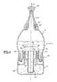
- Figure 1shows an axial section of a two-part package containing three components, in storage position.
- Figure 2shows a section along the plane II-II of Figure 1.
- FIG. 3represents an axial section of the packaging of FIG. 1, in assembly phase.
- FIG. 4represents an axial section of the packaging of FIG. 1 in mixing phase of the three components.
- the first part 2consists of an upper bottle 6 containing the component A, for example an oxidant, intended to be mixed, at the time of use, with the component B, for example an oxidation dye and a third component C, for example a perfume, enclosed separately respectively, in a lower bottle 8 with two compartments 10, 12.
- the two compartments 10, 12constitute the second part 4 of the device.
- the bottle 6is open at its base, which is constituted by a first neck cylindrical 14 carrying an external thread 16.
- the neck 14is connected to the body of bottle 6 by a shoulder 18.
- a second neck 20, of smaller diameter that the diameter of the first neck,is arranged on the opposite end to this latest.
- the second neck 20is provided with an external thread 22 on which is screwed on a closed dispensing tip 24, the tip 26 of which can be broken for the creation of an opening at the time of use, with a view to applying the product.
- An intermediate piece 30comprising a cylindrical hoop 31 is fixed to the neck 14 of the bottle 6 and constitutes coupling means between the bottle upper 6 and the lower bottle 8.
- This intermediate piece 30, produced in rigid thermoplastic material,has a central chimney 32, of substantially cylindrical shape, the upper end 34 of which ends at the inside of the bottle 6.
- This end 34defines an orifice which is closed, in the storage position shown in Figure 1, by an element removable closure 36.
- the closure element 36is present. under the shape of a circular cup which is forcibly engaged, in a leaktight manner, in the passage orifice 34, the peripheral edge of the plugging element comprising a circular groove 38 capable of being clipped onto the end 34 of the central chimney 32.
- the plugging element 36can be separated from the central chimney under the action of an axial thrust.
- the middle part of this central chimney 32has an internal thread 35 whose role will be explained further.
- the lower end 33 of the intermediate piece 30is folded outwards U-shaped so that an outer skirt 30a is formed, concentric with the central chimney 32.
- a groove annularis defined, an inner surface of this groove comprising a thread 41 able to cooperate with the external thread 16 of the bottle 6.
- the part intermediate 30has an external skirt 42 constituting a skirt covering which makes the junction between the upper bottle 6 and the lower bottle 8 (see Figure 3), and which aligns with the outline of the two bottles 6 and 8.
- the lower bottle 8comprises a body 48 containing component B, this body being surmounted by the cylindrical neck 50, the height of the neck 50 being. greater than the height of the central chimney 32.
- the neck 50has a external thread 52 cooperating with a corresponding internal thread 54 of the cap 46.
- the neck 50is disposed a compartment 12 containing the component C.
- the compartment 12has a cylindrical body 56 closed by a bottom 57 extending to the proximity of the bottom 8a of the lower bottle 8, and having an open end 12a.
- the outside diameter of the body 56is clearly less than the internal diameter of the neck 50.
- Four fins 58are provided extending radially outward, to connect the body 56 to a ring of cylindrical connection 60 which is forced into the neck 50 (see. especially in Figure 2).
- An annular projection 62 made on the part upper body 56ensures good height adjustment of body 56 in pass 50.
- the stopper 46simultaneously seals the neck 50 of the lower bottle 8 and the compartment 12.
- the internal face of the plug 46includes a annular sealing skirt 64, suitable for applying to the internal face of the connection ring 60.
- a central pin 66is provided on the face internal of the stopper, capable of being inserted in a sealed manner in the end open 12a in compartment 12.
- FIG. 4shows the removable element 36 completely expelled into the bottle 6.
- the containers 6, 8 and 12are in communication, and components A, B and C mix.
- the userremoves the tip 26.
- the dispensing nozzle 24directed downwards, a dose of the mixture is distributed. This distribution is facilitated when one of the vials 6 or 8 is compressible.
- the upper bottle 6is made of a material semi-rigid thermoplastic such as polyethylene or polypropylene.
- the distribution nozzle 24 and the coupling part intermediate 30are made, for example, of rigid polypropylene.
- the lower bottle 8advantageously, it is made of glass or PVC (polyvinyl chloride) allowing to condition in good storage conditions, for example, a hair dye.
- the compartment 12, intended to contain a perfuming composition in the case a hair dye or a perm,is advantageously produced in suitable rigid thermoplastic.
Landscapes
- Engineering & Computer Science (AREA)
- Mechanical Engineering (AREA)
- Package Specialized In Special Use (AREA)
- Closures For Containers (AREA)
Description
Translated fromFrenchLa présente invention se rapporte à un conditionnement, en deux parties,comportant trois compartiments permettant de stocker séparément les unesdes autres, trois composantes d'un produit, notamment liquides, et de lesmélanger au moment de leur utilisation. Ce conditionnement peut servir,notamment pour la conservation d'une teinture capillaire ou d'un produit pourl'ondulation permanente des cheveux, ces produits étant constitués,habituellement, de plusieurs composantes.The present invention relates to a packaging, in two parts,with three compartments to store each one separatelyothers, three components of a product, especially liquids, andmix at the time of use. This packaging can be used,especially for the conservation of a hair dye or a product forpermanent waving of the hair, these products being made up,usually several components.
Un conditionnement en deux parties permettant de stocker deuxcomposantes, et de les mélanger lors de leur utilisation, est décrit dans ledocument EP-A-0 298 357. Ce conditionnement comprend :
- un premier flacon destiné à contenir une première composante, ce flaconétant ouvert à sa base et muni, à son sommet, d'un embout de distribution ;
- une pièce intermédiaire fixée sur la base du premier flacon, et comportantune cheminée centrale propre à recevoir, en partie haute, un obturateuramovible permettant la fermeture du premier flacon ;
- un deuxième flacon, destiné à contenir un deuxième produit, muni d'ungoulot propre à être engagé dans ladite cheminée centrale, ce goulot étantéquipé d'un bouchon de fermeture pour le stockage, des moyens de liaison,en particulier du type filetage, étant prévus entre le goulot et le bouchon,l'ensemble étant tel que lorsque le bouchon est retiré du deuxième flacon, legoulot de ce dernier peut expulser l'obturateur pour permettre le mélange descomposantes.
- a first bottle intended to contain a first component, this bottle being open at its base and provided, at its top, with a dispensing nozzle;
- an intermediate piece fixed on the base of the first bottle, and comprising a central chimney suitable for receiving, in the upper part, a removable shutter allowing the closure of the first bottle;
- a second bottle, intended to contain a second product, provided with a neck suitable for being engaged in said central chimney, this neck being equipped with a closure cap for storage, connection means, in particular of the threading type, being provided between the neck and the stopper, the assembly being such that when the stopper is removed from the second bottle, the neck of the latter can expel the shutter to allow the components to be mixed.
Le document DE GM 87 00 341 décrit un conditionnement pour le stockageséparé de trois composantes, à mélanger lors de l'utilisation. Ceconditionnement comprend :
- un premier récipient supérieur, cylindrique muni d'un embout de distributioncontenant une première composante,
- un corps inférieur cylindrique muni d'un fond auquel sont raccordés deuxcylindres concentriques de même hauteur, le cylindre intérieur constituant unsecond récipient contenant une seconde composante, un troisième récipientétant délimité par le volume défini entre les deux cylindres et le fond etcontenant une troisième composante. Un bouchon comportant deux jupesannulaires est prévu pour obturer simultanément les seconde et troisièmecompartiments. Le bouchon comporte, en outre une pluralité d'ailettesradiales destinées à s'accrocher sur un rebord interne du premier récipient,lorsque le premier récipient subit une translation relative par rapport ausecond récipient, en vue de désolidariser le bouchon du second et dutroisième récipient et d'effectuer ainsi le mélange des trois composantes.
- a first upper, cylindrical container provided with a dispensing nozzle containing a first component,
- a cylindrical lower body provided with a bottom to which two concentric cylinders of the same height are connected, the inner cylinder constituting a second container containing a second component, a third container being delimited by the volume defined between the two cylinders and the bottom and containing a third component. A stopper comprising two annular skirts is provided for simultaneously closing the second and third compartments. The cap further comprises a plurality of radial fins intended to hang on an internal rim of the first container, when the first container undergoes a relative translation relative to the second container, in order to separate the cap from the second and from the third. container and thus effect the mixing of the three components.
Par des essais, la demanderesse a constaté que, fréquemment, le bouchonrestait accroché sur les second et troisième récipients et que le mélange destrois composantes ne pouvait donc pas être effectué.By tests, the Applicant has found that, frequently, the stopperremained attached to the second and third containers and that the mixture ofthree components therefore could not be performed.
Aussi, la présente invention à pour but de fournir un conditionnement dugenre en question dont la fabrication reste simple et aussi économique quepossible, qui permette un stockage dans de bonnes conditions, sous unencombrement réduit et qui soit d'une mise en oeuvre simple, rapide. Grâce àl'invention, il est possible de conditionner, en toute sécurité, plusieurscomposantes, notamment de nature corrosive, qui ne doivent venir aucontact, les unes avec les autres, qu'au moment de l'utilisation.Also, the present invention aims to provide a packaging of thegenre in question whose manufacture remains simple and as economical aspossible, which allows storage in good conditions, under areduced size and which is simple, quick to implement. Thanks tothe invention, it is possible to condition, safely, severalcomponents, in particular of a corrosive nature, which must notcontact, with each other, only at the time of use.
La présente invention a pour objet un conditionnement permettant deconserver séparément trois composantes de consistance liquide oupulvérulente, et de les mélanger au moment de leur emploi, comprenant :
Grâce à l'agencement du conditionnement de l'invention, il est possibled'assurer la bonne conservation des composantes, avant leur mélange,pendant le stockage et/ou le transport, pendant une durée de conservationélevée, d'une part sans fuite de produit vers l'extérieur, et, d'autre part sansmise en contact intempestive d'une composante avec l'une des autrescomposantes.Thanks to the arrangement of the packaging of the invention, it is possibleto ensure the good conservation of the components, before their mixing,during storage and / or transport, during a shelf lifehigh, on the one hand without product leaking to the outside, and on the other hand withoutinadvertent contact of a component with one of the otherscomponents.
Pour assurer le montage du troisième récipient dans le second, le troisièmerécipient est porté par une pluralité d'ailettes radiales disposéesrégulièrement, au voisinage de ladite ouverture, entre la surface extérieure dutroisième récipient et une surface interne d'un élément de montage disposé àl'intérieur du col du second récipient.To ensure the mounting of the third container in the second, the thirdcontainer is carried by a plurality of radial fins arrangedregularly, in the vicinity of said opening, between the outer surface of thethird container and an inner surface of a mounting member disposedinside the neck of the second container.
Selon un mode de réalisation avantageux, cet élément de montage est montéà force, par exemple par claquage, à l'intérieur dudit col du second récipient.According to an advantageous embodiment, this mounting element is mountedby force, for example by snapping, inside said neck of the second container.
Ce montage est effectué, selon un mode de réalisation intéressant del'invention, de sorte que le troisième récipient soit disposé, de façonconcentrique, à l'intérieur du col du second récipient.This assembly is carried out, according to an interesting embodiment ofthe invention, so that the third container is arranged, soconcentric, inside the neck of the second container.
Dans ce cas, le bouchon comporte un organe central, par exemple un picot,formant saillie, et dont le diamètre extérieur est tel que, en position defermeture du bouchon, ledit organe central obture de manière étanche laditeouverture. Avantageusement, le bouchon est fixé par vissage sur le col dusecond récipient.In this case, the stopper has a central member, for example a spike,protruding, and whose outside diameter is such that, in the position ofclosure of the cap, said central member seals said sealopening. Advantageously, the cap is fixed by screwing on the neck of thesecond container.
Pour assurer une application localisée du mélange obtenu, le premierrécipient, du côté opposé à la frette, peut être muni, à son sommet, d'unembout de distribution fermé par une pointe ou patte qui peut être cassée parl'utilisateur.To ensure localized application of the mixture obtained, the firstcontainer, on the side opposite the hoop, can be provided, at its top, with adispensing nozzle closed by a point or tab which can be broken bythe user.
Selon un aspect intéressant de l'invention, la pièce intermédiaire comportedes moyens de couplage, prévus entre la cheminée centrale et le col dusecond récipient, de manière à permettre, en réponse à une rotation dusecond récipient par rapport au premier, un mouvement axial du secondrécipient par rapport au premier, et l'expulsion de l'obturateur.According to an interesting aspect of the invention, the intermediate piece comprisescoupling means, provided between the central chimney and the neck of thesecond container, so as to allow, in response to rotation of thesecond container relative to the first, an axial movement of the secondcontainer relative to the first, and the expulsion of the shutter.
Avantageusement, les moyens de couplage comportent un filetage interneporté par une surface intérieure de la cheminée centrale, et apte à coopéreravec un filetage externe porté par le col du second récipient.Advantageously, the coupling means comprise an internal threadcarried by an inner surface of the central chimney, and able to cooperatewith an external thread carried by the neck of the second container.
Pour assurer le raccordement de la pièce intermédiaire sur le premierrécipient, la pièce intermédiaire peut être vissée sur un col. Le vissageprocure un assemblage particulièrement étanche, mais un système àclaquage est envisageable, également.To ensure the connection of the intermediate piece on the firstcontainer, the intermediate piece can be screwed onto a neck. The screwingprovides a particularly tight assembly, but abreakdown is also possible.
Afin que l'utilisateur puisse effectuer la distribution du mélange obtenu, lepremier récipient peut être réalisé en un matériau thermoplastiquecompressible, permettant d'expulser une dose précise de produit à l'endroitsouhaité. Ce matériau est choisi, par exemple, parmi les polyéthylènes bassedensité.So that the user can distribute the mixture obtained, thefirst container can be made of a thermoplastic materialcompressible, allowing to expel a precise dose of product at the placewish. This material is chosen, for example, from low polyethylenesdensity.
Quant au second récipient, il est réalisé en un matériau thermoplastiquerigide, tel que du polypropylène ou du PVC (chlorure de polyvinyle), ou bienen verre. Un récipient réalisé en ce dernier matériau permet de stocker, dansde bonnes conditions, des composantes corrosives comme l'eau oxygénée,ou des substances susceptibles de se dégrader, comme les colorants utiliséshabituellement en teinture capillaire.As for the second container, it is made of a thermoplastic materialrigid, such as polypropylene or PVC (polyvinyl chloride), or elseglass. A container made of this latter material makes it possible to store, ingood conditions, corrosive components like hydrogen peroxide,or substances liable to degrade, such as the dyes usedusually in hair dye.
Dans le cas d'une teinture capillaire, le premier récipient contient l'oxydant, telque, par exemple l'eau oxygénée, le second récipient contenant le colorant etle troisième récipient contenant un parfum ou un agent de conditionnementcapillaire.In the case of a hair dye, the first container contains the oxidant, such asthat, for example hydrogen peroxide, the second container containing the dye andthe third container containing a perfume or a conditioning agentcapillary.
Pour mieux faire comprendre la présente invention, on va décrire maintenant,à titre d'exemple purement illustratif et nullement limitatif, un mode deréalisation d'un conditionnement conforme à l'invention, représenté sur lesdessins annexés.To better understand the present invention, we will now describe,as a purely illustrative and in no way limiting example, a method ofproduction of a packaging in accordance with the invention, shown in theattached drawings.
Conformément à un mode de réalisation de l'invention, la figure 1 représenteune coupe axiale d'un conditionnement en deux parties renfermant troiscomposantes, en position de stockage.According to an embodiment of the invention, Figure 1 showsan axial section of a two-part package containing threecomponents, in storage position.
La figure 2 présente une coupe, selon le plan II-II de la figure 1.Figure 2 shows a section along the plane II-II of Figure 1.
La figure 3 représente une coupe axiale du conditionnement de la figure 1, enphase d'assemblage.FIG. 3 represents an axial section of the packaging of FIG. 1, inassembly phase.
La figure 4 représente une coupe axiale du conditionnement de la figure 1 enphase de mélange des trois composantes.FIG. 4 represents an axial section of the packaging of FIG. 1 inmixing phase of the three components.
En se reportant aux dessins, notamment à la figure 1, on peut voir unconditionnement 1 en deux parties 2, 4, permettant de stocker séparémentles unes des autres, trois composantes A, B, C, généralement liquides, et deles mélanger juste avant leur utilisation. :
La première partie 2 est constituée d'un flacon supérieur 6 contenant lacomposante A, par exemple un oxydant, destiné à être mélangé, au momentde l'utilisation, avec la composante B, par exemple un colorant d'oxydation etune troisième composante C, par exemple un parfum, renfermérespectivement de manière séparée, dans un flacon inférieur 8 à deuxcompartiments 10, 12. Les deux compartiments 10,12 constituent ladeuxième partie 4 du dispositif.Referring to the drawings, in particular in FIG. 1, one can see a
The
Le flacon 6 est ouvert à sa base, laquelle est constituée par un premier colcylindrique 14 portant un filetage externe 16. Le col 14 est raccorde au corpsde flacon 6 par un épaulement 18. Un second col 20, de diamètre plus petitque le diamètre du premier col, est disposé sur l'extrémité opposée à cedernier. Le second col 20 est pourvu d'un filetage externe 22 sur lequel estvissé un embout de distribution 24 fermé, dont la pointe 26 peut être casséepour la création d'une ouverture au moment de l'utilisation, en vue d'appliquerle produit.The
Une pièce intermédiaire 30 comportant une frette cylindrique 31 est fixée surle col 14 du flacon 6 et constitue des moyens de couplage entre le flaconsupérieur 6 et le flacon inférieur 8. Cette pièce intermédiaire 30, réalisée enmatériau thermoplastique rigide, comporte une cheminée centrale 32, deforme sensiblement cylindrique, dont l'extrémité supérieure 34 se termine àl'intérieur du flacon 6. Cette extrémité 34 délimite un orifice qui est obturé,dans la position de stockage représenté sur la figure 1, par un élémentamovible de bouchage 36. L'élément de bouchage 36 se présente. sous laforme d'une coupelle circulaire qui est engagée à force, de manière étanche,dans l'orifice de passage 34, le bord périphérique de l'élément de bouchagecomportant une gorge circulaire 38 apte à se clipser sur l'extrémité 34 de lacheminée centrale 32. L'élément de bouchage 36 peut être séparé de lacheminée centrale sous l'action d'une poussée axiale. La partie médiane de cette cheminée centrale 32 comporte un filetage interne 35 dont le rôle seraexpliqué plus loin.An
L'extrémité inférieure 33 de la pièce intermédiaire 30 est replié vers l'extérieuren forme de "U" de sorte qu'une jupe externe 30a est formée, concentriqueavec la cheminée centrale 32. Par cette configuration en "U", une gorgeannulaire est définie, une surface intérieure de cette gorge comportant unfiletage 41 apte coopérer avec le filetage externe 16 du flacon 6. La pièceintermédiaire 30 comporte une jupe externe 42 constituant une juped'habillage qui fait la jonction entre le flacon supérieur 6 et le flacon inférieur 8(voir figure 3), et qui s'aligne avec le contour des deux flacons 6 et 8.The
Dans l'extrémité inférieure 33 de la frette est pourvu un alésage interne 44 dediamètre légèrement plus important que le diamètre du filetage 35, propre àcréer un volume cylindrique dans lequel peut être logé un bouchon 46 deforme sensiblement cylindrique. Ce bouchon est monté, par vissage, sur uncol cylindrique 50 du flacon inférieur 8.In the
Le flacon inférieur 8 comporte un corps 48 contenant la composante B, cecorps étant surmonté du col cylindrique 50, la hauteur du col 50 étant.supérieure à la hauteur de la cheminée centrale 32. Le col 50 comporte unfiletage externe 52 coopérant avec un filetage interne 54 correspondant dubouchon 46.The
Dans le col 50 est disposé un compartiment 12 contenant la composante C.Le compartiment 12 présente un corps cylindrique 56 fermé par un fond 57s'étendant jusqu'à la proximité du fond 8a du flacon inférieur 8, et présentantune extrémité ouverte 12a. Le diamètre extérieur du corps 56 est nettementinférieur au diamètre interne du col 50. Quatre ailettes 58 sont prévuess'étendant radialement vers l'extérieur, pour relier le corps 56 à une bague deraccordement cylindrique 60 qui est insérée à force dans le col 50 (voir.notamment sur la figure 2). Une saillie annulaire 62 pratiquée sur la partiesupérieure du corps 56 assure le bon ajustement en hauteur du corps 56dans le col 50.In the
Le bouchon 46 obture simultanément le col 50 du flacon inférieur 8 et lecompartiment 12. A cet effet, la face interne du bouchon 46 comporte unejupe annulaire 64 d'étanchéité, propre à s'appliquer sur la face interne de labague de raccordement 60. En outre, un picot central 66 est prévu sur la faceinterne du bouchon, apte à s'insérer, de manière étanche, dans l'extrémitéouverte 12a du compartiment 12.The
Le fonctionnement du conditionnement qui vient d'être décrit est illustré surles figures 3 et 4. Comme visible, notamment sur la figure 3, l'utilisateurenlève, par dévissage, le bouchon 46 du flacon inférieur 8. Tout enmaintenant ce flacon droit, il pose alors le flacon supérieur 6 sur le goulot 50du flacon inférieur 8. En effectuant un mouvement de vissage, le filetage 52du goulot 50 s'engage alors dans les spires du filetage 35 de la cheminée 32.The operation of the packaging which has just been described is illustrated onFigures 3 and 4. As visible, in particular in Figure 3, the userremove, by unscrewing, the
Au bout de quelques tours de vissage, le goulot 52 vient en appui contrel'élément amovible 36 de bouchage. Il est à noter, qu'un ergot 68 est prévusur la face inférieure de l'élément amovible 36, permettant d'amorcer sondésengagement de l'extrémité supérieure 34 de la cheminée centrale 32. Encontinuant le vissage, l'élément amovible 36 se soulève, comme symbolisépar la flèche F sur la figure 3. La figure 4 montre alors l'élément amovible 36complètement expulsé dans le flacon 6. Dans cette position, les récipients 6,8 et 12 sont en communication, et les composantes A, B et C se mélangent.Par agitation de l'ensemble du conditionnement, on peut assurer un mélangehomogène. Avant d'appliquer le mélange ainsi obtenu sur l'endroit désiré, parun mouvement de torsion, l'utilisateur enlève la pointe 26. En retournantl'ensemble, l'embout de distribution 24 dirigé vers le bas, une dose dumélange est distribuée. Cette distribution est facilitée, lorsque l'un des flacons6 ou 8 est compressible.After a few screwing turns, the
Avantageusement, le flacon supérieur 6 est réalisé en un matériauthermoplastique semi-rigide comme le polyéthylène ou le polypropylène.Ainsi, le flacon supérieur 6 peut être comprimé lors de la distribution duproduit mélangé. L'embout de distribution 24 et la pièce de couplageintermédiaire 30 sont réalisés, par exemple, en polypropylène rigide. Quantau flacon inférieur 8, avantageusement, il est réalisé en verre ou en PVC(chlorure de polyvinyle) permettant de conditionner dans de bonnesconditions de conservation, par exemple, un colorant capillaire. Lecompartiment 12, destiné à contenir une composition parfumante dans le casd'une teinture capillaire ou d'une permanente, est réalisé avantageusementen thermoplastique rigide approprié.Advantageously, the
Claims (12)
- Packaging (1) in which three components (A, B, C)of liquid or powdery consistency can be kept separatelyand mixed at the time of their use, comprising:which packaging ischaracterized in that the secondreceptacle (8) comprises an element defining a thirdreceptacle (12) for containing, separately from thesecond component (B), a third component (C), the saidthird receptacle having a rim (12a) defining an openingwhich during storage is closed by the said stopper.a) a first receptacle (6) designed to contain a firstcomponent (A), this receptacle being open at its base,b) an intermediate part (30) attached to the base ofthe first receptacle (6) and comprising a centralsleeve (32) able to receive a removable cap (36) forthe closure of the base of the first receptacle (6),andc) a second receptacle (8) that is designed to containa second component (B) and has a neck (50) which isable to be engaged in the said central sleeve (32),this neck being equipped with a stopper (46) forstorage purposes, the assembly being such that when thestopper is withdrawn from the second receptacle, theneck (50) of the latter can, when inserted into thecentral sleeve (32), expel the cap (36) and allow thecomponents (A, B, C) to be mixed,
- Packaging according to Claim 1,characterized inthat the third receptacle (12) is supported by a plurality of regularly arranged radial spokes (58), inthe vicinity of the said opening (12a) between theouter surface of the third receptacle (12) and an innersurface of a location element (60) positioned insidethe said neck (50).
- Packaging according to Claim 2,characterized inthat the location element (60) is snap-fitted into thesaid neck (50).
- Packaging according to any one of Claims 1 to 3,characterized in that the third receptacle (12) ispositioned concentrically inside the neck (50).
- Packaging according to Claim 4,characterized inthat the stopper (46) comprises a projecting centralmember (66) whose outside diameter is such that, whenthe stopper is in the closing position, the saidcentral member (66) seals the said opening defined bythe rim (12a).
- Packaging according to any one of Claims 1 to 5,characterized in that the first receptacle (6) isprovided at its top with a dispensing nozzle (24)closed by a breakable tip (26).
- Packaging according to any one of Claims 1 to 6,characterized in that the intermediate part (30) formsmeans for connecting the central sleeve (32) to theneck (50) of the second receptacle (8), in such a wayas to make possible, in response to rotation of thesecond receptacle with respect to the first, an axialmovement of the second receptacle (8) with respect tothe first (6), and expulsion of the cap (36).
- Packaging according to Claim 7,characterized inthat the connecting means (30) comprise an internalthread (35) on an inner surface of the central sleeve (34), for engagement with an external thread (52) onthe neck (50) of the second receptacle (8).
- Packaging according to any one of the precedingclaims,characterized in that the intermediate part(30) is screwed onto a neck (14) formed in the vicinityof the open base of the first receptacle (6).
- Packaging according to any one of the precedingclaims,characterized in that the first receptacle (6)is made of a compressible thermoplastic material.
- Packaging according to any one of the precedingclaims,characterized in that the second receptacle (8)is made of a rigid thermoplastic material or of glass.
- Packaging according to any one of the precedingclaims,characterized in that it contains a hair dye,the first receptacle (6) containing an oxidizing agent(A), the second receptacle (8) containing a colorant(B) and the third receptacle (12) containing afragrance (C).
Applications Claiming Priority (2)
| Application Number | Priority Date | Filing Date | Title |
|---|---|---|---|
| FR9711887AFR2768705B1 (en) | 1997-09-24 | 1997-09-24 | PACKAGING FOR A THREE-COMPONENT PRODUCT |
| FR9711887 | 1997-09-24 |
Publications (2)
| Publication Number | Publication Date |
|---|---|
| EP0905049A1 EP0905049A1 (en) | 1999-03-31 |
| EP0905049B1true EP0905049B1 (en) | 2003-06-25 |
Family
ID=9511426
Family Applications (1)
| Application Number | Title | Priority Date | Filing Date |
|---|---|---|---|
| EP19980401660RevokedEP0905049B1 (en) | 1997-09-24 | 1998-07-02 | Container for a three-component product |
Country Status (4)
| Country | Link |
|---|---|
| EP (1) | EP0905049B1 (en) |
| DE (1) | DE69815776T2 (en) |
| ES (1) | ES2201422T3 (en) |
| FR (1) | FR2768705B1 (en) |
Cited By (2)
| Publication number | Priority date | Publication date | Assignee | Title |
|---|---|---|---|---|
| US8590753B2 (en) | 2008-08-29 | 2013-11-26 | Pepsico, Inc. | Post-mix beverage system |
| US9272827B2 (en) | 2008-08-29 | 2016-03-01 | Pepsico, Inc. | Post-mix beverage system |
Families Citing this family (10)
| Publication number | Priority date | Publication date | Assignee | Title |
|---|---|---|---|---|
| FR2789979B1 (en)* | 1999-02-22 | 2001-05-04 | Oreal | PACKAGING FOR MIXING A MULTI-COMPONENT PRODUCT |
| DE19958920C2 (en)* | 1999-12-07 | 2003-03-20 | Automation Industrielle Sa | Two-chamber container |
| DE102008017468B4 (en)* | 2008-04-03 | 2015-08-20 | Sanner Gmbh | Container for dry storage of a packaged good |
| JP2012515121A (en)* | 2009-01-12 | 2012-07-05 | アクティヴパック, インコーポレイテッド | Packaged products, inserts and compartments for aseptic mixing of substances and methods for use therewith |
| RU2590993C2 (en)* | 2012-01-03 | 2016-07-10 | Пепсико, Инк. | Beverage mixing system |
| US10464797B2 (en) | 2016-01-15 | 2019-11-05 | Pepsico, Inc. | Post-mix beverage system |
| US10610045B2 (en) | 2016-06-14 | 2020-04-07 | Pepsico, Inc. | Beverage system including a removable piercer |
| KR101959279B1 (en)* | 2017-03-23 | 2019-03-18 | (주)황초원 | Portable drink container including portion pack and holdercap |
| WO2018174429A1 (en)* | 2017-03-23 | 2018-09-27 | (주)황초원 | Portable beverage container including portion pack and fixing cap |
| MX2022011091A (en)* | 2020-03-18 | 2022-12-15 | Brev Angela Srl | Pre-filled container, method of use and related production method. |
Family Cites Families (9)
| Publication number | Priority date | Publication date | Assignee | Title |
|---|---|---|---|---|
| US3603484A (en)* | 1969-02-28 | 1971-09-07 | Mix O Matic Corp | A two-compartment mixing and dispensing device |
| US3696919A (en)* | 1970-10-08 | 1972-10-10 | Colgate Palmolive Co | Double container with mixing means |
| FR2590235B1 (en)* | 1985-11-20 | 1988-01-22 | Oreal | PACKAGING TWO COMPARTMENTS SEPARATED BY A TEAR-OFF LID |
| DE8700341U1 (en) | 1987-01-08 | 1988-05-05 | Wella Ag, 64295 Darmstadt | Multi-chamber container for pourable substances |
| DE3722371A1 (en) | 1987-07-07 | 1989-01-19 | Henkel Kgaa | TWO-CHAMBER CONTAINER |
| FR2680357B1 (en)* | 1991-08-16 | 1995-01-06 | Oreal | PACKAGING WITH TWO BOTTLES FOR SEPARATELY STORING ONE OF THE OTHER TWO PRODUCTS, PARTICULARLY LIQUID, AND MIXING THEM AT THE TIME OF THEIR USE. |
| DE69307836T2 (en)* | 1992-06-09 | 1997-06-12 | Soc D Conseils Et D Etudes Des | MIXING AND DISPENSING CONTAINER WITH TWO CHAMBERS |
| US5647481A (en)* | 1995-05-17 | 1997-07-15 | Henkel Kommanditgesellschaft Auf Aktien | Dual container system for two component hair dye |
| FR2763048B1 (en)* | 1997-05-06 | 1999-07-09 | Oreal | PACKAGING FOR THE EXTEMPORANEOUS MIXTURE OF TWO PRODUCTS |
- 1997
- 1997-09-24FRFR9711887Apatent/FR2768705B1/ennot_activeExpired - Fee Related
- 1998
- 1998-07-02EPEP19980401660patent/EP0905049B1/ennot_activeRevoked
- 1998-07-02ESES98401660Tpatent/ES2201422T3/ennot_activeExpired - Lifetime
- 1998-07-02DEDE69815776Tpatent/DE69815776T2/ennot_activeRevoked
Cited By (3)
| Publication number | Priority date | Publication date | Assignee | Title |
|---|---|---|---|---|
| US8590753B2 (en) | 2008-08-29 | 2013-11-26 | Pepsico, Inc. | Post-mix beverage system |
| US8740020B2 (en) | 2008-08-29 | 2014-06-03 | Pepsico, Inc. | Post-mix beverage system |
| US9272827B2 (en) | 2008-08-29 | 2016-03-01 | Pepsico, Inc. | Post-mix beverage system |
Also Published As
| Publication number | Publication date |
|---|---|
| EP0905049A1 (en) | 1999-03-31 |
| DE69815776D1 (en) | 2003-07-31 |
| ES2201422T3 (en) | 2004-03-16 |
| FR2768705B1 (en) | 1999-11-19 |
| DE69815776T2 (en) | 2004-04-29 |
| FR2768705A1 (en) | 1999-03-26 |
Similar Documents
| Publication | Publication Date | Title |
|---|---|---|
| EP0694483B1 (en) | Container for the storage of at least two products, and for the mixture and distribution of these products | |
| CA2298302C (en) | Device for storage of three components, their mixing and distribution of the mixture obtained | |
| CA2141967C (en) | Multiple compartment dispenser for storing and blending contents | |
| EP1044893B1 (en) | Device for the extemporaneous mixture of at least two products, of which one is a powder | |
| EP0881165B1 (en) | Packaging container for extemporaneously mixing two products | |
| EP1033323B1 (en) | Container for mixing a product made of several components | |
| EP0572645B1 (en) | Assembly for mixing two different separately-stored products | |
| EP0899210B1 (en) | Device for the instant mixing of at least two components | |
| CA1275077A (en) | Container for conditioning and distributing a liquid and at least one additional product segregated while in storage | |
| EP1136386B1 (en) | Device for the extemporaneous mixture of at least two products | |
| EP0293290A1 (en) | Closure device for containers | |
| EP0528707A1 (en) | Package with two bottles for separately storing two products, in particular liquids, and to mix them together prior to use | |
| FR2765859A1 (en) | DEVICE FOR PACKAGING TWO COMPONENTS | |
| EP0238371B1 (en) | Container for a viscous liquid to which an additive is added when first used | |
| EP0905049B1 (en) | Container for a three-component product | |
| FR2765861A1 (en) | DEVICE FOR THE SEPARATE PACKAGING OF TWO COMPONENTS AND MANUFACTURING PROCESS | |
| EP1707495A1 (en) | Device for holding and mixing two products | |
| EP1072527A1 (en) | Package for viscous products with increased rate of emptying | |
| WO2008152219A1 (en) | Cap for receptacle forming an additive reservoir | |
| FR2687640A1 (en) | Device for preserving at least two products separated from one another and for mixing them subsequently, particularly at the time of use | |
| EP0638485B1 (en) | Device for packaging and dispensing a mixture of two products which are maintained isolated from each other before the dispensing operation | |
| EP0805113A1 (en) | Tamper-evident closure for containers,in particular for bottles or vials | |
| FR3066478A1 (en) | ASSEMBLY FOR PACKAGING A FLUIDIC PRODUCT |
Legal Events
| Date | Code | Title | Description |
|---|---|---|---|
| PUAI | Public reference made under article 153(3) epc to a published international application that has entered the european phase | Free format text:ORIGINAL CODE: 0009012 | |
| AK | Designated contracting states | Kind code of ref document:A1 Designated state(s):DE ES FR GB IT | |
| AX | Request for extension of the european patent | Free format text:AL;LT;LV;MK;RO;SI | |
| 17P | Request for examination filed | Effective date:19990930 | |
| AKX | Designation fees paid | Free format text:DE ES FR GB IT | |
| 17Q | First examination report despatched | Effective date:20020208 | |
| GRAH | Despatch of communication of intention to grant a patent | Free format text:ORIGINAL CODE: EPIDOS IGRA | |
| GRAH | Despatch of communication of intention to grant a patent | Free format text:ORIGINAL CODE: EPIDOS IGRA | |
| GRAA | (expected) grant | Free format text:ORIGINAL CODE: 0009210 | |
| AK | Designated contracting states | Designated state(s):DE ES FR GB IT | |
| REG | Reference to a national code | Ref country code:GB Ref legal event code:FG4D Free format text:NOT ENGLISH | |
| REF | Corresponds to: | Ref document number:69815776 Country of ref document:DE Date of ref document:20030731 Kind code of ref document:P | |
| GBT | Gb: translation of ep patent filed (gb section 77(6)(a)/1977) | Effective date:20031008 | |
| REG | Reference to a national code | Ref country code:ES Ref legal event code:FG2A Ref document number:2201422 Country of ref document:ES Kind code of ref document:T3 | |
| PLBI | Opposition filed | Free format text:ORIGINAL CODE: 0009260 | |
| PLBQ | Unpublished change to opponent data | Free format text:ORIGINAL CODE: EPIDOS OPPO | |
| PLAX | Notice of opposition and request to file observation + time limit sent | Free format text:ORIGINAL CODE: EPIDOSNOBS2 | |
| 26 | Opposition filed | Opponent name:KPSS-KAO PROFESSIONAL SALON SERVICES GMBH Effective date:20040324 | |
| PLAX | Notice of opposition and request to file observation + time limit sent | Free format text:ORIGINAL CODE: EPIDOSNOBS2 | |
| PLBB | Reply of patent proprietor to notice(s) of opposition received | Free format text:ORIGINAL CODE: EPIDOSNOBS3 | |
| PLAY | Examination report in opposition despatched + time limit | Free format text:ORIGINAL CODE: EPIDOSNORE2 | |
| PLBC | Reply to examination report in opposition received | Free format text:ORIGINAL CODE: EPIDOSNORE3 | |
| PGFP | Annual fee paid to national office [announced via postgrant information from national office to epo] | Ref country code:GB Payment date:20050629 Year of fee payment:8 | |
| PGFP | Annual fee paid to national office [announced via postgrant information from national office to epo] | Ref country code:DE Payment date:20050630 Year of fee payment:8 | |
| PGFP | Annual fee paid to national office [announced via postgrant information from national office to epo] | Ref country code:FR Payment date:20050708 Year of fee payment:8 | |
| PGFP | Annual fee paid to national office [announced via postgrant information from national office to epo] | Ref country code:ES Payment date:20050818 Year of fee payment:8 | |
| PLAY | Examination report in opposition despatched + time limit | Free format text:ORIGINAL CODE: EPIDOSNORE2 | |
| PLBC | Reply to examination report in opposition received | Free format text:ORIGINAL CODE: EPIDOSNORE3 | |
| RDAF | Communication despatched that patent is revoked | Free format text:ORIGINAL CODE: EPIDOSNREV1 | |
| RDAG | Patent revoked | Free format text:ORIGINAL CODE: 0009271 | |
| STAA | Information on the status of an ep patent application or granted ep patent | Free format text:STATUS: PATENT REVOKED | |
| PGFP | Annual fee paid to national office [announced via postgrant information from national office to epo] | Ref country code:IT Payment date:20060731 Year of fee payment:9 | |
| 27W | Patent revoked | Effective date:20051214 | |
| GBPR | Gb: patent revoked under art. 102 of the ep convention designating the uk as contracting state | Free format text:20051214 | |
| PLAB | Opposition data, opponent's data or that of the opponent's representative modified | Free format text:ORIGINAL CODE: 0009299OPPO |