EP0901282B1 - Method for recording and reproducing electronic watermark information - Google Patents
Method for recording and reproducing electronic watermark informationDownload PDFInfo
- Publication number
- EP0901282B1 EP0901282B1EP98306484AEP98306484AEP0901282B1EP 0901282 B1EP0901282 B1EP 0901282B1EP 98306484 AEP98306484 AEP 98306484AEP 98306484 AEP98306484 AEP 98306484AEP 0901282 B1EP0901282 B1EP 0901282B1
- Authority
- EP
- European Patent Office
- Prior art keywords
- watermark information
- signal
- electronic watermark
- reference signal
- video signal
- Prior art date
- Legal status (The legal status is an assumption and is not a legal conclusion. Google has not performed a legal analysis and makes no representation as to the accuracy of the status listed.)
- Expired - Lifetime
Links
Images


Classifications
- G—PHYSICS
- G11—INFORMATION STORAGE
- G11B—INFORMATION STORAGE BASED ON RELATIVE MOVEMENT BETWEEN RECORD CARRIER AND TRANSDUCER
- G11B20/00—Signal processing not specific to the method of recording or reproducing; Circuits therefor
- G11B20/10—Digital recording or reproducing
- G11B20/10527—Audio or video recording; Data buffering arrangements
- G—PHYSICS
- G06—COMPUTING OR CALCULATING; COUNTING
- G06T—IMAGE DATA PROCESSING OR GENERATION, IN GENERAL
- G06T1/00—General purpose image data processing
- G06T1/0021—Image watermarking
- G06T1/005—Robust watermarking, e.g. average attack or collusion attack resistant
- G—PHYSICS
- G06—COMPUTING OR CALCULATING; COUNTING
- G06T—IMAGE DATA PROCESSING OR GENERATION, IN GENERAL
- G06T1/00—General purpose image data processing
- G06T1/0021—Image watermarking
- G06T1/0085—Time domain based watermarking, e.g. watermarks spread over several images
- G—PHYSICS
- G11—INFORMATION STORAGE
- G11B—INFORMATION STORAGE BASED ON RELATIVE MOVEMENT BETWEEN RECORD CARRIER AND TRANSDUCER
- G11B20/00—Signal processing not specific to the method of recording or reproducing; Circuits therefor
- G11B20/00086—Circuits for prevention of unauthorised reproduction or copying, e.g. piracy
- G11B20/00884—Circuits for prevention of unauthorised reproduction or copying, e.g. piracy involving a watermark, i.e. a barely perceptible transformation of the original data which can nevertheless be recognised by an algorithm
- G—PHYSICS
- G11—INFORMATION STORAGE
- G11B—INFORMATION STORAGE BASED ON RELATIVE MOVEMENT BETWEEN RECORD CARRIER AND TRANSDUCER
- G11B27/00—Editing; Indexing; Addressing; Timing or synchronising; Monitoring; Measuring tape travel
- G11B27/10—Indexing; Addressing; Timing or synchronising; Measuring tape travel
- H—ELECTRICITY
- H04—ELECTRIC COMMUNICATION TECHNIQUE
- H04N—PICTORIAL COMMUNICATION, e.g. TELEVISION
- H04N21/00—Selective content distribution, e.g. interactive television or video on demand [VOD]
- H04N21/20—Servers specifically adapted for the distribution of content, e.g. VOD servers; Operations thereof
- H04N21/23—Processing of content or additional data; Elementary server operations; Server middleware
- H04N21/238—Interfacing the downstream path of the transmission network, e.g. adapting the transmission rate of a video stream to network bandwidth; Processing of multiplex streams
- H04N21/2389—Multiplex stream processing, e.g. multiplex stream encrypting
- H04N21/23892—Multiplex stream processing, e.g. multiplex stream encrypting involving embedding information at multiplex stream level, e.g. embedding a watermark at packet level
- H—ELECTRICITY
- H04—ELECTRIC COMMUNICATION TECHNIQUE
- H04N—PICTORIAL COMMUNICATION, e.g. TELEVISION
- H04N21/00—Selective content distribution, e.g. interactive television or video on demand [VOD]
- H04N21/80—Generation or processing of content or additional data by content creator independently of the distribution process; Content per se
- H04N21/83—Generation or processing of protective or descriptive data associated with content; Content structuring
- H04N21/835—Generation of protective data, e.g. certificates
- H04N21/8358—Generation of protective data, e.g. certificates involving watermark
- H—ELECTRICITY
- H04—ELECTRIC COMMUNICATION TECHNIQUE
- H04N—PICTORIAL COMMUNICATION, e.g. TELEVISION
- H04N5/00—Details of television systems
- H04N5/76—Television signal recording
- H04N5/91—Television signal processing therefor
- H04N5/913—Television signal processing therefor for scrambling ; for copy protection
- G—PHYSICS
- G06—COMPUTING OR CALCULATING; COUNTING
- G06T—IMAGE DATA PROCESSING OR GENERATION, IN GENERAL
- G06T2201/00—General purpose image data processing
- G06T2201/005—Image watermarking
- G06T2201/0065—Extraction of an embedded watermark; Reliable detection
- H—ELECTRICITY
- H04—ELECTRIC COMMUNICATION TECHNIQUE
- H04N—PICTORIAL COMMUNICATION, e.g. TELEVISION
- H04N5/00—Details of television systems
- H04N5/76—Television signal recording
- H04N5/91—Television signal processing therefor
- H04N5/913—Television signal processing therefor for scrambling ; for copy protection
- H04N2005/91307—Television signal processing therefor for scrambling ; for copy protection by adding a copy protection signal to the video signal
- H04N2005/91335—Television signal processing therefor for scrambling ; for copy protection by adding a copy protection signal to the video signal the copy protection signal being a watermark
Definitions
- the present inventionrelates to a method for recording and reproducing image data, particularly electronic watermark information embedded (hidden) in video signals, which is used for the picture recording and reproduction control or for marking the origins of the records.
- An aim of the present inventionis to provide a method for recording and reproducing electronic watermark information which enables easy detection of the watermark information at the time of reproducing.
- Another aim of the present inventionis to provide a method for recording and reproducing electronic watermark information which enables easy reproduction of the embedded electronic watermark information even if the reproduction characteristics of the reproduction apparatus vary.
- Still another aim of the present inventionis to provide a method for recording and reproducing electronic watermark information which enables easy reproduction of the electronic watermark information even if the signal level of the watermark information varies.
- the present inventionteaches a method of recording a video signal, electronic watermark information which is embedded in the video signal and a reference signal which is inserted at a position different from the position of the watermark information in the video signal.
- the present inventionprovides a method of recording electronic watermark information as set out in claim 1.
- the methodmay also include detecting or reproducing the reference signal, and modifying the watermark information based on the reference signal.
- the watermark informationis derived from the luminance signal included in a video signal, with the luminous value of the luminance signal being altered at a predetermined position within the calculated alteration range.
- the present inventionprovides a method of reproducing electronic watermark information according to claim 9.
- the inventive methodis designed to append preparatorily a reference signal used for the detection of electronic watermark information at a specific position of a video signal and reproduce the watermark information based on this reference signal at the time of reproducing.
- the reference signalis embedded within the period of horizontal sync signal outside the picture display period, i.e., in the back-porch or front-porch portion, or outside the picture display area. At the time of detection, the embedded electronic watermark information is reproduced based on the reference signal level.
- the reference signalmay be recorded within the period of vertical sync signal.
- a reference timing signalis recorded at the head of the video signal so that the recording level and recording position of the electronic watermark information are detected based on the reference signal level and reproduction timing at the time of reproducing.
- Fig.1is a schematic diagram showing the reference signal and the recording position thereof used by the method and apparatus for recording and reproducing electronic watermark information based on an embodiment of this invention.
- numeral 1denotes the picture display area of a display apparatus such as a television receiver
- 2is the over-scan area which is the remaining portion of the area enclosed by the dashed lines excluding the picture display area 1
- 3indicates the insertion position of the reference signal recorded in the over-scan area 2.
- the reference signal which takes up one or more linesis inserted or added to a video signal.
- the video signal, with the reference signal being appended thereto,is recorded on a recording medium.
- the reference signalis included in the video signal so that it is located preferably in the over-scan area, instead of the picture display area 1 in which case the video signal would possibily be disturbed.
- Fig.2is a schematic diagram showing the reference signals and the recording position thereof used by the method and apparatus for recording and reproducing electronic watermark information and the recording medium based on another embodiment of this invention.
- reference signals 4 and 5are inserted or added to a video signal so that the signals 4 and 5 are located within the upper over-scan area and lower over-scan area, respectively, and each included in one or more lines of the video signal.
- TV signalsare liable to sag at the top and bottom of the screen due to the influence of the transmission system. Specifically, when a TV signal for producing a constant luminance over the entire screen is transmitted, it varies due to the influence of the transmission system, resulting in a varied displayed luminance at the top and bottom of the screen. This phenomenon is pronounced particularly in gray colors.
- the embodiment of Fig.2is intended to correct the luminance variation by inserting the reference signals 4 and 5 at the top and bottom of the over-scan area.
- the detection level or luminous value of the electronic watermark informationis corrected by use of the reference signal 4 for the top of the screen and the reference signal 5 for the bottom of the screen.
- the mean value of the upper and lower reference signals 4 and 5may be used for the correction. Consequently, even if the luminance variation arises due to the sag, the detection level of electronic watermark information can be corrected.
- Fig.3is a schematic diagram showing the reference signals and the recording position thereof used by the method and apparatus for recording and reproducing electronic watermark information and the recording medium based on still another embodiment of this invention.
- reference signals 6 and 7are inserted to take up part of the top of and part of the bottom of the over-scan area 2.
- the reference signals 6 and 7are recorded to locate at the corners of the screen, instead of the entire lines, in which case the signals 6 and 7 would distribute the video signal in its picture display period.
- a reference signalmay be recorded to locate only at the top or bottom of the over-scan area 2, instead of inserting the reference signals 6 and 7 to locate in part of the top of and part of the bottom of the over-scan area 2.
- the headis switched at the lower side of the tape, allowing of less space for the reference signal 7, and therefore it is advantageous to adopt the reference signal 6 in the larger area of the upper side of the tape.
- the reference signals 6 and 7 added to the video signalhave the peak white level in terms of the luminance signal. Accordingly, in case the video signal has its luminance varied in order to embed electronic watermark information, the correct watermark information can be obtained by modifying the luminance of the video signal by use of the reference signals 6 and 7. Namely, the electronic watermark information is embedded in the video signal in terms of the varied luminance of the video signal, as will be explained in detail later, and the luminance level varied by the transmission system can be corrected by use of the reference signals 6 and 7, whereby the watermark information can be detected easily.
- Fig.4is a schematic diagram showing the reference signals and the recording position thereof used by the method and apparatus for recording and reproducing electronic watermark information and the recording medium based on still another embodiment of this invention.
- FIG.4Shown in Fig.4 is an example in which reference signals 8 and 9 are inserted in the over-scan area 2 immediately before and after the horizontal sync signals. Namely, the reference signals 8 and 9 are added to the video signal by being recorded at the beginning and end of the horizontal sync period. Alternatively, a reference signal may be inserted only at the head or end of the horizontal sync signal for correcting the luminance level of the video signal, instead of adding the reference signals 8 and 9 at the beginning and end of the horizontal sync period.
- Fig.5is a schematic diagram showing the reference signals and the recording position thereof used by the method and apparatus for recording and reproducing electronic watermark information and the recording medium based on still another embodiment of this invention.
- a first, second and third reference signals 11,12 and 13 having different luminance levelsare inserted to locate in the over-scan area 2.
- Each of the reference signals 11,12 and 13may be a line, instead of a block shown in Fig.5.
- Figs.6A,6B and 6Care waveform diagrams of the first, second and third reference signals shown in Fig.5, the timing signal, and the sampled-and-held reference signals based on an embodiment of this invention.
- Fig.6Ashows the waveform of the first, second and third reference signals 11,12 and 13, which are inserted between the horizontal sync signals 15 and 16 in the over-scan area 2.
- the reference signals 11,12 and 13have different levels.
- the first reference signal 11has a level equal to the peak white level (IRE 100)
- the second reference signal 12has a level equal to half the peak white level (IRE 50)
- the third reference signal 13has the level of IRE-10.
- Fig.6Bshows the waveform of the timing pulse, which provides timing signals T1, T2 and T3 for sampling the first, second and third reference signals 11 ,12 and 13, respectively.
- the timing signals T1, T2 and T3are generated at predetermined time points by being timed to the horizontal sync signal 15.
- the first, second and third reference signals 11,12 and 13are sampled and held in response to the timing signals T1, T2 and T3, respectively.
- the timing signals T1, T2 and T3may be added at the head of the video signal, in which case the signals can be used as timing signals for the detection of electronic watermark information and can also be used as a signal for modifying the timing signals which are produced from the sync signal.
- Fig.6Cshows the waveforms of the first, second and third sampled-and-held reference signals 11a, 12a and 13a having levels A1, A2 and A3, respectively.
- reference signals 11a, 12a and 13a having the different levelsenables the discrimination as to whether the variation of luminance level of the reference signals 11a,12a and 13a is the linear type or nonlinear type.
- the luminancevaries at a constant rate irrespective of the luminance level, i.e., linear variation, it is possible to correct the luminance of the video signal at the position where electronic watermark information is embedded by using one of the first, second and third reference signals 11a, 12a and 13a.
- a luminance variation rate for the luminance levelis evaluated approximately from the levels of the first, second and third reference signals 11a,12a and 13a and the luminance of electronic watermark information is corrected depending on the luminance level of the electronic watermark information to be detected. In this manner, the luminance of electronic watermark information can be corrected accurately.
- a reference clockis produced based on the timing signals T1, T2 and T3, and the recording position of the watermark information can be detected based on the clock.
- Electronic watermark informationis embedded in a block of 8-by-8 pixels at a predetermined position, as described in the prior art publications. For extracting the electronic watermark information at the time of reproducing, it is crucial to make accurate synchronization with the block.
- the timing signals T1, T2 and T3synchronous with the position of embedment of electronic watermark information and recording the timing signals in synchronism with the 8-by-8 pixel block at recording, it becomes possible to minimize the influence of the phase variation of the timing signals in the transmission system.
- the first, second and third reference level signals 11, 12 and 13 which have been extracted together with the watermark informationare latched by the sample-holding circuit, and used to detect the watermark information embedded in the video signal, so that the influence of the luminance variation by the transmission system can be corrected.
- Fig. 7is a schematic diagram showing the reference signal and the recording position thereof used by the method and apparatus for recording and reproducing electronic watermark information and the recording medium based on still another embodiment of this invention.
- a reference signal 21is inserted in the horizontal blanking period outside the over-scan area 2, and it is considered to be located at the top-right position seen from the screen as shown.
- Fig. 8is a schematic diagram showing the reference signal and the recording position thereof used by the method and apparatus for recording and reproducing electronic watermark information and the recording medium based on still another embodiment of this invention.
- a reference signal 22is inserted in the vertical blanking period outside of the over-scan area 2, and it is considered to be located at the bottom-right position seen from the screen as shown.
- Fig.9is a schematic diagram showing the positional relation among the reference signal shown in Fig.7, the horizontal sync period, the picture display area and the over-scan area.
- Fig.10is a schematic diagram showing the positional relation among the reference signal shown in Fig. 8, the vertical sync period, the picture display area and the over-scan area.
- a horizontal sync period P1is divided into a video signal period P2, horizontal flyback periods P3 and P4, and a sync signal period P5.
- the video signal period P2is further divided into a picture display period P6 and over-scan periods P7 and P8.
- the video signal period P2is usually set wider than the screen width P6 so that it completely covers the screen width.
- the reference signal 21is recorded to locate outside of the picture display period P6.
- Indicated by 15 and 16 in Fig.9are horizontal sync signals, and 23 is a video signal.
- the reference signal 21may be located before the video signal 23 without any problem, instead of being located after the video signal 23 shown in the figure.
- Fig.10is a schematic diagram showing the positional relation among the reference signal shown in Fig.8, the vertical sync period, the picture display area and the over-scan area.
- a vertical sync period P11is divided into a video signal period P12, vertical flyback periods P13 and P14, and vertical sync signal period P15.
- the video signal period P12is further divided into a picture display period P16 and over-scan periods P17 and P18.
- the video signal period P12is usually set greater than the screen height P16 so that it completely covers the screen height.
- the reference signal 22is recorded to locate outside of the video signal period P12.
- Indicated by 25 and 26 in Fig.10are vertical sync signals, and 27 is a video signal between the vertical sync signals 25 and 26.
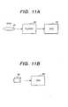
- Figs.11A and 11Bare block diagrams showing the recording/reproduction apparatus based on an embodiment of this invention.
- a recording mediume.g., a disk 31
- the disk 31is driven for reproducing by the video player 32. Unless copying is inhibited by the electronic watermark information, the video signal recorded on the disk 31 can be transferred for recording to the VCR 33.
- Fig.11Bshows the reproducing of the tape 34 by using the VCR 33.
- the VCR 33reproduces the record on the tape 34 only when the tape 34 is a legal duplication.
- Electronic watermark informationis used conceivably in two ways. One is to verify as to whether or not a disk is a legal duplication, and the other is to verify as to whether or not a tape has a legal copy of record produced by a VCR.
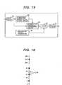
- Fig.12is a block diagram of the reproduction apparatus based on an embodiment of this invention.
- the apparatusincludes a disk reproducing mechanism 40, a signal processing circuit 41 which processes the reproduced signal, an output control circuit 42 which controls the transfer of the reproduction output to the player output terminal, and an electronic watermark information detecting circuit 43.
- Information recorded on the diskis reproduced by the reproducing mechanism 40 and fed to the signal processing circuit 41. If electronic watermark information based on CGMS (Copy Generation Management System) or SCMS (Serial Copy Management System) for example is recorded on the disk, it is read out and fed to the electronic watermark information detecting circuit 43.
- the detecting circuit 43decodes the watermark information and gives the decoded result to the output control circuit 42.
- the output control circuit 42controls the delivery of the reproduction output in accordance with the watermark information.
- the output control circuit 42blocks the reproduction output.
- the detecting circuit 43gives its copy inhibition output to the signal processing circuit 41 thereby to halt the operation of the circuit 41.
- the electronic watermark information based on CGMSis 2-bit information, and it is designed to indicate copy-enabled, one-copy-enabled, or copy-inhibited.
- the electronic watermark information based on SCMSis designed to indicate copy-enabled or copy-inhibited.
- the electronic watermark information detecting circuit 43is involved in such a problem that the video signal or information is distorted to have its amplitude varied during the passage through the transmission system and the watermark information embedded in the video signal or information is also varied in its amplitude and cannot be read out at the time of reproducing.
- the inventive method and apparatusare designed to insert a reference signal to the video signal (or information), as has been explained in connection with Fig.1 through Fig. 10. Based on this reference signal, the amplitude of the video signal in which the watermark information is embedded is corrected thereby to improve the accuracy of detection based on the arrangement shown in Fig. 12.
- Fig.13is a block diagram showing an embodiment of the reference signal detecting circuit included in the inventive reproduction apparatus.
- the video signal reproduced from the recording mediumis supplied to the sync detection circuit 50, by which the horizontal sync signal or vertical sync signal is detected.
- the watermark position detection pulse generating circuit 51In response to the sync signal detected by the sync detection circuit 50, the watermark position detection pulse generating circuit 51 generates a pulse which is used to detect the position of watermark information.
- the sync signalis also used by the reference signal position detection pulse generating circuit 52 to generate a pulse which is used to detect the position of a reference signal which is recorded by being inserted in the video signal (refer to Fig.1 through Fig.10 and the related explanation).
- the position detection pulse generated by the reference signal position detection pulse generating circuit 52is supplied to the sample-holding circuit 53 which samples and holds the reference signal level.
- the sample-holding circuit 53is further supplied with the video signal, and it samples and holds the amplitude of the reference signal inserted in the video signal in response to the position detection pulse.
- the sampled amplitude of the reference signalis supplied to the gain drift calculating circuit 54.
- the gain drift calculating circuit 54is designed to calculate the variation of reference signal amplitude, i.e., the variation of the gain of the luminance signal, caused by the transmission system, from the predetermined amplitude of the recorded reference signal.
- the gain drift of luminance signal calculated by the gain drift calculating circuit 54is indicated to the gain modifying circuit 55.
- the gain modifying circuit 55which is supplied with the video signal, modifies the gain of the luminance signal of the video signal.
- the video signalwith its luminance gain being modified, is supplied to the information detecting circuit 56, by which the electronic watermark information is detected in response to the pulse supplied from the watermark position detection pulse generating circuit 51.
- the gain variation of luminance signal caused by the timing signalis calculated from the level (amplitude) of the reference signal included in the reproduced signal, and the gain of luminance signal of the video signal is modified based on the calculation result for the detection of the electronic watermark information.
- Fig.14is a block diagram showing another embodiment of the reference signal detecting circuit included in the inventive reproduction apparatus.
- the output of the gain drift calculating circuit 54 and the video signalmay be supplied directly to the watermark information detecting circuit 56 so that the watermark information is detected and the luminance gain of the detected information is modified based on the calculation result of the gain drift calculating circuit 54, instead of modifying the gain of luminance signal by the gain modifying circuit 55 in the embodiment shown in Fig.13.
- a timing signal detecting circuit 57may be provided to detect the timing signals T1, T2 and T3 of Fig.6 so that the sample-holding circuit 53 samples and holds the amplitude of reference signal by using these timing signals.
- the reference signalmay be recorded by being inserted at a predetermined position, as shown in Fig. 6, relative to the sync signal so that the timing of reproduction of electronic watermark information can be modified and the watermark information can be detected more easily.
- Fig.15is a block diagram of the electronic watermark information recording apparatus based on an embodiment of this invention. This embodiment is designed to embed electronic watermark information by varying the luminance of pixels.
- a video signalis fed to the input circuit 61, which extracts the luminance signal from the video signal.
- the luminance signalis supplied to the permissible alteration range calculating circuit 63, which calculates depending on the luminance signal the alteration range of luminance signal which does not impose a significant visual drawback.
- the calculating circuit 63calculates the alteration range in consideration of the fact that the visual luminance does not much vary even for a large variation of luminance signal in picture portions having a large luminance variation, while the luminance variation is much visually noticeable in response to the variation of luminance signal in picture portions having a small luminance variation.
- the permissible alteration range calculating circuit 63can be accomplished by means of a CPU of a computer.
- the calculation result of the circuit 63is given to the information embedment processing circuit 65, which implements the process of embedding the electronic watermark information in the video signal by altering the luminance of the video signal when the luminance level is within the permissible alteration range.
- the video signal, with the electronic watermark information being embedded therein based on the alteration of luminance signal,is held in the memory of the output circuit 67 until the end of process for one frame of picture, and thereafter it is released from the memory.
- the calculation process by the permissible alteration range calculating circuit 63is implemented based on the following.
- the permissible alteration range calculating circuit 63memorizes the luminance before and after the image processing for each pixel, verifies as to whether or not the altered luminance is within the permissible alteration range, and alters the luminance signal only if it is within the permissible alteration range.
- the information embedment processing circuit 65initially selects pixels to be rendered the luminance alteration among all pixels of the picture. Subsequently, the circuit 65 embeds the information by altering the luminance to specific values for the selected pixels having the luminance within the permissible alteration range. As a result, a video signal, with the electronic watermark information being embedded therein, is produced, and it is released to the outside by way of the output circuit 67.
- the circuit arrangement of Fig.15further includes a reference signal generating circuit 68.
- the reference signal generated by the circuit 68is supplied to the adder 69, by which the signal is added to the video signal in which the electronic watermark information provided by the information embedment processing circuit 65 is embedded, and the resulting signal is recorded by way of the output circuit 67 onto the recording medium (not shown).
- Fig.16is a schematic diagram showing along a line the luminous values of pixels.
- the luminous value of a pixelis assumed to range from 0 to 255.
- a plain circle on the linerepresents embedded information "0" of a luminous value which is a multiple of 16
- a filled circlerepresents embedded information "1" of a luminous value which is a multiple of 16 added by 8.
- the basic operation of the information embedment processing circuit 65will be explained first.
- information of "0" to be embedded in a pixelis altered to a plain circle
- information of "1"is altered to a filled circle.
- the pixelhas its luminous value altered to 32 in case the information to be embedded is "0" or altered to 24 in case the information is "1".
- the usage of the permissible alteration range calculating circuit 63will be explained.
- the pictureoccasionally varies visually due to excessive alteration of the luminance of pixels.
- it is necessary to alter the pixel value within the permissible alteration rangeFor example, in case a pixel ⁇ has luminous value 30 and has a permissible luminance alteration range of 26-33 as shown in Fig.16, the pixel can have its luminance varied to 32 in accordance with the foregoing basic operation when the information to be embedded is "0".
- the target luminance 24is outside the permissible alteration range and therefore the luminance value is altered to 26 that is closest to 24, or alternatively this pixel is left unchanged and other predetermined pixel is treated for luminance alteration.
- the pixels having varied luminous valuesare selected based on their predetermined positions by use of pulses derived from the horizontal sync signal. Namely, these pixels having varied luminous values are selected based on the same rule as for the pixel selection by the information embedment processing circuit 65.
- the luminance signal of each selected pixelis taken out to determine as to whether the embedded information is "0" or "1" depending on whether the luminous value is closer to a multiple of 16 or a multiple of 16 added by 8.
- the information embedment processing circuit 65will not occasionally be able to alter the luminance exactly to a multiple of 16 or a multiple of 16 added by 8. Therefore, there will arise errors at a certain probability in information extraction. This problem, however, can be overcome by embedding the same information in multiple pixels and extracting the information based on the majority decision.
- the inventive method and apparatusimplements this modification by using a reference signal which is recorded in advance in the video signal, as shown in Fig.17.
- Fig.17is a schematic diagram showing the affair of luminance modification based on this invention.
- Indicated by 70 and 71 in the figureare positions of luminous values of the reference signal recorded in the video signal. These positions are of the first and second luminous values of the reference signal explained in connection with Fig.6.
- Another position 72is of luminous value 128 of the electronic watermark information resulting from the alteration of luminous value of the predetermined pixel.
- the luminous level of the electronic watermark information embedded in the luminance signalalso falls as shown in Fig.17, and the luminous value moves to position 72a.
- the luminous values of the reference signalhave their positions 70 and 71 moving to positions 70a and 71a. Based on the known luminous value 256 and the luminous value of reference signal, the luminous value of the position 72a can be altered to take the position 72.
- the inventive method and apparatusare capable of correcting the luminance level on the part of reproduction based on the reference signal recorded in the video signal, whereby the electronic watermark information can be detected efficiently.
- the luminance level of the watermark informationcan be corrected based on the reference signal recorded at a different position, and consequently the electronic watermark information can be detected more accurately.
Landscapes
- Engineering & Computer Science (AREA)
- Signal Processing (AREA)
- Multimedia (AREA)
- Physics & Mathematics (AREA)
- General Physics & Mathematics (AREA)
- Theoretical Computer Science (AREA)
- Computer Security & Cryptography (AREA)
- Television Signal Processing For Recording (AREA)
- Editing Of Facsimile Originals (AREA)
- Signal Processing For Digital Recording And Reproducing (AREA)
- Television Systems (AREA)
Description
- The present invention relates to a method for recording and reproducing image data, particularly electronic watermark information embedded (hidden) in video signals, which is used for the picture recording and reproduction control or for marking the origins of the records.
- Among the several schemes proposed for embedding electronic watermark information in video signals, representative one is described in the article entitled "Data Hiding Technique" in publication ITE Technical Report, Vol.21, No.31, pp.3-8. Another conventional information embedding technique is described in publication Nikkei Electronics, No.683, pp.99-107, published in 1997. These conventional techniques are intended to embed, in a video signal, information that is different in terms of statistical characteristics of image from the inherent picture information carried by the video signal, and use the embedded information at the time of picture reproduction for identifying the origin of the record or producing a control signal which enables or disable the reproducing of the video signal.
- However, these publications mainly describe recording means and do not describe the details of means of detecting electronic watermark information at the time of reproducing. Electronic watermark information recorded by a VCR or optical disk unit has its reproduced signal level varied depending on the reproduction characteristics of these apparatus. The reproduced signal waveform of the electronic watermark information varies also depending on the frequency characteristics of these apparatus.
- An aim of the present invention is to provide a method for recording and reproducing electronic watermark information which enables easy detection of the watermark information at the time of reproducing.
- Another aim of the present invention is to provide a method for recording and reproducing electronic watermark information which enables easy reproduction of the embedded electronic watermark information even if the reproduction characteristics of the reproduction apparatus vary.
- Still another aim of the present invention is to provide a method for recording and reproducing electronic watermark information which enables easy reproduction of the electronic watermark information even if the signal level of the watermark information varies.
- In order to achieve the above aims, the present invention teaches a method of recording a video signal, electronic watermark information which is embedded in the video signal and a reference signal which is inserted at a position different from the position of the watermark information in the video signal.
- Thus, the present invention provides a method of recording electronic watermark information as set out in
claim 1. The method may also include detecting or reproducing the reference signal, and modifying the watermark information based on the reference signal. - Preferably, the watermark information is derived from the luminance signal included in a video signal, with the luminous value of the luminance signal being altered at a predetermined position within the calculated alteration range.
- In another aspect, the present invention provides a method of reproducing electronic watermark information according to
claim 9. - The inventive method is designed to append preparatorily a reference signal used for the detection of electronic watermark information at a specific position of a video signal and reproduce the watermark information based on this reference signal at the time of reproducing. The reference signal is embedded within the period of horizontal sync signal outside the picture display period, i.e., in the back-porch or front-porch portion, or outside the picture display area. At the time of detection, the embedded electronic watermark information is reproduced based on the reference signal level.
- Alternatively, the reference signal may be recorded within the period of vertical sync signal. A reference timing signal is recorded at the head of the video signal so that the recording level and recording position of the electronic watermark information are detected based on the reference signal level and reproduction timing at the time of reproducing.
- These and other objects, features and advantages of the invention will be apparent from the following more particular description of preferred embodiments of the invention, as illustrated in the accompanying drawings.
- Fig.1 is a schematic diagram showing the reference signal and the recording position thereof used by the method and apparatus for recording and reproducing electronic watermark information and the recording medium based on an embodiment of this invention;
- Fig.2 is a schematic diagram showing the reference signals and the recording position thereof used by the method and apparatus for recording and reproducing electronic watermark information and the recording medium based on another embodiment of this invention;
- Fig.3 is a schematic diagram showing the reference signals and the recording position thereof used by the method and apparatus for recording and reproducing electronic watermark information and the recording medium based on still another embodiment of this invention;
- Fig.4 is a schematic diagram showing the reference signals and the recording position thereof used by the method and apparatus for recording and reproducing electronic watermark information and the recording medium based on still another embodiment of this invention;
- Fig.5 is a schematic diagram showing the reference signals and the recording position thereof used by the method and apparatus for recording and reproducing electronic watermark information and the recording medium based on still another embodiment of this invention;
- Figs. 6A, 6B and 6C are waveform diagrams showing the first, second and third reference signals shown in Fig. 5, the timing signal, and the sampled-and-held reference signals based on an embodiment of this invention;
- Fig.7 is a schematic diagram showing the reference signal and the recording position thereof used by the method and apparatus for recording and reproducing electronic watermark information and the recording medium based on still another embodiment of this invention;
- Fig.8 is a schematic diagram showing the reference signal and the recording position thereof used by the method and apparatus for recording and reproducing electronic watermark information and the recording medium based on still another embodiment of this invention;
- Fig.9 is a schematic diagram showing the positional relation among the reference signal shown in Fig.7, the horizontal sync period, the picture display area and the over-scan area;
- Fig.10 is a schematic diagram showing the positional relation among the reference signal shown in Fig.8, the horizontal sync period, the picture display area and the over-scan area;
- Figs.11A and 11B are block diagrams of the electronic watermark information reproduction apparatus based on an embodiment of this invention;
- Fig.12 is a block diagram of the electronic watermark information reproduction apparatus based on an embodiment of this invention;
- Fig.13 is a block diagram showing an embodiment of the reference signal detecting circuit in the electronic watermark information reproduction apparatus of this invention;
- Fig.14 is a block diagram showing another embodiment of the reference signal detecting circuit in the electronic watermark information reproduction apparatus of this invention;
- Fig.15 is a block diagram of the electronic watermark information recording apparatus based on an embodiment of this invention;
- Fig. 16 is a schematic diagram showing the linear display of luminous values of pixels; and
- Fig.17 is a schematic diagram showing the modification of luminance based on this invention.
- The method and apparatus for recording and reproducing electronic watermark information and the recording medium based on this invention will be explained with reference to the drawings.
- Fig.1 is a schematic diagram showing the reference signal and the recording position thereof used by the method and apparatus for recording and reproducing electronic watermark information based on an embodiment of this invention. In the figure,
numeral 1 denotes the picture display area of a display apparatus such as a television receiver, 2 is the over-scan area which is the remaining portion of the area enclosed by the dashed lines excluding thepicture display area area 2. - The reference signal which takes up one or more lines is inserted or added to a video signal. The video signal, with the reference signal being appended thereto, is recorded on a recording medium. The reference signal is included in the video signal so that it is located preferably in the over-scan area, instead of the
picture display area 1 in which case the video signal would possibily be disturbed. - Fig.2 is a schematic diagram showing the reference signals and the recording position thereof used by the method and apparatus for recording and reproducing electronic watermark information and the recording medium based on another embodiment of this invention. In the figure,
reference signals signals - Generally, TV signals are liable to sag at the top and bottom of the screen due to the influence of the transmission system. Specifically, when a TV signal for producing a constant luminance over the entire screen is transmitted, it varies due to the influence of the transmission system, resulting in a varied displayed luminance at the top and bottom of the screen. This phenomenon is pronounced particularly in gray colors.
- This phenomenon can possibly cause the luminance of electronic watermark information to vary in an asymmetric fashion. The embodiment of Fig.2 is intended to correct the luminance variation by inserting the
reference signals reference signal 4 for the top of the screen and thereference signal 5 for the bottom of the screen. Alternatively, the mean value of the upper andlower reference signals - Fig.3 is a schematic diagram showing the reference signals and the recording position thereof used by the method and apparatus for recording and reproducing electronic watermark information and the recording medium based on still another embodiment of this invention.
- In this embodiment,
reference signals area 2. Thereference signals signals area 2, instead of inserting thereference signals area 2. In the case of a VCR, the head is switched at the lower side of the tape, allowing of less space for thereference signal 7, and therefore it is advantageous to adopt thereference signal 6 in the larger area of the upper side of the tape. - The
reference signals reference signals reference signals - Fig.4 is a schematic diagram showing the reference signals and the recording position thereof used by the method and apparatus for recording and reproducing electronic watermark information and the recording medium based on still another embodiment of this invention.
- Shown in Fig.4 is an example in which
reference signals area 2 immediately before and after the horizontal sync signals. Namely, the reference signals 8 and 9 are added to the video signal by being recorded at the beginning and end of the horizontal sync period. Alternatively, a reference signal may be inserted only at the head or end of the horizontal sync signal for correcting the luminance level of the video signal, instead of adding the reference signals 8 and 9 at the beginning and end of the horizontal sync period. - Fig.5 is a schematic diagram showing the reference signals and the recording position thereof used by the method and apparatus for recording and reproducing electronic watermark information and the recording medium based on still another embodiment of this invention. In this embodiment, a first, second and third reference signals 11,12 and 13 having different luminance levels are inserted to locate in the
over-scan area 2. Each of the reference signals 11,12 and 13 may be a line, instead of a block shown in Fig.5. - Figs.6A,6B and 6C are waveform diagrams of the first, second and third reference signals shown in Fig.5, the timing signal, and the sampled-and-held reference signals based on an embodiment of this invention. Fig.6A shows the waveform of the first, second and third reference signals 11,12 and 13, which are inserted between the horizontal sync signals 15 and 16 in the
over-scan area 2. - These reference signals 11,12 and 13 have different levels. For example, the
first reference signal 11 has a level equal to the peak white level (IRE 100), thesecond reference signal 12 has a level equal to half the peak white level (IRE 50), and thethird reference signal 13 has the level of IRE-10. - Fig.6B shows the waveform of the timing pulse, which provides timing signals T1, T2 and T3 for sampling the first, second and third reference signals 11 ,12 and 13, respectively. The timing signals T1, T2 and T3 are generated at predetermined time points by being timed to the
horizontal sync signal 15. The first, second and third reference signals 11,12 and 13 are sampled and held in response to the timing signals T1, T2 and T3, respectively. - The timing signals T1, T2 and T3 may be added at the head of the video signal, in which case the signals can be used as timing signals for the detection of electronic watermark information and can also be used as a signal for modifying the timing signals which are produced from the sync signal.
- Fig.6C shows the waveforms of the first, second and third sampled-and-held reference signals 11a, 12a and 13a having levels A1, A2 and A3, respectively. Using these reference signals 11a, 12a and 13a having the different levels enables the discrimination as to whether the variation of luminance level of the reference signals 11a,12a and 13a is the linear type or nonlinear type. In case the luminance varies at a constant rate irrespective of the luminance level, i.e., linear variation, it is possible to correct the luminance of the video signal at the position where electronic watermark information is embedded by using one of the first, second and third reference signals 11a, 12a and 13a. In another case of a different variation rate of luminance level depending on the reference signal, i.e., nonlinear variation of luminance level, a luminance variation rate for the luminance level is evaluated approximately from the levels of the first, second and third reference signals 11a,12a and 13a and the luminance of electronic watermark information is corrected depending on the luminance level of the electronic watermark information to be detected. In this manner, the luminance of electronic watermark information can be corrected accurately.
- By making the inserting positions of the first, second and third reference signals 11,12 and 13 synchronous with the position where electronic watermark information is recorded, a reference clock is produced based on the timing signals T1, T2 and T3, and the recording position of the watermark information can be detected based on the clock.
- Electronic watermark information is embedded in a block of 8-by-8 pixels at a predetermined position, as described in the prior art publications. For extracting the electronic watermark information at the time of reproducing, it is crucial to make accurate synchronization with the block. By making the timing signals T1, T2 and T3 synchronous with the position of embedment of electronic watermark information and recording the timing signals in synchronism with the 8-by-8 pixel block at recording, it becomes possible to minimize the influence of the phase variation of the timing signals in the transmission system.
- The first, second and third reference level signals 11, 12 and 13 which have been extracted together with the watermark information are latched by the sample-holding circuit, and used to detect the watermark information embedded in the video signal, so that the influence of the luminance variation by the transmission system can be corrected.
- Fig. 7 is a schematic diagram showing the reference signal and the recording position thereof used by the method and apparatus for recording and reproducing electronic watermark information and the recording medium based on still another embodiment of this invention. In the figure, a
reference signal 21 is inserted in the horizontal blanking period outside theover-scan area 2, and it is considered to be located at the top-right position seen from the screen as shown. - Fig. 8 is a schematic diagram showing the reference signal and the recording position thereof used by the method and apparatus for recording and reproducing electronic watermark information and the recording medium based on still another embodiment of this invention. In the figure, a
reference signal 22 is inserted in the vertical blanking period outside of theover-scan area 2, and it is considered to be located at the bottom-right position seen from the screen as shown. - Fig.9 is a schematic diagram showing the positional relation among the reference signal shown in Fig.7, the horizontal sync period, the picture display area and the over-scan area. Fig.10 is a schematic diagram showing the positional relation among the reference signal shown in Fig. 8, the vertical sync period, the picture display area and the over-scan area.
- As shown in Fig. 9, a horizontal sync period P1 is divided into a video signal period P2, horizontal flyback periods P3 and P4, and a sync signal period P5. The video signal period P2 is further divided into a picture display period P6 and over-scan periods P7 and P8. The video signal period P2 is usually set wider than the screen width P6 so that it completely covers the screen width.
- In this embodiment, the
reference signal 21 is recorded to locate outside of the picture display period P6. Indicated by 15 and 16 in Fig.9 are horizontal sync signals, and 23 is a video signal. - The
reference signal 21 may be located before the video signal 23 without any problem, instead of being located after the video signal 23 shown in the figure. - Fig.10 is a schematic diagram showing the positional relation among the reference signal shown in Fig.8, the vertical sync period, the picture display area and the over-scan area. As shown in Fig.10, a vertical sync period P11 is divided into a video signal period P12, vertical flyback periods P13 and P14, and vertical sync signal period P15. The video signal period P12 is further divided into a picture display period P16 and over-scan periods P17 and P18. The video signal period P12 is usually set greater than the screen height P16 so that it completely covers the screen height.
- In this embodiment, the
reference signal 22 is recorded to locate outside of the video signal period P12. Indicated by 25 and 26 in Fig.10 are vertical sync signals, and 27 is a video signal between the vertical sync signals 25 and 26. - Next, the arrangement for reproduction based on the processing of information recorded on the recording medium, with electronic watermark information being embedded in it, will be explained with reference to Figs.11A and 11B, Fig.12 and Fig.13.
- Figs.11A and 11B are block diagrams showing the recording/reproduction apparatus based on an embodiment of this invention. In Fig.11A, a recording medium, e.g., a
disk 31, has a record of a video signal, electronic watermark information embedded in the video signal and a reference signal for correcting the amplitude variation at the reproduction of the watermark information. Thedisk 31 is driven for reproducing by thevideo player 32. Unless copying is inhibited by the electronic watermark information, the video signal recorded on thedisk 31 can be transferred for recording to theVCR 33. - Fig.11B shows the reproducing of the
tape 34 by using theVCR 33. TheVCR 33 reproduces the record on thetape 34 only when thetape 34 is a legal duplication. - Electronic watermark information is used conceivably in two ways. One is to verify as to whether or not a disk is a legal duplication, and the other is to verify as to whether or not a tape has a legal copy of record produced by a VCR.
- When a disk, with electronic watermark information being recorded, is driven for reproducing by a proper player, the player first reads the watermark information to verify the legality of the disk and proceeds to the reproducing operation, as will be explained in the following.
- Fig.12 is a block diagram of the reproduction apparatus based on an embodiment of this invention. The apparatus includes a
disk reproducing mechanism 40, asignal processing circuit 41 which processes the reproduced signal, anoutput control circuit 42 which controls the transfer of the reproduction output to the player output terminal, and an electronic watermarkinformation detecting circuit 43. - Information recorded on the disk is reproduced by the reproducing
mechanism 40 and fed to thesignal processing circuit 41. If electronic watermark information based on CGMS (Copy Generation Management System) or SCMS (Serial Copy Management System) for example is recorded on the disk, it is read out and fed to the electronic watermarkinformation detecting circuit 43. The detectingcircuit 43 decodes the watermark information and gives the decoded result to theoutput control circuit 42. - The
output control circuit 42 controls the delivery of the reproduction output in accordance with the watermark information. In case the detectingcircuit 43 has detected the copy inhibition in the watermark information, theoutput control circuit 42 blocks the reproduction output. Alternatively, the detectingcircuit 43 gives its copy inhibition output to thesignal processing circuit 41 thereby to halt the operation of thecircuit 41. - The electronic watermark information based on CGMS is 2-bit information, and it is designed to indicate copy-enabled, one-copy-enabled, or copy-inhibited. The electronic watermark information based on SCMS is designed to indicate copy-enabled or copy-inhibited.
- The electronic watermark
information detecting circuit 43 is involved in such a problem that the video signal or information is distorted to have its amplitude varied during the passage through the transmission system and the watermark information embedded in the video signal or information is also varied in its amplitude and cannot be read out at the time of reproducing. - In order to overcome this problem, the inventive method and apparatus are designed to insert a reference signal to the video signal (or information), as has been explained in connection with Fig.1 through Fig. 10. Based on this reference signal, the amplitude of the video signal in which the watermark information is embedded is corrected thereby to improve the accuracy of detection based on the arrangement shown in Fig. 12.
- The following explains with reference to Fig.13 as an example the improvement of detection accuracy of the detecting circuit based on the manipulation of the detecting circuit in response to a reference signal which is embedded in a predetermined position of the video signal.
- Fig.13 is a block diagram showing an embodiment of the reference signal detecting circuit included in the inventive reproduction apparatus. In the figure, the video signal reproduced from the recording medium is supplied to the
sync detection circuit 50, by which the horizontal sync signal or vertical sync signal is detected. In response to the sync signal detected by thesync detection circuit 50, the watermark position detectionpulse generating circuit 51 generates a pulse which is used to detect the position of watermark information. The sync signal is also used by the reference signal position detectionpulse generating circuit 52 to generate a pulse which is used to detect the position of a reference signal which is recorded by being inserted in the video signal (refer to Fig.1 through Fig.10 and the related explanation). - The position detection pulse generated by the reference signal position detection
pulse generating circuit 52 is supplied to the sample-holdingcircuit 53 which samples and holds the reference signal level. The sample-holdingcircuit 53 is further supplied with the video signal, and it samples and holds the amplitude of the reference signal inserted in the video signal in response to the position detection pulse. The sampled amplitude of the reference signal is supplied to the gaindrift calculating circuit 54. - The gain
drift calculating circuit 54 is designed to calculate the variation of reference signal amplitude, i.e., the variation of the gain of the luminance signal, caused by the transmission system, from the predetermined amplitude of the recorded reference signal. The gain drift of luminance signal calculated by the gaindrift calculating circuit 54 is indicated to thegain modifying circuit 55. - The
gain modifying circuit 55, which is supplied with the video signal, modifies the gain of the luminance signal of the video signal. The video signal, with its luminance gain being modified, is supplied to theinformation detecting circuit 56, by which the electronic watermark information is detected in response to the pulse supplied from the watermark position detectionpulse generating circuit 51. - In this embodiment, the gain variation of luminance signal caused by the timing signal is calculated from the level (amplitude) of the reference signal included in the reproduced signal, and the gain of luminance signal of the video signal is modified based on the calculation result for the detection of the electronic watermark information. By correcting the level variation of the luminance signal caused by the transmission system by using the reference signal which is also distorted, it becomes possible to reproduce the watermark information by eliminating or reducing the influence of the level variation of the luminance signal caused by the transmission system.
- Fig.14 is a block diagram showing another embodiment of the reference signal detecting circuit included in the inventive reproduction apparatus. As shown in this figure, the output of the gain
drift calculating circuit 54 and the video signal may be supplied directly to the watermarkinformation detecting circuit 56 so that the watermark information is detected and the luminance gain of the detected information is modified based on the calculation result of the gaindrift calculating circuit 54, instead of modifying the gain of luminance signal by thegain modifying circuit 55 in the embodiment shown in Fig.13. - In place of the circuit for detecting the position of reference signal from the sync signal, a timing
signal detecting circuit 57 may be provided to detect the timing signals T1, T2 and T3 of Fig.6 so that the sample-holdingcircuit 53 samples and holds the amplitude of reference signal by using these timing signals. - Instead of dealing with the reference signal level as explained above, the reference signal may be recorded by being inserted at a predetermined position, as shown in Fig. 6, relative to the sync signal so that the timing of reproduction of electronic watermark information can be modified and the watermark information can be detected more easily.
- Fig.15 is a block diagram of the electronic watermark information recording apparatus based on an embodiment of this invention. This embodiment is designed to embed electronic watermark information by varying the luminance of pixels.
- In Fig. 15, a video signal is fed to the
input circuit 61, which extracts the luminance signal from the video signal. The luminance signal is supplied to the permissible alterationrange calculating circuit 63, which calculates depending on the luminance signal the alteration range of luminance signal which does not impose a significant visual drawback. Specifically, the calculatingcircuit 63 calculates the alteration range in consideration of the fact that the visual luminance does not much vary even for a large variation of luminance signal in picture portions having a large luminance variation, while the luminance variation is much visually noticeable in response to the variation of luminance signal in picture portions having a small luminance variation. - The permissible alteration
range calculating circuit 63 can be accomplished by means of a CPU of a computer. The calculation result of thecircuit 63 is given to the informationembedment processing circuit 65, which implements the process of embedding the electronic watermark information in the video signal by altering the luminance of the video signal when the luminance level is within the permissible alteration range. The video signal, with the electronic watermark information being embedded therein based on the alteration of luminance signal, is held in the memory of theoutput circuit 67 until the end of process for one frame of picture, and thereafter it is released from the memory. - The calculation process by the permissible alteration
range calculating circuit 63 is implemented based on the following. - (1) At a picture portion where the variation of edge is great, the picture does not much vary visually even for a large variation of amplitude of the edge signal, whereas at a picture portion where the edge variation is small, the picture visually varies significantly when the amplitude of edge signal is altered greatly.
- (2) The alteration range of picture is limited to the range in which the picture does not vary visually, or to the range in which the visual variation of picture does not cause the discomfort of viewers.
- Based on the embedment of electronic watermark information in this manner in terms of luminance different from the original picture, the resulting picture does not vary in a visual sense. The permissible alteration
range calculating circuit 63 memorizes the luminance before and after the image processing for each pixel, verifies as to whether or not the altered luminance is within the permissible alteration range, and alters the luminance signal only if it is within the permissible alteration range. - The information
embedment processing circuit 65 initially selects pixels to be rendered the luminance alteration among all pixels of the picture. Subsequently, thecircuit 65 embeds the information by altering the luminance to specific values for the selected pixels having the luminance within the permissible alteration range. As a result, a video signal, with the electronic watermark information being embedded therein, is produced, and it is released to the outside by way of theoutput circuit 67. - The circuit arrangement of Fig.15 further includes a reference
signal generating circuit 68. The reference signal generated by thecircuit 68 is supplied to theadder 69, by which the signal is added to the video signal in which the electronic watermark information provided by the informationembedment processing circuit 65 is embedded, and the resulting signal is recorded by way of theoutput circuit 67 onto the recording medium (not shown). - Next, the alteration of luminance by the information
embedment processing circuit 65 will be explained with reference to Fig.16. - Fig.16 is a schematic diagram showing along a line the luminous values of pixels. The luminous value of a pixel is assumed to range from 0 to 255. In the figure, a plain circle on the line represents embedded information "0" of a luminous value which is a multiple of 16, while a filled circle represents embedded information "1" of a luminous value which is a multiple of 16 added by 8.
- The basic operation of the information
embedment processing circuit 65 will be explained first. For obtaining the electronic watermark information, it is necessary to alter the luminance of a pixel of the picture to the closest plain circle or filled circle. Specifically, information of "0" to be embedded in a pixel is altered to a plain circle, while information of "1" is altered to a filled circle. For example, forluminous value 30 of a pixel indicated by Δ in the figure, the pixel has its luminous value altered to 32 in case the information to be embedded is "0" or altered to 24 in case the information is "1". - Next, the usage of the permissible alteration
range calculating circuit 63 will be explained. In embedding the electronic watermark information, the picture occasionally varies visually due to excessive alteration of the luminance of pixels. For preventing this impropriety, it is necessary to alter the pixel value within the permissible alteration range. For example, in case a pixel Δ hasluminous value 30 and has a permissible luminance alteration range of 26-33 as shown in Fig.16, the pixel can have its luminance varied to 32 in accordance with the foregoing basic operation when the information to be embedded is "0". Whereas, in case the information to be embedded is "1", thetarget luminance 24 is outside the permissible alteration range and therefore the luminance value is altered to 26 that is closest to 24, or alternatively this pixel is left unchanged and other predetermined pixel is treated for luminance alteration. - The manner of extracting the electronic watermark information from the video signal will be explained. Initially, the pixels having varied luminous values are selected based on their predetermined positions by use of pulses derived from the horizontal sync signal. Namely, these pixels having varied luminous values are selected based on the same rule as for the pixel selection by the information
embedment processing circuit 65. - Subsequently, the luminance signal of each selected pixel is taken out to determine as to whether the embedded information is "0" or "1" depending on whether the luminous value is closer to a multiple of 16 or a multiple of 16 added by 8.
- Because of luminance alteration within the permissible alteration range, the information
embedment processing circuit 65 will not occasionally be able to alter the luminance exactly to a multiple of 16 or a multiple of 16 added by 8. Therefore, there will arise errors at a certain probability in information extraction. This problem, however, can be overcome by embedding the same information in multiple pixels and extracting the information based on the majority decision. - In detecting the recorded electronic watermark information, it is crucial to modify the level variation of luminance signal. On this account, the inventive method and apparatus implements this modification by using a reference signal which is recorded in advance in the video signal, as shown in Fig.17.
- Fig.17 is a schematic diagram showing the affair of luminance modification based on this invention. Indicated by 70 and 71 in the figure are positions of luminous values of the reference signal recorded in the video signal. These positions are of the first and second luminous values of the reference signal explained in connection with Fig.6. Another
position 72 is ofluminous value 128 of the electronic watermark information resulting from the alteration of luminous value of the predetermined pixel. - When the amplitude of the luminance signal included in the video signal decreases, the luminous level of the electronic watermark information embedded in the luminance signal also falls as shown in Fig.17, and the luminous value moves to position 72a. Similarly, the luminous values of the reference signal have their
positions positions luminous value 256 and the luminous value of reference signal, the luminous value of theposition 72a can be altered to take theposition 72. - Detection of electronic watermark information on the part of reproduction at the same level as the part of recording will occasionally fail due to the level variation. Whereas, the inventive method and apparatus are capable of correcting the luminance level on the part of reproduction based on the reference signal recorded in the video signal, whereby the electronic watermark information can be detected efficiently.
- According to the present invention, even if the electronic watermark information recorded in the video signal is distorted by the transmission system, the luminance level of the watermark information can be corrected based on the reference signal recorded at a different position, and consequently the electronic watermark information can be detected more accurately.
Claims (10)
- A method of recording electronic watermark information comprising the steps of:embedding electronic watermark information in a video signal at a minimal disturbance against said video signal; andrecording a reference signal which is inserted at a position different from the position of said electronic watermark information,wherein said reference signal is used to set a detection level used by a detector to detect said watermark information which has been embedded in said video signal.
- A method according to claim 1, wherein the insertion position of said reference signal is in the over-scan area of said video signal.
- A method according to claim 1, wherein the insertion position of said reference signal is in the blanking period of a sync signal.
- A method according to claim 1, wherein said reference signal has a amplitude equal to the peak white level.
- A method of recording electronic watermark information according to claim 1, wherein the reference signal includes a first reference signal and a second reference signal, the first reference signal having an amplitude equal to a peak white level, the second reference signal having an amplitude smaller than the amplitude of the first reference signal.
- A method of recording and reproducing electronic watermark information comprising:recording electronic watermark information according to the method of claim 1, andreproducing said reference signal and modifying said electronic watermark information by using said reference signal.
- A method according to claim 6, wherein said electronic watermark information is derived from a luminance signal, with the luminous value thereof being altered, at a predetermined position of said video signal.
- A method according to claim 6, wherein said modifying step modifies the luminous value of said electronic watermark information based on the luminous value of said reference signal.
- A method of reproducing electronic watermark information comprising the steps of:detecting a reference signal for detecting electronic watermark information from a recording medium on which a video signal, said electronic watermark information which is embedded in said video signal by the alteration of the luminous value of a luminance signal included in said video signal and said reference signal which is inserted at a position different from the position of embedment of said electronic watermark information are recorded,wherein said reference signal is used to set a detection level used during said detecting step to detect said watermark information which has been embedded in said video signal; andmodifying the luminous value of said electronic watermark information based on said reference signal.
- A method of reproducing electronic watermark information according to claim 9, wherein the modifying step includes the step of calculating a drop of a gain of the reference signal; and
wherein the detecting step includes the steps of generating an electronic watermark information position detection signal based on a sync signal, and
generating a reference signal potion detection signal based on a sync signal.
Applications Claiming Priority (3)
| Application Number | Priority Date | Filing Date | Title |
|---|---|---|---|
| JP23802997 | 1997-09-03 | ||
| JP238029/97 | 1997-09-03 | ||
| JP23802997 | 1997-09-03 |
Publications (3)
| Publication Number | Publication Date |
|---|---|
| EP0901282A2 EP0901282A2 (en) | 1999-03-10 |
| EP0901282A3 EP0901282A3 (en) | 2001-02-07 |
| EP0901282B1true EP0901282B1 (en) | 2006-06-28 |
Family
ID=17024119
Family Applications (1)
| Application Number | Title | Priority Date | Filing Date |
|---|---|---|---|
| EP98306484AExpired - LifetimeEP0901282B1 (en) | 1997-09-03 | 1998-08-14 | Method for recording and reproducing electronic watermark information |
Country Status (3)
| Country | Link |
|---|---|
| US (3) | US6535614B1 (en) |
| EP (1) | EP0901282B1 (en) |
| KR (1) | KR100349427B1 (en) |
Cited By (5)
| Publication number | Priority date | Publication date | Assignee | Title |
|---|---|---|---|---|
| US7197156B1 (en) | 1998-09-25 | 2007-03-27 | Digimarc Corporation | Method and apparatus for embedding auxiliary information within original data |
| US7333957B2 (en) | 1995-07-27 | 2008-02-19 | Digimarc Corporation | Connected audio and other media objects |
| US7373513B2 (en) | 1998-09-25 | 2008-05-13 | Digimarc Corporation | Transmarking of multimedia signals |
| US7489801B2 (en) | 2001-04-25 | 2009-02-10 | Digimarc Corporation | Encoding and decoding signals for digital watermarking |
| US7532740B2 (en) | 1998-09-25 | 2009-05-12 | Digimarc Corporation | Method and apparatus for embedding auxiliary information within original data |
Families Citing this family (41)
| Publication number | Priority date | Publication date | Assignee | Title |
|---|---|---|---|---|
| US6983051B1 (en) | 1993-11-18 | 2006-01-03 | Digimarc Corporation | Methods for audio watermarking and decoding |
| US6590996B1 (en)* | 2000-02-14 | 2003-07-08 | Digimarc Corporation | Color adaptive watermarking |
| US7006661B2 (en)* | 1995-07-27 | 2006-02-28 | Digimarc Corp | Digital watermarking systems and methods |
| US7003731B1 (en)* | 1995-07-27 | 2006-02-21 | Digimare Corporation | User control and activation of watermark enabled objects |
| JP4064506B2 (en) | 1997-09-17 | 2008-03-19 | パイオニア株式会社 | Digital watermark superimposing method, detecting method and apparatus |
| US6263086B1 (en)* | 1998-04-15 | 2001-07-17 | Xerox Corporation | Automatic detection and retrieval of embedded invisible digital watermarks from halftone images |
| JP2000295454A (en)* | 1999-04-05 | 2000-10-20 | Hitachi Ltd | Electronic watermarking apparatus and method, and recording medium |
| US20010034705A1 (en)* | 1999-05-19 | 2001-10-25 | Rhoads Geoffrey B. | Payment-based systems for internet music |
| US6957768B1 (en)* | 1999-05-25 | 2005-10-25 | Silverbrook Research Pty Ltd | Computer system control via interface surface |
| US6456726B1 (en)* | 1999-10-26 | 2002-09-24 | Matsushita Electric Industrial Co., Ltd. | Methods and apparatus for multi-layer data hiding |
| US6344853B1 (en)* | 2000-01-06 | 2002-02-05 | Alcone Marketing Group | Method and apparatus for selecting, modifying and superimposing one image on another |
| US7127744B2 (en) | 2000-03-10 | 2006-10-24 | Digimarc Corporation | Method and apparatus to protect media existing in an insecure format |
| WO2001071960A1 (en)* | 2000-03-18 | 2001-09-27 | Digimarc Corporation | Transmarking, watermark embedding functions as rendering commands, and feature-based watermarking of multimedia signals |
| GB2360659A (en)* | 2000-03-20 | 2001-09-26 | British Broadcasting Corp | Watermarking in the luminance component of a picture signal |
| JP3630071B2 (en)* | 2000-04-05 | 2005-03-16 | 日本電気株式会社 | Digital watermark detector and digital watermark detection method used therefor |
| AU2002225593A1 (en) | 2000-10-17 | 2002-04-29 | Digimarc Corporation | User control and activation of watermark enabled objects |
| GB2377108B (en)* | 2001-06-28 | 2003-12-10 | Motorola Inc | Video/image communication with watermarking |
| KR100837839B1 (en)* | 2001-10-25 | 2008-06-13 | 주식회사 케이티 | Audio watermark rehabilitation apparatus and the method that is damaged by speed alteration attack |
| US6873744B2 (en)* | 2002-04-17 | 2005-03-29 | Regents Of The University Of Minnesota | Image restoration from transformed component data |
| US6775394B2 (en) | 2002-03-12 | 2004-08-10 | Matsushita Electric Industrial Co., Ltd. | Digital watermarking of binary document using halftoning |
| EP1514227B1 (en)* | 2002-05-14 | 2013-06-26 | Schreiner Group GmbH & Co. KG | Visible authentication patterns for printed document |
| US6782116B1 (en)* | 2002-11-04 | 2004-08-24 | Mediasec Technologies, Gmbh | Apparatus and methods for improving detection of watermarks in content that has undergone a lossy transformation |
| US7038669B2 (en)* | 2002-07-01 | 2006-05-02 | Hewlett-Packard Development Company, L.P. | System and method for providing a reference video signal |
| AU2003253184A1 (en)* | 2002-08-28 | 2004-03-19 | Koninklijke Philips Electronics N.V. | Method and arrangement for watermark detection |
| WO2004021275A2 (en)* | 2002-08-30 | 2004-03-11 | Koninklijke Philips Electronics N.V. | Embedding fingerprint data for media content identification |
| KR20040063379A (en)* | 2003-01-07 | 2004-07-14 | 삼성전자주식회사 | Picture adjustment method using video pattern and DVD player providing video pattern |
| US20040172548A1 (en)* | 2003-03-01 | 2004-09-02 | Anderson Daryl E. | Access permission based on optically readable marking on optical disc label region |
| US7590293B2 (en)* | 2003-05-05 | 2009-09-15 | Regents Of The University Of Minnesota | Non-iterative method to restore image from transformed component data |
| US8032754B2 (en)* | 2004-01-09 | 2011-10-04 | Microsoft Corporation | Systems and methods for embedding media forensic identification markings |
| JP4422515B2 (en)* | 2004-03-11 | 2010-02-24 | 日立オムロンターミナルソリューションズ株式会社 | Paper sheet identification device |
| JP4603446B2 (en)* | 2004-09-29 | 2010-12-22 | 株式会社リコー | Image processing apparatus, image processing method, and image processing program |
| CN102202204A (en)* | 2004-10-28 | 2011-09-28 | 罗威解决方案公司 | Device and method for modifying video signal |
| KR101298921B1 (en)* | 2005-04-04 | 2013-08-30 | 삼성디스플레이 주식회사 | Pre-subpixel rendered image processing in display systems |
| US7792293B2 (en)* | 2005-05-06 | 2010-09-07 | Rovi Solutions Corporation | Method and apparatus for modifying a subsequently generated control command in a content control system |
| JP2008118180A (en)* | 2006-10-31 | 2008-05-22 | Funai Electric Co Ltd | Standard image reading apparatus and standard image reading method using the same |
| US20080309816A1 (en)* | 2007-06-15 | 2008-12-18 | Macrovision Corporation | Television content control system and method with cross-platform capability |
| US8805689B2 (en)* | 2008-04-11 | 2014-08-12 | The Nielsen Company (Us), Llc | Methods and apparatus to generate and use content-aware watermarks |
| US20110066437A1 (en)* | 2009-01-26 | 2011-03-17 | Robert Luff | Methods and apparatus to monitor media exposure using content-aware watermarks |
| FR2957742B1 (en)* | 2010-03-22 | 2012-04-13 | Peugeot Citroen Automobiles Sa | METHODS AND DEVICES FOR GENERATING AND USING VIDEO IMAGES HAVING CONTROL MESSAGES |
| US10049002B2 (en)* | 2014-06-26 | 2018-08-14 | Intel Corporation | Display interface bandwidth modulation |
| US9912986B2 (en) | 2015-03-19 | 2018-03-06 | Sony Corporation | System for distributing metadata embedded in video |
Family Cites Families (139)
| Publication number | Priority date | Publication date | Assignee | Title |
|---|---|---|---|---|
| US3569619A (en) | 1968-06-27 | 1971-03-09 | Luther G Simjian | Verification system using coded identifying and storage means |
| US4944036A (en) | 1970-12-28 | 1990-07-24 | Hyatt Gilbert P | Signature filter system |
| DE2757171C3 (en) | 1977-12-22 | 1980-07-10 | Standard Elektrik Lorenz Ag, 7000 Stuttgart | Method and arrangement for the transmission of two different pieces of information in a single transmission channel with a given bandwidth on a carrier wave |
| US4230990C1 (en) | 1979-03-16 | 2002-04-09 | John G Lert Jr | Broadcast program identification method and system |
| US4367488A (en) | 1980-12-08 | 1983-01-04 | Sterling Television Presentations Inc. Video Data Systems Division | Data encoding for television |
| US4380027A (en) | 1980-12-08 | 1983-04-12 | William Leventer | Data encoding for television |
| US4425642A (en) | 1982-01-08 | 1984-01-10 | Applied Spectrum Technologies, Inc. | Simultaneous transmission of two information signals within a band-limited communications channel |
| US4908873A (en) | 1983-05-13 | 1990-03-13 | Philibert Alex C | Document reproduction security system |
| US4888798A (en) | 1985-04-19 | 1989-12-19 | Oms, Inc. | Modular software security |
| DE3523809A1 (en) | 1985-05-21 | 1986-11-27 | Polygram Gmbh, 2000 Hamburg | METHOD FOR TIME COMPRESSION OF INFORMATION IN DIGITAL FORM |
| US5053956A (en) | 1985-06-17 | 1991-10-01 | Coats Viyella | Interactive system for retail transactions |
| US4739377A (en) | 1986-10-10 | 1988-04-19 | Eastman Kodak Company | Confidential document reproduction method and apparatus |
| US4977594A (en) | 1986-10-14 | 1990-12-11 | Electronic Publishing Resources, Inc. | Database usage metering and protection system and method |
| US4807031A (en) | 1987-10-20 | 1989-02-21 | Interactive Systems, Incorporated | Interactive video method and apparatus |
| US4879747A (en) | 1988-03-21 | 1989-11-07 | Leighton Frank T | Method and system for personal identification |
| US5213337A (en) | 1988-07-06 | 1993-05-25 | Robert Sherman | System for communication using a broadcast audio signal |
| US4947028A (en) | 1988-07-19 | 1990-08-07 | Arbor International, Inc. | Automated order and payment system |
| NL8802291A (en) | 1988-09-16 | 1990-04-17 | Koninkl Philips Electronics Nv | DEVICE FOR TRANSMITTING DATA WORDS WHICH REPRESENT A DIGITIZED ANALOGUE SIGNAL AND A DEVICE FOR RECEIVING THE TRANSMITTED DATA WORDS. |
| US5023907A (en) | 1988-09-30 | 1991-06-11 | Apollo Computer, Inc. | Network license server |
| JP2793658B2 (en) | 1988-12-28 | 1998-09-03 | 沖電気工業株式会社 | Automatic screening device |
| US4972476A (en) | 1989-05-11 | 1990-11-20 | Nathans Robert L | Counterfeit proof ID card having a scrambled facial image |
| NL8902818A (en) | 1989-11-15 | 1991-06-03 | Nedap Nv | AUTOMATED CHECKOUT SYSTEM. |
| US5113445A (en) | 1990-07-09 | 1992-05-12 | Symbol Technologies Inc. | System for encoding data in machine readable graphic form |
| JP3113275B2 (en) | 1990-01-31 | 2000-11-27 | ドゥ ラ リュ インターナショナル リミティド | Image processing |
| DE4002979A1 (en) | 1990-02-01 | 1991-08-08 | Gao Ges Automation Org | Banknote with optically variable security elements - are transformed and pressed onto smooth surface to form hologram or relief pattern |
| US5790693A (en) | 1990-02-05 | 1998-08-04 | Cummins-Allison Corp. | Currency discriminator and authenticator |
| US5905810A (en) | 1990-02-05 | 1999-05-18 | Cummins-Allison Corp. | Automatic currency processing system |
| US5790697A (en) | 1990-02-05 | 1998-08-04 | Cummins-Allion Corp. | Method and apparatus for discriminating and counting documents |
| FR2658022B1 (en)* | 1990-02-07 | 1995-09-22 | Telediffusion Fse | METHOD AND SYSTEM FOR MARKING AND IDENTIFYING DIGITAL INFORMATION. |
| NL9001368A (en) | 1990-06-15 | 1992-01-02 | Tel Developments B V | SECURITY OF OBJECTS OR DOCUMENTS. |
| US5103459B1 (en) | 1990-06-25 | 1999-07-06 | Qualcomm Inc | System and method for generating signal waveforms in a cdma cellular telephone system |
| US5027401A (en) | 1990-07-03 | 1991-06-25 | Soltesz John A | System for the secure storage and transmission of data |
| US5869819A (en) | 1994-08-17 | 1999-02-09 | Metrologic Instuments Inc. | Internet-based system and method for tracking objects bearing URL-encoded bar code symbols |
| US5905248A (en) | 1990-09-11 | 1999-05-18 | Metrologic Instruments, Inc. | System and method for carrying out information-related transactions using web documents embodying transaction enabling applets automatically launched and executed in response to reading URL-encoded symbols pointing thereto |
| US5963916A (en) | 1990-09-13 | 1999-10-05 | Intouch Group, Inc. | Network apparatus and method for preview of music products and compilation of market data |
| NL192610C (en) | 1990-12-13 | 1997-11-04 | Enschede & Zonen Grafisch | Image carrier and method for printing an image on an image carrier. |
| US5315098A (en) | 1990-12-27 | 1994-05-24 | Xerox Corporation | Methods and means for embedding machine readable digital data in halftone images |
| US5200822A (en) | 1991-04-23 | 1993-04-06 | National Broadcasting Company, Inc. | Arrangement for and method of processing data, especially for identifying and verifying airing of television broadcast programs |
| US5288976A (en) | 1991-07-15 | 1994-02-22 | Nynex Corporation | Bar code use in information, transactional and other system and service applications |
| JP2554219B2 (en) | 1991-11-26 | 1996-11-13 | 日本電信電話株式会社 | Digital signal superposition transmission method |
| CA2088235C (en) | 1992-01-31 | 2001-11-27 | Akira Negishi | Image processing for adding images information unrecognizable to human eyes |
| US5838458A (en) | 1992-02-25 | 1998-11-17 | Tsai; Irving | Method and apparatus for linking designated portions of a received document image with an electronic address |
| US5495581A (en) | 1992-02-25 | 1996-02-27 | Tsai; Irving | Method and apparatus for linking a document with associated reference information using pattern matching |
| US5295203A (en) | 1992-03-26 | 1994-03-15 | General Instrument Corporation | Method and apparatus for vector coding of video transform coefficients |
| US5259025A (en) | 1992-06-12 | 1993-11-02 | Audio Digitalimaging, Inc. | Method of verifying fake-proof video identification data |
| GB9214664D0 (en)* | 1992-07-10 | 1992-08-19 | Wiggins Teape Group Ltd | Watermark detection |
| US5721788A (en) | 1992-07-31 | 1998-02-24 | Corbis Corporation | Method and system for digital image signatures |
| US5502576A (en) | 1992-08-24 | 1996-03-26 | Ramsay International Corporation | Method and apparatus for the transmission, storage, and retrieval of documents in an electronic domain |
| US5735547A (en) | 1992-10-01 | 1998-04-07 | Morelle; Fredric T. | Anti-photographic/photocopy imaging process and product made by same |
| CA2109266C (en) | 1992-11-05 | 2002-05-07 | Edward Schmid | Method of and system and apparatus for automatically creating, identifying, routing and storing digitally scanned documents |
| US5469222A (en) | 1992-12-23 | 1995-11-21 | Intel Corporation | Non-linear pixel interpolator function for video and graphic processing |
| US5809317A (en) | 1992-12-30 | 1998-09-15 | Intel Corporation | Creating and maintaining hypertext links among heterogeneous documents by the establishment of anchors and connections among anchors |
| US5379345A (en) | 1993-01-29 | 1995-01-03 | Radio Audit Systems, Inc. | Method and apparatus for the processing of encoded data in conjunction with an audio broadcast |
| US5546462A (en) | 1993-04-09 | 1996-08-13 | Washington University | Method and apparatus for fingerprinting and authenticating various magnetic media |
| US5428731A (en) | 1993-05-10 | 1995-06-27 | Apple Computer, Inc. | Interactive multimedia delivery engine |
| US5857038A (en) | 1993-06-29 | 1999-01-05 | Canon Kabushiki Kaisha | Image processing apparatus and method for synthesizing first and second image data |
| CA2129317A1 (en) | 1993-08-02 | 1995-02-03 | Margaret A. Walsh | Article identity on printed works |
| DE69417661T2 (en) | 1993-09-03 | 1999-11-11 | Kabushiki Kaisha Toshiba, Kawasaki | Device for the steganographic insertion of information into color images |
| US5416307A (en) | 1993-09-03 | 1995-05-16 | Danek; Robert | Currency paper verification and denomination device |
| US5636292C1 (en)* | 1995-05-08 | 2002-06-18 | Digimarc Corp | Steganography methods employing embedded calibration data |
| US6122403A (en)* | 1995-07-27 | 2000-09-19 | Digimarc Corporation | Computer system linked by using information in data objects |
| US5841978A (en) | 1993-11-18 | 1998-11-24 | Digimarc Corporation | Network linking method using steganographically embedded data objects |
| US5768426A (en) | 1993-11-18 | 1998-06-16 | Digimarc Corporation | Graphics processing system employing embedded code signals |
| US6983051B1 (en) | 1993-11-18 | 2006-01-03 | Digimarc Corporation | Methods for audio watermarking and decoding |
| US5862260A (en) | 1993-11-18 | 1999-01-19 | Digimarc Corporation | Methods for surveying dissemination of proprietary empirical data |
| US5905251A (en) | 1993-11-24 | 1999-05-18 | Metrologic Instruments, Inc. | Hand-held portable WWW access terminal with visual display panel and GUI-based WWW browser program integrated with bar code symbol reader in a hand-supportable housing |
| US5463209A (en) | 1993-11-29 | 1995-10-31 | Hmg Worldwide In-Store Marketing, Inc. | Point-of-sale product information dissemination arrangement and method |
| US5428607A (en) | 1993-12-20 | 1995-06-27 | At&T Corp. | Intra-switch communications in narrow band ATM networks |
| US5872589A (en) | 1994-03-18 | 1999-02-16 | Interactive Return Service, Inc. | Interactive TV system for mass media distribution |
| US5974141A (en) | 1995-03-31 | 1999-10-26 | Mitsubishi Corporation | Data management system |
| US5950173A (en) | 1996-10-25 | 1999-09-07 | Ipf, Inc. | System and method for delivering consumer product related information to consumers within retail environments using internet-based information servers and sales agents |
| US5932863A (en) | 1994-05-25 | 1999-08-03 | Rathus; Spencer A. | Method and apparatus for accessing electric data via a familiar printed medium |
| US5493677A (en) | 1994-06-08 | 1996-02-20 | Systems Research & Applications Corporation | Generation, archiving, and retrieval of digital images with evoked suggestion-set captions and natural language interface |
| GB9411868D0 (en) | 1994-06-14 | 1994-08-03 | Wiggins Teape Group The Limite | Paper carrying a surface relief pattern |
| US5469506A (en) | 1994-06-27 | 1995-11-21 | Pitney Bowes Inc. | Apparatus for verifying an identification card and identifying a person by means of a biometric characteristic |
| US5594226A (en) | 1994-07-11 | 1997-01-14 | Steger; Paul | Automated check verification and tracking system using bar code information |
| US5583933A (en) | 1994-08-05 | 1996-12-10 | Mark; Andrew R. | Method and apparatus for the secure communication of data |
| US5640193A (en) | 1994-08-15 | 1997-06-17 | Lucent Technologies Inc. | Multimedia service access by reading marks on an object |
| US5568550A (en) | 1994-10-05 | 1996-10-22 | Shmuel Ur | Method and system for identifying documents generated by an unauthorized software copy |
| EP1691315A1 (en) | 1994-10-27 | 2006-08-16 | Intarsia Software LLC | Data copyright management system |
| US5638443A (en) | 1994-11-23 | 1997-06-10 | Xerox Corporation | System for controlling the distribution and use of composite digital works |
| US5530852A (en) | 1994-12-20 | 1996-06-25 | Sun Microsystems, Inc. | Method for extracting profiles and topics from a first file written in a first markup language and generating files in different markup languages containing the profiles and topics for use in accessing data described by the profiles and topics |
| US5848413A (en) | 1995-01-13 | 1998-12-08 | Ricoh Company, Ltd. | Method and apparatus for accessing and publishing electronic documents |
| US5671282A (en) | 1995-01-23 | 1997-09-23 | Ricoh Corporation | Method and apparatus for document verification and tracking |
| US5530759A (en) | 1995-02-01 | 1996-06-25 | International Business Machines Corporation | Color correct digital watermarking of images |
| GB9502274D0 (en)* | 1995-02-06 | 1995-03-29 | Central Research Lab Ltd | Method and apparatus for coding information |
| US5598526A (en) | 1995-02-23 | 1997-01-28 | Alliance Semiconductor Corporation | Method and system for displaying images using a dynamically reconfigurable display memory architecture |
| US5774452A (en) | 1995-03-14 | 1998-06-30 | Aris Technologies, Inc. | Apparatus and method for encoding and decoding information in audio signals |
| US5778102A (en) | 1995-05-17 | 1998-07-07 | The Regents Of The University Of California, Office Of Technology Transfer | Compression embedding |
| US5727092A (en) | 1995-05-17 | 1998-03-10 | The Regents Of The University Of California | Compression embedding |
| US5710636A (en) | 1995-06-05 | 1998-01-20 | Xerox Corporation | Method and apparatus for generating halftone images having human readable patterns formed therein |
| US5613004A (en) | 1995-06-07 | 1997-03-18 | The Dice Company | Steganographic method and device |
| US5818441A (en) | 1995-06-15 | 1998-10-06 | Intel Corporation | System and method for simulating two-way connectivity for one way data streams |
| US5978773A (en) | 1995-06-20 | 1999-11-02 | Neomedia Technologies, Inc. | System and method for using an ordinary article of commerce to access a remote computer |
| US5742845A (en) | 1995-06-22 | 1998-04-21 | Datascape, Inc. | System for extending present open network communication protocols to communicate with non-standard I/O devices directly coupled to an open network |
| US6311214B1 (en) | 1995-07-27 | 2001-10-30 | Digimarc Corporation | Linking of computers based on optical sensing of digital data |
| US5668636A (en) | 1995-12-20 | 1997-09-16 | Xerox Corporation | Embedded data controlled digital highlight color copier |
| US5938727A (en) | 1996-02-01 | 1999-08-17 | Ikeda; Takashi | Communication system and method via digital codes |
| US5752152A (en) | 1996-02-08 | 1998-05-12 | Eastman Kodak Company | Copy restrictive system |
| US5665951A (en) | 1996-02-08 | 1997-09-09 | Newman; Gary H. | Customer indicia storage and utilization system |
| US5862218A (en) | 1996-04-04 | 1999-01-19 | Fotonation, Inc. | Method and apparatus for in-camera image marking and authentication |
| US6035177A (en) | 1996-02-26 | 2000-03-07 | Donald W. Moses | Simultaneous transmission of ancillary and audio signals by means of perceptual coding |
| US5664018A (en) | 1996-03-12 | 1997-09-02 | Leighton; Frank Thomson | Watermarking process resilient to collusion attacks |
| US5852673A (en) | 1996-03-27 | 1998-12-22 | Chroma Graphics, Inc. | Method for general image manipulation and composition |
| US5673316A (en) | 1996-03-29 | 1997-09-30 | International Business Machines Corporation | Creation and distribution of cryptographic envelope |
| AU2435297A (en) | 1996-04-02 | 1997-11-07 | Theodore G Handel | Data embedding |
| US5804803A (en) | 1996-04-02 | 1998-09-08 | International Business Machines Corporation | Mechanism for retrieving information using data encoded on an object |
| US5761686A (en) | 1996-06-27 | 1998-06-02 | Xerox Corporation | Embedding encoded information in an iconic version of a text image |
| US5974548A (en) | 1996-07-12 | 1999-10-26 | Novell, Inc. | Media-independent document security method and apparatus |
| JP3982836B2 (en)* | 1996-07-16 | 2007-09-26 | コーニンクレッカ フィリップス エレクトロニクス エヌ ヴィ | Method for detecting watermark information embedded in an information signal |
| US6226387B1 (en)* | 1996-08-30 | 2001-05-01 | Regents Of The University Of Minnesota | Method and apparatus for scene-based video watermarking |
| US5848155A (en)* | 1996-09-04 | 1998-12-08 | Nec Research Institute, Inc. | Spread spectrum watermark for embedded signalling |
| US6069914A (en)* | 1996-09-19 | 2000-05-30 | Nec Research Institute, Inc. | Watermarking of image data using MPEG/JPEG coefficients |
| US5979757A (en) | 1996-09-05 | 1999-11-09 | Symbol Technologies, Inc. | Method and system for presenting item information using a portable data terminal |
| US5938726A (en) | 1996-10-04 | 1999-08-17 | Motorola, Inc. | Apparatus for reading an electronic network navigation device and a peripheral for use therewith |
| US5930767A (en) | 1997-05-28 | 1999-07-27 | Motorola, Inc. | Transaction methods systems and devices |
| US5903729A (en) | 1996-09-23 | 1999-05-11 | Motorola, Inc. | Method, system, and article of manufacture for navigating to a resource in an electronic network |
| US5940595A (en) | 1996-09-23 | 1999-08-17 | Motorola, Inc. | Electronic network navigation device and method for linking to an electronic address therewith |
| US5902353A (en) | 1996-09-23 | 1999-05-11 | Motorola, Inc. | Method, system, and article of manufacture for navigating to a resource in an electronic network |
| US5848144A (en) | 1996-10-03 | 1998-12-08 | Pacific Bell | Switch cutover with paced transition |
| US5825892A (en) | 1996-10-28 | 1998-10-20 | International Business Machines Corporation | Protecting images with an image watermark |
| US5915027A (en) | 1996-11-05 | 1999-06-22 | Nec Research Institute | Digital watermarking |
| US5933829A (en) | 1996-11-08 | 1999-08-03 | Neomedia Technologies, Inc. | Automatic access of electronic information through secure machine-readable codes on printed documents |
| US5875249A (en) | 1997-01-08 | 1999-02-23 | International Business Machines Corporation | Invisible image watermark for image verification |
| US5973692A (en) | 1997-03-10 | 1999-10-26 | Knowlton; Kenneth Charles | System for the capture and indexing of graphical representations of files, information sources and the like |
| US5898779A (en) | 1997-04-14 | 1999-04-27 | Eastman Kodak Company | Photograhic system with selected area image authentication |
| US5939695A (en) | 1997-05-20 | 1999-08-17 | Lucent Technologies, Inc. | Product identification system using hand-held customer assistant unit with a code reader |
| CA2235002A1 (en) | 1997-06-18 | 1998-12-18 | Gary Stuart Morris | Network-based search engine using scanner codes |
| US5983218A (en) | 1997-06-30 | 1999-11-09 | Xerox Corporation | Multimedia database for use over networks |
| JPH1132200A (en) | 1997-07-09 | 1999-02-02 | Matsushita Electric Ind Co Ltd | Watermark data insertion method and watermark data detection method |
| US5900608A (en) | 1997-10-16 | 1999-05-04 | Iida; Takahito | Method of purchasing personal recording media, system for purchasing personal recording media, and media recorded with personal recording media purchasing program |
| US5949055A (en) | 1997-10-23 | 1999-09-07 | Xerox Corporation | Automatic geometric image transformations using embedded signals |
| US6324574B1 (en) | 1997-11-07 | 2001-11-27 | International Business Machines Corporation | Relay server for unsigned applets |
| US5913210A (en) | 1998-03-27 | 1999-06-15 | Call; Charles G. | Methods and apparatus for disseminating product information via the internet |
| US6064764A (en) | 1998-03-30 | 2000-05-16 | Seiko Epson Corporation | Fragile watermarks for detecting tampering in images |
| US6400826B1 (en) | 1998-05-21 | 2002-06-04 | Massachusetts Institute Of Technology | System, method, and product for distortion-compensated information embedding using an ensemble of non-intersecting embedding generators |
| US6263087B1 (en) | 1998-06-26 | 2001-07-17 | Signafy, Inc. | Method of encoding bits in a signal |
| US6272176B1 (en) | 1998-07-16 | 2001-08-07 | Nielsen Media Research, Inc. | Broadcast encoding system and method |
| US5991426A (en) | 1998-12-18 | 1999-11-23 | Signafy, Inc. | Field-based watermark insertion and detection |
- 1998
- 1998-08-14EPEP98306484Apatent/EP0901282B1/ennot_activeExpired - Lifetime
- 1998-08-24USUS09/139,112patent/US6535614B1/ennot_activeExpired - Lifetime
- 1998-09-02KRKR1019980036049Apatent/KR100349427B1/ennot_activeExpired - Fee Related
- 2001
- 2001-10-26USUS09/984,029patent/US6519351B2/ennot_activeExpired - Lifetime
- 2002
- 2002-05-21USUS10/150,939patent/US6690813B2/ennot_activeExpired - Lifetime
Cited By (8)
| Publication number | Priority date | Publication date | Assignee | Title |
|---|---|---|---|---|
| US7333957B2 (en) | 1995-07-27 | 2008-02-19 | Digimarc Corporation | Connected audio and other media objects |
| US7197156B1 (en) | 1998-09-25 | 2007-03-27 | Digimarc Corporation | Method and apparatus for embedding auxiliary information within original data |
| US7373513B2 (en) | 1998-09-25 | 2008-05-13 | Digimarc Corporation | Transmarking of multimedia signals |
| US7532740B2 (en) | 1998-09-25 | 2009-05-12 | Digimarc Corporation | Method and apparatus for embedding auxiliary information within original data |
| US8027507B2 (en) | 1998-09-25 | 2011-09-27 | Digimarc Corporation | Method and apparatus for embedding auxiliary information within original data |
| US8611589B2 (en) | 1998-09-25 | 2013-12-17 | Digimarc Corporation | Method and apparatus for embedding auxiliary information within original data |
| US8959352B2 (en) | 1998-09-25 | 2015-02-17 | Digimarc Corporation | Transmarking of multimedia signals |
| US7489801B2 (en) | 2001-04-25 | 2009-02-10 | Digimarc Corporation | Encoding and decoding signals for digital watermarking |
Also Published As
| Publication number | Publication date |
|---|---|
| KR19990029442A (en) | 1999-04-26 |
| EP0901282A2 (en) | 1999-03-10 |
| US6690813B2 (en) | 2004-02-10 |
| KR100349427B1 (en) | 2002-11-18 |
| US6519351B2 (en) | 2003-02-11 |
| US20020025060A1 (en) | 2002-02-28 |
| US6535614B1 (en) | 2003-03-18 |
| US20020136431A1 (en) | 2002-09-26 |
| EP0901282A3 (en) | 2001-02-07 |
Similar Documents
| Publication | Publication Date | Title |
|---|---|---|
| EP0901282B1 (en) | Method for recording and reproducing electronic watermark information | |
| EP0903736B1 (en) | Recording/reproducing method and apparatus, processing apparatus, and recording medium for video signal having copy control information | |
| USRE43240E1 (en) | Copy control for a video signal with copyright signals superimposed as predetermined bits in the VBID data of the video signal | |
| US6473560B1 (en) | Copy protection schemes for copy protected digital material | |
| US8374347B2 (en) | Method and apparatus for modifying a subsequently generated control command in a content control system | |
| AU715174B2 (en) | Video copy protection | |
| US20100111496A1 (en) | Method and apparatus for synthesizing or modifying a copy protection signal using a lowered signal level portion | |
| US8542980B2 (en) | Anti-copy protection for a video signal | |
| CN101569208B (en) | Method and apparatus for improving playability in the overscan region of a television display | |
| JP2010526483A (en) | Method and apparatus for providing content control via detection of modifications to a signal | |
| CN101049015B (en) | Apparatus and method for modifying a video signal | |
| US20100054700A1 (en) | Method and apparatus for providing in a media player a copy protection signal that negates a circumvention device and or provides improved playability | |
| US7817801B2 (en) | Method and apparatus for embedding data within the vertical blanking interval of video transmissions | |
| US20090296807A1 (en) | Encoding and decoding of embedded data stream in analog video using copy protection pulses | |
| JPH11155125A (en) | Recording / reproducing method of video signal provided with copy control information, recording / reproducing apparatus and processing apparatus, and recording medium | |
| JPH11146342A (en) | Digital watermark information recording / reproducing method, recording / reproducing apparatus, and recording medium | |
| KR100299772B1 (en) | Method of adaptive control of the presence of a copy protection signal | |
| JP4455154B2 (en) | Digital watermark extraction device | |
| JPH0983936A (en) | Video recording / playback device | |
| JPH06296258A (en) | Non-level standard signal adding device and high vision signal | |
| JPH06284385A (en) | Level standard signal additional equipment and high-vision signal |
Legal Events
| Date | Code | Title | Description |
|---|---|---|---|
| PUAI | Public reference made under article 153(3) epc to a published international application that has entered the european phase | Free format text:ORIGINAL CODE: 0009012 | |
| 17P | Request for examination filed | Effective date:19980903 | |
| AK | Designated contracting states | Kind code of ref document:A2 Designated state(s):DE FR GB | |
| AX | Request for extension of the european patent | Free format text:AL;LT;LV;MK;RO;SI | |
| PUAL | Search report despatched | Free format text:ORIGINAL CODE: 0009013 | |
| AK | Designated contracting states | Kind code of ref document:A3 Designated state(s):AT BE CH CY DE DK ES FI FR GB GR IE IT LI LU MC NL PT SE | |
| AX | Request for extension of the european patent | Free format text:AL;LT;LV;MK;RO;SI | |
| AKX | Designation fees paid | Free format text:DE FR GB | |
| 17Q | First examination report despatched | Effective date:20041027 | |
| GRAP | Despatch of communication of intention to grant a patent | Free format text:ORIGINAL CODE: EPIDOSNIGR1 | |
| RTI1 | Title (correction) | Free format text:METHOD FOR RECORDING AND REPRODUCING ELECTRONIC WATERMARK INFORMATION | |
| RIN1 | Information on inventor provided before grant (corrected) | Inventor name:YOSHIURA, HIROSHI,102 BERUGUREISU-MIYAZAKIDAI Inventor name:TAKEUCHI, TOSHIFUMI Inventor name:ARAI, TAKAO Inventor name:KIMURA, HIROYUKI | |
| RBV | Designated contracting states (corrected) | Designated state(s):GB | |
| GRAS | Grant fee paid | Free format text:ORIGINAL CODE: EPIDOSNIGR3 | |
| GRAA | (expected) grant | Free format text:ORIGINAL CODE: 0009210 | |
| REG | Reference to a national code | Ref country code:DE Ref legal event code:8566 | |
| AK | Designated contracting states | Kind code of ref document:B1 Designated state(s):GB | |
| REG | Reference to a national code | Ref country code:GB Ref legal event code:FG4D | |
| PLBE | No opposition filed within time limit | Free format text:ORIGINAL CODE: 0009261 | |
| STAA | Information on the status of an ep patent application or granted ep patent | Free format text:STATUS: NO OPPOSITION FILED WITHIN TIME LIMIT | |
| 26N | No opposition filed | Effective date:20070329 | |
| PGFP | Annual fee paid to national office [announced via postgrant information from national office to epo] | Ref country code:GB Payment date:20070720 Year of fee payment:10 | |
| GBPC | Gb: european patent ceased through non-payment of renewal fee | Effective date:20080814 | |
| PG25 | Lapsed in a contracting state [announced via postgrant information from national office to epo] | Ref country code:GB Free format text:LAPSE BECAUSE OF NON-PAYMENT OF DUE FEES Effective date:20080814 |