EP0901261B1 - Transport protocol conversion method and protocol conversion equipment - Google Patents
Transport protocol conversion method and protocol conversion equipmentDownload PDFInfo
- Publication number
- EP0901261B1 EP0901261B1EP98116657AEP98116657AEP0901261B1EP 0901261 B1EP0901261 B1EP 0901261B1EP 98116657 AEP98116657 AEP 98116657AEP 98116657 AEP98116657 AEP 98116657AEP 0901261 B1EP0901261 B1EP 0901261B1
- Authority
- EP
- European Patent Office
- Prior art keywords
- packet
- data
- address
- network
- value
- Prior art date
- Legal status (The legal status is an assumption and is not a legal conclusion. Google has not performed a legal analysis and makes no representation as to the accuracy of the status listed.)
- Expired - Lifetime
Links
- 238000006243chemical reactionMethods0.000titleclaimsdescription89
- 238000000034methodMethods0.000titleclaimsdescription32
- 230000006978adaptationEffects0.000claimsdescription35
- 238000012546transferMethods0.000claimsdescription5
- 239000000284extractSubstances0.000claims1
- 230000005540biological transmissionEffects0.000description80
- 238000010586diagramMethods0.000description39
- 238000010276constructionMethods0.000description25
- 238000012545processingMethods0.000description12
- 238000004891communicationMethods0.000description11
- 230000000694effectsEffects0.000description8
- 238000005538encapsulationMethods0.000description8
- 238000012986modificationMethods0.000description6
- 230000004048modificationEffects0.000description6
- 230000006870functionEffects0.000description5
- 230000005236sound signalEffects0.000description5
- 238000007906compressionMethods0.000description2
- 230000006835compressionEffects0.000description2
- 230000009467reductionEffects0.000description2
- 101000969688Homo sapiens Macrophage-expressed gene 1 proteinProteins0.000description1
- 102100021285Macrophage-expressed gene 1 proteinHuman genes0.000description1
- 230000015556catabolic processEffects0.000description1
- 230000008859changeEffects0.000description1
- 239000012141concentrateSubstances0.000description1
- 125000004122cyclic groupChemical group0.000description1
- 238000013144data compressionMethods0.000description1
- 238000006731degradation reactionMethods0.000description1
- 238000012423maintenanceMethods0.000description1
- 230000008520organizationEffects0.000description1
- 230000010363phase shiftEffects0.000description1
- 239000000126substanceSubstances0.000description1
- 230000000007visual effectEffects0.000description1
Images


Classifications
- H—ELECTRICITY
- H04—ELECTRIC COMMUNICATION TECHNIQUE
- H04L—TRANSMISSION OF DIGITAL INFORMATION, e.g. TELEGRAPHIC COMMUNICATION
- H04L65/00—Network arrangements, protocols or services for supporting real-time applications in data packet communication
- H04L65/10—Architectures or entities
- H04L65/102—Gateways
- H04L65/1023—Media gateways
- H04L65/103—Media gateways in the network
- H—ELECTRICITY
- H04—ELECTRIC COMMUNICATION TECHNIQUE
- H04L—TRANSMISSION OF DIGITAL INFORMATION, e.g. TELEGRAPHIC COMMUNICATION
- H04L65/00—Network arrangements, protocols or services for supporting real-time applications in data packet communication
- H04L65/10—Architectures or entities
- H04L65/102—Gateways
- H04L65/1033—Signalling gateways
- H04L65/104—Signalling gateways in the network
- H—ELECTRICITY
- H04—ELECTRIC COMMUNICATION TECHNIQUE
- H04L—TRANSMISSION OF DIGITAL INFORMATION, e.g. TELEGRAPHIC COMMUNICATION
- H04L65/00—Network arrangements, protocols or services for supporting real-time applications in data packet communication
- H04L65/60—Network streaming of media packets
- H04L65/61—Network streaming of media packets for supporting one-way streaming services, e.g. Internet radio
- H04L65/612—Network streaming of media packets for supporting one-way streaming services, e.g. Internet radio for unicast
- H—ELECTRICITY
- H04—ELECTRIC COMMUNICATION TECHNIQUE
- H04L—TRANSMISSION OF DIGITAL INFORMATION, e.g. TELEGRAPHIC COMMUNICATION
- H04L69/00—Network arrangements, protocols or services independent of the application payload and not provided for in the other groups of this subclass
- H04L69/08—Protocols for interworking; Protocol conversion
- H04L69/085—Protocols for interworking; Protocol conversion specially adapted for interworking of IP-based networks with other networks
- H—ELECTRICITY
- H04—ELECTRIC COMMUNICATION TECHNIQUE
- H04N—PICTORIAL COMMUNICATION, e.g. TELEVISION
- H04N21/00—Selective content distribution, e.g. interactive television or video on demand [VOD]
- H04N21/20—Servers specifically adapted for the distribution of content, e.g. VOD servers; Operations thereof
- H04N21/23—Processing of content or additional data; Elementary server operations; Server middleware
- H04N21/236—Assembling of a multiplex stream, e.g. transport stream, by combining a video stream with other content or additional data, e.g. inserting a URL [Uniform Resource Locator] into a video stream, multiplexing software data into a video stream; Remultiplexing of multiplex streams; Insertion of stuffing bits into the multiplex stream, e.g. to obtain a constant bit-rate; Assembling of a packetised elementary stream
- H04N21/23614—Multiplexing of additional data and video streams
- H—ELECTRICITY
- H04—ELECTRIC COMMUNICATION TECHNIQUE
- H04N—PICTORIAL COMMUNICATION, e.g. TELEVISION
- H04N21/00—Selective content distribution, e.g. interactive television or video on demand [VOD]
- H04N21/20—Servers specifically adapted for the distribution of content, e.g. VOD servers; Operations thereof
- H04N21/23—Processing of content or additional data; Elementary server operations; Server middleware
- H04N21/238—Interfacing the downstream path of the transmission network, e.g. adapting the transmission rate of a video stream to network bandwidth; Processing of multiplex streams
- H04N21/2381—Adapting the multiplex stream to a specific network, e.g. an Internet Protocol [IP] network
- H—ELECTRICITY
- H04—ELECTRIC COMMUNICATION TECHNIQUE
- H04N—PICTORIAL COMMUNICATION, e.g. TELEVISION
- H04N21/00—Selective content distribution, e.g. interactive television or video on demand [VOD]
- H04N21/60—Network structure or processes for video distribution between server and client or between remote clients; Control signalling between clients, server and network components; Transmission of management data between server and client, e.g. sending from server to client commands for recording incoming content stream; Communication details between server and client
- H04N21/63—Control signaling related to video distribution between client, server and network components; Network processes for video distribution between server and clients or between remote clients, e.g. transmitting basic layer and enhancement layers over different transmission paths, setting up a peer-to-peer communication via Internet between remote STB's; Communication protocols; Addressing
- H04N21/643—Communication protocols
- H04N21/64322—IP
- H—ELECTRICITY
- H04—ELECTRIC COMMUNICATION TECHNIQUE
- H04N—PICTORIAL COMMUNICATION, e.g. TELEVISION
- H04N21/00—Selective content distribution, e.g. interactive television or video on demand [VOD]
- H04N21/60—Network structure or processes for video distribution between server and client or between remote clients; Control signalling between clients, server and network components; Transmission of management data between server and client, e.g. sending from server to client commands for recording incoming content stream; Communication details between server and client
- H04N21/63—Control signaling related to video distribution between client, server and network components; Network processes for video distribution between server and clients or between remote clients, e.g. transmitting basic layer and enhancement layers over different transmission paths, setting up a peer-to-peer communication via Internet between remote STB's; Communication protocols; Addressing
- H04N21/647—Control signaling between network components and server or clients; Network processes for video distribution between server and clients, e.g. controlling the quality of the video stream, by dropping packets, protecting content from unauthorised alteration within the network, monitoring of network load, bridging between two different networks, e.g. between IP and wireless
- H04N21/64707—Control signaling between network components and server or clients; Network processes for video distribution between server and clients, e.g. controlling the quality of the video stream, by dropping packets, protecting content from unauthorised alteration within the network, monitoring of network load, bridging between two different networks, e.g. between IP and wireless for transferring content from a first network to a second network, e.g. between IP and wireless
- H—ELECTRICITY
- H04—ELECTRIC COMMUNICATION TECHNIQUE
- H04L—TRANSMISSION OF DIGITAL INFORMATION, e.g. TELEGRAPHIC COMMUNICATION
- H04L69/00—Network arrangements, protocols or services independent of the application payload and not provided for in the other groups of this subclass
- H04L69/08—Protocols for interworking; Protocol conversion
Definitions
- the present inventionrelates to a method and system for transmitting an MPEG (Moving Picture Experts Group) image by use of the Internet Protocol (hereinafter referred to as IP). More particularly, the present invention relates to a network connection method using a transmission system conversion equipment for performing a rapid processing for conversion between an MPEG transport protocol and the Internet Protocol and a method for encapsulation of MPEG data to be transmitted. Also, the present invention relates to a method/equipment in which the conversion between an IP address and the PID (Packet Identifier) value of a TS (Transport Stream) packet is performed when a video signal transmitted using the Internet Protocol (IP) is to be transmitted by use of the H.222.0 system and a video transmission system which uses such a method/equipment.
- IPInternet Protocol
- H.222.0International Telecommunication Union-Telecommunication Standardization Sector
- PSprogram stream
- TStransport stream
- an inputted video signalsuch as a television signal is digitized and the obtained digital signal is subjected to data compression by use of techniques including discrete cosine conversion, variable-length coding, and so forth.
- data compressionby use of techniques including discrete cosine conversion, variable-length coding, and so forth.
- the audio signalis compressed by removing redundant data after digitization.
- the compressed signalis termed an elementary stream (hereinafter abbreviated to ES) and is data which forms an elementary part of the video/audio signal in conformity with the term.
- this video/audio datais represented using the term of (bit) stream.
- asynchronous transfer mode transmission network(hereinafter abbreviated to ATM network) or the like in which an MPEG video signal is transmitted, it is supposed that the generation of bit error at the time of data transmission is relatively frequent. Therefore, an elementary stream (ES) is transmitted in a form partitioned into small packets in order to narrow a range over which a trouble caused by transmission error extends.
- the packetized elementary stream(hereinafter abbreviated to PES) has a format in which header information called PES header is added to ES.
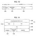
- PESis transmitted with a form further partitioned into smaller 188-byte packets called transport stream (TS) packets. As shown in Fig.
- the TS packetincludes a 4-byte header and a 184-byte payload for storing data.
- Fig. 14shows the structure of the header of the TS packet.
- the TS headeris composed of a 1-byte synchronization byte (Ox47) 133, a flag 134 representative of the attribute of the TS packet (the explanation of the contents of the flag will be omitted since they are not important to the present invention), 13-bit packet identifiers (hereinafter abbreviated to PID) 135 and 136, a scramble control identifier 137, an adaptation field identifier 138, and a 4-bit cyclic counter 139 used for checking the continuity of the packet.
- PIDpacket identifiers
- a field called adaptation fieldcan be transmitted prior to a data field which is called payload and is used for storing video data.
- a program clock reference(hereinafter abbreviated to PCR) aiming at the clock synchronization of the system and private data can be stored in the adaptation field. It is prescribed that when the adaptation field is transmitted using the TS packet, the existence of the adaptation field should be designated by an adaptation field identifier in the TS header.
- the MPEG systemis a system developed corresponding to CATV or digital satellite broadcasting
- a service utilizing an MPEG imageis recently provided by a network called the Internet having grown with the main object of data communication between computers.
- the Internet Engineering Task Force(hereinafter abbreviated to IETF) is pushing on standardization.
- RTP Payload Format for MPEG1/MPEG2 Video(hereinafter abbreviated to RFC 2038) has standardized a transmission method and a packet encapsulation system.
- RTPA Transport Protocol for Real-Time Applications
- RTPA Transport Protocol for Real-Time Applications
- UDPuser datagram protocol
- IP packetInternet Protocol packet
- WO 97/20413discloses a packet switching system in which packets consistent with a network protocol are packed into packets of a digital transport stream and part of the address of the receiver is used as a packet identifier in the digital transport stream.
- a system for performing video transmission on the basis of an MPEG-TS systemincludes a digital satellite broadcasting system and a digital CATV system, as mentioned above.
- the digital CATV system of those servicesis a service closely related with an area.
- the digital CATV systemis constructed with a relatively narrow area taken as a service providing area. Therefore, each CATV business proprietor possesses a CATV center (hereinafter referred to as head end) for delivering programs or contents and an access network for transmitting a video signal so that a ground/satellite broadcasting program received at the head end is retransmitted and/or programs or video contents stored in the head end are transmitted, as required.
- head endfor delivering programs or contents
- an access networkfor transmitting a video signal so that a ground/satellite broadcasting program received at the head end is retransmitted and/or programs or video contents stored in the head end are transmitted, as required.
- VODvideo-on-demand
- the serviceis structured in a form in which a digital compression signal of a program is held at a head end in a manner similar to that mentioned above.
- the video-on-demand servicehas a problem that a service maintenance cost including the purchase of a rebroadcasting right (or copyright) of video contents in order to hold the video contents, a digital compression processing for the video contents, the storage of compressed or coded video, and so forth is expensive and hence it is not commercially profitable unless the number of times of access to the same contents is made as large as possible.
- An effective method for solving this problemis such that a plurality of CATV business proprietors hold video contents in cooperation and the contents are utilized through the transmission thereof using a communication network when necessary.
- the structuring of such a systemhas a need to connect the head ends and networks of the plurality of CATV business proprietors by the communication network.
- a CATV head end in U.S.A. and a set top box (hereinafter abbreviated to STB) in Japanwhich is a video receiver equipment of a CATV subscriber
- STBset top box
- MPEG-TSbeing generally utilized in the digital CATV is transmitted as it is.
- the video transmission based on MPEG-TShas a problem that a dedicated communication network such as ATM network, satellite network or the like must be used and the charge for communication using this dedicated network is expensive.
- the dedicated networkpremises the utilization thereof with a contract point kept in a normally connected condition and hence a great problem is offered in the cost performance aspect in the case where there is used for a service in which the network is occupied in accordance with user's requests as in the demand-on-service.
- An object of the present inventionis to enable video transmission based on an MPEG-TS packet without using such a dedicated network.
- the Internetis a network ramified over the whole world and has a feature that a dynamic change in connection is possible by using an address applied to an individual client or host computer. Namely, there is no need to fix a connection point beforehand or the connection is effected by use of an address when video transmission is desired. Therefore, free connection setting and low-cost video communication incapable of being realized by the dedicated network are possible.
- the existing Internethas a problem that a transmission band width or the like is narrow, it can easily be foreseen that the insufficiency of band will be eliminated in the near future by ensuring a transmission band by a giga bit router, a resource reservation setup protocol (RSVP) or the like, whereby a global network environment can be realized by the Internet.
- RSVPresource reservation setup protocol
- a problem arising newly when the CATV networks are connected by use of the Internet, as mentioned above, that is, the problem of a need of the protocol conversion between an MPEG transport protocol used in the CATV network and an IP protocol used in the Internetcan be solved by providing an interworking unit for performing the conversion between the MPEG-TS protocol and the Internet protocol.
- Requirements for a high-speed and low-cost processing in the interworking unitcan be met by providing means for improving a packet forming method and a packet conversion method for packets to be transmitted in the MPEG network and the IP network.
- packet forming meanswith which the transmission is made with the header of an IP packet stored in a private data region of an adaptation field prescribed in the MPEG-TS system and the interworking unit makes no analysis of private data of the adaptation region or causes the private data to transmit in the Internet with the private data used as the header of the IP packet as it is, and (2) means with which when an MPEG video signal is transmitted from the Internet, the transmission is made with the provision of the condition that an IP packet to be transmitted is restricted in size so that it can be accommodated into a payload without the remainder when the IP packet is divided into MPEG-TS packets.
- the video stream in the MPEG-TS packetis distinguished by a PID value.
- the video streamis distinguished by an IP address. Accordingly, when the MPEG-TS packet is to be transferred by use of the IP packet, there is a need to make the conversion between the PID value and the IP address by use of any method.
- Another object of the present inventionis to solve a problem arising in the case where an IP packet of a video signal transmitted in an IP format is received and the received signal is transmitted in a TS-packetized form.
- This problemwill now be described taking a video transmission system as an example.
- video datais transmitted from a video server to a client in an IP format with the data stored in an IP packet.
- the transmission/receptionis possible irrespective of the inner data format of the IP packet if the transmitting side and the receiving side recognize the transmission format of data.
- DAVIC networkDigital Audio Visual Council
- STBSet Top Box
- a desired packetis received on the basis of a system in which a packet is broadcast to the network with an address or rather packet identifier (PID) applied to the packet and a client wanting that packet selectively receives that packet in dependence on the PID. Since the TS packet is thus distinguished by the PID value, the following problem arises when IP of an IP packet is terminated for TS packetization. Namely, if there is no correspondence for conversion between an IP address and a PID value, it becomes impossible for an STB on the receiving side to make the judgement of which PID does a TS packet to be received possess.
- PIDpacket identifier
- the object of the present inventionis to provide a method and equipment for conversion between an IP address and a PID value required in the case where IP-packetized video data is received and the received data is retransmitted in a TS-packetized form.
- the present inventionis characterized in that the value of lower 8 bits (Bit: 7-0) of an IP address and the value of lower 8 bits (Bit: 7-0) of a PID value are made the same, and upper 24 bits (Bit: 31-8) of the IP address are degenerated into 5 bits so that the degenerated 5 bits are made to correspond to upper 5 bits (Bit: 12-8) of the PID value.
- degeneratedor "degeneracy” used herein means the conversion of, for example, a 24-bit value into a 5-bit value. In the case where a channel, for example, as described, a frequency for transmission of the TS packet is different, it is possible to set the same degeneracy value (5 bits).
- the present inventionis characterized in that the value of lower 8 bits (Bit: 7-0) of an IP address and the value of lower 8 bits (Bit: 7-0) of a PID value are made the same, and upper 24 bits (Bit: 31-8) of the IP address are degenerated into a 5-bit value of 1 to 30 excepting 0 and 31 so that the degenerated 5 bits are made to correspond to upper 5 bits (Bit: 12-8) of the PID value.
- the present inventionis characterized in that the value of lower 8 bits (Bit: 7-0) of an IP address and the value of lower 8 bits (Bit: 7-0) of a PID value are made the same, upper 24 bits (Bit: 31-8) of the IP address are degenerated into 3 bits so that the degenerated 3 bits are made to correspond to bits 10 to 8 of the PID value, and bits 12 and 11 of the PID value are made to correspond to 1 and 0, respectively.
- the present inventionis characterized in that the value of lower 8 bits (Bit: 7-0) of an IP address and the value of lower 8 bits (Bit: 7-0) of a PID value are made the same, upper 24 bits (Bit: 31-8) of the IP address are degenerated into 2 bits so that the degenerated 2 bits are made to correspond to bits 9 to 8 of the PID value, and bits 12 to 10 of the PID value are made to correspond to the category of data transmitted by an IP packet.
- the present inventionis characterized in that the value of lower 8 bits (Bit: 7-0) of an IP address and the value of lower 8 bits (Bit: 7-0) of a PID value are made the same, upper 24 bits (Bit: 31-8) of the IP address are degenerated into 2 bits so that the degenerated 2 bits are made to correspond to bits 9 to 8 of the PID value, and the conversion into a 3-bit value of 1 to 6 excepting 0 and 7 is made for each category of data transmitted by an IP packet so that the converted 3-bit value is made to correspond to 3 bits including bits 12 to 10 of the PID value.
- the present inventionis characterized in that a device for receiving IP-packetized video data and retransmitting it after TS-packetization transmits data indicative of the correspondence for conversion between an IP address and a PID value in a form multiplexed with retransmission video data to a video data receiving device.
- the present inventionis characterized in that data indicative of the correspondence for conversion between an IP address and a PID value generated by the method according to any one of the first to fifth means is transmitted to a video data receiving device each time an IP packet having a different IP address is received and is TS-packetized.
- the present inventionis characterized in that a retransmitting device transmits data indicative of the correspondence for conversion between an IP address and a PID value generated by the method according to any one of the first to fifth means and data indicative of the correspondence between the IP address and a frequency number for multiplexing of TS packet to a video data receiving device each time an IP packet having a different IP address is received and is TS-packetized.
- the present inventionis characterized in that a device for receiving IP-packetized video data and retransmitting it after TS-packetization and a device for receiving the TS-packetized and retransmitted video data hold data indicative of the correspondence for conversion between an IP address and a PID value beforehand.
- the present inventionis characterized in that a device for receiving IP-packetized video data and retransmitting it after TS-packetization and a device for receiving the TS-packetized and retransmitted video data hold data indicative of the correspondence for conversion between an IP address and a PID value generated by the method according to any one of the first to fifth means beforehand.
- the present inventionis characterized in that a device for receiving IP-packetized video data and retransmitting it after TS-packetization and a device for receiving the TS-packetized and retransmitted video data hold data indicative of the correspondence for conversion between an IP address and a PID value generated by the method according to any one of the first to fifth means and data indicative of the correspondence between the IP address and a frequency number for multiplexing of TS packet beforehand.
- the present inventionis characterized by comprising means with which a device for receiving IP-packetized video data and retransmitting it after TS-packetization and a device for receiving the TS-packetized and retransmitted video data hold data indicative of the correspondence for conversion between an IP address and a PID value generated by the method according to any one of the first to fifth means and data indicative of the correspondence between the IP address and a frequency number for multiplexing of TS packet beforehand, and the retransmitting device can transmits the video data after the IP packet to TS packet conversion on the basis of the data indicative of the correspondence between the IP address and a frequency number for multiplexing of TS packet so that the video data is transmitted to that one of a plurality of connected post-stage transmitting devices which is designated by the data.
- Fig. 9shows an embodiment representing the connection configuration of a CATV system according to the present invention.
- This CATV systemis characterized in that CATV networks 61 and 56 at two locations are connected by the Internet 50.
- this CATV systemincludes a video server 60, the first CATV network 61 connected to the video server 60, the Internet 50, an interworking unit 62 for connecting the Internet 50 and the CATV network 61, the second CATV network 56, and an interworking unit 54 for connecting the CATV network 56 and the Internet 50.
- An STB (Set Top Box) 57 for receiving a video signalis connected to the CATV network 56.
- a video signal from the video server 60is transmitted to the Internet 50 through the interworking unit 62 and is sent to the interworking unit 54 by means of a router network 51.
- the interworking unit 54supplies the video signal transmitted using the Internet to the CATV network 56, thereby enabling video reception at the STB 57.
- a video signalis transmitted on the basis of an MPEG-TS system, as having already been described in the paragraph of BACKGROUND OF THE INVENTION.
- video transmission based on an Internet protocol represented by RFC 2038is performed.
- the interworking unit 62 for interconnecting such networks with different protocolshas a function of converting a video signal transmitted on the basis of the MPEG-TS protocol into a format conformable to the Internet protocol.
- the interworking unit 54has a function of converting a video signal transmitted on the basis of the Internet protocol into a format based on the MPEG-TS protocol.
- the gist of the present inventionlies in that a video signal supplied on the basis of the MPEG-TS protocol is transmitted through the Internet. Accordingly, the signal supply source is not limited to only the video server.
- MPEG signal supplying devices other than the video serverinclude a real-time MPEG encoder and a receiving equipment which receives satellite broadcasting to output an MPEG signal. It is needless to say that the gist of the present invention is satisfied by those devices, too.
- the gist of the present inventionlies in that a signal transmitted on the basis of the MPEG-TS system by use of an interworking unit is converted into a format capable of being transmitted by the Internet so that the converted signal is transmitted by the Internet and that a signal transmitted by use of the Internet is converted into an MPEG-TS signal again by an interworking unit so that the converted signal is transmitted to a CATV network.
- a common video transfer protocolin which the video transmission from a server on the Internet to a STB on a CATV network and the video transmission from a video server on a CATV network to a client's personal computer (PC) on the Internet are taken into consideration in addition to the CATV connection through the Internet described in conjunction with the first embodiment as well as a system with which protocol conversion between different networks is performed.
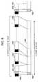
- Fig. 8shows a connection diagram in a network construction which enables both the video transmission from a video server 55 on a CATV network 56 to a client 4 on the Internet 50 and the video transmission from a server 52 on the Internet 50 to an STB 57 on the CATV network 56.
- the video server 55transmits a video signal with a packet construction shown in Fig. 1 .
- This video signalreaches an interworking unit 62 on the basis of an MPEG-TS system through the CATV network 56.
- the interworking unit 62receives the video signal sent thereto on the basis of the MPEG-TS system to protocol-convert it through a predetermined conversion system (which will be mentioned later on) into packets transmissible on the basis of the Internet protocol and transmits the converted signal to the Internet 50.
- the Internet 50sends the video signal to the client 4 by use of the Internet protocol.
- This signalcan be transmitted to an interworking unit 54 by a manner similar to that at the time of transmission to the client 4.
- protocol conversion to MPEG-TSis made again by the interworking unit 54.
- Fig. 1corresponds to an embodiment showing the construction of an MPEG-TS signal to be transmitted from the video server 55 (see Fig. 8 ) to the Internet 50, the STB 57 connected to the CATV network 56 and an STB on another CATV network connected through the interworking unit 54.
- MPEG-TSthere are permitted the case where a payload having data stored therein is transmitted subsequently to a 4-byte TS header 1 and the case where an adaptation field 2 is transmitted prior to the payload.
- a TS including the transmission of an IP headeris such that the adaptation field 2 is inserted always immediately after the TS header and the IP header is transmitted using this adaptation field 2, as shown in Fig. 1 .
- the adaptation field 2is stored with a 2-byte flag 4 indicative of the contents of data to be transmitted and private data 5.
- the transmission of the private data 5is indicated by a transport private data flag or a flag indicative of the contents of the adaptation field and the size of the private data 5 is set as a transport private data length in the flag.
- a 20-byte IP packet header 6is stored as the private data 5 in a bit arrangement as it is.
- the IP packet headeris composed of a 4-bit field indicative of a version, a header length, a service type, a total packet length, identifiers, a source IP address and a destination IP address.
- the IP packet headeris formed with 20 bytes. Since no option is used under a general condition, the transmission is made with data inclusive of a 20-byte field stored in the private data region as it is.
- the payload of the TS subsequent to the adaptation fieldis stored with data in a PES (Packet Elementary Stream) format.
- PESPacket Elementary Stream
- Fig. 1shows an example of transmission with only the IP packet header included as the private data
- a UDPUser Datagram Protocol
- RTPReal Time Protocol
- Fig. 2corresponds to an embodiment in the case where a UDP header 10 is stored subsequently to an IP header 6 as private data
- Fig. 3corresponds to an embodiment in the case where the transmission is made with an IP header 6, an UDP header 10 and an RTP header 14 included as private data 13.
- the present inventionis characterized in that data of a packet header of a protocol used in an IP network is transmitted as private data.
- the present inventionis not limited to a specified protocol such as UDP or RTP.
- a specified protocolsuch as UDP or RTP.
- the packet construction shown in Fig. 3is the best.
- the embodiments shown in Figs. 1, 2 and 3have been described in conjunction with the case where the IP header, the UDP header or the RTP header is transmitted as the private data, as it is.
- data necessary for constructing an IP headercan be transmitted as private data with a changed form.
- the video server 55also transmits the video signal to the STB 57 connected to the CATV network.
- video to be transmitted to the internet 50 and video to be transmitted to the STB 57are used in common.
- the use of the PES system employed in the conventional CATVis most suitable. Since information of the IP header encapsulated into the adaptation field is processed separately from video and audio signals, no influence is given on video reproduction by the conventional STB 57.
- the use of the PES formatmakes it possible to transmit the video signal to the IP network while maintaining the signal compatibility with the conventional STB.
- PESis constructed by dividing ES into a plurality of packets and thereafter applying a PES header to each packet. Therefore, PES can easily be converted into ES. Accordingly, a client capable of receiving and decoding ES can perform the decoding with little addition of a function.
- the maximum transfer unit (MTU) size of an IP packetis 1500 bytes when Ethernet is used. Accordingly, the number of 184-byte payloads of MPEG-TS capable of being packed is seven at the greatest. Thus, in transmitting TS packets, they are transmitted with an IP header included at the period of 7TS. As conceptually shown in Fig. 6 , the interworking unit receiving packets including IP headers forms an IP header and thereafter connects data of payloads in subsequently transmitted TS packets to the IP header, thereby forming an IP packet.
- the MTU size in the Internetis 1500 bytes but there may be the case where the MTU size in the other physical network is different than that.
- the IP header transmission periodcan be changed in accordance with the MTU size.
- a condition in the present inventionis that the total bytes of TS packet payloads in an interval from a TS packet inclusive of an IP header to a TS packet inclusive of the next IP header does not exceed the number of bytes defined by the MTU.
- FIG. 12illustrates an embodiment showing the flow of processings in the interworking unit. It is assumed that the video server on the CATV network transmits an MPEG-TS signal (see Figs. 13 and 14 ) in accordance with an encapsulation system as shown in Fig. 2 . As shown by a procedure of Fig. 12 , the interworking unit receives the transmitted MPEG-TS signal (or packet) (step 100) to extract therefrom a signal to be transmitted to the IP network.
- the selection of the MPEG-TS packet to be transmittedis made by checking a PID 135 in a TS packet header (steps 102 and 103). In the case where the packet is not one to be transmitted to the IP network, that packet is rejected (step 111). In the case where the packet is one to be transmitted to the IP network, a flag 138 indicative of the presence/absence of an adaptation field in a TS header of that packet is checked (steps 104 and 105). In the case where the check of the flag 138 results in that there is an adaptation field, the TS header of that packet is deleted (step 106) and flag information of the adaptation field is thereafter deleted (step 107). As a result, a private data portion of the adaptation field and the subsequent payload portion are outputted (step 108).
- the interworking unitdeletes the TS header and transmits an IP packet header stored as the private data and subsequently image data as the payload.
- the interworking unit 54 shown in Fig. 8 or 9is inputted with an IP packet including an IP header, an UDP header, an RTP header and PES data. Private data as the collection of a 2-byte adaptation related flag and IP related headers (IP, UDP and RTP headers) is stored as an adaptation field into TS. The remaining or payload of this TS is filled with PES data, thereby ultimately forming a 188-byte TS packet. The remaining payload of the IP packet is partitioned every 184 bytes so that each part is accommodated into a TS payload. There is no possibility that the IP header is used in the CATV network.
- Fig. 4is a diagram showing a third embodiment of the present invention.
- the construction of a network to which the present embodiment is appliedis the network construction shown in Fig. 8 or 9 .
- the embodiment shown in Fig. 4is different from the embodiment of Fig. 1, 2 or 3 in that the transmission is made with a program clock reference (PCR) too included in an adaptation field and that an RTP header is included in an IP packet to be transmitted as private data.
- PCRprogram clock reference
- a field for recording time information or time stampis provided in a RTP packet header in order to ensure the transmission of data such as a video signal necessitating the real time transmission.
- PCRis utilized for reproducing system clocks of a TS decoding circuit.
- the time stamp of RTPis caused from the digitization of a time at a fundamental frequency of 90 kHz in the same manner as PCR. Therefore, it is possible to use PCR as the time stamp of RTP.
- the embodiment shown in Fig. 4is characterized in that PCR transmitted by means of a PCR field 22 of the adaptation field is used in a time stamp field 26 of RTP, as shown in Fig. 5 .
- the time stamp of RTP and a base portion of RTPrepresent time information by the bit widths of 32 bits and 33 bits, respectively. Therefore, it is possible to attain the bit width matching by using lower 32 bits of PCR.
- time information transmitted as PCRis thus utilized as the time stamp of RTP lies in that the inclusion of ultimately corrected accurate time information into the RTP header is possible even in the case where PCR is relocated for the purpose of correcting packet transmission jitter generated in a CATV network.
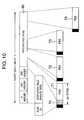
- Fig. 10shows an embodiment illustrating the encapsulation of data when video transmission is made toward the CATV network 56 (see Fig. 8 ) from the server 52 connected to the IP network.
- the interworking unit 62needs an operation of converting an MPEG video signal (PES) transmitted by use of an IP packet into an MPEG-TS signal.
- PESMPEG video signal
- This converting operationwill be described referring to Fig. 10 .
- video datais encapsulated on the basis of a PES format in order to facilitate the conversion into TS. Accordingly, this IP packet is constructed with an IP header and a payload in a PES format.
- the IP packetis transmitted from the server on the IP network with the IP packet constructed to have a packet size such that the addition of 2 to the packet size (or the size of data including an IP header and a payload) is integer times as large as 184.
- a leading portion including the IP packet headeris extracted by 182 bytes and is added with a 2-byte flag of an adaptation field so that the resultant is stored as a 184-byte payload of MPEG-TS.
- an MPEG-TS headeris applied to this payload, thereby forming an MPEG-TS packet.
- the succeeding IP packetis partitioned every 184 bytes and the TS packet header is applied to each part for the conversion into MPEG-TS.
- the feature of the present embodimentlies in that by imposing a restriction on the size of an IP packet transmitted from a server on an IP network which transmits an MPEG image, the division and reconstruction of the packet in an interworking unit are very simplified.
- the total length of an IP packetmay be integer times as large as 184 bytes plus 176 bytes.
- a fifth embodiment of the present inventioncorresponds to a modification of the second embodiment.
- the IP headeris directly mapped as the private data of MPEG-TS.
- a region 150 indicating the attribute of private datais provided in a leading byte of the private data, as shown in Fig. 15 .
- the interworking unituses this flag to make the judgement as being an IP packet or not or the judgement of utilization/rejection. Since the data in the attribute region is unnecessary in the IP network, there is a need to reject it in performing protocol conversion by the interworking unit.
- Fig. 15shows an example in which the 1-byte attribute region is provided, it does not necessarily follow that the size of the attribute region is one byte. it can easily be understood that the size of the attribute region may be a plurality of bytes.
- IP/PID conversion equipmentan equipment therefor (hereinafter referred to as IP/PID conversion equipment) according to the present invention will be described in detail.
- the descriptionis made using a DAVIC network as a network which uses MPEG-TS packets.
- the CATV system portion shown in conjunction with the first to fifth embodimentscorresponds to the DAVIC network in the following embodiments.
- Fig. 26shows a diagram of the network construction.
- Reference numeral 400denotes the Internet network
- numeral 200denotes a DAVIC network.
- a client or personal computer (PC) 402can make a request for video transmission to a video server 401, thereby receiving desired video data in an IP packet format and reproducing it.
- PCpersonal computer
- STBSet Top Box
- reference numeral 310denotes an interworking unit for interconnecting the Internet and the DAVIC network, numeral 301 a router, numeral 302 an IP/PID equipment according to the present invention, numeral 303 a DAC (Dial-up Access Concentrator), numeral 304 a QAM (Quadrature Amplitude Modulation), numeral 201 an access network, numeral 305 the STB, and numeral 306 a TV.
- DACDial-up Access Concentrator
- QAMQuadrature Amplitude Modulation
- the DAC 303concentrates accesses from a plurality of users and establishes a line for the video server on the Internet through the router 301 in the interworking unit 310. Thereafter, the user refers to a video guide or electronic program guide (EPG) displayed on the TV 306 to select a desired program.
- EPGelectronic program guide
- the video server 401 on the Internetencapsulates the requested video data into IP packets and transmits the IP-packetized data to the requesting STB.
- the video data in the IP packet format transmitted from the video server 401is transferred through the router 301 to the IP/PID conversion equipment 302 according to the present invention.
- the IP/PID conversion equipment 302generates PID from the IP address of the received IP packet to convert the received video data in the IP packet format into video data in a TS packet format applied with the generated PID and transmits the TS-packetized video data to the QAM 304.
- the QAM 304subjects the received video data in the TS packet format to QAM modulation and transmits the modulated data to the access network 210.
- the STB 305receives the desired video data by selecting, from the signal received from the access network 210, a frequency at which the desired data is modulated and a TS packet with which the desired data is transmitted. Also, the STB 305 decodes the received video data and transmits the video image to the TV 306 which in turn reproduces and displays the video image.
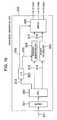
- Fig. 16is a block diagram showing the construction of the IP/PID conversion equipment according to the sixth embodiment
- Fig. 17is a diagram showing the correspondence for conversion between an IP address and a PID value
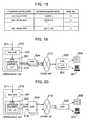
- Fig. 18shows the contents of data in an LUT (Look-Up Table) shown in Fig. 16 .
- LUTLook-Up Table
- lower 8 bits (Bit: 7-0) of an IP address and lower 8 bits (Bit: 7-0) of a PID valueare made the same and upper 24 bits (Bit: 31-8) of the IP address are degenerated into 5 bits so that the degenerated 5 bits are converted into upper 5 bits (Bit: 12-8) of the PID value.
- the IP/PID conversion equipment shown in Fig. 16includes a buffer 321 for receiving an IP packet, a CPU 322, an LUT 323 for holding data indicative of the conversion between an IP address and a PID value (or an IP address to PID value conversion table), a TS header generating unit 324 for generating a TS header, an IP data holding unit 325 for holding data of the IP packet, and a switch 326 for transmitting video data in a TS packet format to a predetermined QAM.
- the IP/PID conversion equipment shown in Fig. 16first receives video data 311 in a IP packet format by the buffer 321.
- the CPU 322reads the IP packet from the buffer 321 to transmit data 312 of lower 8 bits (Bit: 7-0) of an IP address to the TS header generating unit 324 and data 313 of upper 24 bits (Bit: 31-8) thereof to the LUT 323.
- the CPU 322also transmits IP packet data 314 to the IP data holding unit 325.
- the TS header generating unit 324generates the PID value of a TS packet on the basis of the data 312 of lower 8 bits (Bit: 7-0) of the IP address from the CPU 322 and the data 315 from the LUT 323 resulting from the degeneracy of the data 313 of upper 24 bits (Bit: 31-8) of the IP address from the CPU 322 into 5 bits and generates a header of the TS packet.
- the switch 326reads TS header data 317 from the TS header generating unit 324 and IP data 318 from the IP data holding unit 325 which turns into data of the TS packet.
- the TS header data 317 and the IP data 318 as the TS packet dataare transmitted to a predetermined QAM number for multiplexing QAM (any one of QAM1 to QAM3) in accordance with the QAM number for multiplexing QAM data 316 from the LUT 323.
- Fig. 17is a diagram showing the correspondence between the IP address of a received IP packet and the PID value of a TS packet to be transmitted.
- the value 331 of lower 8 bits (Bit: 7-0) of the IP addressis converted into the value 332 of lower 8 bits (Bit: 7-0) of the PID value.
- the value 333 of upper 24 bits (Bit: 31-8) of the IP addressis degenerated into a 5-bit value as a network number value for conversion into the value 334 of upper 5 bits (Bit: 12-8) of the PID value.
- the term of "degenerated” or “degeneracy” used hereinmeans the conversion of a 24-bit value into a 5-bit value. This degeneracy or conversion will specifically be described using Fig. 18 .
- Fig. 18is a diagram showing that correspondence between the upper 24-bit (Bit: 31-8) value 333 of an IP address, a 5-bit value as a network number value, and a QAM number for output value which is held in the LUT 323 shown in Fig. 16 .
- the IP address of 128.155.30.XXX series(XXX indicating any value of 0 to 255) is converted into a network number 1 (00001 in a binary number).
- the IP address of 128.155.40.XXX seriesis converted into a network number 2 (00010) and the IP address of 128.155.80.XXX series is converted into a network number 30 (11110).
- the PID valuemay overlap the prescribed value in accordance with the lower 8-bit value.
- the PID valuecomes to 1 (hexadecimal number: 0x0001) which overlaps the value prescribed by H.222.0 for use.
- This problem or such overlappingcan be avoided by establishing a prohibition rule for avoiding the case where there overlaps the value prescribed by H.222.0 or by using 1 to 30 as the network number.
- the descriptionhas been made in conjunction with the conversion of the upper 24-bit (Bit: 31-8) value 333 of the IP address into the 5-bit value.
- Fig. 18further shows the correspondence between the upper 24-bit (Bit: 31-8) value 333 of an IP address and a QAM number for TS packet output.
- This correspondencerepresents a relationship between the IP address upper 24-bit (Bit: 31-8) value 333 inputted to the LUT 323 shown in Fig. 16 and the data 316 outputted therefrom as the value of a QAM number for output of transmission data (or TS packet).
- the example shown in Fig. 18indicates that in the case where users of 128.150.30.XXX and 128.150.40.XXX series make access to the server on the Internet, requested data is transmitted to the users through the QAM (or frequency) of a QAM number (QAM No.) 1.
- requested datais transmitted to the users through the QAM (or frequency) of a QAM number 3.
- a QMA number for transmissionis designated for the IP address series of a data requesting user
- the number of users holding in common the amount of data capable of being transmitted by one QAMcan be set for each IP address series.
- 30 ones of series designated by upper 24 bits (Bit: 31-8) of each IP addresscan be used.
- a PID value13 bits is formed from an IP address (32 bits) and this conversion is performed in the LUT 323 and the TS header generating unit 324 which are shown in Fig. 16 .
- a QAM (or frequency) number for transmission of datais designated in the LUT 323 from the series of the IP address.
- requested dataor IP packet is converted by the interworking unit into a TS packet and is then QAM-transmitted.
- the receiving sidedoes not know the PID value of TS and a QAM number with which desired data is transmitted, the receiving side cannot make the selective reception of data. A method for receiving desired data will now be described using Figs. 19 and 20 .
- Fig. 19is a diagram showing the case where each of a data transmitting interworking unit 310 and a data receiving STB 305 holds data indicative of the correspondence for conversion between an IP address and a PID value (or an IP address to PID value conversion table).
- reference numerals used in Fig. 19are the same those used in Figs. 16 and 26 .
- An LUT 323 in Fig. 19is the same as the LUT 323 in Fig. 16 , that is, a look-up table having data indicative of the correspondence for conversion between an IP address and a PID value and a frequency (or QAM number) for transmission of data.
- Fig. 19is a diagram showing the case where each of a data transmitting interworking unit 310 and a data receiving STB 305 holds data indicative of the correspondence for conversion between an IP address and a PID value (or an IP address to PID value conversion table).
- reference numerals used in Fig. 19are the same those used in Figs. 16 and 26 .
- the transmitting interworking unit 310converts an IP packet received through a router 301 into a TS packet in accordance with the LUT 323 possessed by the interworking unit 310 and transmits the TS packet to the QAM 304.
- the QAM 304modulates the TS packet and transmits the modulated TS packet to an access network 210.
- the STB 305refers to the LUT 323 on the basis of its own IP address to select, from the received signals having a plurality of frequencies, a signal having a frequency at which desired data is transmitted and to select a TS packet having a PID value designated by the LUT 323, thereby receiving the desired data.
- the received datamay be decoded so that it is reproduced by the TV 306.
- the received datamay be further transmitted to a personal computer (PC) 307 or the like connected to the STB 305
- PCpersonal computer
- each of the STB 305 and the PC 307holds an LUT similar to the above-mentioned LUT 323. Thereby, it is possible to further transmit the received TS packet to the PC 307.
- Fig. 20shows a modified example of the case shown in Fig. 19 .
- data indicative of the correspondence for conversion between an IP address and a PID value and data indicative of the correspondence between the IP address and a frequency (or QAM number) for transmission of dataare transmitted from the interworking unit 310 to the STB 305.
- the correspondence for conversion between an IP address and a PID value and the correspondence between the IP address and a frequency (or QAM number) for transmission of dataare held by both the interworking unit 310 and the STB 305.
- Fig. 19the correspondence for conversion between an IP address and a PID value and the correspondence between the IP address and a frequency (or QAM number) for transmission of data are held by both the interworking unit 310 and the STB 305.
- the interworking unit 310when the interworking unit 310 receives an IP packet 311 having a novel IP address and performs the conversion thereof into a TS packet and the transmission of the TS packet to the QAM, the interworking unit 310 transmits data 319 indicative of the correspondence for conversion between the novel IP address and a PID value and a TS packet transmission frequency (or QAM number) to the STB 305 through the QAM 304.
- a specified frequency (or QAM number) and a specified PID value with which the correspondence data between the IP address and the PID value and the TS packet transmission frequency (or QAM number) are transmittedshould be set beforehand.
- the STB 305receives a TS packet having the specified frequency (or QAM number) and PID value, there exists data indicative of the correspondence for conversion between the IP address and the PID value and the frequency (or QAM number) for transmission of TS packet and hence it is necessary to hold the data by use of a memory or the like in the STB 305.
- the STB 305selects, on the basis of the transmitted data transmission frequency (or QAM number), a signal having a frequency at which desired data is transmitted and selects a TS packet having a PID value designated by the received correspondence for IP address to PID value conversion, thereby receiving the desired data.
- the interworking unit 310each time the interworking unit 310 receives an IP packet having a novel IP address and performs the conversion thereof into a TS packet and the transmission of the TS packet, the interworking unit 310 transmits a frequency for transmission of TS packet and a PID value to the STB 305. Thereby, the STB 305 can receive a desired TS packet.
- the PID value of a TS packetis formed from the IP address of an IP packet, the series of the IP address is defined from upper 24 bits of the IP address and a frequency for transmission of data is set for each IP address series.
- the conversion between the IP address and the PID valueis possible. Also, there can be obtained an effect that the number of users (or the number of IP addresses) subjected to multiplex transmission at one frequency can be set for each IP address series unit.
- Figs. 21 and 22are diagrams showing the correspondence between the IP address of an IP packet and the PID value of a TS packet in a seventh embodiment of the present invention.
- Fig. 21corresponds to the modification of the example shown in Fig. 17 .
- the value 331 of lower 8 bits (Bit: 7-0) of an IP addressis converted into the value 332 of lower 8 bits (Bit: 7-0) of a PID value.
- the value 333 of upper 24 bits (Bit: 31-8) of the IP addressis degenerated into a 3-bit value as a network number value for conversion into the 3-bit (Bit: 10-8) value 335 of bits 10 to 8 of the PID value. This will be mentioned later on in conjunction with Fig. 22 .
- bits 12 and 11 of the PID value denoted by reference numeral 336are fixed to 1 and 0, respectively.
- Fig. 22corresponds to the modification of the example shown in Fig. 18 and is a diagram showing that correspondence between the value 333 of upper 24 bits (Bit: 31-8) of the IP address, the 3-bit value 335 as a network number value and the value of a QAM number for output which is held in the LUT 323 shown in Fig. 16 .
- the value 333 of upper 24 bits (Bit: 31-8) of the IP addressis degenerated into 5 bits.
- Fig. 22however, it is degenerated into 3 bits.
- Fig. 22it is indicated that, for example, the IP address of 128.155.30.XXX series is converted into a network number 0 (000 in a binary number).
- Fig. 18in the case where the value of upper 16 bits (Bit: 31-16) of the IP address is of the same series, it is also possible to omit the upper 16 bits (Bit: 31-16) with the conversion table formed by use of only the remaining 8 bits (Bit: 15-8).
- Fig. 22further shows the correspondence between the value 333 of upper 24 bits (Bit: 31-8) of the IP address and a QAM number for TS packet output. The way of utilizing this correspondence is the same as that described in conjunction with Fig. 18 .
- 13 bits of a PID valueare constructed such that bits 12 and 11 are respectively fixed to 1 and 0, bits 10 to 8 use 3 bits into which the value 333 of upper 24 bits (Bit 31-8) of an IP address is degenerated, and the value of bits 7 to 0 is set to be the same as the value 331 of lower 8 bits (Bit: 7-0) of the IP address.
- Figs. 23 , 24 and 25are diagrams showing the correspondence between the IP address of an IP packet and the PID value of a TS packet in an eighth embodiment of the present invention.
- Fig. 23corresponds to the modification of the example shown in Fig. 17 .
- the value 331 of lower 8 bits (Bit: 7-0) of an IP addressis converted into the value 332 of lower 8 bits (Bit: 7-0) of a PID value.
- the value 333 of upper 24 bits (Bit: 31-8) of the IP addressis degenerated into a 2-bit value as a network number value for conversion into the 2-bit (Bit: 9-8) value 337 of bits 9 to 8 of the PID value.
- a 3-bit value corresponding to the category of datais inserted as the 3-bit (Bit: 12-10) value 338 of bits 12 to 10 of the PID value. This will be mentioned later on in conjunction with Fig. 25 .
- Fig. 24corresponds to the modification of the example shown in Fig. 18 and is a diagram showing that correspondence between the value 333 of upper 24 bits (Bit: 31-8) of the IP address, the 2-bit value 337 as a network number value and the value of a QAM number for output which is held in the LUT 323 shown in Fig. 16 .
- the value 333 of upper 24 bits (Bit: 31-8) of the IP addressis degenerated into 5 bits.
- Fig. 24it is degenerated into 2 bits.
- Fig. 24it is indicated that, for example, the IP address of 128.155.30.XXX series is converted into a network number 0 (00 in a binary number).
- Fig. 24further shows the correspondence between the upper 24-bit (Bit: 31-8) value 333 of the IP address and a QAM number for TS packet output. The way of utilizing this correspondence is the same as that described in conjunction with Fig. 18 .
- Fig. 25is a diagram showing the correspondence between the category of data and a 3-bit value as the category number value 338 shown in Fig. 23 .
- Fig. 25it is indicated that for example, the case where the category of data transmitted by a received IP packet is video corresponds to 2 (binary number: 010) and the case where it is audio corresponds to 1 (binary number: 001).
- the correspondence between the category of data and the category number value (3 bits) shown in Fig. 25is used, for example, in the case where PID values are set to different values in accordance with the category of data transmitted by the IP packet, as mentioned above.
- the overlapping of the PID value and the value prescribed by H.222.0 for usemay be generated in accordance with the network number value (2 bits) and the value of lower 8 bits, as in the case described in conjunction with Fig. 18 .
- a countermeasuresuch as the provision of a prohibition rule for avoiding the case where there overlaps the value prescribed by H.222.0 or the use of 1 to 6 as the category number value.
- 13 bits of a PID valueare constructed such that bits 12 to 10 are set to the category number value (3 bits), bits 9 to 8 use 2 bits into which the value 333 of upper 24 bits (Bit 31-8) of an IP address is degenerated, and the value of bits 7 to 0 is set to be the same as the value 331 of lower 8 bits (Bit: 7-0) of the IP address.
- This constructioncan provide an effect that it is possible to make the IP address to PID value conversion in which the PID value can be set to a different value in accordance with the category of data transmitted by the IP packet.
- the PID value of a TS packetis formed from the IP address of an IP packet, the series of the IP address is defined from upper 24 bits of the IP address and a frequency for transmission of data is set for each IP address series.
Landscapes
- Engineering & Computer Science (AREA)
- Multimedia (AREA)
- Signal Processing (AREA)
- Computer Networks & Wireless Communication (AREA)
- Computer Security & Cryptography (AREA)
- Data Exchanges In Wide-Area Networks (AREA)
- Compression Or Coding Systems Of Tv Signals (AREA)
- Two-Way Televisions, Distribution Of Moving Picture Or The Like (AREA)
- Communication Control (AREA)
Description
- The present invention relates to a method and system for transmitting an MPEG (Moving Picture Experts Group) image by use of the Internet Protocol (hereinafter referred to as IP). More particularly, the present invention relates to a network connection method using a transmission system conversion equipment for performing a rapid processing for conversion between an MPEG transport protocol and the Internet Protocol and a method for encapsulation of MPEG data to be transmitted. Also, the present invention relates to a method/equipment in which the conversion between an IP address and the PID (Packet Identifier) value of a TS (Transport Stream) packet is performed when a video signal transmitted using the Internet Protocol (IP) is to be transmitted by use of the H.222.0 system and a video transmission system which uses such a method/equipment.
- As an international standard for a system for transmitting a video signal in a digitally coded form, "GENERIC CODING OF MOVING PICTURES AND ASSOCIATED AUDIO: SYSTEMS" has been prescribed as ISO(International Organization for Standard)/IEC(International Electrotechnical Commission) 13818-1, ITU-T (International Telecommunication Union-Telecommunication Standardization Sector) H.222.0 Recommendation. This international standard for MPEG system (hereinafter referred to as H.222.0) has prescribed a standard for transmitting a video signal compressed on the basis of an MPEG system. Therein, two kinds of formats have been prescribed. One is a program stream (hereinafter abbreviated to PS) format supposing the transmission from a storage medium or the like for which the generation of bit error is relatively less. The other is a transport stream (hereinafter abbreviated to TS) format supposing a communication network for which the generation of transmission bit error is forecast.
- Since the present invention is directed to a code conversion system when a compressed or coded video signal is to be transmitted in a TS format, brief description will now be made of the prior art of a video transmission system based on the TS format. In an MPEG system the object of which is the coding and transmission of video and audio signals, an inputted video signal such as a television signal is digitized and the obtained digital signal is subjected to data compression by use of techniques including discrete cosine conversion, variable-length coding, and so forth. Though techniques used in conjunction with an audio signal are different from those in the case of the video signal, the audio signal is compressed by removing redundant data after digitization. The compressed signal is termed an elementary stream (hereinafter abbreviated to ES) and is data which forms an elementary part of the video/audio signal in conformity with the term. In the MPEG, this video/audio data is represented using the term of (bit) stream.
- In a cable television or community antenna television (CATV), satellite communication network, asynchronous transfer mode transmission network (hereinafter abbreviated to ATM network) or the like in which an MPEG video signal is transmitted, it is supposed that the generation of bit error at the time of data transmission is relatively frequent. Therefore, an elementary stream (ES) is transmitted in a form partitioned into small packets in order to narrow a range over which a trouble caused by transmission error extends. The packetized elementary stream (hereinafter abbreviated to PES) has a format in which header information called PES header is added to ES. In the transmission in the communication network exemplified above, PES is transmitted with a form further partitioned into smaller 188-byte packets called transport stream (TS) packets. As shown in
Fig. 13 , the TS packet includes a 4-byte header and a 184-byte payload for storing data.Fig. 14 shows the structure of the header of the TS packet. The TS header is composed of a 1-byte synchronization byte (Ox47) 133, aflag 134 representative of the attribute of the TS packet (the explanation of the contents of the flag will be omitted since they are not important to the present invention), 13-bit packet identifiers (hereinafter abbreviated to PID) 135 and 136, ascramble control identifier 137, anadaptation field identifier 138, and a 4-bitcyclic counter 139 used for checking the continuity of the packet. In the transport stream, a field called adaptation field can be transmitted prior to a data field which is called payload and is used for storing video data. A program clock reference (hereinafter abbreviated to PCR) aiming at the clock synchronization of the system and private data can be stored in the adaptation field. It is prescribed that when the adaptation field is transmitted using the TS packet, the existence of the adaptation field should be designated by an adaptation field identifier in the TS header. - Though the MPEG system is a system developed corresponding to CATV or digital satellite broadcasting, a service utilizing an MPEG image is recently provided by a network called the Internet having grown with the main object of data communication between computers. In order to ensure the interconnectability of communication in the Internet, the Internet Engineering Task Force (hereinafter abbreviated to IETF) is pushing on standardization. For the standard of an MPEG video transmission format, Request for Comment No. 2038: "RTP Payload Format for MPEG1/MPEG2 Video" (hereinafter abbreviated to RFC 2038) has standardized a transmission method and a packet encapsulation system. It is prescribed by RFC 2038 that the transmission should be made with ES, TS or PS of MPEG utilized as the format of a packet to be transmitted and that in order to prevent the degradation of resolution from being caused by transmission delay, the transmission should be made in accordance with "RTP: A Transport Protocol for Real-Time Applications" (hereinafter abbreviated to RTP) specified by RFC 1889. It is prescribed that an RTP packet should be stored in a packet based on a user datagram protocol (hereinafter abbreviated to UDP) and this UDP packet should be transmitted by use of the Internet Protocol packet (hereinafter abbreviated to IP packet). With the prior art described above, it is possible to transmit MPEG video data in such a manner that MPEG-TS packets are used in the CATV network while IP packets are used in the Internet.
WO 97/20413 - A system for performing video transmission on the basis of an MPEG-TS system includes a digital satellite broadcasting system and a digital CATV system, as mentioned above. The digital CATV system of those services is a service closely related with an area. Generally, the digital CATV system is constructed with a relatively narrow area taken as a service providing area. Therefore, each CATV business proprietor possesses a CATV center (hereinafter referred to as head end) for delivering programs or contents and an access network for transmitting a video signal so that a ground/satellite broadcasting program received at the head end is retransmitted and/or programs or video contents stored in the head end are transmitted, as required. In such a conventional CATV service, it is required that programs other than broadcast programs should be stored in, for example, VTR or the like and reproduced in accordance with delivering schedule. In a video-on-demand (VOD) service or the like expected as a near-future CATV service, too, it is general that the service is structured in a form in which a digital compression signal of a program is held at a head end in a manner similar to that mentioned above. The video-on-demand service has a problem that a service maintenance cost including the purchase of a rebroadcasting right (or copyright) of video contents in order to hold the video contents, a digital compression processing for the video contents, the storage of compressed or coded video, and so forth is expensive and hence it is not commercially profitable unless the number of times of access to the same contents is made as large as possible. An effective method for solving this problem is such that a plurality of CATV business proprietors hold video contents in cooperation and the contents are utilized through the transmission thereof using a communication network when necessary.
- The structuring of such a system has a need to connect the head ends and networks of the plurality of CATV business proprietors by the communication network. In order to connect, for example, a CATV head end in U.S.A. and a set top box (hereinafter abbreviated to STB) in Japan which is a video receiver equipment of a CATV subscriber, it is required that the connection should be made utilizing at least a communication network between U.S.A. and Japan. Under present conditions, however, it is not practical that MPEG-TS being generally utilized in the digital CATV is transmitted as it is. Namely, the video transmission based on MPEG-TS has a problem that a dedicated communication network such as ATM network, satellite network or the like must be used and the charge for communication using this dedicated network is expensive. Also, the dedicated network premises the utilization thereof with a contract point kept in a normally connected condition and hence a great problem is offered in the cost performance aspect in the case where there is used for a service in which the network is occupied in accordance with user's requests as in the demand-on-service.
- An object of the present invention is to enable video transmission based on an MPEG-TS packet without using such a dedicated network.
- To solve the above problems, means for connecting a plurality of CATV networks by the Internet is used in the present invention. The Internet is a network ramified over the whole world and has a feature that a dynamic change in connection is possible by using an address applied to an individual client or host computer. Namely, there is no need to fix a connection point beforehand or the connection is effected by use of an address when video transmission is desired. Therefore, free connection setting and low-cost video communication incapable of being realized by the dedicated network are possible. Though the existing Internet has a problem that a transmission band width or the like is narrow, it can easily be foreseen that the insufficiency of band will be eliminated in the near future by ensuring a transmission band by a giga bit router, a resource reservation setup protocol (RSVP) or the like, whereby a global network environment can be realized by the Internet.
- A problem arising newly when the CATV networks are connected by use of the Internet, as mentioned above, that is, the problem of a need of the protocol conversion between an MPEG transport protocol used in the CATV network and an IP protocol used in the Internet can be solved by providing an interworking unit for performing the conversion between the MPEG-TS protocol and the Internet protocol. Requirements for a high-speed and low-cost processing in the interworking unit can be met by providing means for improving a packet forming method and a packet conversion method for packets to be transmitted in the MPEG network and the IP network.
- More particularly, there are used (1) packet forming means with which the transmission is made with the header of an IP packet stored in a private data region of an adaptation field prescribed in the MPEG-TS system and the interworking unit makes no analysis of private data of the adaptation region or causes the private data to transmit in the Internet with the private data used as the header of the IP packet as it is, and (2) means with which when an MPEG video signal is transmitted from the Internet, the transmission is made with the provision of the condition that an IP packet to be transmitted is restricted in size so that it can be accommodated into a payload without the remainder when the IP packet is divided into MPEG-TS packets.
- In this case, the video stream in the MPEG-TS packet is distinguished by a PID value. In the IP packet, on the other hand, the video stream is distinguished by an IP address. Accordingly, when the MPEG-TS packet is to be transferred by use of the IP packet, there is a need to make the conversion between the PID value and the IP address by use of any method.
- Another object of the present invention is to solve a problem arising in the case where an IP packet of a video signal transmitted in an IP format is received and the received signal is transmitted in a TS-packetized form. This problem will now be described taking a video transmission system as an example. In a video transmission system utilizing the Internet, video data is transmitted from a video server to a client in an IP format with the data stored in an IP packet. In the case where the transmission/reception is thus made with the IP packet left as it is, the transmission/reception is possible irrespective of the inner data format of the IP packet if the transmitting side and the receiving side recognize the transmission format of data. On the other hand, in the case where there are interconnected a network in which the transmission/reception of a video signal is made in such a TS packet format as prescribed by, for example, the DAVIC (Digital Audio Visual Council) specification (hereinafter, referred to as DAVIC network) or the like and an IP network in which the transmission/reception is made in the IP packet format and access from an STB (Set Top Box) connected to the DAVIC network to a server connected to the IP network is made to receive video data, it is required that video data outputted from the server in an IP packet format should be transmitted to the DAVIC network after the conversion to a TS packet format. In the network using the TS packet, a desired packet is received on the basis of a system in which a packet is broadcast to the network with an address or rather packet identifier (PID) applied to the packet and a client wanting that packet selectively receives that packet in dependence on the PID. Since the TS packet is thus distinguished by the PID value, the following problem arises when IP of an IP packet is terminated for TS packetization. Namely, if there is no correspondence for conversion between an IP address and a PID value, it becomes impossible for an STB on the receiving side to make the judgement of which PID does a TS packet to be received possess.
- In other words, the object of the present invention is to provide a method and equipment for conversion between an IP address and a PID value required in the case where IP-packetized video data is received and the received data is retransmitted in a TS-packetized form.
- As first means for attaining the above object, the present invention is characterized in that the value of lower 8 bits (Bit: 7-0) of an IP address and the value of lower 8 bits (Bit: 7-0) of a PID value are made the same, and upper 24 bits (Bit: 31-8) of the IP address are degenerated into 5 bits so that the degenerated 5 bits are made to correspond to upper 5 bits (Bit: 12-8) of the PID value. The term of "degenerated" or "degeneracy" used herein means the conversion of, for example, a 24-bit value into a 5-bit value. In the case where a channel, for example, as described, a frequency for transmission of the TS packet is different, it is possible to set the same degeneracy value (5 bits).
- As second means, the present invention is characterized in that the value of lower 8 bits (Bit: 7-0) of an IP address and the value of lower 8 bits (Bit: 7-0) of a PID value are made the same, and upper 24 bits (Bit: 31-8) of the IP address are degenerated into a 5-bit value of 1 to 30 excepting 0 and 31 so that the degenerated 5 bits are made to correspond to upper 5 bits (Bit: 12-8) of the PID value.
- As third means, the present invention is characterized in that the value of lower 8 bits (Bit: 7-0) of an IP address and the value of lower 8 bits (Bit: 7-0) of a PID value are made the same, upper 24 bits (Bit: 31-8) of the IP address are degenerated into 3 bits so that the degenerated 3 bits are made to correspond to
bits 10 to 8 of the PID value, andbits - As fourth means, the present invention is characterized in that the value of lower 8 bits (Bit: 7-0) of an IP address and the value of lower 8 bits (Bit: 7-0) of a PID value are made the same, upper 24 bits (Bit: 31-8) of the IP address are degenerated into 2 bits so that the degenerated 2 bits are made to correspond to bits 9 to 8 of the PID value, and
bits 12 to 10 of the PID value are made to correspond to the category of data transmitted by an IP packet. - As fifth means, the present invention is characterized in that the value of lower 8 bits (Bit: 7-0) of an IP address and the value of lower 8 bits (Bit: 7-0) of a PID value are made the same, upper 24 bits (Bit: 31-8) of the IP address are degenerated into 2 bits so that the degenerated 2 bits are made to correspond to bits 9 to 8 of the PID value, and the conversion into a 3-bit value of 1 to 6 excepting 0 and 7 is made for each category of data transmitted by an IP packet so that the converted 3-bit value is made to correspond to 3
bits including bits 12 to 10 of the PID value. - As sixth means, the present invention is characterized in that a device for receiving IP-packetized video data and retransmitting it after TS-packetization transmits data indicative of the correspondence for conversion between an IP address and a PID value in a form multiplexed with retransmission video data to a video data receiving device.
- As seventh means, the present invention is characterized in that data indicative of the correspondence for conversion between an IP address and a PID value generated by the method according to any one of the first to fifth means is transmitted to a video data receiving device each time an IP packet having a different IP address is received and is TS-packetized.
- As eighth means, the present invention is characterized in that a retransmitting device transmits data indicative of the correspondence for conversion between an IP address and a PID value generated by the method according to any one of the first to fifth means and data indicative of the correspondence between the IP address and a frequency number for multiplexing of TS packet to a video data receiving device each time an IP packet having a different IP address is received and is TS-packetized.
- As ninth means, the present invention is characterized in that a device for receiving IP-packetized video data and retransmitting it after TS-packetization and a device for receiving the TS-packetized and retransmitted video data hold data indicative of the correspondence for conversion between an IP address and a PID value beforehand.
- As tenth means, the present invention is characterized in that a device for receiving IP-packetized video data and retransmitting it after TS-packetization and a device for receiving the TS-packetized and retransmitted video data hold data indicative of the correspondence for conversion between an IP address and a PID value generated by the method according to any one of the first to fifth means beforehand.
- As eleventh means, the present invention is characterized in that a device for receiving IP-packetized video data and retransmitting it after TS-packetization and a device for receiving the TS-packetized and retransmitted video data hold data indicative of the correspondence for conversion between an IP address and a PID value generated by the method according to any one of the first to fifth means and data indicative of the correspondence between the IP address and a frequency number for multiplexing of TS packet beforehand.
- As twelfth means, the present invention is characterized by comprising means with which a device for receiving IP-packetized video data and retransmitting it after TS-packetization and a device for receiving the TS-packetized and retransmitted video data hold data indicative of the correspondence for conversion between an IP address and a PID value generated by the method according to any one of the first to fifth means and data indicative of the correspondence between the IP address and a frequency number for multiplexing of TS packet beforehand, and the retransmitting device can transmits the video data after the IP packet to TS packet conversion on the basis of the data indicative of the correspondence between the IP address and a frequency number for multiplexing of TS packet so that the video data is transmitted to that one of a plurality of connected post-stage transmitting devices which is designated by the data.
Fig. 1 is a diagram showing an embodiment of a system in which the transmission is made with an IP header encapsulated into an MPEG-TS packet;Fig. 2 is a diagram showing an embodiment of a system in which the transmission is made with an IP header and a UDP header encapsulated into an MPEG-TS packet;Fig. 3 is a diagram showing an embodiment of a system in which the transmission is made with an IP header, a UDP header and an RTP header encapsulated into an MPEG-TS packet;Fig. 4 is a diagram showing an embodiment of a method for encapsulation with PCR included in an adaptation field;Fig. 5 is a diagram for explaining an embodiment in which the PCR transmitted in conjunction withFig. 4 is stored in a time stamp field of RTP;Fig. 6 is a diagram showing an embodiment of a method of forming an IP packet from TS packets;Fig. 7 is a diagram for explaining the structure of an IP packet header;Fig. 8 is a diagram showing an embodiment of a system in which CATV networks are connected by use of the Internet;Fig. 9 is a diagram showing an embodiment of a network construction in which two CATV networks are Internet-connected;Fig. 10 is a diagram showing an embodiment in which a signal transmitted from a server on an IP network by use of an IP packet is MPEG-TS packetized;Fig. 11 is a diagram showing an embodiment in which a packet IP-packetized by an interworking unit is MPEG-TS packetized again;Fig. 12 is a flow chart for explaining a signal processing by an interworking unit;Fig. 13 is a diagram for explaining the structure of MPEG-TS;Fig. 14 is a diagram for explaining the structure of a header of MPEG-TS;Fig. 15 is a diagram for explaining an embodiment in which a flag indicative of an IP packet is provided in private data;Fig. 16 is a block diagram showing the construction of an embodiment of an IP/PID conversion equipment according to the present invention;Fig. 17 is a diagram showing the correspondence between an IP address and a PID value in the embodiment shown inFig. 16 ;Fig. 18 is a diagram showing the correspondence between upper 24 bits of the IP address and 5 bits as a network number in the embodiment shown inFig. 16 ;Fig. 19 is a diagram showing the construction of an embodiment of a network construction in which both a data transmitting interworking unit and a data receiving STB hold data indicative of the correspondence for conversion between an IP address and a PID value, thereby realizing the transmission/reception of data;Fig. 20 is a diagram showing the construction of an embodiment of a network construction in which a data transmitting interworking unit transmits data indicative of the correspondence for conversion between an IP address and a PID value to a data receiving STB, thereby realizing the transmission/reception of data;Fig. 21 is a diagram showing the correspondence between an IP address and a PID value in another embodiment of the present invention;Fig. 22 is a diagram showing the correspondence between upper 24 bits of the IP address and 3 bits as a network number in the other embodiment of the present invention;Fig. 23 is a diagram showing the correspondence between an IP address and a PID value in a further embodiment of the present invention;Fig. 24 is a diagram showing the correspondence between upper 24 bits of the IP address and 2 bits as a network number in the further embodiment of the present invention;Fig. 25 is a diagram showing the correspondence between a data category and 3 bits as a category number in the further embodiment of the present invention; andFig. 26 is a diagram showing an example of a network construction in which an IP/PID conversion equipment according to the present invention is used.- Embodiments of the present invention will now be described in detail by use of the drawings.
Fig. 9 shows an embodiment representing the connection configuration of a CATV system according to the present invention. This CATV system is characterized in that CATV networks 61 and 56 at two locations are connected by theInternet 50. As shown, this CATV system includes avideo server 60, thefirst CATV network 61 connected to thevideo server 60, theInternet 50, aninterworking unit 62 for connecting theInternet 50 and theCATV network 61, thesecond CATV network 56, and aninterworking unit 54 for connecting theCATV network 56 and theInternet 50. An STB (Set Top Box) 57 for receiving a video signal is connected to theCATV network 56. A video signal from thevideo server 60 is transmitted to theInternet 50 through theinterworking unit 62 and is sent to theinterworking unit 54 by means of arouter network 51. Theinterworking unit 54 supplies the video signal transmitted using the Internet to theCATV network 56, thereby enabling video reception at theSTB 57.- Brief description will now be made of the function of the interworking unit. In the CATV network, a video signal is transmitted on the basis of an MPEG-TS system, as having already been described in the paragraph of BACKGROUND OF THE INVENTION. In the Internet, on the other hand, video transmission based on an Internet protocol represented by RFC 2038 is performed. The
interworking unit 62 for interconnecting such networks with different protocols has a function of converting a video signal transmitted on the basis of the MPEG-TS protocol into a format conformable to the Internet protocol. On the other hand, theinterworking unit 54 has a function of converting a video signal transmitted on the basis of the Internet protocol into a format based on the MPEG-TS protocol. With the connection of the different CATV networks through the Internet by use ofsuch interworking units - In the embodiment shown in
Fig. 9 , the description has been made taking the video server as an example of a device for generation or supply of a video signal. However, the gist of the present invention lies in that a video signal supplied on the basis of the MPEG-TS protocol is transmitted through the Internet. Accordingly, the signal supply source is not limited to only the video server. MPEG signal supplying devices other than the video server include a real-time MPEG encoder and a receiving equipment which receives satellite broadcasting to output an MPEG signal. It is needless to say that the gist of the present invention is satisfied by those devices, too. - For simplification, the present embodiment has been described in conjunction with the example in which different CATV networks at two locations are interconnected. However, it is needless to say that CATV systems at two or more locations may be connected to the Internet. The gist of the present invention lies in that a signal transmitted on the basis of the MPEG-TS system by use of an interworking unit is converted into a format capable of being transmitted by the Internet so that the converted signal is transmitted by the Internet and that a signal transmitted by use of the Internet is converted into an MPEG-TS signal again by an interworking unit so that the converted signal is transmitted to a CATV network.
- In conjunction with a second embodiment, there are disclosed a common video transfer protocol in which the video transmission from a server on the Internet to a STB on a CATV network and the video transmission from a video server on a CATV network to a client's personal computer (PC) on the Internet are taken into consideration in addition to the CATV connection through the Internet described in conjunction with the first embodiment as well as a system with which protocol conversion between different networks is performed.
Fig. 8 shows a connection diagram in a network construction which enables both the video transmission from avideo server 55 on aCATV network 56 to aclient 4 on theInternet 50 and the video transmission from aserver 52 on theInternet 50 to anSTB 57 on theCATV network 56.- First, description will be made of the case where a video signal is transmitted to the
client 4 on the Internet from thevideo server 55 connected to theCATV network 56. The packetization and protocol conversion at the time of video transmission from the server on the Internet to the STB on the CATV network will be described in detail later on in conjunction with a fourth embodiment. - In the case of video transmission from the
video server 55 to theclient 4, thevideo server 55 transmits a video signal with a packet construction shown inFig. 1 . This video signal reaches aninterworking unit 62 on the basis of an MPEG-TS system through theCATV network 56. Theinterworking unit 62 receives the video signal sent thereto on the basis of the MPEG-TS system to protocol-convert it through a predetermined conversion system (which will be mentioned later on) into packets transmissible on the basis of the Internet protocol and transmits the converted signal to theInternet 50. TheInternet 50 sends the video signal to theclient 4 by use of the Internet protocol. This signal can be transmitted to aninterworking unit 54 by a manner similar to that at the time of transmission to theclient 4. In the case of interconnection of CATV networks, protocol conversion to MPEG-TS is made again by theinterworking unit 54. - Now, a method for packet encapsulation shown in
Fig. 1 will be described in detail.Fig. 1 corresponds to an embodiment showing the construction of an MPEG-TS signal to be transmitted from the video server 55 (seeFig. 8 ) to theInternet 50, theSTB 57 connected to theCATV network 56 and an STB on another CATV network connected through theinterworking unit 54. In MPEG-TS, there are permitted the case where a payload having data stored therein is transmitted subsequently to a 4-byte TS header 1 and the case where anadaptation field 2 is transmitted prior to the payload. In the present invention, in the case where a signal is transmitted to an IP network, a TS including the transmission of an IP header is such that theadaptation field 2 is inserted always immediately after the TS header and the IP header is transmitted using thisadaptation field 2, as shown inFig. 1 . Theadaptation field 2 is stored with a 2-byte flag 4 indicative of the contents of data to be transmitted and private data 5. In order to transmit the private data 5, the transmission of the private data 5 is indicated by a transport private data flag or a flag indicative of the contents of the adaptation field and the size of the private data 5 is set as a transport private data length in the flag. A 20-byteIP packet header 6 is stored as the private data 5 in a bit arrangement as it is.Fig. 7 is a diagram showing the contents of the IP packet header stored as such private data 5. The IP packet header is composed of a 4-bit field indicative of a version, a header length, a service type, a total packet length, identifiers, a source IP address and a destination IP address. In the case where there is no option, the IP packet header is formed with 20 bytes. Since no option is used under a general condition, the transmission is made with data inclusive of a 20-byte field stored in the private data region as it is. - The payload of the TS subsequent to the adaptation field is stored with data in a PES (Packet Elementary Stream) format. The reason why the video signal is transmitted in the PES format will be described later on.
- Though the embodiment of
Fig. 1 shows an example of transmission with only the IP packet header included as the private data, there may be employed a format in which a UDP (User Datagram Protocol) header or both the UDP header and an RTP (Real Time Protocol) header is included in accordance with a protocol which a terminal (or client) connected to the IP network supports.Fig. 2 corresponds to an embodiment in the case where aUDP header 10 is stored subsequently to anIP header 6 as private data 9, andFig. 3 corresponds to an embodiment in the case where the transmission is made with anIP header 6, anUDP header 10 and anRTP header 14 included asprivate data 13. The present invention is characterized in that data of a packet header of a protocol used in an IP network is transmitted as private data. Accordingly, the present invention is not limited to a specified protocol such as UDP or RTP. Under the existing circumstances, since the use of RTP is most effective for the transmission of a real-time video signal, the packet construction shown inFig. 3 is the best. The embodiments shown inFigs. 1, 2 and3 have been described in conjunction with the case where the IP header, the UDP header or the RTP header is transmitted as the private data, as it is. However, it is of course that, for example, data necessary for constructing an IP header can be transmitted as private data with a changed form. In such a case, there is required a processing for reconstructing the IP header or the like by an interworking unit on the basis of data transmitted thereto. Therefore, it can easily be understood that the most effective way is the transmission of the header with a form thereof kept as it is. - Now, the reason of use of PES as the data format will be described in brief. As shown in
Fig. 8 , thevideo server 55 also transmits the video signal to theSTB 57 connected to the CATV network. In the aspect of reduction in data generation cost and system cost, it is preferable that video to be transmitted to theinternet 50 and video to be transmitted to theSTB 57 are used in common. The use of the PES system employed in the conventional CATV is most suitable. Since information of the IP header encapsulated into the adaptation field is processed separately from video and audio signals, no influence is given on video reproduction by theconventional STB 57. The use of the PES format makes it possible to transmit the video signal to the IP network while maintaining the signal compatibility with the conventional STB. Though the PES format is not prescribed by RFC 2038, PES is constructed by dividing ES into a plurality of packets and thereafter applying a PES header to each packet. Therefore, PES can easily be converted into ES. Accordingly, a client capable of receiving and decoding ES can perform the decoding with little addition of a function. - The supplementary description will now be made of the IP packet forming method. In the Internet, the maximum transfer unit (MTU) size of an IP packet is 1500 bytes when Ethernet is used. Accordingly, the number of 184-byte payloads of MPEG-TS capable of being packed is seven at the greatest. Thus, in transmitting TS packets, they are transmitted with an IP header included at the period of 7TS. As conceptually shown in
Fig. 6 , the interworking unit receiving packets including IP headers forms an IP header and thereafter connects data of payloads in subsequently transmitted TS packets to the IP header, thereby forming an IP packet. The MTU size in the Internet is 1500 bytes but there may be the case where the MTU size in the other physical network is different than that. In such a case, it is of course that the IP header transmission period can be changed in accordance with the MTU size. A condition in the present invention is that the total bytes of TS packet payloads in an interval from a TS packet inclusive of an IP header to a TS packet inclusive of the next IP header does not exceed the number of bytes defined by the MTU. - Next, description will be made of a system in which an MPEG-TS packet is formed with such a construction as shown in
Fig. 1, 2 or3 and the packet is processed by an interworking unit and then transmitted to an IP network.Fig. 12 illustrates an embodiment showing the flow of processings in the interworking unit. It is assumed that the video server on the CATV network transmits an MPEG-TS signal (seeFigs. 13 and 14 ) in accordance with an encapsulation system as shown inFig. 2 . As shown by a procedure ofFig. 12 , the interworking unit receives the transmitted MPEG-TS signal (or packet) (step 100) to extract therefrom a signal to be transmitted to the IP network. The selection of the MPEG-TS packet to be transmitted is made by checking aPID 135 in a TS packet header (steps 102 and 103). In the case where the packet is not one to be transmitted to the IP network, that packet is rejected (step 111). In the case where the packet is one to be transmitted to the IP network, aflag 138 indicative of the presence/absence of an adaptation field in a TS header of that packet is checked (steps 104 and 105). In the case where the check of theflag 138 results in that there is an adaptation field, the TS header of that packet is deleted (step 106) and flag information of the adaptation field is thereafter deleted (step 107). As a result, a private data portion of the adaptation field and the subsequent payload portion are outputted (step 108). In the case where the check of theflag 138 indicative of an adaptation field in the TS header of the TS packet (steps 104 and 105) results in that there is not an adaptation field, only the TS header of that TS packet is deleted (step 112) and private data is outputted (step 108). As the result of the above processing, the interworking unit deletes the TS header and transmits an IP packet header stored as the private data and subsequently image data as the payload. With the encapsulation in the present embodiment as mentioned above, the generation of an IP packet from MPEG-TS is possible by only an extremely simple processing which includes the check of two flags (the check of PID and the check of presence/absence of adaptation) and the rejection of unnecessary data portion. As a result, there is obtained a great effect that the interworking unit can be constructed by a processor which has a poor processing ability or a low cost. - Next, a processing for converting an IP-packetized video signal into an MPEG-TS signal again will be described using
Fig. 11 . Theinterworking unit 54 shown inFig. 8 or9 is inputted with an IP packet including an IP header, an UDP header, an RTP header and PES data. Private data as the collection of a 2-byte adaptation related flag and IP related headers (IP, UDP and RTP headers) is stored as an adaptation field into TS. The remaining or payload of this TS is filled with PES data, thereby ultimately forming a 188-byte TS packet. The remaining payload of the IP packet is partitioned every 184 bytes so that each part is accommodated into a TS payload. There is no possibility that the IP header is used in the CATV network. However, if the IP header is rejected or deleted and only the payload portion is stored into the TS payload, there is yielded a TS which is short in the number of data bytes. In this case, a processing such as the padding of data corresponding to the shortage is necessitated. The procedure including such complexity is not preferable. Accordingly, the restoration to the same packet construction as that in the transmitting CATV network is preferable. Since there is no practical problem if the matching in the number of bytes is attained, it is also possible to insert dummy data the number of bytes of which is the same as that of the IP header. Since private data in the adaptation field can be ignored by the STB, as mentioned before, it may be invalid data. Fig. 4 is a diagram showing a third embodiment of the present invention. The construction of a network to which the present embodiment is applied is the network construction shown inFig. 8 or9 . The embodiment shown inFig. 4 is different from the embodiment ofFig. 1, 2 or3 in that the transmission is made with a program clock reference (PCR) too included in an adaptation field and that an RTP header is included in an IP packet to be transmitted as private data. In the RTP protocol, a field for recording time information or time stamp is provided in a RTP packet header in order to ensure the transmission of data such as a video signal necessitating the real time transmission. In a terminal or client receiving MPEG-TS, PCR is utilized for reproducing system clocks of a TS decoding circuit. And, the time stamp of RTP is caused from the digitization of a time at a fundamental frequency of 90 kHz in the same manner as PCR. Therefore, it is possible to use PCR as the time stamp of RTP. The embodiment shown inFig. 4 is characterized in that PCR transmitted by means of aPCR field 22 of the adaptation field is used in atime stamp field 26 of RTP, as shown inFig. 5 . The time stamp of RTP and a base portion of RTP represent time information by the bit widths of 32 bits and 33 bits, respectively. Therefore, it is possible to attain the bit width matching by using lower 32 bits of PCR. One merit when time information transmitted as PCR is thus utilized as the time stamp of RTP lies in that the inclusion of ultimately corrected accurate time information into the RTP header is possible even in the case where PCR is relocated for the purpose of correcting packet transmission jitter generated in a CATV network.Fig. 10 shows an embodiment illustrating the encapsulation of data when video transmission is made toward the CATV network 56 (seeFig. 8 ) from theserver 52 connected to the IP network. In the case of transmission and reception of this image, theinterworking unit 62 needs an operation of converting an MPEG video signal (PES) transmitted by use of an IP packet into an MPEG-TS signal. This converting operation will be described referring toFig. 10 . In the case where a video is transmitted by use of an IP packet, video data is encapsulated on the basis of a PES format in order to facilitate the conversion into TS. Accordingly, this IP packet is constructed with an IP header and a payload in a PES format. In the converting operation, the IP packet is transmitted from the server on the IP network with the IP packet constructed to have a packet size such that the addition of 2 to the packet size (or the size of data including an IP header and a payload) is integer times as large as 184. In converting the IP packet into MPEG-TS, a leading portion including the IP packet header is extracted by 182 bytes and is added with a 2-byte flag of an adaptation field so that the resultant is stored as a 184-byte payload of MPEG-TS. Further, an MPEG-TS header is applied to this payload, thereby forming an MPEG-TS packet. The succeeding IP packet is partitioned every 184 bytes and the TS packet header is applied to each part for the conversion into MPEG-TS. Since there is the condition that the size of the IP packet is integer times as large as 184 bytes plus 182 bytes, it becomes possible to store the IP packet into the payloads of MPEG-TS packets with no residual byte. As apparent from the foregoing description, the feature of the present embodiment lies in that by imposing a restriction on the size of an IP packet transmitted from a server on an IP network which transmits an MPEG image, the division and reconstruction of the packet in an interworking unit are very simplified.- In one modification of the present embodiment or in the case where an RTP protocol is utilized so that time stamp of RTP is inserted as PCR, the total length of an IP packet may be integer times as large as 184 bytes plus 176 bytes.
- A fifth embodiment of the present invention corresponds to a modification of the second embodiment. In the encapsulation of the IP packet of
Fig. 1 used in conjunction with the second embodiment, the IP header is directly mapped as the private data of MPEG-TS. In the present embodiment, a region 150 indicating the attribute of private data is provided in a leading byte of the private data, as shown inFig. 15 . With the provision of a flag in this attribute region, it is expressly indicated that contents transmitted as the private data are the IP header. The interworking unit uses this flag to make the judgement as being an IP packet or not or the judgement of utilization/rejection. Since the data in the attribute region is unnecessary in the IP network, there is a need to reject it in performing protocol conversion by the interworking unit. - Though
Fig. 15 shows an example in which the 1-byte attribute region is provided, it does not necessarily follow that the size of the attribute region is one byte. it can easily be understood that the size of the attribute region may be a plurality of bytes. - According to the first to fifth embodiments described above, it becomes possible to interconnect CATV networks by use of the Internet as a worldwidely connected network. Thereby, the effect of the reduction of an operation cost by the cooperative utilization of video contents is obtained. Also, since a processing required for protocol conversion necessary for the connection of the Internet and the CATV network can greatly be reduced, there is a great effect that an interworking unit can be constructed even with a low-cost processor.
- In the following, embodiments of a method for conversion between the IP address of an IP packet and the PID value of an MPEG-TS packet and an equipment therefor (hereinafter referred to as IP/PID conversion equipment) according to the present invention will be described in detail. In the following embodiments, the description is made using a DAVIC network as a network which uses MPEG-TS packets. The CATV system portion shown in conjunction with the first to fifth embodiments corresponds to the DAVIC network in the following embodiments.
- First, an example of a network construction in which an IP/PID conversion equipment according to the present invention is used will be described using
Fig. 26 which shows a diagram of the network construction.Reference numeral 400 denotes the Internet network, and numeral 200 denotes a DAVIC network. In theInternet network 400, a client or personal computer (PC) 402 can make a request for video transmission to avideo server 401, thereby receiving desired video data in an IP packet format and reproducing it. InFig. 26 , it is also possible for an STB (Set Top Box) 305 connected to the DAVIC network to make access to thevideo server 401 on the Internet, thereby receiving and reproducing desired video data. In theDAVIC network 200,reference numeral 310 denotes an interworking unit for interconnecting the Internet and the DAVIC network, numeral 301 a router, numeral 302 an IP/PID equipment according to the present invention, numeral 303 a DAC (Dial-up Access Concentrator), numeral 304 a QAM (Quadrature Amplitude Modulation), numeral 201 an access network, numeral 305 the STB, and numeral 306 a TV. Description will now be made of an operation of making access to thevideo server 401 on the Internet from the STB connected to the DAVIC network to receive and reproduce video data. First, a user starts access to the server on the Internet through a modem incorporated in theSTB 305. TheDAC 303 concentrates accesses from a plurality of users and establishes a line for the video server on the Internet through therouter 301 in theinterworking unit 310. Thereafter, the user refers to a video guide or electronic program guide (EPG) displayed on theTV 306 to select a desired program. When the desired program is selected, thevideo server 401 on the Internet encapsulates the requested video data into IP packets and transmits the IP-packetized data to the requesting STB. The video data in the IP packet format transmitted from thevideo server 401 is transferred through therouter 301 to the IP/PID conversion equipment 302 according to the present invention. The IP/PID conversion equipment 302 generates PID from the IP address of the received IP packet to convert the received video data in the IP packet format into video data in a TS packet format applied with the generated PID and transmits the TS-packetized video data to theQAM 304. TheQAM 304 subjects the received video data in the TS packet format to QAM modulation and transmits the modulated data to theaccess network 210. TheSTB 305 receives the desired video data by selecting, from the signal received from theaccess network 210, a frequency at which the desired data is modulated and a TS packet with which the desired data is transmitted. Also, theSTB 305 decodes the received video data and transmits the video image to theTV 306 which in turn reproduces and displays the video image. - Next, the description of the IP/PID conversion equipment according to a sixth embodiment of the present invention will be made using
Figs. 16 to 18 .Fig. 16 is a block diagram showing the construction of the IP/PID conversion equipment according to the sixth embodiment,Fig. 17 is a diagram showing the correspondence for conversion between an IP address and a PID value, andFig. 18 shows the contents of data in an LUT (Look-Up Table) shown inFig. 16 . In the IP/PID conversion equipment shown inFig. 16 according to the sixth embodiment, lower 8 bits (Bit: 7-0) of an IP address and lower 8 bits (Bit: 7-0) of a PID value are made the same and upper 24 bits (Bit: 31-8) of the IP address are degenerated into 5 bits so that the degenerated 5 bits are converted into upper 5 bits (Bit: 12-8) of the PID value. - The IP/PID conversion equipment shown in
Fig. 16 according to the sixth embodiment of the present invention includes abuffer 321 for receiving an IP packet, aCPU 322, anLUT 323 for holding data indicative of the conversion between an IP address and a PID value (or an IP address to PID value conversion table), a TSheader generating unit 324 for generating a TS header, an IPdata holding unit 325 for holding data of the IP packet, and aswitch 326 for transmitting video data in a TS packet format to a predetermined QAM. Subsequently, description will be made of the operation of the IP/PID conversion equipment according to the sixth embodiment of the present invention which has the above construction. - The IP/PID conversion equipment shown in
Fig. 16 first receivesvideo data 311 in a IP packet format by thebuffer 321. TheCPU 322 reads the IP packet from thebuffer 321 to transmitdata 312 of lower 8 bits (Bit: 7-0) of an IP address to the TSheader generating unit 324 anddata 313 of upper 24 bits (Bit: 31-8) thereof to theLUT 323. TheCPU 322 also transmitsIP packet data 314 to the IPdata holding unit 325. By theLUT 323,data 315 resulting from the degeneracy of thedata 313 of upper 24 bits (Bit: 31-8) of the IP address from theCPU 322 into 5 bits is transmitted to the TSheader generating unit 324 and QAM number for multiplexingQAM data 316 is transmitted to theswitch 326. The TSheader generating unit 324 generates the PID value of a TS packet on the basis of thedata 312 of lower 8 bits (Bit: 7-0) of the IP address from theCPU 322 and thedata 315 from theLUT 323 resulting from the degeneracy of thedata 313 of upper 24 bits (Bit: 31-8) of the IP address from theCPU 322 into 5 bits and generates a header of the TS packet. A procedure for generating the PID value of the TS packet from the the IP address of the received IP packet will be mentioned later on by use ofFigs. 17 and18 . Theswitch 326 readsTS header data 317 from the TSheader generating unit 324 andIP data 318 from the IPdata holding unit 325 which turns into data of the TS packet. TheTS header data 317 and theIP data 318 as the TS packet data are transmitted to a predetermined QAM number for multiplexing QAM (any one of QAM1 to QAM3) in accordance with the QAM number for multiplexingQAM data 316 from theLUT 323. Though the above description has been made in conjunction with the example in which data converted from an IP packet into a TS packet is QAM-modulated in the IP/PID conversion equipment for retransmission to the post stage, a transmission system such as QPSK (Quadrature Phase Shift Keying) other than QAM may be used. Fig. 17 is a diagram showing the correspondence between the IP address of a received IP packet and the PID value of a TS packet to be transmitted. InFig. 17 , thevalue 331 of lower 8 bits (Bit: 7-0) of the IP address is converted into thevalue 332 of lower 8 bits (Bit: 7-0) of the PID value. Thevalue 333 of upper 24 bits (Bit: 31-8) of the IP address is degenerated into a 5-bit value as a network number value for conversion into thevalue 334 of upper 5 bits (Bit: 12-8) of the PID value. The term of "degenerated" or "degeneracy" used herein means the conversion of a 24-bit value into a 5-bit value. This degeneracy or conversion will specifically be described usingFig. 18 .Fig. 18 is a diagram showing that correspondence between the upper 24-bit (Bit: 31-8)value 333 of an IP address, a 5-bit value as a network number value, and a QAM number for output value which is held in theLUT 323 shown inFig. 16 . InFig. 18 , it is shown that, for example, the IP address of 128.155.30.XXX series (XXX indicating any value of 0 to 255) is converted into a network number 1 (00001 in a binary number). Similarly, it is shown that the IP address of 128.155.40.XXX series is converted into a network number 2 (00010) and the IP address of 128.155.80.XXX series is converted into a network number 30 (11110). By holding such a conversion table by theLUT 323, it becomes possible to convert the upper 24-bit (Bit 31-8)value 333 of the IP address into the 5-bit value 334. As for PID values, however, since there are values (hexadecimal number: 0x0000 to 0x000F and 0x1FFF) which "GENERIC CODING OF MOVING PICTURES AND ASSOCIATED AUDIO: SYSTEMS" (ITU-T H.222.0, ISO/IEC 13818-1) prescribes for use, values of 0x0010 to 0x1FFE can be used. In the case where 0 (binary number: 00000) or 31 (binary number: 11111) is used as the network number inFig. 18 , the PID value may overlap the prescribed value in accordance with the lower 8-bit value. For example, in the case where the network number is 0 (binary number: 00000) and the lower 8-bit value is 1 (binary number: 00000001), the PID value comes to 1 (hexadecimal number: 0x0001) which overlaps the value prescribed by H.222.0 for use. This problem or such overlapping can be avoided by establishing a prohibition rule for avoiding the case where there overlaps the value prescribed by H.222.0 or by using 1 to 30 as the network number. In the example shown inFig. 18 , the description has been made in conjunction with the conversion of the upper 24-bit (Bit: 31-8)value 333 of the IP address into the 5-bit value. However, in the case where the series of IP addresses providing services are such that the upper 16-bit (Bit: 31-16) value of the IP address is of the same series, for example, as in the case of 128.155.XXX.XXX inFig. 18 , it is also possible to omit the upper 16 bits (Bit: 31-16) with the conversion table formed by use of only the remaining 8 bits (Bit: 15-8).Fig. 18 further shows the correspondence between the upper 24-bit (Bit: 31-8)value 333 of an IP address and a QAM number for TS packet output. This correspondence represents a relationship between the IP address upper 24-bit (Bit: 31-8)value 333 inputted to theLUT 323 shown inFig. 16 and thedata 316 outputted therefrom as the value of a QAM number for output of transmission data (or TS packet). The example shown inFig. 18 indicates that in the case where users of 128.150.30.XXX and 128.150.40.XXX series make access to the server on the Internet, requested data is transmitted to the users through the QAM (or frequency) of a QAM number (QAM No.) 1. It is also indicated that in the case where a user belonging to a 128.150.80.XXX series makes access, requested data is transmitted to the users through the QAM (or frequency) of aQAM number 3. With such a construction in which a QMA number for transmission is designated for the IP address series of a data requesting user, the number of users holding in common the amount of data capable of being transmitted by one QAM can be set for each IP address series. In the case where 1 to 30 are used as network numbers when data is transmitted by one QAM, 30 ones of series designated by upper 24 bits (Bit: 31-8) of each IP address can be used. In the case where 31 or more series are to be transmitted, an overlapping value exists as a network number so that a one-to-one correspondence becomes unobtainable between the IP address and the PID value. As a result, even if the conversion from the IP address into the PID value is possible, it is impossible to determine the IP address uniquely from the PID value. However, if a QAM number (or frequency) for transmission of data is different, the overlapping of a network number provides no problem.- As described in the foregoing, a PID value (13 bits) is formed from an IP address (32 bits) and this conversion is performed in the
LUT 323 and the TSheader generating unit 324 which are shown inFig. 16 . Also, a QAM (or frequency) number for transmission of data (or TS packet) is designated in theLUT 323 from the series of the IP address. As mentioned above, requested data (or IP packet) is converted by the interworking unit into a TS packet and is then QAM-transmitted. However, if the receiving side does not know the PID value of TS and a QAM number with which desired data is transmitted, the receiving side cannot make the selective reception of data. A method for receiving desired data will now be described usingFigs. 19 and 20 . Fig. 19 is a diagram showing the case where each of a data transmittinginterworking unit 310 and adata receiving STB 305 holds data indicative of the correspondence for conversion between an IP address and a PID value (or an IP address to PID value conversion table). In substance, reference numerals used inFig. 19 are the same those used inFigs. 16 and26 . AnLUT 323 inFig. 19 is the same as theLUT 323 inFig. 16 , that is, a look-up table having data indicative of the correspondence for conversion between an IP address and a PID value and a frequency (or QAM number) for transmission of data. InFig. 19 , the transmittinginterworking unit 310 converts an IP packet received through arouter 301 into a TS packet in accordance with theLUT 323 possessed by theinterworking unit 310 and transmits the TS packet to theQAM 304. TheQAM 304 modulates the TS packet and transmits the modulated TS packet to anaccess network 210. TheSTB 305 refers to theLUT 323 on the basis of its own IP address to select, from the received signals having a plurality of frequencies, a signal having a frequency at which desired data is transmitted and to select a TS packet having a PID value designated by theLUT 323, thereby receiving the desired data. In the case where the received data is to be reproduced by aTV 306 connected to theSTB 305, the received data may be decoded so that it is reproduced by theTV 306. Also, in the case where the received data is to be further transmitted to a personal computer (PC) 307 or the like connected to theSTB 305, each of theSTB 305 and thePC 307 holds an LUT similar to the above-mentionedLUT 323. Thereby, it is possible to further transmit the received TS packet to thePC 307.Fig. 20 shows a modified example of the case shown inFig. 19 . In this example, data indicative of the correspondence for conversion between an IP address and a PID value and data indicative of the correspondence between the IP address and a frequency (or QAM number) for transmission of data are transmitted from theinterworking unit 310 to theSTB 305. InFig. 19 , the correspondence for conversion between an IP address and a PID value and the correspondence between the IP address and a frequency (or QAM number) for transmission of data are held by both theinterworking unit 310 and theSTB 305. InFig. 20 , however, they are held by theinterworking unit 310 from which only data indicative of the correspondence for conversion between an IP address and a PID value and the correspondence between the IP address and a TS packet transmission frequency (or QAM number) as required by theSTB 305 is transmitted to theSTB 305. InFig. 20 , when theinterworking unit 310 receives anIP packet 311 having a novel IP address and performs the conversion thereof into a TS packet and the transmission of the TS packet to the QAM, theinterworking unit 310 transmitsdata 319 indicative of the correspondence for conversion between the novel IP address and a PID value and a TS packet transmission frequency (or QAM number) to theSTB 305 through theQAM 304. In this case, it is required that a specified frequency (or QAM number) and a specified PID value with which the correspondence data between the IP address and the PID value and the TS packet transmission frequency (or QAM number) are transmitted should be set beforehand. In the case where theSTB 305 receives a TS packet having the specified frequency (or QAM number) and PID value, there exists data indicative of the correspondence for conversion between the IP address and the PID value and the frequency (or QAM number) for transmission of TS packet and hence it is necessary to hold the data by use of a memory or the like in theSTB 305. TheSTB 305 selects, on the basis of the transmitted data transmission frequency (or QAM number), a signal having a frequency at which desired data is transmitted and selects a TS packet having a PID value designated by the received correspondence for IP address to PID value conversion, thereby receiving the desired data. As mentioned above, each time theinterworking unit 310 receives an IP packet having a novel IP address and performs the conversion thereof into a TS packet and the transmission of the TS packet, theinterworking unit 310 transmits a frequency for transmission of TS packet and a PID value to theSTB 305. Thereby, theSTB 305 can receive a desired TS packet.- According to the present embodiment mentioned above, the PID value of a TS packet is formed from the IP address of an IP packet, the series of the IP address is defined from upper 24 bits of the IP address and a frequency for transmission of data is set for each IP address series. Thereby, the conversion between the IP address and the PID value is possible. Also, there can be obtained an effect that the number of users (or the number of IP addresses) subjected to multiplex transmission at one frequency can be set for each IP address series unit.
Figs. 21 and22 are diagrams showing the correspondence between the IP address of an IP packet and the PID value of a TS packet in a seventh embodiment of the present invention.Fig. 21 corresponds to the modification of the example shown inFig. 17 . As shown inFig. 21 , thevalue 331 of lower 8 bits (Bit: 7-0) of an IP address is converted into thevalue 332 of lower 8 bits (Bit: 7-0) of a PID value. Thevalue 333 of upper 24 bits (Bit: 31-8) of the IP address is degenerated into a 3-bit value as a network number value for conversion into the 3-bit (Bit: 10-8)value 335 ofbits 10 to 8 of the PID value. This will be mentioned later on in conjunction withFig. 22 . Also, it is shown inFig. 21 thatbits reference numeral 336 are fixed to 1 and 0, respectively.Fig. 22 corresponds to the modification of the example shown inFig. 18 and is a diagram showing that correspondence between thevalue 333 of upper 24 bits (Bit: 31-8) of the IP address, the 3-bit value 335 as a network number value and the value of a QAM number for output which is held in theLUT 323 shown inFig. 16 . InFig. 18 , thevalue 333 of upper 24 bits (Bit: 31-8) of the IP address is degenerated into 5 bits. InFig. 22 , however, it is degenerated into 3 bits. InFig. 22 , it is indicated that, for example, the IP address of 128.155.30.XXX series is converted into a network number 0 (000 in a binary number). Similarly, it is indicated that the IP address of 128.155.40.XXX series is converted into a network number 1 (001) and the IP address of 128.155.80.XXX series is converted into a network number 7 (111). By holding such a conversion table by theLUT 323 shown inFig. 16 , it becomes possible to convert thevalue 333 of upper 24 bits (Bit 31-8) of the IP address into the 3-bit value 335. In the example shown inFig. 22 , the description has been made in conjunction with the conversion of thevalue 333 of upper 24 bits (Bit: 31-8) of the IP address into the 3-bit value. However, as mentioned in conjunction withFig. 18 , in the case where the value of upper 16 bits (Bit: 31-16) of the IP address is of the same series, it is also possible to omit the upper 16 bits (Bit: 31-16) with the conversion table formed by use of only the remaining 8 bits (Bit: 15-8). Similarly toFig. 18 ,Fig. 22 further shows the correspondence between thevalue 333 of upper 24 bits (Bit: 31-8) of the IP address and a QAM number for TS packet output. The way of utilizing this correspondence is the same as that described in conjunction withFig. 18 .- As mentioned above, 13 bits of a PID value are constructed such that
bits bits 10 to 8use 3 bits into which thevalue 333 of upper 24 bits (Bit 31-8) of an IP address is degenerated, and the value ofbits 7 to 0 is set to be the same as thevalue 331 of lower 8 bits (Bit: 7-0) of the IP address. Since the upper 2 bits (Bit 12-11) of the PID value are thus fixed to 1 and 0, respectively, this construction can provide an effect that whatever values thevalue 333 of upper 24 bits (Bit: 31-8) of the IP address and thevalue 331 of lower 8 bits (Bit: 7-0) thereof are converted into, the conversion between the IP address and the PID value is possible without the overlapping with values which H.222.0 prescribes for use. Figs. 23 ,24 and 25 are diagrams showing the correspondence between the IP address of an IP packet and the PID value of a TS packet in an eighth embodiment of the present invention.Fig. 23 corresponds to the modification of the example shown inFig. 17 . As shown inFig. 23 , thevalue 331 of lower 8 bits (Bit: 7-0) of an IP address is converted into thevalue 332 of lower 8 bits (Bit: 7-0) of a PID value. Thevalue 333 of upper 24 bits (Bit: 31-8) of the IP address is degenerated into a 2-bit value as a network number value for conversion into the 2-bit (Bit: 9-8)value 337 of bits 9 to 8 of the PID value. This will be mentioned later on in conjunction withFig. 24 . Also, a 3-bit value corresponding to the category of data is inserted as the 3-bit (Bit: 12-10)value 338 ofbits 12 to 10 of the PID value. This will be mentioned later on in conjunction withFig. 25 .Fig. 24 corresponds to the modification of the example shown inFig. 18 and is a diagram showing that correspondence between thevalue 333 of upper 24 bits (Bit: 31-8) of the IP address, the 2-bit value 337 as a network number value and the value of a QAM number for output which is held in theLUT 323 shown inFig. 16 . InFig. 18 , thevalue 333 of upper 24 bits (Bit: 31-8) of the IP address is degenerated into 5 bits. InFig. 24 , however, it is degenerated into 2 bits. InFig. 24 , it is indicated that, for example, the IP address of 128.155.30.XXX series is converted into a network number 0 (00 in a binary number). Similar conversion is made for the IP addresses of 128.155.40.XXX series and 128.155.80.XXX. By holding such a conversion table by theLUT 323 shown inFig. 16 , it becomes possible to convert thevalue 333 of upper 24 bits of the IP address into the 2-bit value 337. In the example shown inFig. 24 , the description has been made in conjunction with the conversion of thevalue 333 of upper 24 bits (Bit: 31-8) of the IP address into the 2-bit value. However, as mentioned in conjunction withFig. 18 , in the case where the value of upper 16 bits (Bit: 31-16) of the IP address is of the same series, it is also possible to omit the upper 16 bits (Bit: 31-16) with the conversion table formed by use of only the remaining 8 bits (Bit: 15-8). Similarly toFig. 18 ,Fig. 24 further shows the correspondence between the upper 24-bit (Bit: 31-8)value 333 of the IP address and a QAM number for TS packet output. The way of utilizing this correspondence is the same as that described in conjunction withFig. 18 .Fig. 25 is a diagram showing the correspondence between the category of data and a 3-bit value as thecategory number value 338 shown inFig. 23 . InFig. 25 , it is indicated that for example, the case where the category of data transmitted by a received IP packet is video corresponds to 2 (binary number: 010) and the case where it is audio corresponds to 1 (binary number: 001). The correspondence between the category of data and the category number value (3 bits) shown inFig. 25 is used, for example, in the case where PID values are set to different values in accordance with the category of data transmitted by the IP packet, as mentioned above. In the case where 0 (binary number: 000) or 7 (binary number: 111) is used as the category number value, the overlapping of the PID value and the value prescribed by H.222.0 for use may be generated in accordance with the network number value (2 bits) and the value of lower 8 bits, as in the case described in conjunction withFig. 18 . In such a case, therefore, it is necessary to consider a countermeasure such as the provision of a prohibition rule for avoiding the case where there overlaps the value prescribed by H.222.0 or the use of 1 to 6 as the category number value.- As mentioned above, 13 bits of a PID value are constructed such that
bits 12 to 10 are set to the category number value (3 bits), bits 9 to 8use 2 bits into which thevalue 333 of upper 24 bits (Bit 31-8) of an IP address is degenerated, and the value ofbits 7 to 0 is set to be the same as thevalue 331 of lower 8 bits (Bit: 7-0) of the IP address. This construction can provide an effect that it is possible to make the IP address to PID value conversion in which the PID value can be set to a different value in accordance with the category of data transmitted by the IP packet. - According to the sixth to eighth embodiments described in the foregoing, the PID value of a TS packet is formed from the IP address of an IP packet, the series of the IP address is defined from upper 24 bits of the IP address and a frequency for transmission of data is set for each IP address series. With this construction, there can be obtained an effect that it is possible to make the one-to-one conversion between the IP address and the PID value and it is possible to set the frequency (or QAM number) for transmission of data for each IP address series unit, whereby the number of users (or the number of IP addresses) holding in common the amount of data capable of being transmitted at one frequency can be set for each IP address series unit. Also, with the construction in which 3 bits of the 13-bit PID are set to the category of data, it is possible to set the PID value of the TS packet after conversion in accordance with the category of data which is transmitted by the IP packet.
Claims (7)
- A packet conversion method for converting a TS packet into an IP packet, comprising:the step of receiving a TS packet having information concerning the IP address of said IP packet,characterized by the following further steps:obtaining the IP address of said IP packet from information in an adaptation field (2, 7) of said received TS packet;obtaining data of said IP packet from data of the TS packet;obtaining an IP packet from the obtained IP address and the obtained data of said IP packet; andtransmitting the obtained IP packet.
- The method of claim 1, wherein data of said IP packet are obtained from data of a plurality of TS packets.
- The method of claim 1, wherein the data of said IP packet have a PES format.
- The method of claim 1, wherein the number of bytes of said IP packet is the sum of 182 and an integer multiple of 184.
- A CATV system comprising:a first network (61) which transfers TS packets;a video server (60) connected to the first network (61); anda protocol conversion equipment (62) connected to the first network (61) and to a second network (56) which transfers IP packets,wherein, when the video server (60) transmits video data to the protocol conversion equipment (62) via the first network (61), the video server (60) inserts an adaptation field (2, 7) into at least one TS packet in a plurality of TS packets including the video data,characterized in that:the video server (60) stores an IP header (6) in the inserted adaptation field (2, 7) to transmit the TS packets on the first network (61), andthe protocol conversion equipment (62) extracts the IP header (6) from the TS packet into which the adaptation field (2, 7) is inserted, and converts the TS packet into the IP packet using the extracted IP header (6) to transmit the IP packet on the second network (56).
- The system of claim 5, wherein the video server (60) inserts the adaptation field (2, 7) into every N-th successive TS packet (N being an integer larger than one) and stores the IP header (6) in the adaptation field (2, 7).
- The system of claim 6, wherein the protocol conversion equipment (62) converts the N successive TS packets into one IP packet.
Applications Claiming Priority (6)
| Application Number | Priority Date | Filing Date | Title |
|---|---|---|---|
| JP24067897AJP4109735B2 (en) | 1997-09-05 | 1997-09-05 | Packet conversion method, transmission method, MPEG protocol and IP conversion method, CATV system, protocol conversion method, and packet transmission method |
| JP24067797 | 1997-09-05 | ||
| JP24067797AJP3584694B2 (en) | 1997-09-05 | 1997-09-05 | Conversion system for IP address value and PID value, conversion device and video distribution system |
| JP240678/97 | 1997-09-05 | ||
| JP24067897 | 1997-09-05 | ||
| JP240677/97 | 1997-09-05 |
Publications (3)
| Publication Number | Publication Date |
|---|---|
| EP0901261A2 EP0901261A2 (en) | 1999-03-10 |
| EP0901261A3 EP0901261A3 (en) | 2002-10-30 |
| EP0901261B1true EP0901261B1 (en) | 2013-01-09 |
Family
ID=26534859
Family Applications (1)
| Application Number | Title | Priority Date | Filing Date |
|---|---|---|---|
| EP98116657AExpired - LifetimeEP0901261B1 (en) | 1997-09-05 | 1998-09-03 | Transport protocol conversion method and protocol conversion equipment |
Country Status (2)
| Country | Link |
|---|---|
| US (1) | US6557031B1 (en) |
| EP (1) | EP0901261B1 (en) |
Families Citing this family (205)
| Publication number | Priority date | Publication date | Assignee | Title |
|---|---|---|---|---|
| US20040073953A1 (en)* | 1990-09-28 | 2004-04-15 | Qi Xu | Audio/video apparatus for use with a cable television network |
| US8352400B2 (en) | 1991-12-23 | 2013-01-08 | Hoffberg Steven M | Adaptive pattern recognition based controller apparatus and method and human-factored interface therefore |
| CA2157600A1 (en)* | 1993-03-05 | 1994-09-15 | Roy J. Mankovitz | Apparatus and method using compressed codes for television program record scheduling |
| JP3812681B2 (en)* | 1994-10-27 | 2006-08-23 | インデックス システムズ, インコーポレイティド | Apparatus and method for downloading recorder programming data in a video signal |
| AU4175797A (en)* | 1996-09-03 | 1998-03-26 | Starsight Telecast Incorporated | Schedule system with enhanced recording capability |
| CN1867068A (en) | 1998-07-14 | 2006-11-22 | 联合视频制品公司 | Client-server based interactive television program guide system with remote server recording |
| AR020608A1 (en)* | 1998-07-17 | 2002-05-22 | United Video Properties Inc | A METHOD AND A PROVISION TO SUPPLY A USER REMOTE ACCESS TO AN INTERACTIVE PROGRAMMING GUIDE BY A REMOTE ACCESS LINK |
| CN101383948B (en)* | 1998-07-17 | 2013-07-17 | 联合视频制品公司 | System for remote access and related method |
| US6505348B1 (en) | 1998-07-29 | 2003-01-07 | Starsight Telecast, Inc. | Multiple interactive electronic program guide system and methods |
| EP1022884A1 (en)* | 1999-01-25 | 2000-07-26 | CANAL+ Société Anonyme | Address assignment in a digital transmission system |
| US7904187B2 (en) | 1999-02-01 | 2011-03-08 | Hoffberg Steven M | Internet appliance system and method |
| FI106593B (en)* | 1999-02-15 | 2001-02-28 | Valtion Teknillinen | IP multicast service without return connection |
| US7730300B2 (en)* | 1999-03-30 | 2010-06-01 | Sony Corporation | Method and apparatus for protecting the transfer of data |
| US6697489B1 (en)* | 1999-03-30 | 2004-02-24 | Sony Corporation | Method and apparatus for securing control words |
| US7565546B2 (en)* | 1999-03-30 | 2009-07-21 | Sony Corporation | System, method and apparatus for secure digital content transmission |
| DE60012492T2 (en)* | 1999-03-31 | 2005-07-28 | British Telecommunications P.L.C. | METHOD FOR CONDUCTING DATA |
| EP1049336A3 (en)* | 1999-04-26 | 2001-03-07 | Sarnoff Corporation | Establishing a datapipe in a video stream |
| US6263503B1 (en)* | 1999-05-26 | 2001-07-17 | Neal Margulis | Method for effectively implementing a wireless television system |
| US8266657B2 (en) | 2001-03-15 | 2012-09-11 | Sling Media Inc. | Method for effectively implementing a multi-room television system |
| US7039614B1 (en) | 1999-11-09 | 2006-05-02 | Sony Corporation | Method for simulcrypting scrambled data to a plurality of conditional access devices |
| AU2425201A (en)* | 1999-11-24 | 2001-06-04 | Tiernan Communications, Inc. | Method and apparatus of transmitting and receiving variable bit rate streams |
| WO2001043442A2 (en)* | 1999-12-09 | 2001-06-14 | Liberate Technologies, Morecom Division, Inc. | Method and apparatus for two-way internet access over network a catv with channel tracking |
| US6678740B1 (en) | 2000-01-14 | 2004-01-13 | Terayon Communication Systems, Inc. | Process carried out by a gateway in a home network to receive video-on-demand and other requested programs and services |
| US6785336B1 (en) | 2000-01-24 | 2004-08-31 | Ati Technologies, Inc. | Method and system for retrieving adaptation field data associated with a transport packet |
| US6778533B1 (en) | 2000-01-24 | 2004-08-17 | Ati Technologies, Inc. | Method and system for accessing packetized elementary stream data |
| US8284845B1 (en) | 2000-01-24 | 2012-10-09 | Ati Technologies Ulc | Method and system for handling data |
| US6988238B1 (en) | 2000-01-24 | 2006-01-17 | Ati Technologies, Inc. | Method and system for handling errors and a system for receiving packet stream data |
| US7366961B1 (en) | 2000-01-24 | 2008-04-29 | Ati Technologies, Inc. | Method and system for handling errors |
| US6763390B1 (en)* | 2000-01-24 | 2004-07-13 | Ati Technologies, Inc. | Method and system for receiving and framing packetized data |
| US6885680B1 (en) | 2000-01-24 | 2005-04-26 | Ati International Srl | Method for synchronizing to a data stream |
| US7159235B2 (en)* | 2000-01-28 | 2007-01-02 | Sedna Patent Services, Llc | Method and apparatus for content distribution via non-homogeneous access networks |
| US7159233B2 (en)* | 2000-01-28 | 2007-01-02 | Sedna Patent Services, Llc | Method and apparatus for preprocessing and postprocessing content in an interactive information distribution system |
| EP1250651B1 (en)* | 2000-01-28 | 2015-03-11 | Comcast IP Holdings I, LLC | Method and apparatus for content distribution via non-homogeneous access networks |
| US7225164B1 (en)* | 2000-02-15 | 2007-05-29 | Sony Corporation | Method and apparatus for implementing revocation in broadcast networks |
| US8095956B1 (en)* | 2000-02-25 | 2012-01-10 | Qwest Communications International Inc | Method and system for providing interactive programming |
| US6725106B1 (en)* | 2000-02-28 | 2004-04-20 | Autogas Systems, Inc. | System and method for backing up distributed controllers in a data network |
| JP2001245281A (en)* | 2000-02-29 | 2001-09-07 | Fujitsu Ltd | Network system |
| EP1280346A1 (en)* | 2000-04-24 | 2003-01-29 | Matsushita Electric Industrial Co., Ltd. | Data broadcasting service system of storage type |
| JP3557998B2 (en)* | 2000-04-28 | 2004-08-25 | 日本電気株式会社 | Fragmentation processing device and fragmentation processing apparatus using the same |
| JP4407007B2 (en)* | 2000-05-02 | 2010-02-03 | ソニー株式会社 | Data transmission apparatus and method |
| AU7133701A (en)* | 2000-06-23 | 2002-01-08 | Terayon Comm Systems Inc | Process carried out by a gateway in a home network |
| US7200670B1 (en)* | 2000-06-30 | 2007-04-03 | Lucent Technologies Inc. | MPEG flow identification for IP networks |
| JP2002077255A (en)* | 2000-08-29 | 2002-03-15 | Fujitsu Ltd | Image distribution method, image transmission device, and router device |
| US6766376B2 (en) | 2000-09-12 | 2004-07-20 | Sn Acquisition, L.L.C | Streaming media buffering system |
| WO2002031701A2 (en) | 2000-10-11 | 2002-04-18 | United Video Properties, Inc. | Systems and methods for providing storage of data on servers in an on-demand media delivery system |
| CA2358607A1 (en)* | 2000-10-24 | 2002-04-24 | General Instrument Corporation | Packet identifier (pid) aliasing for a broadband audio, video and data router |
| US7095945B1 (en)* | 2000-11-06 | 2006-08-22 | Ati Technologies, Inc. | System for digital time shifting and method thereof |
| US7158535B1 (en)* | 2000-12-22 | 2007-01-02 | Applied Micro Circuits Corporation | System and method for translating overhead bytes in a multidimensional digital frame structure |
| US7110398B2 (en)* | 2001-01-12 | 2006-09-19 | Broadcom Corporation | Packet tag for support of remote network function/packet classification |
| US20030023975A1 (en)* | 2001-03-02 | 2003-01-30 | Microsoft Corporation | Enhanced music services for television |
| JP4420584B2 (en)* | 2001-05-21 | 2010-02-24 | ソニー株式会社 | Portable information processing terminal, information processing method, program, and information processing system |
| US7350082B2 (en) | 2001-06-06 | 2008-03-25 | Sony Corporation | Upgrading of encryption |
| US7895616B2 (en) | 2001-06-06 | 2011-02-22 | Sony Corporation | Reconstitution of program streams split across multiple packet identifiers |
| US7747853B2 (en) | 2001-06-06 | 2010-06-29 | Sony Corporation | IP delivery of secure digital content |
| US7336787B2 (en) | 2001-06-06 | 2008-02-26 | Sony Corporation | Critical packet partial encryption |
| US20030066081A1 (en)* | 2001-07-27 | 2003-04-03 | Barone Samuel T. | Command protocol for interactive TV production tools |
| US20030041162A1 (en)* | 2001-08-27 | 2003-02-27 | Hochmuth Roland M. | System and method for communicating graphics images over a computer network |
| JP3932452B2 (en)* | 2001-09-27 | 2007-06-20 | ソニー株式会社 | Communication apparatus and method, and program |
| US7349357B1 (en)* | 2001-10-02 | 2008-03-25 | Nokia Corporation | Internet protocol address to packet identifier mapping |
| US7369520B2 (en)* | 2001-10-02 | 2008-05-06 | Nokia Corporation | Internet protocol address to packet identifier mapping |
| JP3827225B2 (en)* | 2001-10-29 | 2006-09-27 | ジャパンケーブルネット株式会社 | IP multicast relay system |
| KR100440687B1 (en)* | 2001-11-02 | 2004-07-15 | 한국전자통신연구원 | System for transceiving information of digital cable broadcast and method thereof |
| CA2411991A1 (en)* | 2001-11-19 | 2003-05-19 | Linear Systems Ltd. | Transmitting digital video signals over an ip network |
| US7908388B1 (en) | 2001-11-20 | 2011-03-15 | Nokia Corporation | Multicast address to packet identifier mapping for broadcast systems |
| DE10162986B4 (en)* | 2001-12-20 | 2004-01-15 | Siemens Ag | Connection of networks with different protocols |
| US7376233B2 (en) | 2002-01-02 | 2008-05-20 | Sony Corporation | Video slice and active region based multiple partial encryption |
| US7242773B2 (en) | 2002-09-09 | 2007-07-10 | Sony Corporation | Multiple partial encryption using retuning |
| US7215770B2 (en)* | 2002-01-02 | 2007-05-08 | Sony Corporation | System and method for partially encrypted multimedia stream |
| US7292691B2 (en)* | 2002-01-02 | 2007-11-06 | Sony Corporation | Progressive video refresh slice detection |
| US7155012B2 (en)* | 2002-01-02 | 2006-12-26 | Sony Corporation | Slice mask and moat pattern partial encryption |
| US7233669B2 (en)* | 2002-01-02 | 2007-06-19 | Sony Corporation | Selective encryption to enable multiple decryption keys |
| US7292690B2 (en)* | 2002-01-02 | 2007-11-06 | Sony Corporation | Video scene change detection |
| US7039938B2 (en)* | 2002-01-02 | 2006-05-02 | Sony Corporation | Selective encryption for video on demand |
| US7302059B2 (en)* | 2002-01-02 | 2007-11-27 | Sony Corporation | Star pattern partial encryption |
| US7218738B2 (en) | 2002-01-02 | 2007-05-15 | Sony Corporation | Encryption and content control in a digital broadcast system |
| US7823174B2 (en) | 2002-01-02 | 2010-10-26 | Sony Corporation | Macro-block based content replacement by PID mapping |
| US7765567B2 (en) | 2002-01-02 | 2010-07-27 | Sony Corporation | Content replacement by PID mapping |
| US7155532B2 (en)* | 2002-01-04 | 2006-12-26 | Scientific-Atlanta, Inc. | Transmitting streams over asynchronous networks |
| US7292583B2 (en) | 2002-01-04 | 2007-11-06 | Scientific-Atlanta, Inc. | Receiving streams over asynchronous networks |
| US20090180025A1 (en)* | 2002-05-28 | 2009-07-16 | Sony Corporation | Method and apparatus for overlaying graphics on video |
| US7530084B2 (en)* | 2002-05-28 | 2009-05-05 | Sony Corporation | Method and apparatus for synchronizing dynamic graphics |
| US6788690B2 (en)* | 2002-06-27 | 2004-09-07 | Nokia Corporation | Packet identifier search filtering |
| EP1553774B1 (en)* | 2002-07-16 | 2019-03-13 | Panasonic Corporation | Content receiving apparatus and content transmitting apparatus |
| PL355743A1 (en)* | 2002-08-28 | 2004-03-08 | Advanced Digital Broadcast Polska Spółka z o.o. | A method of controlling data flow in a system with packet data transmission and a system of controlling data flow in a system with packet data transmission |
| US8818896B2 (en) | 2002-09-09 | 2014-08-26 | Sony Corporation | Selective encryption with coverage encryption |
| US7724907B2 (en)* | 2002-11-05 | 2010-05-25 | Sony Corporation | Mechanism for protecting the transfer of digital content |
| US8572408B2 (en)* | 2002-11-05 | 2013-10-29 | Sony Corporation | Digital rights management of a digital device |
| US8645988B2 (en) | 2002-12-13 | 2014-02-04 | Sony Corporation | Content personalization for digital content |
| US8667525B2 (en) | 2002-12-13 | 2014-03-04 | Sony Corporation | Targeted advertisement selection from a digital stream |
| CN1871800A (en) | 2003-01-09 | 2006-11-29 | 汤姆森许可贸易公司 | Method and an apparatus for mapping an MPEG transport stream into IP packets for WLAN broadcast |
| US7493646B2 (en) | 2003-01-30 | 2009-02-17 | United Video Properties, Inc. | Interactive television systems with digital video recording and adjustable reminders |
| US7272658B1 (en) | 2003-02-13 | 2007-09-18 | Adobe Systems Incorporated | Real-time priority-based media communication |
| US20040165586A1 (en)* | 2003-02-24 | 2004-08-26 | Read Christopher Jensen | PID filters based network routing |
| US7409702B2 (en) | 2003-03-20 | 2008-08-05 | Sony Corporation | Auxiliary program association table |
| US7292692B2 (en)* | 2003-03-25 | 2007-11-06 | Sony Corporation | Content scrambling with minimal impact on legacy devices |
| US20050009539A1 (en) | 2003-04-28 | 2005-01-13 | Fathy Yassa | Method and apparatus to broadcast content to handheld wireless devices via digital set-top-box receivers |
| US8145124B2 (en)* | 2004-04-27 | 2012-03-27 | Fathy Yassa | Method and apparatus to broadcast content to handheld wireless devices via digital set-top-box receivers |
| US20050036067A1 (en)* | 2003-08-05 | 2005-02-17 | Ryal Kim Annon | Variable perspective view of video images |
| JP2007521688A (en)* | 2003-08-27 | 2007-08-02 | トムソン ライセンシング | Transmission network multiplexer |
| US20050060420A1 (en)* | 2003-09-11 | 2005-03-17 | Kovacevic Branko D. | System for decoding multimedia data and method thereof |
| US7286667B1 (en) | 2003-09-15 | 2007-10-23 | Sony Corporation | Decryption system |
| US7620180B2 (en) | 2003-11-03 | 2009-11-17 | Sony Corporation | Preparation of content for multiple conditional access methods in video on demand |
| US7853980B2 (en) | 2003-10-31 | 2010-12-14 | Sony Corporation | Bi-directional indices for trick mode video-on-demand |
| US7263187B2 (en)* | 2003-10-31 | 2007-08-28 | Sony Corporation | Batch mode session-based encryption of video on demand content |
| US20050097597A1 (en)* | 2003-10-31 | 2005-05-05 | Pedlow Leo M.Jr. | Hybrid storage of video on demand content |
| US7343013B2 (en) | 2003-12-16 | 2008-03-11 | Sony Corporation | Composite session-based encryption of video on demand content |
| US7346163B2 (en)* | 2003-10-31 | 2008-03-18 | Sony Corporation | Dynamic composition of pre-encrypted video on demand content |
| JP2005151259A (en)* | 2003-11-17 | 2005-06-09 | Toshiba Corp | Data transfer apparatus and program |
| JP2005204001A (en)* | 2004-01-15 | 2005-07-28 | Hitachi Ltd | Data distribution server, software, and system |
| US8099755B2 (en)* | 2004-06-07 | 2012-01-17 | Sling Media Pvt. Ltd. | Systems and methods for controlling the encoding of a media stream |
| US8346605B2 (en) | 2004-06-07 | 2013-01-01 | Sling Media, Inc. | Management of shared media content |
| US7917932B2 (en) | 2005-06-07 | 2011-03-29 | Sling Media, Inc. | Personal video recorder functionality for placeshifting systems |
| US7769756B2 (en) | 2004-06-07 | 2010-08-03 | Sling Media, Inc. | Selection and presentation of context-relevant supplemental content and advertising |
| US7975062B2 (en) | 2004-06-07 | 2011-07-05 | Sling Media, Inc. | Capturing and sharing media content |
| CN101243688A (en) | 2004-06-07 | 2008-08-13 | 斯灵媒体公司 | Personal Media Broadcasting System |
| US9998802B2 (en) | 2004-06-07 | 2018-06-12 | Sling Media LLC | Systems and methods for creating variable length clips from a media stream |
| US8806533B1 (en) | 2004-10-08 | 2014-08-12 | United Video Properties, Inc. | System and method for using television information codes |
| US7895617B2 (en) | 2004-12-15 | 2011-02-22 | Sony Corporation | Content substitution editor |
| US8041190B2 (en) | 2004-12-15 | 2011-10-18 | Sony Corporation | System and method for the creation, synchronization and delivery of alternate content |
| CN100425036C (en)* | 2005-01-10 | 2008-10-08 | 上海奇码数字信息有限公司 | Data stream filtering module and method, demultiplexing module, and digital television receiving apparatus |
| KR100640467B1 (en)* | 2005-01-18 | 2006-10-31 | 삼성전자주식회사 | IP Streaming Apparatus Capable of Smoothness |
| KR100744356B1 (en)* | 2005-03-21 | 2007-07-30 | 삼성전자주식회사 | Packet-type Retransmission System and Device for DMX Service |
| US20060215648A1 (en)* | 2005-03-22 | 2006-09-28 | Teng-Yi Jen | System and method for hardware based protocol conversion between audio-visual stream and ip network |
| WO2007005790A2 (en)* | 2005-06-30 | 2007-01-11 | Sling Media, Inc. | Firmware update for consumer electronic device |
| US20070003224A1 (en)* | 2005-06-30 | 2007-01-04 | Jason Krikorian | Screen Management System for Media Player |
| KR100686079B1 (en)* | 2005-08-30 | 2007-02-26 | 엘지전자 주식회사 | Interactive broadcasting service system of mobile communication terminal using internet protocol multimedia subsystem and method using same |
| US7429983B2 (en)* | 2005-11-01 | 2008-09-30 | Cheetah Omni, Llc | Packet-based digital display system |
| US8181209B2 (en)* | 2005-11-21 | 2012-05-15 | Time Warner Cable Inc. | Methods and apparatus for providing video on demand and network PVR functions using IP streaming |
| US20070157242A1 (en)* | 2005-12-29 | 2007-07-05 | United Video Properties, Inc. | Systems and methods for managing content |
| US20070157220A1 (en)* | 2005-12-29 | 2007-07-05 | United Video Properties, Inc. | Systems and methods for managing content |
| US9071882B2 (en)* | 2006-02-02 | 2015-06-30 | At&T Intellectual Property I, L.P. | User-configurable video data service and interface |
| US8185921B2 (en) | 2006-02-28 | 2012-05-22 | Sony Corporation | Parental control of displayed content using closed captioning |
| US7555464B2 (en) | 2006-03-01 | 2009-06-30 | Sony Corporation | Multiple DRM management |
| US7701510B2 (en)* | 2006-03-24 | 2010-04-20 | Zenith Electronics Llc | Menu generation for MPEG complaint devices |
| CN100413251C (en)* | 2006-07-04 | 2008-08-20 | 华为技术有限公司 | A kind of unicast data group addressing method and its system |
| US20080033798A1 (en)* | 2006-08-04 | 2008-02-07 | Carey John G | Delivering information to a client device in a communication-challenged environment |
| US8072874B2 (en)* | 2007-09-11 | 2011-12-06 | The Directv Group, Inc. | Method and system for switching to an engineering signal processing system from a production signal processing system |
| US7624153B2 (en)* | 2006-09-15 | 2009-11-24 | Microsoft Corporation | Allocation of resources to deliver media content using a combination of static and dynamic resources |
| US7783248B1 (en) | 2006-09-29 | 2010-08-24 | The Directv Group, Inc. | Method and apparatus for connecting primary and diverse sites in a satellite communication system |
| US8775656B2 (en)* | 2006-10-10 | 2014-07-08 | Microsoft Corporation | Strategies for integrating plural modes of content delivery |
| US20080192818A1 (en)* | 2007-02-09 | 2008-08-14 | Dipietro Donald Vincent | Systems and methods for securing media |
| US8418206B2 (en) | 2007-03-22 | 2013-04-09 | United Video Properties, Inc. | User defined rules for assigning destinations of content |
| US7912049B2 (en)* | 2007-06-26 | 2011-03-22 | Gary Robert Gutknecht | System and method for selecting a multicast IP address |
| US8973058B2 (en)* | 2007-09-11 | 2015-03-03 | The Directv Group, Inc. | Method and system for monitoring and simultaneously displaying a plurality of signal channels in a communication system |
| US20090070829A1 (en)* | 2007-09-11 | 2009-03-12 | The Directv Group, Inc. | Receiving circuit module for receiving and encoding channel signals and method for operating the same |
| US9313457B2 (en)* | 2007-09-11 | 2016-04-12 | The Directv Group, Inc. | Method and system for monitoring a receiving circuit module and controlling switching to a back-up receiving circuit module at a local collection facility from a remote facility |
| US8424044B2 (en)* | 2007-09-11 | 2013-04-16 | The Directv Group, Inc. | Method and system for monitoring and switching between a primary encoder and a back-up encoder in a communication system |
| US8165060B2 (en)* | 2007-09-11 | 2012-04-24 | The Directv Group, Inc. | Method and system for monitoring and switching between primary and back-up uplink signal processing circuits in a satellite communication system |
| US9300412B2 (en)* | 2007-09-11 | 2016-03-29 | The Directv Group, Inc. | Method and system for operating a receiving circuit for multiple types of input channel signals |
| US9756290B2 (en)* | 2007-09-11 | 2017-09-05 | The Directv Group, Inc. | Method and system for communicating between a local collection facility and a remote facility |
| US8170069B2 (en)* | 2007-09-11 | 2012-05-01 | The Directv Group, Inc. | Method and system for processing signals from a local collection facility at a signal processing facility |
| US8356321B2 (en)* | 2007-09-11 | 2013-01-15 | The Directv Group, Inc. | Method and system for monitoring and controlling receiving circuit modules at a local collection facility from a remote facility |
| US8988986B2 (en)* | 2007-09-12 | 2015-03-24 | The Directv Group, Inc. | Method and system for controlling a back-up multiplexer in a local collection facility from a remote facility |
| US8479234B2 (en) | 2007-09-12 | 2013-07-02 | The Directv Group, Inc. | Method and system for monitoring and controlling a local collection facility from a remote facility using an asynchronous transfer mode (ATM) network |
| US8724635B2 (en)* | 2007-09-12 | 2014-05-13 | The Directv Group, Inc. | Method and system for controlling a back-up network adapter in a local collection facility from a remote facility |
| US8477793B2 (en)* | 2007-09-26 | 2013-07-02 | Sling Media, Inc. | Media streaming device with gateway functionality |
| EP2056564A1 (en)* | 2007-10-12 | 2009-05-06 | Thomson Licensing | Method for signalling a program identifier in DVB IP |
| US8350971B2 (en)* | 2007-10-23 | 2013-01-08 | Sling Media, Inc. | Systems and methods for controlling media devices |
| US9037074B2 (en)* | 2007-10-30 | 2015-05-19 | The Directv Group, Inc. | Method and system for monitoring and controlling a local collection facility from a remote facility through an IP network |
| US9049354B2 (en)* | 2007-10-30 | 2015-06-02 | The Directv Group, Inc. | Method and system for monitoring and controlling a back-up receiver in local collection facility from a remote facility using an IP network |
| US9049037B2 (en) | 2007-10-31 | 2015-06-02 | The Directv Group, Inc. | Method and system for monitoring and encoding signals in a local facility and communicating the signals between a local collection facility and a remote facility using an IP network |
| US8077706B2 (en)* | 2007-10-31 | 2011-12-13 | The Directv Group, Inc. | Method and system for controlling redundancy of individual components of a remote facility system |
| US8060609B2 (en)* | 2008-01-04 | 2011-11-15 | Sling Media Inc. | Systems and methods for determining attributes of media items accessed via a personal media broadcaster |
| US8601526B2 (en) | 2008-06-13 | 2013-12-03 | United Video Properties, Inc. | Systems and methods for displaying media content and media guidance information |
| US8667279B2 (en) | 2008-07-01 | 2014-03-04 | Sling Media, Inc. | Systems and methods for securely place shifting media content |
| US8381310B2 (en) | 2009-08-13 | 2013-02-19 | Sling Media Pvt. Ltd. | Systems, methods, and program applications for selectively restricting the placeshifting of copy protected digital media content |
| US20100070925A1 (en)* | 2008-09-08 | 2010-03-18 | Sling Media Inc. | Systems and methods for selecting media content obtained from multple sources |
| US8667163B2 (en)* | 2008-09-08 | 2014-03-04 | Sling Media Inc. | Systems and methods for projecting images from a computer system |
| US8051287B2 (en) | 2008-10-15 | 2011-11-01 | Adobe Systems Incorporated | Imparting real-time priority-based network communications in an encrypted communication session |
| US9762973B2 (en)* | 2008-11-04 | 2017-09-12 | The Directv Group, Inc. | Method and system for operating a receiving circuit module to encode a channel signal into multiple encoding formats |
| US10063934B2 (en) | 2008-11-25 | 2018-08-28 | Rovi Technologies Corporation | Reducing unicast session duration with restart TV |
| US9191610B2 (en)* | 2008-11-26 | 2015-11-17 | Sling Media Pvt Ltd. | Systems and methods for creating logical media streams for media storage and playback |
| US20100161716A1 (en)* | 2008-12-22 | 2010-06-24 | General Instrument Corporation | Method and apparatus for streaming multiple scalable coded video content to client devices at different encoding rates |
| US8438602B2 (en)* | 2009-01-26 | 2013-05-07 | Sling Media Inc. | Systems and methods for linking media content |
| US8171148B2 (en) | 2009-04-17 | 2012-05-01 | Sling Media, Inc. | Systems and methods for establishing connections between devices communicating over a network |
| CN102405626B (en) | 2009-06-12 | 2015-08-05 | Wi-Lan研究所公司 | The intelligent system and method abandoned in a communication network |
| US8531961B2 (en) | 2009-06-12 | 2013-09-10 | Cygnus Broadband, Inc. | Systems and methods for prioritization of data for intelligent discard in a communication network |
| US8627396B2 (en) | 2009-06-12 | 2014-01-07 | Cygnus Broadband, Inc. | Systems and methods for prioritization of data for intelligent discard in a communication network |
| US8406431B2 (en) | 2009-07-23 | 2013-03-26 | Sling Media Pvt. Ltd. | Adaptive gain control for digital audio samples in a media stream |
| US9479737B2 (en)* | 2009-08-06 | 2016-10-25 | Echostar Technologies L.L.C. | Systems and methods for event programming via a remote media player |
| US20110032986A1 (en)* | 2009-08-07 | 2011-02-10 | Sling Media Pvt Ltd | Systems and methods for automatically controlling the resolution of streaming video content |
| US9525838B2 (en) | 2009-08-10 | 2016-12-20 | Sling Media Pvt. Ltd. | Systems and methods for virtual remote control of streamed media |
| US8799408B2 (en) | 2009-08-10 | 2014-08-05 | Sling Media Pvt Ltd | Localization systems and methods |
| US8532472B2 (en)* | 2009-08-10 | 2013-09-10 | Sling Media Pvt Ltd | Methods and apparatus for fast seeking within a media stream buffer |
| US8966101B2 (en)* | 2009-08-10 | 2015-02-24 | Sling Media Pvt Ltd | Systems and methods for updating firmware over a network |
| US9565479B2 (en)* | 2009-08-10 | 2017-02-07 | Sling Media Pvt Ltd. | Methods and apparatus for seeking within a media stream using scene detection |
| US20110035466A1 (en)* | 2009-08-10 | 2011-02-10 | Sling Media Pvt Ltd | Home media aggregator system and method |
| US20110035765A1 (en)* | 2009-08-10 | 2011-02-10 | Sling Media Pvt Ltd | Systems and methods for providing programming content |
| US9160974B2 (en)* | 2009-08-26 | 2015-10-13 | Sling Media, Inc. | Systems and methods for transcoding and place shifting media content |
| US8314893B2 (en) | 2009-08-28 | 2012-11-20 | Sling Media Pvt. Ltd. | Remote control and method for automatically adjusting the volume output of an audio device |
| US8528037B2 (en) | 2009-08-28 | 2013-09-03 | CSC Holdings, LLC | Dynamic application loader for set top box |
| US20110113354A1 (en)* | 2009-11-12 | 2011-05-12 | Sling Media Pvt Ltd | Always-on-top media player launched from a web browser |
| US9015225B2 (en)* | 2009-11-16 | 2015-04-21 | Echostar Technologies L.L.C. | Systems and methods for delivering messages over a network |
| US8799485B2 (en)* | 2009-12-18 | 2014-08-05 | Sling Media, Inc. | Methods and apparatus for establishing network connections using an inter-mediating device |
| US8626879B2 (en) | 2009-12-22 | 2014-01-07 | Sling Media, Inc. | Systems and methods for establishing network connections using local mediation services |
| US9178923B2 (en)* | 2009-12-23 | 2015-11-03 | Echostar Technologies L.L.C. | Systems and methods for remotely controlling a media server via a network |
| US9275054B2 (en) | 2009-12-28 | 2016-03-01 | Sling Media, Inc. | Systems and methods for searching media content |
| US8856349B2 (en) | 2010-02-05 | 2014-10-07 | Sling Media Inc. | Connection priority services for data communication between two devices |
| US9204193B2 (en) | 2010-05-14 | 2015-12-01 | Rovi Guides, Inc. | Systems and methods for media detection and filtering using a parental control logging application |
| US9831971B1 (en) | 2011-04-05 | 2017-11-28 | The Directv Group, Inc. | Method and system for operating a communication system encoded into multiple independently communicated encoding formats |
| SK500322011A3 (en)* | 2011-08-12 | 2013-05-03 | Maindata, Spol. S R. O. | How to transfer transport streams intended for terrestrial digital television transmitters and equipment, with household income receivers |
| US8805418B2 (en) | 2011-12-23 | 2014-08-12 | United Video Properties, Inc. | Methods and systems for performing actions based on location-based rules |
| US10498866B2 (en)* | 2015-02-10 | 2019-12-03 | Comcast Cable Communications, Llc | Methods and systems for delivering content |
| KR20230002287A (en)* | 2020-01-02 | 2023-01-05 | 보드 오브 트러스티즈 오브 미시건 스테이트 유니버시티 | Systems and methods for enhanced multimedia signal broadcasting, reception, data delivery and data collection |
| CN115379252B (en)* | 2022-08-19 | 2024-07-19 | 深圳锋芒信息技术有限公司 | Live broadcast push method, device, equipment and storage medium |
Family Cites Families (14)
| Publication number | Priority date | Publication date | Assignee | Title |
|---|---|---|---|---|
| US5572517A (en)* | 1995-02-28 | 1996-11-05 | General Instrument Corporation | Configurable hybrid medium access control for cable metropolitan area networks |
| US5761602A (en)* | 1995-09-13 | 1998-06-02 | Wagner Dsp Technologies | Hybrid multichannel data transmission system utilizing a broadcast medium |
| AU7246996A (en)* | 1995-09-29 | 1997-04-17 | Boston Technology, Inc. | Multimedia architecture for interactive advertising |
| FI100684B (en)* | 1995-11-30 | 1998-01-30 | Nokia Oy Ab | Use of packet identifiers in the packet-switched communication format only to indicate requesters |
| US5941959A (en)* | 1995-12-20 | 1999-08-24 | Tandem Computers Incorporated | System for transferring a data stream to a requestor without copying data segments to each one of multiple data source/sinks during data stream building |
| US5790753A (en)* | 1996-01-22 | 1998-08-04 | Digital Equipment Corporation | System for downloading computer software programs |
| US6018768A (en)* | 1996-03-08 | 2000-01-25 | Actv, Inc. | Enhanced video programming system and method for incorporating and displaying retrieved integrated internet information segments |
| US5881245A (en)* | 1996-09-10 | 1999-03-09 | Digital Video Systems, Inc. | Method and apparatus for transmitting MPEG data at an adaptive data rate |
| JP3825099B2 (en)* | 1996-09-26 | 2006-09-20 | 富士通株式会社 | Video data transfer method and video server device |
| US5987518A (en)* | 1996-10-28 | 1999-11-16 | General Instrument Corporation | Method and apparatus for communicating internet protocol data over a broadband MPEG channel |
| US5991800A (en)* | 1997-05-22 | 1999-11-23 | Motorola, Inc. | Method and apparatus for providing internet service at a subscriber premise |
| US6112232A (en)* | 1998-01-27 | 2000-08-29 | Phasecom Ltd. | Data communication device for CATV networks |
| US6018767A (en)* | 1998-02-24 | 2000-01-25 | 3Com Corporation | Method and system for managing subscription services with a cable modem |
| US6185737B1 (en)* | 1998-06-30 | 2001-02-06 | Sun Microsystems, Inc. | Method and apparatus for providing multi media network interface |
- 1998
- 1998-09-03EPEP98116657Apatent/EP0901261B1/ennot_activeExpired - Lifetime
- 1998-09-04USUS09/148,326patent/US6557031B1/ennot_activeExpired - Lifetime
Also Published As
| Publication number | Publication date |
|---|---|
| EP0901261A2 (en) | 1999-03-10 |
| US6557031B1 (en) | 2003-04-29 |
| EP0901261A3 (en) | 2002-10-30 |
Similar Documents
| Publication | Publication Date | Title |
|---|---|---|
| EP0901261B1 (en) | Transport protocol conversion method and protocol conversion equipment | |
| US6785733B1 (en) | Transport protocol conversion method and protocol conversion equipment | |
| US5828403A (en) | Method and system for selecting and receiving digitally transmitted signals at a plurality of television receivers | |
| JP4037609B2 (en) | Multimedia decoder for priority bidirectional communication in broadcasting systems | |
| US6580756B1 (en) | Data transmission method, data transmission system, data receiving method, and data receiving apparatus | |
| JP2003037623A (en) | Direct rtp delivery method and system over mpeg network | |
| US20070147804A1 (en) | Efficient systems and methods for transmitting compressed video data having different resolutions | |
| JP4109735B2 (en) | Packet conversion method, transmission method, MPEG protocol and IP conversion method, CATV system, protocol conversion method, and packet transmission method | |
| MXPA05007450A (en) | A method and an apparatus for mapping an mpeg transport stream into ip packets for wlan broadcast. | |
| CN104581205A (en) | Sending end, receiving end and video transmission method and system | |
| Pekowsky et al. | The set-top box as" multi-media terminal" | |
| KR20030062138A (en) | Data encoding apparatus and method for digital terrestrial data broadcasting | |
| US20030097663A1 (en) | Method and apparatus for dynamic provisioning of IP-based services in a DVB network | |
| BRPI9814084B1 (en) | method, in a video processing system, to process packet data | |
| KR100762718B1 (en) | Preprocessing method to fit MB-4 data streams into the Internet network | |
| CN101267551B (en) | Method and apparatus for signaling transmission code set in data broadcasting | |
| KR100439339B1 (en) | Apparatus and method for controlling data broadcasting server | |
| US8068516B1 (en) | Method and system for exchanging media and data between multiple clients and a central entity | |
| JP4154753B2 (en) | Data receiving apparatus and method | |
| JP3584694B2 (en) | Conversion system for IP address value and PID value, conversion device and video distribution system | |
| KR101112454B1 (en) | Apparatus of Digital Multimedia Control by Wireless Network | |
| KR100442473B1 (en) | Digital animation controller via network | |
| EA004380B1 (en) | Universal digital broadcast system and methods | |
| KR200291292Y1 (en) | Digital animation controller via network | |
| KR100739308B1 (en) | Altipi packetization method of video stream |
Legal Events
| Date | Code | Title | Description |
|---|---|---|---|
| PUAI | Public reference made under article 153(3) epc to a published international application that has entered the european phase | Free format text:ORIGINAL CODE: 0009012 | |
| AK | Designated contracting states | Kind code of ref document:A2 Designated state(s):AT BE CH CY DE DK ES FI FR GB GR IE IT LI LU MC NL PT SE | |
| AX | Request for extension of the european patent | Free format text:AL;LT;LV;MK;RO;SI | |
| PUAL | Search report despatched | Free format text:ORIGINAL CODE: 0009013 | |
| AK | Designated contracting states | Kind code of ref document:A3 Designated state(s):AT BE CH CY DE DK ES FI FR GB GR IE IT LI LU MC NL PT SE | |
| AX | Request for extension of the european patent | Free format text:AL;LT;LV;MK;RO;SI | |
| 17P | Request for examination filed | Effective date:20021227 | |
| AKX | Designation fees paid | Designated state(s):DE FR GB NL | |
| 17Q | First examination report despatched | Effective date:20071213 | |
| GRAJ | Information related to disapproval of communication of intention to grant by the applicant or resumption of examination proceedings by the epo deleted | Free format text:ORIGINAL CODE: EPIDOSDIGR1 | |
| GRAP | Despatch of communication of intention to grant a patent | Free format text:ORIGINAL CODE: EPIDOSNIGR1 | |
| GRAP | Despatch of communication of intention to grant a patent | Free format text:ORIGINAL CODE: EPIDOSNIGR1 | |
| RAP1 | Party data changed (applicant data changed or rights of an application transferred) | Owner name:HITACHI, LTD. | |
| RIN1 | Information on inventor provided before grant (corrected) | Inventor name:SHIBATA, KOICHI Inventor name:MIMURA, ITARU Inventor name:SUZUKI, TOSHIAKI | |
| GRAS | Grant fee paid | Free format text:ORIGINAL CODE: EPIDOSNIGR3 | |
| GRAA | (expected) grant | Free format text:ORIGINAL CODE: 0009210 | |
| AK | Designated contracting states | Kind code of ref document:B1 Designated state(s):DE FR GB NL | |
| REG | Reference to a national code | Ref country code:GB Ref legal event code:FG4D | |
| REG | Reference to a national code | Ref country code:DE Ref legal event code:R096 Ref document number:69842936 Country of ref document:DE Effective date:20130314 | |
| REG | Reference to a national code | Ref country code:NL Ref legal event code:VDEP Effective date:20130109 | |
| PG25 | Lapsed in a contracting state [announced via postgrant information from national office to epo] | Ref country code:NL Free format text:LAPSE BECAUSE OF FAILURE TO SUBMIT A TRANSLATION OF THE DESCRIPTION OR TO PAY THE FEE WITHIN THE PRESCRIBED TIME-LIMIT Effective date:20130109 | |
| PLBE | No opposition filed within time limit | Free format text:ORIGINAL CODE: 0009261 | |
| STAA | Information on the status of an ep patent application or granted ep patent | Free format text:STATUS: NO OPPOSITION FILED WITHIN TIME LIMIT | |
| 26N | No opposition filed | Effective date:20131010 | |
| REG | Reference to a national code | Ref country code:DE Ref legal event code:R097 Ref document number:69842936 Country of ref document:DE Effective date:20131010 | |
| PGFP | Annual fee paid to national office [announced via postgrant information from national office to epo] | Ref country code:DE Payment date:20140827 Year of fee payment:17 | |
| PGFP | Annual fee paid to national office [announced via postgrant information from national office to epo] | Ref country code:GB Payment date:20140903 Year of fee payment:17 | |
| PGFP | Annual fee paid to national office [announced via postgrant information from national office to epo] | Ref country code:FR Payment date:20140906 Year of fee payment:17 | |
| REG | Reference to a national code | Ref country code:DE Ref legal event code:R119 Ref document number:69842936 Country of ref document:DE | |
| GBPC | Gb: european patent ceased through non-payment of renewal fee | Effective date:20150903 | |
| REG | Reference to a national code | Ref country code:FR Ref legal event code:ST Effective date:20160531 | |
| PG25 | Lapsed in a contracting state [announced via postgrant information from national office to epo] | Ref country code:DE Free format text:LAPSE BECAUSE OF NON-PAYMENT OF DUE FEES Effective date:20160401 Ref country code:GB Free format text:LAPSE BECAUSE OF NON-PAYMENT OF DUE FEES Effective date:20150903 | |
| PG25 | Lapsed in a contracting state [announced via postgrant information from national office to epo] | Ref country code:FR Free format text:LAPSE BECAUSE OF NON-PAYMENT OF DUE FEES Effective date:20150930 |