EP0900712B1 - Automatic steering device for vehicules - Google Patents
Automatic steering device for vehiculesDownload PDFInfo
- Publication number
- EP0900712B1 EP0900712B1EP98116474AEP98116474AEP0900712B1EP 0900712 B1EP0900712 B1EP 0900712B1EP 98116474 AEP98116474 AEP 98116474AEP 98116474 AEP98116474 AEP 98116474AEP 0900712 B1EP0900712 B1EP 0900712B1
- Authority
- EP
- European Patent Office
- Prior art keywords
- steering
- control
- vehicle
- actuator
- control state
- Prior art date
- Legal status (The legal status is an assumption and is not a legal conclusion. Google has not performed a legal analysis and makes no representation as to the accuracy of the status listed.)
- Expired - Lifetime
Links
- 230000008859changeEffects0.000claimsdescription6
- 238000001514detection methodMethods0.000claimsdescription3
- 230000007423decreaseEffects0.000description3
- 238000010586diagramMethods0.000description3
- 230000000694effectsEffects0.000description2
- 230000003247decreasing effectEffects0.000description1
- 230000000881depressing effectEffects0.000description1
- 230000004069differentiationEffects0.000description1
- 230000002708enhancing effectEffects0.000description1
- 239000004973liquid crystal related substanceSubstances0.000description1
- 230000007246mechanismEffects0.000description1
- 230000002093peripheral effectEffects0.000description1
- 230000004044responseEffects0.000description1
Images


Classifications
- B—PERFORMING OPERATIONS; TRANSPORTING
- B62—LAND VEHICLES FOR TRAVELLING OTHERWISE THAN ON RAILS
- B62D—MOTOR VEHICLES; TRAILERS
- B62D15/00—Steering not otherwise provided for
- B62D15/02—Steering position indicators ; Steering position determination; Steering aids
- B62D15/027—Parking aids, e.g. instruction means
- B62D15/0285—Parking performed automatically
- B—PERFORMING OPERATIONS; TRANSPORTING
- B62—LAND VEHICLES FOR TRAVELLING OTHERWISE THAN ON RAILS
- B62D—MOTOR VEHICLES; TRAILERS
- B62D1/00—Steering controls, i.e. means for initiating a change of direction of the vehicle
- B62D1/24—Steering controls, i.e. means for initiating a change of direction of the vehicle not vehicle-mounted
- B62D1/28—Steering controls, i.e. means for initiating a change of direction of the vehicle not vehicle-mounted non-mechanical, e.g. following a line or other known markers
- B62D1/286—Systems for interrupting non-mechanical steering due to driver intervention
Definitions
- the present inventionrelates to an automatic steering device for vehicles for automatically parking the vehicle without relying upon a steering operation by the driver.
- Automatic steering devices for vehiclesare known in JP-A-3074256 as generic document and JP-A-4055168, for example. These automatic steering devices for vehicles utilize an actuator of a well known electric power steering system, and are designed to automatically effect reverse parking or longitudinal parking by controlling the actuator based on a relationship between a traveling distance of the vehicle and a steering angle, which has been stored in advance.
- the driveroperates the steering wheel while the automatic steering operation is being controlled and when it is judged that the steering torque has exceeded a predetermined reference steering torque, the automatic steering control operation is discontinued and a normal power steering control operation is assumed.
- the automatic steering control operationis quickly changed to the mode of the power steering control operation, however, the steering reaction of the steering wheel suddenly decreases or increases causing the driver to feel an incompatibility.
- the present inventionhas been accomplished in view of the above-mentioned circumstances, and its object is to save the driver from feeling the incompatibility when the automatic steering control operation is changed to the mode of the power steering control operation.
- the present inventionis concerned with an automatic steering device for vehicles according to claim 1.
- the devicecomprises an actuator for steering wheels of the vehicle; a movement locus setting means for storing or calculating a locus of movement of a vehicle up to a target position; and a control means for changing between a first control state for controlling the operation of the actuator based on a steering torque exerted by a driver on a vehicle steering - wheel and a second control state for controlling the operation of the actuator based on the locus of movement set by the movement locus setting means.
- the control meansgradually changes the second control state to the first control state.
- the second control state in which the driving of the actuator is controlled based upon the locus of movement set by the movement locus setting meansis gradually changed to the first control state in which the operation of the actuator is controlled based upon the steering torque exerted to the steering wheel by the driver. Therefore, the steering reaction of the steering wheel is prevented from suddenly changing, and thus, the driver feels more compatibility.
- the second control stateis changed to the first control state by changing a control amount of the actuator in the second control state up to a control amount of the actuator in the first control state over a predetermined period of time.
- the second control statecan thus be gradually changed to the first control state relying on a simple control operation.
- the required timehas been set to be one second, which, however, can be changed depending upon the design requirements.
- a detection meansdetects a steering speed or a steering torque, and the rate of changing the second control state to the first control state is increased depending upon the steering speed or the steering torque that is detected.
- the second control stateis quickly changed to the first control state, making it possible to reliably avoid the obstacles.
- Fig. 1is a diagram illustrating a vehicle equipped with a steering control device according to the embodiment of the present invention.
- Figs. 2A and 2Bare diagrams illustrating the operation of reverse parking/left mode.
- Fig. 3is a diagram illustrating mode selecting switches and an automatic parking start switch.
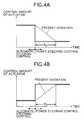
- Figs. 4A and 4Bare graphs illustrating an amount of control of the actuator when the operation is changed from the mode of the automatic steering control operation to the mode of the power steering control operation.
- a vehicle Vincludes a pair of front wheels Wf, Wf and a pair of rear wheels Wr, Wr.
- a steering wheel 1 and the front wheels Wf, Wfwhich are steering wheels, are connected together through a steering shaft 2 that rotates together with the steering wheel 1, a pinion 3 provided at a lower end of the steering shaft 2, a rack 4 meshed with the pinion 3, right and left tie rods 5, 5, provided at both ends of the rack 4, and right and left steering knuckles 6, 6, connected to the tie rods 5, 5.
- a steering actuator 7comprising an electric motor, is connected to the steering shaft 2 through a worm gear mechanism 8 in order to assist the driver in operating the steering wheel 1 or to conduct automatic steering for garaging of the vehicle which will be described below.
- a steering control unit 21comprises a controller 22 and a storage means 23.
- the controller 22receives a signal from a steering angle detecting means S 1 for detecting the steering angle ⁇ of the front wheels Wf, Wf based on the rotational angle of the steering wheel 1, a signal from a steering torque detecting means S 2 for detecting the steering torque of the steering wheel 1, signals from front wheel rotational angle detecting means S 3 , S 3 , for detecting rotational angles of the right and left front wheels Wf, Wf, a signal from a brake operation amount detecting means S 4 for detecting the operation amount of a brake pedal 9, a signal from a shift range detecting means S 5 for detecting the shift range selected by a select lever 10 ( "D" range, "R” range, “N” range, “P” range, etc.), and signals from a total of eight object detecting means S 6 mounted at a front portion, a central portion and a rear portion of the vehicle V.
- the object detecting means S 6may be any known type of detector
- a mode selecting switch S 7 and an automatic parking start switch S 8which are both operated by the driver, are connected to the controller 22.
- the mode selecting switch S 7is operated at the time of selecting any one of four parking modes, i.e., a reverse parking/right mode, a reverse parking/left mode, a longitudinal parking/right mode and a longitudinal parking/left mode, and includes four switch buttons corresponding to these modes.
- the automatic parking start switch S 8is operated to start automatic parking in any mode selected by the mode selecting switch S 7 .
- Data for the four parking modesi.e., relationships of standard steering angles ⁇ ref relative to traveling distances X of the vehicle V are stored in advance, in the storage means 23, in the form of a table.
- the traveling distance X of the vehicle Vis calculated by multiplying the peripheral length of the front wheel Wf by the rotational angle of the front wheel Wf detected by the front wheel rotational angle detecting means S 3 , S 3 .
- a high-select value, a low-select value or an average value of the pair of right and left front wheel rotational angle detecting means S 3 , S 3is used for calculating the traveling distance X.
- the controller 22controls the operation of the steering actuator 7 and the operation of an operation display device 11 which includes a liquid crystal monitor, a speaker, a lamp, a chime, a buzzer or the like, based on the signals from the detecting means S 1 to S 6 and the switches S 7 , S 8 , and the data of the parking modes stored in the storage means 23.
- an operation display device 11which includes a liquid crystal monitor, a speaker, a lamp, a chime, a buzzer or the like, based on the signals from the detecting means S 1 to S 6 and the switches S 7 , S 8 , and the data of the parking modes stored in the storage means 23.
- the steering control unit 21functions as a general power steering control unit. More specifically, when the steering wheel 1 is operated by the driver to turn the vehicle V, the steering torque detecting means S 2 detects the steering torque input to the steering wheel 1, and the controller 22 controls the operation of the steering actuator 7 based on the steering torque. As a result, the right and left front wheels Wf, Wf are steered by the driving force from the steering actuator 7, assisting the driver in executing the steering operation.
- the state where the power steering control operation is being executedcorresponds to the first control state according to the embodiment of the present invention, and the state where the automatic steering control operation is being executed corresponds to the second control state according to the embodiment of the present invention.
- the vehicle Vis moved near to a garage to be parked.
- the vehicle Vis stopped at a position (start position (1)) at which a predetermined reference point (e.g., a mark formed on the inside of the door or a left side-view mirror) is aligned with a center line of the garage.
- the mode selecting switch S 7is operated to select the reverse parking/left mode and the automatic parking start switch S 8 is turned on to start the automatic parking control operation.
- the operation display device 11displays the present position of the vehicle, obstacles surrounding the vehicle, a parking position, expected locus of movement of the vehicle from the start position to the parking position, a reversing position at which the forward movement is changed into the backward movement, etc. and, at the same time, notifies the driver of various instructions such as operations of the select lever 10 at the reversing position by voice from a speaker as well as an alarm.
- the driverloosens the brake pedal 9 and lets the vehicle V creep. Therefore, without the need of operating the steering wheel 1, the front wheels Wf, Wf are automatically steered based upon the data of the reverse parking/left mode selected by the mode selecting switch S 7 . That is, while the vehicle V moves forward from the start position (1) to the reversing position (2), the front wheels Wf, Wf are automatically steered toward the right and while the vehicle V moves backward from the reversing position (2) to a target position (3), the front wheels Wf, Wf are automatically steered toward the left.
- the data of standard steering angle ⁇ refhas been set in correspondence to the traveling distance X of the vehicle V.
- the automatic parking controlis executed while the driver is depressing the brake pedal 9 and the vehicle is creeping. Thus, in the event the driver becomes aware of an obstacle, he may quickly depress the brake pedal 9 to stop the vehicle V.
- the automatic parking controlis canceled when the driver turns the mode selecting switch S 7 off, as well as when the driver moves his foot away from the brake pedal 9, when the driver operates the steering wheel 1, or when an obstacle is detected by any one of the object detecting means S 6 . Then, the normal power steering control is resumed.
- the steering torque detection means S 2detects the steering torque produced by the steering operation of the driver, whereby the controller 22 interrupts the automatic steering control operation and changes the operation to the normal power steering control operation. This avoids interference between automatic steering and steering by the operation of the driver making it possible to quickly avoid obstacles. Besides, no particular switching operation needs be executed to discontinue the automatic steering control operation, enhancing the convenience.
- the control amount of the steering actuator 7is changed from a control amount in the automatic steering control operation to a control amount in the power steering control operation.
- the control operationis suddenly changed as indicated by the solid line in Fig. 4, the steering reaction abruptly changes while the steering wheel 1 is being operated, and the driver may feel an incompatibility.
- the control amount of the steering actuator 7decreases accompanying the change of operation from automatic steering control to power steering control
- the control amountis linearly decreased from a value of the automatic steering control down to a value of the power steering control over the passage of a predetermined period of time t o as shown in Fig. 4A, so that the steering reaction which the driver receives from the steering wheel 1, will not suddenly change.
- the control amount of the steering actuator 7increases accompanying the change of operation from automatic steering control to power steering control
- the amount of controlis linearly increased from a value of the automatic steering control up to a value of the power steering control over the passage of the predetermined period of time t o as shown in Fig. 4B, so that the steering reaction which the driver receives from the steering wheel 1 will not suddenly change.
- Thisdecreases the feeling of incompatibility which the driver may receive, and further prevents the occurrence of the steering angle becoming excessive since the steering wheel 1 suddenly becomes light or the required steering angle not being obtained since the steering wheel 1 suddenly becomes heavy.
- the predetermined period of time t ois set, for example, to about one second.
- the predetermined period of time t omay not be fixed but may be a function of the steering speed or the steering torque. That is, when the steering speed is high or the steering torque is large, i.e., when a quick steering operation is effected, the predetermined period of time t o may be shortened so that the automatic steering control operation can be quickly changed to the power steering control operation to enhance the steering response. Therefore, when the driver who has discovered an obstacle during the automatic steering control operation, quickly operates the steering wheel 1, the power steering function can be quickly effected and the obstacle can be reliably avoided.
- the steering speedis obtained as a time differentiation value of the steering angle ⁇ detected by the steering angle detecting means S 1 . Therefore, the steering angle detecting means S 1 in this embodiment also functions as a detecting means for detecting the steering speed.
- the locus of movement of the vehicle V up to the target positionhas been stored in advance in the storage means 23. It is, however, also possible to calculate the locus of movement from the present position of the vehicle V and the target position.
- the second control state in which the operation of the actuator is controlled based upon the locus of movement set by the movement locus setting meansis gradually changed to the first control state in which the operation of the actuator is controlled based upon the steering torque given to the steering wheel by the driver. Therefore, the steering reaction of the steering wheel is prevented from suddenly changing, and the driver does not feel an incompatibility.
- the second control statecan be gradually changed to the first control state relying upon a simple control operation.
- the second control stateis quickly changed to the first control state, making it possible to reliably avoid the obstacles.
Landscapes
- Engineering & Computer Science (AREA)
- Chemical & Material Sciences (AREA)
- Combustion & Propulsion (AREA)
- Transportation (AREA)
- Mechanical Engineering (AREA)
- Steering Control In Accordance With Driving Conditions (AREA)
- Power Steering Mechanism (AREA)
- Control Of Driving Devices And Active Controlling Of Vehicle (AREA)
Description
- The present invention relates to an automatic steering device forvehicles for automatically parking the vehicle without relying upon asteering operation by the driver.
- Automatic steering devices for vehicles are known inJP-A-3074256 as generic document and JP-A-4055168, for example.These automatic steering devices for vehicles utilize an actuator of awell known electric power steering system, and are designed toautomatically effect reverse parking or longitudinal parking by controllingthe actuator based on a relationship between a traveling distance of thevehicle and a steering angle, which has been stored in advance.
- According to the prior art, the driver operates the steering wheelwhile the automatic steering operation is being controlled and when it isjudged that the steering torque has exceeded a predetermined referencesteering torque, the automatic steering control operation is discontinuedand a normal power steering control operation is assumed. When theautomatic steering control operation is quickly changed to the mode ofthe power steering control operation, however, the steering reaction ofthe steering wheel suddenly decreases or increases causing the driverto feel an incompatibility.
- The present invention has been accomplished in view of theabove-mentioned circumstances, and its object is to save the driver from feeling the incompatibility when the automatic steering control operationis changed to the mode of the power steering control operation.
- In order to accomplish the above-mentioned object, the present invention isconcerned with an automatic steering device for vehicles according to
claim 1. The device comprises an actuator for steering wheels of the vehicle; amovement locus setting means for storing or calculating a locus of movementof a vehicle up to a target position; and a control means for changingbetween a first control state for controlling the operation of the actuatorbased on a steering torque exerted by a driver on a vehicle steering- wheel and a second control state for controlling the operation of theactuator based on the locus of movement set by the movement locussetting means. The control means gradually changes the secondcontrol state to the first control state. Accordingly, the second controlstate in which the driving of the actuator is controlled based upon thelocus of movement set by the movement locus setting means, isgradually changed to the first control state in which the operation of theactuator is controlled based upon the steering torque exerted to thesteering wheel by the driver. Therefore, the steering reaction of thesteering wheel is prevented from suddenly changing, and thus, the driverfeels more compatibility. - The second control state is changedto the first control state by changing a control amount of the actuator inthe second control state up to a control amount of the actuator in the firstcontrol state over a predetermined period of time. The second controlstate can thus be gradually changed to the first control state relying on asimple control operation. The requiredtime has been set to be one second, which, however, can be changeddepending upon the design requirements.
- Preferably, a detection means detects a steering speedor a steering torque, and the rate of changing the second control stateto the first control state is increased depending upon the steering speedor the steering torque that is detected. Thus, when the driver quicklymanipulates the steering wheel in an attempt to avoid obstacles, thesecond control state is quickly changed to the first control state, makingit possible to reliably avoid the obstacles.
- An embodiment for carrying out the present invention will now bedescribed by way of an example shown in the accompanying drawings.
- Fig. 1 is a diagram illustrating a vehicle equipped with a steeringcontrol device according to the embodiment of the present invention.
- Figs. 2A and 2B are diagrams illustrating the operation of reverseparking/left mode.
- Fig. 3 is a diagram illustrating mode selecting switches and anautomatic parking start switch.
- Figs. 4A and 4B are graphs illustrating an amount of control of theactuator when the operation is changed from the mode of the automaticsteering control operation to the mode of the power steering controloperation.
- As shown in Fig. 1, a vehicle V includes a pair of front wheels Wf,Wf and a pair of rear wheels Wr, Wr. A
steering wheel 1 and the frontwheels Wf, Wf which are steering wheels, are connected togetherthrough asteering shaft 2 that rotates together with thesteering wheel 1,apinion 3 provided at a lower end of thesteering shaft 2, arack 4 meshed with thepinion 3, right andleft tie rods rack 4, and right andleft steering knuckles tie rods steering actuator 7 comprising an electric motor, isconnected to thesteering shaft 2 through aworm gear mechanism 8 inorder to assist the driver in operating thesteering wheel 1 or to conductautomatic steering for garaging of the vehicle which will be describedbelow. - A
steering control unit 21 comprises acontroller 22 and a storagemeans 23. Thecontroller 22 receives a signal from a steering angledetecting means S1 for detecting the steering angle of the front wheelsWf, Wf based on the rotational angle of thesteering wheel 1, a signalfrom a steering torque detecting means S2 for detecting the steeringtorque of thesteering wheel 1, signals from front wheel rotational angledetecting means S3, S3, for detecting rotational angles of the right andleft front wheels Wf, Wf, a signal from a brake operation amountdetecting means S4 for detecting the operation amount of a brake pedal9, a signal from a shift range detecting means S5 for detecting the shiftrange selected by a select lever 10 ( "D" range, "R" range, "N" range,"P" range, etc.), and signals from a total of eight object detecting meansS6 mounted at a front portion, a central portion and a rear portion of thevehicle V. The object detecting means S6 may be any known type ofdetector such as sonar, radar, television camera or the like. Linesconnecting the eight object detecting means S6 and thecontroller 22 areomitted to simplify the drawing. - A mode selecting switch S7 and an automatic parking start switchS8, which are both operated by the driver, are connected to the
controller 22. As will be obvious from Fig. 3, the mode selecting switch S7 isoperated at the time of selecting any one of four parking modes, i.e., areverse parking/right mode, a reverse parking/left mode, a longitudinal parking/right mode and a longitudinal parking/left mode, and includesfour switch buttons corresponding to these modes. The automaticparking start switch S8 is operated to start automatic parking in anymode selected by the mode selecting switch S7. - Data for the four parking modes, i.e., relationships of standardsteering angles ref relative to traveling distances X of the vehicle V arestored in advance, in the storage means 23, in the form of a table. Thetraveling distance X of the vehicle V, is calculated by multiplying theperipheral length of the front wheel Wf by the rotational angle of the frontwheel Wf detected by the front wheel rotational angle detecting meansS3, S3. A high-select value, a low-select value or an average value ofthe pair of right and left front wheel rotational angle detecting means S3,S3 is used for calculating the traveling distance X.
- The
controller 22 controls the operation of thesteering actuator 7and the operation of an operation display device 11 which includes aliquid crystal monitor, a speaker, a lamp, a chime, a buzzer or the like,based on the signals from the detecting means S1 to S6 and theswitches S7, S8, and the data of the parking modes stored in the storagemeans 23. - The operation of the embodiment of the present invention havingthe above-described arrangement will be described below.
- When the vehicle is in a normal state in which automatic parkingis not carried out (when the automatic parking start switch S8 is notturned on), the
steering control unit 21 functions as a general powersteering control unit. More specifically, when thesteering wheel 1 isoperated by the driver to turn the vehicle V, the steering torque detectingmeans S2 detects the steering torque input to thesteering wheel 1, andthecontroller 22 controls the operation of thesteering actuator 7 basedon the steering torque. As a result, the right and left front wheels Wf, Wf are steered by the driving force from thesteering actuator 7, assistingthe driver in executing the steering operation. The state where thepower steering control operation is being executed corresponds to thefirst control state according to the embodiment of the present invention,and the state where the automatic steering control operation is beingexecuted corresponds to the second control state according to theembodiment of the present invention. - Next, automatic parking control will be described with reference tothe reverse parking/left mode (mode in which the vehicle V moves backto a parking position on the left side of the vehicle V).
- First, as shown in Fig. 2A, the vehicle V is moved near to agarage to be parked. In a state in which the left side of the vehicle bodyis located as close as possible to the entrance line of the garage, thevehicle V is stopped at a position (start position (1)) at which apredetermined reference point (e.g., a mark formed on the inside of thedoor or a left side-view mirror) is aligned with a center line of the garage.The mode selecting switch S7 is operated to select the reverseparking/left mode and the automatic parking start switch S8 is turned onto start the automatic parking control operation. While the automaticparking control operation is being carried out, the operation displaydevice 11 displays the present position of the vehicle, obstaclessurrounding the vehicle, a parking position, expected locus of movementof the vehicle from the start position to the parking position, a reversingposition at which the forward movement is changed into the backwardmovement, etc. and, at the same time, notifies the driver of variousinstructions such as operations of the
select lever 10 at the reversingposition by voice from a speaker as well as an alarm. - Owing to the automatic parking control operation, the driverloosens the brake pedal 9 and lets the vehicle V creep. Therefore, without the need of operating the
steering wheel 1, the front wheels Wf,Wf are automatically steered based upon the data of the reverseparking/left mode selected by the mode selecting switch S7. That is,while the vehicle V moves forward from the start position (1) to thereversing position (2), the front wheels Wf, Wf are automatically steeredtoward the right and while the vehicle V moves backward from thereversing position (2) to a target position (3), the front wheels Wf, Wf areautomatically steered toward the left. - As can be seen from Fig. 2B, while the automatic steering is beingcarried out, the
controller 22 calculates a deviation E = (ref - ) basedon the standard steering angle ref in the reverse parking/left mode,read out from the storage means 23 and the steering angle inputtedfrom the steering angle detecting means S1, and controls the operationof thesteering actuator 7, so that the deviation E becomes 0. At thistime, the data of standard steering angle ref has been set incorrespondence to the traveling distance X of the vehicle V. Hence,despite that there is a small variation in the vehicle speed during thecreeping of the vehicle, the vehicle V always moves along theabove-described locus of movement. - The automatic parking control is executed while the driver isdepressing the brake pedal 9 and the vehicle is creeping. Thus, in theevent the driver becomes aware of an obstacle, he may quickly depressthe brake pedal 9 to stop the vehicle V.
- The automatic parking control is canceled when the driver turnsthe mode selecting switch S7 off, as well as when the driver moves hisfoot away from the brake pedal 9, when the driver operates the
steeringwheel 1, or when an obstacle is detected by any one of the objectdetecting means S6. Then, the normal power steering control isresumed. - Further, described below is the situation when the driver operatesthe
steering wheel 1 to discontinue the automatic parking control. Whenthe driver has discovered an obstacle during the automatic steeringcontrol operation or when the driver wishes to change his course, hemay operate thesteering wheel 1. Then, the steering torque detectionmeans S2 detects the steering torque produced by the steering operationof the driver, whereby thecontroller 22 interrupts the automatic steeringcontrol operation and changes the operation to the normal powersteering control operation. This avoids interference between automaticsteering and steering by the operation of the driver making it possible toquickly avoid obstacles. Besides, no particular switching operationneeds be executed to discontinue the automatic steering controloperation, enhancing the convenience. - When the automatic steering control operation is changed to thepower steering control operation as a result of the fact that the driver hasoperated the
steering wheel 1 during the automatic steering controloperation, the control amount of thesteering actuator 7 is changed froma control amount in the automatic steering control operation to a controlamount in the power steering control operation. When the controloperation is suddenly changed as indicated by the solid line in Fig. 4, thesteering reaction abruptly changes while thesteering wheel 1 is beingoperated, and the driver may feel an incompatibility. - When the control amount of the
steering actuator 7 decreasesaccompanying the change of operation from automatic steering controlto power steering control, the control amount is linearly decreased froma value of the automatic steering control down to a value of the powersteering control over the passage of a predetermined period of time to asshown in Fig. 4A, so that the steering reaction which the driver receivesfrom thesteering wheel 1, will not suddenly change. When the control amount of thesteering actuator 7 increases accompanying the changeof operation from automatic steering control to power steering control,the amount of control is linearly increased from a value of the automaticsteering control up to a value of the power steering control over thepassage of the predetermined period of time to as shown in Fig. 4B, sothat the steering reaction which the driver receives from thesteeringwheel 1 will not suddenly change. This decreases the feeling ofincompatibility which the driver may receive, and further prevents theoccurrence of the steering angle becoming excessive since thesteeringwheel 1 suddenly becomes light or the required steering angle not beingobtained since thesteering wheel 1 suddenly becomes heavy. - When the predetermined period of time to is too short, the steeringreaction suddenly changes and the effect is not obtained to a sufficientdegree. When the predetermined period of time to is too long, on theother hand, the proper power steering control operation is not quicklyassumed. It is therefore desired that the predetermined period of time tois set, for example, to about one second.
- The predetermined period of time to may not be fixed but may bea function of the steering speed or the steering torque. That is, when thesteering speed is high or the steering torque is large, i.e., when a quicksteering operation is effected, the predetermined period of time to maybe shortened so that the automatic steering control operation can bequickly changed to the power steering control operation to enhance thesteering response. Therefore, when the driver who has discovered anobstacle during the automatic steering control operation, quicklyoperates the
steering wheel 1, the power steering function can bequickly effected and the obstacle can be reliably avoided. - The steering speed is obtained as a time differentiation value ofthe steering angle detected by the steering angle detecting means S1. Therefore, the steering angle detecting means S1 in this embodimentalso functions as a detecting means for detecting the steering speed.
- In the above embodiment, the locus of movement of the vehicle Vup to the target position has been stored in advance in the storagemeans 23. It is, however, also possible to calculate the locus ofmovement from the present position of the vehicle V and the targetposition.
- According to the present invention, the second control state inwhich the operation of the actuator is controlled based upon the locus ofmovement set by the movement locus setting means, is graduallychanged to the first control state in which the operation of the actuator iscontrolled based upon the steering torque given to the steering wheel bythe driver. Therefore, the steering reaction of the steering wheel isprevented from suddenly changing, and the driver does not feel anincompatibility.
- The second control state can be gradually changed to the firstcontrol state relying upon a simple control operation.
- Further, when the driver has quickly operated the steering wheelto avoid obstacles, the second control state is quickly changed to thefirst control state, making it possible to reliably avoid the obstacles.
Claims (2)
- An automatic steering device for a vehicle comprising:an actuator (7) for steering wheels (Wf) of the vehicle (V);a movement locus setting means (23) for storing or calculating a locusof movement of the vehicle to a target position; anda control means (22) coupled to the actuator (7) and the movementlocus setting means (23) for changing between a first control state forcontrolling the operation of the actuator (7) based on a steering torqueexerted by a driver on a vehicle steering wheel (1) and a secondcontrol state for controlling the operation of the actuator (7) based onthe locus of movement set by the movement locus setting means (23),characterized in that the control means (22) can gradually change thesecond control state to the first control state by changing a control amount of the actuator (7)in the second control state to a control amount of theactuator (7) in the first control state over a predeterminedperiod of time (to).
- An automatic steering device according to claim 1,including detection means (S1,S2) coupled to the control means (22),for detecting a steering speed or a steering torque on the steeringwheel (1), wherein the rate of changing the second control state to thefirst control state is increased depending upon the steering speed orthe steering torque that is detected.
Applications Claiming Priority (3)
| Application Number | Priority Date | Filing Date | Title |
|---|---|---|---|
| JP24068597 | 1997-09-05 | ||
| JP24068597AJP3311277B2 (en) | 1997-09-05 | 1997-09-05 | Automatic vehicle steering system |
| JP240685/97 | 1997-09-05 |
Publications (3)
| Publication Number | Publication Date |
|---|---|
| EP0900712A2 EP0900712A2 (en) | 1999-03-10 |
| EP0900712A3 EP0900712A3 (en) | 2000-05-24 |
| EP0900712B1true EP0900712B1 (en) | 2002-07-24 |
Family
ID=17063192
Family Applications (1)
| Application Number | Title | Priority Date | Filing Date |
|---|---|---|---|
| EP98116474AExpired - LifetimeEP0900712B1 (en) | 1997-09-05 | 1998-09-01 | Automatic steering device for vehicules |
Country Status (4)
| Country | Link |
|---|---|
| US (1) | US6154695A (en) |
| EP (1) | EP0900712B1 (en) |
| JP (1) | JP3311277B2 (en) |
| DE (1) | DE69806701T2 (en) |
Cited By (1)
| Publication number | Priority date | Publication date | Assignee | Title |
|---|---|---|---|---|
| US20240400089A1 (en)* | 2023-06-01 | 2024-12-05 | Qualcomm Incorporated | Attack-sustain-release (asr) envelopes for intuitive tuning of collaborative driving features |
Families Citing this family (38)
| Publication number | Priority date | Publication date | Assignee | Title |
|---|---|---|---|---|
| DE69730570T2 (en)* | 1996-10-09 | 2005-02-03 | Honda Giken Kogyo K.K. | Automatic steering system for a vehicle |
| EP1050866B1 (en)* | 1999-04-28 | 2003-07-09 | Matsushita Electric Industrial Co., Ltd. | Parking assistance device and method |
| JP4057743B2 (en)* | 1999-05-26 | 2008-03-05 | 本田技研工業株式会社 | Vehicle steering device |
| US7366595B1 (en) | 1999-06-25 | 2008-04-29 | Seiko Epson Corporation | Vehicle drive assist system |
| JP3498910B2 (en)* | 2000-09-05 | 2004-02-23 | 日産自動車株式会社 | Lane tracking controller |
| US6625530B1 (en)* | 2000-11-06 | 2003-09-23 | Delphi Technologies, Inc. | Feed forward—feed back control for steer-by-wire system |
| EP1399348B1 (en)* | 2001-06-08 | 2009-08-19 | Delphi Technologies, Inc. | Velocity compensation control for electric steering systems |
| WO2003026120A2 (en)* | 2001-09-14 | 2003-03-27 | Delphi Technologies, Inc. | Complementary force and position control for an automotive steering system |
| US20030150366A1 (en)* | 2002-02-13 | 2003-08-14 | Kaufmann Timothy W. | Watercraft steer-by-wire system |
| US20040189228A1 (en)* | 2003-03-28 | 2004-09-30 | Gregory Katch | Vehicle speed dependent compensator for electric steering systems |
| JP4057954B2 (en)* | 2003-05-28 | 2008-03-05 | 本田技研工業株式会社 | Automatic vehicle steering system |
| DE102005061909A1 (en)* | 2005-12-23 | 2007-07-05 | Volkswagen Ag | Park steering assistance system and method for operating a park steering assistance system |
| JP4895003B2 (en)* | 2006-01-25 | 2012-03-14 | 株式会社エクォス・リサーチ | Automatic operation control device |
| JP2007196808A (en)* | 2006-01-25 | 2007-08-09 | Equos Research Co Ltd | Automatic operation control device |
| US8538631B2 (en)* | 2007-01-23 | 2013-09-17 | GM Global Technology Operations LLC | Method and system for vehicle parking assistance |
| JP4609444B2 (en)* | 2007-03-08 | 2011-01-12 | トヨタ自動車株式会社 | Parking assistance device |
| JP5444748B2 (en)* | 2009-02-18 | 2014-03-19 | 日産自動車株式会社 | Steering device and steering control method |
| DE102009047262A1 (en)* | 2009-11-30 | 2011-06-01 | Robert Bosch Gmbh | Method for displaying a parking process |
| US8509993B2 (en) | 2010-04-19 | 2013-08-13 | Gm Global Technology Operations, Inc | Systems and methods for controlling a vehicle along a road with a road bank |
| CN104995082B (en)* | 2013-02-19 | 2016-12-07 | 丰田自动车株式会社 | Collision avoidance assistance device and collision avoidance assistance method |
| JP6187090B2 (en)* | 2013-09-25 | 2017-08-30 | 日産自動車株式会社 | Vehicle operation control device and vehicle operation control method |
| JP6171976B2 (en)* | 2014-02-25 | 2017-08-02 | 株式会社デンソー | Vehicle behavior control device |
| JP6129800B2 (en) | 2014-09-12 | 2017-05-17 | アイシン精機株式会社 | Parking assistance device |
| JP6379907B2 (en)* | 2014-09-16 | 2018-08-29 | 株式会社ジェイテクト | Electric power steering device |
| EP3210855B1 (en)* | 2014-12-02 | 2020-02-19 | NSK Ltd. | Electric power steering device |
| BR112017011293A2 (en)* | 2014-12-02 | 2018-10-09 | Nsk Ltd. | electric power steering device |
| JP6004146B1 (en) | 2014-12-02 | 2016-10-05 | 日本精工株式会社 | Electric power steering device |
| JP6237958B2 (en)* | 2015-06-12 | 2017-11-29 | 日本精工株式会社 | Electric power steering device |
| JP6332168B2 (en)* | 2015-06-26 | 2018-05-30 | 株式会社デンソー | Lane departure control device |
| JP6663767B2 (en)* | 2016-03-25 | 2020-03-13 | 株式会社Subaru | Vehicle steering assist device |
| JP6345225B1 (en)* | 2016-12-21 | 2018-06-20 | 三菱電機株式会社 | Vehicle steering system and lane keeping system |
| KR102485666B1 (en)* | 2018-10-26 | 2023-01-06 | 현대모비스 주식회사 | Apparatus for controlling motor driven power steering system and method thereof |
| JP7169938B2 (en)* | 2019-05-07 | 2022-11-11 | 株式会社クボタ | work vehicle |
| KR102667920B1 (en)* | 2019-07-10 | 2024-05-22 | 현대모비스 주식회사 | Apparatus for steering by wire of vehicle and control method thereof |
| CN111216716B (en)* | 2020-02-17 | 2021-09-03 | 威马智慧出行科技(上海)有限公司 | Automatic parking driver intervention response method, electronic device and automobile |
| JP7391475B2 (en)* | 2020-03-12 | 2023-12-05 | ダイハツ工業株式会社 | Steering support device |
| KR102341112B1 (en)* | 2020-04-23 | 2021-12-21 | 현대모비스 주식회사 | Apparatus for controlling motor driven power steering system and method thereof |
| KR20250018791A (en)* | 2023-07-31 | 2025-02-07 | 현대자동차주식회사 | Apparatus for controlling autonomous driving and method thereof |
Family Cites Families (9)
| Publication number | Priority date | Publication date | Assignee | Title |
|---|---|---|---|---|
| US4219093A (en)* | 1978-08-04 | 1980-08-26 | Zahnradfabrik Friedrichshafen Ag | Vehicle steering assist |
| US4735274A (en)* | 1985-11-22 | 1988-04-05 | Good Warren T | Automatic parallel parking system |
| US4931930A (en)* | 1988-04-19 | 1990-06-05 | Industrial Technology Research Institute | Automatic parking device for automobile |
| JPH0374256A (en)* | 1989-06-08 | 1991-03-28 | Fuji Heavy Ind Ltd | Electric power steering and concurrently automatic steering device for automobile |
| JPH0455168A (en)* | 1990-06-15 | 1992-02-21 | Hitachi Ltd | Steering device and automatic steering system |
| JP2998864B2 (en)* | 1991-12-25 | 2000-01-17 | アイシン精機株式会社 | Automatic vehicle steering control device |
| US5742141A (en)* | 1996-06-04 | 1998-04-21 | Ford Motor Company | Semi-autonomous parking control system for a vehicle providing tactile feedback to a vehicle operator |
| DE19650808A1 (en)* | 1996-12-06 | 1998-06-10 | Bosch Gmbh Robert | Parking device for a motor vehicle |
| JPH10309961A (en)* | 1997-05-12 | 1998-11-24 | Toyota Motor Corp | Automatic driving vehicle control device |
- 1997
- 1997-09-05JPJP24068597Apatent/JP3311277B2/ennot_activeExpired - Fee Related
- 1998
- 1998-09-01DEDE69806701Tpatent/DE69806701T2/ennot_activeExpired - Lifetime
- 1998-09-01EPEP98116474Apatent/EP0900712B1/ennot_activeExpired - Lifetime
- 1998-09-03USUS09/146,140patent/US6154695A/ennot_activeExpired - Lifetime
Cited By (1)
| Publication number | Priority date | Publication date | Assignee | Title |
|---|---|---|---|---|
| US20240400089A1 (en)* | 2023-06-01 | 2024-12-05 | Qualcomm Incorporated | Attack-sustain-release (asr) envelopes for intuitive tuning of collaborative driving features |
Also Published As
| Publication number | Publication date |
|---|---|
| JPH1178940A (en) | 1999-03-23 |
| JP3311277B2 (en) | 2002-08-05 |
| US6154695A (en) | 2000-11-28 |
| DE69806701D1 (en) | 2002-08-29 |
| EP0900712A2 (en) | 1999-03-10 |
| DE69806701T2 (en) | 2002-11-14 |
| EP0900712A3 (en) | 2000-05-24 |
Similar Documents
| Publication | Publication Date | Title |
|---|---|---|
| EP0900712B1 (en) | Automatic steering device for vehicules | |
| US5957232A (en) | Automatic steering system for vehicle | |
| US6212452B1 (en) | Automatic steering system for vehicle | |
| US6059063A (en) | Automatic steering system for vehicle | |
| EP0849144B1 (en) | Automatic steering apparatus for vehicles | |
| EP0835796B1 (en) | Automatic steering system for verhicle | |
| US6275754B1 (en) | Automatic steering system for vehicle | |
| US7953531B2 (en) | Automatic steering device for vehicle | |
| EP0835797B1 (en) | Automatic steering system for vehicle | |
| US6102147A (en) | Automatic steering system for vehicle | |
| JP4109798B2 (en) | Automatic vehicle steering system | |
| JP3266828B2 (en) | Automatic vehicle steering system | |
| US6018692A (en) | Automatic steering apparatus for vehicles | |
| US5931252A (en) | Automatic steering system for vehicle | |
| JP3881775B2 (en) | Automatic vehicle steering system | |
| JP3881776B2 (en) | Automatic vehicle steering system | |
| EP0931712B1 (en) | Automatic steering system in vehicle | |
| JP3866403B2 (en) | Automatic vehicle steering system | |
| JP3138804B2 (en) | Automatic vehicle steering system | |
| JP4110040B2 (en) | Automatic vehicle steering system | |
| US5931253A (en) | Automatic steering system for vehicle | |
| JP4092044B2 (en) | Automatic vehicle steering system | |
| JP2004351999A (en) | Automatic vehicle steering system | |
| JPH11208495A (en) | Automatic vehicle steering system |
Legal Events
| Date | Code | Title | Description |
|---|---|---|---|
| PUAI | Public reference made under article 153(3) epc to a published international application that has entered the european phase | Free format text:ORIGINAL CODE: 0009012 | |
| AK | Designated contracting states | Kind code of ref document:A2 Designated state(s):DE FR GB | |
| AX | Request for extension of the european patent | Free format text:AL;LT;LV;MK;RO;SI | |
| PUAL | Search report despatched | Free format text:ORIGINAL CODE: 0009013 | |
| AK | Designated contracting states | Kind code of ref document:A3 Designated state(s):AT BE CH CY DE DK ES FI FR GB GR IE IT LI LU MC NL PT SE | |
| AX | Request for extension of the european patent | Free format text:AL;LT;LV;MK;RO;SI | |
| 17P | Request for examination filed | Effective date:20000626 | |
| 17Q | First examination report despatched | Effective date:20000904 | |
| AKX | Designation fees paid | Free format text:DE FR GB | |
| GRAG | Despatch of communication of intention to grant | Free format text:ORIGINAL CODE: EPIDOS AGRA | |
| GRAG | Despatch of communication of intention to grant | Free format text:ORIGINAL CODE: EPIDOS AGRA | |
| GRAH | Despatch of communication of intention to grant a patent | Free format text:ORIGINAL CODE: EPIDOS IGRA | |
| GRAH | Despatch of communication of intention to grant a patent | Free format text:ORIGINAL CODE: EPIDOS IGRA | |
| GRAA | (expected) grant | Free format text:ORIGINAL CODE: 0009210 | |
| AK | Designated contracting states | Kind code of ref document:B1 Designated state(s):DE FR GB | |
| REG | Reference to a national code | Ref country code:GB Ref legal event code:FG4D | |
| REF | Corresponds to: | Ref document number:69806701 Country of ref document:DE Date of ref document:20020829 | |
| ET | Fr: translation filed | ||
| PLBE | No opposition filed within time limit | Free format text:ORIGINAL CODE: 0009261 | |
| STAA | Information on the status of an ep patent application or granted ep patent | Free format text:STATUS: NO OPPOSITION FILED WITHIN TIME LIMIT | |
| 26N | No opposition filed | Effective date:20030425 | |
| PGFP | Annual fee paid to national office [announced via postgrant information from national office to epo] | Ref country code:FR Payment date:20050823 Year of fee payment:8 | |
| PGFP | Annual fee paid to national office [announced via postgrant information from national office to epo] | Ref country code:GB Payment date:20050831 Year of fee payment:8 | |
| GBPC | Gb: european patent ceased through non-payment of renewal fee | Effective date:20060901 | |
| REG | Reference to a national code | Ref country code:FR Ref legal event code:ST Effective date:20070531 | |
| PG25 | Lapsed in a contracting state [announced via postgrant information from national office to epo] | Ref country code:GB Free format text:LAPSE BECAUSE OF NON-PAYMENT OF DUE FEES Effective date:20060901 | |
| PG25 | Lapsed in a contracting state [announced via postgrant information from national office to epo] | Ref country code:FR Free format text:LAPSE BECAUSE OF NON-PAYMENT OF DUE FEES Effective date:20061002 | |
| REG | Reference to a national code | Ref country code:DE Ref legal event code:R084 Ref document number:69806701 Country of ref document:DE Effective date:20120523 | |
| PGFP | Annual fee paid to national office [announced via postgrant information from national office to epo] | Ref country code:DE Payment date:20140827 Year of fee payment:17 | |
| REG | Reference to a national code | Ref country code:DE Ref legal event code:R119 Ref document number:69806701 Country of ref document:DE | |
| PG25 | Lapsed in a contracting state [announced via postgrant information from national office to epo] | Ref country code:DE Free format text:LAPSE BECAUSE OF NON-PAYMENT OF DUE FEES Effective date:20160401 |