EP0899578B1 - Method of localising the position of a fixed terminal employing a constellation of satellites - Google Patents
Method of localising the position of a fixed terminal employing a constellation of satellitesDownload PDFInfo
- Publication number
- EP0899578B1 EP0899578B1EP98402097AEP98402097AEP0899578B1EP 0899578 B1EP0899578 B1EP 0899578B1EP 98402097 AEP98402097 AEP 98402097AEP 98402097 AEP98402097 AEP 98402097AEP 0899578 B1EP0899578 B1EP 0899578B1
- Authority
- EP
- European Patent Office
- Prior art keywords
- terminal
- satellite
- satellites
- active
- estimated position
- Prior art date
- Legal status (The legal status is an assumption and is not a legal conclusion. Google has not performed a legal analysis and makes no representation as to the accuracy of the status listed.)
- Expired - Lifetime
Links
- 238000000034methodMethods0.000titleclaimsdescription38
- 230000005540biological transmissionEffects0.000claimsdescription7
- 230000002123temporal effectEffects0.000claimsdescription2
- 230000004807localizationEffects0.000description33
- 238000004891communicationMethods0.000description6
- 238000010586diagramMethods0.000description6
- 238000009434installationMethods0.000description4
- 230000001360synchronised effectEffects0.000description3
- 238000012550auditMethods0.000description2
- 230000000295complement effectEffects0.000description1
- 238000012937correctionMethods0.000description1
- 230000001955cumulated effectEffects0.000description1
- 238000005259measurementMethods0.000description1
- 238000011160researchMethods0.000description1
Images


Classifications
- G—PHYSICS
- G01—MEASURING; TESTING
- G01S—RADIO DIRECTION-FINDING; RADIO NAVIGATION; DETERMINING DISTANCE OR VELOCITY BY USE OF RADIO WAVES; LOCATING OR PRESENCE-DETECTING BY USE OF THE REFLECTION OR RERADIATION OF RADIO WAVES; ANALOGOUS ARRANGEMENTS USING OTHER WAVES
- G01S5/00—Position-fixing by co-ordinating two or more direction or position line determinations; Position-fixing by co-ordinating two or more distance determinations
- G01S5/02—Position-fixing by co-ordinating two or more direction or position line determinations; Position-fixing by co-ordinating two or more distance determinations using radio waves
- G01S5/12—Position-fixing by co-ordinating two or more direction or position line determinations; Position-fixing by co-ordinating two or more distance determinations using radio waves by co-ordinating position lines of different shape, e.g. hyperbolic, circular, elliptical or radial
- G—PHYSICS
- G01—MEASURING; TESTING
- G01S—RADIO DIRECTION-FINDING; RADIO NAVIGATION; DETERMINING DISTANCE OR VELOCITY BY USE OF RADIO WAVES; LOCATING OR PRESENCE-DETECTING BY USE OF THE REFLECTION OR RERADIATION OF RADIO WAVES; ANALOGOUS ARRANGEMENTS USING OTHER WAVES
- G01S5/00—Position-fixing by co-ordinating two or more direction or position line determinations; Position-fixing by co-ordinating two or more distance determinations
- G01S5/0009—Transmission of position information to remote stations
- G01S5/0018—Transmission from mobile station to base station
Definitions
- the field of the inventionis that of telecommunications systems by satellites.
- a satellite communications systemincludes in particular a constellation of non-geostationary satellites (consisting for example of 64 low-orbit satellites), a plurality of base stations (or “Gateway Stations” in English), as well as a plurality of fixed terminals.
- Each base stationis associated with a separate geographic unit (or “spot") and is linked to a terrestrial network of telecommunication.
- Each terminalcommunicates, via satellites, with the base (and therefore with the terrestrial telecommunication network) of the cell in which it is.
- Each satellitewhen active vis-à-vis a base station, receives from it information which it retransmits to the fixed terminal (s) present in its coverage area.
- each satellitewhen active vis-à-vis a base station, retransmits thereto the information it receives from each fixed terminal present in its coverage area.
- a satellitecannot be active with respect to a base station only if it is within visibility of the latter.
- the inventionrelates to a method for locating a terminal landline of such satellite communications system.
- each fixed terminal of the systemit is indeed necessary to know the position of each fixed terminal of the system. For example, this allows you to synchronize the fixed terminals, so as to avoid or reduce interference, upon reception by the satellites, between signals transmitted by different fixed terminals. It also allows determine the tariff zone to which each fixed terminal belongs.
- the terminal considered hereis fixed. Its location is therefore performed during its initial installation, or during each new installation if the terminal is moved (for example from one house to another).
- a first known solutionconsists in implement in this latter a receiver of one of the known localization systems, such than the GPS system (for "Global Positioning System” in English) or GLONASS (for "Global Navigation Satellite System”.
- GPS systemfor "Global Positioning System” in English
- GLONASSfor "Global Navigation Satellite System”.
- This first known solutionhas the major drawback of being very expensive. Indeed, a GPS or GLONASS type receiver has too high a cost vis-à-vis the price of a fixed terminal "general public". In addition, because the location of the fixed terminal is only performed at installation, adding a receiver to the fixed terminal specialized location represents an excessive investment for its use done.
- a second known solutionconsists in implementing, using the existing infrastructure (that is to say in particular with the fixed terminal that one seeks to locate and some satellites of the constellation), a known localization technique, to type AOA (for "Angle Of Arrival” in English) or TDOA (for "Time Difference Of Arrived "in English).
- the position of the terminalis determined by combining angles of arrival of signals from different satellites.
- the terminal positionis determined by combining differences in arrival time of signals from different satellites.
- this second known solutiondoes not require any specialized location receiver (GPS type or GLONASS).
- the inventionparticularly aims to overcome these various drawbacks of the state of the art.
- one of the objectives of the present inventionis to provide a method for locating a fixed terminal of a telecommunications system by satellites, this method being simple to implement and inexpensive.
- the inventionalso aims to provide such a method not requiring the implementation in the fixed terminal of a specialized location receiver (of the type GPS or GLONASS).
- Another object of the inventionis to provide such a method using existing system infrastructure without imposing harsh conditions on the terminal fixed (no precise azimuth reference) or to satellites (the latter need not be synchronous).
- a method of improving the location accuracy of a fixed terminal of a satellite telecommunications systemcomprising a constellation of satellites, a plurality of base stations, each associated with a separate geographic cell and connected to a terrestrial telecommunications network, and a plurality of fixed terminals, one or more satellite (s) being said to be active vis-à-vis a given base station when it (s) is (are) in visibility thereof, each active satellite which receives information from the base station vis-à-vis which it is active retransmitting it to the fixed terminal or terminals present in its coverage area, each active satellite receiving information from a fixed terminal present in its coverage area coverage retransmitting them to the base station vis-à-vis which it is active,
- the localization method according to the present inventiontherefore comprises a phase of "average” location, for example ⁇ 300 m.
- the general principle of this phase of "average” locationconsists, for the terminal, of calculating the intersection of at least three hyperboloids on which it is located, assuming already known an estimate of its "coarse” position (for example ⁇ 100 km).
- each hyperboloid of the inventiondoes not correspond to a real image of the system since it is not calculated according to the position, at a given single instant, of the first and second satellites.
- each hyperboloid of the inventioncorresponds to an image fictitious system, taking into account on the one hand the position p1, at a first given moment t1, of the first satellite and on the other hand of the position p2, at a second given time t2, of the second satellite.
- the only condition imposed by the inventionis that the instants t1 'and t2' of reception by the terminal are equal or close to each other (for example offset from a few milliseconds), so that the estimate of (t2 '- t1') is correct despite the fact that the terminal clock is not very precise compared to that of each of the satellites.
- the number of satellites requireddiffers according to the number of satellites that the terminal is able to listen to simultaneously. For example, if the terminal is able to listen to three satellites simultaneously, it can receive, at times t1 ', t2' and t3 'close or equal, information from these three satellites, and calculate the following three hyperboloids: H 1,2 , H 1,3 and H 2,3 , where the hyperboloid H i, j is calculated using the i-th and j-th satellites. On the other hand, if the terminal is only able to listen to two satellites simultaneously, then the calculation of the following three hyperboloids: H 1.2 , H 3.4 and H 5.6 requires six separate satellites.
- said “average” localization phasefurther comprises the following step: -vi- using the previous "average” estimated position in place of said "rough” estimated position, said terminal repeats steps -i- to -v- at least once, so as to obtain a new estimated "average” position ".
- the base stationtransmits said first and second information with a temporal precompensation such as after retransmission by said first and second satellites, said first and second information are received substantially simultaneously by said base station.
- the terminalcan approximately point (but sufficiently) on any satellite entering the spot By following this satellite, the terminal is kept informed of any inter-satellite jump. So during the jump inter-satellite, which usually lasts a few seconds, the terminal has two satellites (one incoming and one outgoing) active simultaneously.
- each terminalcomprises reception means simultaneous information from at least two separate satellites.
- said means for simultaneously receiving information transmitted by at least two separate satellitesinclude at least two directional antennas each pointed at a separate satellite.
- the location method according to the present inventiontherefore also comprises a "coarse” location phase, for example ⁇ 100 km.
- the general principle of this "rough" location phaseconsists, for the terminal, of calculating the intersection at least three isoelevation surfaces on which it is located.
- step -b-assumes that the ephemeris of each of the satellites of the constellation is known to the system. Furthermore, step -c- assumes that the terminal knows the angle of elevation ⁇ of its antenna relative to the ground. This can be considered in placing the terminal horizontally.
- At least onehas an azimuth ⁇ , seen by said terminal, at least 10 ° from the azimuths of the other two satellites.
- said two directional antennasrotate at the same elevation, each covering approximately 180 ° around the angle azimuth ⁇ .
- each antennacovers, in a complementary way with the other antenna, a half-turn, and we therefore minimize the time necessary to scan on a turn complete (that is to say for the azimuth 0 varying from 0 to 2 ⁇ ).
- the localization method according to the present inventiontherefore comprises a phase "fine” location, for example ⁇ 60 m.
- the general principle of this phase of "fine” localizationconsists in calculating the time advance (or “Timing Advance” in English) that the terminal presents with respect to the time station, or more precisely the time advance presented by the signals from the terminal (via the active satellite) when received by the base station.
- this "fine” localization phaseis active and not passive.
- the terminalenters here in communication, via an active satellite, with the cell's base station where it is located. This entry into communication is done for example at particular times, reserved during light traffic and allowing to receive offset signals.
- said "fine” localization phasefurther comprises the following step: -7- using the previous "fine” estimated position in place of said "average” estimated position, said terminal repeats steps -1- to -5- or -0- to -6- at least once, so to obtain a new position estimated as "fine”.
- steps -1- to -5-are repeated several times using the same previous "fine” estimated position
- a stepshould be planned additional determination of the new optimal "fine” estimated position among a predetermined set of possible positions.
- This predetermined setincludes by example all the points included in a disc centered on the estimated “fine” position previous and of radius equal to the uncertainty on the estimation of this estimated position "fine” previous.
- step -7-each new iteration of steps -1- to -5- or -0- to -6- is performed with the same satellite, but at azimuths ⁇ and / or elevations ⁇ , seen by said terminal, at least 10 ° apart.
- step -7-each new iteration of the steps -1- to -5- or -0- to -6- is performed with a separate satellite.
- the inventiontherefore relates to a method for locating a fixed terminal of a satellite communications system.
- such a satellite communications systemincludes a constellation of satellites, a plurality of base stations and a plurality of fixed terminals.
- each terminalincludes two antennas guidelines for the simultaneous reception of information from two satellites separate. It is clear, however, that each terminal can include listening means more than two satellites simultaneously.
- the terminalsearches for a satellite in a ring where the satellite can potentially be located, knowing that the satellite is at a predetermined distance from the earth (for example 1500 km).
- Figures 3 and 4each have a view, in perspective and from above respectively, of such a ring 30 search by the terminal T of a satellite S at a given elevation.
- the two directional antennas of the terminalrotate at the same elevation, each covering approximately 180 ° around the angle azimuth ⁇ .
- Figures 5 and 6each show a side and top view (of satellite S) respectively, of an isoelevation surface calculated by the terminal T during the step referenced 22.
- the isoelevation surfaceis a crown 50. It is clear that other, more complex earth models can also be considered without departing from the scope of the present invention.
- the terminalAt the end of this "rough" location phase 1, the terminal has a estimated "coarse” position 24, for example at 200 km (that is to say ⁇ 100 km).
- the terminalcan correct the azimuth bias, for example around ⁇ 2 °, thanks to the "rough" location of the terminal and of the N satellites acquired successively, as well as a time correction to a few milliseconds, which allows to keep a time reference of less than 1 second during all the phases following "medium” and "fine” locations.
- the terminalcan repeat M times the N iterations of the aforementioned steps 70 to 72 as well as the aforementioned step 73, so as to obtain M times a new estimated position "average" 74 '.
- point Pwe search for point P, among a predetermined set of points, which minimizes the error of the estimated position "average” of the terminal, when this error is cumulated on the M estimated positions "averages" all calculated from the same estimated position "coarse” or previous "average".
- the predetermined set of pointsis for example a disc whose center is the estimated “rough” position (for the first calculation of a position "average” estimated) or the previous "average” estimated position (for each calculation of a new estimated position "average"), and the radius is the uncertainty presented by the estimated position ("rough" or "average” previous) to which the center of the disk.
- the terminalcan calculate ⁇ t 'and ⁇ t since it receives ti and tj. Furthermore, it measures ti 'and tj' itself. Consequently, knowing the positions pi and pj of the ith and jth satellites at times ti and tj respectively, the terminal can calculate the hyperboloid H i, j .
- a hyperboloid H i, jFor the calculation of a hyperboloid H i, j , one uses either two active satellites simultaneously active at any time, or two active satellites (outgoing and entering respectively) simultaneously active only during an inter-satellite jump ("hand- off ').
- Each of the terminal's two directional antennasis pointed at a satellite separate. As already stated above, it is clear that if the terminal can listen simultaneously more than two active satellites, then several hyperboloids can be calculated from the different information received. Each pair of satellites allows calculate a hyperboloid.
- FIG. 8makes it possible to view the instants t1, t2, t1 'and t2', with the respective elements concerned (namely the first satellite for t1, the second satellite for t2, and the terminal for t1 'and t2'), thus than the time intervals ⁇ t and ⁇ t '.
- This FIG. 8also illustrates the fact that the base station transmits, at instants t s 1 and t s 2 , the first and second information that the first and second satellites retransmit at instants t1 and t2.
- the base stationtransmits (at times t s 1 and t s 2 ) with time precompensation, so that the first and second information retransmitted (at times t s 1 and t s 2 ) by the first and second satellites are received substantially simultaneously (at time t GW 0 ) by the base station.
- the terminalAt the end of this "average” location phase 1, the terminal has a estimated position "average” 74 or 74 ', for example ⁇ 350 m).
- the step 94for determining from the estimated "fine” position 95.
- the predetermined set of pointsis for example a disc whose center is the position estimated “average” (for the first calculation of an estimated position “fine") or the position estimated “fine” previous (for each calculation of a new position estimated “fine”), and the radius is the uncertainty presented by the estimated position ("average” or “fine” previous) which is equal to the center of the disc.
- the second embodiment of the "fine" localization phase 3, presented on the flowchart of Figure 11,differs from the first embodiment in that it is the base station, and not the terminal, which calculates the estimated “fine” position of the terminal.
Landscapes
- Physics & Mathematics (AREA)
- Engineering & Computer Science (AREA)
- General Physics & Mathematics (AREA)
- Radar, Positioning & Navigation (AREA)
- Remote Sensing (AREA)
- Position Fixing By Use Of Radio Waves (AREA)
- Radio Relay Systems (AREA)
- Mobile Radio Communication Systems (AREA)
Description
Translated fromFrenchLe domaine de l'invention est celui des systèmes de télécommunications parsatellites.The field of the invention is that of telecommunications systems bysatellites.
De façon classique, un système de télécommunications par satellites comprendnotamment une constellation de satellites non géostationnaires (constituée par exemple de64 satellites à orbite basse), une pluralité de stations de base (ou "Gateway Stations" enanglais), ainsi qu'une pluralité de terminaux fixes. Chaque station de base est associée àune cellule géographique distincte (ou "spot") et est reliée à un réseau terrestre detélécommunication. Chaque terminal communique, via les satellites, avec la station debase (et par conséquent avec le réseau terrestre de télécommunication) de la cellule danslaquelle il se trouve. Chaque satellite, lorsqu'il est actif vis-à-vis d'une station de base,reçoit de celle-ci des informations qu'il retransmet vers le ou les terminaux fixes présentsdans sa zone de couverture. Inversement, chaque satellite, lorsqu'il est actif vis-à-visd'une station de base, retransmet vers celle-ci les informations qu'il reçoit de chaqueterminal fixe présent dans sa zone de couverture. On rappelle qu'un satellite ne peut êtreactif vis-à-vis d'une station de base que s'il se trouve en visibilité de celle-ci.Typically, a satellite communications system includesin particular a constellation of non-geostationary satellites (consisting for example of64 low-orbit satellites), a plurality of base stations (or "Gateway Stations" inEnglish), as well as a plurality of fixed terminals. Each base station is associated witha separate geographic unit (or "spot") and is linked to a terrestrial network oftelecommunication. Each terminal communicates, via satellites, with thebase (and therefore with the terrestrial telecommunication network) of the cell inwhich it is. Each satellite, when active vis-à-vis a base station,receives from it information which it retransmits to the fixed terminal (s) presentin its coverage area. Conversely, each satellite, when active vis-à-visa base station, retransmits thereto the information it receives from eachfixed terminal present in its coverage area. Remember that a satellite cannot beactive with respect to a base station only if it is within visibility of the latter.
Plus précisément, l'invention concerne un procédé de localisation d'un terminalfixe d'un tel système de télécommunications par satellites.More specifically, the invention relates to a method for locating a terminallandline of such satellite communications system.
Pour diverses raisons, il est en effet nécessaire de connaítre la position de chaqueterminal fixe du système. Par exemple, cela permet de synchroniser entre eux lesterminaux fixes, de façon à éviter ou réduire le brouillage, lors de la réception par lessatellites, entre signaux émis par différents terminaux fixes. Cela permet également dedéterminer la zone tarifaire à laquelle appartient chaque terminal fixe.For various reasons, it is indeed necessary to know the position of eachfixed terminal of the system. For example, this allows you to synchronize thefixed terminals, so as to avoid or reduce interference, upon reception by thesatellites, between signals transmitted by different fixed terminals. It also allowsdetermine the tariff zone to which each fixed terminal belongs.
On notera que le terminal considéré ici est fixe. Sa localisation est donc effectuéelors de son installation initiale, ou lors de chaque nouvelle installation si le terminal estdéplacé (par exemple d'une maison à une autre).Note that the terminal considered here is fixed. Its location is therefore performedduring its initial installation, or during each new installation if the terminal ismoved (for example from one house to another).
Afin de localiser un terminal fixe, une première solution connue consiste àimplémenter dans ce dernier un récepteur d'un des systèmes de localisation connus, telsque le système GPS (pour "Global Positioning System" en anglais) ou GLONASS (pour "Global Navigation Satellite System" en anglais).In order to locate a fixed terminal, a first known solution consists inimplement in this latter a receiver of one of the known localization systems, suchthan the GPS system (for "Global Positioning System" in English) or GLONASS (for"Global Navigation Satellite System".
Cette première solution connue présente l'inconvénient majeur d'être trèscoûteuse. En effet, un récepteur de type GPS ou GLONASS présente un coût trop élevévis-à-vis du prix d'un terminal fixe "grand public". En outre, du fait que la localisation duterminal fixe n'est effectuée qu'à l'installation, l'ajout dans le terminal fixe d'un récepteurde localisation spécialisé représente un investissement excessif pour l'utilisation qui en estfaite.This first known solution has the major drawback of being veryexpensive. Indeed, a GPS or GLONASS type receiver has too high a costvis-à-vis the price of a fixed terminal "general public". In addition, because the location of thefixed terminal is only performed at installation, adding a receiver to the fixed terminalspecialized location represents an excessive investment for its usedone.
Une seconde solution connue consiste à mettre en oeuvre, à l'aide del'infrastructure existante (c'est-à-dire notamment avec le terminal fixe que l'on cherche àlocaliser et certains satellites de la constellation), une technique de localisation connue, detype AOA (pour "Angle Of Arrival" en anglais) ou TDOA (pour "Time Difference OfArrivai" en anglais).A second known solution consists in implementing, usingthe existing infrastructure (that is to say in particular with the fixed terminal that one seeks tolocate and some satellites of the constellation), a known localization technique, totype AOA (for "Angle Of Arrival" in English) or TDOA (for "Time Difference OfArrived "in English).
Avec la technique AOA, la position du terminal est déterminée en combinant desangles d'arrivée de signaux provenant de différents satellites. Avec la technique TDOA, laposition du terminal est déterminée en combinant des différences de temps d'arrivée designaux provenant de différents satellites.With the AOA technique, the position of the terminal is determined by combiningangles of arrival of signals from different satellites. With the TDOA technique, theterminal position is determined by combining differences in arrival time ofsignals from different satellites.
Contrairement à la première solution connue discutée ci-dessus, cette secondesolution connue ne nécessite aucun récepteur de localisation spécialisé (de type GPS ouGLONASS).Unlike the first known solution discussed above, this secondknown solution does not require any specialized location receiver (GPS type orGLONASS).
Néanmoins, quelle que soit la technique de localisation utilisée (AOA ou TDOA),cette seconde solution connue est difficile à mettre en oeuvre. En effet, la technique AOAnécessite une référence des antennes précise en azimuth et en élévation, tandis que latechnique TDOA nécessite des émetteurs satellites synchrones. Ces différentes conditionssont difficiles, voire impossible, à respecter sans que cela entraíne une forte augmentationdu coût du système. Or, à nouveau, il convient de noter que, du fait qu'elle n'esteffectuée qu'à l'installation, la localisation du terminal fixe ne doit pas représenter uninvestissement excessif.However, whatever the localization technique used (AOA or TDOA),this second known solution is difficult to implement. Indeed, the AOA techniquerequires precise antenna reference in azimuth and elevation, while theTDOA technique requires synchronous satellite transmitters. These different conditionsare difficult, if not impossible, to meet without causing a sharp increasethe cost of the system. Again, it should be noted that, since it is notperformed at installation, the location of the fixed terminal must not represent aexcessive investment.
L'invention a notamment pour objectif de pallier ces différents inconvénients del'état de la technique.The invention particularly aims to overcome these various drawbacks ofthe state of the art.
Plus précisément, l'un des objectifs de la présente invention est de fournir un procédé de localisation d'un terminal fixe d'un système de télécommunications parsatellites, ce procédé étant simple à mettre en oeuvre et peu coûteux.More specifically, one of the objectives of the present invention is to provide amethod for locating a fixed terminal of a telecommunications system bysatellites, this method being simple to implement and inexpensive.
L'invention a également pour objectif de fournir un tel procédé ne nécessitant pasl'implémentation dans le terminal fixe d'un récepteur de localisation spécialisé (de typeGPS ou GLONASS).The invention also aims to provide such a method not requiringthe implementation in the fixed terminal of a specialized location receiver (of the typeGPS or GLONASS).
Un autre objectif de l'invention est de fournir un tel procédé utilisantl'infrastructure existante du système sans imposer de conditions draconiennes au terminalfixe (pas de référence en azimuth précise) ni aux satellites (ces derniers n'ont pas à êtresynchrones).Another object of the invention is to provide such a method usingexisting system infrastructure without imposing harsh conditions on the terminalfixed (no precise azimuth reference) or to satellites (the latter need not besynchronous).
Ces différents objectifs, ainsi que d'autres qui apparaítront par la suite, sontatteints selon l'invention à l'aide d'un procédé d'amélioration de la précision de localisation d'un terminal fixe d'unsystème de télécommunications par satellites du type comprenant une constellation desatellites, une pluralité de stations de base, chacune associée à une cellule géographiquedistincte et reliée à un réseau terrestre de télécommunication, et une pluralité de terminauxfixes,
un ou plusieurs satellite(s) étant dit(s) actif(s) vis-à-vis d'une station de base donnéelorsqu'il(s) se trouve(nt) en visibilité de celle-ci, chaque satellite actif qui reçoit desinformations de la station de base vis-à-vis de laquelle il est actif les retransmettant vers leou les terminaux fixes présents dans sa zone de couverture, chaque satellite actif qui reçoitdes informations d'un terminal fixe présent dans sa zone de couverture les retransmettantvers la station de base vis-à-vis de laquelle il est actif,These various objectives, as well as others which will appear subsequently, are achieved according to the invention using a method of improving the location accuracy of a fixed terminal of a satellite telecommunications system. of the type comprising a constellation of satellites, a plurality of base stations, each associated with a separate geographic cell and connected to a terrestrial telecommunications network, and a plurality of fixed terminals,
one or more satellite (s) being said to be active vis-à-vis a given base station when it (s) is (are) in visibility thereof, each active satellite which receives information from the base station vis-à-vis which it is active retransmitting it to the fixed terminal or terminals present in its coverage area, each active satellite receiving information from a fixed terminal present in its coverage area coverage retransmitting them to the base station vis-à-vis which it is active,
Le procédé comportant une première phase de localisation dite grossière apte à fournir une surface de présence dans laquelle la position estimée grosière du terminal se trouve,caracterisé en ce qu'il comprend une seconde phase de localisation dite "moyenne", comprenant elle-même lesétapes suivantes :
- d1 est la distance entre le terminal et ladite position p1 du premier satelliteactif à l'instant t1,
- d2 est la distance entre le terminal et ladite position p2 du second satelliteactif à l'instant t2,
- t1 et t2 sont lesdits premier et second instants de retransmission par lesditspremier et second satellites respectivement,
- t1' et t2' sont lesdits premier et second instants de réception par leterminal,
- c est la vitesse de la lumière ;
- d1 is the distance between the terminal and said position p1 of the first active satellite at time t1,
- d2 is the distance between the terminal and said position p2 of the second active satellite at time t2,
- t1 and t2 are said first and second instants of retransmission by said first and second satellites respectively,
- t1 'and t2' are said first and second instants of reception by the terminal,
- c is the speed of light;
Le procédé de localisation selon la présente invention comprend donc une phasede localisation "moyenne", par exemple à ± 300 m. Le principe général de cette phase delocalisation "moyenne" consiste, pour le terminal, à calculer l'intersection d'au moinstrois hyperboloïdes sur lesquels il se trouve, en supposant déjà connue une estimation desa position "grossière" (par exemple à± 100 km).The localization method according to the present invention therefore comprises a phaseof "average" location, for example ± 300 m. The general principle of this phase of"average" location consists, for the terminal, of calculating the intersection of at leastthree hyperboloids on which it is located, assuming already known an estimate ofits "coarse" position (for example ± 100 km).
Il est clair que l'incertitude avec laquelle cette intersection est déterminée estd'autant plus faible que le nombre d'hyperboloïdes pris en compte est grand (on prendpar exemple jusqu'à cent hyperboloïdes).It is clear that the uncertainty with which this intersection is determined isthe lower the greater the number of hyperboloids taken into account (we takefor example up to a hundred hyperboloids).
Il est important de noter que le procédé de l'invention se distingue clairement de latechnique TDOA classique puisque, dans le cas de l'invention, le terminal calcule chaquehyperboloïde grâce à des informations reçues de deux satellites non obligatoirementsynchrones. On rappelle en effet que les instants t1 et t2 de retransmission par les premier et second satellites respectivement ne sont pas nécessairement égaux.It is important to note that the process of the invention is clearly distinguished from theclassic TDOA technique since, in the case of the invention, the terminal calculates eachhyperboloid thanks to information received from two satellites not necessarilysynchronous. It is indeed recalled that the instants t1 and t2 of retransmission by the firstand second satellites respectively are not necessarily equal.
Cette caractéristique distinctive peut également être exprimée par le fait que chaquehyperboloïde de l'invention ne correspond pas à une image réelle du système puisqu'iln'est pas calculé en fonction de la position, à un instant unique donné, des premier etsecond satellites. En fait, chaque hyperboloïde de l'invention correspond à une imagefictive du système, tenant compte d'une part de la position p1, à un premier instant donnét1, du premier satellite et d'autre part de la position p2, à un second instant donné t2, dusecond satellite.This distinctive characteristic can also be expressed by the fact that eachhyperboloid of the invention does not correspond to a real image of the system since itis not calculated according to the position, at a given single instant, of the first andsecond satellites. In fact, each hyperboloid of the invention corresponds to an imagefictitious system, taking into account on the one hand the position p1, at a first given momentt1, of the first satellite and on the other hand of the position p2, at a second given time t2, of thesecond satellite.
La seule condition imposée par l'invention est que les instants t1' et t2' deréception par le terminal soient égaux ou proches l'un de l'autre (par exemple décalés dequelques millisecondes), de façon que l'estimation de (t2' - t1') soit correcte malgré quel'horloge du terminal n'est pas très précise comparée à celle de chacun des satellites.The only condition imposed by the invention is that the instants t1 'and t2' ofreception by the terminal are equal or close to each other (for example offset froma few milliseconds), so that the estimate of (t2 '- t1') is correct despite the fact thatthe terminal clock is not very precise compared to that of each of the satellites.
Avantageusement, dans ladite étape -iv-, chaque nouvelle itération des étapes -i- à-iii- est effectuée avec un couple de satellites appartenant au groupe comprenant :
- un couple de deux satellites distincts desdits premier et second satellites ;
- un couple de deux satellites dont l'un est un desdits premier et second satellites etl'autre est distinct desdits premier et second satellites.
- a pair of two separate satellites from said first and second satellites;
- a pair of two satellites, one of which is one of said first and second satellites and the other of which is separate from said first and second satellites.
En d'autres termes, le nombre de satellites nécessaires diffère selon le nombre desatellites que le terminal est capable d'écouter simultanément. Par exemple, si le terminalest capable d'écouter simultanément trois satellites, il peut recevoir, à des instants t1', t2'et t3' proches ou égaux, des informations provenant de ces trois satellites, et calculer lestrois hyperboloïdes suivants : H1,2, H1,3 et H2,3, où l'hyperboloïde Hi,j est calculé grâceaux ième et jème satellites. En revanche, si le terminal n'est capable d'écoutersimultanément que deux satellites, alors le calcul des trois hyperboloïdes suivants : H1,2,H3,4 et H5,6, requiert six satellites distincts.In other words, the number of satellites required differs according to the number of satellites that the terminal is able to listen to simultaneously. For example, if the terminal is able to listen to three satellites simultaneously, it can receive, at times t1 ', t2' and t3 'close or equal, information from these three satellites, and calculate the following three hyperboloids: H1,2 , H1,3 and H2,3 , where the hyperboloid Hi, j is calculated using the i-th and j-th satellites. On the other hand, if the terminal is only able to listen to two satellites simultaneously, then the calculation of the following three hyperboloids: H1.2 , H3.4 and H5.6 requires six separate satellites.
De façon avantageuse, ladite phase de localisation "moyenne" comprend en outrel'étape suivante :
-vi- en utilisant la position estimée "moyenne" précédente à la place de ladite positionestimée "grossière", ledit terminal réitère au moins une fois les étapes -i- à -v-, defaçon à obtenir une nouvelle position estimée "moyenne".Advantageously, said “average” localization phase further comprises the following step:
-vi- using the previous "average" estimated position in place of said "rough" estimated position, said terminal repeats steps -i- to -v- at least once, so as to obtain a new estimated "average" position ".
Ainsi, on améliore encore l'estimation de la localisation "moyenne".Thus, the estimation of the "average" location is further improved.
Avantageusement, la station de base, vis-à-vis de laquelle lesdits premier etsecond satellites sont actifs, émet lesdites premières et secondes informations avec uneprécompensation temporelle telle qu'après retransmission par lesdits premier et secondsatellites, lesdites premières et secondes informations sont reçues sensiblementsimultanément par ladite station de base.Advantageously, the base station, with respect to which said first andsecond satellites are active, transmits said first and second information with atemporal precompensation such as after retransmission by said first and secondsatellites, said first and second information are received substantiallysimultaneously by said base station.
Préférentiellement, le couple desdits premier et second satellites actifs appartientau groupe comprenant :
- les couples dont les deux satellites sont simultanément actifs à un instantquelconque ;
- les couples dont les deux satellites, dits satellites sortant et entrant respectivement,sont simultanément actifs uniquement lors d'un saut inter-satellites (ou "hand-off"en anglais) du type permettant à une station de base de remplacer ledit satellite actifsortant, qui cesse d'être en visibilité, par ledit satellite actif entrant, qui arrive envisibilité.
- couples whose two satellites are simultaneously active at any time;
- the pairs in which the two satellites, called outgoing and incoming satellites respectively, are simultaneously active only during an inter-satellite jump (or "hand-off" in English) of the type allowing a base station to replace said active outgoing satellite , which ceases to be in visibility, by said incoming active satellite, which arrives in visibility.
On notera qu'à partir d'environ 90% des points de la surface terrestre, il estpossible de voir à tout moment au moins deux satellites actifs. En effet, environ 90% descellules géographiques (ou "spots") sont couverts par au moins deux satellites en mêmetemps. Par conséquent, dans 90% des cas, il est aisé de trouver deux satellitessimultanément actifs à un instant quelconque.Note that from about 90% of the points on the earth's surface, it ispossible to see at least two active satellites at any time. In fact, around 90% ofgeographic cells (or "spots") are covered by at least two satellites at the same timetime. Therefore, in 90% of cases, it is easy to find two satellitessimultaneously active at any time.
Pour les 10% restants des points de la surface terrestre, du fait que l'on supposeconnue une position estimée "grossière", le terminal peut approximativement pointer(mais de façon suffisante) sur n'importe quel satellite rentrant dans le spot En suivant cesatellite, le terminal est tenu au courant de tout saut inter-satellite. Ainsi, pendant le sautinter-satellite, qui dure généralement quelques secondes, le terminal dispose de deuxsatellites (l'un entrant et l'autre sortant) actifs simultanément.For the remaining 10% of the points on the earth's surface, since we assumeknown an estimated position "rough", the terminal can approximately point(but sufficiently) on any satellite entering the spot By following thissatellite, the terminal is kept informed of any inter-satellite jump. So during the jumpinter-satellite, which usually lasts a few seconds, the terminal has twosatellites (one incoming and one outgoing) active simultaneously.
De façon avantageuse, chaque terminal comprend des moyens de réceptionsimultanée d'informations émises par au moins deux satellites distincts.Advantageously, each terminal comprises reception meanssimultaneous information from at least two separate satellites.
Avantageusement, lesdits moyens de réception simultanée d'informations émisespar au moins deux satellites distincts comprennent au moins deux antennes directives pointées chacune sur un satellite distinct.Advantageously, said means for simultaneously receiving information transmittedby at least two separate satellites include at least two directional antennaseach pointed at a separate satellite.
Dans un mode de réalisation préférentiel de l'invention, laditephase de localisation "grossière" comprendles étapes suivantes :
Le procédé de localisation selon la présente invention comprend donc égalementune phase de localisation "grossière", par exemple à ± 100 km. Le principe général decette phase de localisation "grossière" consiste, pour le terminal, à calculer l'intersectiond'au moins trois surfaces isoélévation sur lesquelles il se trouve.The location method according to the present invention therefore also comprisesa "coarse" location phase, for example ± 100 km. The general principle ofthis "rough" location phase consists, for the terminal, of calculating the intersectionat least three isoelevation surfaces on which it is located.
Il est à noter que l'étape -b- suppose que l'éphéméride de chacun des satellites dela constellation est connue du système. Par ailleurs, l'étape -c- suppose que le terminalconnaít l'angle d'élévation α de son antenne par rapport au sol. Cela peut être envisagé enposant le terminal à l'horizontal.It should be noted that step -b- assumes that the ephemeris of each of the satellites ofthe constellation is known to the system. Furthermore, step -c- assumes that the terminalknows the angle of elevation α of its antenna relative to the ground. This can be considered inplacing the terminal horizontally.
Avantageusement, sur lesdits au moins trois satellites, acquis lors des itérationssuccessives des étapes -a- à -c-, au moins un possède un azimuth , vus par leditterminal, distant d'au moins 10° des azimuth des deux autres satellites.Advantageously, on said at least three satellites, acquired during iterationssuccessive of steps -a- to -c-, at least one has an azimuth , seen by saidterminal, at least 10 ° from the azimuths of the other two satellites.
De cette façon, on réduit la surface d'intersection des surfaces isoélévation.In this way, the intersection surface of the isoelevation surfaces is reduced.
De façon avantageuse, lors de ladite étape -a-, lesdites deux antennes directivestournent à une même élévation, chacune couvrant environ 180° autour de l'angled'azimuth .Advantageously, during said step -a-, said two directional antennasrotate at the same elevation, each covering approximately 180 ° around the angleazimuth .
De cette façon, chaque antenne couvre, de façon complémentaire avec l'autreantenne, un demi-tour, et on minimise donc le temps nécessaire pour scruter sur un tourcomplet (c'est-à-dire pour l'azimuth variant de 0 à 2π).In this way, each antenna covers, in a complementary way with the otherantenna, a half-turn, and we therefore minimize the time necessary to scan on a turncomplete (that is to say for the azimuth 0 varying from 0 to 2π).
Dans un mode de réalisation avantageux de l'invention, ladite phase delocalisation "moyenne" est suivie d'une phase de localisation "fine" comprenant les étapessuivantes :
Le procédé de localisation selon la présente invention comprend donc une phasede localisation "fine", par exemple à ± 60 m. Le principe général de cette phase delocalisation "fine" consiste à calculer l'avance temporelle (ou "Timing Advance" enanglais) que présente le terminal vis-à-vis de la station temporelle, ou plus précisémentl'avance temporelle que présentent les signaux provenant du terminal (via le satellite actif)lorsqu'ils sont reçus par la station de base.The localization method according to the present invention therefore comprises a phase"fine" location, for example ± 60 m. The general principle of this phase of"fine" localization consists in calculating the time advance (or "Timing Advance" inEnglish) that the terminal presents with respect to the time station, or more preciselythe time advance presented by the signals from the terminal (via the active satellite)when received by the base station.
Ainsi, contrairement aux phases de localisation "grossière" et "moyenne", cettephase de localisation "fine" est active et non passive. En d'autres termes, le terminalrentre ici en communication, via un satellite actif, avec la station de base de la cellule où ilse trouve. Cette entrée en communication se fait par exemple à des instants particuliers, réservés lors de faibles trafics et permettant de recevoir des signaux décalés.Thus, unlike the "coarse" and "average" localization phases, this"fine" localization phase is active and not passive. In other words, the terminalenters here in communication, via an active satellite, with the cell's base station where itis located. This entry into communication is done for example at particular times,reserved during light traffic and allowing to receive offset signals.
Selon une variante avantageuse, ladite phase de localisation "fine" comprend enoutre les étapes préalable et finale suivantes :
et ladite étape -5- est remplacée par l'étape suivante :
and said step -5- is replaced by the following step:
Dans cette variante, c'est la station de base (et non pas le terminal) qui effectue lecalcul de la position estimée "fine".In this variant, it is the base station (and not the terminal) which performs thecalculation of the estimated "fine" position.
Préférentiellement, ladite phase de localisation "fine" comprend en outre l'étapesuivante :
-7- en utilisant la position estimée "fine" précédente à la place de ladite positionestimée "moyenne", ledit terminal réitère au moins une fois les étapes -1- à -5- ou-0- à -6-, de façon à obtenir une nouvelle position estimée "fine".Preferably, said "fine" localization phase further comprises the following step:
-7- using the previous "fine" estimated position in place of said "average" estimated position, said terminal repeats steps -1- to -5- or -0- to -6- at least once, so to obtain a new position estimated as "fine".
Il est à noter que si les étapes -1- à -5- (ou -0- à -6-) sont réitérées plusieurs foisen utilisant une même position estimée "fine" précédente, il convient de prévoir une étapesupplémentaire de détermination de la nouvelle position estimée "fine" optimale parmi unensemble prédéterminé de positions possibles. Cet ensemble prédéterminé inclut parexemple tous les points compris dans un disque centré sur la position estimée "fine"précédente et de rayon égal à l'incertitude sur l'estimation de cette position estimée "fine"précédente.It should be noted that if steps -1- to -5- (or -0- to -6-) are repeated several timesusing the same previous "fine" estimated position, a step should be plannedadditional determination of the new optimal "fine" estimated position among apredetermined set of possible positions. This predetermined set includes byexample all the points included in a disc centered on the estimated "fine" positionprevious and of radius equal to the uncertainty on the estimation of this estimated position "fine"previous.
Avantageusement, dans l'étape -7-, chaque nouvelle itération des étapes -1- à -5-ou-0- à -6- est effectuée avec un même satellite, mais à des azimuths et/ou desélévations α, vus par ledit terminal, distants d'au moins 10°.Advantageously, in step -7-, each new iteration of steps -1- to -5- or-0- to -6- is performed with the same satellite, but at azimuths and / orelevations α, seen by said terminal, at least 10 ° apart.
Ainsi, on cherche à éliminer les biais en localisation satellite. Par exemple, pourdes satellites à orbite basse (ou LEO, pour "Low Earth Orbit" en anglais), le respect des conditions précitées conduit à attendre cinq minutes entre chaque mesure avec le mêmesatellite.Thus, we seek to eliminate biases in satellite location. For example, forsatellites with low orbit (or LEO, for "Low Earth Orbit" in English), the respect ofaforementioned conditions leads to waiting five minutes between each measurement with the samesatellite.
Selon une variante avantageuse, dans l'étape -7-, chaque nouvelle itération desétapes -1- à -5- ou -0- à -6- est effectuée avec un satellite distinct.According to an advantageous variant, in step -7-, each new iteration of thesteps -1- to -5- or -0- to -6- is performed with a separate satellite.
D'autres caractéristiques et avantages de l'invention apparaítront à la lecture de ladescription suivante d'un mode de réalisation préférentiel de l'invention, donné à titred'exemple indicatif et non limitatif, et des dessins annexés, dans lesquels :
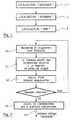
- la figure 1 présente un organigramme simplifié d'un mode de réalisationparticulier du procédé de localisation selon l'invention ;
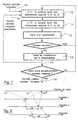
- la figure 2 présente un organigramme simplifié d'un mode de réalisationparticulier de la phase de localisation "grossière" apparaissant sur l'organigrammede la figure 1 ;
- les figures 3 et 4 présentent chacune une vue, en perspective et de dessusrespectivement, d'un anneau de recherche d'un satellite à une élévation donnée,permettant d'expliciter l'une des étapes de l'organigramme de la figure 2 ;
- les figures 5 et 6 présentent chacune une vue, de côté et du satelliterespectivement, d'une surface isoélévation, permettant d'expliciter l'une desétapes de l'organigramme de la figure 2 ;
- la figure 7 présente un organigramme simplifié d'un mode de réalisationparticulier de la phase de localisation "moyenne" apparaissant sur l'organigrammede la figure 1;
- la figure 8 présente un schéma illustrant de façon temporelle certaines étapes del'organigramme de la figure 7 ;
- la figure 9 présente un organigramme simplifié d'un premier mode de réalisationparticulier de la phase de localisation "fine" apparaissant sur l'organigramme de lafigure 1 ;
- la figure 10 présente un schéma illustrant de façon temporelle certaines étapes del'organigramme de la figure 9 ; et
- la figure 11 présente un organigramme simplifié d'un second mode de réalisationparticulier de la phase de localisation "fine" apparaissant sur l'organigramme de la figure 1.
- FIG. 1 presents a simplified flowchart of a particular embodiment of the location method according to the invention;
- FIG. 2 presents a simplified flowchart of a particular embodiment of the "coarse" location phase appearing on the flowchart of FIG. 1;
- FIGS. 3 and 4 each present a view, in perspective and from above respectively, of a search ring for a satellite at a given elevation, making it possible to explain one of the steps of the flow diagram of FIG. 2;
- FIGS. 5 and 6 each present a side view, of the satellite respectively, of an isoelevation surface, making it possible to explain one of the steps of the flow diagram of FIG. 2;
- FIG. 7 presents a simplified flowchart of a particular embodiment of the "average" location phase appearing on the flowchart of FIG. 1;
- FIG. 8 presents a diagram illustrating in time certain stages of the flow diagram of FIG. 7;
- FIG. 9 presents a simplified flowchart of a first particular embodiment of the "fine" localization phase appearing on the flowchart of FIG. 1;
- FIG. 10 presents a diagram illustrating in time certain stages of the flow chart of FIG. 9; and
- FIG. 11 presents a simplified flowchart of a second particular embodiment of the "fine" localization phase appearing on the flowchart of FIG. 1.
L'invention concerne donc un procédé de localisation d'un terminal fixe d'unsystème de télécommunications par satellites.The invention therefore relates to a method for locating a fixed terminal of asatellite communications system.
De façon classique, et comme déjà expliqué plus en détail ci-dessus, un telsystème de télécommunications par satellites comprend une constellation de satellites, unepluralité de stations de base et une pluralité de terminaux fixe.Conventionally, and as already explained in more detail above, such asatellite communications system includes a constellation of satellites, aplurality of base stations and a plurality of fixed terminals.
Dans le mode de réalisation particulier de la figure 1, le procédé de localisationselon l'invention comprend :
- une phase de localisation "grossière" 1, par exemple à ± 100 km ;
- une phase de localisation "moyenne" 2, par exemple à ± 350 m ; et
- une phase de localisation "fine" 3, par exemple à ± 60 m.
- a "coarse"
location phase 1, for example within ± 100 km; - an "average"
localization phase 2, for example at ± 350 m; and - a "fine"
localization phase 3, for example at ± 60 m.
A titre d'exemple, on suppose que chaque terminal comprend deux antennesdirectives permettant la réception simultanée d'informations émises par deux satellitesdistincts. Il est clair cependant que chaque terminal peut comprendre des moyens d'écoutesimultanée de plus de deux satellites.For example, it is assumed that each terminal includes two antennasguidelines for the simultaneous reception of information from two satellitesseparate. It is clear, however, that each terminal can include listening meansmore than two satellites simultaneously.
On présente maintenant, en relation avec les figures 2 à 6, un mode de réalisationparticulier de la phase de localisation "grossière" 1.We now present, in relation to FIGS. 2 to 6, an embodimentparticular of the "coarse"
Comme présenté sur l'organigramme simplifié de la figure 2, dans ce mode deréalisation particulier, la phase de localisation "grossière" 1 comprend les étapessuivantes:
- le terminal recherche et acquiert (20) un satellite, pour une élévation αprédéterminée, en faisant varier son azimuth ;
- le terminal reçoit (21) du satellite acquis une information relative à la position dece satellite acquis ;
- le terminal calcule (22), à partir de l'information relative à la position du satelliteacquis, une surface isoélévation, projetée sur un modèle de terre prédéterminé etsur laquelle se trouve le terminal;
- le terminal réitère les étapes précitées 20 à 22, de façon à effectuer N itérations autotal, avec N ≥ 3. Le terminal calcule donc N surfaces isoélévation sur lesquelles ilse trouve. Les N satellites, acquis lors des N itérations des étapes précitées 20 à 22, possèdent des azimuths , vus par le terminal, distants par exemple d'aumoins 30°. D'une façon générale, sur les N satellites, acquis lors des itérationssuccessives, au moins un possède un azimuth , vus par le terminal, distant d'aumoins 10° des azimuth des deux autres satellites ;
- le terminal détermine (23) une position estimée "grossière", en calculantl'intersection des N surfaces isoélévation.
- the terminal searches for and acquires (20) a satellite, for a predetermined elevation α, by varying its azimuth ;
- the terminal receives (21) from the acquired satellite information relating to the position of this acquired satellite;
- the terminal calculates (22), from the information relating to the position of the acquired satellite, an isoelevation surface, projected onto a predetermined earth model and on which the terminal is located;
- the terminal repeats the
aforementioned steps 20 to 22, so as to perform N iterations in total, with N ≥ 3. The terminal therefore calculates N isoelevation surfaces on which it is located. The N satellites, acquired during the N iterations of theaforementioned steps 20 to 22, have azimuths , seen by the terminal, for example at least 30 ° apart. In general, on the N satellites, acquired during successive iterations, at least one has an azimuth , seen by the terminal, distant at least 10 ° from the azimuth of the other two satellites; - the terminal determines (23) an estimated "coarse" position, by calculating the intersection of the N isoelevation surfaces.
Au cours de l'étape référencée 20, le terminal recherche un satellite dans unanneau où le satellite peut potentiellement se trouver, sachant que le satellite se trouve àune distance prédéterminée de la terre (par exemple 1500 km). Les figures 3 et 4présentent chacune une vue, en perspective et de dessus respectivement, d'un tel anneau30 de recherche par le terminal T d'un satellite S à une élévation a donnée. Au cours decette étape 20 de recherche et d'acquisition, les deux antennes directives du terminaltournent à une même élévation, chacune couvrant environ 180° autour de l'angled'azimuth .During the step referenced 20, the terminal searches for a satellite in aring where the satellite can potentially be located, knowing that the satellite is ata predetermined distance from the earth (for example 1500 km). Figures 3 and 4each have a view, in perspective and from above respectively, of such a
Les figures 5 et 6 présentent chacune une vue, de côté et de dessus (du satellite S)respectivement, d'une surface isoélévation calculée par le terminal T lors de l'étaperéférencée 22. En considérant une projection sur un modèle de terre sphérique parfait, etdu fait de l'incertitude δα sur l'élévation α, la surface isoélévation est une couronne 50. Ilest clair que d'autres modèles de terre, plus complexes, peuvent également être envisagéssans sortir du cadre de la présente invention.Figures 5 and 6 each show a side and top view (of satellite S)respectively, of an isoelevation surface calculated by the terminal T during the stepreferenced 22. By considering a projection on a perfect spherical earth model, anddue to the uncertainty δα on the elevation α, the isoelevation surface is a
A l'issue de cette phase de localisation "grossière" 1, le terminal dispose d'uneposition estimée "grossière" 24, par exemple à 200 km (c'est-à-dire à ± 100 km). Enoutre, le terminal peut effectuer une correction du biais en azimuth, par exemple à environ± 2°, grâce à la localisation "grossière" du terminal et des N satellites acquissuccessivement, ainsi qu'une correction du temps à quelques millisecondes, ce qui permetde garder une référence temporelle inférieure à 1 seconde pendant toute les phasessuivantes de localisation "moyenne" et "fine".At the end of this "rough"
On présente maintenant, en relation avec les figures 7 et 8, un mode de réalisationparticulier de la phase de localisation "moyenne" 2.We now present, in relation to FIGS. 7 and 8, an embodimentparticular of the "average"
Comme présenté sur l'organigramme simplifié de la figure 7, dans ce mode de réalisation particulier, la phase de localisation "moyenne" 1 comprend les étapessuivantes:
- à un premier instant t1', le terminal reçoit (70) d'un premier satellite actif("
satellite 1") de premières informations relatives d'une part à l'instant t1 deretransmission des premières informations par le premier satellite actif et d'autrepart à la position pi du premier satellite actif à l'instant t1 ; - à un second instant t2', égal à ou proche du premier instant t1', le terminal reçoit(71) d'un second satellite actif ("
satellite 2") de secondes informations relativesd'une part à l'instant t2 de retransmission des secondes informations par le secondsatellite actif et d'autre part à la position p2 du second satellite actif à l'instant t2 ; - le terminal calcule (72) un premier hyperboloïde H1,2 sur lequel se trouve leterminal (cf explication détaillée ci-dessous) ;
- le terminal réitère les étapes précitées 70 à 72, de façon à effectuer N itérations autotal, avec N ≥ 3. Le terminal calcule donc N hyperboloïdes sur lesquels il setrouve ;
- connaissant la position estimée "grossière" 24, le terminal détermine (73) uneposition estimée "moyenne" 74, en calculant l'intersection des N hyperboloïdes.
- at a first instant t1 ', the terminal receives (70) from a first active satellite ("
satellite 1") first information relating on the one hand to the instant t1 of retransmission of the first information by the first active satellite and d on the other hand to the position pi of the first active satellite at time t1; - at a second instant t2 ', equal to or close to the first instant t1', the terminal receives (71) from a second active satellite ("
satellite 2") second information relating on the one hand to the instant t2 of retransmission second information by the second active satellite and on the other hand at the position p2 of the second active satellite at time t2; - the terminal calculates (72) a first hyperboloid H1,2 on which the terminal is located (see detailed explanation below);
- the terminal repeats the
aforementioned steps 70 to 72, so as to perform N iterations in total, with N ≥ 3. The terminal therefore calculates N hyperboloids on which it is located; - knowing the estimated "coarse"
position 24, the terminal determines (73) an estimated "average"position 74, by calculating the intersection of the N hyperboloids.
Eventuellement, en utilisant la position estimée "moyenne" (précédente) 74 à laplace de la position estimée "grossière" 24, le terminal peut réitérer M fois les N itérationsdes étapes précitées 70 à 72 ainsi que l'étape précitée 73, de façon à obtenir M fois unenouvelle position estimée "moyenne" 74'.Optionally, using the estimated "average" position (previous) 74 at theinstead of the estimated "rough"
Ces M nouvelles positions estimées "moyennes" peuvent être calculéessuccessivement, soit chacune à partir de la position estimée "moyenne" de l'itération quiprécède, soit toutes à partir d'une même position estimée ("grossière" ou "moyenne"précédente).These M new estimated "average" positions can be calculatedsuccessively, either each from the estimated "average" position of the iteration whichprecedes, either all from the same estimated position ("coarse" or "average"previous).
Dans le second cas, on peut alors prévoir d'optimiser l'étape 73 de déterminationde la position estimée "moyenne" 74. Pour cela, on recherche le point P, parmi unensemble prédéterminé de points, qui minimise l'erreur que présente la position estimée"moyenne" du terminal, lorsque cette erreur est cumulée sur les M positions estimées"moyennes" toutes calculées à partir d'une même position estimée "grossière" ou "moyenne" précédente. L'ensemble prédéterminé de points est par exemple un disquedont le centre est la position estimée "grossière" (pour le premier calcul d'une positionestimée "moyenne") ou la position estimée "moyenne" précédente (pour chaque calculd'une nouvelle position estimée "moyenne"), et le rayon est l'incertitude présentée par laposition estimée ("grossière" ou "moyenne" précédente) à laquelle est égal le centre dudisque.In the second case, one can then plan to optimize the
Chaque hyperboloïde Hi,j calculé par le terminal lors de l'étape référencée 72 esttel que : Hi,j = dj - di = (tj' - tj).c - (ti' - ti).c, où :
- di est la distance entre le terminal et la position pi du ième satellite actif à l'instant ti,
- dj est la distance entre le terminal et la position pj du jème satellite actif à l'instant tj,
- ti et tj sont les ième et jème instants de retransmission par les ième et jème satellitesrespectivement,
- ti' et tj' sont les ième et jème instants de réception par le terminal,
- c est la vitesse de la lumière.
- di is the distance between the terminal and the position pi of the ith active satellite at time ti,
- dj is the distance between the terminal and the position pj of the jth active satellite at time tj,
- ti and tj are the i th and j th instants of retransmission by the i th and j th satellites respectively,
- ti 'and tj' are the ith and jth moments of reception by the terminal,
- c is the speed of light.
La relation définissant chaque hyperboloïde Hi,j peut également écrire :
Le terminal peut calculer Δt' et Δt puisqu'il reçoit ti et tj. Par ailleurs, il mesure lui-mêmeti' et tj'. Par conséquent, connaissant les positions pi et pj des ième et jèmesatellites aux instants ti et tj respectivement, le terminal peut calculer l'hyperboloïde Hi,j.The terminal can calculate Δt 'and Δt since it receives ti and tj. Furthermore, it measures ti 'and tj' itself. Consequently, knowing the positions pi and pj of the ith and jth satellites at times ti and tj respectively, the terminal can calculate the hyperboloid Hi, j .
Pour le calcul d'un hyperboloïde Hi,j, on utilise soit deux satellites actifssimultanément actifs à un instant quelconque, soit deux satellites actifs (sortant et entrantrespectivement) simultanément actifs uniquement lors d'un saut inter-satellites ("hand-off').For the calculation of a hyperboloid Hi, j , one uses either two active satellites simultaneously active at any time, or two active satellites (outgoing and entering respectively) simultaneously active only during an inter-satellite jump ("hand- off ').
Chacune des deux antennes directives du terminal est pointée sur un satellitedistinct. Comme déjà précisé ci-dessus, il est clair que si le terminal peut écoutersimultanément plus de deux satellites actifs, alors plusieurs hyperboloïdes peuvent êtrecalculés à partir des différentes informations reçues. Chaque couple de satellites permet decalculer un hyperboloïde.Each of the terminal's two directional antennas is pointed at a satelliteseparate. As already stated above, it is clear that if the terminal can listensimultaneously more than two active satellites, then several hyperboloids can becalculated from the different information received. Each pair of satellites allowscalculate a hyperboloid.
La figure 8 permet de visualiser les instants t1, t2, t1' et t2', avec les élémentsrespectifs concernés (à savoir le premier satellite pour t1, le second satellite pour t2, et le terminal pour t1' et t2'), ainsi que les intervalles de temps Δt et Δt'. Cette figure 8 illustreégalement le fait que la station de base émet, à des instants ts1 et ts2, les premières etsecondes informations que les premier et second satellites retransmettent aux instants t1 ett2. On notera que, dans l'exemple présenté, la station de base émet (aux instants ts1 et ts2)avec une précompensation temporelle, afin que les premières et secondes informationsretransmises (aux instants ts1 et ts2) par les premier et second satellites sont reçuessensiblement simultanément (à l'instant tGW0) par la station de base.FIG. 8 makes it possible to view the instants t1, t2, t1 'and t2', with the respective elements concerned (namely the first satellite for t1, the second satellite for t2, and the terminal for t1 'and t2'), thus than the time intervals Δt and Δt '. This FIG. 8 also illustrates the fact that the base station transmits, at instants ts1 and ts2 , the first and second information that the first and second satellites retransmit at instants t1 and t2. It will be noted that, in the example presented, the base station transmits (at times ts1 and ts2 ) with time precompensation, so that the first and second information retransmitted (at times ts1 and ts2 ) by the first and second satellites are received substantially simultaneously (at time tGW0 ) by the base station.
A l'issue de cette phase de localisation "moyenne" 1, le terminal dispose d'uneposition estimée "moyenne" 74 ou 74', par exemple à ± 350 m).At the end of this "average"
On présente maintenant, en relation avec les figures 9-10 et 11 respectivement, unpremier et un second modes de réalisation particuliers de la phase de localisation "fine" 3.We now present, in relation to Figures 9-10 and 11 respectively, afirst and second particular embodiments of the "fine"
Dans le premier mode de réalisation particulier, la phase de localisation "fine" 3comprend les étapes suivantes :
- la station de base (associée à la cellule dans laquelle se trouve le terminal) émet(90) vers le terminal, via un satellite actif, un message prédéterminé. Commeprésenté sur la figure 10, la station de base émet à l'instant tGW0 et le satelliteretransmet à l'instant ts0 ;
- le terminal reçoit, à l'instant tT0, le message prédéterminé et, connaissant d'unepart sa position estimée "moyenne" et d'autre part la position temps réel dusatellite actif, génère puis émet (91) vers la station de base, via le satellite actif, unmessage de réponse indiquant notamment l'intervalle de temps ΔtT entre l'instanttT0 de réception du message prédéterminé et l'instant d'émission tT du message deréponse. Comme présenté sur la figure 10, le satellite retransmet à l'instant ts lemessage de réponse émis par le terminal à l'instant tT ;
- la station de base reçoit, à l'instant "tGw mesuré", le message de réponse et, àpartir de ce dernier, calcule (92) une information relative à l'avance temporelleΔtTA que présente le message de réponse provenant du terminal. En fait, la stationde base calcule la différence AtTA entre l'instant de réception "tGW mesuré" etl'instant de réception "tGW attendu". On a : ΔtTA = 0 (c'est-à-dire une avancetemporelle nulle), seulement si la position estimée utilisée est parfaitement égale à la position réelle du terminal ;
- la station de base émet (93) vers le terminal, via le satellite actif, l'informationrelative à l'avance temporelle ΔtTA;
- à partir de l'information relative à l'avance temporelle ΔtTA et de la position. estimée "moyenne", le terminal calcule (94) sa position estimée "fine" 95 ;
- en utilisant la position estimée "fine" (précédente) 95 à la place de la positionestimée "moyenne" 74 ou 74', le terminal réitère M fois les étapes précitées 90 à94, de façon à obtenir M fois une nouvelle position estimée "fine" 95'. Chacunede ces M itération est par exemple effectuée avec un satellite distinct. On noteraque si c'est avec un même satellite, alors il est préférable que pour deux itérationssuccessives, le satellite possède des azimuths et/ou des élévations α, vus par leterminal, distants d'au moins 10°.
- the base station (associated with the cell in which the terminal is located) transmits (90) to the terminal, via an active satellite, a predetermined message. As shown in FIG. 10, the base station transmits at time tGW 0 and the satellite retransmits at time ts0 ;
- the terminal receives, at time tT0 , the predetermined message and, knowing on the one hand its estimated position "average" and on the other hand the real time position of the active satellite, generates then transmits (91) to the station basic, via the active satellite, a response message indicating in particular the time interval ΔtT between the instant tT0 of reception of the predetermined message and the instant of transmission tT of the response message. As shown in FIG. 10, the satellite retransmits at time ts the response message sent by the terminal at time tT ;
- the base station receives, at the instant "tGw measured", the response message and, from this latter, calculates (92) information relating to the time advance ΔtTA presented by the response message from the terminal. In fact, the base station calculates the difference AtTA between the time of reception "tGW measured" and the time of reception "tGW expected". We have: ΔtTA = 0 (that is to say a zero time advance), only if the estimated position used is perfectly equal to the real position of the terminal;
- the base station transmits (93) to the terminal, via the active satellite, the information relating to the time advance ΔtTA ;
- from the information relating to the time advance ΔtTA and the position. estimated "average", the terminal calculates (94) its estimated position "fine"95;
- using the “fine” (previous) estimated
position 95 in place of the “average” estimatedposition above steps 90 to 94 M times, so as to obtain M times a new estimated position " fine "95 '. Each of these M iteration is for example carried out with a separate satellite. It will be noted that if it is with the same satellite, then it is preferable that for two successive iterations, the satellite has azimuths and / or elevations α, seen by the terminal, distant at least 10 °.
Ces M nouvelles positions estimées "fines" peuvent être calculéessuccessivement, soit chacune à partir de la position estimée "fine" de l'itération quiprécède, soit toutes à partir d'une même position estimée ("moyenne" ou "fine"précédente).These M new positions estimated as "fine" can be calculatedsuccessively, either each from the estimated "fine" position of the iteration whichprecedes, either all from the same estimated position ("medium" or "fine"previous).
Dans le second cas, on peut alors prévoir d'optimiser l'étape 94 de déterminationde la position estimée "fine" 95. Pour cela, on recherche le point P; parmi un ensembleprédéterminé de points, qui minimise l'erreur que présente la position estimée "fine" duterminal, lorsque cette erreur est cumulée sur les M positions estimées "fines" toutescalculées à partir d'une même position estimée "moyenne" ou "fine" précédente.L'ensemble prédéterminé de points est par exemple un disque dont le centre est la positionestimée "moyenne" (pour le premier calcul d'une position estimée "fine") ou la positionestimée "fine" précédente (pour chaque calcul d'une nouvelle position estimée "fine"), etle rayon est l'incertitude présentée par la position estimée ("moyenne" ou "fine"précédente) à laquelle est égal le centre du disque.In the second case, it is then possible to plan to optimize the
Le second mode de réalisation de la phase de localisation "fine" 3, présenté surl'organigramme de la figure 11, se distingue du premier mode de réalisation en ce quec'est la station de base, et non pas le terminal, qui calcule la position estimée "fine" duterminal.The second embodiment of the "fine"
Dans le second mode de réalisation, la phase de localisation "fine" comprend donc, outreles étapes référencées 90 à 93 sur la figure 9 et déjà expliquées ci-dessus, les étapes préalable etfinale suivantes :
- le terminal émet (110) vers la station de base, via le satellite actif, une informationrelative à sa position estimée "fine" ;
- la station de base émet (112) vers le terminal, via le satellite actif, la position estimée"moyenne" du terminal.
- the terminal transmits (110) to the base station, via the active satellite, information relating to its estimated "fine"position;
- the base station transmits (112) to the terminal, via the active satellite, the estimated "average" position of the terminal.
Par ailleurs, l'étape référencée 94 sur la figure 9 est remplacée par l'étape 111 suivante :
- à partir de l'information relative à l'avance temporelle et de la position estimée"moyenne", la station de base calcule (111) la position estimée "fine" du terminal.
- from the information relating to the time advance and from the estimated "average" position, the base station calculates (111) the estimated "fine" position of the terminal.
Claims (15)
- A method of locating more accurately a fixed terminal of a satellitetelecommunication system comprising a constellation of satellites, a plurality ofgateway stations each associated with a separate geographical cell andconnected to a terrestrial telecommunication network, and a plurality of fixedterminals,
one or more satellites being active relative to a given gateway station only if theyare visible therefrom, each active satellite which receives information from thegateway station relative to which it is active transmits it to the fixed terminal orterminals in its coverage area, each active satellite that receives information froma fixed terminal in its coverage area transmitting the information to the gatewaystation relative to which it is active, the method including a first "coarse" locationphase able to provide a location area in which the coarse estimated position ofthe terminal is located,
characterized in that it comprises a second "intermediate" location phase (2)comprising the following steps:-i- at a first time t1', said terminal receives (70) from a first active satellite firstinformation relating to the time t1 of transmission of said first information by saidfirst active satellite and the position p1 of said first active satellite at said time t1;-ii- at a second time t2' the same as or close to said first time t1', said terminalreceives (71) from a second active satellite second information relating to thetime t2 of transmission of said second information by said second active satelliteand the position p2 of said second active satellite at said time t2;-iii- said terminal calculates (72) a first hyperboloid H1,2 on which saidterminal is located and such that:d1 is the distance between the terminal and said position p1 of the first activesatellite at time t1,d2 is the distance between the terminal and said position p2 of the secondactive satellite at time t2,t1 and t2 are said first and second times of transmission by said first andsecond satellites, respectively,+1' and t2' are said first and second times of reception by the terminal, andc is the speed of light;-iv- said terminal reiterates steps -i- through -iii- (70 through 72) at least twiceto calculate at least second and third hyperboloids on which said terminal islocated; and-v- said terminal determines (73) an "intermediate" estimated position bycalculating the intersection of said first and at least second and thirdhyperboloids taking into account the "coarse" estimated position of said terminal. - A method according to claim 1characterized in that, in said step -iv-, each newiteration of steps -i- through -iii- (70 through 72) is effected with a pair ofsatellites belonging to the group comprising:a pair of satellites separate from said first and second satellites; anda pair of satellites one of which is one of said first and second satellites andthe other of which is separate from said first and second satellites.
- A method according to claim 1 or claim 2characterized in that said"intermediate" location phase (2) further includes the following step:-vi- using the previous "intermediate" estimated position (74) instead of said"coarse" estimated position, said terminal reiterates at least once steps -i- through-v- to obtain a new "intermediate" estimated position (74').
- A method according to any one of claims 1 to 3characterized in that thegateway station relative to which said first and second satellites are activetransmits said first and second information with temporal precompensation suchthat after transmission by said first and second satellites said first and secondinformation is received substantially simultaneously by said gateway station.
- A method according to any one of claims 1 to 4characterized in that the paircomprising said first and second active satellites belongs to the groupcomprising:the pairs in which the two satellites are simultaneously active at any time; andthe pairs in which the two satellites, respectively outgoing and incoming, aresimultaneously active exclusively during hand-off between satellites, enabling agateway station to replace said outgoing active satellite, which is ceasing to bevisible, by said incoming active satellite, which is becoming visible.
- A method according to any one of claims 1 to 5characterized in that eachterminal has means for simultaneously receiving information transmitted by atleast two different satellites.
- A method according to claim 6characterized in that said means for simultaneously receiving information transmitted by at least two separatesatellites comprise at least two directional antennas each pointed at a separatesatellite.
- A method according to any one of claims 1 to 7characterized in that said"coarse" location phase (1) comprises the following steps:-a- said terminal searches for and acquires (20) a satellite for a predeterminedelevation angle α by varying its azimuth angle ;-b- said terminal receives (21) from said acquired satellite information relatingto the position of said acquired satellite;-c- said terminal calculates (22) from said information relating to the positionof the acquired satellite an iso-elevation surface projected onto a predeterminedEarth model and on which said terminal is located;-d- said terminal reiterates steps -a- through -c- (20 through 22) at least twiceso as to calculate at least two other iso-elevation surfaces on which said terminalis located; and-e- said terminal determines (23) a "coarse" estimated position by calculatingthe intersection of said at least three iso-elevation surfaces.
- A method according to claim 8characterized in that of said at least threesatellites acquired during successive iteration of steps -a- through -c- (20 through22) at least one has an azimuth angle as seen from said terminal separated byat least 10° from the azimuth angles of the other two satellites.
- A method according to claim 7 and claim 8 or claim 7 and claim 9
characterized in that, in said step -a- (20), said two directional antennas turnwith the same elevation angle, each covering approximately 180° about theazimuth angle . - A method according to any one of claims 1 to 10characterized in that said"intermediate" location phase (2) is followed by a "fine" location phase (3)comprising the following steps:-1- the gateway station associated with the cell in which said terminal islocated sends (90) said terminal a predetermined message via a satellite activerelative to said gateway station;-2- said terminal receives (91) said predetermined message and, knowing its"intermediate" estimated position and the real time position of the satellites ofsaid constellation, generates and then transmits to said gateway station via saidactive satellite a response message indicating in particular the time period between reception of said predetermined message and transmission of saidresponse message;-3- from said response message, said gateway station calculates (92)information relating to the timing advance of said terminal;-4- said gateway station transmits (93) to said terminal via said active satellitesaid information relating to the timing advance; and-5- from said information relating to the timing advance and from said"intermediate" estimated position said terminal calculates (94) its "fine" estimatedposition.
- A method according to claim 11characterized in that said "fine" locationphase (3) further includes the following preliminary and final steps:-0- said terminal transmits (110) information relating to the "intermediate"estimated position to said gateway station via said active satellite; and-6- said gateway station transmits (112) said "fine" estimated position of theterminal to said terminal via said active satellite;andin that said step -5- (94) is replaced by the following step:-5- from said information relating to the timing advance and said"intermediate" estimated position, said gateway station calculates (111) the "fine"estimated position of the terminal.
- Method according to claim 11 or claim 12characterized in that said "fine"location phase (3) further includes the following step:
-7- using the previous "fine" estimated position in place of said "intermediate"estimated position, said terminal reiterates at least once steps -1- through -5- (90through 92) or -0- through -6- (110, 90 through 93, 111 and 112) to obtain anew "fine" estimated position. - A method according to claim 13characterized in that, in step -7-, each newiteration of steps -1- through -5- or -0- through -6- is effected with the samesatellite but with azimuth angles and/or elevation angles α as seen from saidterminal separated by at least 10°.
- A method according to claim 13characterized in that each new iteration of steps
-1- through -5- or -0- through -6- in step 7 is effected with a different satellite.
Applications Claiming Priority (2)
| Application Number | Priority Date | Filing Date | Title |
|---|---|---|---|
| FR9710602AFR2767616B1 (en) | 1997-08-25 | 1997-08-25 | METHOD FOR LOCATING A FIXED TERMINAL THANKS TO A CONSTELLATION OF SATELLITES |
| FR9710602 | 1997-08-25 |
Publications (2)
| Publication Number | Publication Date |
|---|---|
| EP0899578A1 EP0899578A1 (en) | 1999-03-03 |
| EP0899578B1true EP0899578B1 (en) | 2001-10-04 |
Family
ID=9510459
Family Applications (1)
| Application Number | Title | Priority Date | Filing Date |
|---|---|---|---|
| EP98402097AExpired - LifetimeEP0899578B1 (en) | 1997-08-25 | 1998-08-24 | Method of localising the position of a fixed terminal employing a constellation of satellites |
Country Status (9)
| Country | Link |
|---|---|
| US (1) | US6195042B1 (en) |
| EP (1) | EP0899578B1 (en) |
| JP (1) | JPH11133132A (en) |
| CN (1) | CN1212375A (en) |
| CA (1) | CA2243620A1 (en) |
| DE (1) | DE69801879T2 (en) |
| ES (1) | ES2162403T3 (en) |
| FR (1) | FR2767616B1 (en) |
| ID (1) | ID20743A (en) |
Families Citing this family (7)
| Publication number | Priority date | Publication date | Assignee | Title |
|---|---|---|---|---|
| JP4726306B2 (en)* | 2001-01-31 | 2011-07-20 | パナソニック株式会社 | Wireless communication system, mobile terminal station and direction determination method |
| CN100336326C (en)* | 2002-10-11 | 2007-09-05 | 中兴通讯股份有限公司 | Method for positioning user device at soft changing state |
| US7203500B2 (en)* | 2003-08-01 | 2007-04-10 | Intel Corporation | Apparatus and associated methods for precision ranging measurements in a wireless communication environment |
| US20060238419A1 (en)* | 2005-04-25 | 2006-10-26 | Bucknor Brian E | Method and apparatus for aiding positioning of a satellite positioning system and receiver |
| CN104267420B (en)* | 2014-09-15 | 2017-04-05 | 中国电子科技集团公司第三十六研究所 | A kind of spaceborne 3-D positioning method to moving target, device and system |
| US10985835B2 (en)* | 2018-05-07 | 2021-04-20 | Atc Technologies, Llc | Devices, methods, and systems for uplink synchronization in time division multiple access (TDMA) satellite network |
| CN115606200B (en)* | 2020-11-30 | 2025-09-19 | 北京小米移动软件有限公司 | Position determining method, device and communication equipment |
Family Cites Families (2)
| Publication number | Priority date | Publication date | Assignee | Title |
|---|---|---|---|---|
| DE1591518B1 (en)* | 1967-07-21 | 1970-04-23 | Siemens Ag | Radio positioning process using satellites |
| US5126748A (en)* | 1989-12-05 | 1992-06-30 | Qualcomm Incorporated | Dual satellite navigation system and method |
- 1997
- 1997-08-25FRFR9710602Apatent/FR2767616B1/ennot_activeExpired - Fee Related
- 1998
- 1998-08-24CACA002243620Apatent/CA2243620A1/ennot_activeAbandoned
- 1998-08-24ESES98402097Tpatent/ES2162403T3/ennot_activeExpired - Lifetime
- 1998-08-24DEDE69801879Tpatent/DE69801879T2/ennot_activeExpired - Fee Related
- 1998-08-24CNCN98119868.6Apatent/CN1212375A/enactivePending
- 1998-08-24JPJP10236964Apatent/JPH11133132A/enactivePending
- 1998-08-24IDIDP981155Apatent/ID20743A/enunknown
- 1998-08-24EPEP98402097Apatent/EP0899578B1/ennot_activeExpired - Lifetime
- 1998-08-24USUS09/138,658patent/US6195042B1/ennot_activeExpired - Fee Related
Also Published As
| Publication number | Publication date |
|---|---|
| DE69801879D1 (en) | 2001-11-08 |
| EP0899578A1 (en) | 1999-03-03 |
| CN1212375A (en) | 1999-03-31 |
| CA2243620A1 (en) | 1999-02-25 |
| ES2162403T3 (en) | 2001-12-16 |
| FR2767616B1 (en) | 1999-09-24 |
| DE69801879T2 (en) | 2002-04-25 |
| US6195042B1 (en) | 2001-02-27 |
| ID20743A (en) | 1999-02-25 |
| JPH11133132A (en) | 1999-05-21 |
| FR2767616A1 (en) | 1999-02-26 |
Similar Documents
| Publication | Publication Date | Title |
|---|---|---|
| EP1804071B1 (en) | Method for optimising positioning data processing where there are several satellite positioning constellations | |
| CA2787939C (en) | Detection process for sia messages | |
| EP2444823B1 (en) | Method and system for geopositioning of a radio beacon in a warning system | |
| EP0327447B1 (en) | Radio navigation system | |
| US6567041B1 (en) | Network system and method for a remote reference receiver system | |
| US20020149515A1 (en) | Method for positioning, a positioning system, and an electronic device | |
| FR2740225A1 (en) | SATELLITE RADIO LOCATION APPARATUS AND METHOD AND SATELLITE PAYLOAD AS WELL AS EARTH STATION FOR CARRYING OUT SAID METHOD | |
| BR9909783B1 (en) | INCREASING SATELLITE POSITIONING SYSTEM WITH WIRELESS COMMUNICATION SIGNS | |
| FR2795525A1 (en) | METHOD AND APPARATUS FOR DETERMINING A GEOGRAPHICAL POSITION OF A MOBILE UNIT | |
| JP2004301838A (en) | Method and system for finding position of mobile terminal | |
| FR2753035A1 (en) | METHOD AND APPARATUS FOR POSITION SEARCHING IN A COMMUNICATION SYSTEM | |
| FR2782868A1 (en) | POSITION DETERMINATION SYSTEM AND METHOD USING A GEOSYNCHRONOUS LAND ORBIT SATELLITE | |
| EP3698173B1 (en) | Positioning system with gnss signal generation means and radiating cable | |
| FR2782226A1 (en) | METHOD FOR LOCATING A MOBILE TELEPHONE | |
| EP0899578B1 (en) | Method of localising the position of a fixed terminal employing a constellation of satellites | |
| EP1544636B1 (en) | Determination device by filtering of integrity data in a differential positioning system, for a mobile terminal | |
| EP1697757B1 (en) | Method of updating the clock bias between a bts station of a gsm network and the satellites of a gps system | |
| WO2001081943A1 (en) | Method and device for instantaneous determination of orientation, based on satellite positioning signals | |
| WO2007074266A1 (en) | Pre-location method and system for assisting satellite radio-navigation systems | |
| FR2878684A1 (en) | DEVICE FOR LOCATING MOBILE TERMINAL USING CORRECTED TIME MARKING SIGNALS FROM BASE STATIONS OF AN ASYNCHRONOUS MOBILE NETWORK | |
| EP1804399A1 (en) | Method for synchronising base stations of a terrestrial-cellular communication network | |
| EP1804070B1 (en) | Method for fast acquisition of satellite signals | |
| CA2411797C (en) | Method for secure determination of an object location, preferably a vehicle moving along a known course | |
| EP0702865B1 (en) | Selection of a primary satellite | |
| EP4158383A1 (en) | Cloud-offloaded gnss positioning method |
Legal Events
| Date | Code | Title | Description |
|---|---|---|---|
| PUAI | Public reference made under article 153(3) epc to a published international application that has entered the european phase | Free format text:ORIGINAL CODE: 0009012 | |
| AK | Designated contracting states | Kind code of ref document:A1 Designated state(s):DE ES FI GB IT | |
| AX | Request for extension of the european patent | Free format text:AL;LT;LV;MK;RO;SI | |
| RAP3 | Party data changed (applicant data changed or rights of an application transferred) | Owner name:ALCATEL | |
| 17P | Request for examination filed | Effective date:19990903 | |
| AKX | Designation fees paid | Free format text:DE ES FI GB IT | |
| 17Q | First examination report despatched | Effective date:20000322 | |
| GRAG | Despatch of communication of intention to grant | Free format text:ORIGINAL CODE: EPIDOS AGRA | |
| GRAG | Despatch of communication of intention to grant | Free format text:ORIGINAL CODE: EPIDOS AGRA | |
| GRAH | Despatch of communication of intention to grant a patent | Free format text:ORIGINAL CODE: EPIDOS IGRA | |
| GRAH | Despatch of communication of intention to grant a patent | Free format text:ORIGINAL CODE: EPIDOS IGRA | |
| GRAA | (expected) grant | Free format text:ORIGINAL CODE: 0009210 | |
| AK | Designated contracting states | Kind code of ref document:B1 Designated state(s):DE ES FI GB IT | |
| PG25 | Lapsed in a contracting state [announced via postgrant information from national office to epo] | Ref country code:FI Free format text:LAPSE BECAUSE OF FAILURE TO SUBMIT A TRANSLATION OF THE DESCRIPTION OR TO PAY THE FEE WITHIN THE PRESCRIBED TIME-LIMIT Effective date:20011004 | |
| GBT | Gb: translation of ep patent filed (gb section 77(6)(a)/1977) | Effective date:20011004 | |
| REF | Corresponds to: | Ref document number:69801879 Country of ref document:DE Date of ref document:20011108 | |
| REG | Reference to a national code | Ref country code:ES Ref legal event code:FG2A Ref document number:2162403 Country of ref document:ES Kind code of ref document:T3 | |
| REG | Reference to a national code | Ref country code:GB Ref legal event code:IF02 | |
| PLBE | No opposition filed within time limit | Free format text:ORIGINAL CODE: 0009261 | |
| STAA | Information on the status of an ep patent application or granted ep patent | Free format text:STATUS: NO OPPOSITION FILED WITHIN TIME LIMIT | |
| 26N | No opposition filed | ||
| PGFP | Annual fee paid to national office [announced via postgrant information from national office to epo] | Ref country code:GB Payment date:20030728 Year of fee payment:6 | |
| PGFP | Annual fee paid to national office [announced via postgrant information from national office to epo] | Ref country code:DE Payment date:20030805 Year of fee payment:6 | |
| PGFP | Annual fee paid to national office [announced via postgrant information from national office to epo] | Ref country code:ES Payment date:20030808 Year of fee payment:6 | |
| PG25 | Lapsed in a contracting state [announced via postgrant information from national office to epo] | Ref country code:GB Free format text:LAPSE BECAUSE OF NON-PAYMENT OF DUE FEES Effective date:20040824 | |
| PG25 | Lapsed in a contracting state [announced via postgrant information from national office to epo] | Ref country code:ES Free format text:LAPSE BECAUSE OF NON-PAYMENT OF DUE FEES Effective date:20040825 | |
| PG25 | Lapsed in a contracting state [announced via postgrant information from national office to epo] | Ref country code:DE Free format text:LAPSE BECAUSE OF NON-PAYMENT OF DUE FEES Effective date:20050301 | |
| GBPC | Gb: european patent ceased through non-payment of renewal fee | Effective date:20040824 | |
| PG25 | Lapsed in a contracting state [announced via postgrant information from national office to epo] | Ref country code:IT Free format text:LAPSE BECAUSE OF NON-PAYMENT OF DUE FEES;WARNING: LAPSES OF ITALIAN PATENTS WITH EFFECTIVE DATE BEFORE 2007 MAY HAVE OCCURRED AT ANY TIME BEFORE 2007. THE CORRECT EFFECTIVE DATE MAY BE DIFFERENT FROM THE ONE RECORDED. Effective date:20050824 | |
| REG | Reference to a national code | Ref country code:ES Ref legal event code:FD2A Effective date:20040825 |