EP0897700B1 - Stent delivery assembly for treating bifurcations - Google Patents
Stent delivery assembly for treating bifurcationsDownload PDFInfo
- Publication number
- EP0897700B1 EP0897700B1EP98301613AEP98301613AEP0897700B1EP 0897700 B1EP0897700 B1EP 0897700B1EP 98301613 AEP98301613 AEP 98301613AEP 98301613 AEP98301613 AEP 98301613AEP 0897700 B1EP0897700 B1EP 0897700B1
- Authority
- EP
- European Patent Office
- Prior art keywords
- vessel
- stent
- guide wire
- catheter
- main
- Prior art date
- Legal status (The legal status is an assumption and is not a legal conclusion. Google has not performed a legal analysis and makes no representation as to the accuracy of the status listed.)
- Expired - Lifetime
Links
Images


Classifications
- A—HUMAN NECESSITIES
- A61—MEDICAL OR VETERINARY SCIENCE; HYGIENE
- A61F—FILTERS IMPLANTABLE INTO BLOOD VESSELS; PROSTHESES; DEVICES PROVIDING PATENCY TO, OR PREVENTING COLLAPSING OF, TUBULAR STRUCTURES OF THE BODY, e.g. STENTS; ORTHOPAEDIC, NURSING OR CONTRACEPTIVE DEVICES; FOMENTATION; TREATMENT OR PROTECTION OF EYES OR EARS; BANDAGES, DRESSINGS OR ABSORBENT PADS; FIRST-AID KITS
- A61F2/00—Filters implantable into blood vessels; Prostheses, i.e. artificial substitutes or replacements for parts of the body; Appliances for connecting them with the body; Devices providing patency to, or preventing collapsing of, tubular structures of the body, e.g. stents
- A61F2/82—Devices providing patency to, or preventing collapsing of, tubular structures of the body, e.g. stents
- A61F2/856—Single tubular stent with a side portal passage
- A—HUMAN NECESSITIES
- A61—MEDICAL OR VETERINARY SCIENCE; HYGIENE
- A61F—FILTERS IMPLANTABLE INTO BLOOD VESSELS; PROSTHESES; DEVICES PROVIDING PATENCY TO, OR PREVENTING COLLAPSING OF, TUBULAR STRUCTURES OF THE BODY, e.g. STENTS; ORTHOPAEDIC, NURSING OR CONTRACEPTIVE DEVICES; FOMENTATION; TREATMENT OR PROTECTION OF EYES OR EARS; BANDAGES, DRESSINGS OR ABSORBENT PADS; FIRST-AID KITS
- A61F2/00—Filters implantable into blood vessels; Prostheses, i.e. artificial substitutes or replacements for parts of the body; Appliances for connecting them with the body; Devices providing patency to, or preventing collapsing of, tubular structures of the body, e.g. stents
- A61F2/82—Devices providing patency to, or preventing collapsing of, tubular structures of the body, e.g. stents
- A61F2/86—Stents in a form characterised by the wire-like elements; Stents in the form characterised by a net-like or mesh-like structure
- A61F2/90—Stents in a form characterised by the wire-like elements; Stents in the form characterised by a net-like or mesh-like structure characterised by a net-like or mesh-like structure
- A61F2/91—Stents in a form characterised by the wire-like elements; Stents in the form characterised by a net-like or mesh-like structure characterised by a net-like or mesh-like structure made from perforated sheets or tubes, e.g. perforated by laser cuts or etched holes
- A61F2/915—Stents in a form characterised by the wire-like elements; Stents in the form characterised by a net-like or mesh-like structure characterised by a net-like or mesh-like structure made from perforated sheets or tubes, e.g. perforated by laser cuts or etched holes with bands having a meander structure, adjacent bands being connected to each other
- A—HUMAN NECESSITIES
- A61—MEDICAL OR VETERINARY SCIENCE; HYGIENE
- A61F—FILTERS IMPLANTABLE INTO BLOOD VESSELS; PROSTHESES; DEVICES PROVIDING PATENCY TO, OR PREVENTING COLLAPSING OF, TUBULAR STRUCTURES OF THE BODY, e.g. STENTS; ORTHOPAEDIC, NURSING OR CONTRACEPTIVE DEVICES; FOMENTATION; TREATMENT OR PROTECTION OF EYES OR EARS; BANDAGES, DRESSINGS OR ABSORBENT PADS; FIRST-AID KITS
- A61F2/00—Filters implantable into blood vessels; Prostheses, i.e. artificial substitutes or replacements for parts of the body; Appliances for connecting them with the body; Devices providing patency to, or preventing collapsing of, tubular structures of the body, e.g. stents
- A61F2/95—Instruments specially adapted for placement or removal of stents or stent-grafts
- A61F2/954—Instruments specially adapted for placement or removal of stents or stent-grafts for placing stents or stent-grafts in a bifurcation
- A—HUMAN NECESSITIES
- A61—MEDICAL OR VETERINARY SCIENCE; HYGIENE
- A61F—FILTERS IMPLANTABLE INTO BLOOD VESSELS; PROSTHESES; DEVICES PROVIDING PATENCY TO, OR PREVENTING COLLAPSING OF, TUBULAR STRUCTURES OF THE BODY, e.g. STENTS; ORTHOPAEDIC, NURSING OR CONTRACEPTIVE DEVICES; FOMENTATION; TREATMENT OR PROTECTION OF EYES OR EARS; BANDAGES, DRESSINGS OR ABSORBENT PADS; FIRST-AID KITS
- A61F2/00—Filters implantable into blood vessels; Prostheses, i.e. artificial substitutes or replacements for parts of the body; Appliances for connecting them with the body; Devices providing patency to, or preventing collapsing of, tubular structures of the body, e.g. stents
- A61F2/95—Instruments specially adapted for placement or removal of stents or stent-grafts
- A61F2/958—Inflatable balloons for placing stents or stent-grafts
- A—HUMAN NECESSITIES
- A61—MEDICAL OR VETERINARY SCIENCE; HYGIENE
- A61M—DEVICES FOR INTRODUCING MEDIA INTO, OR ONTO, THE BODY; DEVICES FOR TRANSDUCING BODY MEDIA OR FOR TAKING MEDIA FROM THE BODY; DEVICES FOR PRODUCING OR ENDING SLEEP OR STUPOR
- A61M25/00—Catheters; Hollow probes
- A61M25/10—Balloon catheters
- A—HUMAN NECESSITIES
- A61—MEDICAL OR VETERINARY SCIENCE; HYGIENE
- A61F—FILTERS IMPLANTABLE INTO BLOOD VESSELS; PROSTHESES; DEVICES PROVIDING PATENCY TO, OR PREVENTING COLLAPSING OF, TUBULAR STRUCTURES OF THE BODY, e.g. STENTS; ORTHOPAEDIC, NURSING OR CONTRACEPTIVE DEVICES; FOMENTATION; TREATMENT OR PROTECTION OF EYES OR EARS; BANDAGES, DRESSINGS OR ABSORBENT PADS; FIRST-AID KITS
- A61F2/00—Filters implantable into blood vessels; Prostheses, i.e. artificial substitutes or replacements for parts of the body; Appliances for connecting them with the body; Devices providing patency to, or preventing collapsing of, tubular structures of the body, e.g. stents
- A61F2/02—Prostheses implantable into the body
- A61F2/04—Hollow or tubular parts of organs, e.g. bladders, tracheae, bronchi or bile ducts
- A61F2/06—Blood vessels
- A61F2002/065—Y-shaped blood vessels
- A61F2002/067—Y-shaped blood vessels modular
- A—HUMAN NECESSITIES
- A61—MEDICAL OR VETERINARY SCIENCE; HYGIENE
- A61F—FILTERS IMPLANTABLE INTO BLOOD VESSELS; PROSTHESES; DEVICES PROVIDING PATENCY TO, OR PREVENTING COLLAPSING OF, TUBULAR STRUCTURES OF THE BODY, e.g. STENTS; ORTHOPAEDIC, NURSING OR CONTRACEPTIVE DEVICES; FOMENTATION; TREATMENT OR PROTECTION OF EYES OR EARS; BANDAGES, DRESSINGS OR ABSORBENT PADS; FIRST-AID KITS
- A61F2/00—Filters implantable into blood vessels; Prostheses, i.e. artificial substitutes or replacements for parts of the body; Appliances for connecting them with the body; Devices providing patency to, or preventing collapsing of, tubular structures of the body, e.g. stents
- A61F2/82—Devices providing patency to, or preventing collapsing of, tubular structures of the body, e.g. stents
- A61F2002/821—Ostial stents
- A—HUMAN NECESSITIES
- A61—MEDICAL OR VETERINARY SCIENCE; HYGIENE
- A61F—FILTERS IMPLANTABLE INTO BLOOD VESSELS; PROSTHESES; DEVICES PROVIDING PATENCY TO, OR PREVENTING COLLAPSING OF, TUBULAR STRUCTURES OF THE BODY, e.g. STENTS; ORTHOPAEDIC, NURSING OR CONTRACEPTIVE DEVICES; FOMENTATION; TREATMENT OR PROTECTION OF EYES OR EARS; BANDAGES, DRESSINGS OR ABSORBENT PADS; FIRST-AID KITS
- A61F2/00—Filters implantable into blood vessels; Prostheses, i.e. artificial substitutes or replacements for parts of the body; Appliances for connecting them with the body; Devices providing patency to, or preventing collapsing of, tubular structures of the body, e.g. stents
- A61F2/82—Devices providing patency to, or preventing collapsing of, tubular structures of the body, e.g. stents
- A61F2/86—Stents in a form characterised by the wire-like elements; Stents in the form characterised by a net-like or mesh-like structure
- A61F2/90—Stents in a form characterised by the wire-like elements; Stents in the form characterised by a net-like or mesh-like structure characterised by a net-like or mesh-like structure
- A61F2/91—Stents in a form characterised by the wire-like elements; Stents in the form characterised by a net-like or mesh-like structure characterised by a net-like or mesh-like structure made from perforated sheets or tubes, e.g. perforated by laser cuts or etched holes
- A61F2/915—Stents in a form characterised by the wire-like elements; Stents in the form characterised by a net-like or mesh-like structure characterised by a net-like or mesh-like structure made from perforated sheets or tubes, e.g. perforated by laser cuts or etched holes with bands having a meander structure, adjacent bands being connected to each other
- A61F2002/91508—Stents in a form characterised by the wire-like elements; Stents in the form characterised by a net-like or mesh-like structure characterised by a net-like or mesh-like structure made from perforated sheets or tubes, e.g. perforated by laser cuts or etched holes with bands having a meander structure, adjacent bands being connected to each other the meander having a difference in amplitude along the band
- A—HUMAN NECESSITIES
- A61—MEDICAL OR VETERINARY SCIENCE; HYGIENE
- A61F—FILTERS IMPLANTABLE INTO BLOOD VESSELS; PROSTHESES; DEVICES PROVIDING PATENCY TO, OR PREVENTING COLLAPSING OF, TUBULAR STRUCTURES OF THE BODY, e.g. STENTS; ORTHOPAEDIC, NURSING OR CONTRACEPTIVE DEVICES; FOMENTATION; TREATMENT OR PROTECTION OF EYES OR EARS; BANDAGES, DRESSINGS OR ABSORBENT PADS; FIRST-AID KITS
- A61F2/00—Filters implantable into blood vessels; Prostheses, i.e. artificial substitutes or replacements for parts of the body; Appliances for connecting them with the body; Devices providing patency to, or preventing collapsing of, tubular structures of the body, e.g. stents
- A61F2/82—Devices providing patency to, or preventing collapsing of, tubular structures of the body, e.g. stents
- A61F2/86—Stents in a form characterised by the wire-like elements; Stents in the form characterised by a net-like or mesh-like structure
- A61F2/90—Stents in a form characterised by the wire-like elements; Stents in the form characterised by a net-like or mesh-like structure characterised by a net-like or mesh-like structure
- A61F2/91—Stents in a form characterised by the wire-like elements; Stents in the form characterised by a net-like or mesh-like structure characterised by a net-like or mesh-like structure made from perforated sheets or tubes, e.g. perforated by laser cuts or etched holes
- A61F2/915—Stents in a form characterised by the wire-like elements; Stents in the form characterised by a net-like or mesh-like structure characterised by a net-like or mesh-like structure made from perforated sheets or tubes, e.g. perforated by laser cuts or etched holes with bands having a meander structure, adjacent bands being connected to each other
- A61F2002/91516—Stents in a form characterised by the wire-like elements; Stents in the form characterised by a net-like or mesh-like structure characterised by a net-like or mesh-like structure made from perforated sheets or tubes, e.g. perforated by laser cuts or etched holes with bands having a meander structure, adjacent bands being connected to each other the meander having a change in frequency along the band
- A—HUMAN NECESSITIES
- A61—MEDICAL OR VETERINARY SCIENCE; HYGIENE
- A61F—FILTERS IMPLANTABLE INTO BLOOD VESSELS; PROSTHESES; DEVICES PROVIDING PATENCY TO, OR PREVENTING COLLAPSING OF, TUBULAR STRUCTURES OF THE BODY, e.g. STENTS; ORTHOPAEDIC, NURSING OR CONTRACEPTIVE DEVICES; FOMENTATION; TREATMENT OR PROTECTION OF EYES OR EARS; BANDAGES, DRESSINGS OR ABSORBENT PADS; FIRST-AID KITS
- A61F2/00—Filters implantable into blood vessels; Prostheses, i.e. artificial substitutes or replacements for parts of the body; Appliances for connecting them with the body; Devices providing patency to, or preventing collapsing of, tubular structures of the body, e.g. stents
- A61F2/82—Devices providing patency to, or preventing collapsing of, tubular structures of the body, e.g. stents
- A61F2/86—Stents in a form characterised by the wire-like elements; Stents in the form characterised by a net-like or mesh-like structure
- A61F2/90—Stents in a form characterised by the wire-like elements; Stents in the form characterised by a net-like or mesh-like structure characterised by a net-like or mesh-like structure
- A61F2/91—Stents in a form characterised by the wire-like elements; Stents in the form characterised by a net-like or mesh-like structure characterised by a net-like or mesh-like structure made from perforated sheets or tubes, e.g. perforated by laser cuts or etched holes
- A61F2/915—Stents in a form characterised by the wire-like elements; Stents in the form characterised by a net-like or mesh-like structure characterised by a net-like or mesh-like structure made from perforated sheets or tubes, e.g. perforated by laser cuts or etched holes with bands having a meander structure, adjacent bands being connected to each other
- A61F2002/91533—Stents in a form characterised by the wire-like elements; Stents in the form characterised by a net-like or mesh-like structure characterised by a net-like or mesh-like structure made from perforated sheets or tubes, e.g. perforated by laser cuts or etched holes with bands having a meander structure, adjacent bands being connected to each other characterised by the phase between adjacent bands
- A—HUMAN NECESSITIES
- A61—MEDICAL OR VETERINARY SCIENCE; HYGIENE
- A61F—FILTERS IMPLANTABLE INTO BLOOD VESSELS; PROSTHESES; DEVICES PROVIDING PATENCY TO, OR PREVENTING COLLAPSING OF, TUBULAR STRUCTURES OF THE BODY, e.g. STENTS; ORTHOPAEDIC, NURSING OR CONTRACEPTIVE DEVICES; FOMENTATION; TREATMENT OR PROTECTION OF EYES OR EARS; BANDAGES, DRESSINGS OR ABSORBENT PADS; FIRST-AID KITS
- A61F2/00—Filters implantable into blood vessels; Prostheses, i.e. artificial substitutes or replacements for parts of the body; Appliances for connecting them with the body; Devices providing patency to, or preventing collapsing of, tubular structures of the body, e.g. stents
- A61F2/82—Devices providing patency to, or preventing collapsing of, tubular structures of the body, e.g. stents
- A61F2/86—Stents in a form characterised by the wire-like elements; Stents in the form characterised by a net-like or mesh-like structure
- A61F2/90—Stents in a form characterised by the wire-like elements; Stents in the form characterised by a net-like or mesh-like structure characterised by a net-like or mesh-like structure
- A61F2/91—Stents in a form characterised by the wire-like elements; Stents in the form characterised by a net-like or mesh-like structure characterised by a net-like or mesh-like structure made from perforated sheets or tubes, e.g. perforated by laser cuts or etched holes
- A61F2/915—Stents in a form characterised by the wire-like elements; Stents in the form characterised by a net-like or mesh-like structure characterised by a net-like or mesh-like structure made from perforated sheets or tubes, e.g. perforated by laser cuts or etched holes with bands having a meander structure, adjacent bands being connected to each other
- A61F2002/9155—Adjacent bands being connected to each other
- A61F2002/91575—Adjacent bands being connected to each other connected peak to trough
- A—HUMAN NECESSITIES
- A61—MEDICAL OR VETERINARY SCIENCE; HYGIENE
- A61F—FILTERS IMPLANTABLE INTO BLOOD VESSELS; PROSTHESES; DEVICES PROVIDING PATENCY TO, OR PREVENTING COLLAPSING OF, TUBULAR STRUCTURES OF THE BODY, e.g. STENTS; ORTHOPAEDIC, NURSING OR CONTRACEPTIVE DEVICES; FOMENTATION; TREATMENT OR PROTECTION OF EYES OR EARS; BANDAGES, DRESSINGS OR ABSORBENT PADS; FIRST-AID KITS
- A61F2250/00—Special features of prostheses classified in groups A61F2/00 - A61F2/26 or A61F2/82 or A61F9/00 or A61F11/00 or subgroups thereof
- A61F2250/0014—Special features of prostheses classified in groups A61F2/00 - A61F2/26 or A61F2/82 or A61F9/00 or A61F11/00 or subgroups thereof having different values of a given property or geometrical feature, e.g. mechanical property or material property, at different locations within the same prosthesis
- A—HUMAN NECESSITIES
- A61—MEDICAL OR VETERINARY SCIENCE; HYGIENE
- A61F—FILTERS IMPLANTABLE INTO BLOOD VESSELS; PROSTHESES; DEVICES PROVIDING PATENCY TO, OR PREVENTING COLLAPSING OF, TUBULAR STRUCTURES OF THE BODY, e.g. STENTS; ORTHOPAEDIC, NURSING OR CONTRACEPTIVE DEVICES; FOMENTATION; TREATMENT OR PROTECTION OF EYES OR EARS; BANDAGES, DRESSINGS OR ABSORBENT PADS; FIRST-AID KITS
- A61F2250/00—Special features of prostheses classified in groups A61F2/00 - A61F2/26 or A61F2/82 or A61F9/00 or A61F11/00 or subgroups thereof
- A61F2250/0058—Additional features; Implant or prostheses properties not otherwise provided for
- A61F2250/006—Additional features; Implant or prostheses properties not otherwise provided for modular
- A—HUMAN NECESSITIES
- A61—MEDICAL OR VETERINARY SCIENCE; HYGIENE
- A61M—DEVICES FOR INTRODUCING MEDIA INTO, OR ONTO, THE BODY; DEVICES FOR TRANSDUCING BODY MEDIA OR FOR TAKING MEDIA FROM THE BODY; DEVICES FOR PRODUCING OR ENDING SLEEP OR STUPOR
- A61M25/00—Catheters; Hollow probes
- A61M25/10—Balloon catheters
- A61M2025/1043—Balloon catheters with special features or adapted for special applications
- A61M2025/1045—Balloon catheters with special features or adapted for special applications for treating bifurcations, e.g. balloons in y-configuration, separate balloons or special features of the catheter for treating bifurcations
Definitions
- the inventionrelates to stent deployment assemblies for use at a bifurcation and, more particularly, to a catheter assembly for implanting one or more stents for repairing bifurcations, the aorto-ostium, and bifurcated blood vessels that are diseased, as specified in the preamble of Claim 1.
- a stent delivery assemblyis known e.g. from WO-A-96/34580.
- Stentsconventionally repair blood vessels that are diseased and generally are hollow and cylindrical in shape, having terminal ends that are generally perpendicular to its longitudinal axis.
- the conventional stentis positioned at the diseased area of a vessel and, after placement, the stent provides an unobstructed pathway for blood flow.
- the stentwithout compromising blood flow, must overlay the entire circumference of the ostium to a diseased portion and extend to a point within and beyond the diseased portion.
- the stentfails to completely repair the bifurcated vessel.
- the stentoverlays the entire circumference of the ostium to the diseased portion, yet extends into the junction comprising the bifurcation, the diseased area is repaired, but blood flow may be compromised in other portions of the bifurcation.
- Unapposed stent elementsmay promote lumen compromise during neointimalization and healing, producing restenosis and requiring further procedures. Moreover, by extending into the junction comprising the bifurcation, the stent may block access to portions of the bifurcated vessel that require performance of further interventional procedures. Similar problems are encountered when a vessel is diseased at the point of its angled origin from the aorta, as in the ostium of a right coronary artery or a vein graft. In this circumstance, a stent overlying the entire circumference of the ostium extends back into the aorta, creating problems, including that of complicating catheter access to the vessel in any additional interventional procedures.
- Conventional stentsare designed to repair areas of blood vessels that are removed from the sites of bifurcations and, because a conventional stent generally terminates at right angles to its longitudinal axis, the use of conventional stents in the region of a vessel bifurcation may result in blocking the flow of blood through a side branch or may fail to repair the bifurcation to the full extent necessary.
- a conventional stentmight be placed so that a portion of the stent extends into the pathway of blood flow to a side branch of the bifurcation or so that it extends so far as to completely cover the path of blood flow in a side branch.
- a conventional stentalternatively might be placed proximal to, but not entirely overlaying, the circumference of the ostium to the diseased portion.
- Such positioning of a conventional stentresults in a bifurcation that is not completely repaired.
- extremely precise positioning of the conventional stentis required.
- This extremely precise positioning of the conventional stentmay result in the right-angled terminal ends of the conventional stent overlying the entire circumference of the ostium to the diseased portion without extending into a side branch, thereby completely repairing the right-angled bifurcation.
- a stentthat consistently overlays the entire circumference of the ostium to a diseased portion, yet does not extend into the junction comprising the bifurcation, may be employed.
- Such a stenthas the advantage of completely repairing the vessel at the bifurcation without obstructing blood flow in other portions of the bifurcation.
- such a stentallows access to all portions of the bifurcated vessel, should further interventional treatment be necessary.
- a conventional stentis implanted in the main vessel so that a portion of the stent is across the side branch, so that stenting of the side branch must occur through the main-vessel stent struts.
- the main-vessel stent strutsmust be spread apart to form an opening to the side-branch vessel and then a catheter with a stent is delivered through the opening.
- the "cell" or the portion of the main-vessel stent struts to be spread apartmust be randomly and blindly selected by re-crossing the deployed stent with a wire.
- a drawback with this approachis that there is no way to determine or guarantee that the main-vessel stent struts are oriented properly with respect to the side branch or that the appropriate cell has been selected by the wire for dilatation.
- the aperture createdoften does not provide a clear opening and creates significant distortion in the surrounding stent struts. Thus, there is no way to tell if the main-vessel stent struts have been properly oriented and spread apart to provide a clear opening for stenting the side-branch vessel.
- the side-branch vesselis first stented so that the stent protrudes into the main vessel.
- a dilatationis then performed in the main vessel to open and stretch the stent struts extending across the lumen from the side-branch vessel.
- the main-vessel stentis implanted so that its proximal end overlaps with the side-branch vessel.
- the deployed stentmust be re-crossed with a wire blindly, and then arbitrarily selecting a particular stent cell.
- the stretching of the stent strutstherefore is random, leaving the possibility of restricted access, incomplete lumen dilatation, and major stent distortion.
- a "T" stent procedureincludes implanting a stent in the side-branch ostium of the bifurcation followed by stenting the main vessel across the side-branch ostium.
- a stentis implanted in the main vessel with a side-branch stent partially extending into the main vessel creating a double-barreled lumen of the two stents in the main vessel distal to the bifurcation.
- Another prior art approachincludes a so-called "trouser legs and seat” approach, which includes implanting three stents, one stent in the side-branch vessel, a second stent in a distal portion of the main vessel, and a third stent, or a proximal stent, in the main vessel just proximal to the bifurcation.
- All of the foregoing stent deployment assembliessuffer from the same problems and limitations.
- An uncovered flap or fold in the intima or plaquewill invite a "snowplow" effect, representing a substantial risk for sub-acute thrombosis, and the increased risk of restenosis.
- portions of the stentare left un-apposed within the lumen, the risk of sub-acute thrombosis or restenosis again is increased.
- the prior art stents and delivery assemblies for treating bifurcationsare difficult to use, making successful placement of the stents nearly impossible.
- the side-branch vesselcan be "jailed" or covered so that there is impaired access to the stented area for subsequent intervention.
- WO 96/34580(which corresponds to the preamble of Claim 1) an endoprosthesis for the treatment of blood-vessel bifurcation stenosis that is characterised by the fact that it comprises three tubular sections and two connectors. These sections comprise a proximal section and a first distal section aligned at least approximately with the proximal section and intended for insertion into a first blood vessel branching off on the bifurcation. The first distal section is linked to the proximal section by a first lateral connector. A second distal section is located at the side of the first distal section and intended for insertion into a second vessel branching off from the bifurcation. The two distal sections have their proximal ends linked by a second connector. There is also described a double-balloon dilation system.
- WO 97/45073represents prior art by virtue of A54(3) EPC and describes a bifurcated endovascular stent formed from a pair of individual tubular component stents that can be placed independently in sequence in the branched region of a body vessel to form the bifurcated stent in situ.
- the first placed component stentincludes a side opening and may be placed to extend both proximally and distally of the bifurcated junction with the side opening facing the entry to the branch vessel.
- the first component stentthen is expanded within the vessel.
- the second component stentthen can be advanced through the first component stent, through the side opening and into the branch vessel where it can be expanded.
- a delivery catheteris provided and includes a guide wire duct adapted to facilitate entry of a guide wire into the branch vessel while the first component stent is deployed in the other lumen of the vessel.
- Preferred embodiments of the present inventionoffer a solution to the above problems.
- references to distal and proximal hereinshall mean as follows: the proximal direction is moving away from or out of the patient and the distal direction is moving toward or into the patient. These definitions will apply with reference to body lumens and apparatus, such as catheters, guide wires, and stents.
- Preferred embodiments of the present inventionprovide improved stent delivery assemblies for repairing a main vessel and a side-branch vessel forming a bifurcation, without compromising blood flow in other portions of the bifurcation, thereby allowing access to all portions of the bifurcated vessels should further interventional treatment be necessary.
- theyprovide an improved stent delivery system for repairing disease which confines the stent to the aorto-ostium of a vessel without protrusion into the aorta.
- a proximal-angled stentfor implanting in a side-branch vessel adjacent to a bifurcation.
- the cylindrical member of the stentcan have substantially any outer wall surface typical of conventional stents which have been used, for example, in the coronary arteries.
- the cylindrical member of the proximal-angled stenthas a distal end forming a first plane section that is substantially transverse to the longitudinal axis of the stent.
- the proximal end of the stentforms a second plane section that is at an angle, preferably an acute angle, measured relative to the longitudinal axis of the stent.
- the acute angleis selected to approximately coincide with the angle formed by the intersection of the side-branch vessel and the main vessel, so that after deployment no portion of the stented area in the side-branch vessel is left uncovered, and no portion of the proximal-angled stent extends into the main vessel.
- a second stentfor implanting in the main vessel adjacent to a bifurcation having a cylindrical member with distal and proximal ends and an outer wall surface therebetween, which typically can be similar to the outer wall surface of stents that have been used in the coronary arteries.
- An apertureis formed in the outer wall surface of the second stent and is sized and positioned on the outer wall surface so that when the apertured stent is implanted in the main vessel, the aperture is aligned with the side-branch vessel and the proximal-angled stent in the side-branch vessel, providing unrestricted blood flow from the main vessel through to the side-branch vessel. Deployment of the angled and apertured stents is accomplished by a stent delivery system adapted specifically for treating bifurcated vessels.
- a stent delivery assemblyfor treating bifurcated vessels having a side-branch vessel and a main vessel, comprising: a side-branch catheter having a proximal end and a distal end; an expandable member proximate the distal end of the catheter; a tracking guide wire lumen extending within at least a portion of the catheter; a tracking guide wire having a distal end and a proximal end and sized for slidable movement within the tracking guide wire lumen; and a positioning guide wire lumen having an angulated section and being firmly attached to an outer surface of the catheter and associated with the expandable member in both its unexpanded and fully expanded condition and adapted to receive for slidable engagement a positioning guide wire, the positioning guide wire having a distal end and a proximal end, the proximal ends of the tracking and positioning guide wires extending out of the patient and manipulatable so that the distal end of the positioning guide wire is advanced in the main vessel dis
- the stent positioning guide wire lumenincludes an angulated section so that the stent-positioning guide wire advanced in the main vessel distal to the side-branch vessel results in rotation, causing the proximal-angled stent to assume the correct position in the side-branch vessel.
- the positioning lumenfunctions to orient the stent-positioning guide wire to rotate or to torque the side-branch catheter so as to properly align and position the proximal-angled stent in the side-branch vessel.
- the side-branch catheter assemblyis capable of delivering the proximal-angled stent, mounted on the expandable member, in the side-branch vessel.
- the side-branch catheteralso could be configured for delivering a self-expanding proximal-angled stent.
- the stent delivery systemmay further include a main-vessel catheter for delivering a stent in the main vessel after the side-branch vessel has been stented.
- the main-vessel catheterincludes a tracking guide wire lumen, extending through at least a portion thereof, which is adapted for receiving a tracking guide wire for slidable movement therein.
- An expandable memberis positioned near the main-vessel catheter distal end for delivering and implanting a main-vessel (apertured) stent in the main vessel.
- the main-vessel stentincludes an aperture on its outer surface which aligns with the side-branch vessel.
- a positioning guide wire lumenis associated with the expandable member, and is sized for slidably receiving the stent-positioning guide wire.
- the stent-positioning guide wireslides within the positioning guide wire lumen to orient the expandable member so that it is positioned adjacent to, but not in, the side-branch vessel with the aperture of the stent facing the side-branch ostium.
- both the side-branch catheter and main-vessel catheter assembliesinclude the so-called rapid exchange catheter features, which allow one catheter to be exchanged easily for another catheter while the tracking and positioning guide wires remain positioned, respectively, in the side-branch vessel and the main vessel.
- both cathetersmay be of the "over-the-wire" type.
- the distal end of the tracking guide wireis advanced into the side-branch vessel and distally of the target area.
- the side-branch catheterthen is advanced along the tracking guide wire until the distal end of the catheter is just proximal of the side-branch.
- the distal end ofthe integrated, stent-positioning guide wirethen is advanced by the physician, who pushes the guide wire from outside the body.
- the distal end of the stent-positioning wiretravels through the positioning guide wire lumen, passes close to the proximal end of the proximal-angled stent and expandable member, and then exits the lumen.
- the wireis advanced in the main vessel until the distal end is distal to the side-branch vessel.
- the catheterthen is advanced into the side branch until resistance is felt, owing to the stent-positioning guide wire pushing up against the ostium of the side-branch vessel, which causes the proximal-angled stent to rotate into position and to arrest its advancement at the ostium.
- the proximal-angled stent, mounted on the expandable memberis aligned across the side-branch vessel target area and the angled proximal end of the stent is aligned at the intersection of the side-branch vessel and the main vessel (the ostium of the side-branch vessel) so that the stent completely covers the target area in the side-branch vessel, but does not extend into the main vessel, where it may block blood flow.
- the expandable memberis expanded thereby expanding and implanting the proximal-angled stent in the side-branch vessel.
- the positioning wireprevents forward movement ofthe expandable member and proximal-angled stent during inflation.
- the side-branch catheteris designed so that both the side-branch tracking guide wire and main-vessel positioning guide wire can be left in the vessel in which each respectively was deployed in the event sequential or simultaneous high pressure balloon inflation is required in a vessel in order to complete the stenting procedure.
- the integrated positioning wirecan be unzipped from the proximal 100 cm of the catheter thereby allowing it to act as a rapid exchange wire.
- high pressure balloonsare inflated simultaneously in the main vessel stent and proximal-angled stent, in order to avoid deforming one stent by un-opposed balloon inflation within the other one.
- This additional step of high pressure balloon inflationis a matter of physician preference.
- a further advantage of this arrangementis that by refraining from advancing the integrated stent-positioning wire out of catheter until the catheter distal end is near the target area avoids wire wrapping, which can be encountered in an arrangement using two non-integrated guide wires.
- the side-branch vesselcan be stented without the need for stenting the main vessel.
- the positioning wireis advanced into the aortic root while the tracking wire is advanced into the right coronary or vein graft, the angulated origin of which is to be stented.
- the proximal-angled stent mounted on the expanding memberis advanced, it is aligned across the target area and the angled proximal end of the stent is aligned at the ostium.
- the proximal end of the main-vessel guide wireis inserted into the distal end of the guide wire lumen of the main-vessel catheter.
- the side-branch wirewould be removed from the side branch at this time.
- the main-vessel catheterthen would be advanced into the body until the catheter is within 1 cm or so of the target site.
- the distal end of the second (integrated, stent-positioning) guide wirewhich resides in the main-vessel catheter during delivery to the main vessel, then is advanced by having the physician push the positioning wire from outside the body.
- the distal end of the stent-positioning wiretravels through the positioning guide wire lumen and passes underneath the proximal half of the stent until it exits at the site of the stent aperture or at the location of a designated stent cell where an aperture can be formed.
- the catheterthen is advanced distally until resistance is felt, owing to the stent-positioning guide wire pushing up against the ostium of the side-branch vessel, which indicate that the stent aperture correctly is facing the side-branch vessel ostium and is aligned with the proximal end of the proximal-angled stent.
- the expandable member on the main-vessel catheteris inflated, thereby expanding the main-vessel stent into contact with the main vessel and implanting it, with the aperture in the stent providing an unobstructed flow path for the blood from the main vessel through to the side-branch vessel.
- the expandable memberthen is deflated and the main-vessel catheter is removed from the body.
- the main-vessel catheteris designed so that both the main-vessel guide wire and side-branch wire can be left in the vessels in which each respectively was deployed in the event sequential or simultaneous high pressure balloon inflation is required in a vessel in order to complete the stenting procedure.
- the presence of the stent-positioning wire in the stent aperturepermits catheter access through this aperture into the side-branch vessel for balloon inflation to smooth out the aperture in the main-vessel stent. This additional step is a matter of physician preference.
- the main vesselcan be stented without the need for stenting the side-branch vessel.
- An advantage of this arrangementis that a major side branch, not diseased and not requiring treatment, that exits off from a main vessel that does require stenting, may be protected by the positioning wire while the main vessel is stented. If "snowplowing" compromise or closure of the side-branch vessel should occur in the course of the main-vessel stenting, then access already is established and guaranteed for stenting of the side-branch vessel over the wire already in place in the manner described above. This will allow confident stenting of a main vessel segment containing a major side branch. In this usage, additional stenting of the side branch will be required only if compromise or occlusion of the side branch occurs.
- a main-vessel stentthat does not have an aperture on its outer surface is mounted on the main-vessel catheter and is implanted in the main vessel so that it spans the opening to the side-branch vessel.
- a balloon catheteris inserted through a targeted (non-random) stent cell ofthe main-vessel stent, which is centered precisely facing the side-branch ostium, so that the balloon partially extends into the side-branch vessel.
- This balloonhas tracked over the positioning wire which has been left in place through the targeted stent cell during and after deployment of the main vessel stent.
- the balloonis expanded, forming an opening through the stent struts that corresponds to the opening of the side-branch vessel, providing a blood-flow path through the main vessel and main-vessel stent and into the side-branch vessel.
- a proximal-angled stent mounted on a side-branch catheterthen is advanced through the main-vessel stent and the opening formed in the targeted stent cell through to the side-branch vessel.
- the proximal-angled stentis expanded and implanted in the side-branch vessel so that all portions of the side-branch vessel are covered by the stent in the area of the bifurcation.
- an uncompromised blood-flow pathis formed from the main vessel through the main-vessel stent and opening into the side-branch vessel, and through the side-branch vessel proximal-angled stent.
- a stent having a distal angleis implanted in the main vessel.
- a distal angle stentis implanted using the catheter so that the stent covers the diseased areas, but does not jail or cover the opening to the side-branch vessel.
- a Y-shaped catheter and Y-shaped stentare provided for stenting a bifurcated vessel.
- a dual balloon catheterhas a Y-shaped stent mounted on the balloons and the balloons are positioned side by side for easier delivery.
- the balloonsnormally are biased apart, but are restrained and held together to provide a low profile during delivery of the stent.
- a guide wirefirst is positioned in a main vessel at a point distal to the bifurcation.
- a second guide wireis retained in the catheter in a second guide wire lumen while the catheter is advanced over the tracking guide wire so that the balloons and stent are distal to the bifurcation.
- the tracking guide wirethen is withdrawn proximally thereby releasing the balloons which spring apart.
- the catheteris withdrawn proximally until it is proximal to the bifurcation.
- one of the two guide wiresis left in the main vessel.
- the other guide wirethen is advanced into the side-branch vessel.
- the catheterthen is advanced over both guide wires until the balloons and stent are anchored in the bifurcation.
- the balloonsare inflated and the stent is expanded and implanted in the bifurcation.
- a main-vessel stenthas a cylindrical shape having a heavy cell density on the distal half and a more sparse or "light" cell density on the proximal half, and an aperture on the outer surface at the junction at these two halves.
- a main-vessel stentfirst is implanted in the main vessel so that its aperture aligns with the ostium of the side-branch vessel, thereby covering the main vessel proximally with light cell density and distally with heavy cell density.
- a second main-vessel stentthen is implanted over a tracking wire into the side branch so that the heavy cell density portion of the stent is implanted in the side-branch vessel, the light cell density is implanted in the main vessel and overlaps the light cell density of the proximal end of the main-vessel stent, and the aperture faces the main vessel as it departs from the side branch.
- Combined densities of proximal light cell portions proximal to the bifurcationare similar to the heavy cell densities in each limb distal to the bifurcation.
- Respective apertures of each of the two main-vessel stentsare aligned with the respective ostia of both limbs of the bifurcation (main vessel and side branch).
- FIGURE 1is an elevational view of a bifurcation in which a prior art "T" stent is in a side-branch ostium followed by the stenting ofthe main vessel across the branch ostium.
- FIG. 2is an elevational view of a bifurcation in which "touching" prior art stents are depicted in which one stent is implanted in the side branch, a second stent 18 implanted in a proximal portion of the main vessel next to the branch stent, with interrupted placement of a third stent, implanted more distally in the main vessel.
- FIG. 3is an elevational view of a bifurcation depicting "kissing" stents where a portion of one stent is implanted in both the side-branch and the main vessel and adjacent to a second stent implanted in the main vessel, creating a double-barreled lumen in the main vessel distal to the bifurcation.
- FIG. 4is an elevational view of a prior art "trouser legs and seat” stenting approach depicting one stent implanted in the side-branch vessel, a second stent implanted in a proximal portion of the main vessel, and a close deployment of a third stent distal to the bifurcation leaving a small gap between the three stents of an uncovered luminal area.
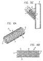
- FIG. 5Ais a perspective view of a stent having an angled proximal end.
- FIG. 5Bis a side elevational view of the proximal-angled stent of FIG. 5A depicting the distal end being transverse to the longitudinal axis of the stent, and the proximal end at an angle of less than 90°.
- FIG. 5Cis an elevational view of a bifurcation in which a prior art stent is implanted in the side-branch vessel.
- FIG. 5Dis an elevational view of a bifurcation in which a prior art stent is implanted in the side-branch vessel, with the proximal end of the stent extending into the main vessel.
- FIG. 5Eis an elevational view of a bifurcation in which the proximal-angled stent depicted in FIGS. 5A and 5B, is implanted in the side-branch vessel.
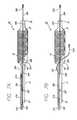
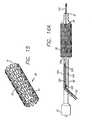
- FIG. 6Ais a perspective view depicting a main-vessel stent in which an aperture is formed on the outer surface of at least a portion of the stent.
- FIG. 6Bis a side elevational view of the main-vessel stent of FIG. 6A.
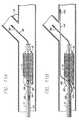
- FIG. 7Ais an elevational view, partially in section, of a side-branch catheter assembly depicting the distal end of the catheter with the expandable member and the second guide wire lumen attached thereto, for receiving the integrated stent-positioning guide wire, while the tracking guide wire is received by the main guide wire lumen.
- FIG. 7Bis an elevational view, partially in section, of the catheter assembly of FIG. 7A, in which the stent positioning guide wire is advanced out of the catheter.
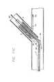
- FIG. 8is an elevational view, partially in section, of a side-branch catheter assembly depicting an expandable balloon having an angled proximal portion corresponding to the angle of the proximal-angled stent.
- FIG. 9Ais an elevational view of a bifurcated vessel in which a side-branch tracking guide wire has been advanced into a side-branch vessel, with the stent-positioning guide wire remaining within the catheter until the catheter assembly is just proximal to the side-branch vessel.
- FIG. 9Bis an elevational view of a bifurcation in which a side-branch tracking guide wire has been advanced through the patient's vascular system into a side branch, and a stent-positioning guide wire has been advanced through the patient's vascular system and into the main vessel distal to the ostium of the side-branch vessel.
- FIG. 10Ais an elevational view of a bifurcation in which the side-branch catheter assembly has been advanced in the patient's vasculature so that the proximal-angled stent mounted on the expandable member is positioned in the target area of the side-branch vessel.
- FIG. 10Bis an elevational view of the side-branch catheter assembly of FIG. 10A in which the proximal-angled stent has been expanded by the balloon portion of the catheter in the side-branch vessel.
- FIGS. 11A-11Dare partial elevational views in which the side-branch catheter assembly of FIG. 10A is used to implant the proximal-angled stent in the side-branch vessel where the proximal-angled stent is rotated to be properly aligned for implanting in the vessel.
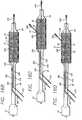
- FIGS. 12A-12Cdepict an elevational view, partially in section, ofa main-vessel catheter assembly in which the main vessel stent has an aperture on its outer surface.
- FIGS. 12D-12Fdepict an elevational view, partially in section, of the main-vessel catheter of FIGS. 12A-12C with a ramp to help orient and advance the guide wire through the aperture in the main-vessel stent.
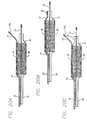
- FIGS. 12G-12Idepict an elevational view, partially in section, of an alternative to the main-vessel catheter of FIGS. 12A-12C in which the guide wire lumen is angled to pass under the stent and exit through the stent aperture.
- FIGS. 12J-12Ldepict an elevational view, partially in section, of an alternative to the main-vessel catheter of FIGS. 12A-12C in which a portion of the guide wire lumen passes under the stent.
- FIGS. 13A-13Eare elevational views, partially in section, depicting the main-vessel catheter assembly of FIG. 12A and the main-vessel stent in which two guide wires are used to correctly position the main vessel stent so that the aperture in the stent is aligned with the side-branch vessel.
- FIG. 14is an elevational view of a bifurcated vessel in which the proximal-angled stent is implanted in the side-branch vessel and a main vessel stent is implanted in the main vessel.
- FIG. 15is a perspective view of a main-vessel stent for deployment in the main vessel, where a targeted stent cell provides an opening through which a guide wire can pass.
- FIGS. 16A-16Dare elevational views, partially in section, of a main vessel catheter having the main vessel stent of FIG. 15 mounted thereon, and its relationship to the guide wire for advancing through a targeted stent cell.
- FIG. 17is an elevational view of a bifurcation in which a main-vessel stent is positioned in a main vessel so that it spans the opening to the side-branch vessel.
- FIG. 18is an elevational view of a bifurcation in which a main-vessel stent is implanted in the main vessel and a balloon catheter is partially inserted into a side-branch vessel to form an opening through the targeted stent cell of the main stent.
- FIGS. 19A-19Care elevational views of a bifurcation in which a main-vessel stent is first implanted in the main vessel and a catheter assembly next deploys a proximal-angled stent in a side-branch vessel.
- FIGS. 19D and 19Eare cross-sectional views looking down the side-branch vessel at an expanded main vessel prior art stent in which a random, sub-optimal stent cell was entered and expanded.
- FIGS 19Fis a cross-sectional view looking down the side-branch vessel at an expanded main-vessel stent in which a proper targeted stent cell was entered and expanded.
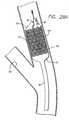
- FIG. 20Ais an elevational view, partially in section, depicting a main vessel catheter in which the main vessel stent is mounted over a positioning guide wire lumen.
- FIG. 20Bis an elevational view, partially in section, of a main vessel catheter depicting the main vessel stent mounted over a section of the positioning guide wire lumen, with a distal portion of the guide wire lumen associated with the distal tip of the catheter.
- FIG. 20Cis an elevational view, partially in section, of the catheter of FIG. 20B depicting the positioning guide wire advanced out of the positioning guide wire lumen.
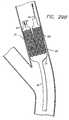
- FIG. 20Dis an elevational view, partially in section, depicting a main-vessel stent implanted in the main vessel without jailing or covering the side-branch vessel.
- FIG. 20Eis an elevational view, partially in section, depicting the main-vessel catheter of FIG. 20A having a ramp to assist in positioning the guide wire.
- FIG. 20Fis an elevational view, partially in section, of a distal angled stent being implanted in the main vessel without jailing the side-branch vessel.
- FIGS. 21 and 22are elevational views, partially in section, depicting an alternative to the main-vessel catheter of FIG. 20B in which the distal end of the guide wire lumen springs away from the expandable balloon.
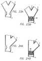
- FIGS. 23A-23B, 24A-24B, 25A-25B, and 26A-26Bare elevational views of various bifurcations which are indicated for receiving main vessel and side-branch vessel stents deployed by the catheters described.
- FIG. 27Ais an elevational view, partially in section, depicting an arrangement in which a Y-shaped catheter assembly deploys a Y-shaped stent in the bifurcation.
- FIG 27Bis an elevational view depicting an arrangement in which a dual balloon catheter assembly deploys a Y-shaped stent in the bifurcation.
- FIG. 28is an elevational view depicting the Y-shaped catheter assembly of FIG. 27A in which the stent is mounted on the balloon portions of the catheter.
- FIG. 29Ais an elevational view, partially in section of a bifurcation in which the Y-shaped catheter of FIG. 27A is delivering the stent in the bifurcated area, tracking over the wire that joins the two tips together.
- FIG. 29Bis an elevational view, partially in section, of a bifurcation in which the delivered Y-shaped balloon components have been released and spread apart by withdrawal of the tracking wire from the other balloon tip lumen.
- FIG. 29Cis an elevational view, partially in section, of the Y-shaped delivery catheter of FIG. 27A in which the Y-shaped balloon has been withdrawn proximal to the bifurcation, leaving the first wire in the right branch.
- FIG. 30is an elevational view, partially in section, of the Y-shaped delivery catheter of FIG. 27A in which the second guide wire is advanced into the left branch.
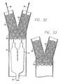
- FIG. 31is an elevational view depicting the Y-shaped catheter of FIG. 27A in which the Y-shaped stent is implanted in the side branch and main vessels of the bifurcation.
- FIG. 32is an elevational view, partially in section, depicting the Y-shaped catheter assembly of FIG. 27A in which the Y-shaped stent has been implanted and the balloon portions of the catheter have been deflated.
- FIG. 33is an elevational view depicting a bifurcated vessel in which the catheter of FIG. 27A has been withdrawn after implanting the Y-shaped stent.
- FIG. 34is an elevational view depicting a modified stent having an aperture in its sidewall and in which half of the stent has a heavy stent cell density while the other half of the stent has a light stent cell density.
- FIG. 35is an elevational view depicting the stent of FIG. 35 combined to form a stent having a heavy stent cell density in all portions.
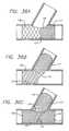
- FIG. 36Ais an elevational view depicting a bifurcation, in which the stent of FIG. 35 has been implanted so that the aperture corresponds to the side-branch vessel and the stent is implanted in the main vessel.
- FIG. 36Bis an elevational view depicting a bifurcating vessel in which the stent of FIG. 34 has been implanted so that the heavy stent cell density is in the side-branch vessel and the light cell density is in the main vessel.
- the aperturecorresponds to the continuing lumen of the main vessel.
- FIG. 36Cis an elevational view depicting a bifurcated vessel in which two stents of FIG. 34 have been implanted in the side-branch vessel and the main vessel respectively so that the light stent cell density of each overlaps with the light cell density of the other thereby creating cell density proximal to the bifurcation similar to the heavy cell density present in each limb distal to the bifurcation.
- FIGS. 1-4depict prior art devices which include multiple stents being implanted in both the main vessel and a side-branch vessel.
- a prior art "T" stentis implanted such that a first stent is implanted in the side branch near the ostium of the bifurcation, and a second stent is implanted in the main vessel, across the side-branch ostium.
- portions of the side-branch vesselare left uncovered, and blood flow to the side-branch vessel must necessarily pass through the main-vessel stent, causing possible obstructions or thrombosis.
- the prior art methodincludes implanting two stents side by side, such that one stent extends into the side-branch vessel and the main vessel, and the second stent is implanted in the main vessel. This results in a double-barreled lumen which can present problems such as thrombosis, and turbulence in blood flow.
- a first stentis implanted in the side-branch vessel, a second stent is implanted in a proximal portion of the main vessel, and a third stent is implanted distal to the bifurcation, thereby leaving a small gap between the stents and an uncovered luminal area.
- a proximal-angled stent 10is configured for deployment in a side-branch vessel 5.
- the proximal-angled stent 10includes a cylindrical member 11 having a longitudinal axis 12 which is an imaginary axis extending through the cylindrical member 11.
- a distal end 13 and a proximal end 14define the length of the cylindrical member 11.
- a first plane section 15is defined by a plane section through the distal end 13 of the cylindrical member, and second plane section 16 is defined by a plane section through the proximal end 14 of the cylindrical member.
- a second plane section 16defines an acute angle 18, which is the angle between the second plane section 16 and the longitudinal axis 12.
- FIGS. 5C and 5DIn treating the side-branch vessel 5, if a prior art stent is used in which there is no acute angle at one end of the stent to match the angle of the bifurcation, a condition as depicted in FIGS. 5C and 5D will occur. That is, a stent deployed in the side-branch vessel 5 will leave a portion of the side-branch vessel exposed (FIG. 5C), or as depicted in 5D, a portion of the stent will extend into the main-vessel 6. As depicted in FIG. 5E, the proximal-angled stent 10 has an acute angle 18 that approximates the angle formed by the bifurcation 4 of the side-branch vessel 5 and the main-vessel 6.
- the acute angle 18is intended to approximate the angle formed by the intersection of the side-branch 5 and the main-vessel 6.
- the angle between the side-branch vessel 5 and the main-vessel 6will vary for each application, and for the present purposes, should be less than ninety degrees (90°). If there is a ninety degree (90°) angle between the side-branch vessel and the main vessel, a conventional stent having ends that are transverse to the stent longitudinal axis, would be suitable for stenting the side-branch vessel.
- the proximal-angled stentcan be implanted in the side-branch vessel to treat a number of angulated ostial lesions including, but not limited to, the following:
- the proximal-angled stenttypically can be used as a solo device to treat the foregoing indications, or it can be used in conjunction with the main-vessel stent described herein for stenting the bifurcation.
- the main-vessel stent 20is configured for deployment in the main vessel 6.
- the main-vessel stent 20includes a cylindrical member 21 having a distal end 22 and a proximal end 23.
- the main-vessel stent 20includes an outer wall surface 24 which extends between a distal end 22 and a proximal end 23 and incorporates an aperture 25 on the outer wall surface 24.
- the aperture 25is configured so that, upon expansion, it approximates the diameter of the expanded proximal end 14 of the proximal-angled stent 10.
- the aperture 25is aligned with the side-branch vessel 5 and the proximal end 14 of the proximal-angled stent 10, thereby providing an unrestricted blood flow path from the side-branch vessel to the main vessel.
- the main-vessel catheterallows selection and positioning of an aperture at the side-branch ostium. Further, it provides for the positioning ofa guide wire during main-vessel stent deployment which can be used for additional intervention if necessary.
- access to a side-branchis through a randomly selected stent element ("cell"), and is only possible after deployment of the stent.
- the precise positioning of aperture 25 in the stent illustrated in FIGS. 6A and 6Bis optional and the aperture 25 could be positioned either closer to the proximal end or closer to the distal end of the main vessel stent 20.
- the proximal-angled stent 10 and the main-vessel stent 20can be formed from any of a number of materials including, but not limited to, stainless steel alloys, nickel-titanium (NiTi) alloys (the NiTi can be either a shape memory type or pseudoelastic), tantalum, tungsten, or any number of polymer materials. Such materials of manufacture are known in the art. Further, the proximal-angled stent 10 and the main-vessel stent 20 can have virtually any pattern known to prior art stents.
- the proximal-angled stent 10 and the main-vessel stent 20are formed from a stainless steel material and have a plurality of cylindrical elements connected by connecting members, wherein the cylindrical elements have an undulating or serpentine pattern.
- a stentis disclosed in U.S. Patent No. 5,514,154 and is manufactured and sold by Advanced Cardiovascular Systems, Inc., Santa Clara, California. The stent is sold under the tradename MultiLink® Stent.
- Such stentscan be modified to include the features of the proximal-angled stent 10 (the angulation) and the main-vessel stent 20 (the aperture).
- the proximal-angled stent 10 and the main-vessel stent 20preferably are balloon-expandable devices that are mounted on a balloon portion of a catheter and crimped tightly onto the balloon to provide a low profile delivery diameter.
- the balloonis expanded, thereby expanding the stent beyond its elastic limit into contact with the vessel.
- the balloonis deflated and the balloon and catheter are withdrawn from the vessel, leaving the stent implanted.
- Deployment of the angled and main-vessel stentsis accomplished by a stent delivery system adapted specifically for treating bifurcated vessels.
- the proximal-angled stent and the main-vessel stentcould be made to be either balloon expandable or self-expanding.
- the side-branch stent delivery assembly 30is provided and includes side-branch catheter 31.
- the side-branch catheterincludes a distal end 32 which is configured for delivery into the patient's vasculature and a proximal end 33 which remains outside the patient.
- a first guide wire lumen 34Aextends through at least a portion of the side-branch catheter 31, depending on the type of catheter ( e.g. , rapid exchange, over-the-wire, etc.) desired for a particular application.
- the first guide wire lumen 34Apreferably is defined by a distal end 34B and a side port 34C, which is typical of the so-called rapid-exchange-type catheters.
- a slitextends from the side port 34C to just proximal of the balloon portion of the catheter, so that the catheter can be rapidly exchanged during a medical procedure, as is known.
- the expandable member 35which typically is a non-distensible balloon, has a first compressed diameter for delivery through the vascular system, and a second expanded diameter for implanting a stent.
- the expandable member 35is positioned near the distal end 32, and in any event between the distal end 32 of the first catheter 31 and the side port 34C.
- a tracking guide wire 36A having a distal end 36B and a proximal end 36Cextends through the first guide wire lumen 34A.
- the tracking guide wire 36Apreferably is a stiff wire having a diameter of 0.356 mm (.014 inch), but can have a different diameter and stiffness as required for a particular application.
- An especially suitable guide wirecan be one of those manufactured and sold under the tradenames Sport® and Ironman®, manufactured by Advanced Cardiovascular Systems, Inc., Santa Clara, California.
- the tracking guide wire 36Ais sized for slidable movement within the first guide wire lumen 34A.
- the side-branch delivery assembly 30further includes a second guide wire lumen 39A, which is associated with the expandable member 35.
- the second guide wire lumen 39Aincludes an angle portion 39B and a straight portion 39C, and is firmly attached to an outer surface 40 of the catheter 31, at a point just proximal to the expandable member 35.
- An integrated stent-positioning guide wire 41Ais sized for slidable movement within the second guide wire lumen 39A.
- a slit 39Dis formed in the lumen 39A near its distal end, so that the stiff guide wire 41A can bow outwardly as shown in FIG. 7B. The portion of the guide wire 41A that bows out of the slit 39D will limit the advancement of the catheter 31, as will be further described infra.
- the integrated stent-positioning guide wire 41 Ahas a distal end 41B, and a proximal end 41C which extends out of the patient. Again, it is preferred that the integrated stent-positioning guide wire, 41A be a fairly stiff wire as previously described, for the reasons set forth below in delivering and implanting the stents in the bifurcation.
- the catheter 31can have an angled expandable member 42 as depicted in FIG. 8.
- the proximal end of the expandable memberis angled to coincide with the angle of the proximal-angled stent 10 (not shown in FIG. 8 for clarity).
- This arrangementis particularly useful in delivering the angled stent since the second guide wire lumen 39A, and its angled portion 39B, have the same angle as the stent and the proximal end of the expandable member.
- the proximal-angled stent 10is mounted on the side-branch catheter 31 and implanted in the side-branch vessel 5.
- the method of achieving proximal-angled stent implantationis as follows.
- the proximal-angled stent 10first is crimped tightly onto the expandable member 35 for low-profile delivery through the vascular system.
- the distal end 36B of the guide wire 36Ais advanced into the side-branch vessel 5 and distally of the target area, with the proximal end 36C remaining outside the patient.
- the side-branch catheter 31then is advanced within a guiding catheter (not shown) along the tracking guide wire 36A until the distal end 32 of the catheter is just proximal (about 1 cm) of entering the side-branch vessel 5.
- the guide wire 41Aresides in the second guide wire lumen 39A so that the distal end 41B of the wire preferably is near, but is not in, the angled portion 39B of the guide wire lumen 39A. This method of delivery prevents the two guide wires from wrapping around each other, the guide wire 41 A being protected by the catheter during delivery.
- the distal end 41B of the integrated stent positioning guide wire 41Athen is advanced by having the physician push the proximal end 41 C from outside the patient's body.
- the distal end 41B of the integrated stent-positioning guide wiretravels through the guide wire lumen 39A and the angled portion 39B and passes close to the proximal end 14 of the angled stent 10 and the expandable member 35 and exits at the angled portion 39B of the second guide wire lumen 39B.
- the stiffness of the wirecauses it to bow outwardly through the slit 39D in the distal portion of the second guide wire lumen 39A.
- the positioning guide wire 41 Abows outwardly and, due to its stiffness, provides a bumper against the ostium of the side-branch vessel to assist in positioning and deploying the stents.
- the stent-positioning guide wire 41Ais advanced in the main vessel until the distal end 41B is distal to the side-branch vessel 5.
- the catheterthen is advanced into the side-branch vessel 5 until resistance is felt, caused by the stent-positioning guide wire 41 A pushing up against the ostium of the side-branch vessel 5.
- the stent-positioning wire 41Ais relatively stiff, as is the tracking guide wire 36A, so that each can properly orient the side-branch catheter 31 as it is advanced into the side-branch vessel 5.
- the angled portion 39B of the second guide wire lumen 39Ais angled to assist in rotating the side-branch catheter 31 into proper position into the side-branch vessel 5. If the stent approaches the side-branch vessel 5 in the incorrect position, as depicted in FIGS. 11A-11B, the stent-positioning wire 41A would be forced to make a very acute angle.
- the wire stiffnessprevents this from happening and causes the wire to assume the position of least stress. As is illustrated in FIGS.
- the wire 41Acreates a torque on the angled portion 39B, causing the guide wire lumen 39A and the side-branch catheter 31, with the proximal-angled stent 10, to rotate into the correct position.
- the slit 39Dis formed on the outer surface 40 of the catheter 31 near the angled portion 39B, so that the stent-positioning guide wire 41A can bow outwardly out of the slit 39D, thereby increasing the ability to torque the catheter and the proximal-angled stent.
- the proximal-angled stent 10 mounted on the expandable member 35is aligned across the target area, and viewed under fluoroscopy, the acute angle 18 on the proximal end of the proximal-angled stent is aligned at the intersection of the side-branch vessel 5 and the main-vessel 6 (the ostium of the side-branch vessel) so that the proximal-angled stent completely covers the target area in the side-branch vessel 5, yet does not extend into the main-vessel 6, thereby compromising blood flow.
- the expandable member 35which typically is a non-distensible balloon, is expanded by known methods, thereby expanding the proximal-angled stent into contact with the side-branch vessel 5, and thereby implanting the proximal-angled stent in the side-branch vessel. Thereafter, the expandable member 35 is deflated and the side-branch catheter assembly 31 is withdrawn from the patient's vasculature.
- the side-branch catheter 31is designed so that both the tracking guide wire 36A and the stent-positioning guide wire 41A can be left in the vessels in which each respectively has been deployed, in the event sequential or simultaneous high pressure balloon inflation be required in each of the vessels in order to complete the stenting procedure.
- the integrated positioning wirecan be unzipped through the slit (not shown) from the proximal 100 cm of the catheter, thereby allowing it to act as a rapid exchange wire.
- high pressure balloonsare inflated simultaneously in the main-vessel stent and the proximal-angled stent, in order to avoid deforming one stent by unopposed balloon inflation occurring in the other one. This additional step is a matter of physician preference.
- the side-branch vessel 5can be stented without the need for stenting the main vessel, as shown in FIGS. 11A-11D.
- the main-vessel 6also can be stented after stenting the side-branch vessel.
- a main-vessel catheter assembly 50is provided for implanting the main-vessel stent 20, as depicted in FIGS. 12A to 13E.
- the main-vessel catheter 50includes a distal end 51 which is configured for advancement within the patient's vasculature, and a proximal end 52 which remains outside the patient.
- the main-vessel catheterincludes a guide wire lumen 53A having a distal end 53B and a side port 53C, which is proximal to the balloon portion of the catheter.
- the side port 53Cis provided in a so-called rapid-exchange catheter system which includes a slit (not shown) as is known in the art.
- An expandable member 54is located near the distal end 51 of the main-vessel catheter 50.
- the expandable member 54is a non-distensible balloon of the type known in the art for delivering and expanding stents.
- the positioning guide wire lumen 55Ais positioned partly on the catheter shaft and partly on the expandable member 54, and is configured for slidably receiving the integrated stent-positioning guide wire 56A.
- the integrated stent-positioning guide wire 56Aresides in the positioning guide wire lumen 55A and only during stent delivery is it then advanced into and through the angled portion 55B of the lumen.
- FIGS. 12D-12FOther preferred arrangements, for implanting the main-vessel stent 20 in the main vessel 6 are depicted, for example, in FIGS. 12D-12F.
- This arrangementis identical to that depicted in FIGS. 12A-12C, with the addition of a ramp 57 which is mounted on the balloon 54 and which provides a slight incline for the integrated stent-positioning guide wire 56A as it exits the positioning guide wire lumen 55A.
- the distal portion 56B of the guide wirewill move radially outwardly which helps position the guide wire and orient it into the side-branch vessel.
- FIGS. 12D-12FThis arrangement is identical to that depicted in FIGS. 12A-12C, with the addition of a ramp 57 which is mounted on the balloon 54 and which provides a slight incline for the integrated stent-positioning guide wire 56A as it exits the positioning guide wire lumen 55A.
- the distal portion 56B of the guide wirewill move radially outwardly which helps
- the guide wire lumen 55Apasses underneath the main-vessel stent 20 and on top of the balloon 54.
- the distal end angled portion 55Bcurves along the balloon so that, as the distal end of the guide wire 56B advances out of the distal end angled portion 55B of the lumen, the distal end of the guide wire is traveling radially outwardly so that it can more easily locate and advance into the side-branch vessel 5.
- the positioning guide wire lumen 55Ais positioned under the stent 20 and terminates at the distal end angled portion 55B in the middle of the aperture 25.
- the distal end angled portion 55B of the guide wire lumenwill spring outwardly, facilitating the advancement of the distal portion ofthe integrated stent positioning guide wire 56B into the side branch vessel.
- a distal guide wire lumen 58is attached to the outer surface of balloon 54 and extends from the aperture 25 to essentially the distalmost end of the catheter.
- the integrated stent-positioning guide wire 41 A of the side-branch delivery assembly 41 Aremains in position in the main-vessel 6, while the side-branch tracking guide wire 36A is withdrawn from the patient.
- the main-vessel catheter 50is back loaded onto the guide wire 41A by inserting the proximal end 41C of the wire into the distal end of the catheter and into the guide wire lumen 53A.
- the main-vessel catheter 50is advanced over the guide wire 41A and viewed under fluoroscopy until the main-vessel stent 20 is positioned in the main-vessel 6, just proximally of the side-branch vessel 5.
- the distal portion 56B of the integrated stent-positioning guide wire 56A of the main-vessel catheterthen is advanced by the physician who pushes on the proximal portion 56C from outside the patient's body.
- the distal portion 56B of the guide wire 56Aadvances into and through the positioning guide wire lumen 55A, and passes underneath the proximal end of the main-vessel stent 20 and exits the angled portion 55B of the positioning guide wire of the lumen 56A and enters the side-branch vessel 5.
- the main-vessel catheter 50then is advanced distally into the main vessel until resistance is felt, caused by the integrated stent-positioning guide wire of the main-vessel catheter 56A pushing up against the ostium of the side-branch vessel.
- the stiffness of the stent-positioning guide wire 56Acauses the main-vessel catheter 50, with the main-vessel stent 20 thereon, to rotate, so that the aperture 25 faces the ostium of the side-branch vessel 5 where the proximal-angled stent 10 already is implanted.
- the expandable member 54which typically is a non-distensible expandable balloon, is inflated, thereby expanding the main-vessel stent 20 into contact with the main-vessel 6.
- the aperture 25correspondingly expands and, when properly aligned, provides a blood flow path between the aperture 25 and the proximal-angled stent 10 implanted in the side-branch vessel 5.
- the positioning guide wire lumen 55Ais positioned on the expandable member 54, such that when the expandable member is inflated, the positioning guide wire lumen 55A does not interfere with the implanting of the main-vessel stent 20.
- the expandable member 54is deflated, and the main-vessel catheter 50 is withdrawn from the patient.
- the bifurcated vesselhas been fully covered by the stents, the side-branch vessel 5 being covered by the proximal-angled stent 10, and the main-vessel 6 being covered by the main-vessel stent 20, so that no portion of the bifurcation 4 is left uncovered and there is no overlap in the implanted stents.
- the integrated stent-positioning guide wire 41A of the side-branch delivery assemblywhich here serves as the tracking guide wire, is advanced through the positioning guide wire lumen 55A and the distal guide wire lumen 58 attached to the balloon so that the guide wire advances distally of the distal end 51 of the main-vessel catheter.
- the guide wire distal end 41Bis advanced into the main vessel so that it is distal ofthe side-branch vessel 5.
- the integrated stent-positioning guide wire 56Awhich until this point has remained within the guide wire lumen 53A (see FIG. 12K), is advanced distally as depicted in FIG.
- the guide wire 41Athen is withdrawn proximally through the guide wire lumen 58 until guide wire distal end 41B is able to exit the guide wire lumen distal end angled portion 55B, as shown in FIG. 12L. Because the angled portion of the positioning guide wire lumen 55B is preformed and has bias, it will spring outwardly. The guide wire 41A then can be advanced into the side-branch vessel for further positioning.
- the distal portion 41B of the guide wirewill push against the ostium of the side-branch vessel thereby insuring the location of the main-vessel stent 20 and, importantly, the aperture 25 will align with the opening to the side-branch vessel 5.
- a non-angulated stentcan be implanted using the catheter system of FIGS. 7A-11D for stenting a side-branch vessel having an origin approaching ninety degrees (90°) in its takeoff from the main vessel.
- the positioning wireserves solely to arrest the forward movement of the stent precisely at the origin of the vessel for more precise positioning.
- the acute angle 18is appropriate for a bifurcated vessel 4 in which the angulation is the acute angle 18, or less than ninety degrees (90°).
- considerationcould be given to standard thirty degree (30°), forty-five degree (45°), and sixty degree (60°) angled stent designs for the proximal-angled stent 10, which should provide sufficient luminal wall coverage.
- the proximal-angled stent 10has a wide range of applicability and can be used for stenting ostial side-branch lesions, ostial circumflex or left anterior descending (LAD) lesions where the bifurcation is an acute angle, or less than ninety degrees (90°), and ostial lesions involving the angulated origin of a right coronary or vein graft.
- the stentsprovide full coverage of the ostial intima without protruding into the main vessel and without compromising subsequent access to the distal portion of the main vessel.
- the positioning guide wire lumen 39A, on the side-branch catheter 31, and the positioning guide wire lumen 55A, on the main-vessel catheter 50can be radiopaque, or can have a radiopaque marker associated therewith so that each is visible under fluoroscopy.
- the proper orientationcan be determined more easily by viewing the position of the positioning guide wire lumen 39A in connection with the main-vessel 6 or the positioning guide wire lumen 55A in connection with aligning the aperture 25 with the side-branch vessel 5.
- the positioning guide wire 56A for positioning the main-vessel stent 20 and the positioning guide wire 41A for positioning the angled stent 10either are radiopaque or have radiopaque portions, such as gold markers, to assist in positioning and orienting the catheters and stents during deployment and implantation.
- While the foregoing descriptionincludes implanting the proximal-angled stent 10 in the side-branch vessel 5 prior to implanting the main-vessel stent 20 in the main-vessel 6, in an alternative arrangement, the order of the implanting procedures can be reversed. However, it should be understood that by implanting the main-vessel stent 20 in the main-vessel 6, and subsequently by implanting the proximal-angled stent 10 in the side-branch vessel 5, the aperture 25 must he carefully aligned with the side-branch vessel 5 so that the side-branch catheter 31 can be advanced through the expanded main-vessel stent 20 and the aperture 25 and into the side-branch vessel 5 for implanting the proximal-angled stent 10.
- the side-branch catheter 31 and the main-vessel catheter 50have been described herein as being of the rapid-exchange type, they also can be of a conventional over-the-wire-type catheter.
- the guide wire lumenextends from the distal end of the catheter to the proximal end with no side port as is found in the rapid-exchange-type catheters.
- Typical of over-the-wire-type cathetersis the type disclosed in U.S. Patent Nos. 4,323,071 and B1 4,323,071, commonly assigned and commonly owned by Advanced Cardiovascular Systems, Inc., Santa Clara, California.
- a main-vessel unmodified stent 60can be configured without the side aperture 25 of the main-vessel stent 20.
- the individual strut members 61 of unmodified stent 60expand sufficiently to permit a balloon catheter to be inserted therethrough, and expanded, to form an aperture which corresponds to the opening to the side-branch vessel 5.
- the side-branch vessel 5is first stented as described, for example, in the manner shown in FIGS. 9A through 11D. Thereafter, the main-vessel 6 is stented with the unmodified main-vessel stent 60, which does not have an aperture formed in the side of the stent. As shown in FIGS. 15-18, the unmodified stent 60 is mounted on the expandable portion 54 of the main-vessel catheter 50. The main-vessel catheter 50 is back loaded onto the proximal end of the integrated stent-positioning guide wire of the side-branch delivery assembly 41A which already is in position in the main vessel.
- the main-vessel catheter 50is advanced over the guide wire and is viewed under fluoroscopy until the stent 60 is positioned in the main vessel about 1 cm proximally of the side-branch vessel.
- the distal end 56B of the integrated stent-positioning guide wire 56Athen is advanced by the physician by pushing the proximal end 56C from outside the body.
- the distal end of 56B the guide wire 56Atravels through the guide wire lumen 55A, passes underneath the proximal end of the unmodified stent 60, exits the angled end of the lumen 55B, and enters the side-branch vessel 5.
- the main-vessel catheter 50then is advanced distally into the main vessel until resistance is felt, caused by the stent-positioning guide wire 56A pushing up against the ostium of side-branch vessel 5.
- the stiffness of the stent-positioning guide wire 56Acauses the main-vessel catheter 50 bearing the unmodified stent 60 to rotate so that a stent cell 62 is precisely facing the ostium of the side-branch vessel 5.
- the expandable member 54is expanded by known means so that the unmodified stent 60 expands into contact with the main-vessel 6.
- the expandable member 54then is deflated, and the catheter 50 is withdrawn from the patient's vascular system, leaving the guide wire 56A in the side-branch vessel 5.
- a third catheter 65which can be a standard PTCA catheter, is back loaded onto the integrated stent-positioning guide wire 56A, already in side-branch vessel 5, and is advanced within the patient's vascular system over the guide wire. As shown in FIG.
- the distal end 66 of the catheter 65is advanced over the guide wire 56A until the distal end 66 of the catheter 65 begins to pass through the cell 62 of the unmodified main-vessel stent 60 and to enter the side-branch vessel 5.
- the catheter 65can be of a known type used in angioplasty, as described above, having a non-distensible member or balloon 67. Once the balloon 67 is positioned through the stent cell 62 and in the opening of the side-branch vessel 5, it is expanded, thereby expanding some of the struts 61 comprising the unmodified stent 60 and forming a substantially circular opening from the main-vessel 6 through the unmodified stent 60 and into the side-branch vessel 5.
- the balloon 67spreads apart some of the struts of the unmodified stent 60 to form an opening in the stent 60 that corresponds to the opening to the side-branch vessel 5, thereby providing a clear blood flow path between the main vessel and the side-branch vessel.
- the unmodified main-vessel stent 60is positioned so that it crosses the opening to the side-branch vessel 5.
- a particularly well-suited stent for this arrangementincludes a stent distributed under the tradename MultiLink® Stent, manufactured by Advanced Cardiovascular Systems, Inc., Santa Clara, California.
- the unmodified stent 60is implanted first, then the side-branch proximal-angled stent 10 is implanted.
- the unmodified stent 60can be mounted on the expandable member 54 of the main-vessel catheter 50.
- the main-vessel catheter 50is back loaded onto the proximal end of the guide wire 41A.
- the main-vessel catheter 50is advanced over the guide wire 41A and is viewed under fluoroscopy until the unmodified stent 60 is positioned in the main-vessel 6, proximally of side-branch vessel 5.
- the distal end of the integrated stent-positioning guide wire 56Bthen is advanced by the physician, who pushes the proximal end 56C from outside the patient's body.
- the distal end 56B of the guide wire 56Atravels through the second guide wire lumen 55A, passes underneath the proximal end of the unmodified stent 60, exits the angled end of the lumen 55B and enters the side-branch vessel 5.
- the main-vessel catheter 50then is advanced distally into the main vessel until resistance is felt, caused by the stent-positioning guide wire 56A pushing up against the ostium of the side-branch vessel 5.
- the stiffness of stent-positioning guide wire 56Acauses the main-vessel catheter 50 bearing the unmodified stent 60 to rotate, so that a stent cell 62 is precisely facing the side-branch vessel 5 ostium.
- the expandable member 54is expanded by known means so that the unmodified stent 60 expands into contact with the main-vessel 6.
- the expandable member 54then is deflated, and the catheter 50 is withdrawn from the patient's vascular system, leaving the guide wire 56A in the side branch 5.
- a third catheter 65which can be a standard PTCA catheter, is back loaded onto the guide wire 56A, which already is in the side-branch vessel 5, and is advanced within the patient's vascular system over the guide wire.
- the distal end 66 of the catheter 65is advanced over the guide wire 56A until the distal end 66 of the catheter begins to pass through the struts 61 of the stent cell 62 of the unmodified main-vessel stent 60 and then to enter the side-branch vessel 5.
- the catheter 65can be of a known type used in angioplasty, as described above, having a non-distensible member or balloon 67.
- the balloon 67is positioned through a stent cell 62 into the opening of the side-branch vessel 5, it is expanded, thereby expanding some of the struts comprising the unmodified stent 60 and forming a substantially circular opening from the main-vessel 6 through the unmodified stent 60 and into the side-branch vessel 5.
- the balloon 67spreads apart the struts 61 of the unmodified stent 60 to form an opening in the unmodified stent which corresponds to the opening to the side-branch vessel 5, thereby providing a clear opening for further stenting of the side-branch vessel 5.
- the side-branch vessel 5is stented in the same manner as is described with respect to FIGS. 9-11.
- the unmodified main-vessel stent 60already is implanted when the catheter 31 is advanced into the side-branch vessel 5.
- the side-branch catheter 31is back loaded onto the tracking guide wire 36A already in the side-branch vessel 5.
- the side-branch catheter 31then is advanced until the distal tip of the side-branch catheter 31 just enters the ostium of the side-branch vessel 5.
- the distal end 41B of the integrated stent-positioning guide wire 41Athen is advanced by the physician, who pushes the proximal end 41C of the guide wire from outside the patient's body.
- the distal end 41B of the integrated stent-positioning guide wire 41Atravels through the second guide wire lumen 39A and the angled portion 39B thereof passes close to the proximal end of the proximal-angled stent 10 and the expandable member 35, and exits the angled portion ofthe second guide wire lumen 39B.
- the stent-positioning guide wire 41Ais advanced until the distal end 41B is distal of the side-branch vessel 5.
- the catheterthen is advanced into the side-branch vessel until resistance is felt, caused by the stent-positioning guide wire 41 A pushing up against the ostium of the side-branch vessel.
- the stent-positioning wire 41Ais relatively stiff, as is the tracking guide wire 36A, so that each properly can orient the side-branch catheter 31 as it is advanced into the side-branch vessel.
- the angled portion 39B of the second guide wire lumen 39Ais angled to assist in rotating the side-branch catheter into proper position into the side-branch vessel 5. If the stent approaches the side-branch vessel in the incorrect position, the stent-positioning wire 41A would be forced to make a very acute angle.
- the guide wire 41Acreates a torque on the angled portion of the second guide wire lumen 39B, causing the guide wire lumen 39A and the side-branch catheter 31 with the proximal-angled stent 10 to rotate into the correct position.
- the expandable member 35is expanded so that the proximal-angled stent expands into contact with the side-branch vessel 5, making sure that the proximal end 14 of the proximal-angled stent 10 covers and is aligned with the side-branch vessel 5 at the bifurcation 4.
- the proximal end 14is aligned so that it coincides with the acute angle 18, thereby ensuring that all portions of the side-branch vessel 5 are covered by the proximal-angled stent, including the area where the side-branch vessel 5 meets the main-vessel 6.
- An unobstructed blood-flow pathnow exists between the expanded unmodified stent 60 and the main-vessel 6 through the opening previously formed and into the side-branch vessel 5 and through the implanted proximal-angled stent 10.
- FIGS. 19D and 19Eshow what can happen when an inappropriate target stent cell is selected randomly and then expanded by a high pressure balloon.
- FIG. 19Dwhich is a view looking down the side-branch vessel 5, in cross-sections, at a prior art stent 68, the physician randomly selects the stent cell 69 which is a sub-optimal cell to expand with the balloon portion of a catheter.
- the target stent cell 62is the optimal cell for expansion, and is preselected with a guide wire that is in place before stent deployment (that same wire remaining in place for subsequent access), and is oriented optimally with respect to the ostium of the side-branch vessel prior to deployment.
- the resulting expansionguarantees an optimal aperture where the stent struts have been expanded, providing a blood flow path from the main vessel to the side-branch vessel.
- the main-vessel catheter 70includes an expandable member 71 near its distal end, while the proximal end of the catheter (not shown) is similar to those previously described and either can be of the rapid-exchange or over-the-wire type.
- the catheter 70includes a tracking guide wire lumen 72 for slidably receiving a tracking guide wire 73, the lumen 72 extending at least partially through the catheter in the rapid-exchange configuration, and all the way through the catheter in the over-the-wire configuration.
- the catheteralso includes a positioning guide wire lumen 74 that is associated with the outer surface of the catheter and which is adapted to -receive positioning guide wire 77.
- the positioning guide wire lumen 74extends onto and is attached to at least a portion of the expandable member 71. As shown in FIG. 20A, the positioning guide wire lumen 74 extends along the expandable member and ends just at the distal taper of the expandable member. As depicted in FIGS. 20B and 20C, the positioning guide wire lumen 74 can be formed of two sections, namely, a distal section 75 attached to the distal tip of the catheter, and a proximal section 76 extending along and attached to the expandable member and the catheter. As previously described, the two guide wires 73,77 are intended to be relatively stiff wires so that each can more easily maneuver the catheter. In these embodiments, a stent 78 is mounted on the expandable member 71 and over the positioning guide wire lumen 74. The positioning guide wire 77 is configured for slidable movement within the positioning lumen 74.
- the tracking guide wire 73first is positioned within the main vessel as previously described. The catheter then is back loaded onto the guide wire by inserting the wire into the tracking guide wire lumen 72 and advancing the catheter into the patient's vascular system. At this point, the positioning guide wire 77 resides within the positioning guide wire lumen 74 and is carried into the main vessel where it will be released and advanced. Once the catheter has reached the target area, the positioning guide wire 77 is advanced distally out of the positioning guide wire lumen (for the situation illustrated in FIG. 20A) or pulled back slightly out of the distal section 75 of the positioning guide wire lumen (for the situation illustrated in FIGS.
- FIGS. 20A-20Cis designed to allow deployment of a stent very near but not "snowplowing" a bifurcation or side branch and is configured for treating bifurcations as depicted in FIGS. 23A-25B.
- a commonly encountered situation in which the catheter 70 would be usedis a left anterior descending (LAD) artery that has disease right at, and proximal to, the diagonal take-off. After a careful look at multiple views, the physician should be convinced that the diagonal is spared, but the lesion is very close to and or is immediately adjacent the diagonal take-off, as shown in FIG. 20D. It is very difficult to position a standard stent in the LAD and to be certain that the lesion is fully covered and the diagonal is not snowplowed or jailed.
- the catheter 70having one wire in the LAD (main vessel) and the other in the diagonal (side-branch vessel), would allow precise definition of the bifurcation and would avoid these problems.
- a square stent 78Awhich has both ends transverse to the stent axis, could be deployed just proximal to the carina, in which case the stent distal end may need to be flared a bit, or more likely, relaxed back to where the positioning guide wire 77 is resting against the proximal aspect of the ostium, visually defining the ostium in relationship to the stent and allowing precise deployment.
- FIGS. 20E, 21 and 22Several alternative arrangements of the main-vessel catheter 70 shown in FIG. 20A, are depicted in FIGS. 20E, 21 and 22.
- the catheter device shown in FIG. 20Eis similar to that shown in FIG. 20A, with the exception that the ramp 57 is employed just distally of the distal end of the guide wire lumen 74 so that as the guide wire 77 exits the lumen, it will move outwardly along the ramp 57 so that it more easily advances into the side-branch vessel.
- FIGS. 21 and 22which are similar to the catheter described and depicted in FIGS. 20B and 20C, it is intended that the guide wire 77 move outwardly so that it can more easily be advanced into the side-branch vessel 5.
- the distal end of the guide wire lumen 74is biased outwardly as shown in FIG. 22, so that as the guide wire 77 is pulled back from the lumen 75, the distal end of guide wire lumen 74 will spring outwardly thereby assisting the guide wire 77 in moving radially outwardly to be positioned in the side-branch vessel.
- the catheter 70In order to implant a square main-vessel stent 78A in a main vessel, where the disease is at or just proximal to the side-branch vessel, the catheter 70 as depicted in FIGS. 21 and 22 is well suited. For example, the catheter 70 is advanced over the guide wire 77 until the catheter is positioned just proximal of the side-branch vessel. The tracking guide wire 73, which up to this point has been contained within the main-vessel catheter 70, is advanced into the main vessel so that it is distal of the side-branch vessel.
- the guide wire 77then is withdrawn proximally so that its distal end 77A is withdrawn from the distal section 75 of the positioning guide wire lumen 74, whereupon the guide wire 77 and the distal end of the guide wire lumen 74 spring outwardly, thereby assisting the positioning of the guide wire 77 into the side-branch vessel.
- the guide wire 77then is advanced into the side-branch vessel and the main-vessel catheter 70 is advanced so that the guide wire 77 rests on the proximal ostium of the side-branch vessel, wherein the square stent 78A then can be expanded to cover the diseased portion, but not to span or cover ( i.e. , "jail") the opening to the side-branch vessel.
- the catheter system as depicted in FIG. 20Acan be incorporated but to implant a distal-angled stent 78B rather than square stent 78A.
- the stent 78Bhas an angle at its distal end which coincides with the opening to the side-branch vessel so that the diseased portion of the main vessel is covered by the distal end of the stent, with the angle of the stent angled proximally so that the side-branch vessel is not covered or jailed.
- Various alternatives of the square stent 78A and the distal-angled stent 78Bcan be used for treating various conditions as depicted in FIGS. 23A through 26B.
- a dual balloon Y-shaped catheter assemblyis provided to stent a bifurcation.
- a Y-shaped stentis implanted to cover the bifurcation.
- the catheter 90includes first and second expandable members 91,92 that are configured to reside side by side (Y-shaped) for low profile delivery and to spring apart for implanting the stents.
- a locking ring 93may be used to assist in holding the expandable members together until just prior to deployment, at which time the locking ring can be removed.
- a guide wire lumen 95extends at least through a portion of the catheter and slidably receives a guide wire 96.
- the second guide wire lumen 98extends at least through a portion ofthe catheter and slidably receives the second guide wire 99.
- the second guide wire lumen 98includes distal section 98A and 98B.
- a Y-shaped stent 100is mounted on the first and second expandable members 91, 92.
- the second guide wire 99In the method of stenting the bifurcated vessels shown in FIGS. 29 to 33, the second guide wire 99, previously positioned distal to the bifurcation in one limb (perhaps the limb most vulnerable to problems for wire re-crossing), is back loaded into the lumens 98A and 98B and the catheter 90 is advanced over the second guide wire 99 so that the catheter is advanced distally beyond the bifurcation.
- the guide wire 96which has been contained in the lumen 95 to this point, is advanced along the side of the guide wire 99.
- the guide wire 99then is withdrawn until its distal end pulls out of the distal section 98A of the second guide wire lumen 98.
- the first and second expandable members 91,92which normally are biased together, are released and now spring apart.
- the guide wire the guide wire lumen for which is most distant (lateral) to the bifurcation(in this case the guide wire 96) then is advanced into the distal vessel and the other guide wire (in this case the second guide wire 99) is withdrawn as illustrated in FIG. 29B.
- the catheterthen is withdrawn proximally so that the expandable members 91, 92 are now proximal to the bifurcation as depicted in FIG. 29C and the other guide wire (in this case, the second guide wire 99) is advanced into the other limb of the bifurcation as shown in FIG. 30.
- the catheter 90then is advanced distally over both guide wires 96 and 99, as shown in FIG. 31, until the stent 100 is positioned in the bifurcation of the intersection of vessels 105,106. Due to the appropriate wire selection, rotation of no more than ninety degrees (90°) will be required.
- a stent 100is implanted by inflating the expandable members 91,92 in a known manner. The expandable members then are deflated, and the catheter is withdrawn from the patient.
- the arrangement of the guide wires 96 and 99 and the respective lumens of eachpermit single unit transport of a Y-stent to the distal target site without wire wrapping problems and further allows for minimal requirements of rotation of the device (less than ninety degrees (90°)) for optimal deployment (allowing minimal twist deformity).
- the guide wiresmay be left in place for further intervention such as for finishing the stents with simultaneous high pressure balloon inflation.
- a pair of stents as depicted in FIGS. 34-36 having varying stent cell densityare implanted in a bifurcated vessel, as depicted in FIGS. 34-36C.
- an apertured stent 115is provided in which an aperture 116 is positioned on its outer surface.
- the stent 115includes areas of heavy stent cell density 117 and areas of light stent cell density 118 along its outer surface.
- two stents 115have been combined so that the areas of light stent cell density 118 of one overlaps the areas of light cell stent density 118 of the other causing the combined stents to create relatively uniform heavy cell density 117 and thus providing relatively uniform heavy cell density over the entire bifurcated vessel wall.
- FIGS. 36A to 36Ctwo stents 115 are implanted to stent the bifurcation.
- the apertured stent 115is shown implanted in the main vessel such that the aperture 116 spans and provides an opening to the side-branch vessel, while the areas of heavy stent cell density 117 provide full coverage of the distal main vessel by the stent 115.
- the apertured stent 115is partially implanted in the side-branch vessel and partially implanted in the main vessel, in this case with the aperture 116 facing the continuing lumen of the main vessel.
- the areas of heavy stent cell density 117are implanted in the side-branch vessel, while the areas of light stent cell density 118 are implanted in the main vessel, with the aperture 116 providing an opening for blood flow through the main vessel. It is intended that the apertured stent 115 be implanted first as seen in FIG. 36A and that a second apertured stent 115 subsequently be implanted as shown in FIG. 36B or, according to physician preference, this sequence may be reversed. Thus, in FIG.
- both apertured stents 115have been implanted, and both apertures 116 provide openings so that blood flow is unimpaired through both the main vessel and the side-branch vessel, and no stent struts are left unapposed.
- the areas of light stent cell density 118 of both the apertured stents 115overlap proximal to the bifurcation, thereby insuring that there is full coverage of the bifurcated area by heavy stent cell density.
- Both apertured stents 115are implanted with the catheter delivery system described herein, which includes a positioning wire to accurately position and implant the stents in the bifurcated vessels.
Landscapes
- Health & Medical Sciences (AREA)
- Engineering & Computer Science (AREA)
- Biomedical Technology (AREA)
- Heart & Thoracic Surgery (AREA)
- Life Sciences & Earth Sciences (AREA)
- Animal Behavior & Ethology (AREA)
- Veterinary Medicine (AREA)
- Public Health (AREA)
- General Health & Medical Sciences (AREA)
- Transplantation (AREA)
- Vascular Medicine (AREA)
- Oral & Maxillofacial Surgery (AREA)
- Cardiology (AREA)
- Physics & Mathematics (AREA)
- Optics & Photonics (AREA)
- Child & Adolescent Psychology (AREA)
- Biophysics (AREA)
- Pulmonology (AREA)
- Anesthesiology (AREA)
- Hematology (AREA)
- Media Introduction/Drainage Providing Device (AREA)
- Prostheses (AREA)
Description
- The invention relates to stent deployment assemblies for use at a bifurcationand, more particularly, to a catheter assembly for implanting one or more stents for repairingbifurcations, the aorto-ostium, and bifurcated blood vessels that are diseased, as specifiedin the preamble of Claim 1. Such a stent delivery assemblyis known e.g. from WO-A-96/34580.
- Stents conventionally repair blood vessels that are diseased and generally arehollow and cylindrical in shape, having terminal ends that are generally perpendicular to itslongitudinal axis. In use, the conventional stent is positioned at the diseased area of a vesseland, after placement, the stent provides an unobstructed pathway for blood flow.
- Repair of vessels that are diseased at a bifurcation is particularly challengingas the stent must overlay the entire diseased area at the bifurcation, yet not itself compromiseblood flow. Therefore, the stent, without compromising blood flow, must overlay the entirecircumference of the ostium to a diseased portion and extend to a point within and beyond thediseased portion. When the stent does not overlay the entire circumference of the ostium tothe diseased portion, the stent fails to completely repair the bifurcated vessel. When the stentoverlays the entire circumference of the ostium to the diseased portion, yet extends into thejunction comprising the bifurcation, the diseased area is repaired, but blood flow may becompromised in other portions of the bifurcation. Unapposed stent elements may promotelumen compromise during neointimalization and healing, producing restenosis and requiringfurther procedures. Moreover, by extending into the junction comprising the bifurcation, thestent may block access to portions of the bifurcated vessel that require performance of furtherinterventional procedures. Similar problems are encountered when a vessel is diseased at thepoint of its angled origin from the aorta, as in the ostium of a right coronary artery or a veingraft. In this circumstance, a stent overlying the entire circumference of the ostium extends back into the aorta, creating problems, including that of complicating catheter access to thevessel in any additional interventional procedures.
- Conventional stents are designed to repair areas of blood vessels that areremoved from the sites of bifurcations and, because a conventional stent generally terminatesat right angles to its longitudinal axis, the use of conventional stents in the region of a vesselbifurcation may result in blocking the flow of blood through a side branch or may fail to repairthe bifurcation to the full extent necessary. A conventional stent might be placed so that aportion of the stent extends into the pathway of blood flow to a side branch of the bifurcationor so that it extends so far as to completely cover the path of blood flow in a side branch. Aconventional stent alternatively might be placed proximal to, but not entirely overlaying, thecircumference of the ostium to the diseased portion. Such positioning of a conventional stentresults in a bifurcation that is not completely repaired. The only conceivable situation in whicha conventional stent having right-angled terminal ends could be placed where the entirecircumference of the ostium is repaired without compromising blood flow, is where thebifurcation is formed of right angles. In such scenarios, extremely precise positioning of theconventional stent is required. This extremely precise positioning of the conventional stentmay result in the right-angled terminal ends of the conventional stent overlying the entirecircumference of the ostium to the diseased portion without extending into a side branch,thereby completely repairing the right-angled bifurcation.
- To circumvent or overcome the problems and limitations associated withconventional stents in the context of repairing diseased bifurcated vessels, a stent thatconsistently overlays the entire circumference of the ostium to a diseased portion, yet does notextend into the junction comprising the bifurcation, may be employed. Such a stent has theadvantage of completely repairing the vessel at the bifurcation without obstructing blood flowin other portions of the bifurcation. In addition, such a stent allows access to all portions ofthe bifurcated vessel, should further interventional treatment be necessary. In a situationinvolving disease located at the origin of an angulated aorto-ostial vessel, such a stent wouldhave the advantage of completely repairing the vessel at the origin without protruding into theaorta and without complicating repeat access.
- In addition to the problems encountered by using the prior art stents to treatbifurcations, the delivery platform for implanting such stents has presented numerous problems. For example, a conventional stent is implanted in the main vessel so that a portionof the stent is across the side branch, so that stenting of the side branch must occur through themain-vessel stent struts. In this method, commonly referred to in the art as the "monoclonalantibody" approach, the main-vessel stent struts must be spread apart to form an opening tothe side-branch vessel and then a catheter with a stent is delivered through the opening. The"cell" or the portion of the main-vessel stent struts to be spread apart must be randomly andblindly selected by re-crossing the deployed stent with a wire. A drawback with this approachis that there is no way to determine or guarantee that the main-vessel stent struts are orientedproperly with respect to the side branch or that the appropriate cell has been selected by thewire for dilatation. The aperture created often does not provide a clear opening and createssignificant distortion in the surrounding stent struts. Thus, there is no way to tell if the main-vesselstent struts have been properly oriented and spread apart to provide a clear opening forstenting the side-branch vessel.
- In another prior art method for treating bifurcated vessels, commonly referredto as the "Culotte technique," the side-branch vessel is first stented so that the stent protrudesinto the main vessel. A dilatation is then performed in the main vessel to open and stretch thestent struts extending across the lumen from the side-branch vessel. Thereafter, the main-vesselstent is implanted so that its proximal end overlaps with the side-branch vessel. Oneof the drawbacks of this approach is that the orientation of the stent elements protruding fromthe side-branch vessel into the main vessel is completely random. Furthermore, the deployedstent must be re-crossed with a wire blindly, and then arbitrarily selecting a particular stentcell. When dilating the main vessel, the stretching of the stent struts therefore is random,leaving the possibility of restricted access, incomplete lumen dilatation, and major stentdistortion.
- In another prior art device and method of implanting stents, a "T" stentprocedure includes implanting a stent in the side-branch ostium of the bifurcation followed bystenting the main vessel across the side-branch ostium. In another prior art procedure, knownas "kissing" stents, a stent is implanted in the main vessel with a side-branch stent partiallyextending into the main vessel creating a double-barreled lumen of the two stents in the mainvessel distal to the bifurcation. Another prior art approach includes a so-called "trouser legsand seat" approach, which includes implanting three stents, one stent in the side-branch vessel, a second stent in a distal portion of the main vessel, and a third stent, or a proximal stent, inthe main vessel just proximal to the bifurcation.
- All of the foregoing stent deployment assemblies suffer from the sameproblems and limitations. Typically, there are uncovered segments of the intimal surface ofthe main vessel and side-branch vessels between the segments that are stented. An uncoveredflap or fold in the intima or plaque will invite a "snowplow" effect, representing a substantialrisk for sub-acute thrombosis, and the increased risk of restenosis. Further, when portions ofthe stent are left un-apposed within the lumen, the risk of sub-acute thrombosis or restenosisagain is increased. The prior art stents and delivery assemblies for treating bifurcations aredifficult to use, making successful placement of the stents nearly impossible. Further, evenwhere placement has been successful, the side-branch vessel can be "jailed" or covered so thatthere is impaired access to the stented area for subsequent intervention.
- In an attempt to overcome these difficulties thereis disclosed in
WO 96/34580 (which corresponds to the preamble of Claim 1) an endoprosthesis for thetreatment of blood-vessel bifurcation stenosis that ischaracterised by the fact that it comprises threetubular sections and two connectors. These sectionscomprise a proximal section and a first distal sectionaligned at least approximately with the proximal sectionand intended for insertion into a first blood vesselbranching off on the bifurcation. The first distalsection is linked to the proximal section by a firstlateral connector. A second distal section is locatedat the side of the first distal section and intended forinsertion into a second vessel branching off from thebifurcation. The two distal sections have theirproximal ends linked by a second connector. There isalso described a double-balloon dilation system. - WO 97/45073 represents prior art by virtue ofA54(3) EPC and describes a bifurcated endovascular stentformed from a pair of individual tubular componentstents that can be placed independently in sequence inthe branched region of a body vessel to form thebifurcated stent in situ. The first placed componentstent includes a side opening and may be placed to extend both proximally and distally of the bifurcatedjunction with the side opening facing the entry to thebranch vessel. The first component stent then isexpanded within the vessel. The second component stentthen can be advanced through the first component stent,through the side opening and into the branch vesselwhere it can be expanded. The portions of the first andsecond component stents that surround the region of thevessel juncture are constructed to provide enhancedlateral support for the walls of the vessel in theregion of the junction. A delivery catheter is providedand includes a guide wire duct adapted to facilitateentry of a guide wire into the branch vessel while thefirst component stent is deployed in the other lumen ofthe vessel.
- In addition to the problems that are encountered in treating disease involvingbifurcations for vessel origins, difficulty also is encountered in treating disease that is confinedto a vessel segment which extends very close to a distal branch point or bifurcation that is notdiseased and that does not require treatment. In such circumstances, it may be difficult orimpossible to very precisely place a stent to cover the distal segment, but not to extend into theostium of the distal side-branch.
- Preferred embodiments of the present inventionoffer a solution to the above problems.
- References to distal and proximal herein shall mean as follows: the proximaldirection is moving away from or out of the patient and the distal direction is moving towardor into the patient. These definitions will apply with reference to body lumens and apparatus,such as catheters, guide wires, and stents.
- Preferred embodiments of the present invention provideimproved stent delivery assembliesfor repairing a main vessel and a side-branch vessel forming a bifurcation, withoutcompromising blood flow in other portions of the bifurcation, thereby allowing access to all portions of the bifurcated vessels should further interventional treatment be necessary. Inaddition, they provide an improved stent delivery systemfor repairing diseasewhich confines the stent to the aorto-ostium of a vessel without protrusion into the aorta.
- There is also described a proximal-angled stent forimplanting in a side-branch vessel adjacent to a bifurcation. The cylindrical member of thestent can have substantially any outer wall surface typical of conventional stents which havebeen used, for example, in the coronary arteries. The cylindrical member of the proximal-angledstent has a distal end forming a first plane section that is substantially transverse to thelongitudinal axis of the stent. The proximal end of the stent forms a second plane section thatis at an angle, preferably an acute angle, measured relative to the longitudinal axis of the stent.The acute angle is selected to approximately coincide with the angle formed by the intersectionof the side-branch vessel and the main vessel, so that after deployment no portion of thestented area in the side-branch vessel is left uncovered, and no portion of the proximal-angledstent extends into the main vessel.
- A second stent is described for implanting in the main vessel adjacent to abifurcation having a cylindrical member with distal and proximal ends and an outer wallsurface therebetween, which typically can be similar to the outer wall surface of stents thathave been used in the coronary arteries. An aperture is formed in the outer wall surface of thesecond stent and is sized and positioned on the outer wall surface so that when the aperturedstent is implanted in the main vessel, the aperture is aligned with the side-branch vessel andthe proximal-angled stent in the side-branch vessel, providing unrestricted blood flow fromthe main vessel through to the side-branch vessel. Deployment of the angled and aperturedstents is accomplished by a stent delivery system adapted specifically for treatingbifurcated vessels.
- According to the present invention there isprovided a stent delivery assembly for treatingbifurcated vessels having a side-branch vessel and amain vessel, comprising: a side-branch catheter having aproximal end and a distal end; an expandable memberproximate the distal end of the catheter; a trackingguide wire lumen extending within at least a portion of the catheter; a tracking guide wire having a distal endand a proximal end and sized for slidable movement withinthe tracking guide wire lumen; and a positioning guidewire lumen having an angulated section and being firmlyattached to an outer surface of the catheter andassociated with the expandable member in both itsunexpanded and fully expanded condition and adapted toreceive for slidable engagement a positioning guide wire,the positioning guide wire having a distal end and aproximal end, the proximal ends of the tracking andpositioning guide wires extending out of the patient andmanipulatable so that the distal end of the positioningguide wire is advanced in the main vessel distal to theside-branch vessel, and the distal end of the trackingguide wire is advanced into the side-branch vessel.
- The stentpositioning guide wire lumen includes an angulated section so that the stent-positioning guidewire advanced in the main vessel distal to the side-branch vessel results in rotation, causingthe proximal-angled stent to assume the correct position in the side-branch vessel. Thepositioning lumen functions to orient the stent-positioning guide wire to rotate or to torque theside-branch catheter so as to properly align and position the proximal-angled stent in the side-branchvessel.
- The side-branch catheter assembly is capable of delivering the proximal-angledstent, mounted on the expandable member, in the side-branch vessel. The side-branch catheteralso could be configured for delivering a self-expanding proximal-angled stent.
- The stent delivery system may further include amain-vessel catheter for delivering a stent in the mainvessel after the side-branch vessel has been stented.In a preferred embodiment the main-vessel catheterincludes a tracking guide wire lumen, extending throughat least a portion thereof, which is adapted for receiving a tracking guide wire for slidablemovement therein. An expandable member is positioned near the main-vessel catheter distalend for delivering and implanting a main-vessel (apertured) stent in the main vessel. Themain-vessel stent includes an aperture on its outer surface which aligns with the side-branchvessel. A positioning guide wire lumen is associated with the expandable member, and issized for slidably receiving the stent-positioning guide wire. The stent-positioning guide wireslides within the positioning guide wire lumen to orient the expandable member so that it ispositioned adjacent to, but not in, the side-branch vessel with the aperture of the stent facingthe side-branch ostium.
- In a preferred embodiment, both the side-branch catheter and main-vesselcatheter assemblies include the so-called rapid exchange catheter features, which allow one catheter to be exchanged easily for another catheter while the tracking and positioning guidewires remain positioned, respectively, in the side-branch vessel and the main vessel. In analternate embodiment, both catheters may be of the "over-the-wire" type.
- In addition to the above there is also described a method fordelivering the proximal-angled and the main-vessel (apertured) stents in the bifurcated vessel.In a preferred arrangement of the side-branch catheter system (i.e., side-branch catheter andproximal-angled stent), the distal end of the tracking guide wire is advanced into the side-branchvessel and distally of the target area. The side-branch catheter then is advanced alongthe tracking guide wire until the distal end of the catheter is just proximal of the side-branch.The distal end ofthe integrated, stent-positioning guide wire then is advanced by the physician,who pushes the guide wire from outside the body. The distal end of the stent-positioning wiretravels through the positioning guide wire lumen, passes close to the proximal end of theproximal-angled stent and expandable member, and then exits the lumen. The wire isadvanced in the main vessel until the distal end is distal to the side-branch vessel. The catheterthen is advanced into the side branch until resistance is felt, owing to the stent-positioningguide wire pushing up against the ostium of the side-branch vessel, which causes the proximal-angledstent to rotate into position and to arrest its advancement at the ostium. Thereafter, theproximal-angled stent, mounted on the expandable member, is aligned across the side-branchvessel target area and the angled proximal end of the stent is aligned at the intersection of theside-branch vessel and the main vessel (the ostium of the side-branch vessel) so that the stentcompletely covers the target area in the side-branch vessel, but does not extend into the mainvessel, where it may block blood flow. The expandable member is expanded therebyexpanding and implanting the proximal-angled stent in the side-branch vessel. The positioningwire prevents forward movement ofthe expandable member and proximal-angled stent duringinflation. Thereafter, the expandable member is deflated and the side-branch catheterassembly is withdrawn from the patient in a known rapid-exchange manner. In thisarrangement, the side-branch catheter is designed so that both the side-branch tracking guidewire and main-vessel positioning guide wire can be left in the vessel in which eachrespectively was deployed in the event sequential or simultaneous high pressure ballooninflation is required in a vessel in order to complete the stenting procedure. In other words,the integrated positioning wire can be unzipped from the proximal 100 cm of the catheter thereby allowing it to act as a rapid exchange wire. Preferably, high pressure balloons areinflated simultaneously in the main vessel stent and proximal-angled stent, in order to avoiddeforming one stent by un-opposed balloon inflation within the other one. This additional stepof high pressure balloon inflation is a matter of physician preference. A further advantage ofthis arrangement is that by refraining from advancing the integrated stent-positioning wire outof catheter until the catheter distal end is near the target area avoids wire wrapping, which canbe encountered in an arrangement using two non-integrated guide wires. When using thismethod, the side-branch vessel can be stented without the need for stenting the mainvessel.
- In an aorto-ostial application of the side-branch catheter assembly (side-branchcatheter together with a proximal angulated stent), the positioning wire is advanced into theaortic root while the tracking wire is advanced into the right coronary or vein graft, theangulated origin of which is to be stented. After the proximal-angled stent mounted on theexpanding member is advanced, it is aligned across the target area and the angled proximal endof the stent is aligned at the ostium.
- In the event the main vessel is to be stented (with the stent placed across thebifurcation site), the proximal end of the main-vessel guide wire is inserted into the distal endof the guide wire lumen of the main-vessel catheter. The side-branch wire would be removedfrom the side branch at this time. The main-vessel catheter then would be advanced into thebody until the catheter is within 1 cm or so of the target site. The distal end of the second(integrated, stent-positioning) guide wire, which resides in the main-vessel catheter duringdelivery to the main vessel, then is advanced by having the physician push the positioning wirefrom outside the body. The distal end of the stent-positioning wire travels through thepositioning guide wire lumen and passes underneath the proximal half of the stent until it exitsat the site of the stent aperture or at the location of a designated stent cell where an aperturecan be formed. The catheter then is advanced distally until resistance is felt, owing to thestent-positioning guide wire pushing up against the ostium of the side-branch vessel, whichindicate that the stent aperture correctly is facing the side-branch vessel ostium and is alignedwith the proximal end of the proximal-angled stent. Thereafter, the expandable member onthe main-vessel catheter is inflated, thereby expanding the main-vessel stent into contact withthe main vessel and implanting it, with the aperture in the stent providing an unobstructed flow path for the blood from the main vessel through to the side-branch vessel. Theexpandable member then is deflated and the main-vessel catheter is removed from the body.The main-vessel catheter is designed so that both the main-vessel guide wire and side-branchwire can be left in the vessels in which each respectively was deployed in the event sequentialor simultaneous high pressure balloon inflation is required in a vessel in order to complete thestenting procedure. The presence of the stent-positioning wire in the stent aperture permitscatheter access through this aperture into the side-branch vessel for balloon inflation to smoothout the aperture in the main-vessel stent. This additional step is a matter of physicianpreference.
- When using this method, the main vessel can be stented without theneed for stenting the side-branch vessel. An advantage of this arrangement is that a major sidebranch, not diseased and not requiring treatment, that exits off from a main vessel that doesrequire stenting, may be protected by the positioning wire while the main vessel is stented.If "snowplowing" compromise or closure of the side-branch vessel should occur in the courseof the main-vessel stenting, then access already is established and guaranteed for stenting ofthe side-branch vessel over the wire already in place in the manner described above. This willallow confident stenting of a main vessel segment containing a major side branch. In thisusage, additional stenting of the side branch will be required only if compromise or occlusionof the side branch occurs.
- In an alternative arrangement, a main-vessel stent that does not have an apertureon its outer surface is mounted on the main-vessel catheter and is implanted in the main vesselso that it spans the opening to the side-branch vessel. Thereafter, a balloon catheter is insertedthrough a targeted (non-random) stent cell ofthe main-vessel stent, which is centered preciselyfacing the side-branch ostium, so that the balloon partially extends into the side-branch vessel.This balloon has tracked over the positioning wire which has been left in place through thetargeted stent cell during and after deployment of the main vessel stent. The balloon isexpanded, forming an opening through the stent struts that corresponds to the opening of theside-branch vessel, providing a blood-flow path through the main vessel and main-vessel stentand into the side-branch vessel. A proximal-angled stent mounted on a side-branch catheterthen is advanced through the main-vessel stent and the opening formed in the targeted stentcell through to the side-branch vessel. The proximal-angled stent is expanded and implanted in the side-branch vessel so that all portions of the side-branch vessel are covered by the stentin the area of the bifurcation. After the main-vessel stent and the side-branch vessel proximal-angledstent are implanted, an uncompromised blood-flow path is formed from the main vesselthrough the main-vessel stent and opening into the side-branch vessel, and through the side-branchvessel proximal-angled stent.
- In another arrangement, a stent having a distal angle is implantedin the main vessel. In portions of the main vessel having disease that approach and are directlyadjacent to the side-branch vessel, a distal angle stent is implanted using the catheterso that the stent covers the diseased areas, but does not jail or cover theopening to the side-branch vessel.
- In another arrangement, a Y-shaped catheter and Y-shaped stent areprovided for stenting a bifurcated vessel. In this arrangement, a dual balloon catheter has a Y-shapedstent mounted on the balloons and the balloons are positioned side by side for easierdelivery. The balloons normally are biased apart, but are restrained and held together toprovide a low profile during delivery of the stent. A guide wire first is positioned in a mainvessel at a point distal to the bifurcation. A second guide wire is retained in the catheter in asecond guide wire lumen while the catheter is advanced over the tracking guide wire so thatthe balloons and stent are distal to the bifurcation. The tracking guide wire then is withdrawnproximally thereby releasing the balloons which spring apart. The catheter is withdrawnproximally until it is proximal to the bifurcation. As the catheter is withdrawn proximally, oneof the two guide wires is left in the main vessel. The other guide wire then is advanced intothe side-branch vessel. The catheter then is advanced over both guide wires until the balloonsand stent are anchored in the bifurcation. The balloons are inflated and the stent is expandedand implanted in the bifurcation.
- In another arrangement, two apertured stents are implanted to cover thebifurcated vessels. A main-vessel stent has a cylindrical shape having a heavy cell density onthe distal half and a more sparse or "light" cell density on the proximal half, and an apertureon the outer surface at the junction at these two halves. A main-vessel stent first is implantedin the main vessel so that its aperture aligns with the ostium of the side-branch vessel, therebycovering the main vessel proximally with light cell density and distally with heavy cell density.A second main-vessel stent then is implanted over a tracking wire into the side branch so that the heavy cell density portion of the stent is implanted in the side-branch vessel, the light celldensity is implanted in the main vessel and overlaps the light cell density of the proximal endof the main-vessel stent, and the aperture faces the main vessel as it departs from the sidebranch. Combined densities of proximal light cell portions proximal to the bifurcation aresimilar to the heavy cell densities in each limb distal to the bifurcation. Respective aperturesof each of the two main-vessel stents are aligned with the respective ostia of both limbs of thebifurcation (main vessel and side branch).
- Other features and advantages of the present invention will become apparentfrom the following detailed description, taken in conjunction with the accompanying drawings,which illustrate, by way of example, the principles of the invention.
- FIGURE 1 is an elevational view of a bifurcation in which a prior art "T" stentis in a side-branch ostium followed by the stenting ofthe main vessel across the branch ostium.
- FIG. 2 is an elevational view of a bifurcation in which "touching" prior artstents are depicted in which one stent is implanted in the side branch, a
second stent 18implanted in a proximal portion of the main vessel next to the branch stent, with interruptedplacement of a third stent, implanted more distally in the main vessel. - FIG. 3 is an elevational view of a bifurcation depicting "kissing" stents wherea portion of one stent is implanted in both the side-branch and the main vessel and adjacentto a second stent implanted in the main vessel, creating a double-barreled lumen in the mainvessel distal to the bifurcation.
- FIG. 4 is an elevational view of a prior art "trouser legs and seat" stentingapproach depicting one stent implanted in the side-branch vessel, a second stent implanted ina proximal portion of the main vessel, and a close deployment of a third stent distal to thebifurcation leaving a small gap between the three stents of an uncovered luminal area.
- FIG. 5A is a perspective view of a stenthaving an angled proximal end.
- FIG. 5B is a side elevational view of the proximal-angled stent of FIG. 5Adepicting the distal end being transverse to the longitudinal axis of the stent, and the proximalend at an angle of less than 90°.
- FIG. 5C is an elevational view of a bifurcation in which a prior art stent isimplanted in the side-branch vessel.
- FIG. 5D is an elevational view of a bifurcation in which a prior art stent isimplanted in the side-branch vessel, with the proximal end of the stent extending into the mainvessel.
- FIG. 5E is an elevational view of a bifurcation in which the proximal-angledstent depicted in FIGS. 5A and 5B, isimplanted in the side-branch vessel.
- FIG. 6A is a perspective view depicting a main-vessel stentin which an aperture is formed on the outer surfaceof at least a portion of the stent.
- FIG. 6B is a side elevational view of the main-vessel stent of FIG. 6A.
- FIG. 7A is an elevational view, partially in section, of a side-branch catheterassembly depicting the distal end of the catheter with the expandable member and the secondguide wire lumen attached thereto, for receiving the integrated stent-positioning guide wire,while the tracking guide wire is received by the main guide wire lumen.
- FIG. 7B is an elevational view, partially in section, of the catheter assembly ofFIG. 7A, in which the stent positioning guide wire is advanced out of the catheter.
- FIG. 8 is an elevational view, partially in section, of a side-branch catheterassembly depicting an expandable balloon having an angled proximal portion correspondingto the angle of the proximal-angled stent.
- FIG. 9A is an elevational view of a bifurcated vessel in which a side-branchtracking guide wire has been advanced into a side-branch vessel, with the stent-positioningguide wire remaining within the catheter until the catheter assembly is just proximal to theside-branch vessel.
- FIG. 9B is an elevational view of a bifurcation in which a side-branch trackingguide wire has been advanced through the patient's vascular system into a side branch, and astent-positioning guide wire has been advanced through the patient's vascular system and intothe main vessel distal to the ostium of the side-branch vessel.
- FIG. 10A is an elevational view of a bifurcation in which the side-branchcatheter assembly has been advanced in the patient's vasculature so that the proximal-angledstent mounted on the expandable member is positioned in the target area of the side-branchvessel.
- FIG. 10B is an elevational view of the side-branch catheter assembly of FIG.10A in which the proximal-angled stent has been expanded by the balloon portion of thecatheter in the side-branch vessel.
- FIGS. 11A-11D are partial elevational views in which the side-branch catheterassembly of FIG. 10A is used to implant the proximal-angled stent in the side-branch vesselwhere the proximal-angled stent is rotated to be properly aligned for implanting in the vessel.
- FIGS. 12A-12C depict an elevational view, partially in section, ofa main-vesselcatheter assembly in which the main vessel stent has an aperture on its outer surface.
- FIGS. 12D-12F depict an elevational view, partially in section, of the main-vesselcatheter of FIGS. 12A-12C with a ramp to help orient and advance the guide wirethrough the aperture in the main-vessel stent.
- FIGS. 12G-12I depict an elevational view, partially in section, of an alternativeto the main-vessel catheter of FIGS. 12A-12C in which the guide wire lumen isangled to pass under the stent and exit through the stent aperture.
- FIGS. 12J-12L depict an elevational view, partially in section, of an alternativeto the main-vessel catheter of FIGS. 12A-12C in which a portion of the guidewire lumen passes under the stent.
- FIGS. 13A-13E are elevational views, partially in section, depicting the main-vesselcatheter assembly of FIG. 12A and the main-vessel stent in which two guide wires areused to correctly position the main vessel stent so that the aperture in the stent is aligned withthe side-branch vessel.
- FIG. 14 is an elevational view of a bifurcated vessel in which the proximal-angledstent is implanted in the side-branch vessel and a main vessel stent is implanted in themain vessel.
- FIG. 15 is a perspective view of a main-vessel stentfor deployment in the main vessel, where a targetedstent cell provides an opening through which a guide wire can pass.
- FIGS. 16A-16D are elevational views, partially in section, of a main vesselcatheter having the main vessel stent of FIG. 15 mounted thereon, and its relationship to theguide wire for advancing through a targeted stent cell.
- FIG. 17 is an elevational view of a bifurcation in which a main-vessel stent ispositioned in a main vessel so that it spans the opening to the side-branch vessel.
- FIG. 18 is an elevational view of a bifurcation in which a main-vessel stent isimplanted in the main vessel and a balloon catheter is partially inserted into a side-branchvessel to form an opening through the targeted stent cell of the main stent.
- FIGS. 19A-19C are elevational views of a bifurcation in which a main-vesselstent is first implanted in the main vessel and a catheter assembly next deploys a proximal-angledstent in a side-branch vessel.
- FIGS. 19D and 19E are cross-sectional views looking down the side-branchvessel at an expanded main vessel prior art stent in which a random, sub-optimal stent cell wasentered and expanded.
- FIGS 19F is a cross-sectional view looking down the side-branch vessel at anexpanded main-vessel stent in which a proper targetedstent cell was entered and expanded.
- FIG. 20A is an elevational view, partially in section, depicting a main vesselcatheter in which the main vessel stent is mounted over a positioning guide wire lumen.
- FIG. 20B is an elevational view, partially in section, of a main vessel catheterdepicting the main vessel stent mounted over a section of the positioning guide wire lumen,with a distal portion of the guide wire lumen associated with the distal tip of the catheter.
- FIG. 20C is an elevational view, partially in section, of the catheter of FIG. 20Bdepicting the positioning guide wire advanced out of the positioning guide wire lumen.
- FIG. 20D is an elevational view, partially in section, depicting a main-vesselstent implanted in the main vessel without jailing or covering the side-branch vessel.
- FIG. 20E is an elevational view, partially in section, depicting the main-vesselcatheter of FIG. 20A having a ramp to assist in positioning the guide wire.
- FIG. 20F is an elevational view, partially in section, of a distal angled stentbeing implanted in the main vessel without jailing the side-branch vessel.
- FIGS. 21 and 22 are elevational views, partially in section, depicting analternative to the main-vessel catheter of FIG. 20B in which the distal end of theguide wire lumen springs away from the expandable balloon.
- FIGS. 23A-23B, 24A-24B, 25A-25B, and 26A-26B, are elevational views ofvarious bifurcations which are indicated for receiving main vessel and side-branch vesselstents deployed by the catheters described.
- FIG. 27A is an elevational view, partially in section, depicting anarrangement in which a Y-shaped catheter assembly deploys a Y-shaped stent in thebifurcation.
- FIG 27B is an elevational view depicting an arrangement in whicha dual balloon catheter assembly deploys a Y-shaped stent in the bifurcation.
- FIG. 28 is an elevational view depicting the Y-shaped catheter assembly of FIG.27A in which the stent is mounted on the balloon portions of the catheter.
- FIG. 29A is an elevational view, partially in section of a bifurcation in whichthe Y-shaped catheter of FIG. 27A is delivering the stent in the bifurcated area, tracking overthe wire that joins the two tips together.
- FIG. 29B is an elevational view, partially in section, of a bifurcation in whichthe delivered Y-shaped balloon components have been released and spread apart bywithdrawal of the tracking wire from the other balloon tip lumen.
- FIG. 29C is an elevational view, partially in section, of the Y-shaped deliverycatheter of FIG. 27A in which the Y-shaped balloon has been withdrawn proximal to thebifurcation, leaving the first wire in the right branch.
- FIG. 30 is an elevational view, partially in section, of the Y-shaped deliverycatheter of FIG. 27A in which the second guide wire is advanced into the left branch.
- FIG. 31 is an elevational view depicting the Y-shaped catheter of FIG. 27A inwhich the Y-shaped stent is implanted in the side branch and main vessels of the bifurcation.
- FIG. 32 is an elevational view, partially in section, depicting the Y-shapedcatheter assembly of FIG. 27A in which the Y-shaped stent has been implanted and the balloonportions of the catheter have been deflated.
- FIG. 33 is an elevational view depicting a bifurcated vessel in which thecatheter of FIG. 27A has been withdrawn after implanting the Y-shaped stent.
- FIG. 34 is an elevational view depicting a modified stent having an aperture inits sidewall and in which half of the stent has a heavy stent cell density while the other half ofthe stent has a light stent cell density.
- FIG. 35 is an elevational view depicting the stent of FIG. 35 combined to forma stent having a heavy stent cell density in all portions.
- FIG. 36A is an elevational view depicting a bifurcation, in which the stent ofFIG. 35 has been implanted so that the aperture corresponds to the side-branch vessel and thestent is implanted in the main vessel.
- FIG. 36B is an elevational view depicting a bifurcating vessel in which the stentof FIG. 34 has been implanted so that the heavy stent cell density is in the side-branch vessel and the light cell density is in the main vessel. The aperture corresponds to the continuinglumen of the main vessel.
- FIG. 36C is an elevational view depicting a bifurcated vessel in which twostents of FIG. 34 have been implanted in the side-branch vessel and the main vesselrespectively so that the light stent cell density of each overlaps with the light cell density ofthe other thereby creating cell density proximal to the bifurcation similar to the heavy celldensity present in each limb distal to the bifurcation.
- The present invention is directed to an assembly for treatingbifurcations in, for example, the coronary arteries, veins, arteries, and other vessels in thebody. Prior art attempts at implanting intravascular stents in a bifurcation have proved lessthan satisfactory. For example, FIGS. 1-4 depict prior art devices which include multiplestents being implanted in both the main vessel and a side-branch vessel. In FIG. 1, a prior art"T" stent is implanted such that a first stent is implanted in the side branch near the ostium ofthe bifurcation, and a second stent is implanted in the main vessel, across the side-branchostium. With this approach, portions of the side-branch vessel are left uncovered, and bloodflow to the side-branch vessel must necessarily pass through the main-vessel stent, causingpossible obstructions or thrombosis.
- Referring to FIG. 2, three prior art stents are required to stent the bifurcation.In FIG. 3, the prior art method includes implanting two stents side by side, such that one stentextends into the side-branch vessel and the main vessel, and the second stent is implanted inthe main vessel. This results in a double-barreled lumen which can present problems such asthrombosis, and turbulence in blood flow. Referring to the FIG. 4 prior art device, a first stentis implanted in the side-branch vessel, a second stent is implanted in a proximal portion of themain vessel, and a third stent is implanted distal to the bifurcation, thereby leaving a small gapbetween the stents and an uncovered luminal area.
- All of the prior art devices depicted in FIGS. 1-4 have various drawbacks.
- As depicted in FIGS. 5A,5B and 5E, a proximal-angled
stent 10 is configured for deployment in a side-branch vessel 5. The proximal-angledstent 10 includes acylindrical member 11 having alongitudinal axis 12 which is an imaginary axis extending through thecylindrical member 11. Adistal end 13and aproximal end 14 define the length of thecylindrical member 11. Afirst plane section 15 is defined by a plane section through thedistal end 13 of the cylindrical member, andsecond plane section 16 is defined by a plane section through theproximal end 14 of thecylindrical member. Asecond plane section 16 defines anacute angle 18, which is the anglebetween thesecond plane section 16 and thelongitudinal axis 12. - In treating the side-
branch vessel 5, if a prior art stent is used in which there isno acute angle at one end of the stent to match the angle of the bifurcation, a condition asdepicted in FIGS. 5C and 5D will occur. That is, a stent deployed in the side-branch vessel 5 will leave a portion of the side-branch vessel exposed (FIG. 5C), or as depicted in 5D, aportion of the stent will extend into the main-vessel 6. As depicted in FIG. 5E, the proximal-angledstent 10 has anacute angle 18 that approximates the angleformed by thebifurcation 4 of the side-branch vessel 5 and the main-vessel 6. Thus, theacuteangle 18 is intended to approximate the angle formed by the intersection of the side-branch 5and the main-vessel 6. The angle between the side-branch vessel 5 and the main-vessel 6 willvary for each application, and for the present purposes, should be less than ninetydegrees (90°). If there is a ninety degree (90°) angle between the side-branch vessel and themain vessel, a conventional stent having ends that are transverse to the stent longitudinal axis,would be suitable for stenting the side-branch vessel. - The proximal-angled stent can be implanted in the side-branch vessel to treata number of angulated ostial lesions including, but not limited to, the following:
- 1. The ostium of a left anterior descending artery (LAD) where there is acircumflex or trifurcation vessel at less than ninety degrees (90°) in itsdeparture from the LAD.
- 2. The ostium of the circumflex artery or a trifurcation in a similarsituation as number 1.
- 3. The ostium of a sizeable diagonal.
- 4. The LAD just distal to, but sparing, the origin of a diagonal.
- 5. The ostium of a circumflex marginal artery with an angulated take-off.
- 6. Disease in the circumflex artery just distal to a marginal take-off, butsparing that take-off.
- 7. The aorta-ostium of a right coronary artery with an angled take-off.
- 8. The origin of an angulated posterior descending artery.
- 9. The origin of an LV extension branch just at and beyond the crux,sparing the posterior descending artery.
- 10. The ostium of an angulated vein graft origin.
- 11. Any of many of the above locations in conjunction with involvementof the bifurcation and an alternate vessel.
- The proximal-angled stent typically can be used as asolo device to treat the foregoing indications, or it can be used in conjunction with the main-vesselstent described herein for stenting the bifurcation.
- As depicted in FIGS. 6A and 6B, the main-
vesselstent 20 is configured for deployment in themain vessel 6. The main-vessel stent 20 includesacylindrical member 21 having adistal end 22 and aproximal end 23. The main-vessel stent 20 includes anouter wall surface 24 which extends between adistal end 22 and aproximal end 23 and incorporates anaperture 25 on theouter wall surface 24. Theaperture 25 is configuredso that, upon expansion, it approximates the diameter of the expandedproximal end 14 of theproximal-angledstent 10. When the main-vessel stent 20 is implanted and expanded intocontact with the main-vessel 6, theaperture 25 is aligned with the side-branch vessel 5 and theproximal end 14 of the proximal-angledstent 10, thereby providing an unrestricted blood flowpath from the side-branch vessel to the main vessel. Unlike what has been available in theprior art, the main-vessel catheter allows selection and positioning of an aperture at the side-branchostium. Further, it provides for the positioning ofa guide wire during main-vessel stentdeployment which can be used for additional intervention if necessary. In the prior arttechniques, access to a side-branch is through a randomly selected stent element ("cell"), andis only possibleafter deployment of the stent. The precise positioning ofaperture 25 in thestent illustrated in FIGS. 6A and 6B is optional and theaperture 25 could be positionedeither closer to the proximal end or closer to the distal end of themain vessel stent 20. - The proximal-angled
stent 10 and the main-vessel stent 20 can be formed fromany of a number of materials including, but not limited to, stainless steel alloys, nickel-titanium(NiTi) alloys (the NiTi can be either a shape memory type or pseudoelastic), tantalum,tungsten, or any number of polymer materials. Such materials of manufacture are known inthe art. Further, the proximal-angledstent 10 and the main-vessel stent 20 can have virtuallyany pattern known to prior art stents. In a preferred configuration, the proximal-angledstent 10 and the main-vessel stent 20 are formed from a stainless steel material and have a pluralityof cylindrical elements connected by connecting members, wherein the cylindrical elementshave an undulating or serpentine pattern. Such a stent is disclosed in U.S. Patent No.5,514,154 and is manufactured and sold by Advanced Cardiovascular Systems, Inc., Santa Clara,California. The stent is sold under the tradename MultiLink® Stent. Such stents can bemodified to include the features of the proximal-angled stent 10 (the angulation) and themain-vessel stent 20 (the aperture). - The proximal-angled
stent 10 and the main-vessel stent 20 preferably areballoon-expandable devices that are mounted on a balloon portion of a catheter and crimpedtightly onto the balloon to provide a low profile delivery diameter. After the catheter ispositioned so that the stent and the balloon portion of the catheter are located either in the side-branchor the main vessel, the balloon is expanded, thereby expanding the stent beyond itselastic limit into contact with the vessel. Thereafter, the balloon is deflated and the balloonand catheter are withdrawn from the vessel, leaving the stent implanted. Deployment of theangled and main-vessel stents is accomplished by a stent delivery system adaptedspecifically for treating bifurcated vessels. The proximal-angled stent and the main-vesselstent could be made to be either balloon expandable or self-expanding. - In one preferred arrangement for delivering the stents,as depicted in FIGS. 7A and 7B, the side-branch
stent delivery assembly 30 isprovided and includes side-branch catheter 31. The side-branch catheter includes adistal end 32 which is configured for delivery into the patient's vasculature and aproximal end 33 whichremains outside the patient. A firstguide wire lumen 34A extends through at least a portionof the side-branch catheter 31, depending on the type of catheter (e.g., rapid exchange, over-the-wire,etc.) desired for a particular application. The firstguide wire lumen 34A preferablyis defined by adistal end 34B and aside port 34C, which is typical of the so-called rapid-exchange-type catheters. Typically, a slit (not shown) extends from theside port 34C to justproximal of the balloon portion of the catheter, so that the catheter can be rapidly exchangedduring a medical procedure, as is known. - The
expandable member 35, which typically is a non-distensible balloon, hasa first compressed diameter for delivery through the vascular system, and a second expandeddiameter for implanting a stent. Theexpandable member 35 is positioned near thedistal end 32, and in any event between thedistal end 32 of thefirst catheter 31 and theside port 34C. - Referring to FIGS. 7A and 7B, a tracking
guide wire 36A having adistal end 36B and aproximal end 36C extends through the firstguide wire lumen 34A. The trackingguide wire 36A preferably is a stiff wire having a diameter of 0.356 mm (.014 inch), but canhave a different diameter and stiffness as required for a particular application. An especiallysuitable guide wire can be one of those manufactured and sold under the tradenames Sport®and Ironman®, manufactured by Advanced Cardiovascular Systems, Inc., Santa Clara,California. The trackingguide wire 36A is sized for slidable movement within the firstguidewire lumen 34A. - The side-
branch delivery assembly 30 further includes a secondguide wirelumen 39A, which is associated with theexpandable member 35. The secondguide wirelumen 39A includes anangle portion 39B and astraight portion 39C, and is firmly attachedto anouter surface 40 of thecatheter 31, at a point just proximal to theexpandable member 35. An integrated stent-positioning guide wire 41A is sized for slidable movement within thesecondguide wire lumen 39A. Aslit 39D is formed in thelumen 39A near its distal end, sothat thestiff guide wire 41A can bow outwardly as shown in FIG. 7B. The portion of theguidewire 41A that bows out of theslit 39D will limit the advancement of thecatheter 31, as willbe further describedinfra. The integrated stent-positioning guide wire 41 A has adistal end 41B, and aproximal end 41C which extends out of the patient. Again, it is preferred that theintegrated stent-positioning guide wire, 41A be a fairly stiff wire as previously described, forthe reasons set forth below in delivering and implanting the stents in the bifurcation. - In an alternative arrangement, the
catheter 31 can have an angled expandablemember 42 as depicted in FIG. 8. The proximal end of the expandable member is angled tocoincide with the angle of the proximal-angled stent 10 (not shown in FIG. 8 for clarity). Thisarrangement is particularly useful in delivering the angled stent since the secondguide wire lumen 39A, and itsangled portion 39B, have the same angle as the stent and the proximal endof the expandable member. - As depicted in FIGS. 9A-11D, theproximal-angled
stent 10 is mounted on the side-branch catheter 31 and implanted in the side-branchvessel 5. The method of achieving proximal-angled stent implantation is as follows. - The proximal-angled
stent 10 first is crimped tightly onto theexpandable member 35 for low-profile deliverythrough the vascular system. - The
distal end 36B of theguide wire 36A isadvanced into the side-branch vessel 5 and distally of the target area, with theproximal end 36C remaining outside the patient. The side-branch catheter 31 then is advanced within aguiding catheter (not shown) along the trackingguide wire 36A until thedistal end 32 of thecatheter is just proximal (about 1 cm) of entering the side-branch vessel 5. Up to this point,theguide wire 41A resides in the secondguide wire lumen 39A so that thedistal end 41B ofthe wire preferably is near, but is not in, theangled portion 39B of theguide wire lumen 39A.This method of delivery prevents the two guide wires from wrapping around each other, theguide wire 41 A being protected by the catheter during delivery. Thedistal end 41B of theintegrated stentpositioning guide wire 41A then is advanced by having the physician push theproximal end 41 C from outside the patient's body. Thedistal end 41B of the integrated stent-positioningguide wire travels through theguide wire lumen 39A and theangled portion 39Band passes close to theproximal end 14 of theangled stent 10 and theexpandable member 35and exits at theangled portion 39B of the secondguide wire lumen 39B. As theguide wire 41A is advanced into, through and out of theangled portion 39B, the stiffness of the wirecauses it to bow outwardly through theslit 39D in the distal portion of the secondguide wirelumen 39A. Thus, as can be seen, for example, in FIGS. 9B, 10A, 10B, and 11B-11D, thepositioning guide wire 41 A bows outwardly and, due to its stiffness, provides a bumper againstthe ostium of the side-branch vessel to assist in positioning and deploying the stents. Thestent-positioning guide wire 41A is advanced in the main vessel until thedistal end 41B isdistal to the side-branch vessel 5. The catheter then is advanced into the side-branch vessel 5 until resistance is felt, caused by the stent-positioning guide wire 41 A pushing up against the ostium of the side-branch vessel 5. As previously described, the stent-positioning wire 41Ais relatively stiff, as is the trackingguide wire 36A, so that each can properly orient the side-branchcatheter 31 as it is advanced into the side-branch vessel 5. Theangled portion 39B ofthe secondguide wire lumen 39A is angled to assist in rotating the side-branch catheter 31 intoproper position into the side-branch vessel 5. If the stent approaches the side-branch vessel 5 in the incorrect position, as depicted in FIGS. 11A-11B, the stent-positioning wire 41Awould be forced to make a very acute angle. The wire stiffness, however, prevents this fromhappening and causes the wire to assume the position of least stress. As is illustrated in FIGS.11C-11D, to relieve this stress buildup, thewire 41A creates a torque on theangled portion 39B, causing theguide wire lumen 39A and the side-branch catheter 31, with the proximal-angledstent 10, to rotate into the correct position. Preferably, theslit 39D is formed on theouter surface 40 of thecatheter 31 near theangled portion 39B, so that the stent-positioningguide wire 41A can bow outwardly out of theslit 39D, thereby increasing the ability to torquethe catheter and the proximal-angled stent. - Thereafter, the proximal-angled
stent 10 mounted on theexpandable member 35 is aligned across the target area, and viewed under fluoroscopy, theacute angle 18 on theproximal end of the proximal-angled stent is aligned at the intersection of the side-branchvessel 5 and the main-vessel 6 (the ostium of the side-branch vessel) so that the proximal-angledstent completely covers the target area in the side-branch vessel 5, yet does not extendinto the main-vessel 6, thereby compromising blood flow. Theexpandable member 35, whichtypically is a non-distensible balloon, is expanded by known methods, thereby expanding theproximal-angled stent into contact with the side-branch vessel 5, and thereby implanting theproximal-angled stent in the side-branch vessel. Thereafter, theexpandable member 35 isdeflated and the side-branch catheter assembly 31 is withdrawn from the patient's vasculature.The side-branch catheter 31 is designed so that both thetracking guide wire 36A and the stent-positioningguide wire 41A can be left in the vessels in which each respectively has beendeployed, in the event sequential or simultaneous high pressure balloon inflation be requiredin each of the vessels in order to complete the stenting procedure. In other words, theintegrated positioning wire can be unzipped through the slit (not shown) from the proximal100 cm of the catheter, thereby allowing it to act as a rapid exchange wire. Preferably, highpressure balloons are inflated simultaneously in the main-vessel stent and the proximal-angled stent, in order to avoid deforming one stent by unopposed balloon inflation occurring in theother one. This additional step is a matter of physician preference. Using thismethod, the side-branch vessel 5 can be stented without the need for stenting the main vessel,as shown in FIGS. 11A-11D. - If necessary, the main-
vessel 6 also can be stented after stenting the side-branchvessel. In that regard, a main-vessel catheter assembly 50is provided for implanting the main-vessel stent 20, as depicted in FIGS. 12A to 13E. In onepreferred arrangement, as shown in FIGS. 12A-12C, the main-vessel catheter 50 includes adistal end 51 which is configured for advancement within the patient's vasculature, and aproximal end 52 which remains outside the patient. The main-vessel catheter includes aguidewire lumen 53A having adistal end 53B and aside port 53C, which is proximal to the balloonportion of the catheter. Theside port 53C is provided in a so-called rapid-exchange cathetersystem which includes a slit (not shown) as is known in the art. Anexpandable member 54is located near thedistal end 51 of the main-vessel catheter 50. Typically, theexpandablemember 54 is a non-distensible balloon of the type known in the art for delivering andexpanding stents. - The positioning
guide wire lumen 55A ispositioned partly on the catheter shaft and partly on theexpandable member 54, and isconfigured for slidably receiving the integrated stent-positioning guide wire 56A. Prior tostent delivery, the integrated stent-positioning guide wire 56A resides in the positioningguidewire lumen 55A and only during stent delivery is it then advanced into and through theangledportion 55B of the lumen. - Other preferred arrangements, for implanting the main-
vessel stent 20 in themain vessel 6 are depicted, for example, in FIGS. 12D-12F. This arrangement is identical tothat depicted in FIGS. 12A-12C, with the addition of aramp 57 which is mounted on theballoon 54 and which provides a slight incline for the integrated stent-positioning guide wire 56A as it exits the positioningguide wire lumen 55A. As theguide wire 56A slides along theramp 57, thedistal portion 56B of the guide wire will move radially outwardly which helpsposition the guide wire and orient it into the side-branch vessel. In anotherarrangement for implanting the main-vessel stent in the main vessel, as depicted in FIGS. 12G-12I,theguide wire lumen 55A passes underneath the main-vessel stent 20 and on top of theballoon 54. The distal end angledportion 55B curves along the balloon so that, as the distalend of theguide wire 56B advances out of the distal end angledportion 55B of the lumen, thedistal end of the guide wire is traveling radially outwardly so that it can more easily locate andadvance into the side-branch vessel 5. - In still another arrangement for implanting the main-
vessel stent 20in the main-vessel 6, as depicted in FIGS. 12J-12L, the positioningguide wire lumen 55A ispositioned under thestent 20 and terminates at the distal end angledportion 55B in the middleof theaperture 25. The distal end angledportion 55B of the guide wire lumen will springoutwardly, facilitating the advancement of the distal portion ofthe integrated stentpositioningguide wire 56B into the side branch vessel. A distalguide wire lumen 58 is attached to theouter surface ofballoon 54 and extends from theaperture 25 to essentially the distalmost endof the catheter. - In one preferred arrangement for implanting the main-
vessel stent 20 in the main-vessel 6, as depicted in FIGS. 12A-12I and 13A-13D, the integrated stent-positioning guidewire 41 A of the side-branch delivery assembly 41 A remains in position in the main-vessel 6,while the side-branchtracking guide wire 36A is withdrawn from the patient. The main-vesselcatheter 50 is back loaded onto theguide wire 41A by inserting theproximal end 41C of thewire into the distal end of the catheter and into theguide wire lumen 53A. The main-vesselcatheter 50 is advanced over theguide wire 41A and viewed under fluoroscopy until the main-vesselstent 20 is positioned in the main-vessel 6, just proximally of the side-branch vessel 5.Thedistal portion 56B of the integrated stent-positioning guide wire 56A of the main-vesselcatheter then is advanced by the physician who pushes on theproximal portion 56C fromoutside the patient's body. Thedistal portion 56B of theguide wire 56A advances into andthrough the positioningguide wire lumen 55A, and passes underneath the proximal end of themain-vessel stent 20 and exits theangled portion 55B of the positioning guide wire of thelumen 56A and enters the side-branch vessel 5. The main-vessel catheter 50 then is advanceddistally into the main vessel until resistance is felt, caused by the integrated stent-positioningguide wire of the main-vessel catheter 56A pushing up against the ostium of the side-branchvessel. The stiffness of the stent-positioning guide wire 56A causes the main-vessel catheter 50, with the main-vessel stent 20 thereon, to rotate, so that theaperture 25 faces the ostium ofthe side-branch vessel 5 where the proximal-angledstent 10 already is implanted. - The
expandable member 54, which typically is a non-distensible expandableballoon, is inflated, thereby expanding the main-vessel stent 20 into contact with the main-vessel 6. Theaperture 25 correspondingly expands and, when properly aligned, provides ablood flow path between theaperture 25 and the proximal-angledstent 10 implanted in theside-branch vessel 5. As can be seen in FIGS. 12A-12I and 13A-13D, the positioningguidewire lumen 55A is positioned on theexpandable member 54, such that when the expandablemember is inflated, the positioningguide wire lumen 55A does not interfere with theimplanting of the main-vessel stent 20. After the main-vessel stent is implanted in the mainvessel, theexpandable member 54 is deflated, and the main-vessel catheter 50 is withdrawnfrom the patient. As seen in FIG. 14, the bifurcated vessel has been fully covered by the stents,the side-branch vessel 5 being covered by the proximal-angledstent 10, and the main-vessel 6 being covered by the main-vessel stent 20, so that no portion of thebifurcation 4 is leftuncovered and there is no overlap in the implanted stents. - In an alternative method of implanting the main-
vessel stent 20 in the main-vessel 6 as depicted in FIGS. 12J-12L, the integrated stent-positioning guide wire 41A of theside-branch delivery assembly, which here serves as the tracking guide wire, is advancedthrough the positioningguide wire lumen 55A and the distalguide wire lumen 58 attached tothe balloon so that the guide wire advances distally of thedistal end 51 of the main-vesselcatheter. Thus, the guide wiredistal end 41B is advanced into the main vessel so that it isdistal ofthe side-branch vessel 5. The integrated stent-positioning guide wire 56A, which untilthis point has remained within theguide wire lumen 53A (see FIG. 12K), is advanced distallyas depicted in FIG. 12L and is advanced into the main vessel distally of the side-branch vessel.Theguide wire 41A then is withdrawn proximally through theguide wire lumen 58 until guidewiredistal end 41B is able to exit the guide wire lumen distal end angledportion 55B, asshown in FIG. 12L. Because the angled portion of the positioningguide wire lumen 55B ispreformed and has bias, it will spring outwardly. Theguide wire 41A then can be advancedinto the side-branch vessel for further positioning. As thecatheter 50 is advanced over theguide wires, thedistal portion 41B of the guide wire will push against the ostium of the side-branchvessel thereby insuring the location of the main-vessel stent 20 and, importantly, theaperture 25 will align with the opening to the side-branch vessel 5. - A non-angulated stent (see FIG. 15) can be implanted using the catheter systemof FIGS. 7A-11D for stenting a side-branch vessel having an origin approaching ninety degrees(90°) in its takeoff from the main vessel. In this circumstance the positioning wire servessolely to arrest the forward movement of the stent precisely at the origin of the vessel for moreprecise positioning. However, the
acute angle 18 is appropriate for abifurcated vessel 4 inwhich the angulation is theacute angle 18, or less than ninety degrees (90°). Thus,consideration could be given to standard thirty degree (30°), forty-five degree (45°), and sixtydegree (60°) angled stent designs for the proximal-angledstent 10, which should providesufficient luminal wall coverage. The proximal-angledstent 10 has a wide range of applicability and can be used for stenting ostial side-branchlesions, ostial circumflex or left anterior descending (LAD) lesions where the bifurcation isan acute angle, or less than ninety degrees (90°), and ostial lesions involving the angulatedorigin of a right coronary or vein graft. Importantly, the stents providefull coverage of the ostial intima without protruding into the main vessel and withoutcompromising subsequent access to the distal portion of the main vessel. - In order to assist in properly aligning both the proximal-angled
stent 10 and themain-vessel stent 20 in the side-branch vessel 5 and the main-vessel 6, respectively, thepositioningguide wire lumen 39A, on the side-branch catheter 31, and the positioningguidewire lumen 55A, on the main-vessel catheter 50, can be radiopaque, or can have a radiopaquemarker associated therewith so that each is visible under fluoroscopy. Thus, when advancingthe side-branch catheter 31 and the main-vessel catheter 50, the proper orientation can bedetermined more easily by viewing the position of the positioningguide wire lumen 39A inconnection with the main-vessel 6 or the positioningguide wire lumen 55A in connection withaligning theaperture 25 with the side-branch vessel 5. Additionally, thepositioning guide wire 56A for positioning the main-vessel stent 20 and thepositioning guide wire 41A forpositioning theangled stent 10 either are radiopaque or have radiopaque portions, such as goldmarkers, to assist in positioning and orienting the catheters and stents during deployment andimplantation. - While the foregoing description includes implanting the proximal-angled
stent 10 in the side-branch vessel 5 prior to implanting the main-vessel stent 20 in the main-vessel 6, in an alternative arrangement, the order of the implanting procedures can be reversed. However, it should be understood that by implanting the main-vessel stent 20 in themain-vessel 6, and subsequently by implanting the proximal-angledstent 10 in the side-branchvessel 5, theaperture 25 must he carefully aligned with the side-branch vessel 5 so that theside-branch catheter 31 can be advanced through the expanded main-vessel stent 20 and theaperture 25 and into the side-branch vessel 5 for implanting the proximal-angledstent 10. - While the side-
branch catheter 31 and the main-vessel catheter 50 have beendescribed herein as being of the rapid-exchange type, they also can be of a conventional over-the-wire-typecatheter. In over-the-wire-type catheters, the guide wire lumen extends from thedistal end of the catheter to the proximal end with no side port as is found in the rapid-exchange-typecatheters. Typical of over-the-wire-type catheters is the type disclosed in U.S.Patent Nos. 4,323,071 and B1 4,323,071, commonly assigned and commonly owned byAdvanced Cardiovascular Systems, Inc., Santa Clara, California. - In one preferred arrangement, as depicted in FIG. 15, a main-vessel
unmodified stent 60 can be configured without theside aperture 25 of the main-vesselstent 20. Upon expansion, theindividual strut members 61 ofunmodified stent 60 expandsufficiently to permit a balloon catheter to be inserted therethrough, and expanded, to form anaperture which corresponds to the opening to the side-branch vessel 5. - In one method of stenting the bifurcation, the side-
branch vessel 5 isfirst stented as described, for example, in the manner shown in FIGS. 9A through 11D.Thereafter, the main-vessel 6 is stented with the unmodified main-vessel stent 60, which doesnot have an aperture formed in the side of the stent. As shown in FIGS. 15-18, theunmodifiedstent 60 is mounted on theexpandable portion 54 of the main-vessel catheter 50. The main-vesselcatheter 50 is back loaded onto the proximal end of the integrated stent-positioningguide wire of the side-branch delivery assembly 41A which already is in position in the mainvessel. The main-vessel catheter 50 is advanced over the guide wire and is viewed underfluoroscopy until thestent 60 is positioned in the main vessel about 1 cm proximally of theside-branch vessel. Thedistal end 56B of the integrated stent-positioning guide wire 56A thenis advanced by the physician by pushing theproximal end 56C from outside the body. Thedistal end of 56B theguide wire 56A travels through theguide wire lumen 55A, passesunderneath the proximal end of theunmodified stent 60, exits the angled end of thelumen 55B, and enters the side-branch vessel 5. The main-vessel catheter 50 then is advanced distally into the main vessel until resistance is felt, caused by the stent-positioning guide wire 56A pushing up against the ostium of side-branch vessel 5. The stiffness of the stent-positioningguide wire 56A causes the main-vessel catheter 50 bearing theunmodified stent 60 to rotate so that astent cell 62 is precisely facing the ostium of the side-branch vessel 5.Theexpandable member 54 is expanded by known means so that theunmodified stent 60expands into contact with the main-vessel 6. Theexpandable member 54 then is deflated, andthecatheter 50 is withdrawn from the patient's vascular system, leaving theguide wire 56Ain the side-branch vessel 5. - At this point, the proximal-angled
stent 10 is implanted in the side-branchvessel and the unmodified main-vessel stent 60 is implanted in the main vessel and extendsacross the side-branch vessel 5. In order to provide an opening in the unmodified main-vesselstent 60 that aligns with the opening to the side-branch vessel, athird catheter 65, which canbe a standard PTCA catheter, is back loaded onto the integrated stent-positioning guide wire 56A, already in side-branch vessel 5, and is advanced within the patient's vascular system overthe guide wire. As shown in FIG. 18, thedistal end 66 of thecatheter 65 is advanced over theguide wire 56A until thedistal end 66 of thecatheter 65 begins to pass through thecell 62 ofthe unmodified main-vessel stent 60 and to enter the side-branch vessel 5. Thecatheter 65 canbe of a known type used in angioplasty, as described above, having a non-distensible memberorballoon 67. Once theballoon 67 is positioned through thestent cell 62 and in the openingof the side-branch vessel 5, it is expanded, thereby expanding some of thestruts 61 comprisingtheunmodified stent 60 and forming a substantially circular opening from the main-vessel 6through theunmodified stent 60 and into the side-branch vessel 5. In essence, theballoon 67spreads apart some of the struts of theunmodified stent 60 to form an opening in thestent 60that corresponds to the opening to the side-branch vessel 5, thereby providing a clear bloodflow path between the main vessel and the side-branch vessel. - The unmodified main-
vessel stent 60 is positioned so that it crosses the openingto the side-branch vessel 5. As is set forth above, a particularly well-suited stent for thisarrangement includes a stent distributed under the tradename MultiLink® Stent, manufacturedby Advanced Cardiovascular Systems, Inc., Santa Clara, California. By implanting theunmodified main-vessel stent 60 in the main-vessel 6 with an appropriate stent cell precisely aligned with the side-branch ostia, dilatation through this same cell over theguide wire 56Aassures a fully expanded and non-distorted cell at the ostium of the side-vessel 5. - In an alternative arrangement shown in FIGS. 19A-19C, the
unmodifiedstent 60 is implanted first, then the side-branch proximal-angledstent 10 is implanted. Inone method of deploying theunmodified stent 60, theunmodified stent 60 can bemounted on theexpandable member 54 of the main-vessel catheter 50. The main-vesselcatheter 50 is back loaded onto the proximal end of theguide wire 41A. The main-vesselcatheter 50 is advanced over theguide wire 41A and is viewed under fluoroscopy until theunmodified stent 60 is positioned in the main-vessel 6, proximally of side-branch vessel 5.The distal end of the integrated stent-positioning guide wire 56B then is advanced by thephysician, who pushes theproximal end 56C from outside the patient's body. Thedistal end 56B of theguide wire 56A travels through the secondguide wire lumen 55A, passesunderneath the proximal end of theunmodified stent 60, exits the angled end of thelumen 55Band enters the side-branch vessel 5. The main-vessel catheter 50 then is advanced distally intothe main vessel until resistance is felt, caused by the stent-positioning guide wire 56A pushingup against the ostium of the side-branch vessel 5. The stiffness of stent-positioning guide wire 56A causes the main-vessel catheter 50 bearing theunmodified stent 60 to rotate, so that astent cell 62 is precisely facing the side-branch vessel 5 ostium. Theexpandable member 54is expanded by known means so that theunmodified stent 60 expands into contact with themain-vessel 6. Theexpandable member 54 then is deflated, and thecatheter 50 is withdrawnfrom the patient's vascular system, leaving theguide wire 56A in theside branch 5. - As shown in FIG. 19B,a
third catheter 65, which can be a standard PTCA catheter, is back loaded onto theguide wire 56A, which already is in the side-branch vessel 5, and is advanced within the patient's vascularsystem over the guide wire. Thedistal end 66 of thecatheter 65 is advanced over theguidewire 56A until thedistal end 66 of the catheter begins to pass through thestruts 61 of thestentcell 62 of the unmodified main-vessel stent 60 and then to enter the side-branch vessel 5. Thecatheter 65 can be of a known type used in angioplasty, as described above, having a non-distensiblemember orballoon 67. Once theballoon 67 is positioned through astent cell 62into the opening of the side-branch vessel 5, it is expanded, thereby expanding some of thestruts comprising theunmodified stent 60 and forming a substantially circular opening from the main-vessel 6 through theunmodified stent 60 and into the side-branch vessel 5. Inessence, theballoon 67 spreads apart thestruts 61 of theunmodified stent 60 to form anopening in the unmodified stent which corresponds to the opening to the side-branch vessel 5, thereby providing a clear opening for further stenting of the side-branch vessel 5. - With the main vessel now stented as depicted in FIGS. 19A-19C, the side-
branchvessel 5 is stented in the same manner as is described with respect to FIGS. 9-11. Theonly difference is that in FIG. 19, the unmodified main-vessel stent 60 already is implantedwhen thecatheter 31 is advanced into the side-branch vessel 5. The side-branch catheter 31is back loaded onto the trackingguide wire 36A already in the side-branch vessel 5. The side-branchcatheter 31 then is advanced until the distal tip of the side-branch catheter 31 just entersthe ostium of the side-branch vessel 5. Thedistal end 41B of the integrated stent-positioningguide wire 41A then is advanced by the physician, who pushes theproximal end 41C of theguide wire from outside the patient's body. Thedistal end 41B of the integrated stent-positioningguide wire 41A travels through the secondguide wire lumen 39A and theangledportion 39B thereof passes close to the proximal end of the proximal-angledstent 10 and theexpandable member 35, and exits the angled portion ofthe secondguide wire lumen 39B. Thestent-positioning guide wire 41A is advanced until thedistal end 41B is distal of the side-branchvessel 5. The catheter then is advanced into the side-branch vessel until resistance isfelt, caused by the stent-positioning guide wire 41 A pushing up against the ostium of the side-branchvessel. As previously described, the stent-positioning wire 41A is relatively stiff, asis the trackingguide wire 36A, so that each properly can orient the side-branch catheter 31 asit is advanced into the side-branch vessel. Theangled portion 39B of the secondguide wirelumen 39A is angled to assist in rotating the side-branch catheter into proper position into theside-branch vessel 5. If the stent approaches the side-branch vessel in the incorrect position,the stent-positioning wire 41A would be forced to make a very acute angle. The wire stiffness,however, prevents this from happening and causes the wire to assume the position of leaststress. To relieve the buildup of stress, theguide wire 41A creates a torque on the angledportion of the secondguide wire lumen 39B, causing theguide wire lumen 39A and the side-branchcatheter 31 with the proximal-angledstent 10 to rotate into the correct position. Oncethe proximal-angled stent is positioned in the side-branch vessel 5, theexpandable member 35 is expanded so that the proximal-angled stent expands into contact with the side-branch vessel 5, making sure that theproximal end 14 of the proximal-angledstent 10 covers and isaligned with the side-branch vessel 5 at thebifurcation 4. Theproximal end 14 is aligned sothat it coincides with theacute angle 18, thereby ensuring that all portions of the side-branchvessel 5 are covered by the proximal-angled stent, including the area where the side-branchvessel 5 meets the main-vessel 6. An unobstructed blood-flow path now exists between theexpandedunmodified stent 60 and the main-vessel 6 through the opening previously formedand into the side-branch vessel 5 and through the implanted proximal-angledstent 10. - Prior art devices have generally failed that have attempted to first stent themain vessel and randomly select a stent cell to expand for alignment with the side-branchvessel. One such approach, known as the "monoclonal antibody" approach, as depicted inFIGS. 19D and 19E, shows what can happen when an inappropriate target stent cell is selectedrandomly and then expanded by a high pressure balloon. As shown in FIG. 19D, which is aview looking down the side-
branch vessel 5, in cross-sections, at aprior art stent 68, thephysician randomly selects thestent cell 69 which is a sub-optimal cell to expand with theballoon portion of a catheter. As depicted in FIG. 19E, after balloon expansion in thesuboptimal cell 69, entry into the cell with a catheter may be impossible or, if accomplished,expansion of the balloon to deploy a stent in the side-branch vessel may be incomplete. Theaperture created will be inadequate and major distortion in the adjacent stent struts may occur.Consequences may include subacute thrombosis or restenosis. With the arrangementshown in FIGS. 19A-19C, thetarget stent cell 62 is the optimal cell for expansion, and ispreselected with a guide wire that is in place before stent deployment (that same wireremaining in place for subsequent access), and is oriented optimally with respect to the ostiumof the side-branch vessel prior to deployment. The resulting expansion, as shown in FIG. 19F,guarantees an optimal aperture where the stent struts have been expanded, providing a bloodflow path from the main vessel to the side-branch vessel. - In another arrangement for stenting a bifurcation, as depicted inFIGS. 20A-20C, the main-
vessel catheter 70 includes anexpandable member 71 near its distalend, while the proximal end of the catheter (not shown) is similar to those previously describedand either can be of the rapid-exchange or over-the-wire type. Thecatheter 70 includes atrackingguide wire lumen 72 for slidably receiving atracking guide wire 73, thelumen 72extending at least partially through the catheter in the rapid-exchange configuration, and all the way through the catheter in the over-the-wire configuration. The catheter also includes apositioningguide wire lumen 74 that is associated with the outer surface of the catheter andwhich is adapted to -receivepositioning guide wire 77. The positioningguide wire lumen 74extends onto and is attached to at least a portion of theexpandable member 71. As shown inFIG. 20A, the positioningguide wire lumen 74 extends along the expandable member andends just at the distal taper of the expandable member. As depicted in FIGS. 20B and 20C,the positioningguide wire lumen 74 can be formed of two sections, namely, adistal section 75 attached to the distal tip of the catheter, and aproximal section 76 extending along andattached to the expandable member and the catheter. As previously described, the twoguidewires stent 78 is mounted on theexpandable member 71 and overthe positioningguide wire lumen 74. Thepositioning guide wire 77 is configured for slidablemovement within thepositioning lumen 74. - In one method of stenting a vessel just proximal to a bifurcation usingthe main-
vessel catheter 70, the trackingguide wire 73 first is positioned within the mainvessel as previously described. The catheter then is back loaded onto the guide wire byinserting the wire into the trackingguide wire lumen 72 and advancing the catheter into thepatient's vascular system. At this point, thepositioning guide wire 77 resides within thepositioningguide wire lumen 74 and is carried into the main vessel where it will be releasedand advanced. Once the catheter has reached the target area, thepositioning guide wire 77 isadvanced distally out of the positioning guide wire lumen (for the situation illustrated in FIG.20A) or pulled back slightly out of thedistal section 75 of the positioning guide wire lumen(for the situation illustrated in FIGS. 20B and 20C). Once released by removal of the guidewire, thedistal section 75 will spring out so that the positioning guide wire can seek out andbe advanced into the side-branch vessel. Once the positioning guide wire is advanced in theside-branch vessel, the catheter again is advanced and the stent is implanted in the main vesselin a manner similar to that described for other arrangements. The catheter of FIGS. 20A-20Cis designed to allow deployment of a stent very near but not "snowplowing" a bifurcation orside branch and is configured for treating bifurcations as depicted in FIGS. 23A-25B. Acommonly encountered situation in which thecatheter 70 would be used is a left anteriordescending (LAD) artery that has disease right at, and proximal to, the diagonal take-off. After a careful look at multiple views, the physician should be convinced that the diagonal is spared,but the lesion is very close to and or is immediately adjacent the diagonal take-off, as shownin FIG. 20D. It is very difficult to position a standard stent in the LAD and to be certain thatthe lesion is fully covered and the diagonal is not snowplowed or jailed. Thecatheter 70,having one wire in the LAD (main vessel) and the other in the diagonal (side-branch vessel),would allow precise definition of the bifurcation and would avoid these problems. Asquarestent 78A, which has both ends transverse to the stent axis, could be deployed just proximalto the carina, in which case the stent distal end may need to be flared a bit, or more likely,relaxed back to where thepositioning guide wire 77 is resting against the proximal aspect ofthe ostium, visually defining the ostium in relationship to the stent and allowing precisedeployment. - Several alternative arrangements of the main-
vessel catheter 70 shown in FIG.20A, are depicted in FIGS. 20E, 21 and 22. The catheter device shown in FIG. 20E is similarto that shown in FIG. 20A, with the exception that theramp 57 is employed just distally of thedistal end of theguide wire lumen 74 so that as theguide wire 77 exits the lumen, it will moveoutwardly along theramp 57 so that it more easily advances into the side-branch vessel.Likewise, as shown in FIGS. 21 and 22, which are similar to the catheter described anddepicted in FIGS. 20B and 20C, it is intended that theguide wire 77 move outwardly so thatit can more easily be advanced into the side-branch vessel 5. In that regard, the distal end oftheguide wire lumen 74 is biased outwardly as shown in FIG. 22, so that as theguide wire 77is pulled back from thelumen 75, the distal end ofguide wire lumen 74 will spring outwardlythereby assisting theguide wire 77 in moving radially outwardly to be positioned in the side-branchvessel. - In order to implant a square main-
vessel stent 78A in a main vessel, where thedisease is at or just proximal to the side-branch vessel, thecatheter 70 as depicted in FIGS. 21and 22 is well suited. For example, thecatheter 70 is advanced over theguide wire 77 untilthe catheter is positioned just proximal of the side-branch vessel. The trackingguide wire 73,which up to this point has been contained within the main-vessel catheter 70, is advanced intothe main vessel so that it is distal of the side-branch vessel. Theguide wire 77 then iswithdrawn proximally so that itsdistal end 77A is withdrawn from thedistal section 75 of thepositioningguide wire lumen 74, whereupon theguide wire 77 and the distal end of theguide wire lumen 74 spring outwardly, thereby assisting the positioning of theguide wire 77 into theside-branch vessel. Theguide wire 77 then is advanced into the side-branch vessel and themain-vessel catheter 70 is advanced so that theguide wire 77 rests on the proximal ostium ofthe side-branch vessel, wherein thesquare stent 78A then can be expanded to cover thediseased portion, but not to span or cover (i.e., "jail") the opening to the side-branch vessel. - If the diseased portion of a main vessel is directly adjacent the opening to theside-branch vessel, as depicted in FIG. 20F then the catheter system as depicted in FIG. 20Acan be incorporated but to implant a distal-angled
stent 78B rather thansquare stent 78A. Asshown in FIG. 20F, thestent 78B has an angle at its distal end which coincides with theopening to the side-branch vessel so that the diseased portion of the main vessel is covered bythe distal end of the stent, with the angle of the stent angled proximally so that the side-branchvessel is not covered or jailed. Various alternatives of thesquare stent 78A and the distal-angledstent 78B can be used for treating various conditions as depicted in FIGS. 23A through26B. - In another arrangement depicted in FIGS. 27-33, a dual balloonY-shaped catheter assembly is provided to stent a bifurcation. In this arrangement, a Y-shapedstent is implanted to cover the bifurcation. The
catheter 90 includes first and secondexpandable members ring 93 may be usedto assist in holding the expandable members together until just prior to deployment, at whichtime the locking ring can be removed. Aguide wire lumen 95 extends at least througha portion of the catheter and slidably receives aguide wire 96. The secondguide wire lumen 98 extends at least through a portion ofthe catheter and slidably receives thesecond guide wire 99. The secondguide wire lumen 98 includesdistal section stent 100 is mounted on the first and secondexpandable members - In the method of stenting the bifurcated vessels shown in FIGS.29 to 33, the
second guide wire 99, previously positioned distal to the bifurcation in one limb(perhaps the limb most vulnerable to problems for wire re-crossing), is back loaded into thelumens catheter 90 is advanced over thesecond guide wire 99 so that thecatheter is advanced distally beyond the bifurcation. Theguide wire 96, which has beencontained in thelumen 95 to this point, is advanced along the side of theguide wire 99. Theguide wire 99 then is withdrawn until its distal end pulls out of thedistal section 98A of thesecondguide wire lumen 98. As theguide wire 99 is pulled back (proximally), the first andsecondexpandable members expandable members catheter 90 then is advanced distally over both guidewires stent 100 is positioned in the bifurcation of the intersection of vessels 105,106.Due to the appropriate wire selection, rotation of no more than ninety degrees (90°) will berequired. Astent 100 is implanted by inflating theexpandable members guide wires - In another arrangement, a pair of stents as depicted inFIGS. 34-36 having varying stent cell density are implanted in a bifurcated vessel, as depictedin FIGS. 34-36C.
- As shown in FIG. 34, an
apertured stent 115 is provided in which anaperture 116 is positioned on its outer surface. Thestent 115 includes areas of heavystent cell density 117 and areas of lightstent cell density 118 along its outer surface. As can be seen in FIG. 35,twostents 115 have been combined so that the areas of lightstent cell density 118 of oneoverlaps the areas of lightcell stent density 118 of the other causing the combined stents tocreate relatively uniformheavy cell density 117 and thus providing relatively uniform heavycell density over the entire bifurcated vessel wall. - As shown in FIGS. 36A to 36C, two
stents 115 are implanted to stent thebifurcation. For the sake of clarity, as shown in FIG. 36A, theapertured stent 115 is shownimplanted in the main vessel such that theaperture 116 spans and provides an opening to theside-branch vessel, while the areas of heavystent cell density 117 provide full coverage of thedistal main vessel by thestent 115. As depicted in FIG. 36B, theapertured stent 115 ispartially implanted in the side-branch vessel and partially implanted in the main vessel, in thiscase with theaperture 116 facing the continuing lumen of the main vessel. More specifically,the areas of heavystent cell density 117 are implanted in the side-branch vessel, while theareas of lightstent cell density 118 are implanted in the main vessel, with theaperture 116providing an opening for blood flow through the main vessel. It is intended that theaperturedstent 115 be implanted first as seen in FIG. 36A and that a secondapertured stent 115subsequently be implanted as shown in FIG. 36B or, according to physician preference, thissequence may be reversed. Thus, in FIG. 36C, bothapertured stents 115 have been implanted,and bothapertures 116 provide openings so that blood flow is unimpaired through both themain vessel and the side-branch vessel, and no stent struts are left unapposed. The areas oflightstent cell density 118 of both theapertured stents 115 overlap proximal to the bifurcation,thereby insuring that there is full coverage of the bifurcated area by heavy stent cell density.Bothapertured stents 115 are implanted with the catheter delivery system described herein,which includes a positioning wire to accurately position and implant the stents in thebifurcated vessels. - While the invention herein has been illustrated and described in terms of anassembly for stenting bifurcated vessels, it will be apparent to those skilled in theart that the stents and delivery systems herein can be used in the coronary arteries, veins andother arteries throughout the patient's vascular system. Certain dimensions and materials ofmanufacture have been described herein, and can be modified without departing from thescope of the invention.
Claims (13)
- A stent delivery assembly for treating bifurcatedvessels having a side-branch vessel (5) and a main vessel(6), comprising:characterized by a positioning guide wire lumen (39A) having anangulated section (39B) and being firmly attached to anouter surface of the catheter (31) and associated withthe expandable member (35) in both its unexpanded andfully expanded condition and adapted to receive forslidable engagement a positioning guide wire (41A), thepositioning guide wire having a distal end (41B) and aproximal end (41C), the proximal ends (36C,41C) of thetracking and positioning guide wires (36A,41A) extendingout of the patient and manipulatable so that the distalend (41B) of the positioning guide wire (41A) is advancedin the main vessel (6) distal to the side-branch vessel(5), and the distal end (36B) of the tracking guide wire(36A) is advanced into the side-branch vessel (5).a side-branch catheter (31) having a proximal end(33) and a distal end (32);an expandable member (35) proximate the distal end(32) of the catheter (31);a tracking guide wire lumen (34A) extending withinat least a portion of the catheter (31);a tracking guide wire (36A) having a distal end(36B) and a proximal end (36C) and sized for slidablemovement within the tracking guide wire lumen (34A),
- The stent delivery assembly of claim 1, wherein thepositioning guide wire lumen (39A) is attached to anouter surface (40) of the catheter (31) and extends alongto just proximal of the expandable member (35).
- The stent delivery assembly of claim 1 or claim 2,wherein the positioning guide wire lumen (39A) includes astraight portion (39C).
- The stent delivery assembly of claim 3, wherein theangulated portion (39B) is at an angle relative to thestraight portion (39C), and the angle is within therange of angles from five degrees (5°) to ninety degrees(90°).
- The stent delivery assembly of any preceding claim,wherein a stent (10) is mounted on the expandable member(35), the stent (10) including an angled proximal end(14) for mounting on the expandable member (35) and fordeployment in the side-branch vessel (5).
- The stent delivery assembly of any preceding claim,wherein a side-branch vessel stent (10) is removablymounted on the expandable member (35) and configured forimplanting in the side-branch vessel (5).
- The stent delivery assembly of claim 6, furthercomprising a main-vessel catheter (50) having a distalend (51) and a proximal end (52) and having a trackingguide wire lumen (53A) extending through at least aportion thereof, the tracking guide wire lumen (53A) ofthe main-vessel catheter (50) being sized for receivingthe tracking guide wire (36A) for slidable movementtherein; an expandable member (54) positioned near themain-vessel catheter (50) distal end (51) for deliveringand implanting a main-vessel stent (20) adjacent to theside-branch vessel stent (10); and a positioning guidewire lumen (55A) attached to the outer surface of themain-vessel catheter (50) and extending over at least aportion of the surface of the expandable member (54) andsized for slidably receiving the positioning guide wire(56A), the positioning guide wire lumen (55A) advancingover the positioning guide wire (56A) to orient theexpandable member (54) adjacent to, but not in, theside-branch vessel (5).
- The stent delivery assembly of any preceding claim,wherein the positioning guide wire (56A) comprises anintegrated stent-positioning guide wire (41A or 56A) foraccurately positioning a stent (10 or 20), the side-branchcatheter (31) being configured for rapid exchangeso that the catheter (31) can be unzipped from theintegrated stent-positioning guide wire (41A) leavingthe guide wire (41A) in place for additionalinterventions.
- The stent delivery assembly of any preceding claim,wherein the expandable member (35 or 54) includes anangled proximal taper balloon for deploying a proximal-angledstent (10) at the bifurcation site.
- The stent delivery assembly of any preceding claim,wherein the side-branch catheter (31) comprises a rapidexchange catheter and includes a distal end opening(34B) in the tracking guide wire lumen (34A) and a sideport opening (34C) on an outer surface of the side-branchcatheter (31) so that the tracking guide wire(36A) extends through the side port opening (34C),through the tracking guide wire lumen (34A), and out thedistal end opening (34B), the catheter (31) furtherincluding a slit extending from the side port opening(34C) to just proximal of the expandable member (35 or54) so that the tracking guide wire (36A) can beunzipped through the slit during catheter exchanges.
- The stent delivery assembly of any preceding claim,wherein the side-branch catheter (31) comprises an over-the-wirecatheter and includes a distal end opening inthe tracking guide wire lumen (34A) and a proximalopening in the tracking guide wire (34A) lumen so thatthe tracking guide wire (36A) extends from outside theproximal end opening, through the tracking guide wirelumen (34A), and out the distal end opening.
- The stent delivery assembly of claim 7, wherein themain-vessel catheter (50) is a rapid exchange catheterand includes a distal end opening in the tracking guidewire lumen (53A) and a side port opening (53C) on anouter surface of the main-vessel catheter (50) so thatthe tracking guide wire (36A) extends through the sideport opening (53C) on the outer surface of the main-vesselcatheter (50), through the tracking guide wirelumen (53A), and out the distal end opening of the main-vesselcatheter (50), the main-vessel catheter (50)further including a slit extending from the side portopening (53C) so that the tracking guide wire (36A) canbe pulled through the slit during a catheter exchange.
- The stent delivery assembly of claim 7, wherein themain-vessel catheter (50) is an over-the-wire catheterand includes a distal end opening in the tracking guidewire lumen (53A) and a proximal opening in the trackingguide wire lumen (53A) so that the tracking guide wire(34A) extends from outside the proximal end opening,through the tracking guide wire lumen (53A) and out thedistal end opening.
Priority Applications (3)
| Application Number | Priority Date | Filing Date | Title |
|---|---|---|---|
| EP10179635.7AEP2266506B1 (en) | 1997-08-13 | 1998-03-04 | Stent delivery assembly for treating bifurcations |
| EP01130605.7AEP1199052B1 (en) | 1997-08-13 | 1998-03-04 | Stent and catheter assembly and method for treating bifurcations |
| EP04075736.1AEP1442730B1 (en) | 1997-08-13 | 1998-03-04 | Stent delivery assembly for treating bifurcations |
Applications Claiming Priority (2)
| Application Number | Priority Date | Filing Date | Title |
|---|---|---|---|
| US910857 | 1997-08-13 | ||
| US08/910,857US6165195A (en) | 1997-08-13 | 1997-08-13 | Stent and catheter assembly and method for treating bifurcations |
Related Child Applications (3)
| Application Number | Title | Priority Date | Filing Date |
|---|---|---|---|
| EP10179635.7ADivisionEP2266506B1 (en) | 1997-08-13 | 1998-03-04 | Stent delivery assembly for treating bifurcations |
| EP01130605.7ADivisionEP1199052B1 (en) | 1997-08-13 | 1998-03-04 | Stent and catheter assembly and method for treating bifurcations |
| EP04075736.1ADivisionEP1442730B1 (en) | 1997-08-13 | 1998-03-04 | Stent delivery assembly for treating bifurcations |
Publications (2)
| Publication Number | Publication Date |
|---|---|
| EP0897700A1 EP0897700A1 (en) | 1999-02-24 |
| EP0897700B1true EP0897700B1 (en) | 2002-07-17 |
Family
ID=25429415
Family Applications (4)
| Application Number | Title | Priority Date | Filing Date |
|---|---|---|---|
| EP10179635.7AExpired - LifetimeEP2266506B1 (en) | 1997-08-13 | 1998-03-04 | Stent delivery assembly for treating bifurcations |
| EP98301613AExpired - LifetimeEP0897700B1 (en) | 1997-08-13 | 1998-03-04 | Stent delivery assembly for treating bifurcations |
| EP04075736.1AExpired - LifetimeEP1442730B1 (en) | 1997-08-13 | 1998-03-04 | Stent delivery assembly for treating bifurcations |
| EP01130605.7AExpired - LifetimeEP1199052B1 (en) | 1997-08-13 | 1998-03-04 | Stent and catheter assembly and method for treating bifurcations |
Family Applications Before (1)
| Application Number | Title | Priority Date | Filing Date |
|---|---|---|---|
| EP10179635.7AExpired - LifetimeEP2266506B1 (en) | 1997-08-13 | 1998-03-04 | Stent delivery assembly for treating bifurcations |
Family Applications After (2)
| Application Number | Title | Priority Date | Filing Date |
|---|---|---|---|
| EP04075736.1AExpired - LifetimeEP1442730B1 (en) | 1997-08-13 | 1998-03-04 | Stent delivery assembly for treating bifurcations |
| EP01130605.7AExpired - LifetimeEP1199052B1 (en) | 1997-08-13 | 1998-03-04 | Stent and catheter assembly and method for treating bifurcations |
Country Status (5)
| Country | Link |
|---|---|
| US (8) | US6165195A (en) |
| EP (4) | EP2266506B1 (en) |
| JP (2) | JP3576371B2 (en) |
| CA (1) | CA2231261A1 (en) |
| DE (1) | DE69806550T2 (en) |
Cited By (63)
| Publication number | Priority date | Publication date | Assignee | Title |
|---|---|---|---|---|
| US6428567B2 (en) | 1997-08-13 | 2002-08-06 | Advanced Cardiovascular Systems, Inc. | Stent and catheter assembly and method for treating bifurcations |
| US6494875B1 (en) | 1998-08-24 | 2002-12-17 | Advanced Cardiovascular Systems, Inc. | Bifurcated catheter assembly |
| US6527799B2 (en) | 1998-10-29 | 2003-03-04 | Conor Medsystems, Inc. | Expandable medical device with ductile hinges |
| US6562065B1 (en) | 1998-03-30 | 2003-05-13 | Conor Medsystems, Inc. | Expandable medical device with beneficial agent delivery mechanism |
| US6673107B1 (en) | 1999-12-06 | 2004-01-06 | Advanced Cardiovascular Systems, Inc. | Bifurcated stent and method of making |
| US6692483B2 (en) | 1996-11-04 | 2004-02-17 | Advanced Stent Technologies, Inc. | Catheter with attached flexible side sheath |
| US6695877B2 (en) | 2001-02-26 | 2004-02-24 | Scimed Life Systems | Bifurcated stent |
| US6709440B2 (en) | 2001-05-17 | 2004-03-23 | Advanced Cardiovascular Systems, Inc. | Stent and catheter assembly and method for treating bifurcations |
| US6764507B2 (en) | 2000-10-16 | 2004-07-20 | Conor Medsystems, Inc. | Expandable medical device with improved spatial distribution |
| US6835203B1 (en) | 1996-11-04 | 2004-12-28 | Advanced Stent Technologies, Inc. | Extendible stent apparatus |
| US6855125B2 (en) | 1999-05-20 | 2005-02-15 | Conor Medsystems, Inc. | Expandable medical device delivery system and method |
| US6884258B2 (en) | 1999-06-04 | 2005-04-26 | Advanced Stent Technologies, Inc. | Bifurcation lesion stent delivery using multiple guidewires |
| US7056338B2 (en) | 2003-03-28 | 2006-06-06 | Conor Medsystems, Inc. | Therapeutic agent delivery device with controlled therapeutic agent release rates |
| US7118593B2 (en) | 1998-01-14 | 2006-10-10 | Advanced Stent Technologies, Inc. | Extendible stent apparatus |
| US7169179B2 (en) | 2003-06-05 | 2007-01-30 | Conor Medsystems, Inc. | Drug delivery device and method for bi-directional drug delivery |
| US7179288B2 (en) | 1998-03-30 | 2007-02-20 | Conor Medsystems, Inc. | Expandable medical device for delivery of beneficial agent |
| US7208010B2 (en) | 2000-10-16 | 2007-04-24 | Conor Medsystems, Inc. | Expandable medical device for delivery of beneficial agent |
| US7208011B2 (en) | 2001-08-20 | 2007-04-24 | Conor Medsystems, Inc. | Implantable medical device with drug filled holes |
| US7220275B2 (en) | 1996-11-04 | 2007-05-22 | Advanced Stent Technologies, Inc. | Stent with protruding branch portion for bifurcated vessels |
| US7341598B2 (en) | 1999-01-13 | 2008-03-11 | Boston Scientific Scimed, Inc. | Stent with protruding branch portion for bifurcated vessels |
| US7344557B2 (en) | 2003-11-12 | 2008-03-18 | Advanced Stent Technologies, Inc. | Catheter balloon systems and methods |
| US7540879B2 (en) | 2000-02-18 | 2009-06-02 | E.V.R. Endovascular Researches S.A. | Endolumenal device for delivering and deploying an endolumenal expandable prosthesis |
| US7540881B2 (en) | 2005-12-22 | 2009-06-02 | Boston Scientific Scimed, Inc. | Bifurcation stent pattern |
| US7578841B2 (en) | 2001-09-24 | 2009-08-25 | Boston Scientific Scimed, Inc. | Stent with protruding branch portion for bifurcated vessels |
| US7591846B2 (en) | 1996-11-04 | 2009-09-22 | Boston Scientific Scimed, Inc. | Methods for deploying stents in bifurcations |
| US7731741B2 (en) | 2005-09-08 | 2010-06-08 | Boston Scientific Scimed, Inc. | Inflatable bifurcation stent |
| US7758634B2 (en) | 2001-02-26 | 2010-07-20 | Boston Scientific Scimed, Inc. | Bifurcated stent and delivery system |
| US7766955B2 (en) | 1996-11-04 | 2010-08-03 | Boston Scientific Scimed, Inc. | Extendible stent apparatus |
| US7799064B2 (en) | 2001-02-26 | 2010-09-21 | Boston Scientific Scimed, Inc. | Bifurcated stent and delivery system |
| US7833264B2 (en) | 2006-03-06 | 2010-11-16 | Boston Scientific Scimed, Inc. | Bifurcated stent |
| US7833266B2 (en) | 2007-11-28 | 2010-11-16 | Boston Scientific Scimed, Inc. | Bifurcated stent with drug wells for specific ostial, carina, and side branch treatment |
| US7842082B2 (en) | 2006-11-16 | 2010-11-30 | Boston Scientific Scimed, Inc. | Bifurcated stent |
| US7842081B2 (en) | 2005-11-14 | 2010-11-30 | Boston Scientific Scimed, Inc. | Stent with spiral side-branch |
| US7922758B2 (en) | 2006-06-23 | 2011-04-12 | Boston Scientific Scimed, Inc. | Nesting twisting hinge points in a bifurcated petal geometry |
| US7951191B2 (en) | 2006-10-10 | 2011-05-31 | Boston Scientific Scimed, Inc. | Bifurcated stent with entire circumferential petal |
| US7959668B2 (en) | 2007-01-16 | 2011-06-14 | Boston Scientific Scimed, Inc. | Bifurcated stent |
| US7959669B2 (en) | 2007-09-12 | 2011-06-14 | Boston Scientific Scimed, Inc. | Bifurcated stent with open ended side branch support |
| US8007528B2 (en) | 2004-03-17 | 2011-08-30 | Boston Scientific Scimed, Inc. | Bifurcated stent |
| US8038706B2 (en) | 2005-09-08 | 2011-10-18 | Boston Scientific Scimed, Inc. | Crown stent assembly |
| US8043366B2 (en) | 2005-09-08 | 2011-10-25 | Boston Scientific Scimed, Inc. | Overlapping stent |
| US8118861B2 (en) | 2007-03-28 | 2012-02-21 | Boston Scientific Scimed, Inc. | Bifurcation stent and balloon assemblies |
| US8206429B2 (en) | 2006-11-02 | 2012-06-26 | Boston Scientific Scimed, Inc. | Adjustable bifurcation catheter incorporating electroactive polymer and methods of making and using the same |
| US8216267B2 (en) | 2006-09-12 | 2012-07-10 | Boston Scientific Scimed, Inc. | Multilayer balloon for bifurcated stent delivery and methods of making and using the same |
| US8257425B2 (en) | 1999-01-13 | 2012-09-04 | Boston Scientific Scimed, Inc. | Stent with protruding branch portion for bifurcated vessels |
| US8277501B2 (en) | 2007-12-21 | 2012-10-02 | Boston Scientific Scimed, Inc. | Bi-stable bifurcated stent petal geometry |
| US8298278B2 (en) | 2006-03-07 | 2012-10-30 | Boston Scientific Scimed, Inc. | Bifurcated stent with improvement securement |
| US8317855B2 (en) | 2005-05-26 | 2012-11-27 | Boston Scientific Scimed, Inc. | Crimpable and expandable side branch cell |
| US8343211B2 (en) | 2005-12-14 | 2013-01-01 | Boston Scientific Scimed, Inc. | Connectors for bifurcated stent |
| US8349390B2 (en) | 2002-09-20 | 2013-01-08 | Conor Medsystems, Inc. | Method and apparatus for loading a beneficial agent into an expandable medical device |
| US8361537B2 (en) | 1998-03-30 | 2013-01-29 | Innovational Holdings, Llc | Expandable medical device with beneficial agent concentration gradient |
| US8377108B2 (en) | 2008-06-02 | 2013-02-19 | Boston Scientific Scimed, Inc. | Staggered two balloon bifurcation catheter assembly and methods |
| US8435284B2 (en) | 2005-12-14 | 2013-05-07 | Boston Scientific Scimed, Inc. | Telescoping bifurcated stent |
| US8480728B2 (en) | 2005-05-26 | 2013-07-09 | Boston Scientific Scimed, Inc. | Stent side branch deployment initiation geometry |
| US8486134B2 (en) | 2007-08-01 | 2013-07-16 | Boston Scientific Scimed, Inc. | Bifurcation treatment system and methods |
| US8647376B2 (en) | 2007-03-30 | 2014-02-11 | Boston Scientific Scimed, Inc. | Balloon fold design for deployment of bifurcated stent petal architecture |
| US8747456B2 (en) | 2007-12-31 | 2014-06-10 | Boston Scientific Scimed, Inc. | Bifurcation stent delivery system and methods |
| US8771334B2 (en) | 2003-07-18 | 2014-07-08 | Boston Scientific Scimed, Inc. | Catheter balloon systems and methods |
| US8821561B2 (en) | 2006-02-22 | 2014-09-02 | Boston Scientific Scimed, Inc. | Marker arrangement for bifurcation catheter |
| US8827954B2 (en) | 2008-06-05 | 2014-09-09 | Boston Scientific Scimed, Inc. | Deflatable bifurcated device |
| US8932340B2 (en) | 2008-05-29 | 2015-01-13 | Boston Scientific Scimed, Inc. | Bifurcated stent and delivery system |
| US8936567B2 (en) | 2007-11-14 | 2015-01-20 | Boston Scientific Scimed, Inc. | Balloon bifurcated lumen treatment |
| US9427340B2 (en) | 2004-12-14 | 2016-08-30 | Boston Scientific Scimed, Inc. | Stent with protruding branch portion for bifurcated vessels |
| US9561126B2 (en) | 1996-11-04 | 2017-02-07 | Boston Scientific Scimed, Inc. | Catheter with attached flexible side sheath |
Families Citing this family (341)
| Publication number | Priority date | Publication date | Assignee | Title |
|---|---|---|---|---|
| FR2733682B1 (en)* | 1995-05-04 | 1997-10-31 | Dibie Alain | ENDOPROSTHESIS FOR THE TREATMENT OF STENOSIS ON BIFURCATIONS OF BLOOD VESSELS AND LAYING EQUIPMENT THEREFOR |
| US6436104B2 (en)* | 1996-01-26 | 2002-08-20 | Cordis Corporation | Bifurcated axially flexible stent |
| US6258116B1 (en)* | 1996-01-26 | 2001-07-10 | Cordis Corporation | Bifurcated axially flexible stent |
| UA58485C2 (en) | 1996-05-03 | 2003-08-15 | Медінол Лтд. | Method for manufacture of bifurcated stent (variants) and bifurcated stent (variants) |
| US7641685B2 (en)* | 1996-05-03 | 2010-01-05 | Medinol Ltd. | System and method for delivering a bifurcated stent |
| US6770092B2 (en) | 1996-05-03 | 2004-08-03 | Medinol Ltd. | Method of delivering a bifurcated stent |
| US6251133B1 (en) | 1996-05-03 | 2001-06-26 | Medinol Ltd. | Bifurcated stent with improved side branch aperture and method of making same |
| US6440165B1 (en)* | 1996-05-03 | 2002-08-27 | Medinol, Ltd. | Bifurcated stent with improved side branch aperture and method of making same |
| US8728143B2 (en)* | 1996-06-06 | 2014-05-20 | Biosensors International Group, Ltd. | Endoprosthesis deployment system for treating vascular bifurcations |
| US7238197B2 (en) | 2000-05-30 | 2007-07-03 | Devax, Inc. | Endoprosthesis deployment system for treating vascular bifurcations |
| US6666883B1 (en) | 1996-06-06 | 2003-12-23 | Jacques Seguin | Endoprosthesis for vascular bifurcation |
| US7686846B2 (en) | 1996-06-06 | 2010-03-30 | Devax, Inc. | Bifurcation stent and method of positioning in a body lumen |
| US6682536B2 (en) | 2000-03-22 | 2004-01-27 | Advanced Stent Technologies, Inc. | Guidewire introducer sheath |
| EP1723931B1 (en) | 1996-11-04 | 2012-01-04 | Advanced Stent Technologies, Inc. | Extendible stent apparatus and method for deploying the same |
| US20020133222A1 (en)* | 1997-03-05 | 2002-09-19 | Das Gladwin S. | Expandable stent having a plurality of interconnected expansion modules |
| US6165195A (en) | 1997-08-13 | 2000-12-26 | Advanced Cardiovascylar Systems, Inc. | Stent and catheter assembly and method for treating bifurcations |
| US7753950B2 (en) | 1997-08-13 | 2010-07-13 | Advanced Cardiovascular Systems, Inc. | Stent and catheter assembly and method for treating bifurcations |
| US20030233068A1 (en)* | 1997-09-18 | 2003-12-18 | Swaminathan Jayaraman | Delivery mechanism for balloons, drugs, stents and other physical/mechanical agents and method of use |
| FR2768611B1 (en)* | 1997-09-19 | 2000-07-28 | Patrice Bergeron | PROCESS FOR ANGIOPLASTY OF ANNEVRISMS, INTRALUMINAL PROSTHESES AND BALLOONS FOR THE IMPLEMENTATION OF SAID METHOD |
| US6520988B1 (en)* | 1997-09-24 | 2003-02-18 | Medtronic Ave, Inc. | Endolumenal prosthesis and method of use in bifurcation regions of body lumens |
| US6099497A (en)* | 1998-03-05 | 2000-08-08 | Scimed Life Systems, Inc. | Dilatation and stent delivery system for bifurcation lesions |
| DE69933560T2 (en)* | 1998-06-19 | 2007-08-30 | Endologix, Inc., Irvine | SELF-EXPANDING, CRUSHING, ENOVOVASCULAR PROSTHESIS |
| US6129738A (en)* | 1998-06-20 | 2000-10-10 | Medtronic Ave, Inc. | Method and apparatus for treating stenoses at bifurcated regions |
| US6537284B1 (en)* | 1998-10-29 | 2003-03-25 | Kanji Inoue | Device for guiding an appliance |
| US20060122691A1 (en)* | 1998-12-03 | 2006-06-08 | Jacob Richter | Hybrid stent |
| US20070219642A1 (en)* | 1998-12-03 | 2007-09-20 | Jacob Richter | Hybrid stent having a fiber or wire backbone |
| US20050033399A1 (en)* | 1998-12-03 | 2005-02-10 | Jacob Richter | Hybrid stent |
| US20060178727A1 (en)* | 1998-12-03 | 2006-08-10 | Jacob Richter | Hybrid amorphous metal alloy stent |
| US8382821B2 (en)* | 1998-12-03 | 2013-02-26 | Medinol Ltd. | Helical hybrid stent |
| CA2360551C (en)* | 1999-01-27 | 2009-12-22 | Scimed Life Systems, Inc. | Bifurcation stent delivery system |
| BR9901540C1 (en)* | 1999-05-17 | 2001-12-18 | Fundacao Zerbini | Device for unblocking atherosclerotic lesions that include the origin of lateral branches or located in bifurcations of the coronary circulation, and the respective intervention process for placing the referred device |
| US7387639B2 (en)* | 1999-06-04 | 2008-06-17 | Advanced Stent Technologies, Inc. | Short sleeve stent delivery catheter and methods |
| DE19934923A1 (en)* | 1999-07-20 | 2001-01-25 | Biotronik Mess & Therapieg | Balloon catheter |
| DE19938377A1 (en) | 1999-08-06 | 2001-03-01 | Biotronik Mess & Therapieg | Stent for vascular branching |
| WO2001021095A2 (en)* | 1999-09-23 | 2001-03-29 | Advanced Stent Technologies, Inc. | Bifurcation stent system and method |
| US6689156B1 (en) | 1999-09-23 | 2004-02-10 | Advanced Stent Technologies, Inc. | Stent range transducers and methods of use |
| US6383213B2 (en) | 1999-10-05 | 2002-05-07 | Advanced Cardiovascular Systems, Inc. | Stent and catheter assembly and method for treating bifurcations |
| AU1313301A (en)* | 1999-10-26 | 2001-05-08 | Mark Wilson Ian Webster | A guidewire positioning device |
| US7226475B2 (en)* | 1999-11-09 | 2007-06-05 | Boston Scientific Scimed, Inc. | Stent with variable properties |
| US6610087B1 (en)* | 1999-11-16 | 2003-08-26 | Scimed Life Systems, Inc. | Endoluminal stent having a matched stiffness region and/or a stiffness gradient and methods for providing stent kink resistance |
| US6387120B2 (en) | 1999-12-09 | 2002-05-14 | Advanced Cardiovascular Systems, Inc. | Stent and catheter assembly and method for treating bifurcations |
| US6254593B1 (en) | 1999-12-10 | 2001-07-03 | Advanced Cardiovascular Systems, Inc. | Bifurcated stent delivery system having retractable sheath |
| EP1237504A1 (en)* | 1999-12-13 | 2002-09-11 | Advanced Cardiovascular Systems, Inc. | Catheter assembly for delivering stents |
| US6361555B1 (en)* | 1999-12-15 | 2002-03-26 | Advanced Cardiovascular Systems, Inc. | Stent and stent delivery assembly and method of use |
| US8202312B2 (en)* | 2000-03-01 | 2012-06-19 | Medinol Ltd. | Longitudinally flexible stent |
| US8920487B1 (en) | 2000-03-01 | 2014-12-30 | Medinol Ltd. | Longitudinally flexible stent |
| US7828835B2 (en) | 2000-03-01 | 2010-11-09 | Medinol Ltd. | Longitudinally flexible stent |
| SG86458A1 (en) | 2000-03-01 | 2002-02-19 | Medinol Ltd | Longitudinally flexible stent |
| US6723119B2 (en)* | 2000-03-01 | 2004-04-20 | Medinol Ltd. | Longitudinally flexible stent |
| US8496699B2 (en)* | 2000-03-01 | 2013-07-30 | Medinol Ltd. | Longitudinally flexible stent |
| US7621947B2 (en)* | 2000-03-01 | 2009-11-24 | Medinol, Ltd. | Longitudinally flexible stent |
| US7141062B1 (en)* | 2000-03-01 | 2006-11-28 | Medinol, Ltd. | Longitudinally flexible stent |
| US7758627B2 (en)* | 2000-03-01 | 2010-07-20 | Medinol, Ltd. | Longitudinally flexible stent |
| WO2001070299A2 (en)* | 2000-03-22 | 2001-09-27 | Advanced Stent Technologies, L.L.C. | Guidewire introducer sheath |
| US6468301B1 (en)* | 2000-03-27 | 2002-10-22 | Aga Medical Corporation | Repositionable and recapturable vascular stent/graft |
| CA2345604A1 (en)* | 2000-05-02 | 2001-11-02 | Cordis Corporation | Bifurcated stent and stent delivery system |
| US20030139803A1 (en)* | 2000-05-30 | 2003-07-24 | Jacques Sequin | Method of stenting a vessel with stent lumenal diameter increasing distally |
| JP4594583B2 (en)* | 2000-06-26 | 2010-12-08 | 寛治 井上 | Transplanter transport device |
| US6544218B1 (en)* | 2000-07-26 | 2003-04-08 | Advanced Cardiovascular Systems, Inc. | Catheter with biased shaft |
| US6482211B1 (en) | 2000-07-31 | 2002-11-19 | Advanced Cardiovascular Systems, Inc. | Angulated stent delivery system and method of use |
| US6485512B1 (en)* | 2000-09-27 | 2002-11-26 | Advanced Cardiovascular Systems, Inc. | Two-stage light curable stent and delivery system |
| WO2002030329A2 (en)* | 2000-10-13 | 2002-04-18 | Rex Medical, L.P. | Covered stents with side branch |
| US6602272B2 (en) | 2000-11-02 | 2003-08-05 | Advanced Cardiovascular Systems, Inc. | Devices configured from heat shaped, strain hardened nickel-titanium |
| US7976648B1 (en) | 2000-11-02 | 2011-07-12 | Abbott Cardiovascular Systems Inc. | Heat treatment for cold worked nitinol to impart a shape setting capability without eventually developing stress-induced martensite |
| US6582394B1 (en)* | 2000-11-14 | 2003-06-24 | Advanced Cardiovascular Systems, Inc. | Stent and catheter assembly and method for treating bifurcated vessels |
| US20040106972A1 (en)* | 2000-11-20 | 2004-06-03 | Deaton David H. | Fenestrated endovascular graft |
| US6540719B2 (en) | 2000-12-08 | 2003-04-01 | Advanced Cardiovascular Systems, Inc. | Catheter with rotatable balloon |
| JP4326801B2 (en)* | 2000-12-15 | 2009-09-09 | ペン、イアン・エム | Endoscopic prosthesis guide system |
| US20060086440A1 (en)* | 2000-12-27 | 2006-04-27 | Boylan John F | Nitinol alloy design for improved mechanical stability and broader superelastic operating window |
| US6855161B2 (en) | 2000-12-27 | 2005-02-15 | Advanced Cardiovascular Systems, Inc. | Radiopaque nitinol alloys for medical devices |
| US20010044650A1 (en)* | 2001-01-12 | 2001-11-22 | Simso Eric J. | Stent for in-stent restenosis |
| US7169165B2 (en)* | 2001-01-16 | 2007-01-30 | Boston Scientific Scimed, Inc. | Rapid exchange sheath for deployment of medical devices and methods of use |
| US6964680B2 (en) | 2001-02-05 | 2005-11-15 | Conor Medsystems, Inc. | Expandable medical device with tapered hinge |
| WO2002071975A2 (en)* | 2001-03-13 | 2002-09-19 | Yoram Richter | Method and apparatus for stenting |
| ATE381365T1 (en) | 2001-03-14 | 2008-01-15 | E V R Endovascular Res Es S A | SUPPORT FOR GUIDE WIRES OF VASCULAR CATHETERS |
| US6592549B2 (en)* | 2001-03-14 | 2003-07-15 | Scimed Life Systems, Inc. | Rapid exchange stent delivery system and associated components |
| DE10118944B4 (en) | 2001-04-18 | 2013-01-31 | Merit Medical Systems, Inc. | Removable, essentially cylindrical implants |
| US8337540B2 (en)* | 2001-05-17 | 2012-12-25 | Advanced Cardiovascular Systems, Inc. | Stent for treating bifurcations and method of use |
| US8617231B2 (en)* | 2001-05-18 | 2013-12-31 | Boston Scientific Scimed, Inc. | Dual guidewire exchange catheter system |
| AU2002320456A1 (en) | 2001-07-26 | 2003-02-17 | Alveolus Inc. | Removable stent and method of using the same |
| ES2319621T3 (en)* | 2001-08-23 | 2009-05-11 | Darrell C. Gumm | ROTARY SYSTEM OF IMPLANT OF ENDOVASCULAR PROTESIS FOR ACCSO OF SIDE BRANCH AND PROTECTION. |
| US7252679B2 (en)* | 2001-09-13 | 2007-08-07 | Cordis Corporation | Stent with angulated struts |
| US6863678B2 (en) | 2001-09-19 | 2005-03-08 | Advanced Cardiovascular Systems, Inc. | Catheter with a multilayered shaft section having a polyimide layer |
| AU2002350164A1 (en) | 2001-11-08 | 2003-05-19 | William D. Hare | Rapid exchange catheter with stent deployment, therapeutic infusion, and lesion sampling features |
| US7147661B2 (en) | 2001-12-20 | 2006-12-12 | Boston Scientific Santa Rosa Corp. | Radially expandable stent |
| US20040068314A1 (en)* | 2002-01-16 | 2004-04-08 | Jones Donald K. | Detachable self -expanding aneurysm cover device |
| US6746411B2 (en)* | 2002-02-06 | 2004-06-08 | The University Of Medicine And Dentistry Of New Jersey | Exitable lumen guide wire sheath and method of use |
| US6989024B2 (en) | 2002-02-28 | 2006-01-24 | Counter Clockwise, Inc. | Guidewire loaded stent for delivery through a catheter |
| US20060253480A1 (en)* | 2002-04-06 | 2006-11-09 | Staples Peter E | Collaborative design process for a design team, outside suppliers, and outside manufacturers |
| US7993389B2 (en)* | 2002-06-13 | 2011-08-09 | Existent Inc. | Guidewire system |
| EP1551309A2 (en)* | 2002-06-13 | 2005-07-13 | Lee, Byung-don | Mechanical structures and implants using said structures |
| DE10258702A1 (en)* | 2002-06-21 | 2004-01-08 | Curative Medical Devices Gmbh | Catheter arrangement has distal and proximal catheters with lumen, bendable distal point, side slit and guide wire |
| US6761734B2 (en) | 2002-07-22 | 2004-07-13 | William S. Suhr | Segmented balloon catheter for stenting bifurcation lesions |
| US8043365B2 (en)* | 2002-08-19 | 2011-10-25 | Jeffery Thramann | Methods for placement of vascular stent grafts and vascular stents |
| US20060100695A1 (en)* | 2002-09-27 | 2006-05-11 | Peacock James C Iii | Implantable stent with modified ends |
| US20040093056A1 (en) | 2002-10-26 | 2004-05-13 | Johnson Lianw M. | Medical appliance delivery apparatus and method of use |
| US7637942B2 (en) | 2002-11-05 | 2009-12-29 | Merit Medical Systems, Inc. | Coated stent with geometry determinated functionality and method of making the same |
| US7959671B2 (en) | 2002-11-05 | 2011-06-14 | Merit Medical Systems, Inc. | Differential covering and coating methods |
| US7875068B2 (en) | 2002-11-05 | 2011-01-25 | Merit Medical Systems, Inc. | Removable biliary stent |
| US7527644B2 (en) | 2002-11-05 | 2009-05-05 | Alveolus Inc. | Stent with geometry determinated functionality and method of making the same |
| ES2325249T3 (en)* | 2002-11-08 | 2009-08-31 | Jacques Seguin | ENDOVASCULAR PROTESIS FOR A FORK. |
| US7141059B2 (en)* | 2002-12-12 | 2006-11-28 | Advanced Cardiovascular Systems, Inc. | Balloon catheter having a flexible distal end |
| US7300460B2 (en)* | 2002-12-31 | 2007-11-27 | Counter Clockwise, Inc. | Bifurcated guidewire and methods of use |
| JP4829098B2 (en)* | 2003-01-14 | 2011-11-30 | ザ クリーヴランド クリニック ファウンデーション | Branch vessel endoluminal device |
| US9125733B2 (en)* | 2003-01-14 | 2015-09-08 | The Cleveland Clinic Foundation | Branched vessel endoluminal device |
| US7367989B2 (en) | 2003-02-27 | 2008-05-06 | Scimed Life Systems, Inc. | Rotating balloon expandable sheath bifurcation delivery |
| US7314480B2 (en)* | 2003-02-27 | 2008-01-01 | Boston Scientific Scimed, Inc. | Rotating balloon expandable sheath bifurcation delivery |
| US7637934B2 (en) | 2003-03-31 | 2009-12-29 | Merit Medical Systems, Inc. | Medical appliance optical delivery and deployment apparatus and method |
| EP1608293B1 (en) | 2003-04-03 | 2015-06-03 | Cook Medical Technologies LLC | Deployment system for a branched stent graft |
| US7972372B2 (en) | 2003-04-14 | 2011-07-05 | Tryton Medical, Inc. | Kit for treating vascular bifurcations |
| US7481834B2 (en) | 2003-04-14 | 2009-01-27 | Tryton Medical, Inc. | Stent for placement at luminal os |
| US8109987B2 (en) | 2003-04-14 | 2012-02-07 | Tryton Medical, Inc. | Method of treating a lumenal bifurcation |
| US8083791B2 (en) | 2003-04-14 | 2011-12-27 | Tryton Medical, Inc. | Method of treating a lumenal bifurcation |
| US7758630B2 (en) | 2003-04-14 | 2010-07-20 | Tryton Medical, Inc. | Helical ostium support for treating vascular bifurcations |
| US7731747B2 (en) | 2003-04-14 | 2010-06-08 | Tryton Medical, Inc. | Vascular bifurcation prosthesis with multiple thin fronds |
| US7717953B2 (en) | 2004-10-13 | 2010-05-18 | Tryton Medical, Inc. | Delivery system for placement of prosthesis at luminal OS |
| JP4446091B2 (en)* | 2003-04-24 | 2010-04-07 | インヴァテック エス.アール.エル. | Balloon structure and balloon catheter |
| US7942892B2 (en) | 2003-05-01 | 2011-05-17 | Abbott Cardiovascular Systems Inc. | Radiopaque nitinol embolic protection frame |
| US7604660B2 (en) | 2003-05-01 | 2009-10-20 | Merit Medical Systems, Inc. | Bifurcated medical appliance delivery apparatus and method |
| US20040225345A1 (en)* | 2003-05-05 | 2004-11-11 | Fischell Robert E. | Means and method for stenting bifurcated vessels |
| US8685053B2 (en)* | 2003-05-22 | 2014-04-01 | Boston Scientific Scimed, Inc. | Tether equipped catheter |
| US20040243221A1 (en)* | 2003-05-27 | 2004-12-02 | Fawzi Natalie V. | Endovascular graft including substructure for positioning and sealing within vasculature |
| US9039755B2 (en) | 2003-06-27 | 2015-05-26 | Medinol Ltd. | Helical hybrid stent |
| US9155639B2 (en)* | 2009-04-22 | 2015-10-13 | Medinol Ltd. | Helical hybrid stent |
| US7604621B2 (en) | 2003-07-30 | 2009-10-20 | Boston Scientific Scimed, Inc. | Bifurcated stent delivery system |
| US7959665B2 (en)* | 2003-07-31 | 2011-06-14 | Abbott Cardiovascular Systems Inc. | Intravascular stent with inverted end rings |
| US8784472B2 (en) | 2003-08-15 | 2014-07-22 | Boston Scientific Scimed, Inc. | Clutch driven stent delivery system |
| US8298280B2 (en) | 2003-08-21 | 2012-10-30 | Boston Scientific Scimed, Inc. | Stent with protruding branch portion for bifurcated vessels |
| US7235083B1 (en)* | 2003-09-10 | 2007-06-26 | Endovascular Technologies, Inc. | Methods and devices for aiding in situ assembly of repair devices |
| US7785653B2 (en) | 2003-09-22 | 2010-08-31 | Innovational Holdings Llc | Method and apparatus for loading a beneficial agent into an expandable medical device |
| JP4406649B2 (en)* | 2003-10-10 | 2010-02-03 | ザ クリーブランド クリニック ファウンデイション | Intraluminal prosthesis for interconnection module related applications |
| US7641684B2 (en)* | 2003-10-16 | 2010-01-05 | Minvasys, Sa | Catheter system for stenting bifurcated vessels |
| US9278015B2 (en)* | 2003-10-16 | 2016-03-08 | Minvasys | Catheter system for stenting and drug treatment of bifurcated vessels |
| BRPI0416161A (en)* | 2003-11-03 | 2007-01-23 | Balloon Ltd B | vascular bifurcation treatment |
| US7090694B1 (en) | 2003-11-19 | 2006-08-15 | Advanced Cardiovascular Systems, Inc. | Portal design for stent for treating bifurcated vessels |
| US20050131526A1 (en)* | 2003-12-10 | 2005-06-16 | Shing-Chiu Wong | Stent and balloon system for bifurcated vessels and lesions |
| JP4464972B2 (en)* | 2003-12-17 | 2010-05-19 | クック・インコーポレイテッド | Interconnected leg extensions for endoluminal prostheses |
| US7686841B2 (en) | 2003-12-29 | 2010-03-30 | Boston Scientific Scimed, Inc. | Rotating balloon expandable sheath bifurcation delivery system |
| US7922753B2 (en)* | 2004-01-13 | 2011-04-12 | Boston Scientific Scimed, Inc. | Bifurcated stent delivery system |
| US8012192B2 (en) | 2004-02-18 | 2011-09-06 | Boston Scientific Scimed, Inc. | Multi-stent delivery system |
| US7225518B2 (en) | 2004-02-23 | 2007-06-05 | Boston Scientific Scimed, Inc. | Apparatus for crimping a stent assembly |
| US7922740B2 (en) | 2004-02-24 | 2011-04-12 | Boston Scientific Scimed, Inc. | Rotatable catheter assembly |
| US7744619B2 (en) | 2004-02-24 | 2010-06-29 | Boston Scientific Scimed, Inc. | Rotatable catheter assembly |
| US20050209669A1 (en)* | 2004-03-03 | 2005-09-22 | Kao John A | System for stent placement in a vasculature bifurcation |
| US9050437B2 (en)* | 2004-03-04 | 2015-06-09 | YMED, Inc. | Positioning device for ostial lesions |
| US20050209673A1 (en)* | 2004-03-04 | 2005-09-22 | Y Med Inc. | Bifurcation stent delivery devices |
| US7780715B2 (en)* | 2004-03-04 | 2010-08-24 | Y Med, Inc. | Vessel treatment devices |
| US7753951B2 (en)* | 2004-03-04 | 2010-07-13 | Y Med, Inc. | Vessel treatment devices |
| US7766951B2 (en)* | 2004-03-04 | 2010-08-03 | Y Med, Inc. | Vessel treatment devices |
| US7323006B2 (en)* | 2004-03-30 | 2008-01-29 | Xtent, Inc. | Rapid exchange interventional devices and methods |
| US20050273150A1 (en)* | 2004-03-31 | 2005-12-08 | Howell Douglas D | Stent introducer system |
| US7674284B2 (en)* | 2004-03-31 | 2010-03-09 | Cook Incorporated | Endoluminal graft |
| US20070250001A1 (en)* | 2004-05-21 | 2007-10-25 | Pierre Hilaire | Guidewire Separator Device and Method of Use |
| FR2870716B1 (en)* | 2004-05-27 | 2007-08-10 | Francis Besse | ENDOVASCULAR STENT AND METHOD FOR OBTAINING THE SAME |
| US7763064B2 (en) | 2004-06-08 | 2010-07-27 | Medinol, Ltd. | Stent having struts with reverse direction curvature |
| EP1796584A1 (en)* | 2004-07-27 | 2007-06-20 | The Cleveland Clinic Foundation | Apparatus for treating atherosclerosis |
| JP4575451B2 (en)* | 2004-09-02 | 2010-11-04 | メッド・インスティテュート・インコーポレイテッド | Modular prosthesis and method for vascular branches |
| US20060064064A1 (en)* | 2004-09-17 | 2006-03-23 | Jang G D | Two-step/dual-diameter balloon angioplasty catheter for bifurcation and side-branch vascular anatomy |
| AU2005286843B2 (en) | 2004-09-21 | 2011-07-14 | Cook Incorporated | Side branch stent graft |
| US7635383B2 (en)* | 2004-09-28 | 2009-12-22 | Boston Scientific Scimed, Inc. | Rotating stent delivery system for side branch access and protection and method of using same |
| JP4821947B2 (en)* | 2004-10-19 | 2011-11-24 | 朝日インテック株式会社 | Chemical injection device |
| US8864819B2 (en)* | 2004-12-17 | 2014-10-21 | Cook Medical Technologies Llc | Stented side branch graft |
| CN101102728B (en)* | 2005-01-10 | 2011-06-22 | 曲利姆医疗股份有限公司 | Stand with self-deployable portion |
| US8287583B2 (en)* | 2005-01-10 | 2012-10-16 | Taheri Laduca Llc | Apparatus and method for deploying an implantable device within the body |
| US9101500B2 (en)* | 2005-01-10 | 2015-08-11 | Trireme Medical, Inc. | Stent with self-deployable portion having wings of different lengths |
| US20070150051A1 (en)* | 2005-01-10 | 2007-06-28 | Duke Fiduciary, Llc | Vascular implants and methods of fabricating the same |
| US20080188803A1 (en)* | 2005-02-03 | 2008-08-07 | Jang G David | Triple-profile balloon catheter |
| JP2006223338A (en)* | 2005-02-15 | 2006-08-31 | Humed Co Ltd | catheter |
| WO2006113501A1 (en) | 2005-04-13 | 2006-10-26 | The Cleveland Clinic Foundation | Endoluminal prosthesis |
| US7922754B2 (en)* | 2005-04-18 | 2011-04-12 | Trireme Medical, Inc. | Apparatus and methods for delivering prostheses to luminal bifurcations |
| US20060235459A1 (en)* | 2005-04-19 | 2006-10-19 | Das Gladwin S | Balloon catheters and methods for manufacture |
| US20060247760A1 (en) | 2005-04-29 | 2006-11-02 | Medtronic Vascular, Inc. | Methods and apparatus for treatment of aneurysms adjacent branch arteries |
| US8608789B2 (en) | 2005-05-24 | 2013-12-17 | Trireme Medical, Inc. | Delivery system for bifurcation stents |
| US20060271161A1 (en)* | 2005-05-26 | 2006-11-30 | Boston Scientific Scimed, Inc. | Selective treatment of stent side branch petals |
| US20070050016A1 (en)* | 2005-08-29 | 2007-03-01 | Boston Scientific Scimed, Inc. | Stent with expanding side branch geometry |
| US7632304B2 (en)* | 2005-09-07 | 2009-12-15 | Rbkpark Llc | Coronary stent |
| US9233012B2 (en) | 2005-09-07 | 2016-01-12 | RBKPark, LLC | Medical stent |
| US20070088428A1 (en)* | 2005-09-15 | 2007-04-19 | Cappella, Inc. | Intraluminal device with asymmetric cap portion |
| US20070061003A1 (en)* | 2005-09-15 | 2007-03-15 | Cappella, Inc. | Segmented ostial protection device |
| EP1926453B1 (en)* | 2005-09-19 | 2010-11-17 | Minvasys | Catheter for Placement of a Stent |
| JP4868387B2 (en)* | 2005-09-21 | 2012-02-01 | 朝日インテック株式会社 | Chemical injection device |
| KR20080060247A (en)* | 2005-09-21 | 2008-07-01 | 비-발론 엘티디. | Bifurcated balloon and stent |
| JP2009509622A (en)* | 2005-10-03 | 2009-03-12 | ワイ メッド インク | Vascular treatment device |
| US20070083215A1 (en)* | 2005-10-07 | 2007-04-12 | Hamer Rochelle M | Conduit for interventional procedures |
| KR100778020B1 (en) | 2005-10-24 | 2007-11-28 | 사회복지법인 삼성생명공익재단 | Vascular stents for multiple drug loading and more effective drug release |
| US20090048656A1 (en)* | 2005-11-09 | 2009-02-19 | Ning Wen | Delivery Device for Delivering a Self-Expanding Stent |
| WO2007054015A1 (en)* | 2005-11-09 | 2007-05-18 | Ning Wen | An artificial heart valve stent and weaving method thereof |
| US8192477B2 (en) | 2005-11-14 | 2012-06-05 | Boston Scientific Scimed, Inc. | Twisting bifurcation delivery system |
| US8257314B2 (en)* | 2005-11-16 | 2012-09-04 | Cook Medical Technologies Llc | Spiral shaft catheter |
| US20070118200A1 (en)* | 2005-11-18 | 2007-05-24 | Boston Scientific Scimed, Inc. | Bifurcation stent delivery system |
| US20070142900A1 (en)* | 2005-12-05 | 2007-06-21 | Balaji Malur R | Stent including a portal and methods of use thereof |
| US20070150042A1 (en)* | 2005-12-05 | 2007-06-28 | Balaji Malur R | Stents with beveled ends and methods of use thereof |
| US9375215B2 (en) | 2006-01-20 | 2016-06-28 | W. L. Gore & Associates, Inc. | Device for rapid repair of body conduits |
| DE102006004123A1 (en) | 2006-01-25 | 2007-08-02 | Jotec Gmbh | Feed system for the insertion of expandable stents into cardiac arteries uses a hand held grip |
| US20070173925A1 (en)* | 2006-01-25 | 2007-07-26 | Cornova, Inc. | Flexible expandable stent |
| USD553746S1 (en) | 2006-01-25 | 2007-10-23 | Cornova, Inc. | Opened stent device |
| USD553747S1 (en) | 2006-01-25 | 2007-10-23 | Cornova, Inc. | Stent device |
| WO2007092254A2 (en)* | 2006-02-03 | 2007-08-16 | The Trustees Of The University Of Pennsylvania | Removable stent and method of manufacture thereof |
| US20070203563A1 (en)* | 2006-02-13 | 2007-08-30 | Stephen Hebert | System for delivering a stent |
| US8926679B2 (en) | 2006-03-03 | 2015-01-06 | Boston Scientific Scimed, Inc. | Bifurcated stent system balloon folds |
| US20070208414A1 (en)* | 2006-03-06 | 2007-09-06 | Shawn Sorenson | Tapered strength rings on a bifurcated stent petal |
| US20070208415A1 (en)* | 2006-03-06 | 2007-09-06 | Kevin Grotheim | Bifurcated stent with controlled drug delivery |
| US20070208411A1 (en)* | 2006-03-06 | 2007-09-06 | Boston Scientific Scimed, Inc. | Bifurcated stent with surface area gradient |
| WO2007103553A1 (en)* | 2006-03-08 | 2007-09-13 | Abbott Laboratories | Bifurcation stent delivery catheter and method |
| US20070270933A1 (en)* | 2006-03-09 | 2007-11-22 | Abbott Laboratories | Stent having contoured proximal end |
| US8167929B2 (en)* | 2006-03-09 | 2012-05-01 | Abbott Laboratories | System and method for delivering a stent to a bifurcated vessel |
| US8257419B2 (en) | 2006-03-10 | 2012-09-04 | Cordis Corporation | Apparatus for treating a bifurcated region of a conduit |
| CN101045022B (en)* | 2006-03-30 | 2010-08-25 | 温宁 | Self-expanding stent axial wire-drawing tensioning mechanism |
| US9757260B2 (en) | 2006-03-30 | 2017-09-12 | Medtronic Vascular, Inc. | Prosthesis with guide lumen |
| US20070233233A1 (en)* | 2006-03-31 | 2007-10-04 | Boston Scientific Scimed, Inc | Tethered expansion columns for controlled stent expansion |
| AU2007240703C1 (en) | 2006-04-19 | 2012-06-14 | Cleveland Clinic Foundation | Twin bifurcated stent graft |
| US20070260304A1 (en)* | 2006-05-02 | 2007-11-08 | Daniel Gregorich | Bifurcated stent with minimally circumferentially projected side branch |
| KR100818167B1 (en)* | 2006-05-03 | 2008-03-31 | 장양수 | Catheter |
| US8486025B2 (en)* | 2006-05-11 | 2013-07-16 | Ronald J. Solar | Systems and methods for treating a vessel using focused force |
| WO2007132447A2 (en)* | 2006-05-11 | 2007-11-22 | Y Med Inc. | Systems and methods for treating a vessel using focused force |
| US7901378B2 (en)* | 2006-05-11 | 2011-03-08 | Y-Med, Inc. | Systems and methods for treating a vessel using focused force |
| US20080097620A1 (en) | 2006-05-26 | 2008-04-24 | Nanyang Technological University | Implantable article, method of forming same and method for reducing thrombogenicity |
| AU2007258592B2 (en) | 2006-06-06 | 2012-10-25 | Cook Incorporated | Stent with a crush-resistant zone |
| KR100728253B1 (en)* | 2006-06-07 | 2007-06-13 | 고충원 | Branch vessel stent and balloon ceramic unit including the same |
| US8382738B2 (en) | 2006-06-30 | 2013-02-26 | Abbott Cardiovascular Systems, Inc. | Balloon catheter tapered shaft having high strength and flexibility and method of making same |
| US7906066B2 (en) | 2006-06-30 | 2011-03-15 | Abbott Cardiovascular Systems, Inc. | Method of making a balloon catheter shaft having high strength and flexibility |
| US8029558B2 (en)* | 2006-07-07 | 2011-10-04 | Abbott Cardiovascular Systems, Inc. | Stent and catheter assembly and method for treating bifurcations |
| US9044350B2 (en) | 2006-08-21 | 2015-06-02 | Boston Scientific Scimed, Inc. | Alignment sheath apparatus and method |
| US8882826B2 (en)* | 2006-08-22 | 2014-11-11 | Abbott Cardiovascular Systems Inc. | Intravascular stent |
| US8834554B2 (en)* | 2006-08-22 | 2014-09-16 | Abbott Cardiovascular Systems Inc. | Intravascular stent |
| WO2008024943A1 (en)* | 2006-08-23 | 2008-02-28 | Abbott Laboratories | Catheter system and method for delivering medical devices |
| US8608790B2 (en)* | 2006-10-06 | 2013-12-17 | Boston Scientific Scimed, Inc. | Bifurcation catheter and method |
| US20080147174A1 (en)* | 2006-12-11 | 2008-06-19 | Trireme Medical, Inc. | Apparatus and method of using markers to position stents in bifurcations |
| US8216298B2 (en) | 2007-01-05 | 2012-07-10 | Medtronic Vascular, Inc. | Branch vessel graft method and delivery system |
| US8523931B2 (en) | 2007-01-12 | 2013-09-03 | Endologix, Inc. | Dual concentric guidewire and methods of bifurcated graft deployment |
| US20080177367A1 (en)* | 2007-01-22 | 2008-07-24 | Adam Stys | Treatment device for treating a side branch of a vessel and method for positioning a stent in a side branch |
| US20080177370A1 (en)* | 2007-01-22 | 2008-07-24 | Adam Stys | Device and method for supporting a side branch of a vessel |
| US20080195193A1 (en)* | 2007-02-01 | 2008-08-14 | Cook Incorporated | Covered balloon expandable stent design and method of covering |
| JP2010517703A (en)* | 2007-02-09 | 2010-05-27 | タヘリ ラドュカ エルエルシー | Vascular graft and method for processing the same |
| DE102007010305A1 (en) | 2007-02-22 | 2008-08-28 | Jotec Gmbh | Device for releasing a self-expanding stent into a body vessel |
| US8343181B2 (en)* | 2007-03-01 | 2013-01-01 | Medtronic Vascular, Inc. | Method and apparatus for treating stenoses at bifurcated regions |
| US8974514B2 (en)* | 2007-03-13 | 2015-03-10 | Abbott Cardiovascular Systems Inc. | Intravascular stent with integrated link and ring strut |
| US20080255654A1 (en)* | 2007-03-22 | 2008-10-16 | Bay Street Medical | System for delivering a stent |
| US9358142B2 (en)* | 2007-04-24 | 2016-06-07 | W. L. Gore & Associates, Inc. | Catheter having guidewire channel |
| US8273115B2 (en)* | 2007-04-24 | 2012-09-25 | W. L. Gore & Associates, Inc. | Side branched endoluminal prostheses and methods of delivery thereof |
| US20090012601A1 (en)* | 2007-07-05 | 2009-01-08 | Abbott Cardiovascular Systems, Inc. | Stent and catheter assembly and method for treating bifurcations |
| US9144508B2 (en)* | 2007-07-19 | 2015-09-29 | Back Bay Medical Inc. | Radially expandable stent |
| EP2209446A1 (en)* | 2007-10-11 | 2010-07-28 | Boston Scientific Limited | Bifurcation catheter and method |
| US20090125097A1 (en)* | 2007-11-13 | 2009-05-14 | Medtronic Vascular, Inc. | Device and Method for Stent Graft Fenestration in Situ |
| FR2924018B1 (en)* | 2007-11-23 | 2010-12-24 | Protomed | DEVICE FOR IMPLANTATION OF A VASCULAR PROSTHESIS |
| US8403885B2 (en) | 2007-12-17 | 2013-03-26 | Abbott Cardiovascular Systems Inc. | Catheter having transitioning shaft segments |
| WO2009105699A1 (en) | 2008-02-22 | 2009-08-27 | Endologix, Inc. | Design and method of placement of a graft or graft system |
| US8236040B2 (en) | 2008-04-11 | 2012-08-07 | Endologix, Inc. | Bifurcated graft deployment systems and methods |
| US8333003B2 (en) | 2008-05-19 | 2012-12-18 | Boston Scientific Scimed, Inc. | Bifurcation stent crimping systems and methods |
| WO2009140719A1 (en)* | 2008-05-23 | 2009-11-26 | Neustent Pty Ltd | Fabricating a stent |
| US8206636B2 (en) | 2008-06-20 | 2012-06-26 | Amaranth Medical Pte. | Stent fabrication via tubular casting processes |
| US10898620B2 (en) | 2008-06-20 | 2021-01-26 | Razmodics Llc | Composite stent having multi-axial flexibility and method of manufacture thereof |
| US8206635B2 (en) | 2008-06-20 | 2012-06-26 | Amaranth Medical Pte. | Stent fabrication via tubular casting processes |
| EP2520320B1 (en) | 2008-07-01 | 2016-11-02 | Endologix, Inc. | Catheter system |
| US8133199B2 (en) | 2008-08-27 | 2012-03-13 | Boston Scientific Scimed, Inc. | Electroactive polymer activation system for a medical device |
| US8900207B2 (en)* | 2008-08-29 | 2014-12-02 | Barry F. Uretsky | Apparatus and method for treatment of bifurcation lesions |
| DE102008048533A1 (en) | 2008-09-16 | 2010-03-25 | Jotec Gmbh | Delivery system for discontinuing catheter-based stent devices |
| US8828071B2 (en) | 2008-09-25 | 2014-09-09 | Advanced Bifurcation Systems, Inc. | Methods and systems for ostial stenting of a bifurcation |
| JP5635515B2 (en) | 2008-09-25 | 2014-12-03 | アドバンスド バイファケーション システムズ, インコーポレイテッド | Partially crimped stent |
| US12324756B2 (en) | 2008-09-25 | 2025-06-10 | Advanced Bifurcation Systems Inc. | System and methods for treating a bifurcation |
| US8821562B2 (en) | 2008-09-25 | 2014-09-02 | Advanced Bifurcation Systems, Inc. | Partially crimped stent |
| US11298252B2 (en) | 2008-09-25 | 2022-04-12 | Advanced Bifurcation Systems Inc. | Stent alignment during treatment of a bifurcation |
| US12076258B2 (en) | 2008-09-25 | 2024-09-03 | Advanced Bifurcation Systems Inc. | Selective stent crimping |
| US8444608B2 (en) | 2008-11-26 | 2013-05-21 | Abbott Cardivascular Systems, Inc. | Robust catheter tubing |
| US8052638B2 (en) | 2008-11-26 | 2011-11-08 | Abbott Cardiovascular Systems, Inc. | Robust multi-layer balloon |
| US8858610B2 (en) | 2009-01-19 | 2014-10-14 | W. L. Gore & Associates, Inc. | Forced deployment sequence |
| US20100241069A1 (en) | 2009-03-19 | 2010-09-23 | Abbott Cardiovascular Systems Inc. | Ostial lesion stent delivery system |
| US8292941B2 (en)* | 2009-04-23 | 2012-10-23 | Medtronic Vascular, Inc. | Delivery system for deployment of a one-piece iliac-branch device |
| US20110054587A1 (en) | 2009-04-28 | 2011-03-03 | Endologix, Inc. | Apparatus and method of placement of a graft or graft system |
| US20100318170A1 (en)* | 2009-06-15 | 2010-12-16 | Richard Newhauser | Proximal catheter flap for managing wire twist |
| US8382818B2 (en) | 2009-07-02 | 2013-02-26 | Tryton Medical, Inc. | Ostium support for treating vascular bifurcations |
| JP2009297526A (en)* | 2009-08-12 | 2009-12-24 | Jacques Seguin | Endoprosthesis for vessel bifurcation |
| US20110054438A1 (en)* | 2009-08-28 | 2011-03-03 | Webster Mark W I | Stent delivery at a bifurcation, systems and methods |
| CA2768567C (en)* | 2009-09-14 | 2017-03-21 | Circulite, Inc. | Endovascular anastomotic connector device, delivery system, and methods of delivery and use |
| US8333727B2 (en)* | 2009-10-08 | 2012-12-18 | Circulite, Inc. | Two piece endovascular anastomotic connector |
| US10092427B2 (en) | 2009-11-04 | 2018-10-09 | Confluent Medical Technologies, Inc. | Alternating circumferential bridge stent design and methods for use thereof |
| EP2528537A4 (en)* | 2010-01-27 | 2016-09-07 | Vascular Therapies Inc | DEVICE AND METHOD FOR PREVENTING STENOSIS ON ANASTOMOSIS SITE |
| US10821271B2 (en)* | 2010-02-18 | 2020-11-03 | William S. Suhr | Side branch accessible balloon for bifurcation stenting |
| RU2427396C1 (en)* | 2010-03-15 | 2011-08-27 | Федеральное Государственное Учреждение "Саратовский Научно-Исследовательский Институт Кардиологии Федерального Агентства По Высокотехнологичной Медицинской Помощи" | Cardiosurgical complex for coronary stenting |
| AU2011232362B2 (en) | 2010-03-24 | 2015-12-10 | Advanced Bifurcation Systems Inc. | System and methods for treating a bifurcation |
| EP2549951B1 (en) | 2010-03-24 | 2017-05-10 | Advanced Bifurcation Systems, Inc. | Stent alignment during treatment of a bifurcation |
| CN103037815B (en) | 2010-03-24 | 2015-05-13 | 高级分支系统股份有限公司 | Method and system for treating furcations by temporarily opening side branches |
| JP2011212380A (en)* | 2010-04-02 | 2011-10-27 | Nipro Corp | Balloon catheter |
| CN102068331B (en)* | 2010-04-20 | 2013-08-07 | 上海微创医疗器械(集团)有限公司 | Bifurcate blood vessel stent |
| US9241816B2 (en) | 2010-04-20 | 2016-01-26 | Shanghai Microport Medical (Group) Co., Ltd. | Stent for bifurcated vessel |
| US9402754B2 (en) | 2010-05-18 | 2016-08-02 | Abbott Cardiovascular Systems, Inc. | Expandable endoprostheses, systems, and methods for treating a bifurcated lumen |
| US8920486B2 (en) | 2010-05-18 | 2014-12-30 | RBKPark, LLC | Medical device |
| US9301864B2 (en) | 2010-06-08 | 2016-04-05 | Veniti, Inc. | Bi-directional stent delivery system |
| US8864811B2 (en) | 2010-06-08 | 2014-10-21 | Veniti, Inc. | Bi-directional stent delivery system |
| EP2399552A1 (en)* | 2010-06-23 | 2011-12-28 | Peter Lanzer | Stent and method for implanting said stent |
| CN101912323B (en)* | 2010-08-19 | 2012-07-18 | 成正辉 | Brain aneurysm intravascular stent, manufacture thereof and use method thereof |
| US9233014B2 (en) | 2010-09-24 | 2016-01-12 | Veniti, Inc. | Stent with support braces |
| US8685049B2 (en) | 2010-11-18 | 2014-04-01 | Rex Medical L.P. | Cutting wire assembly for use with a catheter |
| US9282991B2 (en) | 2010-10-06 | 2016-03-15 | Rex Medical, L.P. | Cutting wire assembly with coating for use with a catheter |
| US8685050B2 (en) | 2010-10-06 | 2014-04-01 | Rex Medical L.P. | Cutting wire assembly for use with a catheter |
| WO2012047308A1 (en) | 2010-10-08 | 2012-04-12 | Nitinol Devices And Components, Inc. | Alternating circumferential bridge stent design and methods for use thereof |
| US20120109279A1 (en) | 2010-11-02 | 2012-05-03 | Endologix, Inc. | Apparatus and method of placement of a graft or graft system |
| US8702736B2 (en) | 2010-11-22 | 2014-04-22 | Rex Medical L.P. | Cutting wire assembly for use with a catheter |
| EP2642946B1 (en) | 2010-11-24 | 2023-08-16 | Poseidon Medical Inc. | Support for treating vascular bifurcations |
| EP4424283A3 (en) | 2011-02-08 | 2024-12-25 | Advanced Bifurcation Systems Inc. | System and methods for treating a bifurcation with a fully crimped stent |
| WO2012109382A2 (en) | 2011-02-08 | 2012-08-16 | Advanced Bifurcation Systems, Inc. | Multi-stent and multi-balloon apparatus for treating bifurcations and methods of use |
| US8808350B2 (en) | 2011-03-01 | 2014-08-19 | Endologix, Inc. | Catheter system and methods of using same |
| US9744033B2 (en) | 2011-04-01 | 2017-08-29 | W.L. Gore & Associates, Inc. | Elastomeric leaflet for prosthetic heart valves |
| CN107007921B (en) | 2011-05-26 | 2020-01-21 | 雅培心血管系统有限公司 | Through tip of catheter |
| US20120316632A1 (en)* | 2011-06-13 | 2012-12-13 | Bulang Gao | Retrievable covered stent for bifurcation aneurysms |
| US10117765B2 (en)* | 2011-06-14 | 2018-11-06 | W.L. Gore Associates, Inc | Apposition fiber for use in endoluminal deployment of expandable implants |
| US8574283B1 (en)* | 2011-08-30 | 2013-11-05 | Suraj Govind Kamat | Deployment of stents within bifurcated vessels |
| US9554806B2 (en) | 2011-09-16 | 2017-01-31 | W. L. Gore & Associates, Inc. | Occlusive devices |
| WO2013059623A1 (en) | 2011-10-21 | 2013-04-25 | Merit Medical Systems, Inc. | Devices and methods for stenting an airway |
| US9877858B2 (en) | 2011-11-14 | 2018-01-30 | W. L. Gore & Associates, Inc. | External steerable fiber for use in endoluminal deployment of expandable devices |
| US9782282B2 (en) | 2011-11-14 | 2017-10-10 | W. L. Gore & Associates, Inc. | External steerable fiber for use in endoluminal deployment of expandable devices |
| CN102488577B (en)* | 2011-12-14 | 2014-12-24 | 湖南埃普特医疗器械有限公司 | Intravascular guiding wire positioning device and manufacturing method thereof |
| US9375308B2 (en) | 2012-03-13 | 2016-06-28 | W. L. Gore & Associates, Inc. | External steerable fiber for use in endoluminal deployment of expandable devices |
| US10500077B2 (en) | 2012-04-26 | 2019-12-10 | Poseidon Medical Inc. | Support for treating vascular bifurcations |
| US8684963B2 (en) | 2012-07-05 | 2014-04-01 | Abbott Cardiovascular Systems Inc. | Catheter with a dual lumen monolithic shaft |
| CA2881899C (en)* | 2012-08-20 | 2020-03-10 | Khalid Al-Saadon | Bifurcated dual-balloon catheter system for bifurcated vessels |
| JP2013099574A (en)* | 2013-01-24 | 2013-05-23 | Jacques Seguin | Endoprosthesis for vessel bifurcation |
| WO2014144809A1 (en)* | 2013-03-15 | 2014-09-18 | Altura Medical, Inc. | Endograft device delivery systems and associated methods |
| US11911258B2 (en) | 2013-06-26 | 2024-02-27 | W. L. Gore & Associates, Inc. | Space filling devices |
| CN203829102U (en) | 2013-10-09 | 2014-09-17 | 唐利龙 | Support for preformed guide-wire channel |
| US10709587B2 (en)* | 2013-11-05 | 2020-07-14 | Hameem Unnabi Changezi | Bifurcated stent and delivery system |
| EP2889021B1 (en)* | 2013-12-29 | 2017-12-13 | Lilong Tang | Prewire channel stent |
| PL3653177T3 (en) | 2015-01-11 | 2022-01-31 | Ascyrus Medical, Llc | Hybrid device for surgical aortic repair |
| CA2986047C (en) | 2015-05-14 | 2020-11-10 | W. L. Gore & Associates, Inc. | Devices and methods for occlusion of an atrial appendage |
| WO2017004265A1 (en) | 2015-06-30 | 2017-01-05 | Endologix, Inc. | Locking assembly for coupling guidewire to delivery system |
| JP2015211868A (en)* | 2015-07-03 | 2015-11-26 | ジャック スガン、 | Endoprosthesis for vascular bifurcation |
| US9937333B2 (en)* | 2015-09-01 | 2018-04-10 | Thomas Ischinger | Balloon catheter for treatment of a vessel at a bifurcation |
| US10130465B2 (en) | 2016-02-23 | 2018-11-20 | Abbott Cardiovascular Systems Inc. | Bifurcated tubular graft for treating tricuspid regurgitation |
| DE102016117014A1 (en) | 2016-09-09 | 2018-03-15 | Andramed Gmbh | Catheter system |
| CA3055567C (en) | 2017-03-08 | 2021-11-23 | W. L. Gore & Associates, Inc. | Steering wire attach for angulation |
| WO2018208662A1 (en)* | 2017-05-08 | 2018-11-15 | Baylor College Of Medicine | Bifurcated flow diverter systems |
| US10350395B2 (en) | 2017-06-23 | 2019-07-16 | Cook Medical Technologies Llc | Introducer for lumen support or dilation |
| US11173023B2 (en) | 2017-10-16 | 2021-11-16 | W. L. Gore & Associates, Inc. | Medical devices and anchors therefor |
| EP3711717A4 (en)* | 2017-11-17 | 2020-12-23 | Hangzhou Endonom Medtech Co., Ltd | Endovascular stent |
| US10058684B1 (en) | 2017-12-05 | 2018-08-28 | Justin Panian | Method and devices for passing a chronic total occlusion and re-entry into a true lumen |
| AU2018439076B2 (en) | 2018-08-31 | 2022-07-07 | W. L. Gore & Associates, Inc. | Apparatus, system, and method for steering an implantable medical device |
| US11083610B2 (en)* | 2019-01-08 | 2021-08-10 | Covidien Lp | Expandable stent delivery apparatus to cover an access site |
| CN110840575A (en)* | 2019-12-12 | 2020-02-28 | 安徽中健三维科技有限公司 | Personalized blood vessel external protection stent based on 3D printing technology |
| BR112023004887A2 (en)* | 2020-09-16 | 2023-04-18 | Restore Endosystems Llc | DEVICES AND METHODS FOR TREATMENT OF BIFURCATED BLOOD VESSELS |
| BR202022017534U2 (en)* | 2022-08-31 | 2024-03-12 | Luiz Alberto Rolla Maneschy | CONSTRUCTIVE ARRANGEMENT APPLIED TO A BALLOON CATHETER DEVICE AND DEDICATED STENT FOR BIFURCATION |
| CN115444618A (en)* | 2022-09-29 | 2022-12-09 | 闫盛 | An aortic stent for reconstructing coronary arteries |
Family Cites Families (313)
| Publication number | Priority date | Publication date | Assignee | Title |
|---|---|---|---|---|
| US2701559A (en) | 1951-08-02 | 1955-02-08 | William A Cooper | Apparatus for exfoliating and collecting diagnostic material from inner walls of hollow viscera |
| US2845959A (en)* | 1956-03-26 | 1958-08-05 | John B Sidebotham | Bifurcated textile tubes and method of weaving the same |
| US2990605A (en)* | 1957-01-30 | 1961-07-04 | Demsyk Paul | Method of forming artificial vascular members |
| US2978787A (en)* | 1957-04-18 | 1961-04-11 | Meadox Medicals Inc | Synthetic vascular implants and the manufacture thereof |
| US3105492A (en) | 1958-10-01 | 1963-10-01 | Us Catheter & Instr Corp | Synthetic blood vessel grafts |
| US3096560A (en)* | 1958-11-21 | 1963-07-09 | William J Liebig | Process for synthetic vascular implants |
| US3142067A (en)* | 1958-11-21 | 1964-07-28 | William J Liebig | Synthetic vascular implants |
| US3029819A (en)* | 1959-07-30 | 1962-04-17 | J L Mcatee | Artery graft and method of producing artery grafts |
| US3657744A (en)* | 1970-05-08 | 1972-04-25 | Univ Minnesota | Method for fixing prosthetic implants in a living body |
| US3945052A (en)* | 1972-05-01 | 1976-03-23 | Meadox Medicals, Inc. | Synthetic vascular graft and method for manufacturing the same |
| US3868956A (en) | 1972-06-05 | 1975-03-04 | Ralph J Alfidi | Vessel implantable appliance and method of implanting it |
| BE801915A (en)* | 1973-07-04 | 1974-01-04 | Vnii Khirurgicheskoi Apparatur | HOLLOW BODY FOLDING DEVICE AND SUTURING DEVICE INCLUDING THIS FOLDING DEVICE |
| SE397769B (en) | 1974-11-04 | 1977-11-21 | Gambro Ab | INITIATIVE ELEMENTS FOR USE IN VEHICLE SURGERY AND METHODS OF PRODUCING SUCCESSFUL |
| US4061134A (en)* | 1975-10-28 | 1977-12-06 | Samuels Peter B | Arterial graft device |
| US4047252A (en)* | 1976-01-29 | 1977-09-13 | Meadox Medicals, Inc. | Double-velour synthetic vascular graft |
| US4041931A (en)* | 1976-05-17 | 1977-08-16 | Elliott Donald P | Radiopaque anastomosis marker |
| US4140126A (en)* | 1977-02-18 | 1979-02-20 | Choudhury M Hasan | Method for performing aneurysm repair |
| US4193137A (en)* | 1977-05-06 | 1980-03-18 | Meadox Medicals, Inc. | Warp-knitted double-velour prosthesis |
| US4159719A (en) | 1977-05-09 | 1979-07-03 | Xomed, Inc. | Moisture-expandable ear wick |
| US4130904A (en) | 1977-06-06 | 1978-12-26 | Thermo Electron Corporation | Prosthetic blood conduit |
| US4323071A (en) | 1978-04-24 | 1982-04-06 | Advanced Catheter Systems, Inc. | Vascular guiding catheter assembly and vascular dilating catheter assembly and a combination thereof and methods of making the same |
| US4202349A (en)* | 1978-04-24 | 1980-05-13 | Jones James W | Radiopaque vessel markers |
| US4214587A (en)* | 1979-02-12 | 1980-07-29 | Sakura Chester Y Jr | Anastomosis device and method |
| GB2070490B (en) | 1980-02-26 | 1984-07-04 | Ferranti Ltd | Laser cutting apparatus |
| US4387952A (en) | 1981-03-27 | 1983-06-14 | Spectra-Physics, Inc. | Single axis beam scanner |
| DE3113855A1 (en) | 1981-04-06 | 1982-10-21 | Fritz Wittig Herstellung gedruckter Schaltungen, 8000 München | METHOD FOR PRODUCING PCBS |
| WO1983000997A1 (en) | 1981-09-16 | 1983-03-31 | WALLSTÉN, Hans, Ivar | Device for application in blood vessels or other difficultly accessible locations |
| SE8105510L (en) | 1981-09-16 | 1983-03-16 | Wallsten Hans Ivar | DEVICE FOR APPLICATION IN BLODKERL OR SIMILAR RESPONSIBILITY |
| US4516972A (en) | 1982-01-28 | 1985-05-14 | Advanced Cardiovascular Systems, Inc. | Guiding catheter and method of manufacture |
| SE445884B (en) | 1982-04-30 | 1986-07-28 | Medinvent Sa | DEVICE FOR IMPLANTATION OF A RODFORM PROTECTION |
| DE3249518T1 (en) | 1982-08-23 | 1984-09-06 | Gravure Research Institute, Inc. (n.d.Ges.d. Staates Illinois), Port Washington, N.Y. | Method and device for the production of gravure cells in a gravure cylinder |
| JPS597354A (en) | 1982-07-05 | 1984-01-14 | Canon Inc | Copy machine original density detection device |
| US4517687A (en)* | 1982-09-15 | 1985-05-21 | Meadox Medicals, Inc. | Synthetic woven double-velour graft |
| US4531933A (en) | 1982-12-07 | 1985-07-30 | C. R. Bard, Inc. | Helical ureteral stent |
| US4512338A (en) | 1983-01-25 | 1985-04-23 | Balko Alexander B | Process for restoring patency to body vessels |
| US4503569A (en) | 1983-03-03 | 1985-03-12 | Dotter Charles T | Transluminally placed expandable graft prosthesis |
| US4774949A (en) | 1983-06-14 | 1988-10-04 | Fogarty Thomas J | Deflector guiding catheter |
| US4560374A (en)* | 1983-10-17 | 1985-12-24 | Hammerslag Julius G | Method for repairing stenotic vessels |
| US4616652A (en) | 1983-10-19 | 1986-10-14 | Advanced Cardiovascular Systems, Inc. | Dilatation catheter positioning apparatus |
| US5275622A (en)* | 1983-12-09 | 1994-01-04 | Harrison Medical Technologies, Inc. | Endovascular grafting apparatus, system and method and devices for use therewith |
| US5104399A (en) | 1986-12-10 | 1992-04-14 | Endovascular Technologies, Inc. | Artificial graft and implantation method |
| US4787899A (en)* | 1983-12-09 | 1988-11-29 | Lazarus Harrison M | Intraluminal graft device, system and method |
| US4807336A (en)* | 1984-01-24 | 1989-02-28 | Toray Industries, Inc. | Link device for stretching sheet material and stretching apparatus using said link device |
| US5108424A (en)* | 1984-01-30 | 1992-04-28 | Meadox Medicals, Inc. | Collagen-impregnated dacron graft |
| US5197977A (en)* | 1984-01-30 | 1993-03-30 | Meadox Medicals, Inc. | Drug delivery collagen-impregnated synthetic vascular graft |
| US4562596A (en)* | 1984-04-25 | 1986-01-07 | Elliot Kornberg | Aortic graft, device and method for performing an intraluminal abdominal aortic aneurysm repair |
| US4617932A (en)* | 1984-04-25 | 1986-10-21 | Elliot Kornberg | Device and method for performing an intraluminal abdominal aortic aneurysm repair |
| SU1217402A1 (en) | 1984-05-22 | 1986-03-15 | Харьковский научно-исследовательский институт общей и неотложной хирургии | Blood vessel prosthesis |
| DK151404C (en) | 1984-05-23 | 1988-07-18 | Cook Europ Aps William | FULLY FILTER FOR IMPLANTATION IN A PATIENT'S BLOOD |
| SU1318235A1 (en) | 1984-07-10 | 1987-06-23 | Харьковский научно-исследовательский институт общей и неотложной хирургии | Arrangement for fitting a prosthesis into a blood vessel |
| US4580568A (en) | 1984-10-01 | 1986-04-08 | Cook, Incorporated | Percutaneous endovascular stent and method for insertion thereof |
| US4728328A (en)* | 1984-10-19 | 1988-03-01 | Research Corporation | Cuffed tubular organic prostheses |
| US4577631A (en)* | 1984-11-16 | 1986-03-25 | Kreamer Jeffry W | Aneurysm repair apparatus and method |
| US5037377A (en) | 1984-11-28 | 1991-08-06 | Medtronic, Inc. | Means for improving biocompatibility of implants, particularly of vascular grafts |
| ES8705239A1 (en)* | 1984-12-05 | 1987-05-01 | Medinvent Sa | A device for implantation and a method of implantation in a vessel using such device. |
| SE450809B (en) | 1985-04-10 | 1987-08-03 | Medinvent Sa | PLANT TOPIC PROVIDED FOR MANUFACTURING A SPIRAL SPRING SUITABLE FOR TRANSLUMINAL IMPLANTATION AND MANUFACTURED SPIRAL SPRINGS |
| US4706671A (en) | 1985-05-02 | 1987-11-17 | Weinrib Harry P | Catheter with coiled tip |
| US4652263A (en)* | 1985-06-20 | 1987-03-24 | Atrium Medical Corporation | Elasticization of microporous woven tubes |
| US5242394A (en) | 1985-07-30 | 1993-09-07 | Advanced Cardiovascular Systems, Inc. | Steerable dilatation catheter |
| US4923464A (en) | 1985-09-03 | 1990-05-08 | Becton, Dickinson And Company | Percutaneously deliverable intravascular reconstruction prosthesis |
| US4650466A (en) | 1985-11-01 | 1987-03-17 | Angiobrade Partners | Angioplasty device |
| US4733665C2 (en) | 1985-11-07 | 2002-01-29 | Expandable Grafts Partnership | Expandable intraluminal graft and method and apparatus for implanting an expandable intraluminal graft |
| US5102417A (en) | 1985-11-07 | 1992-04-07 | Expandable Grafts Partnership | Expandable intraluminal graft, and method and apparatus for implanting an expandable intraluminal graft |
| DE3640745A1 (en) | 1985-11-30 | 1987-06-04 | Ernst Peter Prof Dr M Strecker | Catheter for producing or extending connections to or between body cavities |
| US4681110A (en) | 1985-12-02 | 1987-07-21 | Wiktor Dominik M | Catheter arrangement having a blood vessel liner, and method of using it |
| US4817624A (en) | 1985-12-20 | 1989-04-04 | The General Hospital Corporation | Mini-bolus technique for thermodilution cardiac output measurements |
| US4665918A (en) | 1986-01-06 | 1987-05-19 | Garza Gilbert A | Prosthesis system and method |
| US4693249A (en)* | 1986-01-10 | 1987-09-15 | Schenck Robert R | Anastomosis device and method |
| US4649922A (en) | 1986-01-23 | 1987-03-17 | Wiktor Donimik M | Catheter arrangement having a variable diameter tip and spring prosthesis |
| US4767418A (en) | 1986-02-13 | 1988-08-30 | California Institute Of Technology | Luminal surface fabrication for cardiovascular prostheses |
| WO1987004935A1 (en) | 1986-02-24 | 1987-08-27 | Fischell Robert | An intravascular stent and percutaneous insertion system |
| JPH0757245B2 (en) | 1986-03-14 | 1995-06-21 | 日本シヤ−ウツド株式会社 | Double tube enteral feeding tube with removable sheath tube and bifurcated connector |
| US4878906A (en)* | 1986-03-25 | 1989-11-07 | Servetus Partnership | Endoprosthesis for repairing a damaged vessel |
| JPS62235496A (en) | 1986-04-04 | 1987-10-15 | Hitachi Chem Co Ltd | Production of substrate having resist pattern |
| US5061273A (en) | 1989-06-01 | 1991-10-29 | Yock Paul G | Angioplasty apparatus facilitating rapid exchanges |
| SE453258B (en) | 1986-04-21 | 1988-01-25 | Medinvent Sa | ELASTIC, SELF-EXPANDING PROTEST AND PROCEDURE FOR ITS MANUFACTURING |
| US4740207A (en) | 1986-09-10 | 1988-04-26 | Kreamer Jeffry W | Intralumenal graft |
| SU1482714A2 (en) | 1986-10-15 | 1989-05-30 | Харьковский научно-исследовательский институт общей и неотложной хирургии | Device for setting prosthesis into blood vessel |
| SE455834B (en) | 1986-10-31 | 1988-08-15 | Medinvent Sa | DEVICE FOR TRANSLUMINAL IMPLANTATION OF A PRINCIPLE RODFORMALLY RADIALLY EXPANDABLE PROSTHESIS |
| US4793348A (en)* | 1986-11-15 | 1988-12-27 | Palmaz Julio C | Balloon expandable vena cava filter to prevent migration of lower extremity venous clots into the pulmonary circulation |
| US4887997A (en) | 1986-11-21 | 1989-12-19 | Sherwood Medical Company | Catheter for nasogastric intubation |
| SU1389778A2 (en) | 1986-11-26 | 1988-04-23 | Харьковский научно-исследовательский институт общей и неотложной хирургии | Arrangement for fitting a prosthesis into blood vessel |
| US4762128A (en) | 1986-12-09 | 1988-08-09 | Advanced Surgical Intervention, Inc. | Method and apparatus for treating hypertrophy of the prostate gland |
| US4893623A (en) | 1986-12-09 | 1990-01-16 | Advanced Surgical Intervention, Inc. | Method and apparatus for treating hypertrophy of the prostate gland |
| US4748982A (en) | 1987-01-06 | 1988-06-07 | Advanced Cardiovascular Systems, Inc. | Reinforced balloon dilatation catheter with slitted exchange sleeve and method |
| IT1202558B (en)* | 1987-02-17 | 1989-02-09 | Alberto Arpesani | INTERNAL PROSTHESIS FOR THE REPLACEMENT OF A PART OF THE HUMAN BODY PARTICULARLY IN THE VASCULAR OPERATIONS |
| US4988356A (en) | 1987-02-27 | 1991-01-29 | C. R. Bard, Inc. | Catheter and guidewire exchange system |
| SU1457921A1 (en) | 1987-03-10 | 1989-02-15 | Харьковский научно-исследовательский институт общей и неотложной хирургии | Self-fixing prosthesis of blood vessel |
| US4907336A (en) | 1987-03-13 | 1990-03-13 | Cook Incorporated | Method of making an endovascular stent and delivery system |
| US5041126A (en) | 1987-03-13 | 1991-08-20 | Cook Incorporated | Endovascular stent and delivery system |
| US4800882A (en) | 1987-03-13 | 1989-01-31 | Cook Incorporated | Endovascular stent and delivery system |
| JPS63238872A (en) | 1987-03-25 | 1988-10-04 | テルモ株式会社 | Instrument for securing inner diameter of cavity of tubular organ and catheter equipped therewith |
| JPS63246178A (en) | 1987-04-01 | 1988-10-13 | 古川 勇一 | Apuncture needle equipped with dilator for imaging blood vessel |
| US4795465A (en)* | 1987-05-14 | 1989-01-03 | Hood Laboratories | Tracheobronchial stent |
| US4872874A (en)* | 1987-05-29 | 1989-10-10 | Taheri Syde A | Method and apparatus for transarterial aortic graft insertion and implantation |
| US5059211A (en) | 1987-06-25 | 1991-10-22 | Duke University | Absorbable vascular stent |
| US4795458A (en)* | 1987-07-02 | 1989-01-03 | Regan Barrie F | Stent for use following balloon angioplasty |
| US4969458A (en) | 1987-07-06 | 1990-11-13 | Medtronic, Inc. | Intracoronary stent and method of simultaneous angioplasty and stent implant |
| JPH088933B2 (en) | 1987-07-10 | 1996-01-31 | 日本ゼオン株式会社 | Catheter |
| JPS6446477A (en) | 1987-08-13 | 1989-02-20 | Terumo Corp | Catheter |
| DK163713C (en) | 1987-09-02 | 1992-09-07 | Ole Gyring Nieben | DEVICE FOR THE POSITION OF A PARTICULAR CATHETTE IN A BODY |
| JPS6483685A (en) | 1987-09-26 | 1989-03-29 | Dainippon Printing Co Ltd | Masking method for minute working |
| US4921479A (en) | 1987-10-02 | 1990-05-01 | Joseph Grayzel | Catheter sheath with longitudinal seam |
| WO1989003197A1 (en) | 1987-10-08 | 1989-04-20 | Terumo Kabushiki Kaisha | Instrument and apparatus for securing inner diameter of lumen of tubular organ |
| JPH0425755Y2 (en) | 1987-10-16 | 1992-06-19 | ||
| US5133732A (en) | 1987-10-19 | 1992-07-28 | Medtronic, Inc. | Intravascular stent |
| US4886062A (en) | 1987-10-19 | 1989-12-12 | Medtronic, Inc. | Intravascular radially expandable stent and method of implant |
| US5192307A (en) | 1987-12-08 | 1993-03-09 | Wall W Henry | Angioplasty stent |
| FR2624747A1 (en)* | 1987-12-18 | 1989-06-23 | Delsanti Gerard | REMOVABLE ENDO-ARTERIAL DEVICES FOR REPAIRING ARTERIAL WALL DECOLLEMENTS |
| US4870966A (en) | 1988-02-01 | 1989-10-03 | American Cyanamid Company | Bioabsorbable surgical device for treating nerve defects |
| US4877030A (en) | 1988-02-02 | 1989-10-31 | Andreas Beck | Device for the widening of blood vessels |
| US4892539A (en)* | 1988-02-08 | 1990-01-09 | D-R Medical Systems, Inc. | Vascular graft |
| JPH0651913B2 (en) | 1988-04-22 | 1994-07-06 | 川崎製鉄株式会社 | Rolling roll surface processing method, apparatus therefor, press working thin metal plate manufactured by the method, and method for manufacturing the same |
| US5192311A (en) | 1988-04-25 | 1993-03-09 | Angeion Corporation | Medical implant and method of making |
| US4986831A (en) | 1988-04-25 | 1991-01-22 | Angeion Corporation | Medical implant |
| US5423745A (en) | 1988-04-28 | 1995-06-13 | Research Medical, Inc. | Irregular surface balloon catheters for body passageways and methods of use |
| US4830003A (en)* | 1988-06-17 | 1989-05-16 | Wolff Rodney G | Compressive stent and delivery system |
| US5226913A (en) | 1988-09-01 | 1993-07-13 | Corvita Corporation | Method of making a radially expandable prosthesis |
| US5019090A (en) | 1988-09-01 | 1991-05-28 | Corvita Corporation | Radially expandable endoprosthesis and the like |
| US5092877A (en) | 1988-09-01 | 1992-03-03 | Corvita Corporation | Radially expandable endoprosthesis |
| US4943346A (en) | 1988-09-29 | 1990-07-24 | Siemens Aktiengesellschaft | Method for manufacturing printed circuit boards |
| CA1322628C (en) | 1988-10-04 | 1993-10-05 | Richard A. Schatz | Expandable intraluminal graft |
| US4963022A (en) | 1988-10-24 | 1990-10-16 | Zygo Corporation | Method and apparatus for generating a straight reference line |
| US4913141A (en) | 1988-10-25 | 1990-04-03 | Cordis Corporation | Apparatus and method for placement of a stent within a subject vessel |
| US5019085A (en) | 1988-10-25 | 1991-05-28 | Cordis Corporation | Apparatus and method for placement of a stent within a subject vessel |
| US4950227A (en) | 1988-11-07 | 1990-08-21 | Boston Scientific Corporation | Stent delivery system |
| US4931615A (en) | 1988-12-02 | 1990-06-05 | General Electric Company | Apparatus for machining intricate feature cuts in thin walled tubular parts |
| US5127919A (en)* | 1988-12-14 | 1992-07-07 | Vascutec Corporation | Woven vascular graft |
| US4856516A (en) | 1989-01-09 | 1989-08-15 | Cordis Corporation | Endovascular stent apparatus and method |
| US5078726A (en) | 1989-02-01 | 1992-01-07 | Kreamer Jeffry W | Graft stent and method of repairing blood vessels |
| US4969896A (en)* | 1989-02-01 | 1990-11-13 | Interpore International | Vascular graft prosthesis and method of making the same |
| US5163958A (en) | 1989-02-02 | 1992-11-17 | Cordis Corporation | Carbon coated tubular endoprosthesis |
| US5007926A (en) | 1989-02-24 | 1991-04-16 | The Trustees Of The University Of Pennsylvania | Expandable transluminally implantable tubular prosthesis |
| US6146358A (en) | 1989-03-14 | 2000-11-14 | Cordis Corporation | Method and apparatus for delivery of therapeutic agent |
| NZ228382A (en) | 1989-03-17 | 1992-08-26 | Carter Holt Harvey Plastic Pro | Drug administering coil-like device for insertion in body cavity of animal |
| JPH039746A (en) | 1989-03-27 | 1991-01-17 | Olympus Optical Co Ltd | In vivo stay type stent |
| JP2838291B2 (en) | 1989-03-27 | 1998-12-16 | 日本ゼオン株式会社 | Biological dilator and catheter |
| JP2772665B2 (en) | 1989-03-29 | 1998-07-02 | 日本ゼオン株式会社 | Living organ dilator and living organ dilator |
| US5178634A (en)* | 1989-03-31 | 1993-01-12 | Wilson Ramos Martinez | Aortic valved tubes for human implants |
| US5100429A (en) | 1989-04-28 | 1992-03-31 | C. R. Bard, Inc. | Endovascular stent and delivery system |
| US4990155A (en) | 1989-05-19 | 1991-02-05 | Wilkoff Howard M | Surgical stent method and apparatus |
| US4994071A (en)* | 1989-05-22 | 1991-02-19 | Cordis Corporation | Bifurcating stent apparatus and method |
| US5037392A (en) | 1989-06-06 | 1991-08-06 | Cordis Corporation | Stent-implanting balloon assembly |
| US5116318A (en) | 1989-06-06 | 1992-05-26 | Cordis Corporation | Dilatation balloon within an elastic sleeve |
| US5015253A (en) | 1989-06-15 | 1991-05-14 | Cordis Corporation | Non-woven endoprosthesis |
| US5171262A (en) | 1989-06-15 | 1992-12-15 | Cordis Corporation | Non-woven endoprosthesis |
| US5084065A (en) | 1989-07-10 | 1992-01-28 | Corvita Corporation | Reinforced graft assembly |
| US5004672A (en) | 1989-07-10 | 1991-04-02 | Shipley Company Inc. | Electrophoretic method for applying photoresist to three dimensional circuit board substrate |
| DE9010130U1 (en)* | 1989-07-13 | 1990-09-13 | American Medical Systems, Inc., Minnetonka, Minn. | Instrument for attaching an expansion implant |
| US5292331A (en) | 1989-08-24 | 1994-03-08 | Applied Vascular Engineering, Inc. | Endovascular support device |
| US5002560A (en) | 1989-09-08 | 1991-03-26 | Advanced Cardiovascular Systems, Inc. | Expandable cage catheter with a rotatable guide |
| US5180368A (en) | 1989-09-08 | 1993-01-19 | Advanced Cardiovascular Systems, Inc. | Rapidly exchangeable and expandable cage catheter for repairing damaged blood vessels |
| US5034001A (en) | 1989-09-08 | 1991-07-23 | Advanced Cardiovascular Systems, Inc. | Method of repairing a damaged blood vessel with an expandable cage catheter |
| IE73670B1 (en) | 1989-10-02 | 1997-07-02 | Medtronic Inc | Articulated stent |
| US5035706A (en) | 1989-10-17 | 1991-07-30 | Cook Incorporated | Percutaneous stent and method for retrieval thereof |
| US5147385A (en) | 1989-11-01 | 1992-09-15 | Schneider (Europe) A.G. | Stent and catheter for the introduction of the stent |
| GB8925380D0 (en) | 1989-11-09 | 1989-12-28 | Leonard Ian | Producing prostheses |
| US5089006A (en) | 1989-11-29 | 1992-02-18 | Stiles Frank B | Biological duct liner and installation catheter |
| DK0441516T3 (en) | 1990-02-08 | 1995-06-12 | Howmedica | Inflatable catheter |
| US5108416A (en) | 1990-02-13 | 1992-04-28 | C. R. Bard, Inc. | Stent introducer system |
| US5545208A (en) | 1990-02-28 | 1996-08-13 | Medtronic, Inc. | Intralumenal drug eluting prosthesis |
| US5221261A (en) | 1990-04-12 | 1993-06-22 | Schneider (Usa) Inc. | Radially expandable fixation member |
| US5071407A (en) | 1990-04-12 | 1991-12-10 | Schneider (U.S.A.) Inc. | Radially expandable fixation member |
| US5344426A (en) | 1990-04-25 | 1994-09-06 | Advanced Cardiovascular Systems, Inc. | Method and system for stent delivery |
| US5158548A (en) | 1990-04-25 | 1992-10-27 | Advanced Cardiovascular Systems, Inc. | Method and system for stent delivery |
| US5242399A (en) | 1990-04-25 | 1993-09-07 | Advanced Cardiovascular Systems, Inc. | Method and system for stent delivery |
| US5123917A (en) | 1990-04-27 | 1992-06-23 | Lee Peter Y | Expandable intraluminal vascular graft |
| US5078720A (en) | 1990-05-02 | 1992-01-07 | American Medical Systems, Inc. | Stent placement instrument and method |
| US5078736A (en) | 1990-05-04 | 1992-01-07 | Interventional Thermodynamics, Inc. | Method and apparatus for maintaining patency in the body passages |
| US5578071A (en)* | 1990-06-11 | 1996-11-26 | Parodi; Juan C. | Aortic graft |
| US5360443A (en)* | 1990-06-11 | 1994-11-01 | Barone Hector D | Aortic graft for repairing an abdominal aortic aneurysm |
| EP0461791B1 (en)* | 1990-06-11 | 1997-01-02 | Hector D. Barone | Aortic graft and apparatus for repairing an abdominal aortic aneurysm |
| US5156619A (en)* | 1990-06-15 | 1992-10-20 | Ehrenfeld William K | Flanged end-to-side vascular graft |
| US5064435A (en) | 1990-06-28 | 1991-11-12 | Schneider (Usa) Inc. | Self-expanding prosthesis having stable axial length |
| US5122154A (en) | 1990-08-15 | 1992-06-16 | Rhodes Valentine J | Endovascular bypass graft |
| US5217482A (en) | 1990-08-28 | 1993-06-08 | Scimed Life Systems, Inc. | Balloon catheter with distal guide wire lumen |
| US5178630A (en)* | 1990-08-28 | 1993-01-12 | Meadox Medicals, Inc. | Ravel-resistant, self-supporting woven graft |
| US5108417A (en) | 1990-09-14 | 1992-04-28 | Interface Biomedical Laboratories Corp. | Anti-turbulent, anti-thrombogenic intravascular stent |
| US5163952A (en) | 1990-09-14 | 1992-11-17 | Michael Froix | Expandable polymeric stent with memory and delivery apparatus and method |
| ATE121303T1 (en)* | 1990-10-04 | 1995-05-15 | Schneider Europ Ag | BALLOON DILATION CATHETER. |
| US5222971A (en) | 1990-10-09 | 1993-06-29 | Scimed Life Systems, Inc. | Temporary stent and methods for use and manufacture |
| DE9117152U1 (en) | 1990-10-09 | 1996-07-11 | Cook Inc., Bloomington, Ind. | Stent |
| US5330500A (en) | 1990-10-18 | 1994-07-19 | Song Ho Y | Self-expanding endovascular stent with silicone coating |
| US5161547A (en) | 1990-11-28 | 1992-11-10 | Numed, Inc. | Method of forming an intravascular radially expandable stent |
| US5163951A (en) | 1990-12-27 | 1992-11-17 | Corvita Corporation | Mesh composite graft |
| US5116360A (en) | 1990-12-27 | 1992-05-26 | Corvita Corporation | Mesh composite graft |
| CA2060067A1 (en) | 1991-01-28 | 1992-07-29 | Lilip Lau | Stent delivery system |
| US5135536A (en) | 1991-02-05 | 1992-08-04 | Cordis Corporation | Endovascular stent and method |
| US5073694A (en) | 1991-02-21 | 1991-12-17 | Synthes (U.S.A.) | Method and apparatus for laser cutting a hollow metal workpiece |
| US5116365A (en) | 1991-02-22 | 1992-05-26 | Cordis Corporation | Stent apparatus and method for making |
| FR2673843B1 (en) | 1991-03-14 | 1995-01-13 | Centre Nat Rech Scient | IMPLANTABLE, BIORESORBABLE PHARMACEUTICAL COMPOSITION BASED ON POLY (LACTIC ACID), INTENDED TO IMPLEMENT A LOCAL INTERNAL ANTIBOTHERAPY. |
| US5197978B1 (en) | 1991-04-26 | 1996-05-28 | Advanced Coronary Tech | Removable heat-recoverable tissue supporting device |
| US5304200A (en) | 1991-05-29 | 1994-04-19 | Cordis Corporation | Welded radially expandable endoprosthesis and the like |
| US5234416A (en) | 1991-06-06 | 1993-08-10 | Advanced Cardiovascular Systems, Inc. | Intravascular catheter with a nontraumatic distal tip |
| FR2677872A1 (en) | 1991-06-19 | 1992-12-24 | Celsa Lg | Device for assisting in the positioning of a filter for trapping thrombi |
| US5314472A (en) | 1991-10-01 | 1994-05-24 | Cook Incorporated | Vascular stent |
| US5211683A (en)* | 1991-07-03 | 1993-05-18 | Maginot Thomas J | Method of implanting a graft prosthesis in the body of a patient |
| US5304220A (en)* | 1991-07-03 | 1994-04-19 | Maginot Thomas J | Method and apparatus for implanting a graft prosthesis in the body of a patient |
| US5356433A (en) | 1991-08-13 | 1994-10-18 | Cordis Corporation | Biocompatible metal surfaces |
| US5197976A (en)* | 1991-09-16 | 1993-03-30 | Atrium Medical Corporation | Manually separable multi-lumen vascular graft |
| JP2606019B2 (en) | 1991-09-18 | 1997-04-30 | 三菱電機株式会社 | Misfire detection device for internal combustion engine |
| US5183085A (en) | 1991-09-27 | 1993-02-02 | Hans Timmermans | Method and apparatus for compressing a stent prior to insertion |
| US5443498A (en)* | 1991-10-01 | 1995-08-22 | Cook Incorporated | Vascular stent and method of making and implanting a vacsular stent |
| US5242452A (en) | 1991-10-11 | 1993-09-07 | Kanji Inoue | Device for collapsing an appliance collapsible for insertion into human organs |
| US5290305A (en) | 1991-10-11 | 1994-03-01 | Kanji Inoue | Appliance collapsible for insertion into human organs and capable of resilient restoration |
| US5693084A (en) | 1991-10-25 | 1997-12-02 | Cook Incorporated | Expandable transluminal graft prosthesis for repair of aneurysm |
| CA2081424C (en) | 1991-10-25 | 2008-12-30 | Timothy A. Chuter | Expandable transluminal graft prosthesis for repair of aneurysm |
| US5720776A (en)* | 1991-10-25 | 1998-02-24 | Cook Incorporated | Barb and expandable transluminal graft prosthesis for repair of aneurysm |
| CA2079417C (en)* | 1991-10-28 | 2003-01-07 | Lilip Lau | Expandable stents and method of making same |
| US5372600A (en) | 1991-10-31 | 1994-12-13 | Instent Inc. | Stent delivery systems |
| FR2683449A1 (en) | 1991-11-08 | 1993-05-14 | Cardon Alain | ENDOPROTHESIS FOR TRANSLUMINAL IMPLANTATION. |
| US5713363A (en) | 1991-11-08 | 1998-02-03 | Mayo Foundation For Medical Education And Research | Ultrasound catheter and method for imaging and hemodynamic monitoring |
| US5192297A (en) | 1991-12-31 | 1993-03-09 | Medtronic, Inc. | Apparatus and method for placement and implantation of a stent |
| US5484449A (en) | 1992-01-07 | 1996-01-16 | Medtronic, Inc. | Temporary support for a body lumen and method |
| US5316023A (en)* | 1992-01-08 | 1994-05-31 | Expandable Grafts Partnership | Method for bilateral intra-aortic bypass |
| CA2087132A1 (en) | 1992-01-31 | 1993-08-01 | Michael S. Williams | Stent capable of attachment within a body lumen |
| US5282823A (en) | 1992-03-19 | 1994-02-01 | Medtronic, Inc. | Intravascular radially expandable stent |
| US5306250A (en) | 1992-04-02 | 1994-04-26 | Indiana University Foundation | Method and apparatus for intravascular drug delivery |
| US5368566A (en) | 1992-04-29 | 1994-11-29 | Cardiovascular Dynamics, Inc. | Delivery and temporary stent catheter having a reinforced perfusion lumen |
| US5354308A (en) | 1992-05-01 | 1994-10-11 | Beth Israel Hospital Association | Metal wire stent |
| US5405378A (en) | 1992-05-20 | 1995-04-11 | Strecker; Ernst P. | Device with a prosthesis implantable in the body of a patient |
| US5290295A (en) | 1992-07-15 | 1994-03-01 | Querals & Fine, Inc. | Insertion tool for an intraluminal graft procedure |
| US5653690A (en) | 1992-12-30 | 1997-08-05 | Medtronic, Inc. | Catheter having a balloon with retention enhancement |
| US5487730A (en) | 1992-12-30 | 1996-01-30 | Medtronic, Inc. | Balloon catheter with balloon surface retention means |
| US5360401A (en) | 1993-02-18 | 1994-11-01 | Advanced Cardiovascular Systems, Inc. | Catheter for stent delivery |
| WO1994023786A1 (en) | 1993-04-13 | 1994-10-27 | Boston Scientific Corporation | Prosthesis delivery system |
| US5458615A (en) | 1993-07-06 | 1995-10-17 | Advanced Cardiovascular Systems, Inc. | Stent delivery system |
| GB2281865B (en) | 1993-09-16 | 1997-07-30 | Cordis Corp | Endoprosthesis having multiple laser welded junctions,method and procedure |
| US6039754A (en) | 1993-10-01 | 2000-03-21 | Imperial College Of Science Technology & Medicine | Vascular prostheses |
| US5639278A (en)* | 1993-10-21 | 1997-06-17 | Corvita Corporation | Expandable supportive bifurcated endoluminal grafts |
| US5632772A (en) | 1993-10-21 | 1997-05-27 | Corvita Corporation | Expandable supportive branched endoluminal grafts |
| US5571135A (en) | 1993-10-22 | 1996-11-05 | Scimed Life Systems Inc. | Stent delivery apparatus and method |
| US5445646A (en) | 1993-10-22 | 1995-08-29 | Scimed Lifesystems, Inc. | Single layer hydraulic sheath stent delivery apparatus and method |
| ES2135520T3 (en) | 1993-11-04 | 1999-11-01 | Bard Inc C R | NON-MIGRANT VASCULAR PROSTHESIS. |
| AU1091095A (en)* | 1993-11-08 | 1995-05-29 | Harrison M. Lazarus | Intraluminal vascular graft and method |
| US5443497A (en)* | 1993-11-22 | 1995-08-22 | The Johns Hopkins University | Percutaneous prosthetic by-pass graft and method of use |
| DE9319267U1 (en)* | 1993-12-15 | 1994-02-24 | Günther, Rudolf W., Prof. Dr., 52074 Aachen | Aortic endoprosthesis |
| US5545132A (en) | 1993-12-21 | 1996-08-13 | C. R. Bard, Inc. | Helically grooved balloon for dilatation catheter and method of using |
| JP2703510B2 (en) | 1993-12-28 | 1998-01-26 | アドヴァンスド カーディオヴァスキュラー システムズ インコーポレーテッド | Expandable stent and method of manufacturing the same |
| US5609627A (en)* | 1994-02-09 | 1997-03-11 | Boston Scientific Technology, Inc. | Method for delivering a bifurcated endoluminal prosthesis |
| US6051020A (en) | 1994-02-09 | 2000-04-18 | Boston Scientific Technology, Inc. | Bifurcated endoluminal prosthesis |
| US5507769A (en)* | 1994-10-18 | 1996-04-16 | Stentco, Inc. | Method and apparatus for forming an endoluminal bifurcated graft |
| SI0669114T1 (en) | 1994-02-25 | 1999-02-28 | Robert E. Fischell | Stent having a multiplicity of closed circular structures |
| US5449373A (en) | 1994-03-17 | 1995-09-12 | Medinol Ltd. | Articulated stent |
| US5733303A (en) | 1994-03-17 | 1998-03-31 | Medinol Ltd. | Flexible expandable stent |
| US5456694A (en) | 1994-05-13 | 1995-10-10 | Stentco, Inc. | Device for delivering and deploying intraluminal devices |
| US5857998A (en) | 1994-06-30 | 1999-01-12 | Boston Scientific Corporation | Stent and therapeutic delivery system |
| US5575817A (en)* | 1994-08-19 | 1996-11-19 | Martin; Eric C. | Aorto femoral bifurcation graft and method of implantation |
| US5609605A (en)* | 1994-08-25 | 1997-03-11 | Ethicon, Inc. | Combination arterial stent |
| US5527355A (en)* | 1994-09-02 | 1996-06-18 | Ahn; Sam S. | Apparatus and method for performing aneurysm repair |
| US6015429A (en) | 1994-09-08 | 2000-01-18 | Gore Enterprise Holdings, Inc. | Procedures for introducing stents and stent-grafts |
| US5653743A (en)* | 1994-09-09 | 1997-08-05 | Martin; Eric C. | Hypogastric artery bifurcation graft and method of implantation |
| US5817152A (en) | 1994-10-19 | 1998-10-06 | Birdsall; Matthew | Connected stent apparatus |
| US5836965A (en) | 1994-10-19 | 1998-11-17 | Jendersee; Brad | Stent delivery and deployment method |
| WO1996013455A1 (en) | 1994-10-26 | 1996-05-09 | Siemens Aktiengesellschaft | Arrangement for sensing and measuring load oscillation in cranes |
| USD376011S (en) | 1994-10-27 | 1996-11-26 | Mioko Nunokawa | Synthetic vascular prosthesis |
| JP2911763B2 (en)* | 1994-10-27 | 1999-06-23 | 三桜子 布川 | Artificial blood vessel |
| CA2175720C (en)* | 1996-05-03 | 2011-11-29 | Ian M. Penn | Bifurcated stent and method for the manufacture and delivery of same |
| CA2134997C (en)* | 1994-11-03 | 2009-06-02 | Ian M. Penn | Stent |
| US5800521A (en) | 1994-11-09 | 1998-09-01 | Endotex Interventional Systems, Inc. | Prosthetic graft and method for aneurysm repair |
| US5613980A (en)* | 1994-12-22 | 1997-03-25 | Chauhan; Tusharsindhu C. | Bifurcated catheter system and method |
| NL9500094A (en)* | 1995-01-19 | 1996-09-02 | Industrial Res Bv | Y-shaped stent and method of deployment. |
| US5755770A (en) | 1995-01-31 | 1998-05-26 | Boston Scientific Corporatiion | Endovascular aortic graft |
| BE1009085A3 (en) | 1995-02-10 | 1996-11-05 | De Fays Robert Dr | Intra-aortic prosthesis and surgical instruments for the introduction, implementation and fixing in the aortic prosthesis. |
| US5683449A (en)* | 1995-02-24 | 1997-11-04 | Marcade; Jean Paul | Modular bifurcated intraluminal grafts and methods for delivering and assembling same |
| EP0813397A4 (en)* | 1995-03-10 | 1999-10-06 | Cardiovascular Concepts Inc | Tubular endoluminar prosthesis having oblique ends |
| US5709713A (en) | 1995-03-31 | 1998-01-20 | Cardiovascular Concepts, Inc. | Radially expansible vascular prosthesis having reversible and other locking structures |
| US5609327A (en)* | 1995-04-03 | 1997-03-11 | Amidon; William D. | Portable fence panel |
| FR2733682B1 (en)* | 1995-05-04 | 1997-10-31 | Dibie Alain | ENDOPROSTHESIS FOR THE TREATMENT OF STENOSIS ON BIFURCATIONS OF BLOOD VESSELS AND LAYING EQUIPMENT THEREFOR |
| US5591228A (en)* | 1995-05-09 | 1997-01-07 | Edoga; John K. | Methods for treating abdominal aortic aneurysms |
| US6033434A (en) | 1995-06-08 | 2000-03-07 | Ave Galway Limited | Bifurcated endovascular stent and methods for forming and placing |
| FR2737969B1 (en) | 1995-08-24 | 1998-01-30 | Rieu Regis | INTRALUMINAL ENDOPROSTHESIS IN PARTICULAR FOR ANGIOPLASTY |
| DE19532431C2 (en) | 1995-09-02 | 1998-07-02 | Flachglas Automotive Gmbh | Antenna pane in at least one window opening of a metallic body of a motor vehicle, in particular a passenger car |
| US5669924A (en)* | 1995-10-26 | 1997-09-23 | Shaknovich; Alexander | Y-shuttle stent assembly for bifurcating vessels and method of using the same |
| US5591195A (en)* | 1995-10-30 | 1997-01-07 | Taheri; Syde | Apparatus and method for engrafting a blood vessel |
| FR2740346A1 (en)* | 1995-10-30 | 1997-04-30 | Debiotech Sa | ANGIOPLASTY DEVICE FOR ARTERIAL BIFURCATION |
| US5626604A (en) | 1995-12-05 | 1997-05-06 | Cordis Corporation | Hand held stent crimping device |
| US5690642A (en)* | 1996-01-18 | 1997-11-25 | Cook Incorporated | Rapid exchange stent delivery balloon catheter |
| CA2192520A1 (en) | 1996-03-05 | 1997-09-05 | Ian M. Penn | Expandable stent and method for delivery of same |
| US5713949A (en)* | 1996-08-06 | 1998-02-03 | Jayaraman; Swaminathan | Microporous covered stents and method of coating |
| US5653691A (en) | 1996-04-25 | 1997-08-05 | Rupp; Garry Eugene | Thickened inner lumen for uniform stent expansion and method of making |
| UA58485C2 (en)* | 1996-05-03 | 2003-08-15 | Медінол Лтд. | Method for manufacture of bifurcated stent (variants) and bifurcated stent (variants) |
| US5617878A (en)* | 1996-05-31 | 1997-04-08 | Taheri; Syde A. | Stent and method for treatment of aortic occlusive disease |
| AU2785597A (en)* | 1996-05-31 | 1998-01-05 | Bard Galway Limited | Bifurcated endovascular stents and method and apparatus for their placement |
| US5676697A (en)* | 1996-07-29 | 1997-10-14 | Cardiovascular Dynamics, Inc. | Two-piece, bifurcated intraluminal graft for repair of aneurysm |
| US5693987A (en) | 1996-07-29 | 1997-12-02 | Krucoff; Darwin | Vehicle keyless deadbolt locking system |
| US5830217A (en) | 1996-08-09 | 1998-11-03 | Thomas J. Fogarty | Soluble fixation device and method for stent delivery catheters |
| US5749825A (en)* | 1996-09-18 | 1998-05-12 | Isostent, Inc. | Means method for treatment of stenosed arterial bifurcations |
| US5755778A (en) | 1996-10-16 | 1998-05-26 | Nitinol Medical Technologies, Inc. | Anastomosis device |
| EP1723931B1 (en)* | 1996-11-04 | 2012-01-04 | Advanced Stent Technologies, Inc. | Extendible stent apparatus and method for deploying the same |
| US5972017A (en) | 1997-04-23 | 1999-10-26 | Vascular Science Inc. | Method of installing tubular medical graft connectors |
| JP4042998B2 (en) | 1997-01-29 | 2008-02-06 | クック インコーポレイテッド | Bell bottom modular stent graft |
| US5720735A (en)* | 1997-02-12 | 1998-02-24 | Dorros; Gerald | Bifurcated endovascular catheter |
| US6096073A (en) | 1997-02-25 | 2000-08-01 | Scimed Life Systems, Inc. | Method of deploying a stent at a lesion site located at a bifurcation in a parent vessel |
| AU6665798A (en) | 1997-02-25 | 1998-09-09 | Scimed Life Systems, Inc. | Stents and stent delivery and dilatation system for bifurcation lesions |
| US5810871A (en) | 1997-04-29 | 1998-09-22 | Medtronic, Inc. | Stent delivery system |
| DE29708803U1 (en) | 1997-05-17 | 1997-07-31 | Jomed Implantate GmbH, 72414 Rangendingen | Radially expandable stent for implantation in a body vessel in the area of a vascular branch |
| US5913895A (en) | 1997-06-02 | 1999-06-22 | Isostent, Inc. | Intravascular stent with enhanced rigidity strut members |
| US6165195A (en) | 1997-08-13 | 2000-12-26 | Advanced Cardiovascylar Systems, Inc. | Stent and catheter assembly and method for treating bifurcations |
| US6066149A (en) | 1997-09-30 | 2000-05-23 | Target Therapeutics, Inc. | Mechanical clot treatment device with distal filter |
| US5893887A (en)* | 1997-10-14 | 1999-04-13 | Iowa-India Investments Company Limited | Stent for positioning at junction of bifurcated blood vessel and method of making |
| US6033435A (en) | 1997-11-03 | 2000-03-07 | Divysio Solutions Ulc | Bifurcated stent and method for the manufacture and delivery of same |
| US6030414A (en) | 1997-11-13 | 2000-02-29 | Taheri; Syde A. | Variable stent and method for treatment of arterial disease |
| AU2078599A (en) | 1998-01-08 | 1999-07-26 | Mark Wilson Ian Webster | Self-expanding bifurcation stent and delivery system |
| US6179868B1 (en) | 1998-03-27 | 2001-01-30 | Janet Burpee | Stent with reduced shortening |
| US5893852A (en) | 1998-04-28 | 1999-04-13 | Advanced Cardiovascular Systems, Inc. | Stent crimping tool and method of use |
| US6129738A (en)* | 1998-06-20 | 2000-10-10 | Medtronic Ave, Inc. | Method and apparatus for treating stenoses at bifurcated regions |
| US6117117A (en)* | 1998-08-24 | 2000-09-12 | Advanced Cardiovascular Systems, Inc. | Bifurcated catheter assembly |
| US6190403B1 (en) | 1998-11-13 | 2001-02-20 | Cordis Corporation | Low profile radiopaque stent with increased longitudinal flexibility and radial rigidity |
| US5976155A (en) | 1999-03-05 | 1999-11-02 | Advanced Cardiovascular Systems, Inc. | System for removably securing a stent on a catheter assembly and method of use |
| US6929633B2 (en) | 2000-01-25 | 2005-08-16 | Bacchus Vascular, Inc. | Apparatus and methods for clot dissolution |
| US6669722B2 (en) | 2000-09-22 | 2003-12-30 | Cordis Corporation | Stent with optimal strength and radiopacity characteristics |
| US6749628B1 (en)* | 2001-05-17 | 2004-06-15 | Advanced Cardiovascular Systems, Inc. | Stent and catheter assembly and method for treating bifurcations |
- 1997
- 1997-08-13USUS08/910,857patent/US6165195A/ennot_activeExpired - Lifetime
- 1998
- 1998-03-04DEDE69806550Tpatent/DE69806550T2/ennot_activeExpired - Lifetime
- 1998-03-04EPEP10179635.7Apatent/EP2266506B1/ennot_activeExpired - Lifetime
- 1998-03-04EPEP98301613Apatent/EP0897700B1/ennot_activeExpired - Lifetime
- 1998-03-04EPEP04075736.1Apatent/EP1442730B1/ennot_activeExpired - Lifetime
- 1998-03-04EPEP01130605.7Apatent/EP1199052B1/ennot_activeExpired - Lifetime
- 1998-03-04CACA002231261Apatent/CA2231261A1/ennot_activeAbandoned
- 1998-03-26JPJP07884598Apatent/JP3576371B2/ennot_activeExpired - Fee Related
- 1999
- 1999-10-05USUS09/412,113patent/US6264682B1/ennot_activeExpired - Lifetime
- 1999-12-09USUS09/457,994patent/US6221098B1/ennot_activeExpired - Lifetime
- 2001
- 2001-06-14USUS09/882,989patent/US6579312B2/ennot_activeExpired - Lifetime
- 2003
- 2003-01-27USUS10/353,116patent/US6875229B2/ennot_activeExpired - Fee Related
- 2003-07-16USUS10/620,942patent/US6955688B2/ennot_activeExpired - Lifetime
- 2003-10-08USUS10/681,692patent/US6896699B2/ennot_activeExpired - Fee Related
- 2004
- 2004-02-16JPJP2004038947Apatent/JP4307281B2/ennot_activeExpired - Lifetime
- 2005
- 2005-10-17USUS11/252,081patent/US7708772B2/ennot_activeExpired - Fee Related
Cited By (90)
| Publication number | Priority date | Publication date | Assignee | Title |
|---|---|---|---|---|
| US6692483B2 (en) | 1996-11-04 | 2004-02-17 | Advanced Stent Technologies, Inc. | Catheter with attached flexible side sheath |
| US7766955B2 (en) | 1996-11-04 | 2010-08-03 | Boston Scientific Scimed, Inc. | Extendible stent apparatus |
| US7815675B2 (en) | 1996-11-04 | 2010-10-19 | Boston Scientific Scimed, Inc. | Stent with protruding branch portion for bifurcated vessels |
| US9561126B2 (en) | 1996-11-04 | 2017-02-07 | Boston Scientific Scimed, Inc. | Catheter with attached flexible side sheath |
| US7591846B2 (en) | 1996-11-04 | 2009-09-22 | Boston Scientific Scimed, Inc. | Methods for deploying stents in bifurcations |
| US8771342B2 (en) | 1996-11-04 | 2014-07-08 | Boston Scientific Scimed, Inc. | Methods for deploying stents in bifurcations |
| US7850725B2 (en) | 1996-11-04 | 2010-12-14 | Boston Scientific Scimed, Inc. | Extendible stent apparatus |
| US7220275B2 (en) | 1996-11-04 | 2007-05-22 | Advanced Stent Technologies, Inc. | Stent with protruding branch portion for bifurcated vessels |
| US6835203B1 (en) | 1996-11-04 | 2004-12-28 | Advanced Stent Technologies, Inc. | Extendible stent apparatus |
| US6508836B2 (en) | 1997-08-13 | 2003-01-21 | Advanced Cardiovascular Systems, Inc. | Stent and catheter assembly and method for treating bifurcations |
| US6428567B2 (en) | 1997-08-13 | 2002-08-06 | Advanced Cardiovascular Systems, Inc. | Stent and catheter assembly and method for treating bifurcations |
| US7537609B2 (en) | 1998-01-14 | 2009-05-26 | Boston Scientific Scimed, Inc. | Extendible stent apparatus |
| US7118593B2 (en) | 1998-01-14 | 2006-10-10 | Advanced Stent Technologies, Inc. | Extendible stent apparatus |
| US8206435B2 (en) | 1998-03-30 | 2012-06-26 | Conor Medsystems, Inc. | Expandable medical device for delivery of beneficial agent |
| US8439968B2 (en) | 1998-03-30 | 2013-05-14 | Innovational Holdings, Llc | Expandable medical device for delivery of beneficial agent |
| US8361537B2 (en) | 1998-03-30 | 2013-01-29 | Innovational Holdings, Llc | Expandable medical device with beneficial agent concentration gradient |
| US8052735B2 (en) | 1998-03-30 | 2011-11-08 | Innovational Holdings, Llc | Expandable medical device with ductile hinges |
| US7179288B2 (en) | 1998-03-30 | 2007-02-20 | Conor Medsystems, Inc. | Expandable medical device for delivery of beneficial agent |
| US8052734B2 (en) | 1998-03-30 | 2011-11-08 | Innovational Holdings, Llc | Expandable medical device with beneficial agent delivery mechanism |
| US7909865B2 (en) | 1998-03-30 | 2011-03-22 | Conor Medsystems, LLC | Expandable medical device for delivery of beneficial agent |
| US7819912B2 (en) | 1998-03-30 | 2010-10-26 | Innovational Holdings Llc | Expandable medical device with beneficial agent delivery mechanism |
| US6562065B1 (en) | 1998-03-30 | 2003-05-13 | Conor Medsystems, Inc. | Expandable medical device with beneficial agent delivery mechanism |
| US7896912B2 (en) | 1998-03-30 | 2011-03-01 | Innovational Holdings, Llc | Expandable medical device with S-shaped bridging elements |
| US8623068B2 (en) | 1998-03-30 | 2014-01-07 | Conor Medsystems, Inc. | Expandable medical device with ductile hinges |
| US6780174B2 (en) | 1998-08-24 | 2004-08-24 | Advanced Cardiovascular Systems, Inc. | Bifurcated catheter assembly |
| US6494875B1 (en) | 1998-08-24 | 2002-12-17 | Advanced Cardiovascular Systems, Inc. | Bifurcated catheter assembly |
| US6527799B2 (en) | 1998-10-29 | 2003-03-04 | Conor Medsystems, Inc. | Expandable medical device with ductile hinges |
| US8257425B2 (en) | 1999-01-13 | 2012-09-04 | Boston Scientific Scimed, Inc. | Stent with protruding branch portion for bifurcated vessels |
| US7341598B2 (en) | 1999-01-13 | 2008-03-11 | Boston Scientific Scimed, Inc. | Stent with protruding branch portion for bifurcated vessels |
| US7344514B2 (en) | 1999-05-20 | 2008-03-18 | Innovational Holdings, Llc | Expandable medical device delivery system and method |
| US6855125B2 (en) | 1999-05-20 | 2005-02-15 | Conor Medsystems, Inc. | Expandable medical device delivery system and method |
| US6884258B2 (en) | 1999-06-04 | 2005-04-26 | Advanced Stent Technologies, Inc. | Bifurcation lesion stent delivery using multiple guidewires |
| US6673107B1 (en) | 1999-12-06 | 2004-01-06 | Advanced Cardiovascular Systems, Inc. | Bifurcated stent and method of making |
| US7540879B2 (en) | 2000-02-18 | 2009-06-02 | E.V.R. Endovascular Researches S.A. | Endolumenal device for delivering and deploying an endolumenal expandable prosthesis |
| US8012199B2 (en) | 2000-02-18 | 2011-09-06 | Alessandro Lualdi | Endolumenal device for delivering and deploying an endolumental expandable prosthesis |
| US7850728B2 (en) | 2000-10-16 | 2010-12-14 | Innovational Holdings Llc | Expandable medical device for delivery of beneficial agent |
| US6764507B2 (en) | 2000-10-16 | 2004-07-20 | Conor Medsystems, Inc. | Expandable medical device with improved spatial distribution |
| US8187321B2 (en) | 2000-10-16 | 2012-05-29 | Innovational Holdings, Llc | Expandable medical device for delivery of beneficial agent |
| US7208010B2 (en) | 2000-10-16 | 2007-04-24 | Conor Medsystems, Inc. | Expandable medical device for delivery of beneficial agent |
| US8632579B2 (en) | 2001-02-26 | 2014-01-21 | Boston Scientific Scimed, Inc. | Bifurcated stent and delivery system |
| US7799064B2 (en) | 2001-02-26 | 2010-09-21 | Boston Scientific Scimed, Inc. | Bifurcated stent and delivery system |
| US7758634B2 (en) | 2001-02-26 | 2010-07-20 | Boston Scientific Scimed, Inc. | Bifurcated stent and delivery system |
| US6695877B2 (en) | 2001-02-26 | 2004-02-24 | Scimed Life Systems | Bifurcated stent |
| US6709440B2 (en) | 2001-05-17 | 2004-03-23 | Advanced Cardiovascular Systems, Inc. | Stent and catheter assembly and method for treating bifurcations |
| US7517362B2 (en) | 2001-08-20 | 2009-04-14 | Innovational Holdings Llc. | Therapeutic agent delivery device with controlled therapeutic agent release rates |
| US7850727B2 (en) | 2001-08-20 | 2010-12-14 | Innovational Holdings, Llc | Expandable medical device for delivery of beneficial agent |
| US7208011B2 (en) | 2001-08-20 | 2007-04-24 | Conor Medsystems, Inc. | Implantable medical device with drug filled holes |
| US7578841B2 (en) | 2001-09-24 | 2009-08-25 | Boston Scientific Scimed, Inc. | Stent with protruding branch portion for bifurcated vessels |
| US7951192B2 (en) | 2001-09-24 | 2011-05-31 | Boston Scientific Scimed, Inc. | Stent with protruding branch portion for bifurcated vessels |
| US8425590B2 (en) | 2001-09-24 | 2013-04-23 | Boston Scientific Scimed, Inc. | Stent with protruding branch portion for bifurcated vessels |
| US8349390B2 (en) | 2002-09-20 | 2013-01-08 | Conor Medsystems, Inc. | Method and apparatus for loading a beneficial agent into an expandable medical device |
| US9254202B2 (en) | 2002-09-20 | 2016-02-09 | Innovational Holdings Llc | Method and apparatus for loading a beneficial agent into an expandable medical device |
| US7056338B2 (en) | 2003-03-28 | 2006-06-06 | Conor Medsystems, Inc. | Therapeutic agent delivery device with controlled therapeutic agent release rates |
| US7169179B2 (en) | 2003-06-05 | 2007-01-30 | Conor Medsystems, Inc. | Drug delivery device and method for bi-directional drug delivery |
| US8771334B2 (en) | 2003-07-18 | 2014-07-08 | Boston Scientific Scimed, Inc. | Catheter balloon systems and methods |
| US7344557B2 (en) | 2003-11-12 | 2008-03-18 | Advanced Stent Technologies, Inc. | Catheter balloon systems and methods |
| US8007528B2 (en) | 2004-03-17 | 2011-08-30 | Boston Scientific Scimed, Inc. | Bifurcated stent |
| US9427340B2 (en) | 2004-12-14 | 2016-08-30 | Boston Scientific Scimed, Inc. | Stent with protruding branch portion for bifurcated vessels |
| US8480728B2 (en) | 2005-05-26 | 2013-07-09 | Boston Scientific Scimed, Inc. | Stent side branch deployment initiation geometry |
| US8317855B2 (en) | 2005-05-26 | 2012-11-27 | Boston Scientific Scimed, Inc. | Crimpable and expandable side branch cell |
| US8043366B2 (en) | 2005-09-08 | 2011-10-25 | Boston Scientific Scimed, Inc. | Overlapping stent |
| US7731741B2 (en) | 2005-09-08 | 2010-06-08 | Boston Scientific Scimed, Inc. | Inflatable bifurcation stent |
| US8038706B2 (en) | 2005-09-08 | 2011-10-18 | Boston Scientific Scimed, Inc. | Crown stent assembly |
| US7842081B2 (en) | 2005-11-14 | 2010-11-30 | Boston Scientific Scimed, Inc. | Stent with spiral side-branch |
| US8343211B2 (en) | 2005-12-14 | 2013-01-01 | Boston Scientific Scimed, Inc. | Connectors for bifurcated stent |
| US8435284B2 (en) | 2005-12-14 | 2013-05-07 | Boston Scientific Scimed, Inc. | Telescoping bifurcated stent |
| US7540881B2 (en) | 2005-12-22 | 2009-06-02 | Boston Scientific Scimed, Inc. | Bifurcation stent pattern |
| US8016878B2 (en) | 2005-12-22 | 2011-09-13 | Boston Scientific Scimed, Inc. | Bifurcation stent pattern |
| US8821561B2 (en) | 2006-02-22 | 2014-09-02 | Boston Scientific Scimed, Inc. | Marker arrangement for bifurcation catheter |
| US7833264B2 (en) | 2006-03-06 | 2010-11-16 | Boston Scientific Scimed, Inc. | Bifurcated stent |
| US8298278B2 (en) | 2006-03-07 | 2012-10-30 | Boston Scientific Scimed, Inc. | Bifurcated stent with improvement securement |
| US7922758B2 (en) | 2006-06-23 | 2011-04-12 | Boston Scientific Scimed, Inc. | Nesting twisting hinge points in a bifurcated petal geometry |
| US8216267B2 (en) | 2006-09-12 | 2012-07-10 | Boston Scientific Scimed, Inc. | Multilayer balloon for bifurcated stent delivery and methods of making and using the same |
| US9492297B2 (en) | 2006-09-12 | 2016-11-15 | Boston Scientific Scimed, Inc. | Multilayer balloon for bifurcated stent delivery and methods of making and using the same |
| US7951191B2 (en) | 2006-10-10 | 2011-05-31 | Boston Scientific Scimed, Inc. | Bifurcated stent with entire circumferential petal |
| US8556955B2 (en) | 2006-11-02 | 2013-10-15 | Boston Scientific Scimed, Inc. | Adjustable bifurcation catheter incorporating electroactive polymer and methods of makings and using the same |
| US8206429B2 (en) | 2006-11-02 | 2012-06-26 | Boston Scientific Scimed, Inc. | Adjustable bifurcation catheter incorporating electroactive polymer and methods of making and using the same |
| US7842082B2 (en) | 2006-11-16 | 2010-11-30 | Boston Scientific Scimed, Inc. | Bifurcated stent |
| US7959668B2 (en) | 2007-01-16 | 2011-06-14 | Boston Scientific Scimed, Inc. | Bifurcated stent |
| US8118861B2 (en) | 2007-03-28 | 2012-02-21 | Boston Scientific Scimed, Inc. | Bifurcation stent and balloon assemblies |
| US8647376B2 (en) | 2007-03-30 | 2014-02-11 | Boston Scientific Scimed, Inc. | Balloon fold design for deployment of bifurcated stent petal architecture |
| US8486134B2 (en) | 2007-08-01 | 2013-07-16 | Boston Scientific Scimed, Inc. | Bifurcation treatment system and methods |
| US7959669B2 (en) | 2007-09-12 | 2011-06-14 | Boston Scientific Scimed, Inc. | Bifurcated stent with open ended side branch support |
| US8936567B2 (en) | 2007-11-14 | 2015-01-20 | Boston Scientific Scimed, Inc. | Balloon bifurcated lumen treatment |
| US7833266B2 (en) | 2007-11-28 | 2010-11-16 | Boston Scientific Scimed, Inc. | Bifurcated stent with drug wells for specific ostial, carina, and side branch treatment |
| US8277501B2 (en) | 2007-12-21 | 2012-10-02 | Boston Scientific Scimed, Inc. | Bi-stable bifurcated stent petal geometry |
| US8747456B2 (en) | 2007-12-31 | 2014-06-10 | Boston Scientific Scimed, Inc. | Bifurcation stent delivery system and methods |
| US8932340B2 (en) | 2008-05-29 | 2015-01-13 | Boston Scientific Scimed, Inc. | Bifurcated stent and delivery system |
| US8377108B2 (en) | 2008-06-02 | 2013-02-19 | Boston Scientific Scimed, Inc. | Staggered two balloon bifurcation catheter assembly and methods |
| US8827954B2 (en) | 2008-06-05 | 2014-09-09 | Boston Scientific Scimed, Inc. | Deflatable bifurcated device |
Also Published As
| Publication number | Publication date |
|---|---|
| US7708772B2 (en) | 2010-05-04 |
| US20060052858A1 (en) | 2006-03-09 |
| EP0897700A1 (en) | 1999-02-24 |
| US6165195A (en) | 2000-12-26 |
| JP3576371B2 (en) | 2004-10-13 |
| DE69806550D1 (en) | 2002-08-22 |
| US20040054404A1 (en) | 2004-03-18 |
| US6875229B2 (en) | 2005-04-05 |
| EP2266506B1 (en) | 2016-04-27 |
| US6221098B1 (en) | 2001-04-24 |
| EP1199052A2 (en) | 2002-04-24 |
| EP1199052B1 (en) | 2013-12-18 |
| US20010037138A1 (en) | 2001-11-01 |
| US6955688B2 (en) | 2005-10-18 |
| EP1442730A3 (en) | 2008-07-30 |
| EP1442730A2 (en) | 2004-08-04 |
| JP2004188219A (en) | 2004-07-08 |
| US6896699B2 (en) | 2005-05-24 |
| CA2231261A1 (en) | 1999-02-13 |
| US20040073285A1 (en) | 2004-04-15 |
| EP2266506A1 (en) | 2010-12-29 |
| US20040098114A1 (en) | 2004-05-20 |
| EP1442730B1 (en) | 2014-07-02 |
| US6264682B1 (en) | 2001-07-24 |
| JPH1157019A (en) | 1999-03-02 |
| DE69806550T2 (en) | 2002-11-14 |
| US6579312B2 (en) | 2003-06-17 |
| JP4307281B2 (en) | 2009-08-05 |
| EP1199052A3 (en) | 2003-03-12 |
Similar Documents
| Publication | Publication Date | Title |
|---|---|---|
| EP0897700B1 (en) | Stent delivery assembly for treating bifurcations | |
| US6387120B2 (en) | Stent and catheter assembly and method for treating bifurcations | |
| US6383213B2 (en) | Stent and catheter assembly and method for treating bifurcations | |
| US7955379B2 (en) | Stent and catheter assembly and method for treating bifurcations | |
| US6221090B1 (en) | Stent delivery assembly | |
| US6428567B2 (en) | Stent and catheter assembly and method for treating bifurcations | |
| US6582394B1 (en) | Stent and catheter assembly and method for treating bifurcated vessels | |
| US6361555B1 (en) | Stent and stent delivery assembly and method of use | |
| CA2392749A1 (en) | Catheter assembly for delivering stents | |
| MXPA98002364A (en) | Assembly of endoprotesis and cateter and method to treat bifurcacio |
Legal Events
| Date | Code | Title | Description |
|---|---|---|---|
| PUAI | Public reference made under article 153(3) epc to a published international application that has entered the european phase | Free format text:ORIGINAL CODE: 0009012 | |
| 17P | Request for examination filed | Effective date:19981111 | |
| AK | Designated contracting states | Kind code of ref document:A1 Designated state(s):BE CH DE ES FR GB IT LI NL | |
| AX | Request for extension of the european patent | Free format text:AL;LT;LV;MK;RO;SI | |
| 17Q | First examination report despatched | Effective date:19990225 | |
| AKX | Designation fees paid | Free format text:BE CH DE ES FR GB IT LI NL | |
| GRAG | Despatch of communication of intention to grant | Free format text:ORIGINAL CODE: EPIDOS AGRA | |
| RTI1 | Title (correction) | Free format text:STENT DELIVERY ASSEMBLY FOR TREATING BIFURCATIONS | |
| GRAG | Despatch of communication of intention to grant | Free format text:ORIGINAL CODE: EPIDOS AGRA | |
| RTI1 | Title (correction) | Free format text:STENT DELIVERY ASSEMBLY FOR TREATING BIFURCATIONS | |
| GRAG | Despatch of communication of intention to grant | Free format text:ORIGINAL CODE: EPIDOS AGRA | |
| GRAH | Despatch of communication of intention to grant a patent | Free format text:ORIGINAL CODE: EPIDOS IGRA | |
| GRAH | Despatch of communication of intention to grant a patent | Free format text:ORIGINAL CODE: EPIDOS IGRA | |
| GRAA | (expected) grant | Free format text:ORIGINAL CODE: 0009210 | |
| AK | Designated contracting states | Kind code of ref document:B1 Designated state(s):BE CH DE ES FR GB IT LI NL | |
| PG25 | Lapsed in a contracting state [announced via postgrant information from national office to epo] | Ref country code:LI Free format text:LAPSE BECAUSE OF FAILURE TO SUBMIT A TRANSLATION OF THE DESCRIPTION OR TO PAY THE FEE WITHIN THE PRESCRIBED TIME-LIMIT Effective date:20020717 Ref country code:IT Free format text:LAPSE BECAUSE OF FAILURE TO SUBMIT A TRANSLATION OF THE DESCRIPTION OR TO PAY THE FEE WITHIN THE PRESCRIBED TIME-LIMIT;WARNING: LAPSES OF ITALIAN PATENTS WITH EFFECTIVE DATE BEFORE 2007 MAY HAVE OCCURRED AT ANY TIME BEFORE 2007. THE CORRECT EFFECTIVE DATE MAY BE DIFFERENT FROM THE ONE RECORDED. Effective date:20020717 Ref country code:CH Free format text:LAPSE BECAUSE OF FAILURE TO SUBMIT A TRANSLATION OF THE DESCRIPTION OR TO PAY THE FEE WITHIN THE PRESCRIBED TIME-LIMIT Effective date:20020717 Ref country code:BE Free format text:LAPSE BECAUSE OF FAILURE TO SUBMIT A TRANSLATION OF THE DESCRIPTION OR TO PAY THE FEE WITHIN THE PRESCRIBED TIME-LIMIT Effective date:20020717 | |
| REG | Reference to a national code | Ref country code:GB Ref legal event code:FG4D | |
| REG | Reference to a national code | Ref country code:CH Ref legal event code:EP | |
| REF | Corresponds to: | Ref document number:69806550 Country of ref document:DE Date of ref document:20020822 | |
| ET | Fr: translation filed | ||
| PG25 | Lapsed in a contracting state [announced via postgrant information from national office to epo] | Ref country code:ES Free format text:LAPSE BECAUSE OF FAILURE TO SUBMIT A TRANSLATION OF THE DESCRIPTION OR TO PAY THE FEE WITHIN THE PRESCRIBED TIME-LIMIT Effective date:20030130 | |
| REG | Reference to a national code | Ref country code:CH Ref legal event code:PL | |
| PGFP | Annual fee paid to national office [announced via postgrant information from national office to epo] | Ref country code:NL Payment date:20030221 Year of fee payment:6 | |
| PLBE | No opposition filed within time limit | Free format text:ORIGINAL CODE: 0009261 | |
| STAA | Information on the status of an ep patent application or granted ep patent | Free format text:STATUS: NO OPPOSITION FILED WITHIN TIME LIMIT | |
| 26N | No opposition filed | Effective date:20030422 | |
| PG25 | Lapsed in a contracting state [announced via postgrant information from national office to epo] | Ref country code:NL Free format text:LAPSE BECAUSE OF NON-PAYMENT OF DUE FEES Effective date:20041001 | |
| NLV4 | Nl: lapsed or anulled due to non-payment of the annual fee | Effective date:20041001 | |
| REG | Reference to a national code | Ref country code:FR Ref legal event code:PLFP Year of fee payment:19 | |
| PGFP | Annual fee paid to national office [announced via postgrant information from national office to epo] | Ref country code:FR Payment date:20160223 Year of fee payment:19 Ref country code:GB Payment date:20160224 Year of fee payment:19 | |
| PGFP | Annual fee paid to national office [announced via postgrant information from national office to epo] | Ref country code:DE Payment date:20160324 Year of fee payment:19 | |
| REG | Reference to a national code | Ref country code:DE Ref legal event code:R119 Ref document number:69806550 Country of ref document:DE | |
| GBPC | Gb: european patent ceased through non-payment of renewal fee | Effective date:20170304 | |
| REG | Reference to a national code | Ref country code:FR Ref legal event code:ST Effective date:20171130 | |
| PG25 | Lapsed in a contracting state [announced via postgrant information from national office to epo] | Ref country code:DE Free format text:LAPSE BECAUSE OF NON-PAYMENT OF DUE FEES Effective date:20171003 Ref country code:FR Free format text:LAPSE BECAUSE OF NON-PAYMENT OF DUE FEES Effective date:20170331 | |
| PG25 | Lapsed in a contracting state [announced via postgrant information from national office to epo] | Ref country code:GB Free format text:LAPSE BECAUSE OF NON-PAYMENT OF DUE FEES Effective date:20170304 |