EP0897697B1 - Spinal fixation plate - Google Patents
Spinal fixation plateDownload PDFInfo
- Publication number
- EP0897697B1 EP0897697B1EP98201465AEP98201465AEP0897697B1EP 0897697 B1EP0897697 B1EP 0897697B1EP 98201465 AEP98201465 AEP 98201465AEP 98201465 AEP98201465 AEP 98201465AEP 0897697 B1EP0897697 B1EP 0897697B1
- Authority
- EP
- European Patent Office
- Prior art keywords
- fixation plate
- bone fixation
- insert
- bone
- plate assembly
- Prior art date
- Legal status (The legal status is an assumption and is not a legal conclusion. Google has not performed a legal analysis and makes no representation as to the accuracy of the status listed.)
- Expired - Lifetime
Links
- 210000000988bone and boneAnatomy0.000claimsdescription212
- 230000007246mechanismEffects0.000claimsdescription19
- 238000003780insertionMethods0.000claimsdescription7
- 230000037431insertionEffects0.000claimsdescription7
- 230000002708enhancing effectEffects0.000claimsdescription4
- 230000013011matingEffects0.000claimsdescription3
- 230000001154acute effectEffects0.000claimsdescription2
- 238000013459approachMethods0.000description4
- 239000000463materialSubstances0.000description4
- 230000004927fusionEffects0.000description3
- 230000006835compressionEffects0.000description2
- 238000007906compressionMethods0.000description2
- 238000007747platingMethods0.000description2
- 206010028980NeoplasmDiseases0.000description1
- 208000020307Spinal diseaseDiseases0.000description1
- 210000003484anatomyAnatomy0.000description1
- 210000004204blood vesselAnatomy0.000description1
- 238000012937correctionMethods0.000description1
- 230000003412degenerative effectEffects0.000description1
- 238000006073displacement reactionMethods0.000description1
- 238000007499fusion processingMethods0.000description1
- 208000014674injuryDiseases0.000description1
- 238000000034methodMethods0.000description1
- 210000000963osteoblastAnatomy0.000description1
- 210000002997osteoclastAnatomy0.000description1
- 230000000717retained effectEffects0.000description1
- 239000007787solidSubstances0.000description1
- 206010041569spinal fractureDiseases0.000description1
- 210000000115thoracic cavityAnatomy0.000description1
- 210000001519tissueAnatomy0.000description1
- 230000008733traumaEffects0.000description1
Images


Classifications
- A—HUMAN NECESSITIES
- A61—MEDICAL OR VETERINARY SCIENCE; HYGIENE
- A61B—DIAGNOSIS; SURGERY; IDENTIFICATION
- A61B17/00—Surgical instruments, devices or methods
- A61B17/56—Surgical instruments or methods for treatment of bones or joints; Devices specially adapted therefor
- A61B17/58—Surgical instruments or methods for treatment of bones or joints; Devices specially adapted therefor for osteosynthesis, e.g. bone plates, screws or setting implements
- A61B17/68—Internal fixation devices, including fasteners and spinal fixators, even if a part thereof projects from the skin
- A61B17/80—Cortical plates, i.e. bone plates; Instruments for holding or positioning cortical plates, or for compressing bones attached to cortical plates
- A61B17/8033—Cortical plates, i.e. bone plates; Instruments for holding or positioning cortical plates, or for compressing bones attached to cortical plates having indirect contact with screw heads, or having contact with screw heads maintained with the aid of additional components, e.g. nuts, wedges or head covers
- A61B17/8047—Cortical plates, i.e. bone plates; Instruments for holding or positioning cortical plates, or for compressing bones attached to cortical plates having indirect contact with screw heads, or having contact with screw heads maintained with the aid of additional components, e.g. nuts, wedges or head covers wherein the additional element surrounds the screw head in the plate hole
- A—HUMAN NECESSITIES
- A61—MEDICAL OR VETERINARY SCIENCE; HYGIENE
- A61B—DIAGNOSIS; SURGERY; IDENTIFICATION
- A61B17/00—Surgical instruments, devices or methods
- A61B17/56—Surgical instruments or methods for treatment of bones or joints; Devices specially adapted therefor
- A61B17/58—Surgical instruments or methods for treatment of bones or joints; Devices specially adapted therefor for osteosynthesis, e.g. bone plates, screws or setting implements
- A61B17/68—Internal fixation devices, including fasteners and spinal fixators, even if a part thereof projects from the skin
- A61B17/70—Spinal positioners or stabilisers, e.g. stabilisers comprising fluid filler in an implant
- A61B17/7059—Cortical plates
- A—HUMAN NECESSITIES
- A61—MEDICAL OR VETERINARY SCIENCE; HYGIENE
- A61B—DIAGNOSIS; SURGERY; IDENTIFICATION
- A61B17/00—Surgical instruments, devices or methods
- A61B17/56—Surgical instruments or methods for treatment of bones or joints; Devices specially adapted therefor
- A61B17/58—Surgical instruments or methods for treatment of bones or joints; Devices specially adapted therefor for osteosynthesis, e.g. bone plates, screws or setting implements
- A61B17/60—Surgical instruments or methods for treatment of bones or joints; Devices specially adapted therefor for osteosynthesis, e.g. bone plates, screws or setting implements for external osteosynthesis, e.g. distractors, contractors
- A61B17/64—Devices extending alongside the bones to be positioned
- A61B17/6491—Devices extending alongside the bones to be positioned allowing small-scale motion of bone ends
- A—HUMAN NECESSITIES
- A61—MEDICAL OR VETERINARY SCIENCE; HYGIENE
- A61B—DIAGNOSIS; SURGERY; IDENTIFICATION
- A61B17/00—Surgical instruments, devices or methods
- A61B17/56—Surgical instruments or methods for treatment of bones or joints; Devices specially adapted therefor
- A61B17/58—Surgical instruments or methods for treatment of bones or joints; Devices specially adapted therefor for osteosynthesis, e.g. bone plates, screws or setting implements
- A61B17/68—Internal fixation devices, including fasteners and spinal fixators, even if a part thereof projects from the skin
- A61B17/84—Fasteners therefor or fasteners being internal fixation devices
- A61B17/86—Pins or screws or threaded wires; nuts therefor
- A61B17/8625—Shanks, i.e. parts contacting bone tissue
- A61B17/863—Shanks, i.e. parts contacting bone tissue with thread interrupted or changing its form along shank, other than constant taper
Definitions
- the present inventionrelates to a bone fixation plate for anterior fixation of the spine. More particularly, the present invention prevents axial displacement of adjacent vertebrae while allowing the adjacent vertebrae to move relative to each other.
- a common device used for spinal fixationis a bone fixation plate.
- a typical bone fixation plateincludes a relatively flat, rectangular plate having a plurality of apertures therethrough.
- a corresponding plurality of fasteners, i.e., bone screwsare provided to secure the bone fixation plate to a bone, such as two adjacent spinal vertebrae. The screws are firmly tightened to secure the bone fixation plate to the bone or bones to be fixed.
- Typical examples of such bone fixation platesare illustrated in United States Patent Nos. 5,364,399, issued November 15, 1994, to Lowery et al. and 5,601,553. issued February 11, 1997, to Trebing et al. These patents are cited as being exemplary of the general state of the art with regard to bone fixation plate technology. In general, these types of devices can be utilized for anterior fixation of the spine for cervical, lumbar, and/or thoracic fixation.
- anterior fixation or platingThe basis of anterior fixation or plating is to approach the spine from anterior or anterio-lateral approach and use the screws to solidly mount the bone fixation plate to the affected vertebrae. This approach is commonly used in cases of trauma, tumors, and degenerative conditions. Often, in addition to the application of a bone fixation plate, graft material may be combined in an attempt to permanently fuse together adjacent vertebrae.
- the graft materialcan consist of bone grafts obtained from other bones in the patients body or from cadaver bones.
- a common problem associated with the use of such bone fixation platesis the tendency of the bone screws to "back out” or pull away from the bone into which they were fixed. This problem occurs, primarily, due to the normal motion of the body and spine.
- the spineis a very dynamic entity and is constantly moving. This problem is especially prevalent in areas of high stress such as the spine. This is a particularly important problem because as the screw becomes loose and pulls away from the bone, the head of the screw can rise above the surface of the bone fixation plate and, possibly, even work its way completely out of the bone. This condition can create a number of potentially serious problems given the number and proximity of blood vessels and other critical structures near the locations of anterior spinal plate fixation.
- the Lowery et al. patentdiscloses an anterior cervical plating system incorporating a locking screw which engages the heads of the bone screws used to secure the cervical plate to the vertebrae.
- the locking screwis positioned above the bone screws and is driven against the heads of the bone screws to rigidly fix the bone screws to the plate.
- the distance between the heads of the bone screwsmust be kept to a minimum, thereby limiting the potential applications of the bone fixation plate.
- the Lowery et al. patentallows for the bone screws to be angled, if the screws are not angled exactly the same amount, which is very difficult to achieve, the locking screw cannot adequately contact both bone screw heads.
- the Trebing et al. patentdiscloses a mechanism whereby the bone fixation plate is threaded and is used in combination with a bone screw having both bone engaging threads and a threaded portion near the head of the bone screw which is complimentary to the threaded hole in the bone fixation plate.
- the screwis rigidly fixed to the bone fixation plate.
- the Estes patentdiscloses a system for internal fixation of bone which includes a bone fixation plate having a number of bores therethrough, a corresponding number of screws each having an enlarged head portion and an elongated shaft portion defining bone engaging threads thereabout and a non-threaded portion between the head and the threaded portions, and a corresponding number of screw anti-backout members each having a bore therethrough.
- the screw anti-backout membersare inserts positioned within the bores of the fixation plate and are initially sized to slidingly receive an elongated screw shaft therethrough.
- the bone screwsare advanced through the bone fixation plate bores and the screw anti-backout members which are positioned within the plate bores to screw the bone fixation plate to the underlying bone. Thereafter, the apparatus is sufficiently heated to shrink the bores of the screw anti-backout members, thereby trapping the non-threaded portion of the screw shafts located between the fixation plate and the threaded portions.
- the anti-backout collarsare immobilized within the bore of the fixation plate. Thus, the collar and fixation plate remain in fixed relationship to each other after fixation to the underlying bone.
- the Lin patentdiscloses a bone fixation plate having a direction adjusting ring disposed in at least one hole in the fixation plate. Upon insertion and tightening of the threaded bone screw, arresting edges of the direction adjusting ring are urged into engagement within the hole to securely fix and retain the direction adjusting ring therein.
- Both the Sutter et al . and Lin patentdisclose, similar to those patents described above, an insert that is rigidly disposed or fixed in a hole or aperture in the fixation plate. They do not allow for movement of the insert with relation to the bone fixation plate.
- WO 95/35067discloses a bone fixation device for attachment to adjacent vertebrae comprising a plate element and a number of bone screw holes comprising annular inserts for receiving bone screws, wherein the bone screws in an unlocked state are retained in the associated annular insert so as to be non-displaceable in a longitudinal direction but can be rotated.
- the deviceallows the bone screws to move so that the position of the plate element can be adjusted prior to fixation.
- at least some of the screws are locked in positionrelate to the plate element and the device does not allow movement between adjacent vertebrae after being locked to the vertebrae,
- a bone fixation assemblywhich would allow positive, rigid fixation of a bone fixation plate to a bone, such as adjacent vertebrae, while allowing movement, stress, or dynamic load sharing of the adjacent vertebrae thereby enhancing the bone rebuilding process and enhancing the success of a bone graft. Additionally, it would be desirable to have a bone fixation plate assembly which would prevent the application of high stress on the screws and plate which would lead to failure of the assembly, including the actual breakage of the screws and closure of the previously formed gap between the adjacent vertebrae.
- a bone fixation plate assemblythat allows the fixation screws to be locked to the plate to prevent the screws from backing out the plate while allowing the plate to be firmly seated against the underlying bone. Further, it would be desirable to provide a bone fixation plate assembly which requires no small parts nor requires no additional steps to lock the screws to the bone fixation plate.
- a bone fixation plate assembly constructed in accordance with the present inventionis generally shown at 10 in Figure 1 and in an exploded view in Figure 2 .
- the bone fixation plate assembly 10includes a substantially flat elongated bone fixation plate 12 having a longitudinal axis (A) defined by a first end 14 and a second end 16.
- the length of the elongated bone fixation plate along the axis (A)should be sufficient enough to span between adjacent vertebrae 18.
- the elongated bone fixation plate 12also includes an upper surface 20 and a lower surface 22 the lower surface 22 is adapted to engage the vertebrae 18.
- Apertures 24can be disposed at each end 14,16 of the bone fixation plate 12.
- a mechanism 26 for allowing movement between adjacent vertebrae 18 while maintaining engagement of the bone fixation plate 12 with the vertebrae 18is disposed in the bone fixation plate assembly 10.
- the mechanism 26 for allowing movement between the adjacent vertebrae 18includes an insert 28 disposed in at least one of the apertures 24 for receiving and retaining a screw 40 therein.
- the insert 28is rotatably fixed within the aperture 24 and can freely rotate therein. When the screw is inserted and tightened within the insert 28, both the screw 40 and the insert 28 can rotate axially about the longitudinal axis of the screw 40 while simultaneously preventing axial movement of the screw 40 with relation to the bone fixation plate 12.
- the insert 28can be fixed within the aperture 24 with a degree of side to side play between the insert 28 and the bone fixation plate 12 such that not only can the insert 28 rotate freely within the aperture 28, the insert 28 can move from side to side or wobble within the aperture 24.
- the insert 28allows for longitudinal movement of the underlying bones with respect to bore fixation plate (12) to be tolerated and absorbed by the bone fixation assembly 10. That is great movement and shifting of the underlying bones to which the assembly 10 is affixed to can be acceptably tolerated without failure of the assembly 10 or damage to surrounding tissues or structures.
- the ability of the insert 28 to rotate and/or wobble within the bone fixation plateis important as it is well understood according to Wolff's Law that bones grow along lines of stress. Therefore, in order for fusion to occur between two or more vertebral bodies, a graft placed between the vertebral bodies must be loaded or stressed for solid bone fusion to occur. The biology of bones makes the fusion process very dynamic. Graft material slowly resorbs as osteoclasts remove bone and osteoblasts replace bone with new living bone. With a rigid plate construct, where the screws hold the vertebral bodies at a fixed apart distance, any resorption of the bone graft reduces or eliminates the compression or stress forces on the graft.
- these rigid plate constructscan induce or cause a condition known as psuedoarthrosis. Therefore, in accordance with the present invention, it is important to maintain the graft under load and/or stress while allowing the plate to compensate for the bone dynamics. This can be accomplished utilizing the mechanism 26 as described herein.
- the insert 28is mounted within the aperture 24.
- the aperture 24is a circular bore.
- the borecan include at least one internal annular recess 13 disposed in either the upper surface 20, the lower surface 22, or both surfaces of the bone fixation plate 12 and a passageway 15 therebetween defined by the bore of the aperture 24.
- the insert 28is in mating engagement with the internal annular recess or recesses 13 to lock the insert 28 within the bone fixation plate 12.
- the insert 28includes a locking mechanism 42 for locking the screw 40 within the bone fixation plate 12.
- the locking mechanism 42includes threads disposed within an axial bore 33 which are adapted engage and retain the screw 40 therein.
- the insertincludes an annular recess 30 defined at one end by a circumferential threaded screw receiving flange 32 and at the other end by a frustoconical or wedge-shaped insert flange 34.
- the axial bore 33extends from the circumferential threaded screw receiving flange 32 to the end of the frustoconical insert flange 34.
- the annular recess 30 and the frustoconical insert portion 34can be biased outwardly and can include a transverse slot 36 disposed therein which bisects both the annular recess 30 and the insert flange 34.
- both the frustoconical insert portion 34 and the annular recess 30are compressed as the frustoconical insert portion 34 engages the walls of the annular internal recess 13 of the bone fixation plate 12. That is, the frustoconical shape of the insert portion 34 acts as a ramping surface which, when in contact with the annular internal recess 13 gradually compresses the insert portion 34 and the annular recess 30 by compressing or closing the transverse slot 36.
- the insert portion 34 and annular recess 30are compressed, they are able to pass through the channel 15 of the aperture 24 until they reach the internal recess disposed in the lower surface 22 of the bone fixation plate or side opposite which the insert 28 was inserted.
- the outward biasing forcecauses the frustoconical insert portion 34 to expand and engage the walls of the internal recess 13 to lock the insert 28 within the bone fixation plate 12. Since the diameter of the uncompressed frustoconical insert portion 34 is larger than the diameter of the bore of the aperture 24, the frustoconical or wedge shaped portion of the insert portion 34 prevents the withdrawal of the insert 28 from the aperture 24. Thus, the insert 28 is locked into the bone fixation plate 12.
- the diameter of the annular recess 30can also be smaller than the diameter of the bore or aperture 24 so that the insert 28 is free to rotate within the aperture 24.
- an insert 28'can be constructed in multiple parts as shown in Figure 3 .
- the insert 28'can include an axial bore 33' having threads 42' disposed therein.
- the insert 28'also can include a circumferential threaded screw receiving portion 32' and an annular recess 30'.
- a retaining member 29which includes structure for engaging a portion of the annular recess 30' can be provided to retain the insert 28' within the recess 13 of the bone fixation plate 12.
- the retaining member 29can be affixed to the annular recess 30' by means such as compression fitting, threaded engagement, or by other means well known to those skilled in the art.
- a bone fixation plate assembly 10is shown affixed to two adjacent vertebrae 18.
- the bone fixation plate 12is mounted to the adjacent vertebrae 18 by way of a number of bone engaging screws 40.
- the screw 40is in threaded engagement with the insert 28 as is shown in phantom at 42.
- a bone fixation assembly designated as 10is shown.
- the bone fixation plate 12is substantially flat and includes two apertures 24 disposed at the end 14,16 of the bone fixation plate 12 and also includes at least one additional aperture to 24' disposed between the ends 14,16 of the bone fixation plate 12.
- the aperture 24' disposed between the ends 14,16 of the bone fixation plate 12is equidistantly disposed between the ends 14,16 of the bone fixation plate 12 along the longitudinal axis (A).
- the aperture 24' disposed between the ends 14,16 of the bone fixation plate 12can be disposed at any point in between the ends 14,16 of the bone fixation plate 12.
- the additional aperture 24'can be disposed adjacent to the longitudinal axis (A). The placement of the additional apertures 24' depends upon the application to which the assembly 10 is to be applied.
- an additional embodiment of a substantially flat bone fixation plate assembly 10is provided wherein five apertures 24, 24' are utilized.
- two apertures 24are disposed at each end 14,16 of the bone fixation plate 12.
- An additional aperture 24'is equidistantly disposed between the ends 14,16 and along the longitudinal access (A) of the bone fixation plate 12.
- FIG. 9 and 10a further embodiment of the assembly is shown.
- This embodimentis similar to the embodiment shown in Figures 7 and 8 , however, the bone fixation plate assembly is arcuately shaped or curved transverse to the longitudinal access (A) to conform the bone fixation plate 212' to the curvature of the vertebrae.
- Utilization of a curved or formed fixation plate 12', 212'can be incorporated into any embodiment of the bone fixation assembly in accordance with the present invention and is not limited by the specific embodiments disclosed herein which are provided as examples of the possible designs which can be utilized with the present invention.
- FIG. 11a further embodiment of the bone fixation plate assembly of the present invention is shown at 210'.
- This embodimentincludes a curved, elongated, a substantially bone fixation plate 212' including rectangular slot 44 having a recess 45 disposed therein.
- the elongated slot 44is disposed substantially parallel to the longitudinal axis (A) of the bone fixation plate 212''.
- the substantially rectangular slot 44allows the insert 28 to be adjustably positioned at various locations within the slot 44.
- the assembly 210'is able to be utilized in a greater number of locations and applications. Additionally the insert 28 disposed in the slot 44 can be allowed to slide freely within the slot 44 to accommodate movement of the underlying bone or bones.
- a further embodiment 210is shown having as an elongated slot 44'.
- the elongated slot 44'is disposed at a substantially acute angle with respect to the longitudinal axis (A) of the substantially flat bone fixation plate 212.
- an elongated slot 44''is shown disposed at one end 16 of the bone fixation plate 212 and parallel to the longitudinal axis (A).
- the elongated slot 44, 44', 44''accepts at least one insert 28, 28' therein.
- the inserts 28, 28'can be affixed within the recess 45 in a manner similar to that discussed above.
- the elongated slot 44, 44', 44''allows for a substantial margin for adjustment and proper location of the screw 40 and the bone fixation plate 12, 212, 212' and, as discussed above, the inserts 28, 28' can be made to slide freely within the slot 44, 44', 44'',
- the spacing or orientation of the apertures 24, 24', the slots 44, 44', 44'', and the inserts 28, 28' within the bone fixation plate assembly 10, 210, 210'can be designed and selected so as to achieve a desired dynamic load sharing arrangement between the screws 40 disposed in the various combinations of apertures 24, 24' and slots 44, 44', 44'' described above. That is, the bone fixation plate assembly 10, 210, 210' can be tailored to a specific application such that the load carried by each screw 40 can be distributed in a desired manner, including load shifting after the assembly 10, 210, 210' has been affixed to the underlying bone. Thus, the assembly 10, 210, 210' can accommodate the dynamic environment into which it is utilized without incurring the drawbacks of the prior art devices described above.
- the bone fixation assembly 10is shown including a bone engagement mechanism 46 disposed on the lower surface 22 of the bone fixation plate 12 for enhancing the engagement of the bone fixation plate 12 to the vertebrae.
- the bone engagement mechanism 46includes a texturized surface disposed on substantially all of the lower surface 22 of the bone fixation plate 12.
- the texturized surfacecan be disposed on only a portion of the lower surface 22 as is shown in Figure 6 .
- the texturized surfacecan include etched, roughened, grooved, knurled, or like contouring of the lower surface 22 of the bone fixation plate 12 as is well known in the art.
- the screw receiving portion 32 of the insert 28is shown in greater detail. At least two rectangular recesses 38 are disposed therein.
- the recesses 38are adapted to receive a device, such as a screwdriver or similar tool, to prevent rotation of the insert 28 within the aperture 24 during the insertion and tightening of the screw 40 disposed therein to the underlying bone.
- the location and configuration of the recesses 38 within the screw receiving portion 32 of the insert 28can be varied according to a desired or specific tool to be utilized for the purpose of preventing rotation of the insert means 28. In operation, the tool or device would be placed in mating engagement with the recesses 38 thereby providing leverage to withstand the rotational or torque forces applied to the insert 28 via the threads 42 disposed in the bore 33 of the insert 28 as transmitted thereto by the screw 40.
- the screws 40 utilized for securing the bone fixation plate assembly 10, 210, 210' to underlying boneare generally bone screws of the type well known in the art.
- the screws 40 utilized in the present inventionare of the type illustrated in Figure 17 .
- the screw 40typically comprises a screw with a shaft having a head 50 and a tip 52.
- the shaft 48is threaded and includes two differently threaded portions 54, 56.
- Portion 54is threaded to threadingly engage with the threads 42 of the insert 28.
- the threaded portion 56is threaded to specifically engage bone.
- An example of a screw which can be used with the bone fixation plate assembly 10, 210, 210' of the present inventionis shown in United States Patent Number 5,601,553 to Trebing et al.
- the screw threads 54, 56can utilize the same thread for both portions.
- a headless screw 40can first be driven into and affixed within the bone.
- the bone fixation plate 12, 212, 212' of the bone fixation assembly 10, 210, 210' having an insert 28, 28' disposed thereinwould then be disposed over the portion of the screw 40 protruding from the bone and would be fixed to the bone fixation plate 12, 212, 212' and insert 28 by threadingly engaging the threaded screw receiving portion 32 of the insert 28, 28' with the threads of the portion of the screw 40 protruding from the bone.
- the aperture 60which can be disposed in any plate 12, 212, 212' includes, in cross-section, substantially arcuate ends 62 and substantially straight sides 64 which can be machined into the bone fixation plate 12, 212, 212'.
- the ends 62are substantially hemispherical and matingly engage within the aperture 60.
- an insert 70 including substantially hemispherical portions 72 disposed at the ends of the insert 70 and substantially straight side portions 75can be disposed.
- An axial threaded bore 76 in the insert 70is provided to accept bone screws 40 therein.
- a transverse slot 78is provided in the insert 70 to allow the insert 70 to be contracted or to be compressed to facilitate its insertion within the aperture 60.
- the transverse slot 78extends through the insert 70 substantially bisecting the insert 70.
- a portion 80 of the insert 70defines a terminal margin of the slot 78.
- This portion 80 of the insert 70allows the insert 70 to be compressed for insertion into the aperture 60. That is, the portion 80 acts as a hinge or spring to allow the insert 70 to compress and to expand.
- the insert 70can be biased outwardly as described above for the insert 28. After insert 70 is disposed within the aperture 60, the insert 70 freely rotates within the bore 76 and also, the insert 70 can be moved or positioned to any angle such that the bore 76 is angled with respect to the axis (A) of the plate 12, 212, 212'.
- the ability of the insert 70 to be angled with respect to the longitudinal axis (A) of the plate 12, 212, 212'allows for the screws 40 to be inserted at angles with respect to the longitudinal axis (A) of the plate 12, 212, 212'.
- the advantage of the insert 70 being able to rotate in more than one planeis that it allows a surgeon to place the screw at any angle in necessary order to adapt the bone fixation assembly 10, 210, 210' for varying anatomy. Therefore, a surgeon could place the screws such that they are convergent or divergent and facing in the caudal or cephalad directions.
- the multi-angle positionable insert 70would allow easier correction of the deformity while still allowing for the utilization of the low profile plate 12, 212, 212'.
- the bone fixation plate assembly 10, 210, 210' of the present inventioncan be constructed of any suitable material.
Landscapes
- Health & Medical Sciences (AREA)
- Orthopedic Medicine & Surgery (AREA)
- Life Sciences & Earth Sciences (AREA)
- Surgery (AREA)
- Neurology (AREA)
- Heart & Thoracic Surgery (AREA)
- Engineering & Computer Science (AREA)
- Biomedical Technology (AREA)
- Nuclear Medicine, Radiotherapy & Molecular Imaging (AREA)
- Medical Informatics (AREA)
- Molecular Biology (AREA)
- Animal Behavior & Ethology (AREA)
- General Health & Medical Sciences (AREA)
- Public Health (AREA)
- Veterinary Medicine (AREA)
- Surgical Instruments (AREA)
- Prostheses (AREA)
- Orthopedics, Nursing, And Contraception (AREA)
Description
- The present invention relates to a bone fixation plate for anterior fixation of the spine. More particularly, the present invention prevents axial displacement of adjacent vertebrae while allowing the adjacent vertebrae to move relative to each other.
- Spinal fixation has become a common approach in treating spinal disorders, fractures, and for fusion of vertebrae. A common device used for spinal fixation is a bone fixation plate. A typical bone fixation plate includes a relatively flat, rectangular plate having a plurality of apertures therethrough. A corresponding plurality of fasteners, i.e., bone screws, are provided to secure the bone fixation plate to a bone, such as two adjacent spinal vertebrae. The screws are firmly tightened to secure the bone fixation plate to the bone or bones to be fixed. Typical examples of such bone fixation plates are illustrated in United States Patent Nos.
5,364,399, issued November 15, 1994, to Lowery et al. and5,601,553. issued February 11, 1997, to Trebing et al. These patents are cited as being exemplary of the general state of the art with regard to bone fixation plate technology. In general, these types of devices can be utilized for anterior fixation of the spine for cervical, lumbar, and/or thoracic fixation. - The basis of anterior fixation or plating is to approach the spine from anterior or anterio-lateral approach and use the screws to solidly mount the bone fixation plate to the affected vertebrae. This approach is commonly used in cases of trauma, tumors, and degenerative conditions. Often, in addition to the application of a bone fixation plate, graft material may be combined in an attempt to permanently fuse together adjacent vertebrae. The graft material can consist of bone grafts obtained from other bones in the patients body or from cadaver bones.
- A common problem associated with the use of such bone fixation plates is the tendency of the bone screws to "back out" or pull away from the bone into which they were fixed. This problem occurs, primarily, due to the normal motion of the body and spine. The spine is a very dynamic entity and is constantly moving. This problem is especially prevalent in areas of high stress such as the spine. This is a particularly important problem because as the screw becomes loose and pulls away from the bone, the head of the screw can rise above the surface of the bone fixation plate and, possibly, even work its way completely out of the bone. This condition can create a number of potentially serious problems given the number and proximity of blood vessels and other critical structures near the locations of anterior spinal plate fixation.
- A number of various designs have been brought forth in attempts to prevent screws from pulling away from the bone and/or to prevent the screws from backing out or pulling away from the surface of the bone fixation plate. For example, the Lowery et al. patent, discussed above, discloses an anterior cervical plating system incorporating a locking screw which engages the heads of the bone screws used to secure the cervical plate to the vertebrae. The locking screw is positioned above the bone screws and is driven against the heads of the bone screws to rigidly fix the bone screws to the plate. However, for this locking mechanism to work, the distance between the heads of the bone screws must be kept to a minimum, thereby limiting the potential applications of the bone fixation plate. Additionally, while the Lowery et al. patent allows for the bone screws to be angled, if the screws are not angled exactly the same amount, which is very difficult to achieve, the locking screw cannot adequately contact both bone screw heads.
- Another example of a mechanism for preventing bone fixation screws from backing out or becoming dislodged from the bone is set forth in the Trebing et al. patent discussed above. The Trebing et al. patent discloses a mechanism whereby the bone fixation plate is threaded and is used in combination with a bone screw having both bone engaging threads and a threaded portion near the head of the bone screw which is complimentary to the threaded hole in the bone fixation plate. In this mechanism, the screw is rigidly fixed to the bone fixation plate. However, it is possible to lock the bone screw to the bone fixation plate while leaving a gap between the bone fixation plate and the bone. This problem can cause inferior fixation of the bone or even total failure of the fixation.
- Various other mechanisms used to prevent bone screws from pulling out of bones include cams which engage and lock the screws and the use of expanding head screws which expand outwardly when adequate force is applied thereto to engage the holes in the bone fixation plate. All of these particular designs have drawbacks including potential for breakage or requiring particular precision and alignment in their application in order to correctly work.
- Yet another apparatus for preventing bone screw back-out from a bone fixation plate is shown in United States Patent No.
5,578,034, issued November 26, 1996, to Estes . The Estes patent discloses a system for internal fixation of bone which includes a bone fixation plate having a number of bores therethrough, a corresponding number of screws each having an enlarged head portion and an elongated shaft portion defining bone engaging threads thereabout and a non-threaded portion between the head and the threaded portions, and a corresponding number of screw anti-backout members each having a bore therethrough. The screw anti-backout members are inserts positioned within the bores of the fixation plate and are initially sized to slidingly receive an elongated screw shaft therethrough. During application of the fixation plate the bone screws are advanced through the bone fixation plate bores and the screw anti-backout members which are positioned within the plate bores to screw the bone fixation plate to the underlying bone. Thereafter, the apparatus is sufficiently heated to shrink the bores of the screw anti-backout members, thereby trapping the non-threaded portion of the screw shafts located between the fixation plate and the threaded portions. The anti-backout collars are immobilized within the bore of the fixation plate. Thus, the collar and fixation plate remain in fixed relationship to each other after fixation to the underlying bone. - Other types of inserts or collars have been used with bone fixation plates for a variety of reasons such as those shown in United States Patent Nos.
4,388,921, issued June 21, 1983, to Sutter et al. and5,607,428, issued March 4, 1997, to Lin. Sutter et al . discloses a bone fixation plate in which sleeves are placed in openings provided in a bone fixation plate. A screw is placed through the sleeve and into the underlying bone. By tightening the screw, the sleeve is clamped in place with relation to the bone fixation plate thus assuring that the fixation plate will stay rigidly connected with the screws. - The Lin patent discloses a bone fixation plate having a direction adjusting ring disposed in at least one hole in the fixation plate. Upon insertion and tightening of the threaded bone screw, arresting edges of the direction adjusting ring are urged into engagement within the hole to securely fix and retain the direction adjusting ring therein.
- Both the Sutteret al. and Lin patent disclose, similar to those patents described above, an insert that is rigidly disposed or fixed in a hole or aperture in the fixation plate. They do not allow for movement of the insert with relation to the bone fixation plate.
WO 95/35067 - Therefore, it would be desirable to provide a bone fixation assembly which would allow positive, rigid fixation of a bone fixation plate to a bone, such as adjacent vertebrae, while allowing movement, stress, or dynamic load sharing of the adjacent vertebrae thereby enhancing the bone rebuilding process and enhancing the success of a bone graft. Additionally, it would be desirable to have a bone fixation plate assembly which would prevent the application of high stress on the screws and plate which would lead to failure of the assembly, including the actual breakage of the screws and closure of the previously formed gap between the adjacent vertebrae. Additionally, it would also be desirable to provide a bone fixation plate assembly that allows the fixation screws to be locked to the plate to prevent the screws from backing out the plate while allowing the plate to be firmly seated against the underlying bone. Further, it would be desirable to provide a bone fixation plate assembly which requires no small parts nor requires no additional steps to lock the screws to the bone fixation plate.
- In accordance with the present invention there is provided the bone fixation plate assembly of claim 1, said assembly comprising:
- a fixation plate including first and second ends and at least one aperture disposed at each of said first and second ends thereof; and
- a mechanism for allowing movement between adjacent vertebrae while maintaining engagement of said bone fixation plate with the vertebrae after being locked to vertebrae, said mechanism including an insert disposed in each of said apertures for receiving and retaining a screw therein and having a locked condition wherein the screw is locked relative to said insert and in non-engagement with said plate whereby the screw and insert move relative to said fixation plate.
- Other advantages of the present invention will be readily appreciated as the same becomes better understood by reference to the following detailed description when considered in connection with the accompanying drawings wherein:
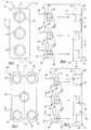
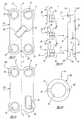
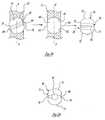
FIGURE 1 is a top view of a bone fixation plate in accordance with the present invention;FIGURE 2 is an exploded side view, partially in cross-section, of a bone fixation plate in accordance with the present invention;FIGURE 3 is an exploded side view, partially in cross-section, of an alternative embodiment of an insert in accordance with the present invention;FIGURE 4 is a representation of an upper cervical spine having a bone fixation plate assembly in accordance with one embodiment of the present invention affixed thereto;FIGURE 5 is a top view of another embodiment of the bone fixation plate in accordance with the present invention;FIGURE 6 is an exploded side view partially in cross-section, of an embodiment of the bone fixation plate assembly shown inFigure 5 ;FIGURE 7 is a top view of another embodiment of the bone fixation plate in accordance with the present invention;FIGURE 8 is an exploded side view of the embodiment of the bone fixation plate shown inFigure 7 ;FIGURE 9 is a top view of another embodiment of the bone fixation plate in accordance with the present invention;FIGURE 10 is an exploded side view of the embodiment of the bone fixation plate shown inFigure 9 ;FIGURE 11 is a top view of another embodiment of the bone fixation plate in accordance with the present invention;FIGURE 12 is an exploded side view of the embodiment of the bone fixation plate shown inFigure 11 ;FIGURE 13 is a top view of another embodiment of the bone fixation plate in accordance with the present invention;FIGURE 14 is an exploded side view of the embodiment of the bone fixation plate shown inFigure 13 ;FIGURE 15 is a top view of another embodiment of the bone fixation plate in accordance with the present invention;FIGURE 16 is a top view of an insert in accordance with the present invention;FIGURE 17 is a side view of a bone screw utilized with the bone fixation assembly of the present invention;FIGURE 18 is an exploded side view, partially in cross-section, of an alternative mechanism of fixation in accordance with the present invention;FIGURE 19 is an exploded side view partially in cross-section and fragmented, of an alternative insert in accordance with the present invention; andFIGURE 20 is an end on view of an alternative insert in accordance with the present invention taken along lines 20-20 ofFigure 19 .- A bone fixation plate assembly constructed in accordance with the present invention is generally shown at 10 in
Figure 1 and in an exploded view inFigure 2 . - More generally, referring additionally to
Figure 4 , the bonefixation plate assembly 10 includes a substantially flat elongatedbone fixation plate 12 having a longitudinal axis (A) defined by afirst end 14 and asecond end 16. The length of the elongated bone fixation plate along the axis (A) should be sufficient enough to span betweenadjacent vertebrae 18. The elongatedbone fixation plate 12 also includes anupper surface 20 and alower surface 22 thelower surface 22 is adapted to engage thevertebrae 18. Apertures 24 can be disposed at eachend bone fixation plate 12. Amechanism 26 for allowing movement betweenadjacent vertebrae 18 while maintaining engagement of thebone fixation plate 12 with thevertebrae 18 is disposed in the bonefixation plate assembly 10.- More specifically, referring to
Figures 2 and 4 , themechanism 26 for allowing movement between theadjacent vertebrae 18 includes aninsert 28 disposed in at least one of theapertures 24 for receiving and retaining ascrew 40 therein. Theinsert 28 is rotatably fixed within theaperture 24 and can freely rotate therein. When the screw is inserted and tightened within theinsert 28, both thescrew 40 and theinsert 28 can rotate axially about the longitudinal axis of thescrew 40 while simultaneously preventing axial movement of thescrew 40 with relation to thebone fixation plate 12. - Additionally, the
insert 28 can be fixed within theaperture 24 with a degree of side to side play between theinsert 28 and thebone fixation plate 12 such that not only can the insert 28 rotate freely within theaperture 28, theinsert 28 can move from side to side or wobble within theaperture 24. By wobbling or rocking within theaperture 24, theinsert 28 allows for longitudinal movement of the underlying bones with respect to bore fixation plate (12) to be tolerated and absorbed by thebone fixation assembly 10. That is great movement and shifting of the underlying bones to which theassembly 10 is affixed to can be acceptably tolerated without failure of theassembly 10 or damage to surrounding tissues or structures. - The ability of the
insert 28 to rotate and/or wobble within the bone fixation plate is important as it is well understood according to Wolff's Law that bones grow along lines of stress. Therefore, in order for fusion to occur between two or more vertebral bodies, a graft placed between the vertebral bodies must be loaded or stressed for solid bone fusion to occur. The biology of bones makes the fusion process very dynamic. Graft material slowly resorbs as osteoclasts remove bone and osteoblasts replace bone with new living bone. With a rigid plate construct, where the screws hold the vertebral bodies at a fixed apart distance, any resorption of the bone graft reduces or eliminates the compression or stress forces on the graft. Accordingly, these rigid plate constructs can induce or cause a condition known as psuedoarthrosis. Therefore, in accordance with the present invention, it is important to maintain the graft under load and/or stress while allowing the plate to compensate for the bone dynamics. This can be accomplished utilizing themechanism 26 as described herein. - The
insert 28 is mounted within theaperture 24. Preferably, theaperture 24 is a circular bore. The bore can include at least one internalannular recess 13 disposed in either theupper surface 20, thelower surface 22, or both surfaces of thebone fixation plate 12 and apassageway 15 therebetween defined by the bore of theaperture 24. Theinsert 28 is in mating engagement with the internal annular recess or recesses 13 to lock theinsert 28 within thebone fixation plate 12. - The
insert 28 includes alocking mechanism 42 for locking thescrew 40 within thebone fixation plate 12. Preferably, thelocking mechanism 42 includes threads disposed within anaxial bore 33 which are adapted engage and retain thescrew 40 therein. Referring toFigure 2 , the insert includes anannular recess 30 defined at one end by a circumferential threadedscrew receiving flange 32 and at the other end by a frustoconical or wedge-shapedinsert flange 34. Theaxial bore 33 extends from the circumferential threadedscrew receiving flange 32 to the end of thefrustoconical insert flange 34. Theannular recess 30 and thefrustoconical insert portion 34 can be biased outwardly and can include atransverse slot 36 disposed therein which bisects both theannular recess 30 and theinsert flange 34. - During insertion of the
insert 28 within theaperture 24, both thefrustoconical insert portion 34 and theannular recess 30 are compressed as thefrustoconical insert portion 34 engages the walls of the annularinternal recess 13 of thebone fixation plate 12. That is, the frustoconical shape of theinsert portion 34 acts as a ramping surface which, when in contact with the annularinternal recess 13 gradually compresses theinsert portion 34 and theannular recess 30 by compressing or closing thetransverse slot 36. When theinsert portion 34 andannular recess 30 are compressed, they are able to pass through thechannel 15 of theaperture 24 until they reach the internal recess disposed in thelower surface 22 of the bone fixation plate or side opposite which theinsert 28 was inserted. Once thefrustoconical insert portion 34 exits from thechannel 15 of theaperture 24, the outward biasing force causes thefrustoconical insert portion 34 to expand and engage the walls of theinternal recess 13 to lock theinsert 28 within thebone fixation plate 12. Since the diameter of the uncompressedfrustoconical insert portion 34 is larger than the diameter of the bore of theaperture 24, the frustoconical or wedge shaped portion of theinsert portion 34 prevents the withdrawal of theinsert 28 from theaperture 24. Thus, theinsert 28 is locked into thebone fixation plate 12. - The diameter of the
annular recess 30 can also be smaller than the diameter of the bore oraperture 24 so that theinsert 28 is free to rotate within theaperture 24. - Alternatively, an insert 28' can be constructed in multiple parts as shown in
Figure 3 . The insert 28' can include an axial bore 33' having threads 42' disposed therein. The insert 28' also can include a circumferential threaded screw receiving portion 32' and an annular recess 30'. A retainingmember 29 which includes structure for engaging a portion of the annular recess 30' can be provided to retain the insert 28' within therecess 13 of thebone fixation plate 12. The retainingmember 29 can be affixed to the annular recess 30' by means such as compression fitting, threaded engagement, or by other means well known to those skilled in the art. - Referring to
Figure 4 , a bonefixation plate assembly 10 is shown affixed to twoadjacent vertebrae 18. Thebone fixation plate 12 is mounted to theadjacent vertebrae 18 by way of a number of bone engaging screws 40. Thescrew 40 is in threaded engagement with theinsert 28 as is shown in phantom at 42. - Numerous embodiments of the invention are contemplated. For example, referring to
Figures 5 and 6 , a bone fixation assembly designated as 10 is shown. In this embodiment, thebone fixation plate 12 is substantially flat and includes twoapertures 24 disposed at theend bone fixation plate 12 and also includes at least one additional aperture to 24' disposed between theends bone fixation plate 12. In this embodiment, theaperture 24' disposed between theends bone fixation plate 12 is equidistantly disposed between theends bone fixation plate 12 along the longitudinal axis (A). However, theaperture 24' disposed between theends bone fixation plate 12 can be disposed at any point in between theends bone fixation plate 12. Additionally, theadditional aperture 24' can be disposed adjacent to the longitudinal axis (A). The placement of theadditional apertures 24' depends upon the application to which theassembly 10 is to be applied. - Referring to
Figures 7 and 8 , an additional embodiment of a substantially flat bonefixation plate assembly 10 is provided wherein fiveapertures apertures 24 are disposed at eachend bone fixation plate 12. Anadditional aperture 24' is equidistantly disposed between theends bone fixation plate 12. - As shown in
Figures 9 and 10 , a further embodiment of the assembly is shown. This embodiment is similar to the embodiment shown inFigures 7 and 8 , however, the bone fixation plate assembly is arcuately shaped or curved transverse to the longitudinal access (A) to conform the bone fixation plate 212' to the curvature of the vertebrae. Utilization of a curved or formed fixation plate 12', 212' can be incorporated into any embodiment of the bone fixation assembly in accordance with the present invention and is not limited by the specific embodiments disclosed herein which are provided as examples of the possible designs which can be utilized with the present invention. - Referring to
Figures 11 and 12 , a further embodiment of the bone fixation plate assembly of the present invention is shown at 210'. This embodiment includes a curved, elongated, a substantially bone fixation plate 212' includingrectangular slot 44 having arecess 45 disposed therein. Theelongated slot 44 is disposed substantially parallel to the longitudinal axis (A) of the bone fixation plate 212''. - The substantially
rectangular slot 44 allows theinsert 28 to be adjustably positioned at various locations within theslot 44. By being adjustable, the assembly 210' is able to be utilized in a greater number of locations and applications. Additionally theinsert 28 disposed in theslot 44 can be allowed to slide freely within theslot 44 to accommodate movement of the underlying bone or bones. - Referring to
Figures 13 and 14 , afurther embodiment 210 is shown having as an elongated slot 44'. The elongated slot 44' is disposed at a substantially acute angle with respect to the longitudinal axis (A) of the substantially flatbone fixation plate 212. - In a further embodiment shown in
Figure 15 , an elongated slot 44'' is shown disposed at oneend 16 of thebone fixation plate 212 and parallel to the longitudinal axis (A). - In all of the embodiments shown in
Figures 11 through 15 , theelongated slot 44, 44', 44'' accepts at least oneinsert 28, 28' therein. Theinserts 28, 28' can be affixed within therecess 45 in a manner similar to that discussed above. Theelongated slot 44, 44', 44'' allows for a substantial margin for adjustment and proper location of thescrew 40 and thebone fixation plate inserts 28, 28' can be made to slide freely within theslot 44, 44', 44'', - The spacing or orientation of the
apertures slots 44, 44', 44'', and theinserts 28, 28' within the bonefixation plate assembly screws 40 disposed in the various combinations ofapertures slots 44, 44', 44'' described above. That is, the bonefixation plate assembly screw 40 can be distributed in a desired manner, including load shifting after theassembly assembly - Referring to
Figure 6 , thebone fixation assembly 10 is shown including abone engagement mechanism 46 disposed on thelower surface 22 of thebone fixation plate 12 for enhancing the engagement of thebone fixation plate 12 to the vertebrae. Preferably, thebone engagement mechanism 46 includes a texturized surface disposed on substantially all of thelower surface 22 of thebone fixation plate 12. In other embodiments, the texturized surface can be disposed on only a portion of thelower surface 22 as is shown inFigure 6 . - The texturized surface can include etched, roughened, grooved, knurled, or like contouring of the
lower surface 22 of thebone fixation plate 12 as is well known in the art. - Referring to
Figure 16 , thescrew receiving portion 32 of theinsert 28 is shown in greater detail. At least tworectangular recesses 38 are disposed therein. Therecesses 38 are adapted to receive a device, such as a screwdriver or similar tool, to prevent rotation of theinsert 28 within theaperture 24 during the insertion and tightening of thescrew 40 disposed therein to the underlying bone. The location and configuration of therecesses 38 within thescrew receiving portion 32 of theinsert 28 can be varied according to a desired or specific tool to be utilized for the purpose of preventing rotation of the insert means 28. In operation, the tool or device would be placed in mating engagement with therecesses 38 thereby providing leverage to withstand the rotational or torque forces applied to theinsert 28 via thethreads 42 disposed in thebore 33 of theinsert 28 as transmitted thereto by thescrew 40. - The
screws 40 utilized for securing the bonefixation plate assembly screws 40 utilized in the present invention are of the type illustrated inFigure 17 . Thescrew 40 typically comprises a screw with a shaft having ahead 50 and atip 52. Theshaft 48 is threaded and includes two differently threadedportions 54, 56. Portion 54 is threaded to threadingly engage with thethreads 42 of theinsert 28. The threadedportion 56 is threaded to specifically engage bone. An example of a screw which can be used with the bonefixation plate assembly 5,601,553 to Trebing et al. Alternatively, thescrew threads 54, 56 can utilize the same thread for both portions. - In an alternative mechanism for fixation of the bone
fixation plate assembly 10 to thevertebrae 18 as shown inFigure 18 . aheadless screw 40 can first be driven into and affixed within the bone. Thebone fixation plate bone fixation assembly insert 28, 28' disposed therein would then be disposed over the portion of thescrew 40 protruding from the bone and would be fixed to thebone fixation plate screw receiving portion 32 of theinsert 28, 28' with the threads of the portion of thescrew 40 protruding from the bone. - Referring to
Figures 19 and 20 , an alternative embodiment for both analternative insert 70 andaperture 60 is shown. Theaperture 60 which can be disposed in anyplate bone fixation plate aperture 60. Into theaperture 60, aninsert 70 including substantiallyhemispherical portions 72 disposed at the ends of theinsert 70 and substantiallystraight side portions 75 can be disposed. An axial threaded bore 76 in theinsert 70 is provided to acceptbone screws 40 therein. Atransverse slot 78 is provided in theinsert 70 to allow theinsert 70 to be contracted or to be compressed to facilitate its insertion within theaperture 60. - Referring specifically to
Figure 20 , the biasing mechanism of theinsert 70 is shown in greater detail. Thetransverse slot 78 extends through theinsert 70 substantially bisecting theinsert 70. A portion 80 of theinsert 70 defines a terminal margin of theslot 78. This portion 80 of theinsert 70 allows theinsert 70 to be compressed for insertion into theaperture 60. That is, the portion 80 acts as a hinge or spring to allow theinsert 70 to compress and to expand. Theinsert 70 can be biased outwardly as described above for theinsert 28. Afterinsert 70 is disposed within theaperture 60, theinsert 70 freely rotates within thebore 76 and also, theinsert 70 can be moved or positioned to any angle such that thebore 76 is angled with respect to the axis (A) of theplate insert 70 to be angled with respect to the longitudinal axis (A) of theplate screws 40 to be inserted at angles with respect to the longitudinal axis (A) of theplate - The advantage of the
insert 70 being able to rotate in more than one plane is that it allows a surgeon to place the screw at any angle in necessary order to adapt thebone fixation assembly positionable insert 70 would allow easier correction of the deformity while still allowing for the utilization of thelow profile plate - The bone
fixation plate assembly
Claims (24)
- A bone fixation plate assembly (10, 210, 210') for fixation of the spine comprising:a fixation plate (12, 212, 212') including first and second ends (14, 16) and at least one aperture (24, 24', 60) disposed at each of said first and second ends (14, 16) thereof; anda mechanism (26) for allowing movement between adjacent vertebrae (18) while simultaneously maintaining engagement of said bone fixation plate (12) with the vertebrae (18)said mechanism (26) including an insert (28, 28', 70) disposed in at least one of said apertures (24, 24', 60) for receiving and retaining a screw (40) therein, said insert comprising an axial throughbore (33);wherein the axial throughbore (33) of the insert is adapted to engage a portion of the screw (40) and provide a locked condition wherein the screw is locked relative to said insert and is in non-engagement with said plate, and wherein the screw (40) and insert (28,28',70) form an assembly which is free to rotate and move from side to side or wobble relative to said plate (12, 212, 212').
- A bone fixation plate assembly (10, 210, 210') according to claim 1, wherein said fixation plate (12, 212, 212') includes a longitudinal axis (A) defined by the first and second ends (14, 16) and the length along said axis (A) is sufficient to span between the adjacent vertebrae (18), said bone fixation plate (12, 212, 212') including an upper (20) and a lower (22) surface, said lower surface (22) adapted to engage the vertebrae (18).
- A bone fixation plate assembly (10, 210, 210') according to claim 1, wherein said at least one aperture (24,24') is a bore.
- A bone fixation plate assembly (10,210,210') according to claim 3, wherein said bore includes at least one internal recess (13) disposed in either an upper surface (20), a lower surface (22), or both upper and lower surfaces (20,22) of said fixation plate (12,212,212').
- A bone fixation plate assembly (10,210,210') according to claim 4, wherein said insert (28,28') is in mating engagement with said internal recess (13) to lock said insert (28,28') within said fixation plate (12,212,212').
- A bone fixation plate assembly (10,210,210') according to claim 1 or 2, wherein said insert (28,28',70) freely rotates within said aperture (24,24',60).
- A bone fixation plate assembly (10,210,210') according to claim 2, wherein said fixation plate (12,212,212') includes said at least one aperture (24') disposed between said ends (14,16) of said fixation plate (12,212,212').
- A bone fixation plate assembly (10,210,210') according to claim 7, wherein said at least one aperture (24') disposed between the ends (14,16) of said fixation plate (12,212,212') is disposed along the longitudinal axis (A) of said fixation plate (12,212,212').
- A bone fixation plate assembly (10,210,210') according to claim 2, wherein said at least one aperture (24,24') includes at least one elongated slot (44,44',44'') having a recess (45) disposed in said fixation plate (12,212,212').
- A bone fixation plate assembly (10,210,210') according to claim 9, wherein said elongated slot (44,44') is disposed substantially parallel to the longitudinal axis (A) of said fixation plate (12,212,212').
- A bone fixation plate assembly (10,210,210') according to claim 9, wherein said elongated slot (44') is disposed at a substantially acute angle with respect to said longitudinal axis (A) of said fixation plate (12,212,212').
- A bone fixation plate assembly (10) according to claim 10, wherein said elongated slot (44,44') is disposed at one end (14,16) of said fixation plate (12,212,212').
- A bone fixation plate assembly (10,210,210') according to claim 1, wherein said fixation plate (12,212,212') is curved transverse to said longitudinal axis (A) to conform said fixation plate (12,212,212') to the curvature of the vertebrae (18).
- A bone fixation plate assembly (10,210,210') according to claim 2, wherein said lower surface (22) includes bone engagement means (46) for enhancing the engagement of said fixation plate (12,212,212') to the vertebrae (18).
- A bone fixation plate assembly (10,210,210') according to claim 14, wherein said bone engagement means (46) includes a texturized surface disposed on substantially all of said lower surface (22) of said fixation plate (12,212,212').
- A bone fixation plate assembly (10,210,210') according to claim 15, wherein said texturized surface is disposed on a portion of said lower surface (22).
- A bone fixation plate assembly (10,210,210') according to claim 1 or 2, wherein said insert (28) includes an annular recess (30) defined at one end by a circumferential threaded screw receiving portion (32) and at the other end by a frustoconical insert portion (34), said annular recess (30) and said frustoconical insert portion (34) being biased outwardly and include a transverse slot (36) disposed therein whereby upon insertion of said insert (28) into said aperture (24,24'), said annular recess (30) and said frustoconical insert portion (34) deflect inwardly to allow said annular recess (30) and said frustoconical insert portion (34) to pass through said fixation plate (12,212,212') and then deflect outwardly to lock said insert (28) into said bone fixation plate (12, 212, 212').
- A bone fixation plate assembly (10,210,210') according to claim 17, wherein said screw receiving portion (32) of said insert (28) includes at least two recesses (38) adapted to receive a device to prevent rotation of said insert (28) within said aperture (24,24') during insertion and tightening of the screw (40) disposed therein.
- A bone fixation plate assembly (10,210,210') according to claim 1, wherein the said insert (70) also including means for allowing angulation of the screw (40) with respect to the bone fixation plate (12,212,212').
- A bone fixation plate assembly (10,210,210') according to claim 19, wherein said at least one aperture (60) is defined by two substantially hemispherical ends (62) spaced apart by two substantially straight sides (64) extending therebetween.
- A bone fixation plate assembly (10,210,210') according to claim 19, wherein said angulation means of said insert (70) includes two substantially hemispherical portions (72) spaced apart by two substantially straight portions (75) extending therebetween.
- A bone fixation plate assembly (10,210,210') according to claim 21, wherein said angulation means allows said insert (70) to both freely rotate within said aperture (60) and to be adjusted to any angle with respect to said bone fixation plate (12,212,212').
- A bone fixation plate assembly (10,210,210') according to claim 19, wherein said insert (70) includes locking means for locking the screw (40) within said fixation plate (12,212,212').
- A bone fixation plate assembly (10,210,210') according to claim 23, wherein said locking means includes a threaded bore (76) adapted to retain the screw (40) therein.
Applications Claiming Priority (2)
| Application Number | Priority Date | Filing Date | Title |
|---|---|---|---|
| US08/854,021US6017345A (en) | 1997-05-09 | 1997-05-09 | Spinal fixation plate |
| US854021 | 1997-05-09 |
Publications (2)
| Publication Number | Publication Date |
|---|---|
| EP0897697A1 EP0897697A1 (en) | 1999-02-24 |
| EP0897697B1true EP0897697B1 (en) | 2009-08-26 |
Family
ID=25317525
Family Applications (1)
| Application Number | Title | Priority Date | Filing Date |
|---|---|---|---|
| EP98201465AExpired - LifetimeEP0897697B1 (en) | 1997-05-09 | 1998-05-08 | Spinal fixation plate |
Country Status (6)
| Country | Link |
|---|---|
| US (2) | US6017345A (en) |
| EP (1) | EP0897697B1 (en) |
| JP (3) | JP4488539B2 (en) |
| CA (1) | CA2237240C (en) |
| DE (1) | DE69841087D1 (en) |
| ES (1) | ES2331938T3 (en) |
Cited By (7)
| Publication number | Priority date | Publication date | Assignee | Title |
|---|---|---|---|---|
| US7776047B2 (en) | 2003-04-09 | 2010-08-17 | Depuy Spine, Inc. | Guide for spinal tools, implants, and devices |
| US7909848B2 (en) | 2003-06-27 | 2011-03-22 | Depuy Spine, Inc. | Tissue retractor and guide device |
| US7909829B2 (en) | 2003-06-27 | 2011-03-22 | Depuy Spine, Inc. | Tissue retractor and drill guide |
| US7935123B2 (en) | 2003-04-09 | 2011-05-03 | Depuy Acromed, Inc. | Drill guide with alignment feature |
| US8361126B2 (en) | 2007-07-03 | 2013-01-29 | Pioneer Surgical Technology, Inc. | Bone plate system |
| US8623019B2 (en) | 2007-07-03 | 2014-01-07 | Pioneer Surgical Technology, Inc. | Bone plate system |
| US8900277B2 (en) | 2004-02-26 | 2014-12-02 | Pioneer Surgical Technology, Inc. | Bone plate system |
Families Citing this family (239)
| Publication number | Priority date | Publication date | Assignee | Title |
|---|---|---|---|---|
| US6306170B2 (en)* | 1997-04-25 | 2001-10-23 | Tegementa, L.L.C. | Threaded fusion cage anchoring device and method |
| US6454769B2 (en)* | 1997-08-04 | 2002-09-24 | Spinal Concepts, Inc. | System and method for stabilizing the human spine with a bone plate |
| US20040220571A1 (en)* | 1998-04-30 | 2004-11-04 | Richard Assaker | Bone plate assembly |
| FR2778088B1 (en)* | 1998-04-30 | 2000-09-08 | Materiel Orthopedique En Abreg | ANTERIOR IMPLANT, PARTICULARLY FOR THE CERVICAL RACHIS |
| US6533786B1 (en)* | 1999-10-13 | 2003-03-18 | Sdgi Holdings, Inc. | Anterior cervical plating system |
| FR2784571B1 (en)* | 1998-10-19 | 2001-02-02 | Scient X | ANTERIOR OSTEOSYNTHESIS PLATE FOR LUMBAR OR LUMBAR / SACRED VERTEBRES AND INSTRUMENT FOR POSITIONING SUCH A PLATE |
| WO2000059388A1 (en)* | 1999-04-05 | 2000-10-12 | Surgical Dynamics, Inc. | Artificial spinal ligament |
| US6342055B1 (en)* | 1999-04-29 | 2002-01-29 | Theken Surgical Llc | Bone fixation system |
| EP1370183B1 (en)* | 1999-07-07 | 2014-02-19 | Children's Hospital Medical Center | Spinal correction system |
| US6261291B1 (en)* | 1999-07-08 | 2001-07-17 | David J. Talaber | Orthopedic implant assembly |
| US20050256582A1 (en)* | 1999-10-08 | 2005-11-17 | Ferree Bret A | Spinal implants, including devices that reduce pressure on the annulus fibrosis |
| US6224602B1 (en) | 1999-10-11 | 2001-05-01 | Interpore Cross International | Bone stabilization plate with a secured-locking mechanism for cervical fixation |
| US6692503B2 (en) | 1999-10-13 | 2004-02-17 | Sdgi Holdings, Inc | System and method for securing a plate to the spinal column |
| ES2270888T3 (en) | 1999-12-01 | 2007-04-16 | Henry Graf | INTERVERTEBRAL STABILIZATION DEVICE. |
| US6331179B1 (en)* | 2000-01-06 | 2001-12-18 | Spinal Concepts, Inc. | System and method for stabilizing the human spine with a bone plate |
| US6235033B1 (en) | 2000-04-19 | 2001-05-22 | Synthes (Usa) | Bone fixation assembly |
| US6524315B1 (en)* | 2000-08-08 | 2003-02-25 | Depuy Acromed, Inc. | Orthopaedic rod/plate locking mechanism |
| US6776781B1 (en) | 2000-09-28 | 2004-08-17 | Farihan Renno | Spinal-column buttress plate assembly and method for attachment |
| US6740088B1 (en)* | 2000-10-25 | 2004-05-25 | Sdgi Holdings, Inc. | Anterior lumbar plate and method |
| US6503250B2 (en)* | 2000-11-28 | 2003-01-07 | Kamaljit S. Paul | Bone support assembly |
| US20050010227A1 (en)* | 2000-11-28 | 2005-01-13 | Paul Kamaljit S. | Bone support plate assembly |
| US6413259B1 (en) | 2000-12-14 | 2002-07-02 | Blackstone Medical, Inc | Bone plate assembly including a screw retaining member |
| FR2823096B1 (en)* | 2001-04-06 | 2004-03-19 | Materiel Orthopedique En Abreg | PLATE FOR LTE AND LTE VERTEBRATE OSTEOSYNTHESIS DEVICE, OSTEOSYNTHESIS DEVICE INCLUDING SUCH A PLATE, AND INSTRUMENT FOR LAYING SUCH A PLATE |
| US20050049594A1 (en)* | 2001-04-20 | 2005-03-03 | Wack Michael A. | Dual locking plate and associated method |
| US20020156474A1 (en)* | 2001-04-20 | 2002-10-24 | Michael Wack | Polyaxial locking plate |
| US7717945B2 (en) | 2002-07-22 | 2010-05-18 | Acumed Llc | Orthopedic systems |
| US7326212B2 (en) | 2002-11-19 | 2008-02-05 | Acumed Llc | Bone plates with reference marks |
| US7537604B2 (en) | 2002-11-19 | 2009-05-26 | Acumed Llc | Bone plates with slots |
| US20050240187A1 (en) | 2004-04-22 | 2005-10-27 | Huebner Randall J | Expanded fixation of bones |
| US6746451B2 (en)* | 2001-06-01 | 2004-06-08 | Lance M. Middleton | Tissue cavitation device and method |
| FR2827499B1 (en)* | 2001-07-20 | 2004-05-07 | Henry Graf | INTERVERTEBRAL LINK DEVICE |
| US6793657B2 (en) | 2001-09-10 | 2004-09-21 | Solco Biomedical Co., Ltd. | Spine fixing apparatus |
| AU2002349962B2 (en)* | 2001-10-19 | 2006-04-06 | Baylor College Of Medicine | Bone compression devices and systems and methods of contouring and using same |
| DE10152094C2 (en)* | 2001-10-23 | 2003-11-27 | Biedermann Motech Gmbh | Bone fixation device |
| US6679883B2 (en) | 2001-10-31 | 2004-01-20 | Ortho Development Corporation | Cervical plate for stabilizing the human spine |
| US7766947B2 (en)* | 2001-10-31 | 2010-08-03 | Ortho Development Corporation | Cervical plate for stabilizing the human spine |
| US7008426B2 (en)* | 2001-12-14 | 2006-03-07 | Paul Kamaljit S | Bone treatment plate assembly |
| US7070599B2 (en)* | 2002-07-24 | 2006-07-04 | Paul Kamaljit S | Bone support assembly |
| US6755833B1 (en)* | 2001-12-14 | 2004-06-29 | Kamaljit S. Paul | Bone support assembly |
| CA2471843C (en)* | 2001-12-24 | 2011-04-12 | Synthes (U.S.A.) | Device for osteosynthesis |
| US7303564B2 (en) | 2002-02-01 | 2007-12-04 | Spinal Concepts, Inc. | Spinal plate extender system and method |
| US7322983B2 (en)* | 2002-02-12 | 2008-01-29 | Ebi, L.P. | Self-locking bone screw and implant |
| AR038680A1 (en) | 2002-02-19 | 2005-01-26 | Synthes Ag | INTERVERTEBRAL IMPLANT |
| US6695846B2 (en) | 2002-03-12 | 2004-02-24 | Spinal Innovations, Llc | Bone plate and screw retaining mechanism |
| US20030187443A1 (en)* | 2002-03-27 | 2003-10-02 | Carl Lauryssen | Anterior bone plate system and method of use |
| US7001389B1 (en) | 2002-07-05 | 2006-02-21 | Navarro Richard R | Fixed and variable locking fixation assembly |
| US6989012B2 (en)* | 2002-07-16 | 2006-01-24 | Sdgi Holdings, Inc. | Plating system for stabilizing a bony segment |
| CN1309352C (en) | 2002-07-22 | 2007-04-11 | 精密医疗责任有限公司 | Bone fusion system |
| US7862597B2 (en)* | 2002-08-22 | 2011-01-04 | Warsaw Orthopedic, Inc. | System for stabilizing a portion of the spine |
| US7179260B2 (en)* | 2003-09-29 | 2007-02-20 | Smith & Nephew, Inc. | Bone plates and bone plate assemblies |
| CA2504215A1 (en)* | 2002-10-28 | 2004-05-13 | Blackstone Medical, Inc. | Bone plate assembly provided with screw locking mechanisms |
| US7682392B2 (en)* | 2002-10-30 | 2010-03-23 | Depuy Spine, Inc. | Regenerative implants for stabilizing the spine and devices for attachment of said implants |
| AU2003294414B2 (en) | 2002-11-19 | 2009-03-12 | Acumed Llc | Deformable bone plates |
| AU2003294342A1 (en) | 2002-11-19 | 2004-06-15 | Acumed Llc | Guide system for bone-repair devices |
| US7811312B2 (en)* | 2002-12-04 | 2010-10-12 | Morphographics, Lc | Bone alignment implant and method of use |
| US7914561B2 (en) | 2002-12-31 | 2011-03-29 | Depuy Spine, Inc. | Resilient bone plate and screw system allowing bi-directional assembly |
| US7048739B2 (en)* | 2002-12-31 | 2006-05-23 | Depuy Spine, Inc. | Bone plate and resilient screw system allowing bi-directional assembly |
| US7175624B2 (en)* | 2002-12-31 | 2007-02-13 | Depuy Spine, Inc. | Bone plate and screw system allowing bi-directional assembly |
| US7341591B2 (en)* | 2003-01-30 | 2008-03-11 | Depuy Spine, Inc. | Anterior buttress staple |
| US8172885B2 (en) | 2003-02-05 | 2012-05-08 | Pioneer Surgical Technology, Inc. | Bone plate system |
| CA2515247C (en) | 2003-02-06 | 2010-10-05 | Synthes (U.S.A.) | Intervertebral implant |
| US7278997B1 (en) | 2003-03-07 | 2007-10-09 | Theken Spine, Llc | Instrument guide and implant holder |
| DE602004001398T2 (en)* | 2003-03-20 | 2007-06-14 | Stryker Trauma S.A. | BONE CONNECTION DEVICE |
| US20040204712A1 (en)* | 2003-04-09 | 2004-10-14 | Eric Kolb | Bone fixation plates |
| US7416553B2 (en)* | 2003-04-09 | 2008-08-26 | Depuy Acromed, Inc. | Drill guide and plate inserter |
| DE10317871B3 (en)* | 2003-04-17 | 2004-11-11 | Stryker Leibinger Gmbh & Co. Kg | Osteosynthesis device |
| US7169150B2 (en)* | 2003-04-25 | 2007-01-30 | Warsaw Orthopedic, Inc. | Non-metallic orthopedic plate |
| US7309340B2 (en) | 2003-06-20 | 2007-12-18 | Medicinelodge, Inc. | Method and apparatus for bone plating |
| WO2004112587A2 (en) | 2003-06-20 | 2004-12-29 | Acumed Llc | Bone plates with intraoperatively tapped apertures |
| US7635365B2 (en) | 2003-08-28 | 2009-12-22 | Ellis Thomas J | Bone plates |
| US7909860B2 (en)* | 2003-09-03 | 2011-03-22 | Synthes Usa, Llc | Bone plate with captive clips |
| US7857839B2 (en)* | 2003-09-03 | 2010-12-28 | Synthes Usa, Llc | Bone plate with captive clips |
| US20050049595A1 (en)* | 2003-09-03 | 2005-03-03 | Suh Sean S. | Track-plate carriage system |
| US20050059970A1 (en)* | 2003-09-17 | 2005-03-17 | Eric Kolb | Bone fixation systems |
| US8105367B2 (en) | 2003-09-29 | 2012-01-31 | Smith & Nephew, Inc. | Bone plate and bone plate assemblies including polyaxial fasteners |
| FR2861980B1 (en)* | 2003-11-07 | 2006-09-01 | Euros Sa | IMPLANT SYSTEM COMPRISING AN IMPLANT AND IMPLANT MOUNTING MEANS HAVING A SCREW-IN ANCHOR SCREW IN A CLIPPING BLOCK MEMBER IN THE IMPLANT |
| US8182518B2 (en)* | 2003-12-22 | 2012-05-22 | Life Spine, Inc. | Static and dynamic cervical plates and cervical plate constructs |
| US7806914B2 (en)* | 2003-12-31 | 2010-10-05 | Spine Wave, Inc. | Dynamic spinal stabilization system |
| US20050143737A1 (en)* | 2003-12-31 | 2005-06-30 | John Pafford | Dynamic spinal stabilization system |
| US7678137B2 (en) | 2004-01-13 | 2010-03-16 | Life Spine, Inc. | Pedicle screw constructs for spine fixation systems |
| US20050165487A1 (en)* | 2004-01-28 | 2005-07-28 | Muhanna Nabil L. | Artificial intervertebral disc |
| US20080027440A1 (en)* | 2004-01-30 | 2008-01-31 | Dsm Ip Assets B.V. | Fixing Device For Clamping The Ends Of A Surgical Cable Used For Fixing Bone Parts |
| US8002809B2 (en)* | 2004-02-10 | 2011-08-23 | Atlas Spine, Inc. | Dynamic cervical plate |
| US8328854B2 (en)* | 2004-02-10 | 2012-12-11 | Atlas Spine, Inc. | Cervical plate ratchet pedicle screws |
| US20050177160A1 (en)* | 2004-02-10 | 2005-08-11 | Baynham Bret O. | Dynamic cervical plate |
| US7815666B2 (en)* | 2004-02-10 | 2010-10-19 | Atlas Spine, Inc. | Dynamic cervical plate |
| US7740649B2 (en) | 2004-02-26 | 2010-06-22 | Pioneer Surgical Technology, Inc. | Bone plate system and methods |
| US20050209593A1 (en) | 2004-03-06 | 2005-09-22 | Depuy Spine, Inc. | Flexible anterior cervical plate |
| WO2005102193A2 (en) | 2004-04-19 | 2005-11-03 | Acumed, Llc | Placement of fasteners into bone |
| US8241337B2 (en)* | 2004-05-25 | 2012-08-14 | Brockmeyer Douglas L | Occipitocervical plate |
| US7942912B2 (en)* | 2004-05-25 | 2011-05-17 | University Of Utah Research Foundation | Occipitocervical plate |
| US8142462B2 (en) | 2004-05-28 | 2012-03-27 | Cavitech, Llc | Instruments and methods for reducing and stabilizing bone fractures |
| US7938848B2 (en)* | 2004-06-09 | 2011-05-10 | Life Spine, Inc. | Spinal fixation system |
| US7744635B2 (en)* | 2004-06-09 | 2010-06-29 | Spinal Generations, Llc | Spinal fixation system |
| US7727266B2 (en) | 2004-06-17 | 2010-06-01 | Warsaw Orthopedic, Inc. | Method and apparatus for retaining screws in a plate |
| US7854752B2 (en) | 2004-08-09 | 2010-12-21 | Theken Spine, Llc | System and method for dynamic skeletal stabilization |
| US20060036250A1 (en)* | 2004-08-12 | 2006-02-16 | Lange Eric C | Antero-lateral plating systems for spinal stabilization |
| US20060052784A1 (en)* | 2004-08-17 | 2006-03-09 | Zimmer Spine, Inc. | Polyaxial device for spine stabilization during osteosynthesis |
| US9615866B1 (en) | 2004-10-18 | 2017-04-11 | Nuvasive, Inc. | Surgical fixation system and related methods |
| US20060106387A1 (en)* | 2004-11-16 | 2006-05-18 | Depuy Spine, Inc. | Spinal plate system and method of use |
| WO2006058221A2 (en) | 2004-11-24 | 2006-06-01 | Abdou Samy M | Devices and methods for inter-vertebral orthopedic device placement |
| US7799062B2 (en)* | 2004-11-30 | 2010-09-21 | Stryker Trauma S.A. | Self-guiding threaded fastener |
| US7931678B2 (en) | 2004-12-08 | 2011-04-26 | Depuy Spine, Inc. | Hybrid spinal plates |
| US7736380B2 (en)* | 2004-12-21 | 2010-06-15 | Rhausler, Inc. | Cervical plate system |
| US20060195085A1 (en)* | 2005-02-01 | 2006-08-31 | Inion Ltd. | System and method for stabilizing spine |
| US20060195089A1 (en)* | 2005-02-03 | 2006-08-31 | Lehuec Jean-Charles | Spinal plating and intervertebral support systems and methods |
| EP1693013A1 (en)* | 2005-02-22 | 2006-08-23 | Kyon | Plate and screws for treatment of bone fractures |
| US20060235403A1 (en)* | 2005-03-17 | 2006-10-19 | Jason Blain | Flanged interbody fusion device with locking plate |
| US7749257B2 (en)* | 2005-04-12 | 2010-07-06 | Robert J. Medoff | Bearing plate for use in fracture fixation having a spherical bearing hole with yielding expandability |
| US7678113B2 (en)* | 2005-04-19 | 2010-03-16 | Warsaw Orthopedic, Inc. | Antero-lateral plating systems and methods for spinal stabilization |
| US7674296B2 (en) | 2005-04-21 | 2010-03-09 | Globus Medical, Inc. | Expandable vertebral prosthesis |
| US8070749B2 (en) | 2005-05-12 | 2011-12-06 | Stern Joseph D | Revisable anterior cervical plating system |
| WO2006124273A2 (en)* | 2005-05-12 | 2006-11-23 | Stern Joseph D | Revisable anterior cervical plating system |
| WO2007011431A2 (en)* | 2005-07-18 | 2007-01-25 | Dong Myung Jeon | Bi-polar bone screw assembly |
| US8382807B2 (en) | 2005-07-25 | 2013-02-26 | Smith & Nephew, Inc. | Systems and methods for using polyaxial plates |
| CA2616798C (en) | 2005-07-25 | 2014-01-28 | Smith & Nephew, Inc. | Systems and methods for using polyaxial plates |
| US9072554B2 (en)* | 2005-09-21 | 2015-07-07 | Children's Hospital Medical Center | Orthopedic implant |
| US8262713B2 (en) | 2005-09-26 | 2012-09-11 | Depuy Spine, Inc. | Red light implant for treating osteoporosis |
| WO2007040553A1 (en)* | 2005-09-26 | 2007-04-12 | Dong Jeon | Hybrid jointed bone screw system |
| US7465313B2 (en)* | 2005-09-26 | 2008-12-16 | Depuy Spine, Inc. | Red light implant for treating degenerative disc disease |
| EP1956991A1 (en)* | 2005-11-15 | 2008-08-20 | Aoi Medical, Inc. | Inflatable device for restoring anatomy of fractured bone |
| US9119677B2 (en) | 2005-12-09 | 2015-09-01 | DePuy Synthes Products, Inc. | Spinal plate and drill guide |
| EP1971282A2 (en) | 2006-01-10 | 2008-09-24 | Life Spine, Inc. | Pedicle screw constructs and spinal rod attachment assemblies |
| US7473255B2 (en)* | 2006-02-08 | 2009-01-06 | Synthes (U.S.A.) | Transbuccal plate holding cannula |
| WO2007098188A2 (en)* | 2006-02-21 | 2007-08-30 | Life Spine, Inc. | Structure for joining and retaining multi-part orthopedic implants |
| EP1988855A2 (en) | 2006-02-27 | 2008-11-12 | Synthes GmbH | Intervertebral implant with fixation geometry |
| US8025681B2 (en)* | 2006-03-29 | 2011-09-27 | Theken Spine, Llc | Dynamic motion spinal stabilization system |
| US7951178B2 (en)* | 2006-04-03 | 2011-05-31 | Acumed Llc | Bone plates with hybrid apertures |
| WO2007114834A1 (en) | 2006-04-05 | 2007-10-11 | Dong Myung Jeon | Multi-axial, double locking bone screw assembly |
| WO2007123979A2 (en) | 2006-04-18 | 2007-11-01 | University Of South Florida | Cervical plate system |
| US8388660B1 (en) | 2006-08-01 | 2013-03-05 | Samy Abdou | Devices and methods for superior fixation of orthopedic devices onto the vertebral column |
| US8361130B2 (en) | 2006-10-06 | 2013-01-29 | Depuy Spine, Inc. | Bone screw fixation |
| US8066750B2 (en) | 2006-10-06 | 2011-11-29 | Warsaw Orthopedic, Inc | Port structures for non-rigid bone plates |
| FR2908627B1 (en)* | 2006-11-20 | 2009-07-03 | Tornier Sas | PROTHETIC OR OSTEOSYNTHESIS DEVICE WITH A SLICED OLIVE |
| WO2008091266A1 (en)* | 2006-12-07 | 2008-07-31 | Dong Myung Jeon | Spinal rod transverse connector system |
| KR100991204B1 (en)* | 2007-01-23 | 2010-11-01 | 주식회사 바이오스마트 | Spinos process for spine spacer |
| WO2008094572A2 (en)* | 2007-01-30 | 2008-08-07 | Dong Myung Jeon | Anterior cervical plating system |
| US8702762B2 (en) | 2007-03-27 | 2014-04-22 | Depuy Spine, Inc. | Passive screw locking mechanism |
| US20080269753A1 (en)* | 2007-04-26 | 2008-10-30 | Blue Fury Consulting, Llc | Dynamic cervical plate |
| US20090131952A1 (en)* | 2007-05-21 | 2009-05-21 | Brian Schumacher | Delivery system and method for inflatable devices |
| US7922767B2 (en)* | 2007-07-07 | 2011-04-12 | Jmea Corporation | Disk fusion implant |
| US20100160980A1 (en)* | 2007-07-26 | 2010-06-24 | Biotechni America Spine Group, Inc. | Spinal fixation assembly |
| US8496693B2 (en)* | 2007-10-16 | 2013-07-30 | Amendia Inc. | Bone screw retaining and removal system |
| JP2011502708A (en) | 2007-11-16 | 2011-01-27 | ジンテス ゲゼルシャフト ミット ベシュレンクテル ハフツング | Low profile intervertebral implant |
| US8303633B2 (en)* | 2007-12-13 | 2012-11-06 | K2M, Inc. | Dynamic anterior vertebral plate |
| US20090171395A1 (en)* | 2007-12-28 | 2009-07-02 | Jeon Dong M | Dynamic spinal rod system |
| US8282675B2 (en)* | 2008-01-25 | 2012-10-09 | Depuy Spine, Inc. | Anti-backout mechanism |
| US20090192548A1 (en)* | 2008-01-25 | 2009-07-30 | Jeon Dong M | Pedicle-laminar dynamic spinal stabilization device |
| US20090194206A1 (en)* | 2008-01-31 | 2009-08-06 | Jeon Dong M | Systems and methods for wrought nickel/titanium alloy flexible spinal rods |
| US20090210008A1 (en)* | 2008-02-20 | 2009-08-20 | Life Spine, Inc. | Modular spine plate with projection and socket interface |
| US8500783B2 (en)* | 2008-04-30 | 2013-08-06 | Atlas Spine, Inc. | Dynamic cervical plate with spacer |
| US8425514B2 (en)* | 2008-06-25 | 2013-04-23 | Westmark Medical, Llc. | Spinal fixation device |
| USD603962S1 (en) | 2008-07-03 | 2009-11-10 | Theken Spine, Llc | Cervical plate |
| USD603506S1 (en) | 2008-07-03 | 2009-11-03 | Theken Spine, Llc | Cervical plate |
| USD603963S1 (en) | 2008-07-03 | 2009-11-10 | Theken Spine, Llc | Cervical plate |
| USD603964S1 (en) | 2008-07-03 | 2009-11-10 | Theken Spine, Llc | Cervical plate |
| USD603510S1 (en) | 2008-07-03 | 2009-11-03 | Theken Spine, Llc | Cervical plate |
| USD603509S1 (en) | 2008-07-03 | 2009-11-03 | Theken Spine, Llc | Cervical plate |
| USD603961S1 (en) | 2008-07-03 | 2009-11-10 | Theken Spine, Llc | Cervical plate |
| USD603507S1 (en) | 2008-07-03 | 2009-11-03 | Theken Spine, Llc | Cervical plate |
| USD603504S1 (en) | 2008-07-03 | 2009-11-03 | Theken Spine, Llc | Cervical plate |
| USD603503S1 (en) | 2008-07-03 | 2009-11-03 | Theken Spine, Llc | Cervical plate |
| USD603511S1 (en) | 2008-07-03 | 2009-11-03 | Theken Spine, Llc | Cervical plate |
| USD603505S1 (en) | 2008-07-03 | 2009-11-03 | Theken Spine, Llc | Cervical plate |
| USD603508S1 (en) | 2008-07-03 | 2009-11-03 | Theken Spine, Llc | Cervical plate |
| US8157846B2 (en)* | 2008-07-24 | 2012-04-17 | Ingenium S.A. | Locking mechanism with two-piece washer |
| WO2010025405A1 (en)* | 2008-08-29 | 2010-03-04 | Life Spine, Inc. | Single-sided dynamic spine plates |
| US12285197B2 (en) | 2008-10-10 | 2025-04-29 | Acumed Llc | Bone fixation system with opposed mounting portions |
| US8486114B2 (en) | 2008-10-10 | 2013-07-16 | Acute Innovations Llc | Cerclage system for bone |
| US9237910B2 (en) | 2012-01-26 | 2016-01-19 | Acute Innovations Llc | Clip for rib stabilization |
| US9301785B2 (en)* | 2008-10-21 | 2016-04-05 | K2M, Inc. | Spinal buttress plate |
| CN102256570B (en) | 2008-11-07 | 2015-09-02 | 斯恩蒂斯有限公司 | Spacer and connecting plate assembly between vertebral bodies |
| US20090143823A1 (en)* | 2008-11-13 | 2009-06-04 | Jeon Dong M | Transverse connector system for spinal rods |
| US8721723B2 (en) | 2009-01-12 | 2014-05-13 | Globus Medical, Inc. | Expandable vertebral prosthesis |
| JP2012517246A (en) | 2009-02-04 | 2012-08-02 | ミッド コーポレーション | System, method and apparatus for performing dental implants |
| WO2010094032A2 (en) | 2009-02-16 | 2010-08-19 | Aoi Medical Inc. | Trauma nail accumulator |
| WO2010096773A1 (en)* | 2009-02-20 | 2010-08-26 | Spartan Cage Holding, Llc | Interbody fusion system with intervertebral implant retention assembly |
| JP5548710B2 (en) | 2009-03-13 | 2014-07-16 | スパイナル シンプリシティ エルエルシー | Dynamic spine plate system |
| US8574270B2 (en) | 2009-03-13 | 2013-11-05 | Spinal Simplicity Llc | Bone plate assembly with bone screw retention features |
| US9220547B2 (en) | 2009-03-27 | 2015-12-29 | Spinal Elements, Inc. | Flanged interbody fusion device |
| US10335214B2 (en) | 2009-04-24 | 2019-07-02 | DePuy Synthes Products, Inc. | Multiplexed screws |
| US9095444B2 (en) | 2009-07-24 | 2015-08-04 | Warsaw Orthopedic, Inc. | Implant with an interference fit fastener |
| USD734853S1 (en) | 2009-10-14 | 2015-07-21 | Nuvasive, Inc. | Bone plate |
| US8444680B2 (en)* | 2009-11-09 | 2013-05-21 | Arthrex, Inc. | Polyaxial bushing for locking plate |
| US8764806B2 (en) | 2009-12-07 | 2014-07-01 | Samy Abdou | Devices and methods for minimally invasive spinal stabilization and instrumentation |
| US8568417B2 (en) | 2009-12-18 | 2013-10-29 | Charles River Engineering Solutions And Technologies, Llc | Articulating tool and methods of using |
| US20110196430A1 (en)* | 2010-02-10 | 2011-08-11 | Walsh David A | Spinal fixation assembly with intermediate element |
| US20110218580A1 (en)* | 2010-03-08 | 2011-09-08 | Stryker Trauma Sa | Bone fixation system with curved profile threads |
| US8282683B2 (en) | 2010-04-12 | 2012-10-09 | Globus Medical, Inc. | Expandable vertebral implant |
| US9301850B2 (en) | 2010-04-12 | 2016-04-05 | Globus Medical, Inc. | Expandable vertebral implant |
| US8870880B2 (en) | 2010-04-12 | 2014-10-28 | Globus Medical, Inc. | Angling inserter tool for expandable vertebral implant |
| US8591585B2 (en) | 2010-04-12 | 2013-11-26 | Globus Medical, Inc. | Expandable vertebral implant |
| JP2011234924A (en)* | 2010-05-11 | 2011-11-24 | Platon Japan:Kk | Instrument for atlantoaxial fixation |
| US8647369B2 (en) | 2010-05-19 | 2014-02-11 | Josef E. Gorek | Minimal profile anterior bracket for spinal fixation |
| US8753396B1 (en) | 2010-09-13 | 2014-06-17 | Theken Spine, Llc | Intervertebral implant having back-out prevention feature |
| US8562656B2 (en) | 2010-10-15 | 2013-10-22 | Warsaw Orrthopedic, Inc. | Retaining mechanism |
| EP2460484A1 (en)* | 2010-12-01 | 2012-06-06 | FACET-LINK Inc. | Variable angle bone screw fixation assembly |
| US9241809B2 (en) | 2010-12-21 | 2016-01-26 | DePuy Synthes Products, Inc. | Intervertebral implants, systems, and methods of use |
| WO2012088238A2 (en) | 2010-12-21 | 2012-06-28 | Synthes Usa, Llc | Intervertebral implants, systems, and methods of use |
| US9283057B2 (en) | 2011-02-02 | 2016-03-15 | Mid Corp. | System, apparatus and method for implementing implants |
| US9017412B2 (en) | 2011-04-29 | 2015-04-28 | Life Spine, Inc. | Spinal interbody implant with bone screw retention |
| AU2012271441B2 (en) | 2011-06-15 | 2017-02-02 | Smith & Nephew, Inc. | Variable angle locking implant |
| US8845728B1 (en) | 2011-09-23 | 2014-09-30 | Samy Abdou | Spinal fixation devices and methods of use |
| WO2013049849A2 (en) | 2011-09-30 | 2013-04-04 | Acute Innovations, Llc, An Oregon Limited Liability Company | Bone fixation system with opposed mounting portions |
| US20130226240A1 (en) | 2012-02-22 | 2013-08-29 | Samy Abdou | Spinous process fixation devices and methods of use |
| JP6105055B2 (en) | 2012-04-30 | 2017-03-29 | アキュート・イノヴェーションズ・エルエルシー | System for joining bones |
| US8974504B2 (en) | 2012-05-10 | 2015-03-10 | Spinal Simplicity Llc | Dynamic bone fracture plates |
| US9198767B2 (en) | 2012-08-28 | 2015-12-01 | Samy Abdou | Devices and methods for spinal stabilization and instrumentation |
| US9320617B2 (en) | 2012-10-22 | 2016-04-26 | Cogent Spine, LLC | Devices and methods for spinal stabilization and instrumentation |
| US9788863B2 (en) | 2012-10-22 | 2017-10-17 | Globus Medical, Inc. | Posterior lumbar plate |
| US20140257418A1 (en)* | 2013-03-07 | 2014-09-11 | Kyphon Sarl | Surgical tool holder |
| US9510880B2 (en) | 2013-08-13 | 2016-12-06 | Zimmer, Inc. | Polyaxial locking mechanism |
| US9877759B2 (en) | 2014-02-06 | 2018-01-30 | Life Spine, Inc. | Foot implant for bone fixation |
| US9889014B2 (en) | 2014-02-06 | 2018-02-13 | Life Spine, Inc. | Implant for bone fixation |
| EP3164093B1 (en) | 2014-07-03 | 2024-02-14 | Acumed LLC | Bone plate with movable joint |
| BR112017005408B1 (en)* | 2014-09-19 | 2022-05-10 | Duet Spine Holdings, Llc | Single-level fusion system and assembly method thereof |
| EP3193755B1 (en) | 2014-09-19 | 2022-02-09 | In Queue Innovations, LLC | Fusion systems of assembly and use |
| US10213237B2 (en) | 2014-10-03 | 2019-02-26 | Stryker European Holdings I, Llc | Periprosthetic extension plate |
| US9901457B2 (en) | 2014-10-16 | 2018-02-27 | Jmea Corporation | Coiling implantable prostheses |
| US9867718B2 (en) | 2014-10-22 | 2018-01-16 | DePuy Synthes Products, Inc. | Intervertebral implants, systems, and methods of use |
| AU2016212009C1 (en) | 2015-01-27 | 2021-02-25 | Spinal Elements, Inc. | Facet joint implant |
| WO2016126996A1 (en)* | 2015-02-06 | 2016-08-11 | In2Bones Usa, Llc | Bone plate with insert(s) for optimally directing fasteners |
| GB2557840B (en) | 2015-09-18 | 2021-07-21 | Smith & Nephew Inc | Bone plate |
| US10857003B1 (en) | 2015-10-14 | 2020-12-08 | Samy Abdou | Devices and methods for vertebral stabilization |
| US10251685B2 (en) | 2016-03-17 | 2019-04-09 | Stryker European Holdings I, Llc | Floating locking insert |
| CN105943149B (en)* | 2016-06-02 | 2019-04-02 | 北京德益达美医疗科技有限公司 | A kind of fixed system of Distal tibiofibular diastasis |
| US10383667B2 (en)* | 2016-08-05 | 2019-08-20 | Stryker European Holdings I, Llc | Bone plate system with inserts for contacting an adjacent bone surface |
| US10420596B2 (en)* | 2016-08-17 | 2019-09-24 | Globus Medical, Inc. | Volar distal radius stabilization system |
| US11141204B2 (en) | 2016-08-17 | 2021-10-12 | Globus Medical Inc. | Wrist stabilization systems |
| US11331128B2 (en) | 2016-08-17 | 2022-05-17 | Globus Medical Inc. | Distal radius stabilization system |
| US10744000B1 (en) | 2016-10-25 | 2020-08-18 | Samy Abdou | Devices and methods for vertebral bone realignment |
| US10973648B1 (en) | 2016-10-25 | 2021-04-13 | Samy Abdou | Devices and methods for vertebral bone realignment |
| AU2019342137A1 (en) | 2018-09-20 | 2021-03-25 | Spinal Elements, Inc. | Spinal implant device |
| US11179248B2 (en) | 2018-10-02 | 2021-11-23 | Samy Abdou | Devices and methods for spinal implantation |
| US11857224B2 (en)* | 2019-06-30 | 2024-01-02 | Innovasis, Inc. | Bone plate |
| US11877779B2 (en) | 2020-03-26 | 2024-01-23 | Xtant Medical Holdings, Inc. | Bone plate system |
| US11911284B2 (en) | 2020-11-19 | 2024-02-27 | Spinal Elements, Inc. | Curved expandable interbody devices and deployment tools |
| WO2022133456A1 (en) | 2020-12-17 | 2022-06-23 | Spinal Elements, Inc. | Spinal implant device |
| WO2025193752A1 (en)* | 2024-03-11 | 2025-09-18 | Stevens Peter M | Spiral growth tether systems and methods |
Family Cites Families (29)
| Publication number | Priority date | Publication date | Assignee | Title |
|---|---|---|---|---|
| CH645264A5 (en)* | 1980-05-28 | 1984-09-28 | Straumann Inst Ag | FITTING WITH A PLATE AND SCREWS THAT FIX IT TO A BONE. |
| CH651192A5 (en)* | 1980-11-20 | 1985-09-13 | Synthes Ag | OSTEOSYNTHETIC DEVICE AND CORRESPONDING DRILL GAUGE. |
| CH668174A5 (en)* | 1985-08-30 | 1988-12-15 | Synthes Ag | OSTEOSYNTHETIC PRINT PLATE. |
| US4905680A (en)* | 1986-10-27 | 1990-03-06 | Johnson & Johnson Orthopaedics, Inc. | Absorbable bone plate |
| DE8807909U1 (en)* | 1988-06-18 | 1988-10-20 | Howmedica GmbH, 2314 Schönkirchen | Bone plate, especially small bone plate |
| DE3838774A1 (en)* | 1988-11-11 | 1990-05-17 | Mecron Med Prod Gmbh | SLIDING PLATE |
| DE3912703A1 (en)* | 1989-04-18 | 1990-10-25 | Rainer Dr Baumgart | FIXING SYSTEM FOR TUBE BONE FRACTURES |
| CA1317173C (en)* | 1989-11-08 | 1993-05-04 | Amnon Foux | Plate for broken bone fixation |
| US5085660A (en)* | 1990-11-19 | 1992-02-04 | Lin Kwan C | Innovative locking plate system |
| US5129899A (en)* | 1991-03-27 | 1992-07-14 | Smith & Nephew Richards Inc. | Bone fixation apparatus |
| DE9104025U1 (en)* | 1991-04-03 | 1992-07-30 | Waldemar Link Gmbh & Co, 2000 Hamburg | Bone plate arrangement |
| PT100685A (en)* | 1991-07-15 | 1994-05-31 | Danek Group Inc | SPINAL FIXING SYSTEM |
| US5603713A (en)* | 1991-09-24 | 1997-02-18 | Aust; Gilbert M. | Anterior lumbar/cervical bicortical compression plate |
| US5209751A (en)* | 1992-02-19 | 1993-05-11 | Danek Medical, Inc. | Spinal fixation system |
| US5324290A (en)* | 1992-09-24 | 1994-06-28 | Danek Medical, Inc. | Anterior thoracolumbar plate |
| DE69320593T2 (en)* | 1992-11-25 | 1999-03-04 | Codman & Shurtleff, Inc., Randolph, Mass. | Bone plate system |
| US5364399A (en)* | 1993-02-05 | 1994-11-15 | Danek Medical, Inc. | Anterior cervical plating system |
| US5415661A (en)* | 1993-03-24 | 1995-05-16 | University Of Miami | Implantable spinal assist device |
| EP0708619A4 (en)* | 1993-07-16 | 1997-04-23 | Artifex Ltd | Implant device and method of installing |
| DE4419894A1 (en) | 1994-06-07 | 1995-12-14 | Gip Medizin Technik Gmbh | Endoscopic puncture needle with elastic catheter |
| SE9402130D0 (en)* | 1994-06-17 | 1994-06-17 | Sven Olerud | Device and method for plate fixation of legs |
| US5616142A (en)* | 1994-07-20 | 1997-04-01 | Yuan; Hansen A. | Vertebral auxiliary fixation device |
| US5601553A (en)* | 1994-10-03 | 1997-02-11 | Synthes (U.S.A.) | Locking plate and bone screw |
| FR2726461A1 (en)* | 1994-11-07 | 1996-05-10 | Hardy Jean Marie | Compressive osteosynthesis plate for long bones |
| US5591166A (en)* | 1995-03-27 | 1997-01-07 | Smith & Nephew Richards, Inc. | Multi angle bone bolt |
| US5520690A (en)* | 1995-04-13 | 1996-05-28 | Errico; Joseph P. | Anterior spinal polyaxial locking screw plate assembly |
| US5607428A (en)* | 1995-05-01 | 1997-03-04 | Lin; Kwan C. | Orthopedic fixation device having a double-threaded screw |
| US5578034A (en)* | 1995-06-07 | 1996-11-26 | Danek Medical, Inc. | Apparatus for preventing screw backout in a bone plate fixation system |
| DE19545612C2 (en)* | 1995-12-07 | 2001-08-30 | Aesculap Ag & Co Kg | Orthopedic retention system |
- 1997
- 1997-05-09USUS08/854,021patent/US6017345A/ennot_activeExpired - Lifetime
- 1998
- 1998-05-08ESES98201465Tpatent/ES2331938T3/ennot_activeExpired - Lifetime
- 1998-05-08CACA002237240Apatent/CA2237240C/ennot_activeExpired - Fee Related
- 1998-05-08EPEP98201465Apatent/EP0897697B1/ennot_activeExpired - Lifetime
- 1998-05-08DEDE69841087Tpatent/DE69841087D1/ennot_activeExpired - Lifetime
- 1998-05-11JPJP16578998Apatent/JP4488539B2/ennot_activeExpired - Fee Related
- 1999
- 1999-03-16USUS09/270,573patent/US6273889B1/ennot_activeExpired - Lifetime
- 2006
- 2006-08-25JPJP2006229879Apatent/JP2006341118A/ennot_activeWithdrawn
- 2008
- 2008-02-28JPJP2008048844Apatent/JP2008132365A/ennot_activeWithdrawn
Cited By (8)
| Publication number | Priority date | Publication date | Assignee | Title |
|---|---|---|---|---|
| US7776047B2 (en) | 2003-04-09 | 2010-08-17 | Depuy Spine, Inc. | Guide for spinal tools, implants, and devices |
| US7935123B2 (en) | 2003-04-09 | 2011-05-03 | Depuy Acromed, Inc. | Drill guide with alignment feature |
| US7909848B2 (en) | 2003-06-27 | 2011-03-22 | Depuy Spine, Inc. | Tissue retractor and guide device |
| US7909829B2 (en) | 2003-06-27 | 2011-03-22 | Depuy Spine, Inc. | Tissue retractor and drill guide |
| US8900277B2 (en) | 2004-02-26 | 2014-12-02 | Pioneer Surgical Technology, Inc. | Bone plate system |
| US8361126B2 (en) | 2007-07-03 | 2013-01-29 | Pioneer Surgical Technology, Inc. | Bone plate system |
| US8623019B2 (en) | 2007-07-03 | 2014-01-07 | Pioneer Surgical Technology, Inc. | Bone plate system |
| US9381046B2 (en) | 2007-07-03 | 2016-07-05 | Pioneer Surgical Technology, Inc. | Bone plate system |
Also Published As
| Publication number | Publication date |
|---|---|
| JP2006341118A (en) | 2006-12-21 |
| ES2331938T3 (en) | 2010-01-20 |
| DE69841087D1 (en) | 2009-10-08 |
| EP0897697A1 (en) | 1999-02-24 |
| JPH1156870A (en) | 1999-03-02 |
| US6273889B1 (en) | 2001-08-14 |
| JP2008132365A (en) | 2008-06-12 |
| JP4488539B2 (en) | 2010-06-23 |
| CA2237240A1 (en) | 1998-11-09 |
| CA2237240C (en) | 2007-08-14 |
| US6017345A (en) | 2000-01-25 |
Similar Documents
| Publication | Publication Date | Title |
|---|---|---|
| EP0897697B1 (en) | Spinal fixation plate | |
| US11432850B2 (en) | Polyaxial bone anchors with increased angulation | |
| US5810817A (en) | Spinal therapy apparatus | |
| US20210045783A1 (en) | Bone fixation plate | |
| US9364272B2 (en) | Bone fixation plate | |
| AU2001247388B2 (en) | Multi-axial bone anchor system | |
| JP4091839B2 (en) | Variable angle connection assembly for spinal implant system | |
| US6183473B1 (en) | Variable angle connection assembly for a spinal implant system | |
| US7766948B1 (en) | Bone fixation assembly | |
| US20060235399A1 (en) | Anti-backout mechanism for an implant fastener | |
| JP2007532283A5 (en) | ||
| US20240041501A1 (en) | Pedicle screws | |
| WO2018222801A1 (en) | Load sharing plating system and surgical procedure |
Legal Events
| Date | Code | Title | Description |
|---|---|---|---|
| PUAB | Information related to the publication of an a document modified or deleted | Free format text:ORIGINAL CODE: 0009199EPPU | |
| PUAI | Public reference made under article 153(3) epc to a published international application that has entered the european phase | Free format text:ORIGINAL CODE: 0009012 | |
| AK | Designated contracting states | Kind code of ref document:A1 Designated state(s):DE ES FR GB IT | |
| AX | Request for extension of the european patent | Free format text:AL;LT;LV;MK;RO;SI | |
| 17P | Request for examination filed | Effective date:19990809 | |
| AKX | Designation fees paid | Free format text:DE ES FR GB IT | |
| RAP1 | Party data changed (applicant data changed or rights of an application transferred) | Owner name:SPINAL INNOVATIONS, LLC | |
| 17Q | First examination report despatched | Effective date:20030523 | |
| RAP1 | Party data changed (applicant data changed or rights of an application transferred) | Owner name:AESCULAP II, INC. | |
| 17Q | First examination report despatched | Effective date:20030523 | |
| RAP1 | Party data changed (applicant data changed or rights of an application transferred) | Owner name:AESCULAP IMPLANT SYSTEMS, INC. | |
| GRAP | Despatch of communication of intention to grant a patent | Free format text:ORIGINAL CODE: EPIDOSNIGR1 | |
| GRAS | Grant fee paid | Free format text:ORIGINAL CODE: EPIDOSNIGR3 | |
| GRAA | (expected) grant | Free format text:ORIGINAL CODE: 0009210 | |
| AK | Designated contracting states | Kind code of ref document:B1 Designated state(s):DE ES FR GB IT | |
| REG | Reference to a national code | Ref country code:GB Ref legal event code:FG4D | |
| REF | Corresponds to: | Ref document number:69841087 Country of ref document:DE Date of ref document:20091008 Kind code of ref document:P | |
| REG | Reference to a national code | Ref country code:ES Ref legal event code:FG2A Ref document number:2331938 Country of ref document:ES Kind code of ref document:T3 | |
| PLBE | No opposition filed within time limit | Free format text:ORIGINAL CODE: 0009261 | |
| STAA | Information on the status of an ep patent application or granted ep patent | Free format text:STATUS: NO OPPOSITION FILED WITHIN TIME LIMIT | |
| 26N | No opposition filed | Effective date:20100527 | |
| PGFP | Annual fee paid to national office [announced via postgrant information from national office to epo] | Ref country code:GB Payment date:20140527 Year of fee payment:17 | |
| PGFP | Annual fee paid to national office [announced via postgrant information from national office to epo] | Ref country code:IT Payment date:20140526 Year of fee payment:17 Ref country code:FR Payment date:20140519 Year of fee payment:17 Ref country code:DE Payment date:20140529 Year of fee payment:17 Ref country code:ES Payment date:20140526 Year of fee payment:17 | |
| REG | Reference to a national code | Ref country code:DE Ref legal event code:R082 Ref document number:69841087 Country of ref document:DE Representative=s name:HOEGER, STELLRECHT & PARTNER PATENTANWAELTE MB, DE | |
| REG | Reference to a national code | Ref country code:DE Ref legal event code:R119 Ref document number:69841087 Country of ref document:DE | |
| GBPC | Gb: european patent ceased through non-payment of renewal fee | Effective date:20150508 | |
| PG25 | Lapsed in a contracting state [announced via postgrant information from national office to epo] | Ref country code:IT Free format text:LAPSE BECAUSE OF NON-PAYMENT OF DUE FEES Effective date:20150508 | |
| REG | Reference to a national code | Ref country code:FR Ref legal event code:ST Effective date:20160129 | |
| PG25 | Lapsed in a contracting state [announced via postgrant information from national office to epo] | Ref country code:DE Free format text:LAPSE BECAUSE OF NON-PAYMENT OF DUE FEES Effective date:20151201 Ref country code:GB Free format text:LAPSE BECAUSE OF NON-PAYMENT OF DUE FEES Effective date:20150508 | |
| PG25 | Lapsed in a contracting state [announced via postgrant information from national office to epo] | Ref country code:FR Free format text:LAPSE BECAUSE OF NON-PAYMENT OF DUE FEES Effective date:20150601 | |
| REG | Reference to a national code | Ref country code:ES Ref legal event code:FD2A Effective date:20160627 | |
| PG25 | Lapsed in a contracting state [announced via postgrant information from national office to epo] | Ref country code:ES Free format text:LAPSE BECAUSE OF NON-PAYMENT OF DUE FEES Effective date:20150509 |