EP0896806A2 - Mounting device - Google Patents
Mounting deviceDownload PDFInfo
- Publication number
- EP0896806A2 EP0896806A2EP98114365AEP98114365AEP0896806A2EP 0896806 A2EP0896806 A2EP 0896806A2EP 98114365 AEP98114365 AEP 98114365AEP 98114365 AEP98114365 AEP 98114365AEP 0896806 A2EP0896806 A2EP 0896806A2
- Authority
- EP
- European Patent Office
- Prior art keywords
- base plate
- hook body
- hinge
- hinge element
- adhesive
- Prior art date
- Legal status (The legal status is an assumption and is not a legal conclusion. Google has not performed a legal analysis and makes no representation as to the accuracy of the status listed.)
- Granted
Links
- 239000000853adhesiveSubstances0.000claimsabstractdescription42
- 230000001070adhesive effectEffects0.000claimsabstractdescription41
- 239000004793PolystyreneSubstances0.000claimsabstractdescription3
- 239000004676acrylonitrile butadiene styreneSubstances0.000claimsabstractdescription3
- 239000002184metalSubstances0.000claimsabstractdescription3
- 239000004033plasticSubstances0.000claimsabstractdescription3
- 229920003023plasticPolymers0.000claimsabstractdescription3
- -1polyethylene terephthalatePolymers0.000claimsabstractdescription3
- 239000005020polyethylene terephthalateSubstances0.000claimsabstractdescription3
- 229920000139polyethylene terephthalatePolymers0.000claimsabstractdescription3
- 229920002223polystyrenePolymers0.000claimsabstractdescription3
- 229920000122acrylonitrile butadiene styrenePolymers0.000claimsdescription2
- 239000003292glueSubstances0.000claims1
- 239000002390adhesive tapeSubstances0.000description13
- 238000000034methodMethods0.000description10
- 239000002313adhesive filmSubstances0.000description8
- 239000000758substrateSubstances0.000description5
- 239000003795chemical substances by applicationSubstances0.000description2
- 238000010276constructionMethods0.000description2
- 239000000463materialSubstances0.000description2
- 229920001400block copolymerPolymers0.000description1
- 230000001066destructive effectEffects0.000description1
- 239000002360explosiveSubstances0.000description1
- 230000003287optical effectEffects0.000description1
- 238000007789sealingMethods0.000description1
Images

Classifications
- A—HUMAN NECESSITIES
- A47—FURNITURE; DOMESTIC ARTICLES OR APPLIANCES; COFFEE MILLS; SPICE MILLS; SUCTION CLEANERS IN GENERAL
- A47G—HOUSEHOLD OR TABLE EQUIPMENT
- A47G1/00—Mirrors; Picture frames or the like, e.g. provided with heating, lighting or ventilating means
- A47G1/16—Devices for hanging or supporting pictures, mirrors, or the like
- A47G1/17—Devices for hanging or supporting pictures, mirrors, or the like using adhesives, suction or magnetism
- A47G1/175—Stretch releasing adhesives
Definitions
- the inventionrelates to a holding device by means of adhesive strips which strip off on the train is reversibly glued and reusable, if necessary with a new adhesive tape.
- Adhesive tapes that are detachable on trainare as tesa Power-Strips "from Beiersdorf AG in trade and also described by numerous patents, such as DE 33 31 016 B1, DE 42 22 849 B1, DE 43 39 604 B1, DE 44 28 587 B1 and DE 44 31 914 B1.
- US 4,024,312, WO92 / 11332, WO92 / 11333 and WO95 / 06691also describe such adhesive tapes, such adhesive tapes being pulled out in the direction of the adhesive joint, similar to opening a mason jar.
- No. 4,024,312describes a self-adhesive tape with a stretchable and elastic Carrier made from a block copolymer, in particular for medical applications Area where painless peeling from the skin is desired.
- DE 33 31 016 A1also describes an adhesive film for releasable adhesive bonds, which allows an adhesive bond produced therewith by pulling on the adhesive film is releasable in the direction of the bond plane.
- adhesive filmcan be high Achieve adhesive forces and shear strengths and adhesive bonds without any additional aids loosen again, comparable to opening a mason jar, similar to the rubber seal there pulled out of the sealing joint by the handle.
- DE 37 14 453 C1describes a non-destructive exercise object again detachable training explosive device, which is reversibly attached with such an adhesive film becomes.
- WO 92/11333also describes, among other things, adhesive films for corresponding applications, the adhesive films used have a low elasticity with a high one Have stretch.
- Hooks or similar fastening systems for use with such adhesive stripsare also commercially available tesa power strips with hook "or tesa Power-Strips system hook "available from Beiersdorf AG.
- DE 42 33 872 C2, DE 195 11 288 B1 and WO 94/21157describe removable ones self-adhesive hooks, which are also equipped with such adhesive films and are therefore removable.
- the object of the inventionwas to remedy this, in particular a hook or To create the like, the disadvantages of the prior art not or at least not to the extent.
- the inventionrelates to a holding device, in particular a hook, such as it is characterized in detail in the claims.
- a holding devicein particular a hook
- the embodiments according to the subclaimsare preferred.
- the holding deviceconsists of a one-piece hook body, at least a one-piece hinge element and a one-piece base plate, the are non-detachably connected, the base plate for bonding with an adhesive tape detacking on train is designed so that a handle of the adhesive tape the base plate is gnawed, the hinge element being designed such that the handle on the adhesive tape is covered and the hook body is so is formed that he the base plate and the hinge element, both in one Level are arranged, covered.
- the base plate and the hinge elementare connected to one another via a hinge.
- the hinge element and the hook bodyare also connected to one another via a hinge.
- the hook bodycan be lifted up on the side adjacent to the hinge element from the basic position, in which the hook body is anchored on the base plate and thereby covers the base plate and hinge element of the adhesive strip, and is displaced by a movement parallel to the base plate, so that access to the Handle is possible.
- the hingesare film hinges.
- the hook body and / or the base plateare preferably made of metal or plastic, very particularly preferably made of polyethylene terephthalate, polystyrene or ABS.
- the hook bodyadvantageously has a border that the base plate and enclose the adhesive tape to be glued behind these and cover them optically.
- the holding devicehas an adhesive strip glued behind the base plate on.
- the hook bodycan also be used to hold on during the stripping process.
- a mix of materialsis also possible for the hook body and base plate, ie depending on the application, an optimal selection of materials is possible.
- the basic principle of the detachment process of this holding deviceis that the Hook body, which sits on the base plate and completely covers it, moved to allow access to the adhesive tape.
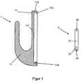
- the hook body 1 of the holding deviceis shown in a lateral section.
- the hook wall 11 of the hook body 1consists of a preferably rectangular plate 111, which is completely surrounded by a protruding border 112.
- An edge 113is formed on the section of the border 112 located above, so that a space is formed between the plate 111 and the edge 113, into which a projection 25 of the base plate 2 engages.
- the edge 113undercuts the base plate 2.
- a total of two eyelets 114are provided on the lower section of the border 112, which protrude into the interior of the border 112 and which serve to receive two pins 34 of the hinge element 3.
- the hinge element 3has a substantially rectangular shaped body 31. On the upper side surface of the body 31 there are two outer eyelets 32 each for receiving the pins 23, 24 of the base plate 2 serve. In the lower area of the body 31 are two bulges 33 are formed. In the bulges 33 there are two pins 34 provided, which are aligned parallel to the lower side surface of the body 31 and which engage in the eyelets 114 of the hook body 1.
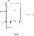
- FIG. 2shows the base plate 2 and the base plate 2 glued by means of an adhesive strip 3 in a side view, the protruding area of the adhesive strip 3 being non-adhesive, ie forming a grip for the adhesive strip 3.
- the base plate 2consists of an essentially rectangular-shaped base 21. In the lower region of the base 21 there is an extension 22 which carries two pins 23, 24 on its side surfaces. The pins 23, 24 are aligned parallel to the lower edge of the base 21, do not protrude beyond the sides of the base 21 and engage in the eyelets 32 of the hinge element 3 Projection 25 is present, which engages in the space between plate 111 and edge 113.
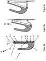
- FIGs 3a to 3cshow the release process of the holding device, consisting of hook body 1 and base plate 2, which is glued to a base 5, for example a tile, by means of the adhesive strip 4.
- the holding deviceis in the permanent adhesive state.
- the base plate 2is fixed by the adhesive tape 4.
- the adhesive strip 4 including the handle, the base plate 2 and the hinge element 3are completely covered by the hook body 1.
- the hinge element 3is attached to the base plate 2.
- the hinge element 3is linked to the hook body 1.
- the hook body 1is attached to the base plate 2 via the edge 113, so that the hook 12 can be loaded.
- the hook body 1is lifted from the base 5, as the arrow A specifies.
- the hook body 1is guided upwards, that is to say parallel to the bonding plane, until the hook body 1 can be removed from the base plate 2. Due to the construction with the hinge element 3, the holding device has a high degree of flexibility without the hook body, the base plate 2 or the hinge element 3 having to be separated from one another.
- the hook body 1is guided upwards until the hinge element 3 is aligned approximately perpendicular to the base 5. Then the grip of the adhesive strip 4 is freely accessible and can be detached from the substrate 5 by pulling in the direction of the bonding plane, because the tensile forces lead to a reduction in the adhesive forces. At the same time, the adhesive strip 4 is also detached from the base plate 2, so that the holding device is also removed from the substrate and can be glued again.
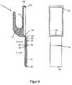
- FIG. 1Another preferred embodiment of the holding device is shown in FIG.
- the holding device shown herediffers from that of FIGS. 1 and 2 in that the connection between the hook body 1 and the hinge element 3 or between the base plate 2 and the hinge element 3 does not take place via eyelets and pins but through film hinges 115, 34.
- the portion of the border 112 located at the bottom, the hinge edge 114, on the hook body 1is chamfered at an angle of 45 °.
- the hinge element 3is articulated via the film hinge 115.
- the hinge element 3consists of an essentially rectangular-shaped body 31, the upper edge 32 of which is chamfered at an angle of 45 ° such that the hinge edge 114 and the edge 32 can lie on one another.
- the lower edge 33is also beveled at an angle of 45 °.
- the base plate 2is articulated via the film hinge 34 by means of the edge 22.
- the edge 22is also bevelled at an angle of 45 °, with a parallel orientation of the base plate 2 and the hinge element 3 between the edge 22 and the edge 333, a V-shaped cutout of 90 ° is provided, thus the necessary mobility of the film hinge 34 to ensure.
- FIGS. 5a to 5cshow the detaching process of the holding device shown in FIG. 4 described. The procedure corresponds exactly to the process as in the Figures 3a to 3c is set out.
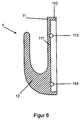
- FIG. 6shows a further preferred embodiment of the hook body 1 of the holding device in a lateral section.
- the hook wall 11 of the hook body 1consists of a preferably rectangular plate 111, which is completely surrounded by a protruding border 112. Directly below the plate 111 there are a total of four blind holes 113, 114 in the border 112, which are each arranged in pairs opposite one another.
- the blind holes 113, 114serve to receive the pins 32, 33, 42, 43 present on the hinge elements 3, 4.
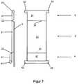
- FIG. 7shows the base plate 2, which together with the hook body 1 according to FIG. 6 forms a holding device.
- the base plate 2consists of a rectangular-shaped bottom 21.
- a first hinge element 3is articulated via a film hinge 22, so that the base plate 2 and the hinge elements 3 lie in one plane.
- the adjacent edges on hinge element 3 and base plate 3are chamfered at an angle of 45 °.
- On the upper edge of the film hinge 3laterally projecting pins 32, 33 are present, which engage in the blind holes 13 of the hook body 1.
- a second hinge element 4is articulated via a film hinge 23, so that the second hinge element is arranged diagonally offset from the base plate 2.
- laterally projecting pins 42, 43are present on the lower edge of the hinge element 4, which engage in the blind holes 14 of the hook device 1.
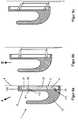
- FIGS 8a to 8cdisclose the principle of operation of this holding device and the release process, consisting of hook body 1, first hinge elements 3, second hinge element 4, base plate 2, which is glued to a base 6, for example a tile, by means of the adhesive strip 5.
- 8ashows the holding device in the permanent adhesive state.
- the base plate 2is fixed by the adhesive tape 5.
- the adhesive strip 5 together with the handle, the base plate 2 and the two hinge elements 3, 4are completely covered by the hook body 1.
- To release the hook body 1is lifted from the surface 6 according to arrow A.
- the hook body 1is guided upwards according to arrow B, that is to say parallel to the bonding plane. Due to the construction with two hinge elements 3, 4 of the same shape, the hook body 1 executes a movement parallel to the base 6.
- the handle of the adhesive tape 5is freely accessible.
- the adhesive strip 5can be detached from the substrate 6 because the tensile forces lead to a reduction in the adhesive forces.
- the adhesive strip 5is also detached from the base plate 2, so that the holding device is also removed from the substrate and can be glued again.
Landscapes
- Supports Or Holders For Household Use (AREA)
Abstract
Description
Translated fromGermanDie Erfindung betrifft eine Haltevorrichtung, die mittels auf Zug entklebende Klebstreifenreversibel verklebbar und wieder verwendbar ist, ggf. mit einem neuen solchen Klebstreifen.The invention relates to a holding device by means of adhesive strips which strip off on the trainis reversibly glued and reusable, if necessary with a new adhesive tape.
Auf Zug entklebende Klebstreifen sind als
So beschreibt US 4,024,312 ein Selbstklebeband mit einem dehnbaren und elastischenTräger aus einem Blockcopolymeren, insbesondere für Anwendungen im medizinischenBereich, wo ein schmerzloses Abziehen von der Haut erwünscht ist.No. 4,024,312 describes a self-adhesive tape with a stretchable and elasticCarrier made from a block copolymer, in particular for medical applicationsArea where painless peeling from the skin is desired.
Weiterhin beschreibt DE 33 31 016 A1 eine Klebfolie für wiederlösbare Klebbindungen,die es gestattet, daß eine damit hergestellte Klebbindung durch Ziehen an der Klebfoliein Richtung der Verklebungsebene lösbar ist. Mit solchen Klebfolie lassen sich hoheKlebkräfte und Scherfestigkeiten erzielen und Klebverbunde ohne weitere Hilfsmittelwieder lösen, vergleichbar dem Öffnen eines Weckglases, ähnlich wie dort die Gummidichtungam Anfasser aus der Dichtungsfuge gezogen wird.DE 33 31 016 A1 also describes an adhesive film for releasable adhesive bonds,which allows an adhesive bond produced therewith by pulling on the adhesive filmis releasable in the direction of the bond plane. With such adhesive film can be highAchieve adhesive forces and shear strengths and adhesive bonds without any additional aidsloosen again, comparable to opening a mason jar, similar to the rubber seal therepulled out of the sealing joint by the handle.
Ferner beschreibt DE 37 14 453 C1 einen zerstörungsfrei von Übungsobjekten wiederabnehmbaren Übungssprengkörper, der mit solch einer Klebfolie reversibel befestigtwird.Furthermore, DE 37 14 453 C1 describes a non-destructive exercise object againdetachable training explosive device, which is reversibly attached with such an adhesive filmbecomes.
Auch WO 92/11333 beschreibt unter anderem Klebfolien für entsprechende Anwendungen,wobei die eingesetzten Klebfolien eine geringe Elastizität bei gleichzeitig hoherDehnung aufweisen.WO 92/11333 also describes, among other things, adhesive films for corresponding applications,the adhesive films used have a low elasticity with a high oneHave stretch.
DE 42 22 849 C1 beschreibt ebenfalls einen Streifen einer Klebfolie dieser Art mit einembesonders ausgestatteten Anfasser.DE 42 22 849 C1 also describes a strip of this type of adhesive film with aspecially equipped handle.
Auch Haken oder ähnliche Befestigungssysteme für die Verwendung zusammen mitsolchen Klebstreifen sind im Handel alstesa Power-Strips mit Haken" oder auch
tesaPower-Strips Systemhaken" von der Beiersdorf AG erhältlich.Hooks or similar fastening systems for use with such adhesive strips are also commercially available
tesa power strips with hook "or
tesa Power-Strips system hook "available from Beiersdorf AG.
Schließlich beschreiben DE 42 33 872 C2, DE 195 11 288 B1 und WO 94/21157 wiederablösbareselbstklebende Haken, die ebenfalls mit derartigen Klebfolien ausgerüstetund also wiederablösbar sind.Finally, DE 42 33 872 C2, DE 195 11 288 B1 and WO 94/21157 describe removable onesself-adhesive hooks, which are also equipped with such adhesive filmsand are therefore removable.
Die in den vorgenannten Druckschriften dargestellten Klebstoffsysteme und Haken weisenjedoch auch eine Anzahl von Nachteilen auf:The adhesive systems and hooks shown in the aforementioned publications havebut also a number of disadvantages:
Problematisch ist bei Haken und dergleichen des Standes der Technik einerseits dieoptische Abdeckung des Anfassers, der zum späteren Ziehen die Vorrichtung überragenmuß, aber auch der Schutz dieses Anfassers vor Manipulation oder auch Beschädigung,insbesondere auch Schaden durch UV-Licht.
Auch ist eine mehrteilige Ausgestaltung, wie sie der Stand der Technik lehrt, dann nachteilig,wenn das eine Teil verloren ging oder etwa bei der Montage herunterfiel. DieseGefahr steigt, je kleiner die Haken in ihrer Abmessung werden.The problem with hooks and the like of the prior art is, on the one hand, the optical covering of the handle, which must protrude beyond the device for later pulling, but also the protection of this handle against manipulation or damage, in particular damage by UV light.
A multi-part design, as taught by the prior art, is also disadvantageous if one part was lost or fell off during assembly. This danger increases the smaller the size of the hooks.
Aufgabe der Erfindung war es, hier Abhilfe zu schaffen, insbesondere einen Haken oderdergleichen zu schaffen, der die Nachteile des Standes der Technik nicht oder zumindestnicht in dem Maße aufweist.The object of the invention was to remedy this, in particular a hook orTo create the like, the disadvantages of the prior art not or at leastnot to the extent.
Demgemäß betrifft die Erfindung eine Haltevorrichtung, insbesondere einen Haken, wiesie im einzelnen in den Ansprüchen gekennzeichnet ist. Die Ausführungsformen gemäßden Unteransprüchen sind dabei bevorzugt.Accordingly, the invention relates to a holding device, in particular a hook, such asit is characterized in detail in the claims. The embodiments according tothe subclaims are preferred.
Die erfindungsgemäße Haltevorrichtung besteht aus einem einteiligen Hakenkörper,zumindest einem einteiligen Scharnierelement und einer einteiligen Basisplatte, dieunlösbar miteinander verbunden sind, wobei die Basisplatte für die Verklebung miteinem auf Zug entklebenden Klebstreifen so ausgebildet ist, daß ein Anfasser des Klebstreifensdie Basisplatte übenagt, wobei das Scharnierelement so ausgebildet ist, daßder am Klebstreifen befindliche Anfasser abgedeckt ist und wobei der Hakenkörper soausgebildet ist, daß er die Basisplatte und das Scharnierelement, die beide in einerEbene angeordnet sind, verdeckt.The holding device according to the invention consists of a one-piece hook body,at least a one-piece hinge element and a one-piece base plate, theare non-detachably connected, the base plate for bonding withan adhesive tape detacking on train is designed so that a handle of the adhesive tapethe base plate is gnawed, the hinge element being designed such thatthe handle on the adhesive tape is covered and the hook body is sois formed that he the base plate and the hinge element, both in oneLevel are arranged, covered.
Die Basisplatte und das Scharnierelement sind über ein Scharnier miteinander verbunden.Das Scharnierelement und der Hakenkörper sind ebenfalls über ein Scharnier miteinanderverbunden.
Der Hakenkörper kann an der am Scharnierelement angrenzenden Seite aus derGrundstellung, in der Hakenkörper auf der Basisplatte verankert ist und dabei Basisplatteund Scharnierelement des Klebstreifens verdeckt, nach oben angehoben werdenund wird durch eine Bewegung parallel zur Basisplatte verschoben, so daß ein Zugriffauf den Anfasser möglich ist.The base plate and the hinge element are connected to one another via a hinge. The hinge element and the hook body are also connected to one another via a hinge.
The hook body can be lifted up on the side adjacent to the hinge element from the basic position, in which the hook body is anchored on the base plate and thereby covers the base plate and hinge element of the adhesive strip, and is displaced by a movement parallel to the base plate, so that access to the Handle is possible.
Die Scharniere sind in einer bevorzugten Ausführungsform Filmscharniere.In a preferred embodiment, the hinges are film hinges.
In einer weiteren bevorzugten Ausführungsform sind an der oberen Kante der Basisplatteund am Hakenkörper ein oberes Scharnierelement sowie an der unteren Kanteder Basisplatte und am Hakenkörper ein unteres Scharnierelement angelenkt, die vorzugsweisegleiche Abmessungen aufweisen.In a further preferred embodiment are on the upper edge of the base plateand an upper hinge element on the hook body and on the lower edgethe base plate and a lower hinge element articulated on the hook body, which preferablyhave the same dimensions.
Der Hakenkörper und/oder die Basisplatte sind vorzugsweise aus Metall oder Kunststoff,ganz besonders bevorzugt Polyethylenterephthalat, Polystyrol oder ABS, gefertigt.The hook body and / or the base plate are preferably made of metal or plastic,very particularly preferably made of polyethylene terephthalate, polystyrene or ABS.
Der Hakenkörper weist vorteilhafterweise eine Umrandung auf, die die Basisplatte undden hinter diese zu klebenden Klebstreifen seitlich umfassen und optisch abdecken.The hook body advantageously has a border that the base plate andenclose the adhesive tape to be glued behind these and cover them optically.
Schließlich weist die Haltevorrichtung einen hinter die Basisplatte geklebten Klebstreifenauf.Finally, the holding device has an adhesive strip glued behind the base plateon.
Mit Hilfe der erfindungsgemäßen Haltevorrichtung lassen sich die aus dem Stand derTechnik bekannten Nachteile hervorragend vermeiden.With the help of the holding device according to the invention can be from the prior artAvoid well-known disadvantages.
Bei der Haltevorrichtung kann kein Teil verloren gehen.
Der Hakenkörper kann auch zum Festhalten während des Strippvorganges verwendetwerden.
Weiterhin ist ein Materialmix bei Hakenkörper und Basisplatte möglich, d.h., je nachAnwendungsfall ist eine optimale Auswahl der Materialien möglich.No part can be lost in the holding device.
The hook body can also be used to hold on during the stripping process.
A mix of materials is also possible for the hook body and base plate, ie depending on the application, an optimal selection of materials is possible.
Das Grundprinzip des Ablösevorganges dieser Haltevorrichtung besteht darin, daß derHakenkörper, der auf der Basisplatte sitzt und dabei diese vollständig abdeckt, verschobenwird, um damit den Zugang zu dem Klebstreifen freizugeben.The basic principle of the detachment process of this holding device is that theHook body, which sits on the base plate and completely covers it, movedto allow access to the adhesive tape.
Im folgenden sollen anhand mehrerer Figuren erfindungsgemäße, besonders vorteilhaftgestaltete Ausführungsformen der Haltevorrichtung näher dargelegt werden, ohne damitdie Erfindung unnötig einschränken zu wollen.In the following, several figures according to the invention are to be particularly advantageousdesigned embodiments of the holding device are set out in more detail without itwant to unnecessarily limit the invention.
Im einzelnen zeigen
Figur 1- eine Ausführungsform des Hakenkörpers der Haltevorrichtungsowie das zugehörige Scharnierelement in seitlicher Ansicht,
Figur 2- die Basisplatte der Haltevorrichtung in der Draufsicht sowie die miteinem Klebstrerten verklebte Basisplatte,
- Figur 3a bis 3c
- den Vorgang der Ablösung der Hattevorrichtung mit der Basisplatteaus
Figur 2, die mittels eines Klebstreifens auf einem Untergrundklebt worden ist, Figur 4- eine andere bevorzugte Ausführungsform des Hakenkörpers mitder Basisplatte der Haltevorrichtung in der Draufsicht sowie die miteinem Klebstreifen verklebte Basisplatte der Haltevorrichtung inseitlicher Ansicht,
- Figur 5a bis 5c
- den Vorgang der Ablösung der Haltevorrichtung mit der Basisplatteaus
Figur 4, die mittels eines Klebstreifens auf einem Untergrundverklebt worden ist, Figur 6- eine weitere bevorzugte Ausführungsform des Hakenkörpers derHaltevorrichtung in seitlicher Ansicht,
- Figur 7
- die Basisplatte der Haltevorrichtung in der Draufsicht sowie die miteinem Klebstreifen verklebte Basisplatte, wobei an der Basisplattezwei Scharnierelemente angelenkt sind,
- Figur 8a bis 8c
- den Vorgang der Ablösung der Haltevorrichtung mit der Basisplatteaus
Figur 6, die mittels eines Klebstreifens auf einem Untergrundverklebt worden ist.
- Figure 1
- An embodiment of the hook body of the holding device and the associated hinge element in a side view,
- Figure 2
- the base plate of the holding device in plan view and the base plate glued with adhesive,
- Figure 3a to 3c
- the process of detaching the had device with the base plate from FIG. 2, which has been adhered to a substrate by means of an adhesive strip,
- Figure 4
- another preferred embodiment of the hook body with the base plate of the holding device in plan view and the base plate of the holding device glued with an adhesive strip in a side view,
- Figure 5a to 5c
- the process of detaching the holding device with the base plate from FIG. 4, which has been glued to an underground by means of an adhesive strip,
- Figure 6
- another preferred embodiment of the hook body of the holding device in a side view,
- Figure 7
- the base plate of the holding device in plan view and the base plate glued with an adhesive strip, two hinge elements being articulated on the base plate,
- Figure 8a to 8c
- the process of detaching the holding device with the base plate from Figure 6, which has been glued to an underground by means of an adhesive strip.
In der Figur 1 ist der Hakenkörper 1 der Haltevorrichtung im seitlichen Schnitt dargestellt.Die Hakenwand 11 des Hakenkörpers 1 besteht aus einer bevorzugt rechteckiggeformten Platte 111, die vollständig von einer überstehenden Umrandung 112 umgebenist. An dem oben befindlichen Abschnitt der Umrandung 112 ist eine Kant 113 ausgeformt,so daß zwischen Platte 111 und Kante 113 ein Zwischenraum entsteht, in dieein Vorsprung 25 der Basisplatte 2 eingreift. Die Kante 113 hinterschneidet dabei dieBasisplatte 2. Am unten befindlichen Abschnitt der Umrandung 112 sind insgesamt zweiÖsen 114 vorhanden, die in das Innere der Umrandung 112 ragen und die zur Aufnahmevon zwei Zapfen 34 des Scharnierelements 3 dienen.
Auf der Hakenwand 11, und zwar der Umrandung 112 gegenüber, ist ein Haken 12angeformt, der zur Aufnahme von beliebigen Gegenständen dient, beispielsweise Kleidungsstücken,Handtüchern etc.In Figure 1, the
On the
Des weiteren zeigt die Figur 1 das Scharnierelement 3. Das Scharnierelement 3 weisteinen im wesentlichen rechteckig geformten Körper 31 auf. An der oberen Seitenflächedes Körpers 31 sind jeweils außen liegende zwei Ösen 32 vorhanden, die zur Aufnahmeder Zapfen 23, 24 der Basisplatte 2 dienen. Im unteren Bereich des Körpers 31 sindzwei Ausbuchtungen 33 ausgeformt. In den Ausbuchtungen 33 sind zwei Zapfen 34vorgesehen, die parallel zur unteren Seitenfläche des Körpers 31 ausgerichtet sind unddie in die Ösen 114 des Hakenkörpers 1 eingreifen.1 shows the
Die Figur 2 zeigt die Basisplatte 2 sowie die mittels eines Klebstreifens 3 verklebteBasisplatte 2 in seitlicher Ansicht, wobei der überstehende Bereich des Klebstreifens 3nicht klebend ausgerüstet ist, also einen Anfasser für den Klebstreifen 3 bildet. DieBasisplatte 2 besteht aus einem im wesentlichen rechteckig geformten Boden 21. Imunten liegenden Bereich des Bodens 21 ist eine Erweiterung 22 vorhanden, die an ihrenSeitenflächen zwei zapfen 23, 24 trägt. Die Zapfen 23, 24 sind parallel zur unterenKante des Bodens 21 ausgerichtet, ragen nicht über die Seiten des Bodens 21 hinausund greifen in die Ösen 32 des Scharnierelements 3. Am oben liegenden Bereich desBodens 21 ist ein
Vorsprung 25 vorhanden, der in den Zwischenraum zwischen Platte 111 und Kante 113greift.FIG. 2 shows the
Die Figuren 3a bis 3c zeigen den Lösungsvorgang der Haltevorrichtung, bestehend ausHakenkörper 1 und Basisplatte 2, die vermittels des Klebstreifens 4 auf einem Untergrund5, zum Beispiel einer Kachel, verklebt ist. In der Figur 3a ist die Haltevorrichtungim dauerhaften Verklebezustand. Dazu ist die Basisplatte 2 durch den Klebstreifen 4fixiert. Der Klebstreifen 4 samt Anfasser, die Basisplatte 2 und das Scharnierelement 3sind vollständig vom Hakenkörper 1 abgedeckt. An der Basisplatte 2 ist das Scharnierelement3 angehängt. Das Scharnierelement 3 ist mit dem Hakenkörper 1 verknüpft. DerHakenkörper 1 ist über die Kante 113 an der Basisplatte 2 angehängt, so daß derHaken 12 belastet werden kann.
Zum Lösen der Haltevorrichtung von der Wand wird der Hakenkörper 1 vom Untergrund5 angehoben, wie es der Pfeil A vorgibt. Anschließend wird der Hakenkörper 1 gemäßPfeil B nach oben, also parallel zur Verklebungsebene, geführt, bis der Hakenkörper 1von der Basisplatte 2 entfernt werden kann.
Bedingt durch die Konstruktion mit dem Scharnierelement 3 weist die Haltevorrichtungeine hohe Flexibilität auf, ohne daß der Hakenkörper, die Basisplatte 2 oder das Scharnierelement3 voneinander getrennt werden müssen. Vorteilhafterweise wird der Hakenkörper1 soweit nach oben geführt, bis das Scharnierelement 3 annähernd senkrechtzum Untergrund 5 ausgerichtet ist. Dann ist der Anfasser des Klebstreifens 4 freizugänglich und kann durch Ziehen in Richtung der Verklebungsebene vom Untergrund5 abgelöst werden, weil die Zugkräfte zu einer Reduzierung der Klebkräfte führen.Gleichzeitig wird der Klebstreifen 4 aber auch von der Basisplatte 2 abgelöst, so daß die Haltevorrichtung ebenfalls vom Untergrund entfernt ist und wieder verklebt werdenkann.Figures 3a to 3c show the release process of the holding device, consisting of
To release the holding device from the wall, the
Due to the construction with the
In der Figur 4 ist ein andere bevorzugte Ausführungsform der Haltevorrichtung dargestellt.Die hier gezeigte Haltevorrichtung unterscheidet sich von der aus den Figuren 1und 2 dadurch, daß die Verbindung zwischen Hakenkörper 1 und Scharnierelement 3beziehungsweise zwischen Basisplatte 2 und Scharnierelement 3 nicht über Ösen undZapfen sondern durch Filmscharniere 115, 34 erfolgt. Dazu ist am Hakenkörper 1 derunten befindliche Abschnitt der Umrandung 112, die Scharnierkante 114, in einem Winkelvon 45° abgeschrägt.
Über das Filmscharnier 115 ist das Scharnierelemente 3 angelenkt. Das Scharnierelement3 besteht aus einem im wesentlichen rechteckig geformten Körper 31, dessenobere Kante 32 so in einem Winkel von 45° abgeschrägt ist, daß die Scharnierkante 114und die Kante 32 aufeinander liegen können. Die untere Kante 33 ist ebenfalls in einemWinkel von 45° abgeschrägt.
Über das Filmscharnier 34 ist mittels der Kante 22 die Basisplatte 2 angelenkt. De Kante22 ist ebenfalls in einem Winkel von 45° abgeschrägt, wobei bei paralleler Ausrichtungder Basisplatte 2 und des Scharnierelementes 3 zwischen der Kante 22 und der Kante333 ein V-förmiger Ausschnitt von 90° vorhanden ist, um somit die notwendige Beweglichkeittdes Filmscharniers 34 zu gewährleisten.Another preferred embodiment of the holding device is shown in FIG. The holding device shown here differs from that of FIGS. 1 and 2 in that the connection between the
The
The
In den Figuren 5a bis 5c ist der Ablösevorgang der in Figur 4 gezeigten Haltevorrichtungbeschrieben. Dieser entspricht in seinem Vorgehen exakt dem Vorgang, wie er in denFiguren 3a bis 3c dargelegt ist.FIGS. 5a to 5c show the detaching process of the holding device shown in FIG. 4described. The procedure corresponds exactly to the process as in theFigures 3a to 3c is set out.
In der Figur 6 ist eine weitere bevorzugte Ausführungsform des Hakenkörpers 1 der Haltevorrichtungim seitlichen Schnitt dargestellt.
Die Hakenwand 11 des Hakenkörpers 1 besteht aus einer bevorzugt rechteckig geformtenPlatte 111, die vollständig von einer überstehenden Umrandung 112 umgeben ist.Direkt unterhalb der Platte 111 sind insgesamt vier Sacklöcher 113, 114 in der Umrandung112 vorhanden, die jeweils paarweise gegenüber angeordnet sind. Die Sacklöcher113, 114 dienen zur Aufnahme der an den Scharnierelementen 3, 4 vorhandene Zapfen32, 33, 42, 43.FIG. 6 shows a further preferred embodiment of the
The
Die Figur 7 zeigt die Basisplatte 2, die zusammen mit dem Hakenkörper 1 nach Figur 6eine Haltevorrichtung bildet. Die Basisplatte 2 besteht aus einem rechteckig geformtenBoden 21. An der oberen Kante ist über ein Filmscharnier 22 ein erste Scharnierelement3 angelenkt, so daß die Basisplatte 2 und das Scharnierelemente 3 in einer Ebene liegen.Um eine ausreichende Beweglichkeit des Filmscharniers zu gewährleisten, sind diebenachbarten Kanten an Scharnierelement 3 und Basisplatte 3 in einem Winkel von 45°abgeschrägt. An der oberen Kante des Filmscharniers 3 sind seitlich überragende Zapfen32, 33 vorhanden, die in die Sacklöcher 13 des Hakenkörpers 1 greifen.
An der unteren Kante der Basisplatte 2 ist über ein Filmscharnier 23 ein zweites Scharnierelement4 angelenkt, so daß das zweite Scharnierelement diagonal versetzt zurBasisplatte 2 angeordnet ist. Wie am ersten Scharnierelement 3 sind an der unterenKante des Scharnierelements 4 seitlich überragende Zapfen 42, 43 vorhanden, die indie Sacklöcher 14 der Hakenvorrichtung 1 greifen.FIG. 7 shows the
At the lower edge of the
Die Figuren 8a bis 8c offenbaren das Funktionsprinzip dieser Haltevorrichtung und denLösungsvorgang, bestehend aus Hakenkörper 1, erstes Scharnierelementen 3, zweitesScharnierelement 4, Basisplatte 2, die vermittels des Klebstreifens 5 auf einem Untergrund6, zum Beispiel einer Kachel, verklebt ist. In der Figur 8a ist die Haltevorrichtungim dauerhaften Verklebezustand gezeigt. Dazu ist die Basisplatte 2 durch den Klebstreifen5 fixiert. Der Klebstreifen 5 samt Anfasser, die Basisplatte 2 und die beiden Scharnierelemente3, 4 sind vollständig vom Hakenkörper 1 abgedeckt.
Zum Lösen wird der Hakenkörper 1 vom Untergrund 6 gemäß Pfeil A angehoben.Anschließend wird der Hakenkörper 1 gemäß Pfeil B nach oben, also parallel zur Verklebungsebene,geführt. Bedingt durch die Konstruktion mit zwei gleichgeformtenScharnierelementen 3, 4 führt der Hakenkörper 1 eine Bewegung parallel zum, Untergrund6 aus. Ist der Hakenkörper 1 ausreichend nach oben geführt, ist der Anfasser desKlebstreifens 5 frei zugänglich. Durch Ziehen in Richtung der Verklebungsebene kannder Klebstreifen 5 vom Untergrund 6 abgelöst werden, weil die Zugkräfte zu einerReduzierung der Klebkräfte führen. Gleichzeitig wird der Klebstreifen 5 aber auch vonder Basisplatte 2 abgelöst, so daß die Haltevorrichtung ebenfalls vom Untergrund entferntist und wieder verklebt werden kann.Figures 8a to 8c disclose the principle of operation of this holding device and the release process, consisting of
To release the
Claims (6)
Translated fromGermandie Scharniere Filmscharniere sind.Had device according to claim 1, characterized in that
the hinges are film hinges.
an der oberen Kante der Basisplatte und am Hakenkörper ein oberes Scharnierelementsowie an der unteren Kante der Basisplatte und am Hakenkörper einunteres Scharnierelement angelenkt sind, die vorzugsweise gleiche Abmessungenaufweisen.Holding device according to claim 1, characterized in that
on the upper edge of the base plate and on the hook body an upper hinge element and on the lower edge of the base plate and on the hook body a lower hinge element are hinged, which preferably have the same dimensions.
der Hakenkörper und/oder die Basisplatte und/oder die Scharnierelemente ausMetall oder Kunststoff, vorzugsweise Polyethylenterephthalat, Polystyrol oder ABS,gefertigt sind.Had device according to claim 1, characterized in that
the hook body and / or the base plate and / or the hinge elements are made of metal or plastic, preferably polyethylene terephthalate, polystyrene or ABS.
der Hakenkörper eine Umrandung aufweist, die die Basisplatte und den hinter diesezu klebenden Klebstreifen seitlich umfassen und optisch abdecken.Holding device according to claim 1, characterized in that
the hook body has a border which laterally surround and optically cover the base plate and the adhesive strip to be glued behind it.
die Hattevorrichtung einen hinter die Basisplatte geklebten Klebstrerten aufweist.Had device according to claim 1, characterized in that
the device had an adhesive glue stuck behind the base plate.
Applications Claiming Priority (2)
| Application Number | Priority Date | Filing Date | Title |
|---|---|---|---|
| DE19735229ADE19735229A1 (en) | 1997-08-14 | 1997-08-14 | Holding device |
| DE97352294 | 1997-08-14 |
Publications (3)
| Publication Number | Publication Date |
|---|---|
| EP0896806A2true EP0896806A2 (en) | 1999-02-17 |
| EP0896806A3 EP0896806A3 (en) | 2004-09-22 |
| EP0896806B1 EP0896806B1 (en) | 2006-11-22 |
Family
ID=7838948
Family Applications (1)
| Application Number | Title | Priority Date | Filing Date |
|---|---|---|---|
| EP98114365AExpired - LifetimeEP0896806B1 (en) | 1997-08-14 | 1998-07-30 | Mounting device |
Country Status (4)
| Country | Link |
|---|---|
| US (1) | US6082686A (en) |
| EP (1) | EP0896806B1 (en) |
| DE (2) | DE19735229A1 (en) |
| ES (1) | ES2276440T3 (en) |
Cited By (2)
| Publication number | Priority date | Publication date | Assignee | Title |
|---|---|---|---|---|
| WO2011162998A1 (en)* | 2010-06-25 | 2011-12-29 | 3M Innovative Properties Company | Adjustable mounting assembly for easel pads |
| EP2654517A4 (en)* | 2010-12-20 | 2014-05-07 | 3M Innovative Properties Co | Article support device comprising a rotatable connection |
Families Citing this family (23)
| Publication number | Priority date | Publication date | Assignee | Title |
|---|---|---|---|---|
| DE10107422A1 (en)* | 2001-02-14 | 2002-08-22 | Tesa Ag | At least two-part hook |
| US6641096B2 (en) | 2001-09-13 | 2003-11-04 | 3M Innovative Properties Company | Stretch releasing adhesive tape article with bundling strap |
| US6811126B2 (en)* | 2001-09-13 | 2004-11-02 | 3M Innovative Properties Company | Stretch releasing adhesive tape article with flexible cover |
| DE10207935A1 (en)* | 2002-02-23 | 2003-09-04 | Tesa Ag | fastener |
| DE10236547A1 (en)* | 2002-08-08 | 2004-02-19 | Tesa Ag | At least two-part holding device |
| US6832445B2 (en) | 2002-12-31 | 2004-12-21 | 3M Innovative Properties Company | Graphic display device mountable with stretch releasing adhesive |
| US7185864B2 (en)* | 2003-10-01 | 2007-03-06 | Adams Mfg. Corp. | Door hook with hinge |
| US20070257165A1 (en)* | 2005-06-21 | 2007-11-08 | Peter Newbould | Article support device mountable with stretch releasing adhesive |
| US8708305B2 (en) | 2010-08-04 | 2014-04-29 | 3M Innovative Properties Company | Adhesively mounted article support assembly with exposed pull tab |
| US10925417B2 (en) | 2014-01-22 | 2021-02-23 | Ccl Label, Inc. | Secure hold hook |
| CN104921574A (en)* | 2014-03-21 | 2015-09-23 | 蓝永辉 | Adhesive wall support structure |
| CA2930808A1 (en) | 2014-06-17 | 2015-12-23 | 3M Innovative Properties Company | Article support using peel release adhesives |
| WO2017136279A1 (en) | 2016-02-01 | 2017-08-10 | 3M Innovative Properties Company | Conformable, peelable adhesive articles |
| EP3411448A1 (en) | 2016-02-01 | 2018-12-12 | 3M Innovative Properties Company | Improved pressure sensitive adhesive compositions |
| TWI722105B (en) | 2016-02-01 | 2021-03-21 | 美商3M新設資產公司 | Conformable, stretch releasable adhesive articles |
| JP2020515324A (en) | 2017-03-28 | 2020-05-28 | スリーエム イノベイティブ プロパティズ カンパニー | Shape-compatible adhesive article |
| US10221883B2 (en)* | 2017-04-07 | 2019-03-05 | Artskills, Inc. | Apparatus for supporting articles |
| EP3645900A4 (en) | 2017-06-28 | 2021-03-24 | 3M Innovative Properties Company | Adhesive mounting devices having patterned adhesive regions |
| CN111032331B (en) | 2017-08-25 | 2022-05-13 | 3M创新有限公司 | Adhesive article allowing for non-destructive removal |
| BR112020003831B1 (en) | 2017-08-25 | 2023-03-07 | 3M Innovative Properties Company | ADHESIVE ARTICLE FOR MOUNTING AN OBJECT ON A SURFACE |
| US12369732B2 (en) | 2019-01-04 | 2025-07-29 | 3M Innovative Properties Company | Adjustable adhesive articles with permissible movement parallel to bonding plane |
| WO2022079557A1 (en) | 2020-10-15 | 2022-04-21 | 3M Innovative Properties Company | Adhesive assemblies permitting enhanced weight bearing performance with damage free removal |
| DE102021200334B3 (en) | 2021-01-15 | 2022-07-14 | Tesa Se | Self-adhesive device |
Citations (13)
| Publication number | Priority date | Publication date | Assignee | Title |
|---|---|---|---|---|
| US4024312A (en) | 1976-06-23 | 1977-05-17 | Johnson & Johnson | Pressure-sensitive adhesive tape having extensible and elastic backing composed of a block copolymer |
| DE3331016A1 (en) | 1983-04-06 | 1984-10-11 | Beiersdorf Ag, 2000 Hamburg | Adhesive film for releasable adhesive bonds |
| DE3714453C1 (en) | 1987-04-30 | 1988-12-01 | Dynamit Nobel Ag | Practice explosive body which can be removed again from practice objects non-destructively |
| WO1992011332A1 (en) | 1990-12-20 | 1992-07-09 | Minnesota Mining And Manufacturing Company | Removable adhesive tape |
| WO1992011333A1 (en) | 1990-12-20 | 1992-07-09 | Minnesota Mining And Manufacturing Company | Removable adhesive tape |
| DE4222849C1 (en) | 1992-07-11 | 1993-06-17 | Beiersdorf Ag, 2000 Hamburg, De | |
| DE4233872C2 (en) | 1992-09-30 | 1994-07-28 | Beiersdorf Ag | Removable, self-adhesive hook |
| WO1994021157A1 (en) | 1993-03-23 | 1994-09-29 | Minnesota Mining And Manufacturing Company | Article support using stretch releasing adhesives |
| WO1995006691A1 (en) | 1993-08-31 | 1995-03-09 | Minnesota Mining And Manufacturing Company | Removable foam adhesive tape |
| DE4339604A1 (en) | 1993-11-20 | 1995-05-24 | Beiersdorf Ag | Use of a strip of self-adhesive film for removable bonds |
| DE4428587A1 (en) | 1994-08-12 | 1996-02-15 | Beiersdorf Ag | Adhesive film strips |
| DE4431914A1 (en) | 1994-09-08 | 1996-03-14 | Beiersdorf Ag | Adhesive film strips |
| DE19511288A1 (en) | 1995-03-28 | 1996-10-02 | Beiersdorf Ag | Use of a section of adhesive film for residue-free and damage-free removable removal |
Family Cites Families (9)
| Publication number | Priority date | Publication date | Assignee | Title |
|---|---|---|---|---|
| GB493686A (en)* | 1937-03-22 | 1938-10-12 | Marinus Johannes Dirk De Geus | Improvements relating to suspension devices for securing hooks, brackets and the like to fixed surfaces |
| US3561077A (en)* | 1970-02-18 | 1971-02-09 | Ethan C Grant | Hanger for litter bags and the like |
| US3637181A (en)* | 1970-03-16 | 1972-01-25 | Minnesota Mining & Mfg | Adhesive fixture |
| GB1560552A (en)* | 1976-01-28 | 1980-02-06 | Petit J A L | Cable clips |
| US4310137A (en)* | 1980-09-08 | 1982-01-12 | Frye Bruce J | Self holding separable mount |
| US4986504A (en)* | 1989-01-06 | 1991-01-22 | Gary Products Group, Inc. | Decorative light pedestal with hinged closure |
| US5507464A (en)* | 1994-03-22 | 1996-04-16 | Minnesota Mining And Manufacturing Company | Article support using stretch releasing adhesives |
| US5695161A (en)* | 1995-12-20 | 1997-12-09 | American Greetings Corporation | Hinged product display clip |
| US5890688A (en)* | 1997-10-02 | 1999-04-06 | Riordan; James | Device for releasably mounting a business or calling card |
- 1997
- 1997-08-14DEDE19735229Apatent/DE19735229A1/ennot_activeWithdrawn
- 1998
- 1998-07-30ESES98114365Tpatent/ES2276440T3/ennot_activeExpired - Lifetime
- 1998-07-30DEDE59813815Tpatent/DE59813815D1/ennot_activeExpired - Lifetime
- 1998-07-30EPEP98114365Apatent/EP0896806B1/ennot_activeExpired - Lifetime
- 1998-08-11USUS09/132,394patent/US6082686A/ennot_activeExpired - Lifetime
Patent Citations (13)
| Publication number | Priority date | Publication date | Assignee | Title |
|---|---|---|---|---|
| US4024312A (en) | 1976-06-23 | 1977-05-17 | Johnson & Johnson | Pressure-sensitive adhesive tape having extensible and elastic backing composed of a block copolymer |
| DE3331016A1 (en) | 1983-04-06 | 1984-10-11 | Beiersdorf Ag, 2000 Hamburg | Adhesive film for releasable adhesive bonds |
| DE3714453C1 (en) | 1987-04-30 | 1988-12-01 | Dynamit Nobel Ag | Practice explosive body which can be removed again from practice objects non-destructively |
| WO1992011332A1 (en) | 1990-12-20 | 1992-07-09 | Minnesota Mining And Manufacturing Company | Removable adhesive tape |
| WO1992011333A1 (en) | 1990-12-20 | 1992-07-09 | Minnesota Mining And Manufacturing Company | Removable adhesive tape |
| DE4222849C1 (en) | 1992-07-11 | 1993-06-17 | Beiersdorf Ag, 2000 Hamburg, De | |
| DE4233872C2 (en) | 1992-09-30 | 1994-07-28 | Beiersdorf Ag | Removable, self-adhesive hook |
| WO1994021157A1 (en) | 1993-03-23 | 1994-09-29 | Minnesota Mining And Manufacturing Company | Article support using stretch releasing adhesives |
| WO1995006691A1 (en) | 1993-08-31 | 1995-03-09 | Minnesota Mining And Manufacturing Company | Removable foam adhesive tape |
| DE4339604A1 (en) | 1993-11-20 | 1995-05-24 | Beiersdorf Ag | Use of a strip of self-adhesive film for removable bonds |
| DE4428587A1 (en) | 1994-08-12 | 1996-02-15 | Beiersdorf Ag | Adhesive film strips |
| DE4431914A1 (en) | 1994-09-08 | 1996-03-14 | Beiersdorf Ag | Adhesive film strips |
| DE19511288A1 (en) | 1995-03-28 | 1996-10-02 | Beiersdorf Ag | Use of a section of adhesive film for residue-free and damage-free removable removal |
Cited By (4)
| Publication number | Priority date | Publication date | Assignee | Title |
|---|---|---|---|---|
| WO2011162998A1 (en)* | 2010-06-25 | 2011-12-29 | 3M Innovative Properties Company | Adjustable mounting assembly for easel pads |
| EP2654517A4 (en)* | 2010-12-20 | 2014-05-07 | 3M Innovative Properties Co | Article support device comprising a rotatable connection |
| AU2011349754B2 (en)* | 2010-12-20 | 2015-09-10 | 3M Innovative Properties Company | Article support device comprising a rotatable connection |
| KR101891848B1 (en) | 2010-12-20 | 2018-08-24 | 쓰리엠 이노베이티브 프로퍼티즈 컴파니 | Article support device comprising a rotatable connection |
Also Published As
| Publication number | Publication date |
|---|---|
| EP0896806A3 (en) | 2004-09-22 |
| DE19735229A1 (en) | 1999-02-18 |
| ES2276440T3 (en) | 2007-06-16 |
| EP0896806B1 (en) | 2006-11-22 |
| DE59813815D1 (en) | 2007-01-04 |
| US6082686A (en) | 2000-07-04 |
Similar Documents
| Publication | Publication Date | Title |
|---|---|---|
| EP0896806B1 (en) | Mounting device | |
| EP0896805B1 (en) | Mounting device | |
| EP0896807B1 (en) | Mounting device | |
| EP0861622B1 (en) | Mounting device | |
| DE19511288C2 (en) | Use of a double-sided adhesive film section for fixing or hanging an object | |
| DE69520786T2 (en) | SEALING TAPE AND ITS METHOD OF USE | |
| DE69310593T2 (en) | Method of attaching a fastening tape to a molded body and associated mold | |
| DE69705710T2 (en) | COMPRESSIBLE SHEET DISPENSER | |
| EP0832587B1 (en) | Removable adhesive device | |
| DE69116562T2 (en) | LONG, BENDABLE DEVICE | |
| DE9412451U1 (en) | Fastening device | |
| DE69612791T2 (en) | Magnetic door seal for infant incubator | |
| EP1232708B1 (en) | Hook with at least two parts | |
| EP1405979B1 (en) | Connecting device, cover and partition wall element | |
| EP0508948B1 (en) | Plastic key holder and hanging device for same | |
| EP1216637B1 (en) | Removable self-adhesive device | |
| EP1004713B1 (en) | Covering rosette | |
| DE19955177A1 (en) | Wall and ceiling hooks | |
| EP1388316B1 (en) | Holding device comprising at least two elements | |
| AT403875B (en) | CLIPS | |
| EP0839987A1 (en) | Hook for a fly screen | |
| DE4447601A1 (en) | Fastener for waistband with holes of girdle | |
| EP1209091A1 (en) | Band for closing bags | |
| EP2634357A1 (en) | Anti-insect device and positioning aid for positioning same | |
| DE2447122A1 (en) | HINGE FOR DOORS OD. DGL. |
Legal Events
| Date | Code | Title | Description |
|---|---|---|---|
| PUAI | Public reference made under article 153(3) epc to a published international application that has entered the european phase | Free format text:ORIGINAL CODE: 0009012 | |
| AK | Designated contracting states | Kind code of ref document:A2 Designated state(s):AT BE CH CY DE DK ES FI FR GB GR IE IT LI LU MC NL PT SE | |
| AX | Request for extension of the european patent | Free format text:AL;LT;LV;MK;RO;SI | |
| RAP1 | Party data changed (applicant data changed or rights of an application transferred) | Owner name:TESA AG | |
| PUAL | Search report despatched | Free format text:ORIGINAL CODE: 0009013 | |
| RAP1 | Party data changed (applicant data changed or rights of an application transferred) | Owner name:TESA AG | |
| AK | Designated contracting states | Kind code of ref document:A3 Designated state(s):AT BE CH CY DE DK ES FI FR GB GR IE IT LI LU MC NL PT SE | |
| AX | Request for extension of the european patent | Extension state:AL LT LV MK RO SI | |
| 17P | Request for examination filed | Effective date:20050322 | |
| AKX | Designation fees paid | Designated state(s):DE ES FR GB IT | |
| GRAP | Despatch of communication of intention to grant a patent | Free format text:ORIGINAL CODE: EPIDOSNIGR1 | |
| GRAS | Grant fee paid | Free format text:ORIGINAL CODE: EPIDOSNIGR3 | |
| GRAA | (expected) grant | Free format text:ORIGINAL CODE: 0009210 | |
| AK | Designated contracting states | Kind code of ref document:B1 Designated state(s):DE ES FR GB IT | |
| REG | Reference to a national code | Ref country code:GB Ref legal event code:FG4D Free format text:NOT ENGLISH | |
| GBT | Gb: translation of ep patent filed (gb section 77(6)(a)/1977) | Effective date:20061213 | |
| REF | Corresponds to: | Ref document number:59813815 Country of ref document:DE Date of ref document:20070104 Kind code of ref document:P | |
| ET | Fr: translation filed | ||
| REG | Reference to a national code | Ref country code:ES Ref legal event code:FG2A Ref document number:2276440 Country of ref document:ES Kind code of ref document:T3 | |
| PLBE | No opposition filed within time limit | Free format text:ORIGINAL CODE: 0009261 | |
| STAA | Information on the status of an ep patent application or granted ep patent | Free format text:STATUS: NO OPPOSITION FILED WITHIN TIME LIMIT | |
| 26N | No opposition filed | Effective date:20070823 | |
| PGFP | Annual fee paid to national office [announced via postgrant information from national office to epo] | Ref country code:IT Payment date:20080724 Year of fee payment:11 | |
| PGFP | Annual fee paid to national office [announced via postgrant information from national office to epo] | Ref country code:GB Payment date:20080722 Year of fee payment:11 | |
| PGFP | Annual fee paid to national office [announced via postgrant information from national office to epo] | Ref country code:ES Payment date:20090724 Year of fee payment:12 | |
| GBPC | Gb: european patent ceased through non-payment of renewal fee | Effective date:20090730 | |
| REG | Reference to a national code | Ref country code:FR Ref legal event code:CJ Ref country code:FR Ref legal event code:CD | |
| PG25 | Lapsed in a contracting state [announced via postgrant information from national office to epo] | Ref country code:GB Free format text:LAPSE BECAUSE OF NON-PAYMENT OF DUE FEES Effective date:20090730 | |
| PG25 | Lapsed in a contracting state [announced via postgrant information from national office to epo] | Ref country code:IT Free format text:LAPSE BECAUSE OF NON-PAYMENT OF DUE FEES Effective date:20090730 | |
| REG | Reference to a national code | Ref country code:ES Ref legal event code:FD2A Effective date:20110818 | |
| PG25 | Lapsed in a contracting state [announced via postgrant information from national office to epo] | Ref country code:ES Free format text:LAPSE BECAUSE OF NON-PAYMENT OF DUE FEES Effective date:20100731 | |
| PGFP | Annual fee paid to national office [announced via postgrant information from national office to epo] | Ref country code:FR Payment date:20120806 Year of fee payment:15 | |
| REG | Reference to a national code | Ref country code:FR Ref legal event code:ST Effective date:20140331 | |
| PG25 | Lapsed in a contracting state [announced via postgrant information from national office to epo] | Ref country code:FR Free format text:LAPSE BECAUSE OF NON-PAYMENT OF DUE FEES Effective date:20130731 | |
| REG | Reference to a national code | Ref country code:DE Ref legal event code:R081 Ref document number:59813815 Country of ref document:DE Owner name:TESA SE, DE Free format text:FORMER OWNER: TESA SE, 20253 HAMBURG, DE | |
| PGFP | Annual fee paid to national office [announced via postgrant information from national office to epo] | Ref country code:DE Payment date:20170724 Year of fee payment:20 | |
| REG | Reference to a national code | Ref country code:DE Ref legal event code:R071 Ref document number:59813815 Country of ref document:DE |