EP0895146A1 - Operating point control device of an electrical energy generator, especially of a solar generator - Google Patents
Operating point control device of an electrical energy generator, especially of a solar generatorDownload PDFInfo
- Publication number
- EP0895146A1 EP0895146A1EP98401903AEP98401903AEP0895146A1EP 0895146 A1EP0895146 A1EP 0895146A1EP 98401903 AEP98401903 AEP 98401903AEP 98401903 AEP98401903 AEP 98401903AEP 0895146 A1EP0895146 A1EP 0895146A1
- Authority
- EP
- European Patent Office
- Prior art keywords
- generator
- signal
- transformer
- primary winding
- operating point
- Prior art date
- Legal status (The legal status is an assumption and is not a legal conclusion. Google has not performed a legal analysis and makes no representation as to the accuracy of the status listed.)
- Granted
Links
- 238000004804windingMethods0.000claimsabstractdescription44
- 230000001276controlling effectEffects0.000claimsdescription5
- 238000009825accumulationMethods0.000claimsdescription4
- 230000001105regulatory effectEffects0.000claimsdescription4
- 230000005611electricityEffects0.000abstract1
- 239000003990capacitorSubstances0.000description5
- 238000004146energy storageMethods0.000description3
- 238000010586diagramMethods0.000description2
- 238000005259measurementMethods0.000description2
- 238000007599dischargingMethods0.000description1
- 230000005669field effectEffects0.000description1
- 238000005286illuminationMethods0.000description1
- 238000002955isolationMethods0.000description1
- 238000012423maintenanceMethods0.000description1
- 230000007257malfunctionEffects0.000description1
- 238000000034methodMethods0.000description1
- 230000003068static effectEffects0.000description1
Images

Classifications
- G—PHYSICS
- G05—CONTROLLING; REGULATING
- G05F—SYSTEMS FOR REGULATING ELECTRIC OR MAGNETIC VARIABLES
- G05F1/00—Automatic systems in which deviations of an electric quantity from one or more predetermined values are detected at the output of the system and fed back to a device within the system to restore the detected quantity to its predetermined value or values, i.e. retroactive systems
- G05F1/66—Regulating electric power
- G05F1/67—Regulating electric power to the maximum power available from a generator, e.g. from solar cell
Definitions
- the present inventionrelates to a device generator operating point control electrical energy, including a solar generator supplying a load and, more particularly, to such a device designed to operate the generator at its maximum power.
- the device describedincludes a width modulation converter of pulses coupled to a current generator, means delivering signals representative of the voltage and of the current delivered by said generator to said converter, means supplied by said signals to signal the existence or not of a state of dropping out of the converter, a width regulation loop pulse itself comprising means for measuring the voltage delivered by the converter to a load, a differential amplifier, inverter, integrator and pulse width modulation means controlling said converter.
- the device describedmakes it possible to eliminate the dropout phenomenon that is observed when the power called by the load becomes greater than the maximum power that the generator can provide. he also allows to regulate the operating point of feeding the load to a corresponding position at the maximum power that this supply can deliver as in any other point of the characteristic generator current / voltage. It is however relatively complex, including two sensors for current intensity and voltage delivered by the generator, and therefore expensive.
- the present inventiontherefore aims to achieve a operating point control device of a solar generator which does not have the disadvantages mentioned above devices of the technique which is therefore simple and of little realization expensive, allowing flexible fixing and regulation the position of the generator operating point, any point of the current / voltage characteristic of this one, and in particular at the point corresponding to the supply of maximum electrical power by said generator.
- This object of the inventionis achieved, as well as other which will appear on reading the description which will track, with a point of control device operation of an electric power generator supplying a load, this device being remarkable in what it includes a) a storage transformer of energy, with primary and secondary sense windings reverse, the primary winding being supplied by the generator under the control of a switch, winding secondary being connected in series with a diode and with the load, b) a detector sensitive to the intensity of the average current flowing in the primary winding of the transformer to deliver a signal representative of this intensity, and c) means for controlling the switch switching, sensitive to said signal for establish a primary winding in the transformer average current corresponding to an operating point predetermined generator.
- this devicefor simple structure, with a single detector, is therefore economical, and yet very flexible to operate.
- this detectoris constituted by a second energy storage transformer comprising primary and secondary windings in opposite directions, the primary winding being traversed by the current flowing in the primary winding of the first transformer, the secondary winding being placed in series with a diode and a load, the signal delivered by the detector being sampled at the terminals of said load.
- control means thereofinclude a signal-powered microcontroller delivered by the detector and representative of the current means circulating in the primary winding of the first electric storage transformer and a amplitude-duration converter supplied by a signal setpoint developed by the microcontroller, to control switching the switch with a signal to pulse width modulation.
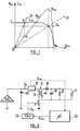
- the graph of this characteristichas, as shown, a generally rectangular shape comprising a part substantially parallel to the axis of the voltages and another part substantially parallel to the axis of the intensities, these two parts being connected by a rounded part.
- a solar generatorordinarily feeds into a storage battery and into various consumers of electrical energy constituted by satellite equipment. The generator operating point is then located at the intersection of its current / voltage characteristic with a load line passing the origin of the coordinates.
- This pointcan thus be located on various parts of the characteristic, for example at its intersection with the load line D 1 , on the part of this characteristic where the current remains substantially constant, ie when the generator operates as a "current generator” . It could likewise be located on the part of the characteristic where the voltage is substantially constant, if we are looking for operation as a "voltage generator”.
- This figureshows the generator solar GS discharging on a load represented by a storage battery 1 and a resistor 2 symbolizing various consumers of electrical energy on board a satellite for example.
- the GS generatordelivers on this load through a energy storage transformer 3, the primary 5 and secondary 6 windings are meaningless inverses as indicated by the points placed on these windings.
- the primary winding 5is supplied by the generator, under the control of a switch 7, advantageously electronic, placed in series with this winding between a terminal thereof and ground.
- transformer 3is associated with a diode 8 arranged in series with the winding 6 and a capacitor 9 mounted between the terminals of the winding, in parallel with the load 1.2.
- Another capacitor 10is mounted between the output of the GS generator and the mass. Seen from transformer 3, this capacitor shows up, in dynamic regime, the generator GS codes a voltage generator.
- this onebenefits from the galvanic isolation provided by the presence of this transformer between the generator and the charge. Furthermore, as will be seen later, this power supply gives the device according to the invention a great flexibility, allowing to fix the point of operation of the solar generator at any point in its current / voltage characteristic and in particular at the point corresponding to the provision of maximum power by this generator.
- the devicefurther comprises a detector 11 sensitive to the average current I p flowing in the primary winding of the transformer 3 to deliver a voltage signal V det representative of the intensity of this current.
- This signalis delivered to control means constituted by a microcontroller 12, for example, this microcontroller being duly programmed to form, from the signal V det a reference signal V cons delivered to an amplitude-duration converter 13 controlling the switch 7.
- the means 11, 12, 13thus constitute a loop for regulating the average current passing through the primary winding 5 of the transformer 3, the regulation of this average current at a predetermined value making it possible to fix the operating point of the solar generator, as will be explained later.
- the detector 11is shown in more detail in Figure 3.
- this detectoris constituted by a second transformer 14 with energy accumulation, operating in "heavy" mode whose primary winding 15 is supplied by the current I p delivered by the generator to the primary winding of the first transformer 3, and whose secondary winding 16 is connected in series with a diode 17.
- the voltage V detis taken between the terminals of a load constituted by a resistor 18 and a capacitor 19 mounted in parallel between the diode 7 and a terminal of the secondary winding 16.
- this characteristic of the graph of V det as a function of V GSis used to extract from the solar generator its maximum power, and this using a single detector, the detector 11 of the mean current passing through the primary winding of the transformer 14, a particularly advantageous solution both from the economic point of view and from the reliability point of view.
- adequate programming of the microcontroller 12is used which is suitable for calculating the value of a reference signal V cons delivered to the amplitude-duration converter 13, shown in more detail in FIG. 5.
- the output of comparator 20switches one or the other of two transistors 23, 24 of opposite type, whose emitter / collector circuits are connected in series between a line at voltage V dd and ground so as to produce a signal S 2 of the same period as S 1 , and whose duty cycle t / T is a function of V cons .
- This signal S 2controls the switching of the electronic switch 7, as shown in FIG. 2.
- This switchcan be constituted by a transistor whose emitter circuit / collector is placed in series with the primary winding 5 of the transformer 3 and whose base is controlled by the signal S 2 .
- the microcontroller 12can be programmed to search, from knowledge of the graph of V det (see FIG. 4), the value of V cons to be delivered to the amplitude-duration converter 13 so that the generator solar works at its maximum power, taking into account the level of current illumination of the generator solar cells.
- the microcontrollercan, for example, control variations of the set value V cons , of excursion V ac , the changes in the measurements x 1 , x 2 , x 3 , ... of V det provided by the detector 11 during this excursion, and in particular the direction of the variations of these measurements, making it possible to locate the position x 2 of the vertex of the graph and therefore the value V cons corresponding to this vertex.
- V cons controlled by the microcontrollerconventionally operate in steps.
- the pitchcan easily be varied depending, for example, on the position of the operating point of the solar generator. If we consider that the dynamic operation of the device according to the invention is very different depending on whether it operates as a current generator or as a voltage generator, this possibility of variation of the pitch of the control is advantageous because it makes it possible to adapt this dynamic operation resulting from the selected operating point, for example to the right or left of the point corresponding to the supply of maximum power.
- the inventionallows achieve the set goals of providing a operating point control device of a solar generator of electrical energy, allowing operate this generator at maximum power as well as any other weaker power, which is particularly advantageous for adapting this power to changes in consumption by consumers fed, especially when these have a battery accumulators which reaches its maximum charge.
- the deviceis also simple, and therefore of realization economical and flexible, thanks to the use of a microcontroller, which allows automatic management of the device, without maintenance or recalibration.
- the inventionis not limited to the mode described and depicted as an example. This is how the device according to the invention can be adapted to generators electric power other than cell type solar, especially when the characteristic current / voltage of this generator has a shape which is close to that of a solar generator.
Landscapes
- Engineering & Computer Science (AREA)
- Electromagnetism (AREA)
- Sustainable Development (AREA)
- Sustainable Energy (AREA)
- Power Engineering (AREA)
- Physics & Mathematics (AREA)
- Life Sciences & Earth Sciences (AREA)
- General Physics & Mathematics (AREA)
- Radar, Positioning & Navigation (AREA)
- Automation & Control Theory (AREA)
- Control Of Eletrric Generators (AREA)
- Control Of Electrical Variables (AREA)
- Charge And Discharge Circuits For Batteries Or The Like (AREA)
- Supply And Distribution Of Alternating Current (AREA)
Abstract
Description
Translated fromFrenchLa présente invention est relative à un dispositifde commande du point de fonctionnement d'un générateurd'énergie électrique, notamment d'un générateur solairealimentant une charge et, plus particulièrement, à un teldispositif conçu pour faire fonctionner le générateur àsa puissance maximale.The present invention relates to a devicegenerator operating point controlelectrical energy, including a solar generatorsupplying a load and, more particularly, to such adevice designed to operate the generator atits maximum power.
On connaít un tel dispositif du brevet français n°2 626 689 au nom de la demanderesse. Le dispositif décritcomprend un convertisseur à modulation de largeurd'impulsions couplé à un générateur de courant, desmoyens délivrant des signaux représentatifs de la tensionet du courant délivré par ledit générateur auditconvertisseur, des moyens alimentés par lesdits signauxpour signaler l'existence ou non d'un état de décrochagedu convertisseur, une boucle de régulation de la largeurd'impulsions comprenant elle-même des moyens de mesure dela tension délivrée par le convertisseur à une charge, unamplificateur différentiel, un inverseur, un intégrateuret des moyens de modulation de largeur d'impulsionscommandant ledit convertisseur.We know such a device from French patent no.2,626,689 in the name of the plaintiff. The device describedincludes a width modulation converterof pulses coupled to a current generator,means delivering signals representative of the voltageand of the current delivered by said generator to saidconverter, means supplied by said signalsto signal the existence or not of a state of dropping outof the converter, a width regulation looppulse itself comprising means for measuringthe voltage delivered by the converter to a load, adifferential amplifier, inverter, integratorand pulse width modulation meanscontrolling said converter.
Le dispositif décrit permet bien de supprimer lephénomène de décrochage que l'on observe quand lapuissance appelée par la charge devient supérieure à lapuissance maximale que peut fournir le générateur. Ilpermet aussi de réguler le point de fonctionnement del'alimentation de la charge en une position correspondantà la puissance maximale que peut délivrer cette alimentationcomme en tout autre point de la caractéristiquecourant/tension du générateur. Il est cependantrelativement complexe, comprenant entre autres deuxcapteurs pour l'intensité et la tension du courantdélivré par le générateur, et donc coûteux.The device described makes it possible to eliminate thedropout phenomenon that is observed when thepower called by the load becomes greater than themaximum power that the generator can provide. healso allows to regulate the operating point offeeding the load to a corresponding positionat the maximum power that this supply can deliveras in any other point of the characteristicgenerator current / voltage. It is howeverrelatively complex, including twosensors for current intensity and voltagedelivered by the generator, and therefore expensive.
Or, il existe actuellement un besoin pour un systèmed'alimentation de divers consommateurs d'énergie électriqueinstallés dans des véhicules spatiaux tels que dessatellites voués à des missions dites "économiques",dispositifs capable de réguler le fonctionnement del'alimentation à sa puissance maximale ou à d'autresniveaux de puissance, et ceci tout en étant deréalisation aussi peu coûteuse que possible.However, there is currently a need for a systemsupply of various consumers of electrical energyinstalled in space vehicles such assatellites dedicated to so-called "economic" missions,devices capable of regulating the operation ofpower at its maximum power or to otherspower levels, and this while beingas inexpensive as possible.
A cet égard, on connaít de la publication intitulée"A minimum component photovoltaic array maximum powerpoint tracker" par M.J. Case et J.J. Schoeman, présentéeà la Conférence dite "European Space Power Conference"qui s'est tenue à Graz, en Autriche, du 23 au 27 août1993, un dispositif de poursuite du point de puissancemaximale d'un générateur solaire, relativement simple,constitué d'un générateur d'impulsions, d'un circuitéchantillonneur/bloqueur, d'un modulateur de largeurd'impulsions, d'un transistor de puissance à effet dechamp et d'une inductance. Cependant, ce dispositif exigela détermination et l'utilisation d'un rapport entre latension délivrée à la puissance maximale et la tensiondélivrée en circuit ouvert, rapport qui peut être fausséen cas de mauvais fonctionnement de certaines cellulesd'un générateur solaire, du fait de salissures ou dedétériorations, par exemple. En outre, ce dispositifn'est utilisable que lorsque le générateur solairefonctionne en générateur de courant, alors qu'un telgénérateur peut aussi, du fait de la forme sensiblementrectangulaire de sa caractéristique IGS= f (VGS) représentéeà la figure 1 du dessin annexé, fonctionner en générateurde tension.In this regard, we know of the publication entitled "A minimum component photovoltaic array maximum power point tracker" by MJ Case and JJ Schoeman, presented at the conference called "European Space Power Conference" held in Graz, Austria, from 23 to 27 August 1993, a relatively simple device for tracking the maximum power point of a solar generator, consisting of a pulse generator, a sampler / blocker circuit, a width modulator pulses, a field effect power transistor and an inductor. However, this device requires the determination and the use of a ratio between the voltage delivered at the maximum power and the voltage delivered in open circuit, relationship which can be distorted in the event of malfunction of certain cells of a solar generator, due to dirt or damage, for example. In addition, this device can only be used when the solar generator operates as a current generator, whereas such a generator can also, because of the substantially rectangular shape of its characteristic IGS = f (VGS ) shown in the Figure 1 of the accompanying drawing, operate as a voltage generator.
La présente invention a donc pour but de réaliser undispositif de commande du point de fonctionnement d'ungénérateur solaire qui ne présente pas les inconvénientsévoqués ci-dessus des dispositifs de la technique antérieure et qui soit donc simple et de réalisation peucoûteuse, permettant de fixer et réguler avec souplessela position du point de fonctionnement du générateur, entout point de la caractéristique courant/tension decelui-ci, et notamment au point correspondant à lafourniture d'une puissance électrique maximale par leditgénérateur.The present invention therefore aims to achieve aoperating point control device of asolar generator which does not have the disadvantagesmentioned above devices of the techniquewhich is therefore simple and of little realizationexpensive, allowing flexible fixing and regulationthe position of the generator operating point,any point of the current / voltage characteristic ofthis one, and in particular at the point corresponding to thesupply of maximum electrical power by saidgenerator.
On atteint ce but de l'invention, ainsi que d'autresqui apparaítront à la lecture de la description qui vasuivre, avec un dispositif de commande du point defonctionnement d'un générateur d'énergie électriquealimentant une charge, ce dispositif étant remarquable ence qu'il comprend a) un transformateur à accumulationd'énergie, à enroulements primaire et secondaire de sensinverses, l'enroulement primaire étant alimenté par legénérateur sous la commande d'un interrupteur, l'enroulementsecondaire étant connecté en série avec une diode et avecla charge, b) un détecteur sensible à l'intensité ducourant moyen circulant dans l'enroulement primaire dutranformateur pour délivrer un signal représentatif decette intensité, et c) des moyens de commande de lacommutation de l'interrupteur, sensible audit signal pourétablir dans l'enroulement primaire du transformateur uncourant moyen correspondant à un point de fonctionnementprédéterminé du générateur.This object of the invention is achieved, as well as otherwhich will appear on reading the description which willtrack, with a point of control deviceoperation of an electric power generatorsupplying a load, this device being remarkable inwhat it includes a) a storage transformerof energy, with primary and secondary sense windingsreverse, the primary winding being supplied by thegenerator under the control of a switch, windingsecondary being connected in series with a diode and withthe load, b) a detector sensitive to the intensity of theaverage current flowing in the primary winding of thetransformer to deliver a signal representative ofthis intensity, and c) means for controlling theswitch switching, sensitive to said signal forestablish a primary winding in the transformeraverage current corresponding to an operating pointpredetermined generator.
Comme on le verra plus loin, ce dispositif destructure simple, à un seul détecteur, est donc économique,et cependant de fonctionnement très souple.As will be seen below, this device forsimple structure, with a single detector, is therefore economical,and yet very flexible to operate.
Suivant une caractéristique du dispositif selonl'invention, ce détecteur est constitué par un deuxièmetransformateur à accumulation d'énergie comprenant desenroulements primaire et secondaire de sens inverses,l'enroulement primaire étant traversé par le courantcirculant dans l'enroulement primaire du premiertransformateur, l'enroulement secondaire étant placé en série avec une diode et une charge, le signal délivré parle détecteur étant prélevé aux bornes de ladite charge.According to a characteristic of the device according tothe invention, this detector is constituted by a secondenergy storage transformer comprisingprimary and secondary windings in opposite directions,the primary winding being traversed by the currentflowing in the primary winding of the firsttransformer, the secondary winding being placed inseries with a diode and a load, the signal delivered bythe detector being sampled at the terminals of said load.
Suivant une autre caractéristique du dispositifsuivant l'invention, les moyens de commande de celui-cicomprennent un microcontrôleur alimenté par le signaldélivré par le détecteur et représentatif du courantmoyen circulant dans l'enroulement primaire du premiertransformateur à accumulation d'énergie électrique et unconvertisseur amplitude-durée alimenté par un signal deconsigne élaboré par le microcontrôleur, pour commanderla commutation de l'interrupteur avec un signal àmodulation de largeur d'impulsions.According to another characteristic of the deviceaccording to the invention, the control means thereofinclude a signal-powered microcontrollerdelivered by the detector and representative of the currentmeans circulating in the primary winding of the firstelectric storage transformer and aamplitude-duration converter supplied by a signalsetpoint developed by the microcontroller, to controlswitching the switch with a signal topulse width modulation.
D'autres caractéristiques et avantages de laprésente invention apparaítront à la lecture de ladescription qui va suivre et à l'examen du dessin annexédans lequel :
- les figures 1 et 4 représentent des graphes utilesà la compréhension du fonctionnement du dispositifsuivant l'invention,
- la figure 2 est un schéma fonctionnel dudispositif suivant l'invention, et
- les figures 3 et 5 sont des schémas fonctionnelsdu détecteur et du convertisseur amplitude-durée,respectivement, formant partie du dispositif suivantl'invention.
- FIGS. 1 and 4 represent graphs useful for understanding the operation of the device according to the invention,
- FIG. 2 is a functional diagram of the device according to the invention, and
- Figures 3 and 5 are block diagrams of the detector and the amplitude-duration converter, respectively, forming part of the device according to the invention.
On se réfère à la figure 1 du dessin annexé où l'ona représenté en trait plein la caractéristiquecourant/tension IGS = f(VGS) d'un générateur solaired'énergie électrique typique. Le graphe de cettecaractéristique présente, comme représenté, une alluregénéralement rectangulaire comportant une partiesensiblement parallèle à l'axe des tensions et une autrepartie sensiblement parallèle à l'axe des intensités, cesdeux parties étant raccordées par une partie arrondie.Dans un satellite, par exemple, un générateur solaire débite ordinairement dans une batterie d'accumulateurs etdans divers consommateurs d'énergie électrique constituéspar des équipements du satellite. Le point defonctionnement du générateur est alors situé àl'intersection de sa caractéristique courant/tension avecune droite de charge passant l'origine des coordonnées.Ce point peut ainsi se situer sur diverses parties de lacaractéristique, par exemple à son intersection avec ladroite de charge D1, sur la partie de cettecaractéristique où le courant reste sensiblementconstant, soit quand le générateur fonctionne en"générateur de courant". Il pourrait de même se situersur la partie de la caractéristique où la tension estsensiblement constante, si l'on recherche un fonctionnementen "générateur de tension".Reference is made to FIG. 1 of the appended drawing in which the current / voltage characteristic IGS = f (VGS ) of a typical solar electric energy generator has been shown in solid lines. The graph of this characteristic has, as shown, a generally rectangular shape comprising a part substantially parallel to the axis of the voltages and another part substantially parallel to the axis of the intensities, these two parts being connected by a rounded part. In a satellite, for example, a solar generator ordinarily feeds into a storage battery and into various consumers of electrical energy constituted by satellite equipment. The generator operating point is then located at the intersection of its current / voltage characteristic with a load line passing the origin of the coordinates. This point can thus be located on various parts of the characteristic, for example at its intersection with the load line D1 , on the part of this characteristic where the current remains substantially constant, ie when the generator operates as a "current generator" . It could likewise be located on the part of the characteristic where the voltage is substantially constant, if we are looking for operation as a "voltage generator".
Sur la figure 1, on a aussi représenté en traitinterrompu le graphe de la puissance PGS délivrée par legénérateur en fonction de la tension VGS qu'il délivre. Dufait que
Pour utiliser au mieux l'énergie délivrée par legénérateur solaire, notamment dans le cadre de missions"économiques" évoquées dans le préambule de la présentedescription, il convient de disposer de moyens permettantd'ajuster constamment le point de fonctionnement dugénérateur de manière que celui-ci corresponde auxconditions de fourniture de la puissance maximale decelui-ci. La caractéristique du générateur solaire étantfortement variable, tout en conservant la même alluregénérale, en fonction de l'éclairement et de l'état despanneaux solaires du générateur, il convient de disposer de moyens permettant de réguler en permanence la positionde ce point de fonctionnement de manière à tirer dugénérateur solaire la puissance maximale disponible. Lesprincipes exposés ci-dessus aident à comprendre lefonctionnement du dispositif de commande suivantl'invention, dont on va maintenant décrire la structureen liaison avec la figure 2.To make the best use of the energy delivered by thesolar generator, particularly in the context of missions"economic" mentioned in the preamble to thisdescription, means should be available toto constantly adjust the operating point of thegenerator so that it matchesconditions for supplying the maximum power ofthis one. The characteristic of the solar generator beinghighly variable, while maintaining the same appearancegeneral, depending on the lighting and the state ofgenerator solar panels, it should havemeans for continuously regulating the positionfrom this operating point so as to draw fromsolar generator the maximum power available. Theprinciples outlined above help to understand theoperation of the following control devicethe invention, the structure of which will now be describedin conjunction with Figure 2.
Sur cette figure, on a représenté le générateursolaire GS débitant sur une charge représentée par unebatterie d' accumulateurs 1 et une résistance 2 symbolisantdivers consommateurs d'énergie électrique embarqués dansun satellite par exemple.This figure shows the generatorsolar GS discharging on a load represented by a
Suivant une caractéristique de la présente invention,le générateur GS débite sur cette charge à travers untransformateur 3 à accumulation d'énergie, dont lesenroulements primaire 5 et secondaire 6 sont de sensinverses comme indiqué par les points placés sur cesenroulements. L'enroulement primaire 5 est alimenté parle générateur, sous la commande d'un interrupteur 7,avantageusement électronique, placé en série avec cetenroulement entre une borne de celui-ci et la masse.According to a characteristic of the present invention,the GS generator delivers on this load through a
Au secondaire, le transformateur 3 est associé à unediode 8 disposée en série avec l'enroulement 6 et uncondensateur 9 monté entre les bornes de l'enroulement,en parallèle avec la charge 1,2.In secondary school,
Un autre condensateur 10 est monté entre la sortiedu générateur GS et la masse. Vu du transformateur 3, cecondensateur fait apparaítre, en régime dynamique, legénérateur GS code un générateur de tension.Another
On reconnaít dans le montage décrit ci-dessus unealimentation à découpage du type "fly-back". On sait quelorsque l'interrupteur 7 est fermé, l'enroulement 5 secharge alors que la diode 8 bloque toute décharge del'enroulement 6. C'est alors la capacité 9 qui alimentela charge, avec la batterie d'accumulateurs 1. Quand l'interrupteur 7 s'ouvre, l'énergie accumulée dansl'enroulement 6 est débitée dans la charge et lecondensateur 9.We recognize in the assembly described above aswitching power supply of the "fly-back" type. We know thatwhen the switch 7 is closed, the winding 5 ischarge while the
Grâce à la présence d'une telle alimentation "àdécoupage" et à transformateur à accumulation d'énergiedans le dispositif suivant l'invention, celui-cibénéficie de l'isolation galvanique apportée par laprésence de ce transformateur entre le générateur et lacharge. En outre, comme on le verra plus loin, cettealimentation donne au dispositif suivant l'invention unegrande souplesse, permettant de fixer le point defonctionnement du générateur solaire en tout point de sacaractéristique courant/tension et notamment au pointcorrespondant à la fourniture d'une puissance maximalepar ce générateur.Thanks to the presence of such a supply "toswitching "and with energy storage transformerin the device according to the invention, this onebenefits from the galvanic isolation provided by thepresence of this transformer between the generator and thecharge. Furthermore, as will be seen later, thispower supply gives the device according to the invention agreat flexibility, allowing to fix the point ofoperation of the solar generator at any point in itscurrent / voltage characteristic and in particular at the pointcorresponding to the provision of maximum powerby this generator.
Pour assurer cette commande du point de fonctionnementdu générateur solaire, le dispositif suivant l'inventioncomprend en outre un détecteur 11 sensible au courantmoyen Ip circulant dans l'enroulement primaire dutransformateur 3 pour délivrer un signal de tension Vdetreprésentatif de l'intensité de ce courant. Ce signal estdélivré à des moyens de commande constitués par unmicrocontrôleur 12, par exemple, ce microcontrôleur étantdûment programmé pour former, à partir du signal Vdet unsignal de consigne Vcons délivré à un convertisseuramplitude-durée 13 commandant l'interrupteur 7. Lesmoyens 11,12,13 constituent ainsi une boucle derégulation du courant moyen passant dans l'enroulementprimaire 5 du transformateur 3, la régulation de cecourant moyen à une valeur prédéterminée permettant defixer le point de fonctionnement du générateur solaire,comme on l'expliquera plus loin.To ensure this control of the operating point of the solar generator, the device according to the invention further comprises a
Le détecteur 11 est représenté en plus de détails àla figure 3. Sur cette figure, il apparaít que cedétecteur est constitué par un deuxième transformateur 14 à accumulation d'énergie, fonctionnant en mode "lourd"dont l'enroulement primaire 15 est alimenté par lecourant Ip délivré par le générateur à l'enroulementprimaire du premier transformateur 3, et dontl'enroulement secondaire 16 est monté en série avec unediode 17. La tension Vdet est prélevée entre les bornesd'une charge constituée par une résistance 18 et uncondensateur 19 montés en parallèle entre la diode 7 etune borne de l'enroulement secondaire 16.The
On démontre par le calcul qu'en régime statique latension Vdet mesurée aux bornes de l'enroulementsecondaire 16 est proportionnelle au courant moyenpassant dans l'enroulement primaire 4, ce courant moyenétant alors constitué par le courant IGS délivré par legénérateur solaire. On démontre aussi qu'en tout point defonctionnement du générateur solaire, le graphe de Vdet enfonction de VGS présente la même allure que celui de lapuissance PGS en fonction de VGS. On a représenté ces deuxgraphes sur la figure 4 où il apparaít qu'ils présententtous les deux un maximum pour la même valeur de VGS. Cecipeut se comprendre si l'on considère que le courant moyenIp porte toute l'énergie délivrée par le générateursolaire et doit donc être maximal quand le générateursolaire délivre sa puissance maximale.It is shown by calculation that in static mode the voltage Vdet measured at the terminals of the
Suivant l'invention, on tire parti de cettecaractéristique du graphe de Vdet en fonction de VGS pourextraire du générateur solaire sa puissance maximale, etceci à l'aide d'un seul détecteur, le détecteur 11 ducourant moyen passant dans l'enroulement primaire dutransformateur 14, solution particulièrement avantageuseaussi bien du point de vue économique que du point de vuefiabilité. Pour ce faire, on utilise une programmationadéquate du microcontrôleur 12 propre à permettre lecalcul de la valeur d'un signal de consigne Vcons délivré au convertisseur amplitude-durée 13, représenté en plusde détails à la figure 5.According to the invention, this characteristic of the graph of Vdet as a function of VGS is used to extract from the solar generator its maximum power, and this using a single detector, the
Celui-ci comprend essentiellement un comparateur 20dont une entrée 21 reçoit le signal Vcons (ou un signalproportionnel à celui-ci) et dont une autre entrée 22 estalimentée classiquement par un signal en dents de scieS1, de période fixe T. La sortie du comparateur 20 faitcommuter l'un ou l'autre de deux transistors 23, 24 detype opposé, dont les circuits émetteur/collecteur sontmontés en série entre une ligne à la tension Vdd et lamasse de manière à produire un signal S2 de même période queS1, et dont le rapport cyclique t/T est fonction de Vcons.This essentially comprises a
Ce signal S2, à modulation de largeur d'impulsions ousignal "PWM", commande la commutation de l'interrupteurélectronique 7, comme cela est représenté à la figure 2.Cet interrupteur peut être constitué par un transistordont le circuit émetteur/collecteur est placé en sérieavec l'enroulement primaire 5 du transformateur 3 et dontla base est commandée par le signal S2.This signal S2 , with pulse width modulation or “PWM” signal, controls the switching of the electronic switch 7, as shown in FIG. 2. This switch can be constituted by a transistor whose emitter circuit / collector is placed in series with the primary winding 5 of the
On comprend qu'en commandant convenablement lemicrocontrôleur 12 pour qu'il délivre une valeur de Vconscorrespondant à un point de fonctionnement prédéterminédu générateur solaire, on peut réguler la position de cepoint de fonctionnement en tout point choisi de lacaractéristique courant/tension du générateur solaire, demanière à commander la puissance électrique PGS délivréepar le générateur GS.It is understood that by properly controlling the
En particulier, c'est ainsi que le microcontrôleur12 peut être programmé pour rechercher, à partir de laconnaissance du graphe de Vdet (voir figure 4), la valeurde Vcons a délivrer au convertisseur amplitude-durée 13pour que le générateur solaire fonctionne à sa puissancemaximale, compte tenu du niveau de l'éclairement actueldes cellules solaires du générateur. Diverses stratégies connues de recherche du maximum d'une grandeur sontutilisables à cet effet. Le microcontrôleur peut, parexemple, commander des variations de la valeur deconsigne Vcons, d'excursion Vac, les évolutions des mesuresx1,x2,x3, ... de Vdet fournies par le détecteur 11 lors decette excursion, et notamment le sens des variations deces mesures, permettant de localiser la position x2 dusommet du graphe et donc la valeur Vcons correspondant àce sommet.In particular, this is how the
Les variations de Vcons commandées par le microcontrôleurs'opèrent classiquement par pas. On peut facilement fairevarier le pas en fonction, par exemple, de la position dupoint de fonctionnement du générateur solaire. Si l'onconsidère que le fonctionnement dynamique du dispositifsuivant l'invention est très différent suivant qu'ilfonctionne en générateur de courant ou en générateur detension, cette possibilité de variation du pas de lacommande est avantageuse car elle permet d'adapter celle-ciau fonctionnement dynamique qui résulte du point defonctionnement choisi, par exemple à droite ou à gauchedu point correspondant à la fourniture de la puissancemaximale.The variations in Vcons controlled by the microcontroller conventionally operate in steps. The pitch can easily be varied depending, for example, on the position of the operating point of the solar generator. If we consider that the dynamic operation of the device according to the invention is very different depending on whether it operates as a current generator or as a voltage generator, this possibility of variation of the pitch of the control is advantageous because it makes it possible to adapt this dynamic operation resulting from the selected operating point, for example to the right or left of the point corresponding to the supply of maximum power.
Il apparait maintenant que l'invention permet biend'atteindre les buts fixes, à savoir fournir undispositif de commande du point de fonctionnement d'ungénérateur solaire d'énergie électrique, permettant defaire fonctionner ce générateur à sa puissance maximaleaussi bien qu'à toute autre puissance plus faible, ce quiest avantageux notamment pour adapter cette puissance auxvariations de consommation des consommateurs alimentés,notamment lorsque ceux-ci comptent une batteried'accumulateurs qui atteint sa charge maximale. Ledispositif est en outre simple, et donc de réalisationéconomique, et souple, grâce à l'utilisation d'un microcontrôleur, qui permet une gestion automatique dudispositif, sans entretien ou recalibrage.It now appears that the invention allowsachieve the set goals of providing aoperating point control device of asolar generator of electrical energy, allowingoperate this generator at maximum poweras well as any other weaker power, whichis particularly advantageous for adapting this power tochanges in consumption by consumers fed,especially when these have a batteryaccumulators which reaches its maximum charge. Thedevice is also simple, and therefore of realizationeconomical and flexible, thanks to the use of amicrocontroller, which allows automatic management of thedevice, without maintenance or recalibration.
Bien entendu, l'invention n'est pas limitée au modede réalisation décrit et représenté qui n'a été donnéqu'à titre d'exemple. C'est ainsi que le dispositifsuivant l'invention peut s'adapter à des générateursd'énergie électrique autres que du type à cellulessolaires, en particulier quand la caractéristiquecourant/tension de ce générateur présente une allure quise rapproche de celle d'un générateur solaire.Of course, the invention is not limited to the modedescribed and depictedas an example. This is how the deviceaccording to the invention can be adapted to generatorselectric power other than cell typesolar, especially when the characteristiccurrent / voltage of this generator has a shape whichis close to that of a solar generator.
Claims (9)
Translated fromFrenchApplications Claiming Priority (2)
| Application Number | Priority Date | Filing Date | Title |
|---|---|---|---|
| FR9709583AFR2766589B1 (en) | 1997-07-28 | 1997-07-28 | DEVICE FOR CONTROLLING THE OPERATION POINT OF AN ELECTRIC POWER GENERATOR, PARTICULARLY A SOLAR GENERATOR |
| FR9709583 | 1997-07-28 |
Publications (2)
| Publication Number | Publication Date |
|---|---|
| EP0895146A1true EP0895146A1 (en) | 1999-02-03 |
| EP0895146B1 EP0895146B1 (en) | 2003-01-15 |
Family
ID=9509715
Family Applications (1)
| Application Number | Title | Priority Date | Filing Date |
|---|---|---|---|
| EP98401903AExpired - LifetimeEP0895146B1 (en) | 1997-07-28 | 1998-07-27 | Operating point control device of an electrical energy generator, especially of a solar generator |
Country Status (4)
| Country | Link |
|---|---|
| EP (1) | EP0895146B1 (en) |
| AT (1) | ATE231252T1 (en) |
| DE (1) | DE69810716T2 (en) |
| FR (1) | FR2766589B1 (en) |
Cited By (53)
| Publication number | Priority date | Publication date | Assignee | Title |
|---|---|---|---|---|
| WO2006081038A3 (en)* | 2005-01-24 | 2006-09-21 | Linear Techn Inc | System and method for tracking a variable characteristic through a range of operation |
| WO2010079517A1 (en)* | 2009-01-07 | 2010-07-15 | Power-One Italy S.P.A. | Method and system for extracting electric power from a renewable energy source |
| US9112379B2 (en) | 2006-12-06 | 2015-08-18 | Solaredge Technologies Ltd. | Pairing of components in a direct current distributed power generation system |
| US9130401B2 (en) | 2006-12-06 | 2015-09-08 | Solaredge Technologies Ltd. | Distributed power harvesting systems using DC power sources |
| US9235228B2 (en) | 2012-03-05 | 2016-01-12 | Solaredge Technologies Ltd. | Direct current link circuit |
| US9291696B2 (en) | 2007-12-05 | 2016-03-22 | Solaredge Technologies Ltd. | Photovoltaic system power tracking method |
| US9318974B2 (en) | 2014-03-26 | 2016-04-19 | Solaredge Technologies Ltd. | Multi-level inverter with flying capacitor topology |
| US9362743B2 (en) | 2008-05-05 | 2016-06-07 | Solaredge Technologies Ltd. | Direct current power combiner |
| US9368964B2 (en) | 2006-12-06 | 2016-06-14 | Solaredge Technologies Ltd. | Distributed power system using direct current power sources |
| US9401599B2 (en) | 2010-12-09 | 2016-07-26 | Solaredge Technologies Ltd. | Disconnection of a string carrying direct current power |
| US9407161B2 (en) | 2007-12-05 | 2016-08-02 | Solaredge Technologies Ltd. | Parallel connected inverters |
| US9438035B2 (en) | 2003-05-28 | 2016-09-06 | Solaredge Technologies Ltd. | Power converter for a solar panel |
| US9537445B2 (en) | 2008-12-04 | 2017-01-03 | Solaredge Technologies Ltd. | Testing of a photovoltaic panel |
| US9543889B2 (en) | 2006-12-06 | 2017-01-10 | Solaredge Technologies Ltd. | Distributed power harvesting systems using DC power sources |
| US9548619B2 (en) | 2013-03-14 | 2017-01-17 | Solaredge Technologies Ltd. | Method and apparatus for storing and depleting energy |
| US9590526B2 (en) | 2006-12-06 | 2017-03-07 | Solaredge Technologies Ltd. | Safety mechanisms, wake up and shutdown methods in distributed power installations |
| US9644993B2 (en) | 2006-12-06 | 2017-05-09 | Solaredge Technologies Ltd. | Monitoring of distributed power harvesting systems using DC power sources |
| US9647442B2 (en) | 2010-11-09 | 2017-05-09 | Solaredge Technologies Ltd. | Arc detection and prevention in a power generation system |
| US9673711B2 (en) | 2007-08-06 | 2017-06-06 | Solaredge Technologies Ltd. | Digital average input current control in power converter |
| US9680304B2 (en) | 2006-12-06 | 2017-06-13 | Solaredge Technologies Ltd. | Method for distributed power harvesting using DC power sources |
| US9812984B2 (en) | 2012-01-30 | 2017-11-07 | Solaredge Technologies Ltd. | Maximizing power in a photovoltaic distributed power system |
| US9819178B2 (en) | 2013-03-15 | 2017-11-14 | Solaredge Technologies Ltd. | Bypass mechanism |
| US9831824B2 (en) | 2007-12-05 | 2017-11-28 | SolareEdge Technologies Ltd. | Current sensing on a MOSFET |
| US9853565B2 (en) | 2012-01-30 | 2017-12-26 | Solaredge Technologies Ltd. | Maximized power in a photovoltaic distributed power system |
| US9853538B2 (en) | 2007-12-04 | 2017-12-26 | Solaredge Technologies Ltd. | Distributed power harvesting systems using DC power sources |
| US9866098B2 (en) | 2011-01-12 | 2018-01-09 | Solaredge Technologies Ltd. | Serially connected inverters |
| US9869701B2 (en) | 2009-05-26 | 2018-01-16 | Solaredge Technologies Ltd. | Theft detection and prevention in a power generation system |
| US9876430B2 (en) | 2008-03-24 | 2018-01-23 | Solaredge Technologies Ltd. | Zero voltage switching |
| US9923516B2 (en) | 2012-01-30 | 2018-03-20 | Solaredge Technologies Ltd. | Photovoltaic panel circuitry |
| US9941813B2 (en) | 2013-03-14 | 2018-04-10 | Solaredge Technologies Ltd. | High frequency multi-level inverter |
| US9960667B2 (en) | 2006-12-06 | 2018-05-01 | Solaredge Technologies Ltd. | System and method for protection during inverter shutdown in distributed power installations |
| US9966766B2 (en) | 2006-12-06 | 2018-05-08 | Solaredge Technologies Ltd. | Battery power delivery module |
| US10115841B2 (en) | 2012-06-04 | 2018-10-30 | Solaredge Technologies Ltd. | Integrated photovoltaic panel circuitry |
| US10230310B2 (en) | 2016-04-05 | 2019-03-12 | Solaredge Technologies Ltd | Safety switch for photovoltaic systems |
| US10396662B2 (en) | 2011-09-12 | 2019-08-27 | Solaredge Technologies Ltd | Direct current link circuit |
| US10673229B2 (en) | 2010-11-09 | 2020-06-02 | Solaredge Technologies Ltd. | Arc detection and prevention in a power generation system |
| US10673222B2 (en) | 2010-11-09 | 2020-06-02 | Solaredge Technologies Ltd. | Arc detection and prevention in a power generation system |
| US10931119B2 (en) | 2012-01-11 | 2021-02-23 | Solaredge Technologies Ltd. | Photovoltaic module |
| US11018623B2 (en) | 2016-04-05 | 2021-05-25 | Solaredge Technologies Ltd. | Safety switch for photovoltaic systems |
| US11177663B2 (en) | 2016-04-05 | 2021-11-16 | Solaredge Technologies Ltd. | Chain of power devices |
| US11264947B2 (en) | 2007-12-05 | 2022-03-01 | Solaredge Technologies Ltd. | Testing of a photovoltaic panel |
| US11296650B2 (en) | 2006-12-06 | 2022-04-05 | Solaredge Technologies Ltd. | System and method for protection during inverter shutdown in distributed power installations |
| US11309832B2 (en) | 2006-12-06 | 2022-04-19 | Solaredge Technologies Ltd. | Distributed power harvesting systems using DC power sources |
| US11569659B2 (en) | 2006-12-06 | 2023-01-31 | Solaredge Technologies Ltd. | Distributed power harvesting systems using DC power sources |
| US11569660B2 (en) | 2006-12-06 | 2023-01-31 | Solaredge Technologies Ltd. | Distributed power harvesting systems using DC power sources |
| US11687112B2 (en) | 2006-12-06 | 2023-06-27 | Solaredge Technologies Ltd. | Distributed power harvesting systems using DC power sources |
| US11728768B2 (en) | 2006-12-06 | 2023-08-15 | Solaredge Technologies Ltd. | Pairing of components in a direct current distributed power generation system |
| US11735910B2 (en) | 2006-12-06 | 2023-08-22 | Solaredge Technologies Ltd. | Distributed power system using direct current power sources |
| US11855231B2 (en) | 2006-12-06 | 2023-12-26 | Solaredge Technologies Ltd. | Distributed power harvesting systems using DC power sources |
| US11881814B2 (en) | 2005-12-05 | 2024-01-23 | Solaredge Technologies Ltd. | Testing of a photovoltaic panel |
| US11888387B2 (en) | 2006-12-06 | 2024-01-30 | Solaredge Technologies Ltd. | Safety mechanisms, wake up and shutdown methods in distributed power installations |
| US12057807B2 (en) | 2016-04-05 | 2024-08-06 | Solaredge Technologies Ltd. | Chain of power devices |
| US12418177B2 (en) | 2009-10-24 | 2025-09-16 | Solaredge Technologies Ltd. | Distributed power system using direct current power sources |
Families Citing this family (2)
| Publication number | Priority date | Publication date | Assignee | Title |
|---|---|---|---|---|
| RU2211480C2 (en)* | 2001-04-25 | 2003-08-27 | Федеральный научно-производственный центр закрытое акционерное общество "Научно-производственный концерн (объединение) "ЭНЕРГИЯ" | Device for controlling solar-battery excess power |
| DE102004037330B4 (en)* | 2004-07-28 | 2007-06-14 | Solarc Innovative Solarprodukte Gmbh | Self-sufficient power supply device |
Citations (4)
| Publication number | Priority date | Publication date | Assignee | Title |
|---|---|---|---|---|
| DE4343822C1 (en)* | 1993-12-22 | 1994-12-22 | Ant Nachrichtentech | Device for automatically setting an optimum operating point for the operation of a load on a voltage source |
| US5530335A (en)* | 1993-05-11 | 1996-06-25 | Trw Inc. | Battery regulated bus spacecraft power control system |
| US5594325A (en)* | 1995-08-10 | 1997-01-14 | David B. Manner | Spacecraft power system architecture to mitigate spacecraft charging effects |
| EP0780750A2 (en)* | 1995-12-20 | 1997-06-25 | Sharp Kabushiki Kaisha | Inventer control method and inventer apparatus using the method |
Family Cites Families (1)
| Publication number | Priority date | Publication date | Assignee | Title |
|---|---|---|---|---|
| FR2626689B1 (en)* | 1988-01-29 | 1990-07-13 | Centre Nat Etd Spatiales | SYSTEM FOR REGULATING THE OPERATING POINT OF A DIRECT CURRENT POWER SUPPLY |
- 1997
- 1997-07-28FRFR9709583Apatent/FR2766589B1/ennot_activeExpired - Fee Related
- 1998
- 1998-07-27ATAT98401903Tpatent/ATE231252T1/ennot_activeIP Right Cessation
- 1998-07-27EPEP98401903Apatent/EP0895146B1/ennot_activeExpired - Lifetime
- 1998-07-27DEDE69810716Tpatent/DE69810716T2/ennot_activeExpired - Lifetime
Patent Citations (4)
| Publication number | Priority date | Publication date | Assignee | Title |
|---|---|---|---|---|
| US5530335A (en)* | 1993-05-11 | 1996-06-25 | Trw Inc. | Battery regulated bus spacecraft power control system |
| DE4343822C1 (en)* | 1993-12-22 | 1994-12-22 | Ant Nachrichtentech | Device for automatically setting an optimum operating point for the operation of a load on a voltage source |
| US5594325A (en)* | 1995-08-10 | 1997-01-14 | David B. Manner | Spacecraft power system architecture to mitigate spacecraft charging effects |
| EP0780750A2 (en)* | 1995-12-20 | 1997-06-25 | Sharp Kabushiki Kaisha | Inventer control method and inventer apparatus using the method |
Non-Patent Citations (1)
| Title |
|---|
| NIEBAUER M ET AL: "SOLARENERGIE OPTIMAL NUTZEN INTELLIGENTES MPP-TRACKING MIT EINEM ST62-MIKROCONTROLLER", ELEKTRONIK, vol. 45, no. 16, 6 August 1996 (1996-08-06), pages 86 - 89, XP000622027* |
Cited By (161)
| Publication number | Priority date | Publication date | Assignee | Title |
|---|---|---|---|---|
| US9438035B2 (en) | 2003-05-28 | 2016-09-06 | Solaredge Technologies Ltd. | Power converter for a solar panel |
| US11075518B2 (en) | 2003-05-28 | 2021-07-27 | Solaredge Technologies Ltd. | Power converter for a solar panel |
| US10910834B2 (en) | 2003-05-28 | 2021-02-02 | Solaredge Technologies Ltd. | Power converter for a solar panel |
| US11476663B2 (en) | 2003-05-28 | 2022-10-18 | Solaredge Technologies Ltd. | Power converter for a solar panel |
| US10135241B2 (en) | 2003-05-28 | 2018-11-20 | Solaredge Technologies, Ltd. | Power converter for a solar panel |
| US11658508B2 (en) | 2003-05-28 | 2023-05-23 | Solaredge Technologies Ltd. | Power converter for a solar panel |
| US11817699B2 (en) | 2003-05-28 | 2023-11-14 | Solaredge Technologies Ltd. | Power converter for a solar panel |
| US11824398B2 (en) | 2003-05-28 | 2023-11-21 | Solaredge Technologies Ltd. | Power converter for a solar panel |
| EP2144133A1 (en)* | 2005-01-24 | 2010-01-13 | Linear Technology Corporation | System and method for tracking a variable characteristic through a range of operation |
| US7714550B2 (en) | 2005-01-24 | 2010-05-11 | Linear Technology Corporation | System and method for tracking a variable characteristic through a range of operation |
| WO2006081038A3 (en)* | 2005-01-24 | 2006-09-21 | Linear Techn Inc | System and method for tracking a variable characteristic through a range of operation |
| US11881814B2 (en) | 2005-12-05 | 2024-01-23 | Solaredge Technologies Ltd. | Testing of a photovoltaic panel |
| US9948233B2 (en) | 2006-12-06 | 2018-04-17 | Solaredge Technologies Ltd. | Distributed power harvesting systems using DC power sources |
| US12281919B2 (en) | 2006-12-06 | 2025-04-22 | Solaredge Technologies Ltd. | Monitoring of distributed power harvesting systems using DC power sources |
| US12068599B2 (en) | 2006-12-06 | 2024-08-20 | Solaredge Technologies Ltd. | System and method for protection during inverter shutdown in distributed power installations |
| US12032080B2 (en) | 2006-12-06 | 2024-07-09 | Solaredge Technologies Ltd. | Safety mechanisms, wake up and shutdown methods in distributed power installations |
| US9543889B2 (en) | 2006-12-06 | 2017-01-10 | Solaredge Technologies Ltd. | Distributed power harvesting systems using DC power sources |
| US12027849B2 (en) | 2006-12-06 | 2024-07-02 | Solaredge Technologies Ltd. | Distributed power system using direct current power sources |
| US9590526B2 (en) | 2006-12-06 | 2017-03-07 | Solaredge Technologies Ltd. | Safety mechanisms, wake up and shutdown methods in distributed power installations |
| US12027970B2 (en) | 2006-12-06 | 2024-07-02 | Solaredge Technologies Ltd. | Safety mechanisms, wake up and shutdown methods in distributed power installations |
| US9644993B2 (en) | 2006-12-06 | 2017-05-09 | Solaredge Technologies Ltd. | Monitoring of distributed power harvesting systems using DC power sources |
| US11962243B2 (en) | 2006-12-06 | 2024-04-16 | Solaredge Technologies Ltd. | Method for distributed power harvesting using DC power sources |
| US11043820B2 (en) | 2006-12-06 | 2021-06-22 | Solaredge Technologies Ltd. | Battery power delivery module |
| US9680304B2 (en) | 2006-12-06 | 2017-06-13 | Solaredge Technologies Ltd. | Method for distributed power harvesting using DC power sources |
| US11961922B2 (en) | 2006-12-06 | 2024-04-16 | Solaredge Technologies Ltd. | Distributed power harvesting systems using DC power sources |
| US11888387B2 (en) | 2006-12-06 | 2024-01-30 | Solaredge Technologies Ltd. | Safety mechanisms, wake up and shutdown methods in distributed power installations |
| US9368964B2 (en) | 2006-12-06 | 2016-06-14 | Solaredge Technologies Ltd. | Distributed power system using direct current power sources |
| US11855231B2 (en) | 2006-12-06 | 2023-12-26 | Solaredge Technologies Ltd. | Distributed power harvesting systems using DC power sources |
| US9853490B2 (en) | 2006-12-06 | 2017-12-26 | Solaredge Technologies Ltd. | Distributed power system using direct current power sources |
| US11002774B2 (en) | 2006-12-06 | 2021-05-11 | Solaredge Technologies Ltd. | Monitoring of distributed power harvesting systems using DC power sources |
| US12107417B2 (en) | 2006-12-06 | 2024-10-01 | Solaredge Technologies Ltd. | Distributed power harvesting systems using DC power sources |
| US12224706B2 (en) | 2006-12-06 | 2025-02-11 | Solaredge Technologies Ltd. | Pairing of components in a direct current distributed power generation system |
| US11735910B2 (en) | 2006-12-06 | 2023-08-22 | Solaredge Technologies Ltd. | Distributed power system using direct current power sources |
| US11728768B2 (en) | 2006-12-06 | 2023-08-15 | Solaredge Technologies Ltd. | Pairing of components in a direct current distributed power generation system |
| US11687112B2 (en) | 2006-12-06 | 2023-06-27 | Solaredge Technologies Ltd. | Distributed power harvesting systems using DC power sources |
| US11682918B2 (en) | 2006-12-06 | 2023-06-20 | Solaredge Technologies Ltd. | Battery power delivery module |
| US11031861B2 (en) | 2006-12-06 | 2021-06-08 | Solaredge Technologies Ltd. | System and method for protection during inverter shutdown in distributed power installations |
| US9960667B2 (en) | 2006-12-06 | 2018-05-01 | Solaredge Technologies Ltd. | System and method for protection during inverter shutdown in distributed power installations |
| US9960731B2 (en) | 2006-12-06 | 2018-05-01 | Solaredge Technologies Ltd. | Pairing of components in a direct current distributed power generation system |
| US9966766B2 (en) | 2006-12-06 | 2018-05-08 | Solaredge Technologies Ltd. | Battery power delivery module |
| US12276997B2 (en) | 2006-12-06 | 2025-04-15 | Solaredge Technologies Ltd. | Distributed power harvesting systems using DC power sources |
| US12046940B2 (en) | 2006-12-06 | 2024-07-23 | Solaredge Technologies Ltd. | Battery power control |
| US10097007B2 (en) | 2006-12-06 | 2018-10-09 | Solaredge Technologies Ltd. | Method for distributed power harvesting using DC power sources |
| US11658482B2 (en) | 2006-12-06 | 2023-05-23 | Solaredge Technologies Ltd. | Distributed power harvesting systems using DC power sources |
| US11063440B2 (en) | 2006-12-06 | 2021-07-13 | Solaredge Technologies Ltd. | Method for distributed power harvesting using DC power sources |
| US9130401B2 (en) | 2006-12-06 | 2015-09-08 | Solaredge Technologies Ltd. | Distributed power harvesting systems using DC power sources |
| US10230245B2 (en) | 2006-12-06 | 2019-03-12 | Solaredge Technologies Ltd | Battery power delivery module |
| US11598652B2 (en) | 2006-12-06 | 2023-03-07 | Solaredge Technologies Ltd. | Monitoring of distributed power harvesting systems using DC power sources |
| US11594880B2 (en) | 2006-12-06 | 2023-02-28 | Solaredge Technologies Ltd. | Distributed power harvesting systems using DC power sources |
| US11594882B2 (en) | 2006-12-06 | 2023-02-28 | Solaredge Technologies Ltd. | Distributed power harvesting systems using DC power sources |
| US10447150B2 (en) | 2006-12-06 | 2019-10-15 | Solaredge Technologies Ltd. | Distributed power harvesting systems using DC power sources |
| US11594881B2 (en) | 2006-12-06 | 2023-02-28 | Solaredge Technologies Ltd. | Distributed power harvesting systems using DC power sources |
| US11073543B2 (en) | 2006-12-06 | 2021-07-27 | Solaredge Technologies Ltd. | Monitoring of distributed power harvesting systems using DC power sources |
| US12388492B2 (en) | 2006-12-06 | 2025-08-12 | Solaredge Technologies Ltd. | Safety mechanisms, wake up and shutdown methods in distributed power installations |
| US11579235B2 (en) | 2006-12-06 | 2023-02-14 | Solaredge Technologies Ltd. | Safety mechanisms, wake up and shutdown methods in distributed power installations |
| US10637393B2 (en) | 2006-12-06 | 2020-04-28 | Solaredge Technologies Ltd. | Distributed power harvesting systems using DC power sources |
| US11575261B2 (en) | 2006-12-06 | 2023-02-07 | Solaredge Technologies Ltd. | Distributed power harvesting systems using DC power sources |
| US11575260B2 (en) | 2006-12-06 | 2023-02-07 | Solaredge Technologies Ltd. | Distributed power harvesting systems using DC power sources |
| US11569660B2 (en) | 2006-12-06 | 2023-01-31 | Solaredge Technologies Ltd. | Distributed power harvesting systems using DC power sources |
| US10673253B2 (en) | 2006-12-06 | 2020-06-02 | Solaredge Technologies Ltd. | Battery power delivery module |
| US11569659B2 (en) | 2006-12-06 | 2023-01-31 | Solaredge Technologies Ltd. | Distributed power harvesting systems using DC power sources |
| US11476799B2 (en) | 2006-12-06 | 2022-10-18 | Solaredge Technologies Ltd. | Distributed power harvesting systems using DC power sources |
| US9112379B2 (en) | 2006-12-06 | 2015-08-18 | Solaredge Technologies Ltd. | Pairing of components in a direct current distributed power generation system |
| US11309832B2 (en) | 2006-12-06 | 2022-04-19 | Solaredge Technologies Ltd. | Distributed power harvesting systems using DC power sources |
| US11296650B2 (en) | 2006-12-06 | 2022-04-05 | Solaredge Technologies Ltd. | System and method for protection during inverter shutdown in distributed power installations |
| US12316274B2 (en) | 2006-12-06 | 2025-05-27 | Solaredge Technologies Ltd. | Pairing of components in a direct current distributed power generation system |
| US11183922B2 (en) | 2006-12-06 | 2021-11-23 | Solaredge Technologies Ltd. | Distributed power harvesting systems using DC power sources |
| US10516336B2 (en) | 2007-08-06 | 2019-12-24 | Solaredge Technologies Ltd. | Digital average input current control in power converter |
| US11594968B2 (en) | 2007-08-06 | 2023-02-28 | Solaredge Technologies Ltd. | Digital average input current control in power converter |
| US10116217B2 (en) | 2007-08-06 | 2018-10-30 | Solaredge Technologies Ltd. | Digital average input current control in power converter |
| US9673711B2 (en) | 2007-08-06 | 2017-06-06 | Solaredge Technologies Ltd. | Digital average input current control in power converter |
| US9853538B2 (en) | 2007-12-04 | 2017-12-26 | Solaredge Technologies Ltd. | Distributed power harvesting systems using DC power sources |
| US9979280B2 (en) | 2007-12-05 | 2018-05-22 | Solaredge Technologies Ltd. | Parallel connected inverters |
| US9407161B2 (en) | 2007-12-05 | 2016-08-02 | Solaredge Technologies Ltd. | Parallel connected inverters |
| US11693080B2 (en) | 2007-12-05 | 2023-07-04 | Solaredge Technologies Ltd. | Parallel connected inverters |
| US10693415B2 (en) | 2007-12-05 | 2020-06-23 | Solaredge Technologies Ltd. | Testing of a photovoltaic panel |
| US9831824B2 (en) | 2007-12-05 | 2017-11-28 | SolareEdge Technologies Ltd. | Current sensing on a MOSFET |
| US11894806B2 (en) | 2007-12-05 | 2024-02-06 | Solaredge Technologies Ltd. | Testing of a photovoltaic panel |
| US11264947B2 (en) | 2007-12-05 | 2022-03-01 | Solaredge Technologies Ltd. | Testing of a photovoltaic panel |
| US9291696B2 (en) | 2007-12-05 | 2016-03-22 | Solaredge Technologies Ltd. | Photovoltaic system power tracking method |
| US10644589B2 (en) | 2007-12-05 | 2020-05-05 | Solaredge Technologies Ltd. | Parallel connected inverters |
| US11183923B2 (en) | 2007-12-05 | 2021-11-23 | Solaredge Technologies Ltd. | Parallel connected inverters |
| US12055647B2 (en) | 2007-12-05 | 2024-08-06 | Solaredge Technologies Ltd. | Parallel connected inverters |
| US11183969B2 (en) | 2007-12-05 | 2021-11-23 | Solaredge Technologies Ltd. | Testing of a photovoltaic panel |
| US9876430B2 (en) | 2008-03-24 | 2018-01-23 | Solaredge Technologies Ltd. | Zero voltage switching |
| US12218498B2 (en) | 2008-05-05 | 2025-02-04 | Solaredge Technologies Ltd. | Direct current power combiner |
| US10468878B2 (en) | 2008-05-05 | 2019-11-05 | Solaredge Technologies Ltd. | Direct current power combiner |
| US9362743B2 (en) | 2008-05-05 | 2016-06-07 | Solaredge Technologies Ltd. | Direct current power combiner |
| US11424616B2 (en) | 2008-05-05 | 2022-08-23 | Solaredge Technologies Ltd. | Direct current power combiner |
| US9537445B2 (en) | 2008-12-04 | 2017-01-03 | Solaredge Technologies Ltd. | Testing of a photovoltaic panel |
| US10461687B2 (en) | 2008-12-04 | 2019-10-29 | Solaredge Technologies Ltd. | Testing of a photovoltaic panel |
| US8937827B2 (en) | 2009-01-07 | 2015-01-20 | Power-One Italy S.P.A. | Method and system for extracting electric power from a renewable power source |
| WO2010079517A1 (en)* | 2009-01-07 | 2010-07-15 | Power-One Italy S.P.A. | Method and system for extracting electric power from a renewable energy source |
| US11867729B2 (en) | 2009-05-26 | 2024-01-09 | Solaredge Technologies Ltd. | Theft detection and prevention in a power generation system |
| US9869701B2 (en) | 2009-05-26 | 2018-01-16 | Solaredge Technologies Ltd. | Theft detection and prevention in a power generation system |
| US10969412B2 (en) | 2009-05-26 | 2021-04-06 | Solaredge Technologies Ltd. | Theft detection and prevention in a power generation system |
| US12306215B2 (en) | 2009-05-26 | 2025-05-20 | Solaredge Technologies Ltd. | Theft detection and prevention in a power generation system |
| US12418177B2 (en) | 2009-10-24 | 2025-09-16 | Solaredge Technologies Ltd. | Distributed power system using direct current power sources |
| US10673222B2 (en) | 2010-11-09 | 2020-06-02 | Solaredge Technologies Ltd. | Arc detection and prevention in a power generation system |
| US12003215B2 (en) | 2010-11-09 | 2024-06-04 | Solaredge Technologies Ltd. | Arc detection and prevention in a power generation system |
| US12407158B2 (en) | 2010-11-09 | 2025-09-02 | Solaredge Technologies Ltd. | Arc detection and prevention in a power generation system |
| US10673229B2 (en) | 2010-11-09 | 2020-06-02 | Solaredge Technologies Ltd. | Arc detection and prevention in a power generation system |
| US11070051B2 (en) | 2010-11-09 | 2021-07-20 | Solaredge Technologies Ltd. | Arc detection and prevention in a power generation system |
| US10931228B2 (en) | 2010-11-09 | 2021-02-23 | Solaredge Technologies Ftd. | Arc detection and prevention in a power generation system |
| US11489330B2 (en) | 2010-11-09 | 2022-11-01 | Solaredge Technologies Ltd. | Arc detection and prevention in a power generation system |
| US11349432B2 (en) | 2010-11-09 | 2022-05-31 | Solaredge Technologies Ltd. | Arc detection and prevention in a power generation system |
| US9647442B2 (en) | 2010-11-09 | 2017-05-09 | Solaredge Technologies Ltd. | Arc detection and prevention in a power generation system |
| US9401599B2 (en) | 2010-12-09 | 2016-07-26 | Solaredge Technologies Ltd. | Disconnection of a string carrying direct current power |
| US11271394B2 (en) | 2010-12-09 | 2022-03-08 | Solaredge Technologies Ltd. | Disconnection of a string carrying direct current power |
| US9935458B2 (en) | 2010-12-09 | 2018-04-03 | Solaredge Technologies Ltd. | Disconnection of a string carrying direct current power |
| US11996488B2 (en) | 2010-12-09 | 2024-05-28 | Solaredge Technologies Ltd. | Disconnection of a string carrying direct current power |
| US12295184B2 (en) | 2010-12-09 | 2025-05-06 | Solaredge Technologies Ltd. | Disconnection of a string carrying direct current power |
| US9866098B2 (en) | 2011-01-12 | 2018-01-09 | Solaredge Technologies Ltd. | Serially connected inverters |
| US11205946B2 (en) | 2011-01-12 | 2021-12-21 | Solaredge Technologies Ltd. | Serially connected inverters |
| US12218505B2 (en) | 2011-01-12 | 2025-02-04 | Solaredge Technologies Ltd. | Serially connected inverters |
| US10666125B2 (en) | 2011-01-12 | 2020-05-26 | Solaredge Technologies Ltd. | Serially connected inverters |
| US10396662B2 (en) | 2011-09-12 | 2019-08-27 | Solaredge Technologies Ltd | Direct current link circuit |
| US10931119B2 (en) | 2012-01-11 | 2021-02-23 | Solaredge Technologies Ltd. | Photovoltaic module |
| US11979037B2 (en) | 2012-01-11 | 2024-05-07 | Solaredge Technologies Ltd. | Photovoltaic module |
| US9923516B2 (en) | 2012-01-30 | 2018-03-20 | Solaredge Technologies Ltd. | Photovoltaic panel circuitry |
| US12094306B2 (en) | 2012-01-30 | 2024-09-17 | Solaredge Technologies Ltd. | Photovoltaic panel circuitry |
| US9853565B2 (en) | 2012-01-30 | 2017-12-26 | Solaredge Technologies Ltd. | Maximized power in a photovoltaic distributed power system |
| US10992238B2 (en) | 2012-01-30 | 2021-04-27 | Solaredge Technologies Ltd. | Maximizing power in a photovoltaic distributed power system |
| US11620885B2 (en) | 2012-01-30 | 2023-04-04 | Solaredge Technologies Ltd. | Photovoltaic panel circuitry |
| US12191668B2 (en) | 2012-01-30 | 2025-01-07 | Solaredge Technologies Ltd. | Maximizing power in a photovoltaic distributed power system |
| US11183968B2 (en) | 2012-01-30 | 2021-11-23 | Solaredge Technologies Ltd. | Photovoltaic panel circuitry |
| US10608553B2 (en) | 2012-01-30 | 2020-03-31 | Solaredge Technologies Ltd. | Maximizing power in a photovoltaic distributed power system |
| US11929620B2 (en) | 2012-01-30 | 2024-03-12 | Solaredge Technologies Ltd. | Maximizing power in a photovoltaic distributed power system |
| US9812984B2 (en) | 2012-01-30 | 2017-11-07 | Solaredge Technologies Ltd. | Maximizing power in a photovoltaic distributed power system |
| US10381977B2 (en) | 2012-01-30 | 2019-08-13 | Solaredge Technologies Ltd | Photovoltaic panel circuitry |
| US10007288B2 (en) | 2012-03-05 | 2018-06-26 | Solaredge Technologies Ltd. | Direct current link circuit |
| US9235228B2 (en) | 2012-03-05 | 2016-01-12 | Solaredge Technologies Ltd. | Direct current link circuit |
| US9639106B2 (en) | 2012-03-05 | 2017-05-02 | Solaredge Technologies Ltd. | Direct current link circuit |
| US12218628B2 (en) | 2012-06-04 | 2025-02-04 | Solaredge Technologies Ltd. | Integrated photovoltaic panel circuitry |
| US11177768B2 (en) | 2012-06-04 | 2021-11-16 | Solaredge Technologies Ltd. | Integrated photovoltaic panel circuitry |
| US10115841B2 (en) | 2012-06-04 | 2018-10-30 | Solaredge Technologies Ltd. | Integrated photovoltaic panel circuitry |
| US11742777B2 (en) | 2013-03-14 | 2023-08-29 | Solaredge Technologies Ltd. | High frequency multi-level inverter |
| US9548619B2 (en) | 2013-03-14 | 2017-01-17 | Solaredge Technologies Ltd. | Method and apparatus for storing and depleting energy |
| US9941813B2 (en) | 2013-03-14 | 2018-04-10 | Solaredge Technologies Ltd. | High frequency multi-level inverter |
| US12003107B2 (en) | 2013-03-14 | 2024-06-04 | Solaredge Technologies Ltd. | Method and apparatus for storing and depleting energy |
| US11545912B2 (en) | 2013-03-14 | 2023-01-03 | Solaredge Technologies Ltd. | High frequency multi-level inverter |
| US12119758B2 (en) | 2013-03-14 | 2024-10-15 | Solaredge Technologies Ltd. | High frequency multi-level inverter |
| US12255457B2 (en) | 2013-03-14 | 2025-03-18 | Solaredge Technologies Ltd. | Method and apparatus for storing and depleting energy |
| US10778025B2 (en) | 2013-03-14 | 2020-09-15 | Solaredge Technologies Ltd. | Method and apparatus for storing and depleting energy |
| US11424617B2 (en) | 2013-03-15 | 2022-08-23 | Solaredge Technologies Ltd. | Bypass mechanism |
| US9819178B2 (en) | 2013-03-15 | 2017-11-14 | Solaredge Technologies Ltd. | Bypass mechanism |
| US12132125B2 (en) | 2013-03-15 | 2024-10-29 | Solaredge Technologies Ltd. | Bypass mechanism |
| US10651647B2 (en) | 2013-03-15 | 2020-05-12 | Solaredge Technologies Ltd. | Bypass mechanism |
| US11632058B2 (en) | 2014-03-26 | 2023-04-18 | Solaredge Technologies Ltd. | Multi-level inverter |
| US9318974B2 (en) | 2014-03-26 | 2016-04-19 | Solaredge Technologies Ltd. | Multi-level inverter with flying capacitor topology |
| US12136890B2 (en) | 2014-03-26 | 2024-11-05 | Solaredge Technologies Ltd. | Multi-level inverter |
| US11855552B2 (en) | 2014-03-26 | 2023-12-26 | Solaredge Technologies Ltd. | Multi-level inverter |
| US10886832B2 (en) | 2014-03-26 | 2021-01-05 | Solaredge Technologies Ltd. | Multi-level inverter |
| US11296590B2 (en) | 2014-03-26 | 2022-04-05 | Solaredge Technologies Ltd. | Multi-level inverter |
| US10230310B2 (en) | 2016-04-05 | 2019-03-12 | Solaredge Technologies Ltd | Safety switch for photovoltaic systems |
| US12057807B2 (en) | 2016-04-05 | 2024-08-06 | Solaredge Technologies Ltd. | Chain of power devices |
| US11201476B2 (en) | 2016-04-05 | 2021-12-14 | Solaredge Technologies Ltd. | Photovoltaic power device and wiring |
| US11177663B2 (en) | 2016-04-05 | 2021-11-16 | Solaredge Technologies Ltd. | Chain of power devices |
| US11018623B2 (en) | 2016-04-05 | 2021-05-25 | Solaredge Technologies Ltd. | Safety switch for photovoltaic systems |
| US12348182B2 (en) | 2016-04-05 | 2025-07-01 | Solaredge Technologies Ltd. | Safety switch for photovoltaic systems |
| US11870250B2 (en) | 2016-04-05 | 2024-01-09 | Solaredge Technologies Ltd. | Chain of power devices |
Also Published As
| Publication number | Publication date |
|---|---|
| EP0895146B1 (en) | 2003-01-15 |
| FR2766589A1 (en) | 1999-01-29 |
| FR2766589B1 (en) | 1999-09-24 |
| DE69810716D1 (en) | 2003-02-20 |
| ATE231252T1 (en) | 2003-02-15 |
| DE69810716T2 (en) | 2003-10-23 |
Similar Documents
| Publication | Publication Date | Title |
|---|---|---|
| EP0895146B1 (en) | Operating point control device of an electrical energy generator, especially of a solar generator | |
| EP0190961B1 (en) | Direct current power supply with an adjustable operating point | |
| EP2393193A1 (en) | Converter circuit and electronic system comprising such a circuit | |
| FR2910141A1 (en) | Electric energy generating system for e.g. Rosetta space probe, has regulator regulating transconductances of direct voltage intermediate and supplementary converters so as to maximize power generated by photovoltaic solar generators | |
| EP1400886A1 (en) | Maximum power conditioning circuit for a power source, solar generator and method for conditioning | |
| FR2777715A1 (en) | Electrical energy converter module for charging storage accumulators | |
| FR2936110A1 (en) | AUTONOMOUS SYSTEM COMPRISING A BATTERY AND A SUPERCAPACITY AND A CHARGING METHOD. | |
| WO2007083046A2 (en) | Electrical management device for vehicle power supply | |
| EP1274106A1 (en) | Supercapacity balancing method and device | |
| FR3113525A1 (en) | Device for continuous measurement and/or calculation of the theoretical electrical power that a photovoltaic solar energy generator can produce and its application in the management of unused surplus energy | |
| FR2901431A1 (en) | CURRENT CONVERTING CIRCUIT. | |
| FR2824203A1 (en) | POWER SUPPLY CONVERTER | |
| EP2430738B1 (en) | Converter circuit and electronic system including such circuit | |
| FR2936193A1 (en) | APPARATUS FOR CONTROLLING A LIGHTING INSTALLATION OF A MOTOR VEHICLE AND A VEHICLE LIGHTING SYSTEM | |
| EP1383222B1 (en) | Battery charger | |
| EP1094589A1 (en) | Charge management system for electric batteries in particular a babattery composed of lithium cells | |
| EP0265328B1 (en) | Autonomous power supply system | |
| FR2879852A1 (en) | METHOD AND SYSTEM FOR AUTONOMOUS POWER SUPPLY BY RENEWABLE ENERGY | |
| FR2625383A1 (en) | MULTIPURPOSE VALVE FOR THE POWER SUPPLY OF ELECTRIC ENERGY, COMPRISING BATTERIES | |
| EP1139361B1 (en) | Electrical circuit for the transmitting the status information, particularly for railway material, and system incorporating such a circuit | |
| FR3006512A1 (en) | POWER MANAGEMENT CIRCUIT OF AN AUTONOMOUS SENSOR | |
| EP3017480B1 (en) | Simulation circuit of an alternating electric grid and method for controlling same | |
| FR2631753A1 (en) | BATTERY CHARGE REGULATOR FOR PHOTOVOLTAIC GENERATOR | |
| CH707569A2 (en) | Device for controlling power transmitted by power source e.g. lithium-ion-battery for charging cell phone, has feedback terminal connected with terminal of amplifier, where voltage at feedback terminal is equal to reference voltage | |
| FR2492182A1 (en) | Optimum current regulator for battery charged from solar panel - uses DC=DC converter under control of operational amplifier circuit to regulate flow of charging current to maximise power transfer |
Legal Events
| Date | Code | Title | Description |
|---|---|---|---|
| PUAI | Public reference made under article 153(3) epc to a published international application that has entered the european phase | Free format text:ORIGINAL CODE: 0009012 | |
| AK | Designated contracting states | Kind code of ref document:A1 Designated state(s):AT BE CH CY DE DK ES FI FR GB GR IE IT LI LU MC NL PT SE | |
| AX | Request for extension of the european patent | Free format text:AL;LT;LV;MK;RO;SI | |
| 17P | Request for examination filed | Effective date:19990215 | |
| AKX | Designation fees paid | Free format text:AT BE CH CY DE DK ES FI FR GB GR IE IT LI LU MC NL PT SE | |
| 17Q | First examination report despatched | Effective date:20001020 | |
| GRAG | Despatch of communication of intention to grant | Free format text:ORIGINAL CODE: EPIDOS AGRA | |
| GRAG | Despatch of communication of intention to grant | Free format text:ORIGINAL CODE: EPIDOS AGRA | |
| GRAH | Despatch of communication of intention to grant a patent | Free format text:ORIGINAL CODE: EPIDOS IGRA | |
| GRAH | Despatch of communication of intention to grant a patent | Free format text:ORIGINAL CODE: EPIDOS IGRA | |
| GRAA | (expected) grant | Free format text:ORIGINAL CODE: 0009210 | |
| AK | Designated contracting states | Kind code of ref document:B1 Designated state(s):AT BE CH CY DE DK ES FI FR GB GR IE IT LI LU MC NL PT SE | |
| PG25 | Lapsed in a contracting state [announced via postgrant information from national office to epo] | Ref country code:NL Free format text:LAPSE BECAUSE OF FAILURE TO SUBMIT A TRANSLATION OF THE DESCRIPTION OR TO PAY THE FEE WITHIN THE PRESCRIBED TIME-LIMIT Effective date:20030115 Ref country code:IE Free format text:LAPSE BECAUSE OF FAILURE TO SUBMIT A TRANSLATION OF THE DESCRIPTION OR TO PAY THE FEE WITHIN THE PRESCRIBED TIME-LIMIT Effective date:20030115 Ref country code:GR Free format text:LAPSE BECAUSE OF FAILURE TO SUBMIT A TRANSLATION OF THE DESCRIPTION OR TO PAY THE FEE WITHIN THE PRESCRIBED TIME-LIMIT Effective date:20030115 Ref country code:FI Free format text:LAPSE BECAUSE OF FAILURE TO SUBMIT A TRANSLATION OF THE DESCRIPTION OR TO PAY THE FEE WITHIN THE PRESCRIBED TIME-LIMIT Effective date:20030115 Ref country code:AT Free format text:LAPSE BECAUSE OF FAILURE TO SUBMIT A TRANSLATION OF THE DESCRIPTION OR TO PAY THE FEE WITHIN THE PRESCRIBED TIME-LIMIT Effective date:20030115 | |
| REG | Reference to a national code | Ref country code:GB Ref legal event code:FG4D Free format text:NOT ENGLISH Ref country code:CH Ref legal event code:EP | |
| REG | Reference to a national code | Ref country code:IE Ref legal event code:FG4D Free format text:FRENCH | |
| REF | Corresponds to: | Ref document number:69810716 Country of ref document:DE Date of ref document:20030220 Kind code of ref document:P | |
| PG25 | Lapsed in a contracting state [announced via postgrant information from national office to epo] | Ref country code:SE Free format text:LAPSE BECAUSE OF FAILURE TO SUBMIT A TRANSLATION OF THE DESCRIPTION OR TO PAY THE FEE WITHIN THE PRESCRIBED TIME-LIMIT Effective date:20030415 Ref country code:PT Free format text:LAPSE BECAUSE OF FAILURE TO SUBMIT A TRANSLATION OF THE DESCRIPTION OR TO PAY THE FEE WITHIN THE PRESCRIBED TIME-LIMIT Effective date:20030415 Ref country code:DK Free format text:LAPSE BECAUSE OF FAILURE TO SUBMIT A TRANSLATION OF THE DESCRIPTION OR TO PAY THE FEE WITHIN THE PRESCRIBED TIME-LIMIT Effective date:20030415 | |
| GBT | Gb: translation of ep patent filed (gb section 77(6)(a)/1977) | Effective date:20030514 | |
| NLV1 | Nl: lapsed or annulled due to failure to fulfill the requirements of art. 29p and 29m of the patents act | ||
| PG25 | Lapsed in a contracting state [announced via postgrant information from national office to epo] | Ref country code:LU Free format text:LAPSE BECAUSE OF NON-PAYMENT OF DUE FEES Effective date:20030727 Ref country code:CY Free format text:LAPSE BECAUSE OF FAILURE TO SUBMIT A TRANSLATION OF THE DESCRIPTION OR TO PAY THE FEE WITHIN THE PRESCRIBED TIME-LIMIT Effective date:20030727 | |
| PG25 | Lapsed in a contracting state [announced via postgrant information from national office to epo] | Ref country code:ES Free format text:LAPSE BECAUSE OF FAILURE TO SUBMIT A TRANSLATION OF THE DESCRIPTION OR TO PAY THE FEE WITHIN THE PRESCRIBED TIME-LIMIT Effective date:20030730 | |
| PG25 | Lapsed in a contracting state [announced via postgrant information from national office to epo] | Ref country code:MC Free format text:LAPSE BECAUSE OF NON-PAYMENT OF DUE FEES Effective date:20030731 Ref country code:LI Free format text:LAPSE BECAUSE OF NON-PAYMENT OF DUE FEES Effective date:20030731 Ref country code:CH Free format text:LAPSE BECAUSE OF NON-PAYMENT OF DUE FEES Effective date:20030731 Ref country code:BE Free format text:LAPSE BECAUSE OF NON-PAYMENT OF DUE FEES Effective date:20030731 | |
| REG | Reference to a national code | Ref country code:IE Ref legal event code:FD4D Ref document number:0895146E Country of ref document:IE | |
| PLBE | No opposition filed within time limit | Free format text:ORIGINAL CODE: 0009261 | |
| STAA | Information on the status of an ep patent application or granted ep patent | Free format text:STATUS: NO OPPOSITION FILED WITHIN TIME LIMIT | |
| 26N | No opposition filed | Effective date:20031016 | |
| BERE | Be: lapsed | Owner name:CENTRE NATIONAL D'ETUDES *SPATIALES Effective date:20030731 | |
| REG | Reference to a national code | Ref country code:CH Ref legal event code:PL | |
| REG | Reference to a national code | Ref country code:FR Ref legal event code:PLFP Year of fee payment:19 | |
| REG | Reference to a national code | Ref country code:FR Ref legal event code:PLFP Year of fee payment:20 | |
| PGFP | Annual fee paid to national office [announced via postgrant information from national office to epo] | Ref country code:DE Payment date:20170713 Year of fee payment:20 Ref country code:IT Payment date:20170712 Year of fee payment:20 Ref country code:GB Payment date:20170721 Year of fee payment:20 Ref country code:FR Payment date:20170731 Year of fee payment:20 | |
| REG | Reference to a national code | Ref country code:DE Ref legal event code:R071 Ref document number:69810716 Country of ref document:DE | |
| REG | Reference to a national code | Ref country code:GB Ref legal event code:PE20 Expiry date:20180726 | |
| PG25 | Lapsed in a contracting state [announced via postgrant information from national office to epo] | Ref country code:GB Free format text:LAPSE BECAUSE OF EXPIRATION OF PROTECTION Effective date:20180726 |