EP0893331B1 - Reinforced structural members - Google Patents
Reinforced structural membersDownload PDFInfo
- Publication number
- EP0893331B1 EP0893331B1EP98305783AEP98305783AEP0893331B1EP 0893331 B1EP0893331 B1EP 0893331B1EP 98305783 AEP98305783 AEP 98305783AEP 98305783 AEP98305783 AEP 98305783AEP 0893331 B1EP0893331 B1EP 0893331B1
- Authority
- EP
- European Patent Office
- Prior art keywords
- structural member
- arch
- shaped surface
- recited
- foam
- Prior art date
- Legal status (The legal status is an assumption and is not a legal conclusion. Google has not performed a legal analysis and makes no representation as to the accuracy of the status listed.)
- Expired - Lifetime
Links
- 230000002787reinforcementEffects0.000claimsdescription64
- 239000006260foamSubstances0.000claimsdescription43
- 239000004616structural foamSubstances0.000claimsdescription31
- 238000000034methodMethods0.000claimsdescription18
- 239000003981vehicleSubstances0.000claimsdescription17
- 229910052751metalInorganic materials0.000claimsdescription16
- 239000002184metalSubstances0.000claimsdescription16
- 238000007906compressionMethods0.000claimsdescription15
- 230000006835compressionEffects0.000claimsdescription15
- 238000005452bendingMethods0.000claimsdescription11
- 239000004005microsphereSubstances0.000claimsdescription11
- 230000003014reinforcing effectEffects0.000claimsdescription11
- 229910000831SteelInorganic materials0.000claimsdescription8
- 239000010959steelSubstances0.000claimsdescription8
- 239000011521glassSubstances0.000claimsdescription7
- 239000004604Blowing AgentSubstances0.000claimsdescription5
- 239000000945fillerSubstances0.000claimsdescription5
- 229910052782aluminiumInorganic materials0.000claimsdescription3
- XAGFODPZIPBFFR-UHFFFAOYSA-NaluminiumChemical compound[Al]XAGFODPZIPBFFR-UHFFFAOYSA-N0.000claimsdescription3
- 239000003973paintSubstances0.000claimsdescription3
- 230000004913activationEffects0.000claims2
- 229920000642polymerPolymers0.000claims1
- 239000011257shell materialSubstances0.000description71
- 229920005989resinPolymers0.000description12
- 239000011347resinSubstances0.000description12
- 239000000463materialSubstances0.000description10
- 239000000203mixtureSubstances0.000description7
- 238000013461designMethods0.000description6
- NBOCQTNZUPTTEI-UHFFFAOYSA-N4-[4-(hydrazinesulfonyl)phenoxy]benzenesulfonohydrazideChemical compoundC1=CC(S(=O)(=O)NN)=CC=C1OC1=CC=C(S(=O)(=O)NN)C=C1NBOCQTNZUPTTEI-UHFFFAOYSA-N0.000description3
- 238000001723curingMethods0.000description3
- 230000009467reductionEffects0.000description3
- 229920003002synthetic resinPolymers0.000description3
- 239000000057synthetic resinSubstances0.000description3
- 229920001187thermosetting polymerPolymers0.000description3
- VTYYLEPIZMXCLO-UHFFFAOYSA-LCalcium carbonateChemical compound[Ca+2].[O-]C([O-])=OVTYYLEPIZMXCLO-UHFFFAOYSA-L0.000description2
- 239000000853adhesiveSubstances0.000description2
- 230000001070adhesive effectEffects0.000description2
- 229910045601alloyInorganic materials0.000description2
- 239000000956alloySubstances0.000description2
- IISBACLAFKSPIT-UHFFFAOYSA-Nbisphenol AChemical compoundC=1C=C(O)C=CC=1C(C)(C)C1=CC=C(O)C=C1IISBACLAFKSPIT-UHFFFAOYSA-N0.000description2
- 239000003795chemical substances by applicationSubstances0.000description2
- 239000003822epoxy resinSubstances0.000description2
- 239000004033plasticSubstances0.000description2
- 229920003023plasticPolymers0.000description2
- 229920000647polyepoxidePolymers0.000description2
- 229920001169thermoplasticPolymers0.000description2
- 239000004634thermosetting polymerSubstances0.000description2
- 239000004416thermosoftening plasticSubstances0.000description2
- 238000003466weldingMethods0.000description2
- AHDSRXYHVZECER-UHFFFAOYSA-N2,4,6-tris[(dimethylamino)methyl]phenolChemical compoundCN(C)CC1=CC(CN(C)C)=C(O)C(CN(C)C)=C1AHDSRXYHVZECER-UHFFFAOYSA-N0.000description1
- ULKLGIFJWFIQFF-UHFFFAOYSA-N5K8XI641G3Chemical compoundCCC1=NC=C(C)N1ULKLGIFJWFIQFF-UHFFFAOYSA-N0.000description1
- 239000004593EpoxySubstances0.000description1
- 229910001209Low-carbon steelInorganic materials0.000description1
- 229920000459Nitrile rubberPolymers0.000description1
- 239000006057Non-nutritive feed additiveSubstances0.000description1
- VYPSYNLAJGMNEJ-UHFFFAOYSA-NSilicium dioxideChemical compoundO=[Si]=OVYPSYNLAJGMNEJ-UHFFFAOYSA-N0.000description1
- 229910001069Ti alloyInorganic materials0.000description1
- 230000002745absorbentEffects0.000description1
- 239000002250absorbentSubstances0.000description1
- 239000006096absorbing agentSubstances0.000description1
- 238000013459approachMethods0.000description1
- 229910000019calcium carbonateInorganic materials0.000description1
- 230000015556catabolic processEffects0.000description1
- 239000003086colorantSubstances0.000description1
- 230000000295complement effectEffects0.000description1
- 239000002131composite materialSubstances0.000description1
- 239000012141concentrateSubstances0.000description1
- 238000010276constructionMethods0.000description1
- QWJNFFYFEKXZBF-UHFFFAOYSA-NcyanocyanamideChemical compoundN#CNC#NQWJNFFYFEKXZBF-UHFFFAOYSA-N0.000description1
- 230000007812deficiencyEffects0.000description1
- ZBCBWPMODOFKDW-UHFFFAOYSA-NdiethanolamineChemical compoundOCCNCCOZBCBWPMODOFKDW-UHFFFAOYSA-N0.000description1
- 229920001971elastomerPolymers0.000description1
- 239000002657fibrous materialSubstances0.000description1
- 239000006261foam materialSubstances0.000description1
- 238000009472formulationMethods0.000description1
- 229910021485fumed silicaInorganic materials0.000description1
- 239000003365glass fiberSubstances0.000description1
- LNEPOXFFQSENCJ-UHFFFAOYSA-NhaloperidolChemical compoundC1CC(O)(C=2C=CC(Cl)=CC=2)CCN1CCCC(=O)C1=CC=C(F)C=C1LNEPOXFFQSENCJ-UHFFFAOYSA-N0.000description1
- 238000013007heat curingMethods0.000description1
- 238000010438heat treatmentMethods0.000description1
- 239000004619high density foamSubstances0.000description1
- 239000004615ingredientSubstances0.000description1
- 239000007788liquidSubstances0.000description1
- 238000002844meltingMethods0.000description1
- 230000008018meltingEffects0.000description1
- 229910001092metal group alloyInorganic materials0.000description1
- 238000002156mixingMethods0.000description1
- 238000012986modificationMethods0.000description1
- 230000004048modificationEffects0.000description1
- 239000008188pelletSubstances0.000description1
- 239000002984plastic foamSubstances0.000description1
- 229920001225polyester resinPolymers0.000description1
- 239000004645polyester resinSubstances0.000description1
- 230000000135prohibitive effectEffects0.000description1
- 239000005060rubberSubstances0.000description1
- 239000003381stabilizerSubstances0.000description1
- 230000003068static effectEffects0.000description1
- 239000000126substanceSubstances0.000description1
- 229920002803thermoplastic polyurethanePolymers0.000description1
- 229920001567vinyl ester resinPolymers0.000description1
- 208000016261weight lossDiseases0.000description1
- 239000002023woodSubstances0.000description1
Images
Classifications
- F—MECHANICAL ENGINEERING; LIGHTING; HEATING; WEAPONS; BLASTING
- F16—ENGINEERING ELEMENTS AND UNITS; GENERAL MEASURES FOR PRODUCING AND MAINTAINING EFFECTIVE FUNCTIONING OF MACHINES OR INSTALLATIONS; THERMAL INSULATION IN GENERAL
- F16S—CONSTRUCTIONAL ELEMENTS IN GENERAL; STRUCTURES BUILT-UP FROM SUCH ELEMENTS, IN GENERAL
- F16S1/00—Sheets, panels, or other members of similar proportions; Constructions comprising assemblies of such members
- F16S1/04—Sheets, panels, or other members of similar proportions; Constructions comprising assemblies of such members produced by deforming or otherwise working a flat sheet
- F16S1/08—Sheets, panels, or other members of similar proportions; Constructions comprising assemblies of such members produced by deforming or otherwise working a flat sheet by cutting or perforating, with or without deformation
- B—PERFORMING OPERATIONS; TRANSPORTING
- B29—WORKING OF PLASTICS; WORKING OF SUBSTANCES IN A PLASTIC STATE IN GENERAL
- B29C—SHAPING OR JOINING OF PLASTICS; SHAPING OF MATERIAL IN A PLASTIC STATE, NOT OTHERWISE PROVIDED FOR; AFTER-TREATMENT OF THE SHAPED PRODUCTS, e.g. REPAIRING
- B29C44/00—Shaping by internal pressure generated in the material, e.g. swelling or foaming ; Producing porous or cellular expanded plastics articles
- B29C44/02—Shaping by internal pressure generated in the material, e.g. swelling or foaming ; Producing porous or cellular expanded plastics articles for articles of definite length, i.e. discrete articles
- B29C44/12—Incorporating or moulding on preformed parts, e.g. inserts or reinforcements
- B29C44/1228—Joining preformed parts by the expanding material
- B—PERFORMING OPERATIONS; TRANSPORTING
- B60—VEHICLES IN GENERAL
- B60J—WINDOWS, WINDSCREENS, NON-FIXED ROOFS, DOORS, OR SIMILAR DEVICES FOR VEHICLES; REMOVABLE EXTERNAL PROTECTIVE COVERINGS SPECIALLY ADAPTED FOR VEHICLES
- B60J5/00—Doors
- B60J5/04—Doors arranged at the vehicle sides
- B60J5/042—Reinforcement elements
- B60J5/0422—Elongated type elements, e.g. beams, cables, belts or wires
- B60J5/0438—Elongated type elements, e.g. beams, cables, belts or wires characterised by the type of elongated elements
- B60J5/0443—Beams
- B60J5/0444—Beams characterised by a special cross section
- B—PERFORMING OPERATIONS; TRANSPORTING
- B60—VEHICLES IN GENERAL
- B60J—WINDOWS, WINDSCREENS, NON-FIXED ROOFS, DOORS, OR SIMILAR DEVICES FOR VEHICLES; REMOVABLE EXTERNAL PROTECTIVE COVERINGS SPECIALLY ADAPTED FOR VEHICLES
- B60J5/00—Doors
- B60J5/04—Doors arranged at the vehicle sides
- B60J5/042—Reinforcement elements
- B60J5/0422—Elongated type elements, e.g. beams, cables, belts or wires
- B60J5/0438—Elongated type elements, e.g. beams, cables, belts or wires characterised by the type of elongated elements
- B60J5/0443—Beams
- B60J5/0447—Beams formed of several elements arranged in parallel
- B—PERFORMING OPERATIONS; TRANSPORTING
- B60—VEHICLES IN GENERAL
- B60J—WINDOWS, WINDSCREENS, NON-FIXED ROOFS, DOORS, OR SIMILAR DEVICES FOR VEHICLES; REMOVABLE EXTERNAL PROTECTIVE COVERINGS SPECIALLY ADAPTED FOR VEHICLES
- B60J5/00—Doors
- B60J5/04—Doors arranged at the vehicle sides
- B60J5/042—Reinforcement elements
- B60J5/0452—Reinforcement elements including foams or expanded materials
- B—PERFORMING OPERATIONS; TRANSPORTING
- B60—VEHICLES IN GENERAL
- B60R—VEHICLES, VEHICLE FITTINGS, OR VEHICLE PARTS, NOT OTHERWISE PROVIDED FOR
- B60R19/00—Wheel guards; Radiator guards, e.g. grilles; Obstruction removers; Fittings damping bouncing force in collisions
- B60R19/02—Bumpers, i.e. impact receiving or absorbing members for protecting vehicles or fending off blows from other vehicles or objects
- B60R19/023—Details
- B—PERFORMING OPERATIONS; TRANSPORTING
- B62—LAND VEHICLES FOR TRAVELLING OTHERWISE THAN ON RAILS
- B62D—MOTOR VEHICLES; TRAILERS
- B62D29/00—Superstructures, understructures, or sub-units thereof, characterised by the material thereof
- B62D29/001—Superstructures, understructures, or sub-units thereof, characterised by the material thereof characterised by combining metal and synthetic material
- B62D29/002—Superstructures, understructures, or sub-units thereof, characterised by the material thereof characterised by combining metal and synthetic material a foamable synthetic material or metal being added in situ
- Y—GENERAL TAGGING OF NEW TECHNOLOGICAL DEVELOPMENTS; GENERAL TAGGING OF CROSS-SECTIONAL TECHNOLOGIES SPANNING OVER SEVERAL SECTIONS OF THE IPC; TECHNICAL SUBJECTS COVERED BY FORMER USPC CROSS-REFERENCE ART COLLECTIONS [XRACs] AND DIGESTS
- Y10—TECHNICAL SUBJECTS COVERED BY FORMER USPC
- Y10T—TECHNICAL SUBJECTS COVERED BY FORMER US CLASSIFICATION
- Y10T428/00—Stock material or miscellaneous articles
- Y10T428/13—Hollow or container type article [e.g., tube, vase, etc.]
- Y10T428/1352—Polymer or resin containing [i.e., natural or synthetic]
- Y10T428/1355—Elemental metal containing [e.g., substrate, foil, film, coating, etc.]
- Y—GENERAL TAGGING OF NEW TECHNOLOGICAL DEVELOPMENTS; GENERAL TAGGING OF CROSS-SECTIONAL TECHNOLOGIES SPANNING OVER SEVERAL SECTIONS OF THE IPC; TECHNICAL SUBJECTS COVERED BY FORMER USPC CROSS-REFERENCE ART COLLECTIONS [XRACs] AND DIGESTS
- Y10—TECHNICAL SUBJECTS COVERED BY FORMER USPC
- Y10T—TECHNICAL SUBJECTS COVERED BY FORMER US CLASSIFICATION
- Y10T428/00—Stock material or miscellaneous articles
- Y10T428/13—Hollow or container type article [e.g., tube, vase, etc.]
- Y10T428/1352—Polymer or resin containing [i.e., natural or synthetic]
- Y10T428/1376—Foam or porous material containing
- Y—GENERAL TAGGING OF NEW TECHNOLOGICAL DEVELOPMENTS; GENERAL TAGGING OF CROSS-SECTIONAL TECHNOLOGIES SPANNING OVER SEVERAL SECTIONS OF THE IPC; TECHNICAL SUBJECTS COVERED BY FORMER USPC CROSS-REFERENCE ART COLLECTIONS [XRACs] AND DIGESTS
- Y10—TECHNICAL SUBJECTS COVERED BY FORMER USPC
- Y10T—TECHNICAL SUBJECTS COVERED BY FORMER US CLASSIFICATION
- Y10T428/00—Stock material or miscellaneous articles
- Y10T428/13—Hollow or container type article [e.g., tube, vase, etc.]
- Y10T428/1352—Polymer or resin containing [i.e., natural or synthetic]
- Y10T428/139—Open-ended, self-supporting conduit, cylinder, or tube-type article
- Y—GENERAL TAGGING OF NEW TECHNOLOGICAL DEVELOPMENTS; GENERAL TAGGING OF CROSS-SECTIONAL TECHNOLOGIES SPANNING OVER SEVERAL SECTIONS OF THE IPC; TECHNICAL SUBJECTS COVERED BY FORMER USPC CROSS-REFERENCE ART COLLECTIONS [XRACs] AND DIGESTS
- Y10—TECHNICAL SUBJECTS COVERED BY FORMER USPC
- Y10T—TECHNICAL SUBJECTS COVERED BY FORMER US CLASSIFICATION
- Y10T428/00—Stock material or miscellaneous articles
- Y10T428/24—Structurally defined web or sheet [e.g., overall dimension, etc.]
- Y10T428/2419—Fold at edge
- Y10T428/24198—Channel-shaped edge component [e.g., binding, etc.]
Definitions
- the present inventionrelates generally to methods and apparatus for reinforcing structural members and, more specifically, relates to local reinforcement of channel-shaped sections subject to bending.
- channel-shaped structural componentswhich encounter forces that produce bending.
- many side impact beams designed for motor vehicle doorshave a channel-shaped cavity.
- many functional bumpersare channel-shaped. These channel-shaped sections are most susceptible to bending forces which originate at or concentrate in the midspan of the beam.
- a side impact beam for a vehicle doorwhich comprises an open channel-shaped metal member having a longitudinal cavity which is filled with a thermoset or thermoplastic resin-base core.
- the coreis disposed in the midspan of the beam.
- the coremay include hollow glass microspheres in order to decrease density and thus weight.
- a reinforcement insert comprising a precast reinforcementhas been proposed.
- the reinforcementis formed of a plurality of pellets containing a thermoset resin and a blowing agent.
- the precast memberis expanded and cured in place in a structural member.
- a composite tubular door beam reinforced with a syntactic foam core localized at the midspan of the tubehas also been described in the art.
- the resin-based coreoccupies not more than one-third of the bore of the tube.
- Tube-in-tube structures having high stiffness-to-mass ratioshave also been proposed in which two nested tubes have a layer of foam disposed in the annulus between the tubes.
- a local reinforcement in the nature of a foamable resin disposed on a drop-in carrierhas also been described. The carrier is placed in the channel of a hollow structural member following which the resin is expanded.
- GB 2197267discloses a bumper for a motor vehicle in which an energy absorbent foam is held against the bumper panelling.
- US 5575526discloses a reinforced structural member for a vehicle, comprising, a structural member defining an open or closed channel having a compression face;
- the reinforcement shellwhich is of substantially the same size as the structural member, is placed inside the open channel and bonded to the structural member.
- the present inventionprovides hollow sections which have increased strength with moderate increases in mass, all without the use of high volumes of expensive resins.
- the present inventionfurther provides a method for reinforcing existing structural parts without redesigning the geometry of the part It has been found that the present invention increases section stiffness and strength in channel-shaped sections in a highly efficient manner.
- a reinforced structural member for a vehiclecomprising,
- the present invnetionprovides a reinforced channel-shaped member having a thin, local reinforcement shell separated from the channel-shaped member by a layer of structural foam.
- an archextends in a direction opposite that of the force to which the member is subjected; that is, the arch projects in the direction of the compression face of the channel-shaped member.
- the archmay be present as the channel-shaped member, the reinforcement shell or both the channel-shaped member and the shell.
- a portion of the shellpreferably contacts the channel-shaped member and is attached thereto by a spot weld or other means of attachment.
- the combination of the arch and the structural foamsupports the load, stabilizes the walls of the channel-shaped member and distributes force over a generalized area away from concentration points at the welds.
- the reinforcement shell and the structural foamare preferably limited to no greater than about one third of the length of the channel-shaped member and are disposed substantially at the midspan of the channel-shaped member.
- the shellis disposed in the channel of the channel-shaped member and in another the shell forms a cap on the exterior of the channel-shaped member.
- the shellis preferably high-strength steel which allows low-strength steel to be used as the structural member. Also, in applications in which the main structural member is high-strength steel, the shell may comprise a mild steel or aluminum.
- a method of reinforcing a structural member defining an open or closed channel having a compression face, which is the face which receives the impact in a collision, for a vehiclecomprising: placing a reinforcement shell that is no greater than one-third the length of the structural member at a location of maximum deformation on the structural member which is the region at which bending is induced in a collision and bonding it thereto with a structural foam to create a trilaminate region having an arch shaped surface or a double or a twin arch shaped surface or an apex shaped surface or a double or a twin apex shaped surface and said arch or apex projects in the direction of the compression face of the channel.
- the present inventionprovides a method of reinforcing a structural part which includes the steps of forming a layer of structural foam at a local reinforcement site in a channel-shaped structural member.
- a reinforcement shellis placed at the midspan of the channel-shaped member and extends no more than one-third the length of the channel-shaped member.
- the structural foamis placed on one surface of the shell which then contacts and bonds to the channel-shaped member.
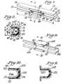
- FIGURE 1is a perspective view'of a reinforced bumper illustrating the position of an arched mid-span reinforcement shell.
- FIGURE 2is a cross section along lines 2-2 of FIGURE 1.
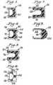
- FIGURE 3is a cross-section of another embodiment of the present invention illustrating a D-shaped reinforcement shell disposed in the cavity of a hollow bumper section and separated form the bumper section by a layer of structural foam.
- FIGURE 4is a cross-section of another embodiment of the present invention illustrating a reinforcement shell having a D-shaped configuration; the reinforcement shell is disposed in the cavity of a hollow bumper section having a double arch with an intervening layer of structural foam.
- FIGURE 5is a cross-section of another embodiment of the present invention illustrating a localized arch-shaped reinforcement disposed in the channel of a bumper section with an intervening layer of structural foam.
- FIGURE 6is a cross-section of another embodiment of the present invention illustrating a D-shaped reinforcement shell disposed in a rectangular bumper section and separated by segmented regions of structural foam.
- FIGURE 7is a cross-section of another embodiment of the present invention illustrating a an arch-shaped bumper having a rectangular reinforcement shell disposed thereon as a cap with an intervening layer of structural foam.
- FIGURE 8is a cross-section of a double-arch bumper section with an arch-shaped reinforcement cap.
- FIGURE 9is a perspective view of a reinforced door beam illustrating the position of a rectangular midspan reinforcement shell.
- FIGURE 10is a cross-section along lines 10-10 of FIGURE 9.
- FIGURE 11is a cross-section of another embodiment of the present invention illustrating an arched door beam with an arched reinforcement shell with an intervening layer of structural foam.
- reinforced automotive bumper 20is shown having bumper section 22 in the nature of longitudinal, channel-defining structure having a length substantially greater than its width.
- Each edge of vertical planar wall 24is bounded by sides 26.
- Each side 26has a flange 28 that extends over open channel 30.
- Wall 24defines an exterior surface or compression face 32 and a channel-side face or interior surface 34. It will be appreciated by those skilled in the art that compression face 32 receives the impact in a collision and is thus the region at which bending is induced.
- reinforcement shell assembly 40Positioned at the mid-span of bumper section 22, that is, generally centrally located between ends 36 and 38, reinforcement shell assembly 40 is seen having arched reinforcement shell 42 and intervening foam layer 44. If the location of maximum deformation is not at the central location, the reinforcement shell assembly will be appropriately off-center at the location of maximum deformation.
- Arched shell 42has a pair of flanges 45 which overlay and contact flanges 28 of bumper section 22.
- Arched shellhas arch portion 46 which extends in the direction of wall 38 of bumper section 22.
- arch shaped surface or a double or twin arch shaped surface or an apex shaped surface or a double or twin apex shaped surfaceare used to define not only a traditional U arch shape but also a D-shape, an example of which will be more fully illustrated hereinafter and M or V or W shapes.
- the structural member and the reinforcement shellmay be metal stampings or may be roll formed metal.
- Arched shellhas surface 48 which is in contact with and bonded to foam layer 44.
- arch portion 46 of shell 42extends in the direction of wall 38 and thus extends toward compression face 32 of bumper section 22.
- Foam layer 44is also in contact with and bonded to face 34 of wall 38 as well as to side wall inner surfaces 50, thereby attaching shell 42 rigidly to bumper section 22, forming a trilaminate construction.
- flanges 45are attached to flanges 28 by mig welds, although other means of attachment such as mechanical fasteners or high-strength adhesive may be suitable in a particular application.
- the length "L” of arched shell subassembly 40is preferably equal to or less than one third of the length "L" of bumper section 22.
- the width "W” of channel 52 defined by arch portion 46 of shell 42is preferably at least 75% of width "W"' of channel 30 of bumper section 22.
- the depth “D” of shell 42 which extends into channel 30is preferably at least 75% of the depth "D” of channel 30.
- Bell-shaped, stilted arches or D-shapes having a rise (D) to span (W) ratio of from about .5:1 .0 to about 1.0:1 .0are most preferred.
- shell 42is a relatively thin gauge metal compared to that of bumper section 22.
- the metal used to form shell 42 and section 22will typically be steel or aluminum.
- DI-form 140 steel between 0.8 and 1 .4 mmis particularly preferred for shell 42.
- metalis preferred, other materials such as plastic may be appropriate in a given application.
- One of the advantages of the present inventionis the ability to use are relatively low-strength steel for bumper section 22 while reinforcing the structure with a light-weight, thin, high-strength steel shell 42.
- Foam 44is preferably a resin-based material which incorporates hollow glass microspheres to reduce density.
- the density of the materialshould preferably be from about 320.37 kgm 3 (20 pounds per cubic feet) to about 640.74 kgm 3 (40 pounds per cubic feet) to minimize weight.
- the melting point, heat distortion temperature and the temperature at which chemical breakdown occursmust also be sufficiently high such that foam layer 44 maintains its structure at high temperatures typically encountered in paint ovens and the like. Therefore, foam 44 should be able to withstand temperatures in excess of 200 degrees C. and preferably 175 degrees C. for short times.
- Foam layer 4has a thickness of preferably about 2 to 8 mm around the arch.
- foam layer 44includes a synthetic resin, glass microspheres, a blowing agent and a filter.
- Foam 44is preferably expanded in place between shell 42 and section 22 and is prepared by blending together the following materials.
- a synthetic resincomprises from about 50 percent to about 80 percent by weight and more preferably from about 60 percent to about 75 percent by weight of the mixture used to form foam 44.
- Glass microspherescomprises from about 10 to about 40 percent by weight and more preferably from about 15 to about 25 percent by weight of the mixture.
- a blowing agentcomprises from about 1 to about 10 percent by weight and more preferably from about 2 to about 6 percent by weight of the mixture.
- Layer 44could be initially applied in unexpanded form to either shell 42 or section 22 and then expanded into intimate contact with the other member and thereby bonded to both members 22 and 42. Where the foam is heat expandable and the structural member is a vehicle part, use could be made of the paint oven to initiate expansion of the foam, without requiring a separate heating step.
- a fillercomprises from about 1 percent to about 10 percent by weight and preferably from about 3 percent to about 8 percent by weight of the mixture used to form foam 44.
- thermosetssuch as epoxy resins, vinyl ester resins, thermoset polyester resins, and urethane resins. It is not intended that the scope of the present invention be limited by molecular weight of the resin and suitable weights will be understood by those skilled in the art based on the present disclosure.
- various acceleratorssuch as imidizoles and "DMP 30", and curing agents, preferably di-cyanamide, may also be included to enhance the cure rate.
- a functional amount of acceleratoris typically from about 1 percent to about 3 percent of the resin weight with a corresponding reduction in resin, microspheres or filler.
- the amount of curing agent usedis typically from about 2 percent to about 8 percent of the resin weight with a corresponding reduction in resin, microspheres or filler.
- Effective amounts of processing aids, stabilizers, colorants, UV absorbers and the likemay also be included in layer.
- Thermoplasticsmay also be suitable in some applications.
- the present inventionprovides a number of other configurations which embody the inventive concepts of the present invention as a motor vehicle bumper. More specifically, and referring now to Figure 3 of the drawings, structural member or main bumper section 54 is shown having flanges 56 that are welded to local reinforcement shell 58. Structural foam 60 is shown bonding shell 58 in place in the channel defined by bumper section 54. In Figure 4, bumper section 62 has a double arch portion 64 having twin arches 66 and 68. Structural foam layer 70 is disposed in the channel defined by section 62. As with the structure described in Figure 4, shell 72 is D-shaped and is attached to flanges 74.
- shell 76 having a stilted arch configurationis utilized in combination with a double arch main bumper section 78.
- Shell 76has a pair of flanges 80 that are attached to corresponding flanges 82 of bumper section 78.
- Figure 6is a modification of the structure depicted in Figure 3, with the foam layer being segmented, i.e. provided as separate spaced linear rows or ribbon 84.
- reinforcement shell 86forms an external cap on bumper section 88.
- Bumper section 88has the stilted arch configuration and is provided with flanges 90 that are attached to ends 92 of shell 86.
- Foam layer 94is seen in the channel defined by shell 86.
- bumper section 94has double arch structure 96 and is separated from arched reinforcement shell or cap 98 by foam layer 100.
- door side impact beam 102is shown generally having beam section 104 defining arch 106.
- reinforcement cap or shell 108is provided and is attached (preferably by spot welding) to beam section 104 at flanges 110 and 112.
- An intervening layer of foamis disposed between inner surface 114 of cap 108 and outer surface 116 of beam 104.
- the cap and beam sectioncould be reversed; that is, part 108 could be the beam and part 104 an internal cap. It is to be understood that this reversal could be achieved in all of the preferred designs, including those described in connection with the bumper.
- FIG. 11 of the drawingsstill another configuration is shown in which two complementary arches are nested one within the other.
- Part 118can form either the cap or the main beam body with part 120 forming the corresponding shell or beam.
- Foam 122is shown disposed between parts 118 and 120 in the manner previously described.
- the present inventionprovides a method of reinforcing a structural part which includes the steps of forming a layer of structural foam at a local reinforcement site in a channel-shaped structural member.
- a reinforcement shellis placed at the midspan of the channel-shaped member and preferably extends no more than one-third the length of the channel-shaped member.
- the structural foamis placed on one surface of the shell which then contacts and bonds to the channel-shaped member.
- the inventionhas been described primarily in connection with vehicle parts, it is to be understood that the invention may be practiced as part of other products, such as aircrafts, ships, bicycles or virtually anything that requires energy for movement. Similarly, the invention may be used with stationary or static structures, such as buildings, to provide a rigid support when subjected to vibration such as from an earthquake or simply to provide a lightweight support for structures subjected to loads. Additionally, while the invention has been described primarily with respect to heat expandable foams and with respect to metal parts such as the structural member and shell, other materials can be used. For example, the foam could be any suitable known expandable foam which is chemically activated into expansion and forms a rigid structural foam.
- the shellcould be made of materials other than metal such as various plastics or polymeric materials or various wood type fibrous materials having sufficient rigidity to function as a back drop or support for the foam.
- a heat expandable foamis used the support or backdrop should be able to withstand the heat encountered during the heat curing.
- foam materialsare used, however, it is not necessary that the support member be able to withstand high temperatures. Instead, the basic requirement for the support member is that it have sufficient rigidity to function in its intended manner. It is also possible, for example, to use as the shell materials which in themselves become rigid upon curing or further treatment.
- the inventionmay also be practiced where the structural member is made of materials other than metal. It is preferred, however, that materials be selected for the structural member and shell as well as the foam so that the thin unexpanded foam upon expansion forms a strong bond with these members so that a structural composition will result.
Landscapes
- Engineering & Computer Science (AREA)
- Mechanical Engineering (AREA)
- Architecture (AREA)
- Structural Engineering (AREA)
- Chemical & Material Sciences (AREA)
- Combustion & Propulsion (AREA)
- Transportation (AREA)
- General Engineering & Computer Science (AREA)
- Body Structure For Vehicles (AREA)
- Rod-Shaped Construction Members (AREA)
- Laminated Bodies (AREA)
- Joining Of Building Structures In Genera (AREA)
Description
- The present invention relates generally to methods and apparatus for reinforcingstructural members and, more specifically, relates to local reinforcement of channel-shapedsections subject to bending.
- In a number of applications, particularly in the automotive industry, there is aneed for light-weight, high-strength structural members. Although structural membershaving these characteristics can be readily obtained through the use of various metalalloys such as titanium alloys and the like, light-weight, high-strength alloys are generallycost prohibitive in automotive applications where weight reductions are closely balancedagainst the cost of materials. Moreover, reinforcement techniques are required which canbe readily adapted to existing geometries of structural parts, thereby eliminating the needfor fundamental design changes and providing a means by which substandard designperformance can be remedied. That is, in many instances design deficiencies arediscovered after vehicle design has reached the stage at which radical changes are nolonger feasible.
- In addition, a significant amount of emphasis has been placed on the performance characteristics of channel-shaped structural components which encounter forces thatproduce bending. For example, many side impact beams designed for motor vehicledoors have a channel-shaped cavity. In addition, many functional bumpers are channel-shaped.These channel-shaped sections are most susceptible to bending forces whichoriginate at or concentrate in the midspan of the beam.
- Although filling the entire section with plastic foam does significantly increasesection stiffness (at least when high-density foams are utilized), this technique may alsosignificantly increase mass and thus part weight, which, as stated, is undesirable in mostapplications. In addition, filling a section entirely with foam can contribute significantlyto cost. Finally, a large foam core often creates an unwanted heat sink. And, althoughincreasing the metal gauge of a section or adding localized metal reinforcements willincrease stiffness, as the metal thickness increases, it becomes more difficult to form thepart due to limitations of metal forming machines.
- A number of approaches have been proposed for dealing with the problem ofreinforcing channel-shaped sections subjected to bending as alternatives to high-costalloys, thick-metal sections and large foam cores. For example, a side impact beam fora vehicle door has been proposed which comprises an open channel-shaped metalmember having a longitudinal cavity which is filled with a thermoset or thermoplasticresin-base core. The core is disposed in the midspan of the beam. The core may includehollow glass microspheres in order to decrease density and thus weight.
- A reinforcement insert comprising a precast reinforcement has been proposed.
- The reinforcement is formed of a plurality of pellets containing a thermosetresin and a blowing agent. The precast member is expanded and cured in place in astructural member. A composite tubular door beam reinforced with a syntactic foamcore localized at the midspan of the tube has also been described in the art. Theresin-based core occupies not more than one-third of the bore of the tube.
- Tube-in-tube structures having high stiffness-to-mass ratios have also beenproposed in which two nested tubes have a layer of foam disposed in the annulusbetween the tubes. A local reinforcement in the nature of a foamable resin disposedon a drop-in carrier has also been described. The carrier is placed in the channel ofa hollow structural member following which the resin is expanded.
- GB 2197267 discloses a bumper for a motor vehicle in which an energyabsorbent foam is held against the bumper panelling.
- US 5575526 discloses a reinforced structural member for a vehicle,comprising, a structural member defining an open or closed channel having acompression face;
- a reinforcement shell having a length less than the length of saidchannel;
- said reinforcement shell and said structural member beinginterconnected;
- a layer of structural foam disposed between a portion of said structuralmember and a portion of said reinforcement shell to define a trilaminate region, saidlayer of structural foam being bonded to, said structural member and to saidreinforcement shell. The laminate beam for a radiator support comprises a structuralmember defining an open channel and a reinforcement shell which are interconnectedby a layer of structural foam which is bonded to said structural member and thereinforcement shell.
- To reinforce the structural member the reinforcement shell, which is ofsubstantially the same size as the structural member, is placed inside the openchannel and bonded to the structural member.
- Accordingly, it would be desirable to provide a low-cost technique for reinforcinga channel-shaped section subjected to bending without significantly increasing the mass.It would also be desirable to provide a method of reinforcing an existing channel-shapedsection which does not require any fundamental design change to the member. Thepresent invention provides hollow sections which have increased strength with moderateincreases in mass, all without the use of high volumes of expensive resins. The presentinvention further provides a method for reinforcing existing structural parts withoutredesigning the geometry of the part It has been found that the present inventionincreases section stiffness and strength in channel-shaped sections in a highly efficientmanner.
- According to a first aspect of the present invention there is provided areinforced structural member for a vehicle, comprising,
- a structural member defining an open or closed channel having a compression face;
- a reinforcement shell having a length less than the length of said channel;
- said reinforcement shell and said structural member being interconnected;
- a layer of structural foam disposed between a portion of said structuralmember and a portion of said reinforcement shell to define a trilaminate region,said layer of structural foam being bonded to said structural member and to saidreinforcement shell; characterised in that said reinforcement shell is no greaterthan one third of the length of the structural member and is disposed at a locationof maximum deformation on the structural member which is the region at whichbending is induced in a collision;
- said trilaminate region having an arch shaped surface or a double or twinarch shaped surface or an apex shaped surface or a double or a twin apex shapedsurface and said arch or apex projects in the direction of the compression face ofthe channel.
- In one embodiment the present invnetion provides a reinforced channel-shaped memberhaving a thin, local reinforcement shell separated from the channel-shaped member bya layer of structural foam. At the reinforced section an arch extends in a directionopposite that of the force to which the member is subjected; that is, the arch projects inthe direction of the compression face of the channel-shaped member. The arch may bepresent as the channel-shaped member, the reinforcement shell or both the channel-shapedmember and the shell. A portion of the shell preferably contacts the channel-shapedmember and is attached thereto by a spot weld or other means of attachment. Thecombination of the arch and the structural foam supports the load, stabilizes the walls ofthe channel-shaped member and distributes force over a generalized area away fromconcentration points at the welds. In one aspect, the reinforcement shell and the structuralfoam are preferably limited to no greater than about one third of the length of thechannel-shaped member and are disposed substantially at the midspan of the channel-shapedmember. In one aspect, the shell is disposed in the channel of the channel-shapedmember and in another the shell forms a cap on the exterior of the channel-shapedmember. The shell is preferably high-strength steel which allows low-strength steel to beused as the structural member. Also, in applications in which the main structural memberis high-strength steel, the shell may comprise a mild steel or aluminum.
- According to a further aspect of the present invention there is provided amethod of reinforcing a structural member defining an open or closed channelhaving a compression face, which is the face which receives the impact in acollision, for a vehicle comprising:
placing a reinforcement shell that is no greater than one-third the length ofthe structural member at a location of maximum deformation on the structuralmember which is the region at which bending is induced in a collision and bondingit thereto with a structural foam to create a trilaminate region having an archshaped surface or a double or a twin arch shaped surface or an apex shaped surfaceor a double or a twin apex shaped surface and said arch or apex projects in thedirection of the compression face of the channel. - In one embodiment the present invention provides a method of reinforcinga structural part which includes the steps of forming a layer of structural foam ata local reinforcement site in a channel-shaped structural member. A reinforcementshell is placed at the midspan of the channel-shaped member and extends no morethan one-third the length of the channel-shaped member. The structural foam isplaced on one surface of the shell which then contacts and bonds to the channel-shapedmember.
- These and other advantages and objects of the present invention will now be morefully described with reference to the drawings.
- FIGURE 1 is a perspective view'of a reinforced bumper illustrating the positionof an arched mid-span reinforcement shell.
- FIGURE 2 is a cross section along lines 2-2 of FIGURE 1.
- FIGURE 3 is a cross-section of another embodiment of the present inventionillustrating a D-shaped reinforcement shell disposed in the cavity of a hollow bumpersection and separated form the bumper section by a layer of structural foam.
- FIGURE 4 is a cross-section of another embodiment of the present inventionillustrating a reinforcement shell having a D-shaped configuration; the reinforcementshell is disposed in the cavity of a hollow bumper section having a double arch with anintervening layer of structural foam.
- FIGURE 5 is a cross-section of another embodiment of the present inventionillustrating a localized arch-shaped reinforcement disposed in the channel of a bumpersection with an intervening layer of structural foam.
- FIGURE 6 is a cross-section of another embodiment of the present inventionillustrating a D-shaped reinforcement shell disposed in a rectangular bumper section andseparated by segmented regions of structural foam.
- FIGURE 7 is a cross-section of another embodiment of the present inventionillustrating a an arch-shaped bumper having a rectangular reinforcement shell disposedthereon as a cap with an intervening layer of structural foam.
- FIGURE 8 is a cross-section of a double-arch bumper section with an arch-shapedreinforcement cap.
- FIGURE 9 is a perspective view of a reinforced door beam illustrating theposition of a rectangular midspan reinforcement shell.
- FIGURE 10 is a cross-section along lines 10-10 of FIGURE 9.
- FIGURE 11 is a cross-section of another embodiment of the present inventionillustrating an arched door beam with an arched reinforcement shell with an interveninglayer of structural foam.
- Referring now to Figure 1 of the drawings, reinforced
automotive bumper 20 isshown havingbumper section 22 in the nature of longitudinal, channel-defining structurehaving a length substantially greater than its width. Each edge of verticalplanar wall 24is bounded bysides 26. Eachside 26 has aflange 28 that extends overopen channel 30.Wall 24 defines an exterior surface orcompression face 32 and a channel-side face orinterior surface 34. It will be appreciated by those skilled in the art thatcompression face 32 receives the impact in a collision and is thus the region at which bending is induced. - Positioned at the mid-span of
bumper section 22, that is, generally centrallylocated between ends 36 and 38,reinforcement shell assembly 40 is seen havingarched reinforcement shell 42 and interveningfoam layer 44. If the location ofmaximum deformation is not at the central location, the reinforcement shell assemblywill be appropriately off-center at the location of maximum deformation.Archedshell 42 has a pair offlanges 45 which overlay andcontact flanges 28 ofbumpersection 22. Arched shell hasarch portion 46 which extends in the direction ofwall 38 ofbumper section 22. For the purposes of this application the terms arch shapedsurface or a double or twin arch shaped surface or an apex shaped surface or a doubleor twin apex shaped surface are used to define not only a traditional U arch shape butalso a D-shape, an example of which will be more fully illustrated hereinafter and Mor V or W shapes. - The structural member and the reinforcement shell may be metal stampings ormay be roll formed metal.
- Referring now to Figure 2 of the drawings, the relationship of
arched shellsubassembly 40 andbumper section 22 is more clearly shown. Arched shell hassurface 48 which is in contact with and bonded tofoam layer 44. Again,arch portion 46 ofshell 42 extends in the direction ofwall 38 and thus extends towardcompression face 32 ofbumper section 22.Foam layer 44 is also in contact with and bonded to face 34 ofwall 38 as well as to side wallinner surfaces 50, thereby attachingshell 42 rigidly tobumpersection 22, forming a trilaminate construction. In addition,flanges 45 are attached toflanges 28 by mig welds, although other means of attachment such as mechanical fastenersor high-strength adhesive may be suitable in a particular application. - The length "L" of
arched shell subassembly 40 is preferably equal to or less thanone third of the length "L" ofbumper section 22. The width "W" of channel 52 definedbyarch portion 46 ofshell 42 is preferably at least 75% of width "W"' ofchannel 30 ofbumper section 22. The depth "D" ofshell 42 which extends intochannel 30 is preferablyat least 75% of the depth "D" ofchannel 30. Bell-shaped, stilted arches or D-shapeshaving a rise (D) to span (W) ratio of from about .5:1 .0 to about 1.0:1 .0 are mostpreferred. - As best illustrated in Figure 2 of the drawings,
shell 42 is a relatively thin gaugemetal compared to that ofbumper section 22. The metal used to formshell 42 andsection 22 will typically be steel or aluminum. For example DI-form 140 steel between 0.8 and1 .4 mm is particularly preferred forshell 42. (And note that while metal is preferred,other materials such as plastic may be appropriate in a given application). One of theadvantages of the present invention is the ability to use are relatively low-strength steelforbumper section 22 while reinforcing the structure with a light-weight, thin, high-strengthsteel shell 42. By providing an arch 46 in the direction ofcompression face 32;an intervening layer ofadhesive foam 44 which is bonded to shell 42 and tosection 22;and spot welding (or otherwise attaching)shell 42 tosection 22, reinforcedbumper 20provides maximum resistance to bending with minimal weight and cost. The combinationofarch 46 andfoam 44 in compression reinforcesbumper section 22 for a substantialreduction in buckling. It is to be understood thatfoam layer 44 covers substantially allofsurface 48 ofshell 42. Foam 44 is preferably a resin-based material which incorporates hollow glassmicrospheres to reduce density. With specific reference now to the composition offoamlayer 44, the density of the material should preferably be from about 320.37 kgm3 (20 pounds per cubicfeet) to about 640.74 kgm3 (40 pounds per cubic feet) to minimize weight. Themelting point, heat distortion temperature and the temperature at which chemical breakdown occurs mustalso be sufficiently high such thatfoam layer 44 maintains its structure at hightemperatures typically encountered in paint ovens and the like. Therefore,foam 44 shouldbe able to withstand temperatures in excess of 200 degrees C. and preferably 175 degreesC. for short times. Foam layer 4 has a thickness of preferably about 2 to 8 mm around thearch.- In one particularly preferred
embodiment foam layer 44 includes a syntheticresin, glass microspheres, a blowing agent and a filter.Foam 44 is preferably expanded inplace betweenshell 42 andsection 22 and is prepared by blending together the followingmaterials. A synthetic resin comprises from about 50 percent to about 80 percent byweight and more preferably from about 60 percent to about 75 percent by weight of themixture used to formfoam 44. Glass microspheres comprises from about 10 to about 40percent by weight and more preferably from about 15 to about 25 percent by weight ofthe mixture. A blowing agent comprises from about 1 to about 10 percent by weight andmore preferably from about 2 to about 6 percent by weight of the mixture. Layer 44 could be initially applied in unexpanded form to either shell 42 orsection 22 and then expanded into intimate contact with the other member and thereby bonded to bothmembers - Various fillers (such as fumed silica, calcium carbonate, milled glass fiber, andchopped glass strand) may be included. A filler comprises from about 1 percent to about10 percent by weight and preferably from about 3 percent to about 8 percent by weightof the mixture used to form
foam 44. - Preferred synthetic resins for use in the present invention include thermosets suchas epoxy resins, vinyl ester resins, thermoset polyester resins, and urethane resins. It isnot intended that the scope of the present invention be limited by molecular weight of theresin and suitable weights will be understood by those skilled in the art based on thepresent disclosure. Where the resin is a thermoset resin, various accelerators, such asimidizoles and "
DMP 30", and curing agents, preferably di-cyanamide, may also beincluded to enhance the cure rate. A functional amount of accelerator is typically fromabout 1 percent to about 3 percent of the resin weight with a corresponding reduction inresin, microspheres or filler. Similarly, the amount of curing agent used is typically fromabout 2 percent to about 8 percent of the resin weight with a corresponding reduction inresin, microspheres or filler. Effective amounts of processing aids, stabilizers, colorants,UV absorbers and the like may also be included in layer. Thermoplastics may also besuitable in some applications. - In the following tables, preferred formulations for use in forming
foam 44 are described. All percentages in the present disclosure are percent by weight unlessotherwise specifically designated.INGREDIENT PERCENT BY WEIGHT FORMULA 1 One Part Bisphenol A Epoxy 70% Nipol (RTM) Liquid Rubber 8% Di-cy (RTM) Curative 7% EMI-24 (RTM) Accelerator 1% B38 Microspheres (RTM) 14% FORMULA II Two Part Resin Side "A" Curative Side "B" Epoxy Resin 74% Aliphatic Amine 65% Celogen (RTM) Blowing Agent 6% Thixotrope 8% Thixotrope 4% K20 Microspheres (RTM) 27% K20 Microspheres (RTM) 16% - In addition to the structure illustrated in Figures 1 and 2 of the drawings, thepresent invention provides a number of other configurations which embody the inventiveconcepts of the present invention as a motor vehicle bumper. More specifically, andreferring now to Figure 3 of the drawings, structural member or
main bumper section 54is shown havingflanges 56 that are welded tolocal reinforcement shell 58.Structuralfoam 60 is shown bondingshell 58 in place in the channel defined bybumper section 54.In Figure 4,bumper section 62 has a doublearch portion 64 havingtwin arches Structural foam layer 70 is disposed in the channel defined bysection 62. As with the structure described in Figure 4,shell 72 is D-shaped and is attached to flanges 74. InFigure 5, shell 76 having a stilted arch configuration is utilized in combination with adouble archmain bumper section 78.Shell 76 has a pair offlanges 80 that are attachedto correspondingflanges 82 ofbumper section 78. Figure 6 is a modification of thestructure depicted in Figure 3, with the foam layer being segmented, i.e. provided asseparate spaced linear rows orribbon 84. - Referring now to Figure 7 of the drawings,
reinforcement shell 86 forms anexternal cap onbumper section 88.Bumper section 88 has the stilted arch configurationand is provided withflanges 90 that are attached to ends 92 ofshell 86.Foam layer 94is seen in the channel defined byshell 86. In Figure 8,bumper section 94 has doublearchstructure 96 and is separated from arched reinforcement shell orcap 98 byfoam layer 100. - In addition to reinforced bumpers, the present invention is useful in reinforcingdoor side beams. Referring now to Figure 9 of the drawings, door
side impact beam 102is shown generally havingbeam section 104 definingarch 106. As seen in Figures 9 and10, reinforcement cap orshell 108 is provided and is attached (preferably by spotwelding) tobeam section 104 atflanges inner surface 114 ofcap 108 andouter surface 116 ofbeam 104.Alternatively, the cap and beam section could be reversed; that is,part 108 could be thebeam andpart 104 an internal cap. It is to be understood that this reversal could beachieved in all of the preferred designs, including those described in connection with the bumper. In Figure 11 of the drawings still another configuration is shown in which twocomplementary arches are nested one within the other.Part 118 can form either the capor the main beam body withpart 120 forming the corresponding shell or beam.Foam 122is shown disposed betweenparts - In still another aspect the present invention provides a method of reinforcing astructural part which includes the steps of forming a layer of structural foam at a localreinforcement site in a channel-shaped structural member. A reinforcement shell is placedat the midspan of the channel-shaped member and preferably extends no more than one-thirdthe length of the channel-shaped member. The structural foam is placed on onesurface of the shell which then contacts and bonds to the channel-shaped member.
- While the invention has been described primarily in connection with vehicleparts, it is to be understood that the invention may be practiced as part of other products,such as aircrafts, ships, bicycles or virtually anything that requires energy for movement.Similarly, the invention may be used with stationary or static structures, such asbuildings, to provide a rigid support when subjected to vibration such as from anearthquake or simply to provide a lightweight support for structures subjected to loads.Additionally, while the invention has been described primarily with respect to heatexpandable foams and with respect to metal parts such as the structural member and shell,other materials can be used. For example, the foam could be any suitable knownexpandable foam which is chemically activated into expansion and forms a rigidstructural foam. The shell could be made of materials other than metal such as various plastics or polymeric materials or various wood type fibrous materials having sufficientrigidity to function as a back drop or support for the foam. Where a heat expandable foamis used the support or backdrop should be able to withstand the heat encountered duringthe heat curing. Where other types of foam materials are used, however, it is notnecessary that the support member be able to withstand high temperatures. Instead, thebasic requirement for the support member is that it have sufficient rigidity to function inits intended manner. It is also possible, for example, to use as the shell materials whichin themselves become rigid upon curing or further treatment. The invention may also bepracticed where the structural member is made of materials other than metal. It ispreferred, however, that materials be selected for the structural member and shell as wellas the foam so that the thin unexpanded foam upon expansion forms a strong bond withthese members so that a structural composition will result.
Claims (32)
- A reinforced structural member (20;102) for a vehicle comprising,a structural member (22;104) defining an open or closed channel havinga compression face (32) which is the face which receives the impact in a collision;a reinforcement shell (40;108) having a length (L) less than the length (L')of said channel (30);said reinforcement shell (40;108) and said structural member (22;104) beinginterconnected;a layer of structural foam (44) disposed between a portion of said structuralmember (22;104) and a portion of said reinforcement shell (40;108) to define atrilaminate region, said layer of structural foam (44) being bonded to said structuralmember (22;104) and to said reinforcement shell; characterised in that saidreinforcement shell (40;108) is no greater than one third of the length of thestructural member (22;104) and is disposed at a location of maximum deformationon the structural member (22;104) which is the region at which bending is inducedin a collision;said trilaminate region having an arch shaped surface or a double or twinarch shaped surface or an apex shaped surface or a double or a twin apex shapedsurface and said arch or apex projects in the direction of the compression face (32)of the channel.
- The reinforced structural member (20;102) recited in claim 1, wherein:
said trilaminate region having an apex-shaped surface or a double or twinapex shaped surface is a M, V or W shaped surface. - The reinforced structural member (20;102) recited in claim 1 or 2,wherein said reinforcement shell (40; 108) is the arch-shaped surface or the doublearch- shaped or the twin arch-shaped surface or the apex-shaped surface or thedouble or twin apex-shaped surface.
- The reinforced structural member (20; 102) recited in claim 1 or 2,wherein said structural member (22; 104) is the arch-shaped surface or the doublearch- shaped or the twin arch shaped surface or the apex-shaped surface or thedouble or twin apex shaped surface.
- The reinforced structural member (20; 102) recited in claim 1 or 2, wherein said reinforcement shell (40; 108) is the arch-shaped surface or the doublearch- shaped or twin arch shaped surface or the apex-shaped surface, or the doubleor the twin apex-shaped surface and said structural member (22; 104) is the arch-shapedsurface or the double arch-shaped or twin arch shaped surface or the apex-shapedsurface or a double or twin apex shaped surface.
- The reinforced structural member (20; 102) recited in any of thepreceding claims, wherein said reinforcement shell (40; 108) is nested in saidchannel (30) of said structural member (22; 104).
- The reinforced structural member (20; 102) recited in any of claims 1to 5, wherein said structural member (22; 104) has an interior surface (34) definingchannel (30) and an exterior surface (32) and wherein said structural foam layer(44) is disposed between said reinforcement shell (40; 108) and said exteriorsurface (32).
- The reinforced structural member (20; 102) recited in any of thepreceding claims, wherein the width "w" of the channel (52) defined by the archportion (46) of the shell (42) is at least 75% the width "w" of the channel (30)defined by the structural member (22), and/or the depth "D" of the shell (42) is atleast 75% the depth "D" of the channel (30) defined by the structural member.
- The reinforced structural member (20; 102) recited in claim 8 whereinthe arch is a bell-shaped arch, stilted arch or D-shaped arch and has a rise (D) tospan (w) ratio of from 0.5:1 to 1.0:1.0.
- The reinforced structural member (20; 102) recited in claim 1, whereinsaid reinforcement shell (40; 108) is positioned at a midspan of said structuralmember (22; 104).
- The reinforced structural member (20; 102) recited in any of thepreceding claims, wherein said structural foam (44) contains glass microspheres.
- The reinforced structural member (20; 102) recited in claim 3, whereinsaid reinforcement shell (40; 108) has a double arch shape.
- The reinforced structural member (20; 102) recited in claim 4, whereinsaid structural member has a double arch shape.
- The reinforced structural member (20; 102) recited in any of thepreceding claims, wherein said structural foam layer (44) has a thickness of from2 to 10mm.
- The reinforced structural member (20; 102) recited in any of thepreceding claims, wherein said structural member (22; 104) and said reinforcementshell (40; 108) are metal stampings or roll formed metal.
- The reinforced structural member (20; 102) recited in any of thepreceding claims, wherein said reinforcement shell (40; 108) is formed of high-strengthsteel or aluminum.
- The reinforced structural member (20; 102) recited in any of thepreceding claims, wherein said foam layer (44) is segmented.
- The reinforced structural member (20; 102) recited in any of thepreceding claims, wherein said structural foam (44) contains from 60 to 78 percentby weight polymer, from 10 to 30 percent by weight glass microspheres, from 3to 10 percent by weight filler and from 2 to 8 percent by weight blowing agent.
- The reinforced structural member (20; 102) recited in any of thepreceding claims, wherein said foam (44) is expandable.
- The reinforced structural member (20; 102) recited in claim 19, whereinsaid foam (44) is heat expandable.
- The reinforced structural member (20; 102) recited in any of thepreceding claims, wherein said structural member (22; 104) is a vehicle bumper.
- The reinforced structural member (20; 102) recited in any of thepreceding claims, wherein said structural member (22; 104) is a vehicle door sidebeam.
- A reinforcement shell for use in a reinforced structural memberaccording to anyone of claims 1 to 22.
- A method of reinforcing a structural member (22; 104) defining anopen or closed channel (30) having a compression face (32) which is the facewhich receives the impact in a collision for a vehicle comprising:
placing a reinforcement shell (40; 108) that is no greater than one-third thelength of the structural member (22; 104) at a location of maximum deformationon the structural member (20; 102) which is the region at which bending is induced in a collision and bonding it thereto with a structural foam (44) to createa trilaminate region having an arch shaped surface or a double or a twin archshaped surface or an apex shaped surface or a double or a twin apex shaped surfaceand said arch or apex projects in the direction of the compression face (32) of thechannel (30). - The method of claim 24 wherein the structural foam (44) is anexpandable foam, and the foam bonds the structural member (22; 104) and thereinforcement shell (40; 108) upon expansion of the foam (44).
- A method as claimed in claim 25 wherein the expandable structuralfoam (44) is provided on one or both of respective surfaces of the channel shapedstructural member (22; 104) and the reinforcement shell (40; 108) to be bondedtogether.
- The method of claim 24, 25 or 26 further comprising nesting thereinforcement shell (40; 108) in the channel-shaped structural member (22; 104).
- The method of claim 24, 25 or 26 further comprising mounting thereinforcement shell (40; 108) outside of and around the channel-shaped structuralmember (22; 104).
- The method of any of claims 24 to 28 wherein the structural member(22; 104) is a vehicle bumper.
- The method of any of claims 24 to 28 wherein the structural member(22; 104) is a vehicle door side beam.
- The method of any of claims 24 to 30 wherein the structural member(22, 104) is a vehicle part, and the foam (44) is expanded by heat activation.
- The method of claim 31 wherein the heat activation occurs in a paintoven.
Priority Applications (1)
| Application Number | Priority Date | Filing Date | Title |
|---|---|---|---|
| EP00203038AEP1057718A3 (en) | 1997-07-21 | 1998-07-21 | Reinforced structural members |
Applications Claiming Priority (4)
| Application Number | Priority Date | Filing Date | Title |
|---|---|---|---|
| US5305397P | 1997-07-21 | 1997-07-21 | |
| US53053P | 1997-07-21 | ||
| US103031 | 1998-06-23 | ||
| US09/103,031US6096403A (en) | 1997-07-21 | 1998-06-23 | Reinforced structural members |
Related Child Applications (1)
| Application Number | Title | Priority Date | Filing Date |
|---|---|---|---|
| EP00203038ADivisionEP1057718A3 (en) | 1997-07-21 | 1998-07-21 | Reinforced structural members |
Publications (2)
| Publication Number | Publication Date |
|---|---|
| EP0893331A1 EP0893331A1 (en) | 1999-01-27 |
| EP0893331B1true EP0893331B1 (en) | 2001-03-21 |
Family
ID=26731391
Family Applications (1)
| Application Number | Title | Priority Date | Filing Date |
|---|---|---|---|
| EP98305783AExpired - LifetimeEP0893331B1 (en) | 1997-07-21 | 1998-07-21 | Reinforced structural members |
Country Status (17)
| Country | Link |
|---|---|
| US (2) | US6096403A (en) |
| EP (1) | EP0893331B1 (en) |
| JP (1) | JPH11156977A (en) |
| KR (1) | KR19990013558A (en) |
| AR (1) | AR013238A1 (en) |
| AT (2) | ATE199863T1 (en) |
| AU (1) | AU7398298A (en) |
| BR (1) | BR9802476A (en) |
| CA (1) | CA2242317A1 (en) |
| DE (2) | DE29812843U1 (en) |
| ES (1) | ES2157114T3 (en) |
| FR (1) | FR2763113B1 (en) |
| GB (1) | GB2327387B (en) |
| IT (1) | IT1305568B1 (en) |
| NL (1) | NL1009641C2 (en) |
| PL (1) | PL327392A1 (en) |
| TR (1) | TR199801352A3 (en) |
Cited By (13)
| Publication number | Priority date | Publication date | Assignee | Title |
|---|---|---|---|---|
| US6358584B1 (en) | 1999-10-27 | 2002-03-19 | L&L Products | Tube reinforcement with deflecting wings and structural foam |
| US6383610B1 (en) | 1997-12-08 | 2002-05-07 | L&L Products, Inc. | Self-sealing partition |
| US6422575B1 (en) | 2000-03-14 | 2002-07-23 | L&L Products, Inc. | Expandable pre-formed plug |
| US6467834B1 (en) | 2000-02-11 | 2002-10-22 | L&L Products | Structural reinforcement system for automotive vehicles |
| US6471285B1 (en) | 2000-09-29 | 2002-10-29 | L&L Products, Inc. | Hydroform structural reinforcement system |
| US6474722B2 (en) | 2000-03-14 | 2002-11-05 | L&L Products | Structural reinforcement member for wheel well |
| US6474723B2 (en) | 2000-03-14 | 2002-11-05 | L&L Products, Inc. | Heat activated reinforcing sleeve |
| US6502821B2 (en) | 2001-05-16 | 2003-01-07 | L&L Products, Inc. | Automotive body panel damping system |
| US6634698B2 (en) | 2000-08-14 | 2003-10-21 | L&L Products, Inc. | Vibrational reduction system for automotive vehicles |
| US6668457B1 (en) | 1999-12-10 | 2003-12-30 | L&L Products, Inc. | Heat-activated structural foam reinforced hydroform |
| US7392929B1 (en) | 2004-07-26 | 2008-07-01 | Zephyros, Inc. | Weldable synthetic material |
| US7479246B2 (en) | 2004-06-21 | 2009-01-20 | Zephyros, Inc. | Overmoulding |
| US8236128B2 (en) | 2006-10-26 | 2012-08-07 | Zephyros, Inc. | Adhesive materials, adhesive parts formed therewith and their uses |
Families Citing this family (179)
| Publication number | Priority date | Publication date | Assignee | Title |
|---|---|---|---|---|
| SE9601246L (en)* | 1996-04-01 | 1997-10-02 | Plannja Hardtech Ab | Safety Beam |
| US6341467B1 (en) | 1996-05-10 | 2002-01-29 | Henkel Corporation | Internal reinforcement for hollow structural elements |
| US6270600B1 (en)* | 1996-07-03 | 2001-08-07 | Henkel Corporation | Reinforced channel-shaped structural member methods |
| SE9703859L (en)* | 1997-10-23 | 1998-11-30 | Ssab Hardtech Ab | Vehicle impact protection beam |
| US7455350B2 (en)* | 1997-12-19 | 2008-11-25 | Henkel Kgaa | Assembly for sound-proofing cavities |
| US6372334B1 (en) | 1998-03-30 | 2002-04-16 | Henkel Corporation | Reinforcement laminate |
| ZA991856B (en) | 1998-08-27 | 1999-09-22 | Henkel Corp | Storage-stable compositions useful for the production of structural foams. |
| US20040201255A1 (en)* | 1998-10-19 | 2004-10-14 | Martin Jonsson | Lightweight beam |
| DE19848516A1 (en)* | 1998-10-21 | 2000-04-27 | Bayer Ag | Hollow chamber lightweight component |
| US6131897A (en) | 1999-03-16 | 2000-10-17 | L & L Products, Inc. | Structural reinforcements |
| GB2349851A (en)* | 1999-05-10 | 2000-11-15 | Rover Group | Motor vehicle longitudinal chassis member |
| EP1052162A3 (en)* | 1999-05-10 | 2003-05-21 | Bayerische Motoren Werke Aktiengesellschaft | Motor vehicle assembly |
| KR200266242Y1 (en)* | 1999-06-10 | 2002-02-28 | 이계안 | door structure for a vehicle |
| KR20010049950A (en)* | 1999-08-05 | 2001-06-15 | 제임스 이. 미러 | Frame structure of vehicle body |
| USH2047H1 (en) | 1999-11-10 | 2002-09-03 | Henkel Corporation | Reinforcement laminate |
| DE19954647C2 (en)* | 1999-11-13 | 2003-12-11 | Benteler Werke Ag | Side impact beams |
| US6263635B1 (en) | 1999-12-10 | 2001-07-24 | L&L Products, Inc. | Tube reinforcement having displaceable modular components |
| FR2803899B1 (en)* | 2000-01-17 | 2002-04-05 | Ecia Equip Composants Ind Auto | STRUCTURAL ELEMENT COMPRISING A REINFORCING BODY AND RIBS AND MOTOR VEHICLE THEREOF |
| AU2001230965A1 (en)* | 2000-02-11 | 2001-08-20 | L And L Products, Inc. | Structural reinforcement system for automotive vehicles |
| US6321793B1 (en) | 2000-06-12 | 2001-11-27 | L&L Products | Bladder system for reinforcing a portion of a longitudinal structure |
| WO2002004240A1 (en)* | 2000-07-12 | 2002-01-17 | Shape Corporation | Roll-formed and stamped doorbeam |
| US6508035B1 (en)* | 2000-07-25 | 2003-01-21 | Alcoa Inc. | Ultra-lightweight thin sliding door for a vehicle |
| US6820923B1 (en) | 2000-08-03 | 2004-11-23 | L&L Products | Sound absorption system for automotive vehicles |
| DE10043880B4 (en)* | 2000-09-04 | 2006-02-23 | Benteler Ag | bumper |
| US6494525B1 (en)* | 2000-09-15 | 2002-12-17 | Sika Corporation | Side impact reinforcement |
| US6403222B1 (en) | 2000-09-22 | 2002-06-11 | Henkel Corporation | Wax-modified thermosettable compositions |
| US6561571B1 (en) | 2000-09-29 | 2003-05-13 | L&L Products, Inc. | Structurally enhanced attachment of a reinforcing member |
| US6419305B1 (en) | 2000-09-29 | 2002-07-16 | L&L Products, Inc. | Automotive pillar reinforcement system |
| US6451876B1 (en) | 2000-10-10 | 2002-09-17 | Henkel Corporation | Two component thermosettable compositions useful for producing structural reinforcing adhesives |
| US6378933B1 (en)* | 2000-11-06 | 2002-04-30 | Daimlerchrysler Corporation | Reinforced vehicle framing |
| KR100373987B1 (en)* | 2000-11-08 | 2003-02-26 | 한국과학기술원 | Impact beam for car door |
| US6585202B2 (en) | 2001-01-05 | 2003-07-01 | Daimlerchrysler Corporation | Multi-tiered carrier structure for a motor vehicle |
| DE10101649C1 (en)* | 2001-01-16 | 2002-08-29 | Daimler Chrysler Ag | Structural element reinforced with metal foam |
| GB0106911D0 (en)* | 2001-03-20 | 2001-05-09 | L & L Products | Structural foam |
| GB2375328A (en) | 2001-05-08 | 2002-11-13 | L & L Products | Reinforcing element for hollow structural member |
| DE10135903B4 (en)* | 2001-07-24 | 2007-02-22 | Benteler Automobiltechnik Gmbh | bumper |
| US6855652B2 (en) | 2001-08-24 | 2005-02-15 | L&L Products, Inc. | Structurally reinforced panels |
| US6729425B2 (en) | 2001-09-05 | 2004-05-04 | L&L Products, Inc. | Adjustable reinforced structural assembly and method of use therefor |
| US6668513B2 (en)* | 2001-09-12 | 2003-12-30 | Visteon Global Technologies, Inc. | Structural composite member formed of a metal and reinforced by a blow-molded member |
| US6786533B2 (en)* | 2001-09-24 | 2004-09-07 | L&L Products, Inc. | Structural reinforcement system having modular segmented characteristics |
| US6942262B2 (en)* | 2001-09-27 | 2005-09-13 | Shape Corporation | Tubular energy management system for absorbing impact energy |
| US6793274B2 (en) | 2001-11-14 | 2004-09-21 | L&L Products, Inc. | Automotive rail/frame energy management system |
| US7041355B2 (en)* | 2001-11-29 | 2006-05-09 | Dow Global Technologies Inc. | Structural reinforcement parts for automotive assembly |
| CA2472727C (en)* | 2002-01-22 | 2010-10-26 | Dow Global Technologies Inc. | Reinforced structural body and manufacturing method thereof |
| DE10213753A1 (en)* | 2002-03-26 | 2003-10-16 | Basf Ag | composite elements |
| US7318873B2 (en) | 2002-03-29 | 2008-01-15 | Zephyros, Inc. | Structurally reinforced members |
| CN100553929C (en)* | 2002-04-15 | 2009-10-28 | 陶氏环球技术公司 | Improved vehicle structural members and methods of making the same |
| US6969551B2 (en)* | 2002-04-17 | 2005-11-29 | L & L Products, Inc. | Method and assembly for fastening and reinforcing a structural member |
| US7169344B2 (en)* | 2002-04-26 | 2007-01-30 | L&L Products, Inc. | Method of reinforcing at least a portion of a structure |
| US7077460B2 (en) | 2002-04-30 | 2006-07-18 | L&L Products, Inc. | Reinforcement system utilizing a hollow carrier |
| GB0211287D0 (en)* | 2002-05-17 | 2002-06-26 | L & L Products Inc | Improved baffle precursors |
| GB0211268D0 (en)* | 2002-05-17 | 2002-06-26 | L & L Products Inc | Hole plugs |
| GB0211775D0 (en) | 2002-05-23 | 2002-07-03 | L & L Products Inc | Multi segment parts |
| US7635114B2 (en)* | 2002-06-18 | 2009-12-22 | Mfs, Llc | Rotationally molded, reinforced decorative fence post and method of making same |
| US6814374B2 (en)* | 2002-06-28 | 2004-11-09 | Delphi Technologies, Inc. | Steering column with foamed in-place structure |
| US6920693B2 (en)* | 2002-07-24 | 2005-07-26 | L&L Products, Inc. | Dynamic self-adjusting assembly for sealing, baffling or structural reinforcement |
| US7004536B2 (en)* | 2002-07-29 | 2006-02-28 | L&L Products, Inc. | Attachment system and method of forming same |
| US20040034982A1 (en)* | 2002-07-30 | 2004-02-26 | L&L Products, Inc. | System and method for sealing, baffling or reinforcing |
| US6923499B2 (en)* | 2002-08-06 | 2005-08-02 | L & L Products | Multiple material assembly for noise reduction |
| DE10237962A1 (en)* | 2002-08-20 | 2004-03-04 | Dr.Ing.H.C. F. Porsche Ag | Structure for a motor vehicle |
| JP4052566B2 (en)* | 2002-09-05 | 2008-02-27 | 本田技研工業株式会社 | Frame coupling structure and coupling method |
| US6883858B2 (en)* | 2002-09-10 | 2005-04-26 | L & L Products, Inc. | Structural reinforcement member and method of use therefor |
| DE10251207A1 (en)* | 2002-10-31 | 2004-05-19 | Voestalpine Motion Gmbh | Profile element for automobile body impact protection has closed rectangular profile cross-section with opposing side surfaces having stiffening profiles |
| US7105112B2 (en)* | 2002-11-05 | 2006-09-12 | L&L Products, Inc. | Lightweight member for reinforcing, sealing or baffling |
| US20040091666A1 (en)* | 2002-11-12 | 2004-05-13 | Roberts Ronald K. | Structural composite member |
| US6834913B2 (en)* | 2002-11-13 | 2004-12-28 | Visteon Global Technologies, Inc. | Structural composite air handling duct |
| BR0317202B1 (en)* | 2002-12-27 | 2014-08-19 | Dow Global Technologies Inc | Expandable adhesive, foam insert, reinforced carrier structure and method for preparing a structural foam insert |
| GB0300159D0 (en)* | 2003-01-06 | 2003-02-05 | L & L Products Inc | Improved reinforcing members |
| US7313865B2 (en) | 2003-01-28 | 2008-01-01 | Zephyros, Inc. | Process of forming a baffling, sealing or reinforcement member with thermoset carrier member |
| DE10307637A1 (en)* | 2003-02-22 | 2004-09-09 | Benteler Automobiltechnik Gmbh | Cross-beam for vehicle bumper comprises C-profile made from magnesium or magnesium alloy whose arms are attached to deformation components and whose wall thickness is less than that of its base |
| WO2004076769A2 (en)* | 2003-02-24 | 2004-09-10 | Bell Helicopter Textron Inc. | Contact stiffeners for structural skins |
| WO2004078451A1 (en)* | 2003-03-05 | 2004-09-16 | Dow Global Technologies Inc. | Structural reinforcement article and process for prepareation thereof |
| US7478827B2 (en)* | 2003-03-06 | 2009-01-20 | Ford Global Technologies, Llc | Laminated backing for containing fragments of a fractured trim cover during deployment of a passenger restraint |
| US7055886B2 (en)* | 2003-03-28 | 2006-06-06 | Shape Corporation | Low-profile high-strength vehicle door beam |
| USD481549S1 (en)* | 2003-03-28 | 2003-11-04 | Cocso Management, Inc. | Chair frame portion |
| US6942910B2 (en)* | 2003-04-02 | 2005-09-13 | Visteon Global Technologies, Inc. | Structural hybrid beam utilizing an extruded profile |
| EP1468855A3 (en)* | 2003-04-11 | 2006-04-26 | HONDA MOTOR CO., Ltd. | Door for a vehicle |
| US7111899B2 (en) | 2003-04-23 | 2006-09-26 | L & L Products, Inc. | Structural reinforcement member and method of use therefor |
| GB2401349A (en) | 2003-05-08 | 2004-11-10 | L & L Products | Reinforcement for a vehicle panel |
| US7041193B2 (en)* | 2003-05-14 | 2006-05-09 | L & L Products, Inc. | Method of adhering members and an assembly formed thereby |
| WO2004109145A2 (en)* | 2003-06-05 | 2004-12-16 | Pedro Frommer, M.D., P.A. | Resilient and deformable member for absorbing kinetic energy |
| US7249415B2 (en)* | 2003-06-26 | 2007-07-31 | Zephyros, Inc. | Method of forming members for sealing or baffling |
| US7513564B2 (en)* | 2003-07-01 | 2009-04-07 | Honda Motor Co., Ltd. | Skeleton structural member for transportation equipment |
| US20070173553A1 (en)* | 2003-07-29 | 2007-07-26 | Taylor Jr Edward W | Waterborne coatings and foams and methods of forming them |
| US7469459B2 (en) | 2003-09-18 | 2008-12-30 | Zephyros, Inc. | System and method employing a porous container for sealing, baffling or reinforcing |
| US20050074568A1 (en)* | 2003-10-07 | 2005-04-07 | Unger Jeff C. | Composite structural material and method therefor |
| DE502004010555D1 (en)* | 2003-10-08 | 2010-02-04 | Behr Gmbh & Co Kg | COMPONENT AND USE OF SUCH A COMPONENT AND METHOD FOR PRODUCING A COMPONENT |
| US20050102815A1 (en)* | 2003-11-03 | 2005-05-19 | L&L Products, Inc. | Reinforced members formed with absorbent mediums |
| US20050127145A1 (en)* | 2003-11-20 | 2005-06-16 | L&L Products, Inc. | Metallic foam |
| US20070275229A1 (en)* | 2003-12-12 | 2007-11-29 | Laws R D | Molded article with foam-encased adhesion-resistant reinforcing member and method |
| US20050166532A1 (en)* | 2004-01-07 | 2005-08-04 | L&L Products, Inc. | Structurally reinforced panels |
| US20050172486A1 (en)* | 2004-02-05 | 2005-08-11 | L&L Products, Inc. | Member for sealing, baffling or reinforcing and method of forming same |
| FR2866306B1 (en)* | 2004-02-17 | 2006-05-26 | Valeo Thermique Moteur Sa | METAL COMPOSITE STRUCTURE AND PLASTIC MATERIAL, ESPECIALLY FOR A FRONT PANEL OF A MOTOR VEHICLE. |
| DE102004016839B4 (en)* | 2004-04-01 | 2011-04-28 | Ise Automotive Gmbh | Device for absorbing impact energy |
| US20060005503A1 (en)* | 2004-07-07 | 2006-01-12 | Jeffrey Bladow | Reinforced structural member and method for its manufacture |
| US20060210736A1 (en)* | 2004-08-05 | 2006-09-21 | Wycech Joseph S | Method for forming a tangible item and a tangible item which is made by a method which allows the created tangible item to efficiently absorb energy |
| US20050012280A1 (en)* | 2004-08-13 | 2005-01-20 | L&L Products, Inc. | Sealing member, sealing method and system formed therewith |
| US7374219B2 (en) | 2004-09-22 | 2008-05-20 | Zephyros, Inc. | Structural reinforcement member and method of use therefor |
| EP1700880A1 (en)* | 2005-03-11 | 2006-09-13 | Nuova Connavi S.R.L. | Process for making foam resins |
| GB0506404D0 (en)* | 2005-03-30 | 2005-05-04 | L & L Products Inc | Improvements in or relating to components |
| US7574835B2 (en)* | 2005-04-07 | 2009-08-18 | The Boeing Company | Composite-to-metal joint |
| US20070080559A1 (en)* | 2005-04-28 | 2007-04-12 | L&L Products, Inc. | Member for baffling, reinforcement of sealing |
| US20070087848A1 (en)* | 2005-04-29 | 2007-04-19 | L&L Products, Inc. | Dampener |
| US7503620B2 (en) | 2005-05-12 | 2009-03-17 | Zephyros, Inc. | Structural reinforcement member and method of use therefor |
| US7597382B2 (en)* | 2005-06-07 | 2009-10-06 | Zephyros, Inc. | Noise reduction member and system |
| US7926179B2 (en) | 2005-08-04 | 2011-04-19 | Zephyros, Inc. | Reinforcements, baffles and seals with malleable carriers |
| ES2449515T3 (en)* | 2005-10-06 | 2014-03-20 | Henkel Ag & Co. Kgaa | Vibration transfer reduction |
| US8087916B2 (en)* | 2005-12-15 | 2012-01-03 | Cemedine Henkel Co., Ltd. | Holding jig for a foamable material |
| GB0600901D0 (en) | 2006-01-17 | 2006-02-22 | L & L Products Inc | Improvements in or relating to reinforcement of hollow profiles |
| US7875655B2 (en) | 2006-01-20 | 2011-01-25 | Material Innovations, Llc | Carpet waste composite |
| JP2007302104A (en)* | 2006-05-11 | 2007-11-22 | Kobe Steel Ltd | Vehicular door beam |
| US8288447B2 (en)* | 2006-06-07 | 2012-10-16 | Henkel Ag & Co. Kgaa | Foamable compositions based on epoxy resins and polyesters |
| US7648149B2 (en)* | 2006-07-28 | 2010-01-19 | Chrysler Group Llc | Damped Rear Suspension Track Bar |
| US7820002B2 (en) | 2006-11-16 | 2010-10-26 | Wycech Joseph S | Method for making a reception assembly and an reception assembly |
| CN101657308B (en)* | 2006-11-22 | 2013-06-19 | 材料革新公司 | Plastic composites using recycled carpet waste and systems and methods of recycling carpet waste |
| US20080202674A1 (en)* | 2007-02-28 | 2008-08-28 | L&L Products, Inc. | Structural reinforcements |
| US20090001758A1 (en)* | 2007-06-29 | 2009-01-01 | Sika Technology Ag | Expandable insert for hollow structure |
| US7641264B2 (en)* | 2007-10-05 | 2010-01-05 | Sika Technology, AG | Reinforcement device |
| US20090096251A1 (en)* | 2007-10-16 | 2009-04-16 | Sika Technology Ag | Securing mechanism |
| DE102007050227B4 (en)* | 2007-10-20 | 2021-11-11 | Bayerische Motoren Werke Aktiengesellschaft | Vehicle door |
| DE102008036646A1 (en)* | 2007-10-26 | 2009-04-30 | C. Rob. Hammerstein Gmbh & Co. Kg | Frame side part of a vehicle seat |
| DE102008006204B4 (en)* | 2008-01-26 | 2011-03-17 | Jost-Werke Gmbh | vehicle clutch |
| FR2985496B1 (en)* | 2008-03-10 | 2015-02-06 | Plastic Omnium Cie | ASSEMBLY OF AN OPENING PANEL AND REINFORCING ELEMENTS. |
| EP2154052A1 (en) | 2008-08-12 | 2010-02-17 | Sika Technology AG | Structural reinforcement system |
| GB0818498D0 (en)* | 2008-10-09 | 2008-11-19 | Zephyros Inc | Provision of inserts |
| JP5210117B2 (en)* | 2008-10-27 | 2013-06-12 | アイシン精機株式会社 | Bumperin force for vehicles |
| EP2352665B2 (en) | 2008-11-07 | 2022-02-23 | Zephyros Inc. | Hybrid reinforcement structure |
| KR20110123240A (en) | 2008-12-19 | 2011-11-14 | 파이버 콤포지트 엘엘씨. | Wood-Plastic Composites Using Ionomer Capstock and Manufacturing Method Thereof |
| GB2484446B (en)* | 2009-08-11 | 2015-08-26 | Sujoy Kumar Guha | A vehicle capable of dissipating explosion force and energy |
| GB0916205D0 (en) | 2009-09-15 | 2009-10-28 | Zephyros Inc | Improvements in or relating to cavity filling |
| JP5391034B2 (en)* | 2009-11-17 | 2014-01-15 | アイシン精機株式会社 | Bumper device for vehicle |
| DE202009017016U1 (en)* | 2009-12-16 | 2011-05-05 | Rehau Ag + Co. | Deformation element for vehicles |
| DE102009054999A1 (en)* | 2009-12-18 | 2011-06-22 | Henkel AG & Co. KGaA, 40589 | composite component |
| JP2013521163A (en) | 2010-03-04 | 2013-06-10 | ゼフィロス インコーポレイテッド | Structural composite laminate |
| GB201007336D0 (en)* | 2010-04-30 | 2010-06-16 | Blade Dynamics Ltd | A modular structural composite beam |
| EP2648882A1 (en) | 2010-12-08 | 2013-10-16 | Zephyros Inc. | Sealing assembly |
| DE202011050158U1 (en)* | 2011-05-17 | 2011-07-20 | Kirchhoff Automotive Deutschland Gmbh | Carrier as a chassis component |
| DE102011107698A1 (en)* | 2011-07-13 | 2013-01-17 | F.W. Brökelmann Aluminiumwerk GmbH & Co. KG | Crashbox for absorption of impact energy |
| DE102011054311A1 (en)* | 2011-10-07 | 2013-04-11 | Dr. Ing. H.C. F. Porsche Aktiengesellschaft | Reinforcement structure for motor vehicle door, has elongated reinforcing element that is formed as hybrid elements with central section which is formed from metallic material |
| CA2867929A1 (en) | 2012-03-20 | 2013-09-26 | Zephyros, Inc. | Baffle assembly |
| CN104245482B (en)* | 2012-04-10 | 2016-08-24 | 新日铁住金株式会社 | car body |
| KR20150021927A (en) | 2012-06-08 | 2015-03-03 | 제피로스, 인크. | Baffle with expanding material |
| DE102012210214A1 (en)* | 2012-06-18 | 2013-12-19 | Bayerische Motoren Werke Aktiengesellschaft | Structural component, particularly side impact absorber for door of motor vehicle, has pressure belt, pull cable and absorber element, where pressure belt and pull cable are formed of carbon fiber reinforced plastic |
| GB201215004D0 (en) | 2012-08-23 | 2012-10-10 | Blade Dynamics Ltd | Wind turbine tower |
| GB201217212D0 (en) | 2012-09-26 | 2012-11-07 | Blade Dynamics Ltd | Windturbine blade |
| GB201217210D0 (en) | 2012-09-26 | 2012-11-07 | Blade Dynamics Ltd | A metod of forming a structural connection between a spar cap fairing for a wind turbine blade |
| HUP1200594A2 (en)* | 2012-10-16 | 2014-04-28 | Szabolcs Dicsoe | Load-bearing structural arrangement |
| US9701093B2 (en) | 2013-04-30 | 2017-07-11 | Zephyros, Inc. | Surface conforming activatable adhesive bodies and methods of making same |
| CA2930071C (en) | 2013-10-04 | 2019-05-07 | Zephyros, Inc. | Method and apparatus for adhesion of inserts |
| CN106457626A (en) | 2014-04-09 | 2017-02-22 | 本田技研工业株式会社 | Vehicle frame construction and method |
| CN104019353B (en)* | 2014-06-23 | 2016-06-01 | 刘瑞 | A kind of industry angle bar |
| CN106660437B (en)* | 2014-06-30 | 2019-10-01 | 日本制铁株式会社 | Door collision prevention girders |
| US9796891B2 (en) | 2014-08-11 | 2017-10-24 | Zephyros, Inc. | Panel edge enclosures |
| CN115230250A (en) | 2014-08-14 | 2022-10-25 | 泽费罗斯股份有限公司 | Reformable epoxy resins for composites |
| US9404231B2 (en) | 2014-08-26 | 2016-08-02 | The Texas A&M University System | Module for use in a crash barrier and crash barrier |
| JP6482833B2 (en)* | 2014-11-21 | 2019-03-13 | アイシン精機株式会社 | Bumper device for vehicle |
| KR20170117366A (en)* | 2014-11-27 | 2017-10-23 | 오토테크 엔지니어링 에이.아이.이. | Reinforced vehicle door against side impact |
| JP6109271B2 (en)* | 2015-02-06 | 2017-04-05 | 株式会社神戸製鋼所 | Junction structure and manufacturing method of junction structure |
| US9550406B2 (en) | 2015-03-16 | 2017-01-24 | Thunder Power Hong Kong Ltd. | Thermal dissipation system of an electric vehicle |
| US20160271926A1 (en)* | 2015-03-16 | 2016-09-22 | Thunder Power Hong Kong Ltd. | Fastening method for components |
| WO2016176459A1 (en) | 2015-04-30 | 2016-11-03 | Zephyros, Inc. | Members for sealing, baffling, or reinforcing |
| BR112017024381A2 (en) | 2015-05-14 | 2018-07-24 | Zephyros Inc | device |
| CN105350865A (en)* | 2015-11-06 | 2016-02-24 | 美环五金门部件(平湖)有限公司 | Middle rail for door frame |
| EP3374412A1 (en) | 2015-11-12 | 2018-09-19 | Zephyros Inc. | Controlled glass transition polymeric material and method |
| CN106499120B (en)* | 2016-10-14 | 2018-08-07 | 北京工业大学 | One kind connecting Prefabricated spilt column for underground structure N-shaped |
| US10011304B1 (en)* | 2017-05-30 | 2018-07-03 | Ford Global Technologies, Llc | Localized rocker reinforcement insert |
| JP6676092B2 (en)* | 2018-03-28 | 2020-04-08 | 株式会社豊田自動織機 | Body reinforcing structure and method of manufacturing body reinforcing structure |
| USD879007S1 (en) | 2018-05-14 | 2020-03-24 | Zephyros, Inc. | Sealing device |
| USD879701S1 (en) | 2018-05-14 | 2020-03-31 | Zephyros, Inc. | Sealing device |
| USD938887S1 (en)* | 2018-06-21 | 2021-12-21 | Zephyros, Inc. | Sealing device |
| DE102018218242A1 (en)* | 2018-07-04 | 2020-01-09 | Volkswagen Aktiengesellschaft | Door sill tube for a motor vehicle, vehicle door and motor vehicle |
| JP6933203B2 (en)* | 2018-12-20 | 2021-09-08 | Jfeスチール株式会社 | Collision energy absorbing parts for automobiles, methods for manufacturing the collision energy absorbing parts for automobiles |
| JP6729762B1 (en)* | 2019-05-28 | 2020-07-22 | Jfeスチール株式会社 | Collision energy absorbing component for automobile and manufacturing method thereof |
| US11572646B2 (en) | 2020-11-18 | 2023-02-07 | Material Innovations Llc | Composite building materials and methods of manufacture |
| US12172421B2 (en) | 2020-11-18 | 2024-12-24 | Rise Building Products Llc | Composite building materials and methods of manufacture |
| CN116723964A (en)* | 2021-01-07 | 2023-09-08 | 日本制铁株式会社 | construction components |
| JP7328273B2 (en)* | 2021-03-29 | 2023-08-16 | トヨタ自動車株式会社 | vehicle and back door |
| CN113859163A (en)* | 2021-09-15 | 2021-12-31 | 东风柳州汽车有限公司 | Vehicle and front lower protection device thereof |
| JP2023179132A (en)* | 2022-06-07 | 2023-12-19 | 株式会社Subaru | door impact beam |
Family Cites Families (38)
| Publication number | Priority date | Publication date | Assignee | Title |
|---|---|---|---|---|
| US3123170A (en)* | 1964-03-03 | Radiator with resilient mounting | ||
| GB628868A (en)* | 1947-05-08 | 1949-09-06 | Calum Grant And Partners Ltd | Improvements in the construction of metal posts or masts |
| US3493257A (en)* | 1967-03-22 | 1970-02-03 | Gen Motors Corp | Resilient microcellular foam bumper |
| JPS5639698Y2 (en)* | 1975-10-01 | 1981-09-16 | ||
| GB1542283A (en)* | 1975-12-19 | 1979-03-14 | Draftex Dev Ag | Channel-shaped sealing strips |
| DE2919046A1 (en)* | 1979-05-11 | 1980-11-20 | Volkswagenwerk Ag | Impact absorbing car bumper strip - has overlapping profiles containing hard foam aggregate granular |
| US4238540A (en)* | 1979-05-29 | 1980-12-09 | Celanese Corporation | Fiber reinforced composite shaft with metallic connector sleeves mounted by connector ring interlock |
| JPS6044187B2 (en)* | 1979-09-08 | 1985-10-02 | 日産自動車株式会社 | Automotive plate material and its manufacturing method |
| JPS57151357A (en)* | 1981-03-16 | 1982-09-18 | Nissan Motor | Reinforcing material and reinforcing panel |
| US4397490A (en)* | 1981-05-04 | 1983-08-09 | Ford Motor Company | Low profile bumper |
| DE3215616C2 (en)* | 1982-04-27 | 1984-12-13 | Ford-Werke AG, 5000 Köln | Method for producing composite components in sandwich construction, in particular for motor vehicles |
| US4610836A (en)* | 1983-09-12 | 1986-09-09 | General Motors Corporation | Method of reinforcing a structural member |
| US4751249A (en)* | 1985-12-19 | 1988-06-14 | Mpa Diversified Products Inc. | Reinforcement insert for a structural member and method of making and using the same |
| WO1989006595A1 (en)* | 1986-09-29 | 1989-07-27 | Sekisui Kagaku Kogyo Kabushiki Kaisha | A method for the production of composite pipes |
| DE3639195A1 (en)* | 1986-11-15 | 1988-05-26 | Daimler Benz Ag | BUMPER FOR A VEHICLE |
| JPS6469308A (en)* | 1987-09-09 | 1989-03-15 | Mazda Motor | Method for filling foaming agent in structural member with enclosed section |
| JPS6469309A (en)* | 1987-09-09 | 1989-03-15 | Mazda Motor | Method for filling foaming agent in structural member with enclosed section |
| US4861097A (en)* | 1987-09-18 | 1989-08-29 | Essex Composite Systems | Lightweight composite automotive door beam and method of manufacturing same |
| US4922596A (en)* | 1987-09-18 | 1990-05-08 | Essex Composite Systems | Method of manufacturing a lightweight composite automotive door beam |
| US4901500A (en)* | 1987-09-18 | 1990-02-20 | Essex Composite Systems | Lightweight composite beam |
| US4923902A (en)* | 1988-03-10 | 1990-05-08 | Essex Composite Systems | Process and compositions for reinforcing structural members |
| US4995545A (en)* | 1988-03-10 | 1991-02-26 | Essex Composite Systems | Method of reinforcing a structure member |
| US4836516A (en)* | 1988-04-25 | 1989-06-06 | Essex Composite Systems | Filled tubular torsion bar and its method of manufacture |
| US4908930A (en)* | 1988-04-25 | 1990-03-20 | Essex Composite Systems | Method of making a torsion bar |
| US4853270A (en)* | 1988-06-27 | 1989-08-01 | Essex Specialty Products, Inc. | Knee blocker for automotive application |
| JPH02206537A (en)* | 1989-02-06 | 1990-08-16 | Nitto Denko Corp | Composite reinforcing member |
| NL8902122A (en)* | 1989-08-22 | 1991-03-18 | Polyplastic Bv | VEHICLE, PARTICULARLY CARAVAN OR CAMPING CAR. |
| DE3936194A1 (en)* | 1989-10-31 | 1991-05-02 | Basf Ag | RECYCLABLE BUMPER SYSTEM |
| US4978562A (en)* | 1990-02-05 | 1990-12-18 | Mpa Diversified Products, Inc. | Composite tubular door beam reinforced with a syntactic foam core localized at the mid-span of the tube |
| US5124186A (en)* | 1990-02-05 | 1992-06-23 | Mpa Diversified Products Co. | Composite tubular door beam reinforced with a reacted core localized at the mid-span of the tube |
| US5040803A (en)* | 1990-04-23 | 1991-08-20 | Cieslik David R | Cavity sealing arrangement and method |
| DE9011147U1 (en)* | 1990-07-28 | 1990-10-31 | Ascher, Peter, 4100 Duisburg | Tubular structural element with soundproofing means |
| DE4026459A1 (en)* | 1990-08-17 | 1992-02-20 | Mannesmann Ag | DOOR AMPLIFIER PIPE |
| WO1993005103A1 (en)* | 1991-09-03 | 1993-03-18 | Terence Allan Russell | Strengthening structures |
| DE9320333U1 (en)* | 1993-05-10 | 1994-07-28 | Austria Metall Ag, Braunau Am Inn | Bent hollow profile part |
| US5575526A (en)* | 1994-05-19 | 1996-11-19 | Novamax Technologies, Inc. | Composite laminate beam for radiator support |
| US5915727A (en)* | 1996-05-31 | 1999-06-29 | Dana Corporation | Mounting structure for vehicle frame assembly |
| US5888600A (en)* | 1996-07-03 | 1999-03-30 | Henkel Corporation | Reinforced channel-shaped structural member |
- 1998
- 1998-06-23USUS09/103,031patent/US6096403A/ennot_activeExpired - Fee Related
- 1998-07-01AUAU73982/98Apatent/AU7398298A/ennot_activeAbandoned
- 1998-07-03KRKR1019980026715Apatent/KR19990013558A/ennot_activeWithdrawn
- 1998-07-06CACA002242317Apatent/CA2242317A1/ennot_activeAbandoned
- 1998-07-10PLPL98327392Apatent/PL327392A1/enunknown
- 1998-07-13BRBR9802476Apatent/BR9802476A/enactiveSearch and Examination
- 1998-07-13TRTR1998/01352Apatent/TR199801352A3/enunknown
- 1998-07-14NLNL1009641Apatent/NL1009641C2/ennot_activeIP Right Cessation
- 1998-07-18DEDE29812843Upatent/DE29812843U1/ennot_activeExpired - Lifetime
- 1998-07-20ITIT1998TO000632Apatent/IT1305568B1/enactive
- 1998-07-20FRFR9809213Apatent/FR2763113B1/ennot_activeExpired - Fee Related
- 1998-07-21ARARP980103553Apatent/AR013238A1/enunknown
- 1998-07-21GBGB9815898Apatent/GB2327387B/ennot_activeRevoked
- 1998-07-21EPEP98305783Apatent/EP0893331B1/ennot_activeExpired - Lifetime
- 1998-07-21ATAT98305783Tpatent/ATE199863T1/ennot_activeIP Right Cessation
- 1998-07-21ATAT0050198Upatent/AT3115U1/ennot_activeIP Right Cessation
- 1998-07-21ESES98305783Tpatent/ES2157114T3/ennot_activeExpired - Lifetime
- 1998-07-21JPJP10222314Apatent/JPH11156977A/enactivePending
- 1998-07-21DEDE69800612Tpatent/DE69800612T2/ennot_activeExpired - Fee Related
- 2000
- 2000-06-20USUS09/597,078patent/US6287666B1/ennot_activeExpired - Lifetime
Cited By (18)
| Publication number | Priority date | Publication date | Assignee | Title |
|---|---|---|---|---|
| US6383610B1 (en) | 1997-12-08 | 2002-05-07 | L&L Products, Inc. | Self-sealing partition |
| US6358584B1 (en) | 1999-10-27 | 2002-03-19 | L&L Products | Tube reinforcement with deflecting wings and structural foam |
| US6668457B1 (en) | 1999-12-10 | 2003-12-30 | L&L Products, Inc. | Heat-activated structural foam reinforced hydroform |
| US6467834B1 (en) | 2000-02-11 | 2002-10-22 | L&L Products | Structural reinforcement system for automotive vehicles |
| US6619727B1 (en) | 2000-02-11 | 2003-09-16 | L&L Products, Inc. | Structural reinforcement system for automotive vehicles |
| US6607238B2 (en) | 2000-03-14 | 2003-08-19 | L&L Products, Inc. | Structural reinforcement member for wheel well |
| US6422575B1 (en) | 2000-03-14 | 2002-07-23 | L&L Products, Inc. | Expandable pre-formed plug |
| US6474722B2 (en) | 2000-03-14 | 2002-11-05 | L&L Products | Structural reinforcement member for wheel well |
| US6474723B2 (en) | 2000-03-14 | 2002-11-05 | L&L Products, Inc. | Heat activated reinforcing sleeve |
| US6482486B1 (en) | 2000-03-14 | 2002-11-19 | L&L Products | Heat activated reinforcing sleeve |
| US6634698B2 (en) | 2000-08-14 | 2003-10-21 | L&L Products, Inc. | Vibrational reduction system for automotive vehicles |
| US6471285B1 (en) | 2000-09-29 | 2002-10-29 | L&L Products, Inc. | Hydroform structural reinforcement system |
| US6575526B2 (en) | 2000-09-29 | 2003-06-10 | L&L Products, Inc. | Hydroform structural reinforcement system |
| US6523884B2 (en) | 2000-09-29 | 2003-02-25 | L&L Products, Inc. | Hydroform structural reinforcement system |
| US6502821B2 (en) | 2001-05-16 | 2003-01-07 | L&L Products, Inc. | Automotive body panel damping system |
| US7479246B2 (en) | 2004-06-21 | 2009-01-20 | Zephyros, Inc. | Overmoulding |
| US7392929B1 (en) | 2004-07-26 | 2008-07-01 | Zephyros, Inc. | Weldable synthetic material |
| US8236128B2 (en) | 2006-10-26 | 2012-08-07 | Zephyros, Inc. | Adhesive materials, adhesive parts formed therewith and their uses |
Also Published As
| Publication number | Publication date |
|---|---|
| JPH11156977A (en) | 1999-06-15 |
| AT3115U1 (en) | 1999-10-25 |
| AR013238A1 (en) | 2000-12-13 |
| FR2763113A1 (en) | 1998-11-13 |
| FR2763113B1 (en) | 2000-01-07 |
| BR9802476A (en) | 1999-06-15 |
| GB9815898D0 (en) | 1998-09-16 |
| DE69800612T2 (en) | 2001-10-18 |
| KR19990013558A (en) | 1999-02-25 |
| AU7398298A (en) | 1999-01-28 |
| CA2242317A1 (en) | 1999-01-21 |
| NL1009641C2 (en) | 1999-03-05 |
| DE69800612D1 (en) | 2001-04-26 |
| ITTO980632A1 (en) | 2000-01-20 |
| EP0893331A1 (en) | 1999-01-27 |
| ES2157114T3 (en) | 2001-08-01 |
| ATE199863T1 (en) | 2001-04-15 |
| TR199801352A2 (en) | 1999-10-21 |
| IT1305568B1 (en) | 2001-05-09 |
| PL327392A1 (en) | 1999-02-01 |
| NL1009641A1 (en) | 1999-01-25 |
| TR199801352A3 (en) | 1999-10-21 |
| GB2327387A (en) | 1999-01-27 |
| US6096403A (en) | 2000-08-01 |
| US6287666B1 (en) | 2001-09-11 |
| DE29812843U1 (en) | 1998-10-29 |
| GB2327387B (en) | 1999-09-08 |
Similar Documents
| Publication | Publication Date | Title |
|---|---|---|
| EP0893331B1 (en) | Reinforced structural members | |
| EP0891918B1 (en) | Laminate structural bulkhead | |
| US6865811B2 (en) | Method of making composite laminate automotive structures | |
| US4901500A (en) | Lightweight composite beam | |
| US4861097A (en) | Lightweight composite automotive door beam and method of manufacturing same | |
| US4922596A (en) | Method of manufacturing a lightweight composite automotive door beam | |
| US5884960A (en) | Reinforced door beam | |
| US6165588A (en) | Reinforcement of hollow sections using extrusions and a polymer binding layer | |
| US5575526A (en) | Composite laminate beam for radiator support | |
| EP0893332B1 (en) | Method for reinforcing structural members | |
| US5888600A (en) | Reinforced channel-shaped structural member | |
| US6341467B1 (en) | Internal reinforcement for hollow structural elements | |
| KR20000010898A (en) | Internal reinforcement for hollow structural elements | |
| EP1057718A2 (en) | Reinforced structural members | |
| MXPA98005597A (en) | Reforza structural members | |
| CZ210198A3 (en) | Reinforced structural part and process of reinforcing thereof | |
| AU7398398A (en) | Laminate structural bulkhead | |
| MXPA98005530A (en) | Mampara estructural lamin |
Legal Events
| Date | Code | Title | Description |
|---|---|---|---|
| PUAI | Public reference made under article 153(3) epc to a published international application that has entered the european phase | Free format text:ORIGINAL CODE: 0009012 | |
| 17P | Request for examination filed | Effective date:19980810 | |
| AK | Designated contracting states | Kind code of ref document:A1 Designated state(s):AT BE DE ES FR GB IT NL SE | |
| AX | Request for extension of the european patent | Free format text:AL;LT;LV;MK;RO;SI | |
| 17Q | First examination report despatched | Effective date:19990208 | |
| AKX | Designation fees paid | Free format text:AT BE DE ES FR GB IT NL SE | |
| GRAG | Despatch of communication of intention to grant | Free format text:ORIGINAL CODE: EPIDOS AGRA | |
| GRAG | Despatch of communication of intention to grant | Free format text:ORIGINAL CODE: EPIDOS AGRA | |
| GRAG | Despatch of communication of intention to grant | Free format text:ORIGINAL CODE: EPIDOS AGRA | |
| GRAH | Despatch of communication of intention to grant a patent | Free format text:ORIGINAL CODE: EPIDOS IGRA | |
| GRAH | Despatch of communication of intention to grant a patent | Free format text:ORIGINAL CODE: EPIDOS IGRA | |
| GRAA | (expected) grant | Free format text:ORIGINAL CODE: 0009210 | |
| AK | Designated contracting states | Kind code of ref document:B1 Designated state(s):AT BE DE ES FR GB IT NL SE | |
| PG25 | Lapsed in a contracting state [announced via postgrant information from national office to epo] | Ref country code:NL Free format text:LAPSE BECAUSE OF FAILURE TO SUBMIT A TRANSLATION OF THE DESCRIPTION OR TO PAY THE FEE WITHIN THE PRESCRIBED TIME-LIMIT Effective date:20010321 | |
| REF | Corresponds to: | Ref document number:199863 Country of ref document:AT Date of ref document:20010415 Kind code of ref document:T | |
| REF | Corresponds to: | Ref document number:69800612 Country of ref document:DE Date of ref document:20010426 | |
| ITF | It: translation for a ep patent filed | ||
| PGFP | Annual fee paid to national office [announced via postgrant information from national office to epo] | Ref country code:SE Payment date:20010703 Year of fee payment:4 | |
| PGFP | Annual fee paid to national office [announced via postgrant information from national office to epo] | Ref country code:AT Payment date:20010704 Year of fee payment:4 | |
| ET | Fr: translation filed | ||
| REG | Reference to a national code | Ref country code:ES Ref legal event code:FG2A Ref document number:2157114 Country of ref document:ES Kind code of ref document:T3 | |
| NLV1 | Nl: lapsed or annulled due to failure to fulfill the requirements of art. 29p and 29m of the patents act | ||
| REG | Reference to a national code | Ref country code:GB Ref legal event code:IF02 | |
| PLBE | No opposition filed within time limit | Free format text:ORIGINAL CODE: 0009261 | |
| STAA | Information on the status of an ep patent application or granted ep patent | Free format text:STATUS: NO OPPOSITION FILED WITHIN TIME LIMIT | |
| 26N | No opposition filed | ||
| PG25 | Lapsed in a contracting state [announced via postgrant information from national office to epo] | Ref country code:AT Free format text:LAPSE BECAUSE OF NON-PAYMENT OF DUE FEES Effective date:20020721 | |
| PG25 | Lapsed in a contracting state [announced via postgrant information from national office to epo] | Ref country code:SE Free format text:LAPSE BECAUSE OF NON-PAYMENT OF DUE FEES Effective date:20020722 | |
| PGFP | Annual fee paid to national office [announced via postgrant information from national office to epo] | Ref country code:BE Payment date:20020802 Year of fee payment:5 | |
| EUG | Se: european patent has lapsed | ||
| PGFP | Annual fee paid to national office [announced via postgrant information from national office to epo] | Ref country code:GB Payment date:20030716 Year of fee payment:6 | |
| PGFP | Annual fee paid to national office [announced via postgrant information from national office to epo] | Ref country code:FR Payment date:20030718 Year of fee payment:6 | |
| PG25 | Lapsed in a contracting state [announced via postgrant information from national office to epo] | Ref country code:BE Free format text:LAPSE BECAUSE OF NON-PAYMENT OF DUE FEES Effective date:20030731 | |
| PGFP | Annual fee paid to national office [announced via postgrant information from national office to epo] | Ref country code:DE Payment date:20030731 Year of fee payment:6 | |
| PGFP | Annual fee paid to national office [announced via postgrant information from national office to epo] | Ref country code:ES Payment date:20030807 Year of fee payment:6 | |
| BERE | Be: lapsed | Owner name:*HENKEL CORP. Effective date:20030731 | |
| PG25 | Lapsed in a contracting state [announced via postgrant information from national office to epo] | Ref country code:GB Free format text:LAPSE BECAUSE OF NON-PAYMENT OF DUE FEES Effective date:20040721 | |
| PG25 | Lapsed in a contracting state [announced via postgrant information from national office to epo] | Ref country code:ES Free format text:LAPSE BECAUSE OF NON-PAYMENT OF DUE FEES Effective date:20040722 | |
| PG25 | Lapsed in a contracting state [announced via postgrant information from national office to epo] | Ref country code:DE Free format text:LAPSE BECAUSE OF NON-PAYMENT OF DUE FEES Effective date:20050201 | |
| GBPC | Gb: european patent ceased through non-payment of renewal fee | Effective date:20040721 | |
| PG25 | Lapsed in a contracting state [announced via postgrant information from national office to epo] | Ref country code:FR Free format text:LAPSE BECAUSE OF NON-PAYMENT OF DUE FEES Effective date:20050331 | |
| REG | Reference to a national code | Ref country code:FR Ref legal event code:ST | |
| PG25 | Lapsed in a contracting state [announced via postgrant information from national office to epo] | Ref country code:IT Free format text:LAPSE BECAUSE OF NON-PAYMENT OF DUE FEES;WARNING: LAPSES OF ITALIAN PATENTS WITH EFFECTIVE DATE BEFORE 2007 MAY HAVE OCCURRED AT ANY TIME BEFORE 2007. THE CORRECT EFFECTIVE DATE MAY BE DIFFERENT FROM THE ONE RECORDED. Effective date:20050721 | |
| REG | Reference to a national code | Ref country code:ES Ref legal event code:FD2A Effective date:20040722 |