EP0893322B1 - Rail vision system - Google Patents
Rail vision systemDownload PDFInfo
- Publication number
- EP0893322B1 EP0893322B1EP98102039AEP98102039AEP0893322B1EP 0893322 B1EP0893322 B1EP 0893322B1EP 98102039 AEP98102039 AEP 98102039AEP 98102039 AEP98102039 AEP 98102039AEP 0893322 B1EP0893322 B1EP 0893322B1
- Authority
- EP
- European Patent Office
- Prior art keywords
- train
- rail
- signal
- wayside
- signal device
- Prior art date
- Legal status (The legal status is an assumption and is not a legal conclusion. Google has not performed a legal analysis and makes no representation as to the accuracy of the status listed.)
- Expired - Lifetime
Links
- 230000011664signalingEffects0.000claimsdescription38
- 238000013459approachMethods0.000claimsdescription27
- 238000001514detection methodMethods0.000description11
- 238000000034methodMethods0.000description8
- 230000003137locomotive effectEffects0.000description6
- 230000000007visual effectEffects0.000description6
- 230000008859changeEffects0.000description3
- 238000003384imaging methodMethods0.000description3
- 230000009471actionEffects0.000description2
- 239000003086colorantSubstances0.000description2
- 238000012423maintenanceMethods0.000description2
- 230000008569processEffects0.000description2
- 238000000926separation methodMethods0.000description2
- 239000013589supplementSubstances0.000description2
- 230000000153supplemental effectEffects0.000description2
- 230000003466anti-cipated effectEffects0.000description1
- 230000000903blocking effectEffects0.000description1
- 230000007246mechanismEffects0.000description1
Images

Classifications
- B—PERFORMING OPERATIONS; TRANSPORTING
- B61—RAILWAYS
- B61L—GUIDING RAILWAY TRAFFIC; ENSURING THE SAFETY OF RAILWAY TRAFFIC
- B61L29/00—Safety means for rail/road crossing traffic
- B—PERFORMING OPERATIONS; TRANSPORTING
- B61—RAILWAYS
- B61L—GUIDING RAILWAY TRAFFIC; ENSURING THE SAFETY OF RAILWAY TRAFFIC
- B61L15/00—Indicators provided on the vehicle or train for signalling purposes
- B61L15/0062—On-board target speed calculation or supervision
- B—PERFORMING OPERATIONS; TRANSPORTING
- B61—RAILWAYS
- B61L—GUIDING RAILWAY TRAFFIC; ENSURING THE SAFETY OF RAILWAY TRAFFIC
- B61L25/00—Recording or indicating positions or identities of vehicles or trains or setting of track apparatus
- B61L25/02—Indicating or recording positions or identities of vehicles or trains
- B61L25/021—Measuring and recording of train speed
- B—PERFORMING OPERATIONS; TRANSPORTING
- B61—RAILWAYS
- B61L—GUIDING RAILWAY TRAFFIC; ENSURING THE SAFETY OF RAILWAY TRAFFIC
- B61L25/00—Recording or indicating positions or identities of vehicles or trains or setting of track apparatus
- B61L25/02—Indicating or recording positions or identities of vehicles or trains
- B61L25/025—Absolute localisation, e.g. providing geodetic coordinates
- B—PERFORMING OPERATIONS; TRANSPORTING
- B61—RAILWAYS
- B61L—GUIDING RAILWAY TRAFFIC; ENSURING THE SAFETY OF RAILWAY TRAFFIC
- B61L3/00—Devices along the route for controlling devices on the vehicle or train, e.g. to release brake or to operate a warning signal
- B61L3/02—Devices along the route for controlling devices on the vehicle or train, e.g. to release brake or to operate a warning signal at selected places along the route, e.g. intermittent control simultaneous mechanical and electrical control
- B61L3/06—Devices along the route for controlling devices on the vehicle or train, e.g. to release brake or to operate a warning signal at selected places along the route, e.g. intermittent control simultaneous mechanical and electrical control controlling by electromagnetic or particle radiation, e.g. by light beam
- B61L3/065—Devices along the route for controlling devices on the vehicle or train, e.g. to release brake or to operate a warning signal at selected places along the route, e.g. intermittent control simultaneous mechanical and electrical control controlling by electromagnetic or particle radiation, e.g. by light beam controlling optically
- B—PERFORMING OPERATIONS; TRANSPORTING
- B61—RAILWAYS
- B61L—GUIDING RAILWAY TRAFFIC; ENSURING THE SAFETY OF RAILWAY TRAFFIC
- B61L3/00—Devices along the route for controlling devices on the vehicle or train, e.g. to release brake or to operate a warning signal
- B61L3/16—Continuous control along the route
- B61L3/22—Continuous control along the route using magnetic or electrostatic induction; using electromagnetic radiation
- B61L3/227—Continuous control along the route using magnetic or electrostatic induction; using electromagnetic radiation using electromagnetic radiation
- B—PERFORMING OPERATIONS; TRANSPORTING
- B61—RAILWAYS
- B61L—GUIDING RAILWAY TRAFFIC; ENSURING THE SAFETY OF RAILWAY TRAFFIC
- B61L2205/00—Communication or navigation systems for railway traffic
- B61L2205/04—Satellite based navigation systems, e.g. global positioning system [GPS]
Definitions
- the present inventiongenerally relates to a system used to enforce braking of a train in compliance with the signal aspect information received from the wayside signal devices of a wayside signaling system. More particularly, the present invention relates to a rail vision system that can visually read the signal aspect information as the train approaches each wayside signal device and operate the brakes in compliance therewith. Still more particularly, the rail vision system can be used merely to warn a train operator of only the more restrictive signal aspects received from a wayside signal device and, should the train operator fail to acknowledge the warning, impose a penalty brake application. Such a rail vision system is disclosed in German Patent DE 195 38 022 C1.
- a railway operating authorityis responsible for conducting rail traffic safely along the railway track routes under its control.
- the movement of one or more trains along a railway track routecan be governed in a variety of ways.
- the operating authoritytypically issues orders by radio to the operator of each train so as to maintain adequate separation between trains and otherwise safely guide each train through such territory.
- the operating authorityguides each train via wayside signal devices dispersed at various intervals throughout the length of the railway route.
- trainscan be guided safely along unsignaled routes, wayside signaling systems are preferable, especially on heavily trafficked routes, as they can be used to guide trains even more safely and more quickly along such signaled routes with less distance between them.
- a wayside signaling systemis used to communicate signal aspect information to a train as it travels along the railway route.
- One type of wayside signaling systemfeatures a continuous succession of DC train detection circuits along the entire length of the railway route through which to control a multiplicity of wayside signal devices spaced apart from each other along the route.
- Each train detection circuitcovers a section of track approximately 10,000 feet in length and is electrically isolated from the next detection circuit via an insulated joint situated between each track section.
- Each train detection circuitmerely detects whether its section of track is occupied by a train and communicates a signal indicative of same to its corresponding wayside signal device.
- each wayside signal devicetypically takes the form of a display of colored lights or other indicia through which to visually communicate signal aspect information to a train operator. It is the signal aspect information that denotes the condition of the upcoming segment of track, i.e., whether it is clear, occupied by a train or subject to some other speed restriction.
- Each signal aspectis conveyed by a color or combination of colors and denotes a particular course of action required by the operating authority.
- the particular colors of red, yellow and greengenerally denote the same meaning as when used on a standard traffic light.
- the train detection circuit corresponding theretoinforms its corresponding wayside signal device. As the train approaches a track segment over which the wayside signal device has coverage, the railway authority that operates that segment then uses the wayside signal device to communicate visually the appropriate signal aspect to the train operator.
- Another type of wayside signaling systemalso features the continuous succession of DC train detection circuits along the railway track route. They, too, are used to control the wayside signal devices spaced along the route.
- Each of the wayside signal devices in this type of signaling systemalso includes an AC track circuit that accompanies or overlays each DC train detection circuit and serves to supplement its visual display.
- Each wayside signal device through its AC track circuitcommunicates over the rails the signal aspect information (i.e., the cab signal) up to a range of approximately 5,000 feet.
- the cab signalis sensed by pick up coils mounted in front of the leading axle of the locomotive.
- the cab signalis filtered, decoded and eventually conveyed to a cab signal device located in the cab of the locomotive.
- the cab signal devicetypically includes a display of colored lights to convey visually the signal aspect information so that the train operator will be kept apprised of the signal aspect applicable to the upcoming segment of track.
- Each of the wayside signal devices in such a systemtypically takes the form of an AC power frequency track circuit from which a carrier frequency typically ranging between 50 to 100 Hertz carries the cab signal in coded format.
- each signal aspectis communicated via electrical pulses in the aforementioned way to the cab signal device using the following preset code rates: 180 pulses per minute for Clear, 120 for Approach Medium, 75 for Approach, and 0 for Restricted/Stop.
- preset code rates180 pulses per minute for Clear, 120 for Approach Medium, 75 for Approach, and 0 for Restricted/Stop.
- Two trains travelling in the same direction along a railway route equipped with a three aspect wayside signaling systemmay be directed, for example, as follows.
- One trainapproaches a wayside signal device that is displaying a green/clear aspect indicating that it is clear to proceed on the upcoming segment of track.
- another train situated two segments aheadis stopped on a track segment whose wayside signal device is displaying a red/stop aspect.
- the next signal that the trailing train encountersis a yellow/approach aspect because the leading train is occupying the track segment governed by the wayside signal device that is displaying the red/stop aspect.
- the yellow/approach aspecttypically indicates that the trailing train must reduce its speed and be prepared to stop before encountering the track segment covered by the next wayside signal device. If the leading train still has not moved, the trailing train must stop before it reaches the next wayside signal device because that signal device is the one that is still displaying the red/stop aspect.
- the cab signal devicethus typically features an audible warning device and an acknowledgment input.
- the acknowledgment inputallows the train operator to acknowledge the more restrictive signal aspects and thereby prevent a penalty brake application.
- the cab signal devicewill activate the audible warning device. If the train operator does not initiate a service brake application so that the train comports with the calculated speed distance braking profile, the cab signal device will automatically impose a penalty brake application to stop the train.
- the cab signal devicetypically provides power continuously to a feed circuit to energize, and thus keep closed, an electropneumatic valve.
- the cab signal devicedenergizes the valve to vent the brake pipe to atmosphere thereby applying the brakes.
- the cab signal deviceoffers a similar input to the electronic brake control system to provide the same function.
- Some cab signal devicesalso offer overspeed protection as an optional feature.
- a speed sensing deviceprovides an indication of speed to the cab signal device.
- the cab signal deviceautomatically shuts down the engine of the locomotive if the speed of the train exceeds a predetermined value.
- each DC train detection circuitcovers a section of track approximately 10,000 feet in length
- each wayside signal device through its AC track circuitcan typically apply its cab signal on a reliable basis to a range of about 5,000 feet. Consequently, repeater units are often used to fill the gaps so as to provide continuous cab signal coverage between wayside signal devices.
- the cab signal devices on present day trainsare designed to operate on wayside signaling systems that provide continuous coverage over the entire track route. Should a wayside signal device or a repeater unit fail, the cab signal device will interpret the loss of signal aspect information as a stop aspect and automatically impose a penalty brake application. Though the train operator can typically prevent a penalty brake application by acknowledgment or other actions, it is generally not operationally acceptable to routinely require repeated wayside signal "cut-out” and "cut-in” procedures to cover such loss of coverage. Though such wayside signaling systems are widely used on both freight railroads and passenger transit properties, they have not been extensively deployed on the longer freight railroad routes. This is primarily due to cost considerations . It is quite expensive to equip railway track routes with wayside signal devices let alone the necessary repeater units.
- Yet another type of wayside signaling systemalso features the continuous succession of DC train detection circuits along the railway track route. They, too, are used to control the wayside signal devices spaced along the route.
- each of the wayside signal devicescontrols a track transponder located at a fixed point along the track before each wayside signal device.
- the train detection circuit corresponding theretoinforms its corresponding wayside signal device.
- the traincan only receive the signal aspect information from the transponder as it passes by each fixed point.
- a train equipped with an automatic train protection (ATP) systemis able to enforce braking on routes covered by such a wayside signaling system.
- ATPautomatic train protection
- transponder based ATP systemsThe primary disadvantage of transponder based ATP systems is that trains so equipped are required to pass discrete points on the railway track to receive the updated signal aspect information. Some railway authorities have therefore used radio systems to supplement the information received from the track transponders. Other authorities have used fixed transponders only, with updated information transmitted by radio from the wayside signal devices.
- transponder based ATP systemsare rather expensive to install and maintain. Maintenance, for example, typically requires replacement of transponders that are damaged. Maintenance may also require a change in the codes or the locations of the transponders as the configuration of the railway track may well be changed over time.
- the rail navigation systemfeatures a database including data pertaining to the locations of railway track routes and the locations and orientations of curves and switches in those railway track routes. It also receives inputs from devices such as an odometer, a rate of turn measuring apparatus and a navigational receiver. According to instructions contained within its programming code, the rail navigation system uses the aforementioned data along with and in comparison to the enumerated inputs to determine where the train is located in relation to track route location data stored in the on-board database. Through such processing, the coordinates the train occupies on the globe are matched against the database information to determine not only on which track the train is traveling but also the particular position that the train occupies on that track.
- Yet another objectiveis to provide a rail vision system that can visually determine whether an upcoming crossing is obstructed and automatically warn the train operator accordingly.
- a further objectiveis to develop a rail vision system that can be used with a wayside signaling system whose coverage does not extend throughout the entire railway route.
- Yet a further objectiveis to develop a rail vision system that can operate the brakes of a train in compliance with a wayside signaling system without the need to retrofit or otherwise modify the existing infrastructure of the wayside signaling system.
- Still a further objectiveis to develop a rail vision system capable of acting as an automatic train protection system and one that can be implemented on nearly all types of trains with minimum affect on current train handling practices and operations.
- Yet a further objectiveis to develop a rail vision system that can be incrementally incorporated into more and more trains on an individual basis without requiring that every train operating in the same area be equipped before any one train can derive the advantages of using the present invention.
- the inventionprovides a rail vision system for a train that is designed for travel along a railway track featuring a multiplicity of wayside signal devices.
- Each wayside signal devicecommunicates from a railway operating authority information as to how the train should proceed along the upcoming segment of railway track.
- the rail vision systemincludes a signal locating system and a rail navigation system. As the train approaches each wayside signal device, the signal locating system isolates visually the upcoming wayside signal device and reads the information when available therefrom.
- the rail navigation systemdetermines the position that the train occupies on the railway track and provides the signal locating system with data as to the whereabouts of the upcoming wayside signal device relative to the position of the train. This enables the signal locating system to isolate visually the upcoming wayside signal device when the train approaches thereto.
- the signal locating systemWhen the information is available, the signal locating system reads it and then provides it to the rail navigation system.
- the rail navigation systemoperates the brakes of the train in compliance with the wayside signaling system whether the particular track segment that the train is encountering is covered by a wayside signal device and whether the information is actually received as the train approaches that particular segment of track.
- the inventionprovides a rail vision system for a train that is designed for travel along a railway track having a multiplicity of highway or any other crossings intersecting therewith.
- the signal locating systemisolates visually the upcoming crossing as the train approaches thereto.
- the rail navigation systemdetermines the position that the train occupies on the railway track and provides the signal locating system with the whereabouts of the upcoming crossing relative to the position of the train. This enables the signal locating system to isolate visually the upcoming crossing and to inform the rail navigation system as to the condition of the upcoming crossing.
- a visual record of the encounter between the train and the crossingis made when activated by the rail navigation system in case of the upcoming crossing being obstructed. As the train approaches the upcoming crossing, the rail navigation system can then warn the train operator when the upcoming crossing is obstructed.
- the inventionprovides a rail vision system for a train that is designed for travel along a railway track featuring a multiplicity of wayside signal devices.
- Each wayside signal devicecommunicates from a railway operating authority information including directions as to how the train should proceed along the upcoming segment of railway track.
- the rail vision systemincludes a signal locating system and a rail navigation system.
- the signal locating systemisolates visually the upcoming wayside signal device and reads the information therefrom as the train approaches thereto.
- the rail navigation systemdetermines the position that the train occupies on the railway track and provides the signal locating system with data as to the whereabouts of the upcoming wayside signal device relative to the position of the train.
- the rail navigation systemcan then warn a train operator of the more restrictive of the directions, and should the train operator fail to acknowledge the warning, impose a penalty brake application.
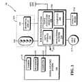
- Figure 1illustrates a rail vision system capable of functioning as an automatic train protection system. It is intended for use on trains designed for travel along a railway track featuring a multiplicity of wayside signal devices. It is well known that each wayside signal device communicates from a railway operating authority signal aspect information as to how the train should proceed along the upcoming segment of railway track. This rail vision system can visually read the signal aspect information as the train approaches each wayside signal device and operate the brakes in compliance with the wayside signaling system.
- the rail vision system 10in its most basic form comprises a signal locating system 100 and a rail navigation system 200.
- the signal locating system 100features an input means 110, a processing means 120 and, optionally, a computing device 130 depending on how the overall system 10 is configured.
- the input means 110can take the form of any one of a variety of known cameras including the types of cameras that feature aiming and zooming mechanisms that can be externally controlled to aim the camera at an upcoming object with high clarity even at relatively long distances. It is to be used to generate a video signal indicative of an image of the object, such as an upcoming wayside signal device, onto which it is focused.
- the processing means 120may take the form of any one of several types of hardware and software embodiments known in the signal processing art.
- the processing means 120is to be used to process the video signal generated by the camera 110 so that the upcoming wayside signal device, and the signal aspect information if appearing thereon, is rendered discernable.
- the particular technique and hardware/software embodiment one selects to implement the processing means 120will, of course, depend primarily on cost.
- the signal locating system 100is used to isolate visually the upcoming wayside signal device and to read the information therefrom as the train approaches it.
- the rail navigation system 200is used to determine the position that the train occupies on the railway track. It is also used to provide the signal locating system 100 with data as to the whereabouts of the upcoming wayside signal device relative to the position of the train. This enables the signal locating system 100 to isolate visually the upcoming wayside signal device and to provide the information read therefrom to the rail navigation system 200.
- the rail vision system 10is used to detect and react to obstructions on the railway track. Illustrated also in Figure 2, this embodiment is designed for trains that travel along railway routes that intersect with highways or other types of railway track crossings.
- the rail vision system 10includes the signal locating system 100 and the rail navigation system 200 as indicated before.
- the database stored in storage device 210will include preferably the location of every highway or other type of crossing on each railway route.
- the databasewill also preferably include data pertaining to the distance from each crossing at which imaging should start.
- the computer 240uses the enumerated signals along with and in comparison to the aforementioned data to determine the position that the train occupies on the railway route. Most important, the computer 240 will also calculate the whereabouts of the upcoming crossing relative to the position of the train. Apprised of the expected location of the crossing by computer 240, the computing device 130 of the signal locating system 100 directs the camera 110 to focus on the upcoming crossing. The processing means 120 attempts to render the upcoming crossing discernable by processing the video signal generated by camera 110 according to known signal processing techniques. As the train approaches closer to the crossing, the computing device 130 conveys to computer 240 increasingly accurate information as to whether there is an obstruction on the crossing and, if so, whether that obstruction is stationary or moving.
- the computing device 130can preferably also provide a confidence factor based on the quality of the sighting.
- the sighting of the crossingmay also be used to corroborate the calculations of the computer 240 as to, for example, the track on which the train is traveling and the position that the train occupies on that track.
- the upcoming crossing and whatever obstruction may be blocking itcan be displayed on the display unit 225 along with any other intelligence gathered or calculated by the system 10.
- the rail vision system 10will preferably warn the train operator of the obstruction via an audible or visual warning. Though the train may not be able to stop within the viewing distance to the upcoming crossing, the rail vision system 10 will provide the train operator with a warning in advance of the time at which the obstruction would otherwise be viewable by the train operator. The train operator will thus be alerted to apply the brakes far earlier than would otherwise be possible and thereby lower the speed at which the train will encounter the crossing.
- the computer 240could also be used to brake the train. For example, if the train operator does not initiate a brake application within a given time, the computer 240 could be used to deenergize automatically the power feed circuit 214 thereby imposing a penalty brake application to stop the train.
- This embodiment of the rail vision system 10also features a video recorder 170.
- the computer 240is used to activate the video recorder 170 when an obstruction is detected on the upcoming crossing.
- the video recorder 170could take the form of a magnetic tape recorder.
- a computer hard drivemay be used to store in digital format the visual record of any such event. Such a video record would ideally be used to assist accident investigators in ascertaining the cause of collisions at highway crossings.
- the rail navigation system 200includes preferably a storage device 210, a speed sensing device 213, a rate of turn measuring apparatus 220, a navigational receiver 230 and a computer 240.
- the storage device 210is primarily used to store a database composed of a variety of information. As recited in the aforementioned U.S. Patent 5,740,547 A, the database includes data pertaining to (i) the locations of railway track routes and (ii) the locations and orientations of curves and switches in those railway track routes.
- the databasealso features data pertaining to (iii) the location of each wayside signal device on each railway track route, (iv) the type of each wayside signal device (e.g., background shape, number of lights, possible color combinations), (v) the direction which each wayside signal device points (e.g., eastbound or westbound, etc.) and the particular track which each wayside signal device signals (e.g., main track or siding), (vi) the position of each wayside signal device with respect to the particular track and the direction which the train is travelling (e.g., to the right, left, overhead), (vii) the distance from each wayside signal device at which imaging of the object should start, (viii) the signal number that appears on the signboard of each wayside signal device so equipped, and (ix) the position of the signboard for each wayside signal device so equipped.
- the type of each wayside signal devicee.g., background shape, number of lights, possible color combinations
- the direction which each wayside signal device pointse.g., eastbound or westbound,
- the databasemay also feature data pertaining to (x) the location of every highway or other type of crossing on all relevant railway track routes and (xi) the distance from each crossing at which imaging should start. This location data is pegged to the identity of each railway route typically by reference to milepost distances.
- the speed sensing device 213can take the form of an axle generator, a traction motor speed sensor or other type of known device. It is used to sense the rotation of one of the axles of the locomotive through which it generates a first signal from which the speed of the train can be determined. Speed sensing device 213 can take the form of an odometer to determine the distance that the train has traveled over time. The signal from the odometer could be differentiated in time to ascertain the speed of the train.
- the rate of turn measuring apparatus 220 and the navigational receiver 230are described in the aforementioned U.S. Patent 5,740,547 A.
- the rate of turn measuring apparatus 220measures the rate at which the train turns while traveling on curves in the railway track. It may take the form of a gyroscope through which to generate a second signal from which curvature of the railway track can be determined.
- the navigational receiver 230is used to determine the position that the train occupies on the globe. It is preferred that the navigational receiver 230 take the form of a GPS receiver which can receive global coordinates, such as latitude and longitude, from earth orbiting satellites. The GPS receiver may also be used to provide heading information. The GPS receiver should be accurate enough to identify a curve or a switch on which the train is located.
- the GPS receiver itselfmay provide may only be an approximation of the exact location that the train occupies on the globe. It is this navigational receiver 230 that generates a third signal indicative of the approximate position of the train about the railway track.
- the computer 240uses the enumerated signals along with and in comparison to the aforementioned data to determine not only the position that the train occupies on the railway track but also the whereabouts of the upcoming wayside signal device relative to the position of the train. Specifically, the computer 240 determines where the train is located in relation to the track route location data stored in the on-board database. Through such processing, the coordinates the train occupies on the globe are matched against the database information to determine not only on which track the train is traveling but also the particular segment and position that the train occupies on that track.
- the computer 240updates the expected location and position of the upcoming wayside signal device, relative to the position of the train, as the train continues its approach to it. It is expected that frequent updating will improve the ability of the system to locate the upcoming wayside signal device especially when the train approaches it along a curved track from which the viewing angle may vary significantly.
- the computing device 130 of the signal locating system 100directs the camera 110 to focus on the upcoming wayside signal device. Processing the video signal generated by the camera 110, the processing means 120 attempts to render the upcoming wayside signal device, and the signal aspect information appearing thereon, discernable.
- the computing device 130conveys to the computer 240 the signal aspect as read and a confidence factor based on the quality of the sighting.
- the identification of each wayside signal devicecan also be used to corroborate the calculations of the computer 240 as to, for example, the track on which the train is traveling and the position that the train occupies on that track.
- the signal locating system 100in its initial sighting, is unlikely to read the signal number that appears on the signboard of the upcoming wayside signal device.
- the signal aspect informationcould change as the train approaches the upcoming wayside signal device.
- the signal locating system 100will continue to track the wayside signal device and report any change in signal aspect as it occurs.
- the signal locating system 100will pass that information to the computer 240.
- the computer 240determines that the train shall soon pass the upcoming wayside signal device, it will inform the signal locating system.100 accordingly.
- the computer 240will use the last reported signal aspect information to operate the brakes of the train in compliance with signal aspect information received from the upcoming wayside signal device.
- the functions attributed to the computing device 130 of the signal locating system 100 and the those attributed to the computer 240 of the rail navigation system 200could essentially be performed by one computer. Accordingly, the computer 240 could perform some or even more of the functions ascribed to the computing device 130 or to the other components of the signal locating system 100.
- the computer 240can operate the brakes of the train in compliance with the wayside signaling system whether the particular track segment that the train is encountering is covered by a wayside signal device and whether the signal aspect information is actually received as the train approaches that particular segment of track. Apprised of the position of the train, the computer 240 determines whether and how the brakes of the train will be operated should the train operator be required and fail to operate the brakes according to one or more braking profiles calculated by the computer.
- the computer 240continuously updates the braking profiles based on a variety of parameters including the aforementioned data, the enumerated signals, and the signal aspect information obtained from the last wayside signal device.
- the process through which the braking profiles are calculatedis, of course, well known in the train braking art. Typically two sets of braking profiles will be computed, one for full service braking and the other for emergency braking. Each braking profile will be calculated as a speed distance curve from a target stopping point.
- the braking profileswill be used to enforce the wayside signaling system in a manner least disruptive to train handling and normal operations.
- the last signal aspect information receivedwill be used to determine the extent of the current operating authority for the train.
- the computer 240continuously calculates two speed-distance braking profiles.
- the service braking profileis derived so that a full service brake application would be able to stop or slow the train over the distance between the current position of the train and the desired stopping point.
- the emergency braking profileis derived so that an emergency brake application would be able to stop the train in the distance between the current position of the train and the desired point.
- the rail vision system 10will brake the train accordingly.
- the rail vision system 10operates the brakes in compliance with the wayside signaling system without the need for AC track circuits, transponders or radio to communicate the signal aspect information.
- the rail vision 10may also include an acknowledgment input 260 whose output is provided to the computer 240.
- the acknowledgment input 260could preferably be used to silence the audible and visual warning devices that would be generated following a failure to respond to the more restrictive signal aspects.
- the automatic train protection function of this embodimentlargely obviates conventional uses of the acknowledgment input (i.e., preventing a penalty brake application).
- the rail vision system 10may also feature a display unit 225 to show the train operator a wide variety of intelligence gathered or calculated by the invention.
- the display unit 225may feature the aspect display 150 traditionally used in trains equipped with cab signal devices.
- the rail vision system 10may operate the aspect display 150 in any one of two ways. It may illuminate the aspect indicators only when signal aspect information is actually received from the upcoming wayside signal device. Consequently, the aspect indicators would not be illuminated as the train passes through those track segments that are not covered by wayside signal devices.
- the rail vision system 10may operate the aspect display so that it always displays some indication whether or not the train is travelling on a track segment covered by a wayside signal device.
- the aspect indicatorscould be illuminated to indicate the prevailing signal aspect as the train passes through those track segments that are covered by wayside signal devices.
- the aspect display 150could be illuminated to indicate a signal aspect that is one level more restrictive than that received from the last wayside signal device passed.
- the rail vision system 10could be used to operate the brakes as if it actually received such unsignaled signal aspects.
- the display unit 225may also feature a graphical display 250. This graphical display could be used to provide the train operator with the actual video image generated by the camera 10. It may also be used to display supplemental information such as the profile of the upcoming portion of railway track, the estimated distance required to brake the train, the territorial coverage of the railway operating authority or other data.
- the first signal output from the speed sensing device 213may, of course, take the form of pulses at a frequency proportional to the rate at which the axle rotates.
- the rail vision system 10could be used to shutdown automatically the engine of the locomotive should the speed of the train exceed a predetermined value.
- the computer 240 of the rail navigation system 200preferably merely warns the train operator of the more restrictive signal aspects. Moreover, if the train operator fails to acknowledge the warning, the rail navigation system 200 imposes a penalty brake application.
- the rail vision 10therefore includes preferably an acknowledgment input 260 and a means for imposing a penalty brake application 214.
- the acknowledgment input 260provides its output to the computer 240 of the rail navigation system 200. It can be used to silence the audible warning devices that would be generated following a failure to respond to the more restrictive signal aspects.
- the means for imposing the penalty brake application 214can take the form of any one of a wide variety of known arrangements. For example, a power feed circuit can be used to energize, and thus keep closed, an electropneumatic valve that if opened would vent the brake pipe to atmosphere and apply the brakes.
- the power feed circuitmay also be used as an input to a modern brake control system through which to provide the same function.
- the computer 240will brake the train. For example, should the speed of the train approach too close to the service brake curve, the train operator would be warned via an audible warning device. If the train operator does not initiate a brake application so that the train comports with the service braking profile, the computer 240 will automatically deenergize the power feed circuit to impose a penalty brake application to stop the train. Similarly, if the speed of the train should approach too close to the emergency brake curve, the train operator would again be warned. If the train operator does not apply the brakes so that the train comports with the emergency braking profile, the computer 240 will automatically impose a penalty brake application to stop the train. For the service braking profile, the penalty brake application would normally be imposed at a full service rate. For the emergency braking profile, it could be imposed at an emergency rate.
- the rail vision system 10can be configured to respond in any number of ways to signal aspect information.
- the first embodimentfor example, primarily is used to operate the brakes in compliance with the wayside signaling system in a manner similar to that of an automatic train protection system.
- the second embodimentis used primarily to detect the more restrictive signal aspects and impose a penalty brake application if the train operator fails to acknowledge them.
- the inventioncan be used with existing signaling systems without the need to modify such infrastructure.
- the display unit 225may be used to show the signal aspects received from the upcoming wayside signal device as well as other intelligence gathered or calculated by the system 10. This includes the actual video image generated by the camera 10 and supplemental information such as the profile of the upcoming portion of railway track and the territorial coverage of the railway operating authority as well as other data.
Landscapes
- Engineering & Computer Science (AREA)
- Mechanical Engineering (AREA)
- Physics & Mathematics (AREA)
- Electromagnetism (AREA)
- Health & Medical Sciences (AREA)
- General Health & Medical Sciences (AREA)
- Toxicology (AREA)
- Train Traffic Observation, Control, And Security (AREA)
Description
- This application is related to U.S. Patent 5,995,881 A,titled "INTEGRATED CAB SIGNAL AND RAIL NAVIGATION SYSTEM",which was issued on November 30, 1999 and granted based on U.S. applicationserial number 08/898373. This patent is also assignedto the assignee of the present invention.
- The present invention generally relates to a system used toenforce braking of a train in compliance with the signal aspectinformation received from the wayside signal devices of a waysidesignaling system. More particularly, the present invention relates toa rail vision system that can visually read the signal aspectinformation as the train approaches each wayside signal device andoperate the brakes in compliance therewith. Still more particularly,the rail vision system can be used merely to warn a train operator ofonly the more restrictive signal aspects received from a wayside signaldevice and, should the train operator fail to acknowledge the warning,impose a penalty brake application.Such a rail vision system is disclosed in German Patent DE 195 38 022 C1.
- A railway operating authority is responsible for conducting railtraffic safely along the railway track routes under its control. Themovement of one or more trains along a railway track route can begoverned in a variety of ways. For multiple trains travelling on anunsignaled route (i.e., in dark territory), the operating authority typically issues orders by radio to the operator of each train so as tomaintain adequate separation between trains and otherwise safely guideeach train through such territory. For trains travelling on a routeequipped with a wayside signaling system, the operating authority guideseach train via wayside signal devices dispersed at various intervalsthroughout the length of the railway route. Though trains can be guidedsafely along unsignaled routes, wayside signaling systems arepreferable, especially on heavily trafficked routes, as they can be usedto guide trains even more safely and more quickly along such signaledroutes with less distance between them.
- It is well known that a wayside signaling system is used tocommunicate signal aspect information to a train as it travels along therailway route. One type of wayside signaling system features acontinuous succession of DC train detection circuits along the entirelength of the railway route through which to control a multiplicity ofwayside signal devices spaced apart from each other along the route.Each train detection circuit covers a section of track approximately10,000 feet in length and is electrically isolated from the nextdetection circuit via an insulated joint situated between each tracksection. Each train detection circuit merely detects whether itssection of track is occupied by a train and communicates a signalindicative of same to its corresponding wayside signal device. For thistype of wayside signaling system, each wayside signal device typicallytakes the form of a display of colored lights or other indicia throughwhich to visually communicate signal aspect information to a train operator. It is the signal aspect information that denotes thecondition of the upcoming segment of track, i.e., whether it is clear,occupied by a train or subject to some other speed restriction.
- Each signal aspect is conveyed by a color or combination ofcolors and denotes a particular course of action required by theoperating authority. The particular colors of red, yellow and greengenerally denote the same meaning as when used on a standard trafficlight. In a four aspect wayside signaling system, for example, thefollowing scheme may be employed: green for clear, yellow and green forapproach medium, yellow for approach, and red for restricted/stop. Ifa train is detected on a section of track, the train detection circuitcorresponding thereto informs its corresponding wayside signal device.As the train approaches a track segment over which the wayside signaldevice has coverage, the railway authority that operates that segmentthen uses the wayside signal device to communicate visually theappropriate signal aspect to the train operator.
- Another type of wayside signaling system also features thecontinuous succession of DC train detection circuits along the railwaytrack route. They, too, are used to control the wayside signal devicesspaced along the route. Each of the wayside signal devices in this typeof signaling system also includes an AC track circuit that accompaniesor overlays each DC train detection circuit and serves to supplement itsvisual display. Each wayside signal device through its AC track circuitcommunicates over the rails the signal aspect information (i.e., the cabsignal) up to a range of approximately 5,000 feet. As a train rides on the rails, the cab signal is sensed by pick up coils mounted in frontof the leading axle of the locomotive. The cab signal is filtered,decoded and eventually conveyed to a cab signal device located in thecab of the locomotive. The cab signal device typically includes adisplay of colored lights to convey visually the signal aspectinformation so that the train operator will be kept apprised of thesignal aspect applicable to the upcoming segment of track.
- Most railway operating authorities such as Conrail and UnionPacific, for example, use the four aspect system to communicate thecondition of the upcoming track segment. Each of the wayside signaldevices in such a system typically takes the form of an AC powerfrequency track circuit from which a carrier frequency typically rangingbetween 50 to 100 Hertz carries the cab signal in coded format. In thisfour aspect wayside signaling system, each signal aspect is communicatedvia electrical pulses in the aforementioned way to the cab signal deviceusing the following preset code rates: 180 pulses per minute for Clear,120 for Approach Medium, 75 for Approach, and 0 for Restricted/Stop.Each of the latter three aspects imposes a restriction in the speed withwhich the train may proceed along that segment of railway track.
- Two trains travelling in the same direction along a railway routeequipped with a three aspect wayside signaling system may be directed,for example, as follows. One train approaches a wayside signal devicethat is displaying a green/clear aspect indicating that it is clear toproceed on the upcoming segment of track. Meanwhile another trainsituated two segments ahead is stopped on a track segment whose wayside signal device is displaying a red/stop aspect. The next signal that thetrailing train encounters is a yellow/approach aspect because theleading train is occupying the track segment governed by the waysidesignal device that is displaying the red/stop aspect. Theyellow/approach aspect typically indicates that the trailing train mustreduce its speed and be prepared to stop before encountering the tracksegment covered by the next wayside signal device. If the leading trainstill has not moved, the trailing train must stop before it reaches thenext wayside signal device because that signal device is the one thatis still displaying the red/stop aspect.
- Railway equipment manufacturers have offered a variety of systemswhose objective is to operate the brakes of a train in compliance withsuch directions issued by the railway operating authorities. Thesesystems typically employ the cab signal devices in conjunction withautomatic train protection (ATP) systems. By processing the directionsreceived from the wayside signaling systems according to knownprinciples, such prior art devices and systems are used to derive, andrequire the train to comport with, braking profiles. These prior artsystems typically brake the train automatically when the train operatescontrary to the limits imposed by the braking profiles and thus contraryto the wayside signaling system on which the train is riding.
- The cab signal device thus typically features an audible warningdevice and an acknowledgment input. The acknowledgment input allows thetrain operator to acknowledge the more restrictive signal aspects andthereby prevent a penalty brake application. For example, when the train encounters a segment of track over which one of the speedrestrictions is in force and the train is nevertheless permitted toexceed the speed restriction, the cab signal device will activate theaudible warning device. If the train operator does not initiate aservice brake application so that the train comports with the calculatedspeed distance braking profile, the cab signal device will automaticallyimpose a penalty brake application to stop the train. The cab signaldevice typically provides power continuously to a feed circuit toenergize, and thus keep closed, an electropneumatic valve. Should thetrain run afoul of the speed distance braking profile, the cab signaldevice denergizes the valve to vent the brake pipe to atmosphere therebyapplying the brakes. In newer locomotives equipped with modern brakecontrol systems such as the WABCO EPIC® system, the cab signal deviceoffers a similar input to the electronic brake control system to providethe same function.
- Some cab signal devices also offer overspeed protection as anoptional feature. A speed sensing device provides an indication ofspeed to the cab signal device. The cab signal device automaticallyshuts down the engine of the locomotive if the speed of the trainexceeds a predetermined value.
- The territorial coverage of the DC train detection circuits andthe wayside signal device AC track circuits is typically notcoextensive. Whereas each DC train detection circuit covers a sectionof track approximately 10,000 feet in length, each wayside signal devicethrough its AC track circuit can typically apply its cab signal on a reliable basis to a range of about 5,000 feet. Consequently, repeaterunits are often used to fill the gaps so as to provide continuous cabsignal coverage between wayside signal devices.
- The cab signal devices on present day trains are designed tooperate on wayside signaling systems that provide continuous coverageover the entire track route. Should a wayside signal device or arepeater unit fail, the cab signal device will interpret the loss ofsignal aspect information as a stop aspect and automatically impose apenalty brake application. Though the train operator can typicallyprevent a penalty brake application by acknowledgment or other actions,it is generally not operationally acceptable to routinely requirerepeated wayside signal "cut-out" and "cut-in" procedures to cover suchloss of coverage. Though such wayside signaling systems are widely usedon both freight railroads and passenger transit properties, they havenot been extensively deployed on the longer freight railroad routes.This is primarily due to cost considerations . It is quite expensiveto equip railway track routes with wayside signal devices let alone thenecessary repeater units. The need for repeater units alone can oftenmore than double the cost of implementing a wayside signaling system.This increase in cost is due to the need for infrastructure such asacquiring sites at which to install the equipment and providing thefoundations, equipment housings and power access at those sites. Manyrailway routes therefore have the type of wayside signaling system inwhich there are gaps in cab signal coverage because repeater unitseither are not used or only used in certain places.
- For heavy freight trains with conventional continuous cab signaldevices, it is generally not practical to provide automatic train stoptechniques to enforce braking. Several factors such as the brakingcharacteristics, the signal block lengths and grades for any given trainand terrain are not known and thus worst case conditions would thereforehave to be assumed. This would result in overly restrictive brakingcurve assumptions for most cases, which would affect train operationstoo severely to be practical. Consequently, most freight trainoperators with continuous cab signal devices (e.g., Conrail and UnionPacific Railroads), provide only a warning of the more restrictivesignal aspects, with an acknowledgment requirement. The penalty brakesare applied automatically only if the train operator fails toacknowledge the more restrictive signal aspects. The train operator canthus satisfy the acknowledgment requirement, yet still not apply thebrakes so as to stop the train before approaching a red signal.
- Yet another type of wayside signaling system also features thecontinuous succession of DC train detection circuits along the railwaytrack route. They, too, are used to control the wayside signal devicesspaced along the route. In this type of wayside signaling system,however, each of the wayside signal devices controls a track transponderlocated at a fixed point along the track before each wayside signaldevice. When a train is detected on a section of track, the traindetection circuit corresponding thereto informs its correspondingwayside signal device. The train, however, can only receive the signalaspect information from the transponder as it passes by each fixed point. By using the track transponders to transmit additional encodeddata such as the profile of the upcoming track segment and the signalblock length, a train equipped with an automatic train protection (ATP)system is able to enforce braking on routes covered by such a waysidesignaling system.
- The primary disadvantage of transponder based ATP systems is thattrains so equipped are required to pass discrete points on the railwaytrack to receive the updated signal aspect information. Some railwayauthorities have therefore used radio systems to supplement theinformation received from the track transponders. Other authoritieshave used fixed transponders only, with updated information transmittedby radio from the wayside signal devices.
- Another shortcoming common to all transponder based ATP systemsis that they are rather expensive to install and maintain. Maintenance,for example, typically requires replacement of transponders that aredamaged. Maintenance may also require a change in the codes or thelocations of the transponders as the configuration of the railway trackmay well be changed over time.
- Current automatic train protection systems present significantdisadvantages whether used in connection with wayside signaling systemsfeaturing wayside signal devices having AC track circuits or fixed pointtransponders. For wayside signaling systems featuring wayside signaldevices featuring AC track circuits, it is expensive to equip railwayroutes with repeater units to prevent gaps in coverage from which signalaspect information would be unavailable. Moreover, the cab signal device will interpret such loss of the cab signal as a stop aspect andautomatically impose a penalty brake application. For wayside signalingsystems featuring wayside signal devices featuring fixed pointtransponders, a train equipped for travel on such routes is required topass fixed points to receive the updated signal aspect and guidanceinformation from the transponders. Transponder systems are alsoexpensive to install and maintain.
- There is therefore a need in the railroad industry for a systemthat could operate the brakes of a train in compliance with a waysidesignaling system without the aforementioned disadvantages.Specifically, it would be quite desirable to develop a system that canvisually read the signal aspect information from each wayside signaldevice of a wayside signaling system. Such a system could be designedto operate on any type of wayside signaling system that visuallydisplays the signal aspect information.
- Related to the invention is subject matter described and claimedin U.S. Patent 5,740,547 A entitled Rail Navigation System,which was issued on April 14, 1998 and granted based on U.S. application serialnumber 08/604,032, filed February 20, 1996. This patentis assigned to the assignee of the present invention.The railnavigation system allows a train to locate the position it occupies ona railway track route.
- As best described in the cited document, the rail navigationsystem features a database including data pertaining to the locationsof railway track routes and the locations and orientations of curves and switches in those railway track routes. It also receives inputs fromdevices such as an odometer, a rate of turn measuring apparatus and anavigational receiver. According to instructions contained within itsprogramming code, the rail navigation system uses the aforementioneddata along with and in comparison to the enumerated inputs to determinewhere the train is located in relation to track route location datastored in the on-board database. Through such processing, thecoordinates the train occupies on the globe are matched against thedatabase information to determine not only on which track the train istraveling but also the particular position that the train occupies onthat track.
- It should be noted that the foregoing background information isprovided to assist the reader in understanding the instant invention.Accordingly, any terms used herein are not intended to be limited to anyparticular narrow interpretation unless specifically stated otherwisein this document.
- It is, therefore, a primary objective of the invention to visually determine when an upcomingcrossing is obstructed and automatically make a visual record of theencounter between the train and the crossing.
- Yet another objective is to provide a rail vision system that canvisually determine whether an upcoming crossing is obstructed andautomatically warn the train operator accordingly.
- Even another objective is to integrate video signal processingtechniques into a rail navigation system so that the task of visuallyreading and acting upon signal aspect information from the waysidesignal devices of a wayside signaling system is both technicallypractical and economically feasible.
- A further objective is to develop a rail vision system that canbe used with a wayside signaling system whose coverage does not extendthroughout the entire railway route.
- Yet a further objective is to develop a rail vision system thatcan operate the brakes of a train in compliance with a wayside signalingsystem without the need to retrofit or otherwise modify the existinginfrastructure of the wayside signaling system.
- Still a further objective is to develop a rail vision systemcapable of acting as an automatic train protection system and one thatcan be implemented on nearly all types of trains with minimum affect oncurrent train handling practices and operations.
- Even a further objective is to implement a rail vision systemcapable of performing generally the same functions as, and at lower costthan, alternative radio based "Positive Train Separation" and "AdvancedTrain Control" systems currently being considered or developed by othermanufacturers.
- Yet a further objective is to develop a rail vision system thatcan be incrementally incorporated into more and more trains on anindividual basis without requiring that every train operating in thesame area be equipped before any one train can derive the advantages ofusing the present invention.
- In addition to the objectives and advantages listed above,various other objectives and advantages of the invention will becomemore readily apparent to persons skilled in the relevant art from areading of the detailed description section of this document. The otherobjectives and advantages will become particularly apparent when thedetailed description is considered along with the attached drawings andwith the appended claims.
- The invention providesa rail vision system for a train that is designed for travel along arailway track featuring a multiplicity of wayside signal devices. Eachwayside signal device communicates from a railway operating authorityinformation as to how the train should proceed along the upcomingsegment of railway track. The rail vision system includes a signallocating system and a rail navigation system. As the train approaches each wayside signal device, the signal locating system isolates visuallythe upcoming wayside signal device and reads the information whenavailable therefrom. The rail navigation system determines the positionthat the train occupies on the railway track and provides the signallocating system with data as to the whereabouts of the upcoming waysidesignal device relative to the position of the train. This enables thesignal locating system to isolate visually the upcoming wayside signaldevice when the train approaches thereto. When the information isavailable, the signal locating system reads it and then provides it tothe rail navigation system. The rail navigation system operates thebrakes of the train in compliance with the wayside signaling systemwhether the particular track segment that the train is encountering iscovered by a wayside signal device and whether the information isactually received as the train approaches that particular segment oftrack.
- The invention providesa rail vision system for a train that is designed for travel along arailway track having a multiplicity of highway or any other crossingsintersecting therewith.The signal locatingsystem isolates visually the upcoming crossing as the train approachesthereto. The rail navigation system determines the position that thetrain occupies on the railway track and provides the signal locatingsystem with the whereabouts of the upcoming crossing relative to theposition of the train. This enables the signal locating system toisolate visually the upcoming crossing and to inform the rail navigationsystem as to the condition of the upcoming crossing.A visual record of the encounter between the train and the crossing is made whenactivated by the rail navigation system in case of the upcoming crossing being obstructed. As the trainapproaches the upcoming crossing, the rail navigation system can thenwarn the train operator when the upcoming crossing is obstructed.
- In a preferred embodiment, the inventionprovides a rail vision system for a train that is designed for travelalong a railway track featuring a multiplicity of wayside signaldevices. Each wayside signal device communicates from a railwayoperating authority information including directions as to how the trainshould proceed along the upcoming segment of railway track. The railvision system includes a signal locating system and a rail navigationsystem. The signal locating system isolates visually the upcomingwayside signal device and reads the information therefrom as the trainapproaches thereto. The rail navigation system determines the position that the train occupies on the railway track and provides the signallocating system with data as to the whereabouts of the upcoming waysidesignal device relative to the position of the train. This enables thesignal locating system to isolate visually the upcoming wayside signaldevice and to provide the information read therefrom to the railnavigation system. The rail navigation system can then warn a trainoperator of the more restrictive of the directions, and should the trainoperator fail to acknowledge the warning, impose a penalty brakeapplication.
- Figure 1 illustrates in block forma rail vision system for a train.
- Figure 2 illustrates in block form a presently preferredembodiment of a rail vision system for a train according to the invention.
- Before describing the invention in detail, the reader is advisedthat, for the sake of clarity and understanding, identical componentshaving identical functions in each of the accompanying drawings havebeen marked where possible with the same reference numerals in each ofthe Figures provided in this document.
- Figure 1 illustratesa rail vision system capable of functioningas an automatic train protection system. It is intended for use ontrains designed for travel along a railway track featuring amultiplicity of wayside signal devices. It is well known that eachwayside signal device communicates from a railway operating authoritysignal aspect information as to how the train should proceed along theupcoming segment of railway track. This rail vision system can visuallyread the signal aspect information as the train approaches each waysidesignal device and operate the brakes in compliance with the waysidesignaling system.
- The
rail vision system 10 in its most basic form comprises asignal locating system 100 and arail navigation system 200. Thesignallocating system 100 features an input means 110, a processing means 120 and, optionally, acomputing device 130 depending on how theoverallsystem 10 is configured. The input means 110 can take the form of anyone of a variety of known cameras including the types of cameras thatfeature aiming and zooming mechanisms that can be externally controlledto aim the camera at an upcoming object with high clarity even atrelatively long distances. It is to be used to generate a video signalindicative of an image of the object, such as an upcoming wayside signaldevice, onto which it is focused. The processing means 120 may take theform of any one of several types of hardware and software embodimentsknown in the signal processing art. Using any number of wellestablished signal processing techniques, the processing means 120 isto be used to process the video signal generated by thecamera 110 sothat the upcoming wayside signal device, and the signal aspectinformation if appearing thereon, is rendered discernable. Theparticular technique and hardware/software embodiment one selects toimplement the processing means 120 will, of course, depend primarily oncost. - The
signallocating system 100 is used to isolate visually the upcoming waysidesignal device and to read the information therefrom as the trainapproaches it. Therail navigation system 200 is used to determine theposition that the train occupies on the railway track. It is also usedto provide thesignal locating system 100 with data as to thewhereabouts of the upcoming wayside signal device relative to theposition of the train. This enables thesignal locating system 100 toisolate visually the upcoming wayside signal device and to provide theinformation read therefrom to therail navigation system 200. - Referring now to a presently preferred embodiment of theinvention, the
rail vision system 10 is used to detect andreact to obstructions on the railway track. Illustrated also in Figure2, this embodiment is designed for trains that travel alongrailway routes that intersect with highways or other types of railwaytrack crossings. - The
rail vision system 10 includes thesignal locating system 100 and therail navigation system 200 as indicated before.The database stored instorage device 210,however, will include preferably the location of every highway or other type ofcrossing on each railway route. The database will also preferablyinclude data pertaining to the distance from each crossing at whichimaging should start. - As described previously, the
computer 240 uses the enumeratedsignals along with and in comparison to the aforementioned data todetermine the position that the train occupies on the railway route.Most important, thecomputer 240 will alsocalculate the whereabouts of the upcoming crossing relative to theposition of the train. Apprised of the expected location of thecrossing bycomputer 240, thecomputing device 130 of thesignallocating system 100 directs thecamera 110 to focus on the upcomingcrossing. The processing means 120 attempts to render the upcomingcrossing discernable by processing the video signal generated bycamera 110 according to known signal processing techniques. As the trainapproaches closer to the crossing, thecomputing device 130 conveys tocomputer 240 increasingly accurate information as to whether there isan obstruction on the crossing and, if so, whether that obstruction isstationary or moving. Thecomputing device 130 can preferably also provide a confidence factor based on thequality of the sighting. The sighting of the crossing may also be usedto corroborate the calculations of thecomputer 240 as to, for example,the track on which the train is traveling and the position that thetrain occupies on that track. The upcoming crossing and whateverobstruction may be blocking it can be displayed on thedisplay unit 225along with any other intelligence gathered or calculated by thesystem 10. - Unless the upcoming crossing is clear or the obstruction soonmoves from it, the
rail vision system 10 will preferably warn the train operatorof the obstruction via an audible or visual warning. Though the trainmay not be able to stop within the viewing distance to the upcomingcrossing, therail vision system 10 will provide the train operator witha warning in advance of the time at which the obstruction wouldotherwise be viewable by the train operator. The train operator willthus be alerted to apply the brakes far earlier than would otherwise bepossible and thereby lower the speed at which the train will encounterthe crossing. - It should be apparent that should the train operator fail toacknowledge the warning, the
computer 240 could also be used to brake the train. For example, if the train operator does not initiate a brakeapplication within a given time, thecomputer 240 could be used todeenergize automatically thepower feed circuit 214 thereby imposing apenalty brake application to stop the train. - This embodiment of the
rail vision system 10 alsofeatures avideo recorder 170. Thecomputer 240 is used toactivate thevideo recorder 170 when an obstruction is detected on theupcoming crossing. Thevideo recorder 170 could take the form of amagnetic tape recorder. Alternatively, a computer hard drive may beused to store in digital format the visual record of any such event.Such a video record would ideally be used to assist accidentinvestigators in ascertaining the cause of collisions at highwaycrossings. - The
rail navigation system 200 includes preferably astorage device 210, aspeed sensing device 213, a rate ofturn measuring apparatus 220, anavigational receiver 230 and acomputer 240. Thestorage device 210is primarily used to store a database composed of a variety ofinformation. As recited in the aforementioned U.S.Patent 5,740,547 A, the database includes data pertaining to (i)the locations of railway track routes and (ii) the locations andorientations of curves and switches in those railway track routes. - The database also features datapertaining to (iii) the location of each wayside signal device on eachrailway track route, (iv) the type of each wayside signal device (e.g.,background shape, number of lights, possible color combinations), (v)the direction which each wayside signal device points (e.g., eastboundor westbound, etc.) and the particular track which each wayside signaldevice signals (e.g., main track or siding), (vi) the position of eachwayside signal device with respect to the particular track and thedirection which the train is travelling (e.g., to the right, left,overhead), (vii) the distance from each wayside signal device at whichimaging of the object should start, (viii) the signal number thatappears on the signboard of each wayside signal device so equipped, and(ix) the position of the signboard for each wayside signal device soequipped. As explained below, the database may also feature datapertaining to (x) the location of every highway or other type ofcrossing on all relevant railway track routes and (xi) the distance fromeach crossing at which imaging should start. This location data ispegged to the identity of each railway route typically by reference tomilepost distances.
- The
speed sensing device 213 can take the form of an axlegenerator, a traction motor speed sensor or other type of known device.It is used to sense the rotation of one of the axles of the locomotivethrough which it generates a first signal from which the speed of thetrain can be determined.Speed sensing device 213 can take the form ofan odometer to determine the distance that the train has traveled over time. The signal from the odometer could be differentiated in time toascertain the speed of the train. - The rate of
turn measuring apparatus 220 and thenavigationalreceiver 230 are described in the aforementioned U.S.Patent 5,740,547 A. The rate ofturn measuring apparatus 220measures the rate at which the train turns while traveling on curves inthe railway track. It may take the form of a gyroscope through whichto generate a second signal from which curvature of the railway trackcan be determined. Thenavigational receiver 230 is used to determinethe position that the train occupies on the globe. It is preferred thatthenavigational receiver 230 take the form of a GPS receiver which canreceive global coordinates, such as latitude and longitude, from earthorbiting satellites. The GPS receiver may also be used to provideheading information. The GPS receiver should be accurate enough toidentify a curve or a switch on which the train is located. It isanticipated, however, that it will not be accurate enough to determineon which set of adjacent, parallel tracks the train may be located.Thus the data that the GPS receiver itself may provide may only be anapproximation of the exact location that the train occupies on theglobe. It is thisnavigational receiver 230 that generates a thirdsignal indicative of the approximate position of the train about therailway track. - According to instructions contained within its programming code,the
computer 240 uses the enumerated signals along with and incomparison to the aforementioned data to determine not only the position that the train occupies on the railway track but also the whereaboutsof the upcoming wayside signal device relative to the position of thetrain. Specifically, thecomputer 240 determines where the train islocated in relation to the track route location data stored in the on-boarddatabase. Through such processing, the coordinates the trainoccupies on the globe are matched against the database information todetermine not only on which track the train is traveling but also theparticular segment and position that the train occupies on that track. - Whether continuously or at predetermined intervals, the
computer 240 updates the expected location and position of the upcoming waysidesignal device, relative to the position of the train, as the traincontinues its approach to it. It is expected that frequent updatingwill improve the ability of the system to locate the upcoming waysidesignal device especially when the train approaches it along a curvedtrack from which the viewing angle may vary significantly. Apprised ofthe expected location and position by thecomputer 240, thecomputingdevice 130 of thesignal locating system 100 directs thecamera 110 tofocus on the upcoming wayside signal device. Processing the videosignal generated by thecamera 110, the processing means 120 attemptsto render the upcoming wayside signal device, and the signal aspectinformation appearing thereon, discernable. This involves identifyingthe portion of the video image in which to look for the wayside signaldevice and the signal aspect information it conveys. Thecomputingdevice 130 conveys to thecomputer 240 the signal aspect as read and aconfidence factor based on the quality of the sighting. The identification of each wayside signal device can also be used tocorroborate the calculations of thecomputer 240 as to, for example, thetrack on which the train is traveling and the position that the trainoccupies on that track. - The
signal locating system 100, in its initial sighting, isunlikely to read the signal number that appears on the signboard of theupcoming wayside signal device. The signal aspect information,moreover, could change as the train approaches the upcoming waysidesignal device. Apprised of the location and position of the upcomingwayside signal device bycomputer 240, thesignal locating system 100will continue to track the wayside signal device and report any changein signal aspect as it occurs. When the signal number on the signboardcan be read (where applicable), thesignal locating system 100 will passthat information to thecomputer 240. When thecomputer 240 determinesthat the train shall soon pass the upcoming wayside signal device, itwill inform the signal locating system.100 accordingly. Thecomputer 240 will use the last reported signal aspect information to operate thebrakes of the train in compliance with signal aspect informationreceived from the upcoming wayside signal device. - It should be apparent that the functions attributed to the
computing device 130 of thesignal locating system 100 and the thoseattributed to thecomputer 240 of therail navigation system 200 couldessentially be performed by one computer. Accordingly, thecomputer 240could perform some or even more of the functions ascribed to thecomputing device 130 or to the other components of thesignal locatingsystem 100. - The
computer 240 can operate the brakes of the train in compliance with the waysidesignaling system whether the particular track segment that the train isencountering is covered by a wayside signal device and whether thesignal aspect information is actually received as the train approachesthat particular segment of track. Apprised of the position of thetrain, thecomputer 240 determines whether and how the brakes of thetrain will be operated should the train operator be required and failto operate the brakes according to one or more braking profilescalculated by the computer. - The
computer 240 continuously updates the braking profiles basedon a variety of parameters including the aforementioned data, theenumerated signals, and the signal aspect information obtained from thelast wayside signal device. The process through which the brakingprofiles are calculated is, of course, well known in the train brakingart. Typically two sets of braking profiles will be computed, one forfull service braking and the other for emergency braking. Each brakingprofile will be calculated as a speed distance curve from a targetstopping point. - The braking profiles will be used to enforce the waysidesignaling system in a manner least disruptive to train handling andnormal operations. The last signal aspect information received will beused to determine the extent of the current operating authority for the train. Using the current position of the train and the desired pointat which the train should be stopped or slowed to a given speed, the
computer 240 continuously calculates two speed-distance brakingprofiles. Using the desired rate for full service braking, the servicebraking profile is derived so that a full service brake applicationwould be able to stop or slow the train over the distance between thecurrent position of the train and the desired stopping point. Using thedesired rate for emergency braking, the emergency braking profile isderived so that an emergency brake application would be able to stop thetrain in the distance between the current position of the train and thedesired point. Should the train be operating in a manner that iscontrary to the signal aspect information and at least one of thebraking profiles, therail vision system 10will brake the train accordingly.Therail vision system 10 operates the brakes incompliance with the wayside signaling system without the need for ACtrack circuits, transponders or radio to communicate the signal aspectinformation. - The
rail vision 10 may also include anacknowledgment input 260whose output is provided to thecomputer 240. Theacknowledgment input 260 could preferably be used to silence the audible and visual warningdevices that would be generated following a failure to respond to themore restrictive signal aspects. The automatic train protectionfunction of this embodiment largely obviates conventional uses ofthe acknowledgment input (i.e., preventing a penalty brake application). - The
rail vision system 10 may also feature adisplay unit 225 toshow the train operator a wide variety of intelligence gathered orcalculated by the invention. Thedisplay unit 225 may feature theaspect display 150 traditionally used in trains equipped with cab signaldevices. Depending on which option is preferred, therail vision system 10 may operate theaspect display 150 in any one of two ways. It mayilluminate the aspect indicators only when signal aspect information isactually received from the upcoming wayside signal device.Consequently, the aspect indicators would not be illuminated as thetrain passes through those track segments that are not covered bywayside signal devices. Alternatively, therail vision system 10 mayoperate the aspect display so that it always displays some indicationwhether or not the train is travelling on a track segment covered by awayside signal device. Specifically, the aspect indicators could beilluminated to indicate the prevailing signal aspect as the train passesthrough those track segments that are covered by wayside signal devices.When passing through track segments not covered by a wayside signaldevice, however, theaspect display 150 could be illuminated to indicatea signal aspect that is one level more restrictive than that receivedfrom the last wayside signal device passed. Moreover, therail visionsystem 10 could be used to operate the brakes as if it actually receivedsuch unsignaled signal aspects. - The
display unit 225 may also feature agraphical display 250.This graphical display could be used to provide the train operator withthe actual video image generated by thecamera 10. It may also be used to display supplemental information such as the profile of the upcomingportion of railway track, the estimated distance required to brake thetrain, the territorial coverage of the railway operating authority orother data. - Another optional feature of the invention could be to incorporateoverspeed protection into the
rail vision system 10. The first signaloutput from thespeed sensing device 213 may, of course, take the formof pulses at a frequency proportional to the rate at which the axlerotates. Using the first signal from thespeed sensing device 213, therail vision system 10 could be used to shutdown automatically the engineof the locomotive should the speed of the train exceed a predeterminedvalue. Thecomputer 240 of therail navigationsystem 200 preferably merely warns the train operator of the more restrictivesignal aspects. Moreover, if the train operator fails to acknowledgethe warning, therail navigation system 200 imposes a penalty brakeapplication. - The
rail vision 10 therefore includes preferably anacknowledgment input 260and a means for imposing apenalty brake application 214. Theacknowledgment input 260 provides its output to thecomputer 240 of therail navigation system 200. It can be used to silence the audiblewarning devices that would be generated following a failure to respondto the more restrictive signal aspects. The means for imposing thepenalty brake application 214 can take the form of any one of a widevariety of known arrangements. For example, a power feed circuit canbe used to energize, and thus keep closed, an electropneumatic valvethat if opened would vent the brake pipe to atmosphere and apply thebrakes. The power feed circuit may also be used as an input to a modernbrake control system through which to provide the same function. - Should the train operator fail to acknowledge the warningproperly such as by braking the train, the
computer 240 will brake thetrain. For example, should the speed of the train approach too closeto the service brake curve, the train operator would be warned via anaudible warning device. If the train operator does not initiate a brakeapplication so that the train comports with the service braking profile,thecomputer 240 will automatically deenergize the power feed circuitto impose a penalty brake application to stop the train. Similarly, if the speed of the train should approach too close to the emergency brakecurve, the train operator would again be warned. If the train operatordoes not apply the brakes so that the train comports with the emergencybraking profile, thecomputer 240 will automatically impose a penaltybrake application to stop the train. For the service braking profile,the penalty brake application would normally be imposed at a fullservice rate. For the emergency braking profile, it could be imposedat an emergency rate. - It should be apparent that the
rail vision system 10 can beconfigured to respond in any number of ways to signal aspectinformation. The first embodiment, for example, primarily is used tooperate the brakes in compliance with the wayside signaling system ina manner similar to that of an automatic train protection system. Thesecond embodiment is used primarily to detect the more restrictivesignal aspects and impose a penalty brake application if the trainoperator fails to acknowledge them. In either embodiment, the inventioncan be used with existing signaling systems without the need to modifysuch infrastructure. - The
display unit 225, of course, may be used to show the signalaspects received from the upcoming wayside signal device as well asother intelligence gathered or calculated by thesystem 10.
This includes the actual video image generated by thecamera 10 andsupplemental information such as the profile of the upcoming portion ofrailway track and the territorial coverage of the railway operatingauthority as well as other data. - The presently preferred embodiments for carrying out theinvention have been set forth in detail according to the Patent Act.Those persons of ordinary skill in the art to which this inventionpertains may nevertheless recognize various alternative ways ofpracticing the invention without departing from the scope ofthe appended claims. Those of such skill will also recognize that theforegoing description and drawings are merely illustrative and not intended to limit any of the ensuing claims to any particular narrowinterpretation.
- Accordingly, to promote the progress of science and the usefularts, I secure for myself by Letters Patent exclusive rights to allsubject matter embraced by the following claims for the time prescribedby the Patent Act.
Claims (14)
- A rail vision system for a train travelling along arailway track featuring a multiplicity of wayside signal devicessituated along such railway track so as to communicate from arailway operating authority information including directions as tohow such train should proceed along a segment of such railway trackgenerally corresponding thereto, said rail vision systemcomprising:a video recording means activated by said rail navigationsystem for making a video record of said crossing when anobstruction is detected thereon.(a) a signal locating system for isolating visually anupcoming wayside signal device when such train approaches theretoand for reading said information when available therefrom;(b) a rail navigation system for determining a position suchtrain occupies on such railway track and for providing said signallocating system with data as to whereabouts of such upcomingwayside signal device relative to said position of such trainthereby enabling said signal locating system to isolate visuallysuch upcoming wayside signal device when such train approachesthereto and to provide said information when read therefrom to saidrail navigation system so that said rail navigation system canoperate brakes of such train in compliance with such waysidesignal device, said rail vision systemcharacterized by,in case of the upcoming wayside signal device being a crossing, said informationcontaining data as to inform said navigation system whether or not such crossing isobstructed so that
- The rail vision system recited in claim 1 wherein saidrail navigation system further includes a storage device forstoring a database including data pertaining to (i) locations ofrailway track routes, (ii) locations and orientations of curves andswitches in such railway track routes, (iii) type and location ofeach such wayside signal device on such railway track routes, (iv)direction to which each such wayside signal device points and aparticular track which each such wayside signal device signals, (v)position of each such wayside signal device with respect to suchparticular track and to said direction which such train istravelling, (vi) distance from each such wayside signal device atwhich said signal locating system should start isolating visuallysuch upcoming wayside signal device, (vii) a signal number thatappears on a signboard of each such wayside signal device soequipped, and (viii) position of such signboard for each suchwayside signal device so equipped.
- The rail vision system recited in claim 2 wherein saidrail navigation system further includes a speed sensing device forsensing rotation of a wheel of such train to generate a firstsignal from which at least one of speed of and distance traveled bysuch train can be determined.
- The rail vision system recited in claim 3 wherein saidrail navigation system further includes a rate of turn measuringapparatus for measuring a rate at which such train turns whiletraveling on a curve of such railway track to generate a secondsignal from which curvature of such railway track can bedetermined.
- The rail vision system recited in claim 4 wherein saidrail navigation system further includes a navigational receiver forreceiving positional coordinates that such train occupies and forgenerating a third signal indicative of an approximate position ofsuch train on such railway track.
- The rail vision system recited in claim 5 wherein saidrail navigation system further includes a computer, according toinstructions contained within programming code, for using saidsignals along with and in comparison to at least some of said datato determine said position such train occupies on such railwaytrack and to determine for said signal locating system said data asto whereabouts of such upcoming wayside signal device thereby soenabling said signal locating system so that said computer can sooperate such brakes of such train in compliance with such waysidesignal device.
- The rail vision system recited in claim 6 wherein saidrail navigation system further includes an input means forgenerating a video signal indicative of an image of an object suchas such upcoming wayside signal device onto which said input meansis focused.
- The rail vision system recited in claim 7 wherein saidrail navigation system further includes a processing means fordigitally processing said video signal so that such object, andsaid information if appearing thereon, is rendered discernable.
- The rail vision system recited in claim 8 wherein saidrail navigation system further includes a computing device forusing said whereabouts data to manipulate said input means to focuson such upcoming wayside signal device when such train approachesthereto thereby enabling said processing means to provide saidinformation to said computer so that said computer can so operatesuch brakes of such train in compliance with such wayside signalingsystem.
- The rail vision system recited in claim 1 wherein:said rail navigation system comprising means to warna train operator of such obstruction.
- The rail vision system recited in claim 10 wherein saidrail navigation system imposes a penalty brake application shouldsuch upcoming crossing continue to be obstructed and such trainoperator fails to acknowledge said warning.
- The rail vision system recited in claim 1 furtherincluding a display unit for displaying a plurality of intelligenceincluding said information received from such upcoming waysidesignal device.
- The rail vision system recited in claim 1 furtherincluding overspeed protection for such train.
- The rail vision system recited in claim 1 wherein saidrail navigation system includes a means for warning a trainoperator of a more restrictive of said directions, and should suchtrain operator fail to acknowledge said warning, impose a penaltybrake application.
Applications Claiming Priority (2)
| Application Number | Priority Date | Filing Date | Title |
|---|---|---|---|
| US898648 | 1997-07-22 | ||
| US08/898,648US5978718A (en) | 1997-07-22 | 1997-07-22 | Rail vision system |
Publications (2)
| Publication Number | Publication Date |
|---|---|
| EP0893322A1 EP0893322A1 (en) | 1999-01-27 |
| EP0893322B1true EP0893322B1 (en) | 2002-11-27 |
Family
ID=25409811
Family Applications (1)
| Application Number | Title | Priority Date | Filing Date |
|---|---|---|---|
| EP98102039AExpired - LifetimeEP0893322B1 (en) | 1997-07-22 | 1998-02-06 | Rail vision system |
Country Status (7)
| Country | Link |
|---|---|
| US (1) | US5978718A (en) |
| EP (1) | EP0893322B1 (en) |
| AU (1) | AU760397B2 (en) |
| BR (1) | BR9802033A (en) |
| CA (1) | CA2226435C (en) |
| DE (1) | DE69809650T2 (en) |
| ZA (1) | ZA982016B (en) |
Cited By (5)
| Publication number | Priority date | Publication date | Assignee | Title |
|---|---|---|---|---|
| US6820923B1 (en) | 2000-08-03 | 2004-11-23 | L&L Products | Sound absorption system for automotive vehicles |
| DE102016216070A1 (en) | 2016-08-26 | 2018-03-01 | Siemens Aktiengesellschaft | Control unit, system with such a control unit and method of operating such a system |
| US10773739B2 (en)* | 2016-04-08 | 2020-09-15 | Siemens Mobility GmbH | Method, apparatus and railroad vehicle, in particular rail vehicle, for signal recognition in railroad traffic, in particular rail traffic |
| DE102019206349A1 (en)* | 2019-05-03 | 2020-11-05 | Siemens Mobility GmbH | Method and computer program product for recognizing signal signs for traffic control of lane-bound vehicles and signal sign recognition system and lane-bound vehicle, in particular rail vehicle |
| RU2767409C1 (en)* | 2021-11-22 | 2022-03-17 | Акционерное общество "Научно-исследовательский и проектно-конструкторский институт информатизации, автоматизации и связи на железнодорожном транспорте" | Locomotive safety device |
Families Citing this family (125)
| Publication number | Priority date | Publication date | Assignee | Title |
|---|---|---|---|---|
| IT1296127B1 (en)* | 1997-11-14 | 1999-06-09 | Franco Capanna | ANTI-COLLISION AND ANTI-DERAILING SAFETY SYSTEM FOR RAILWAY VEHICLES |
| US6112142A (en)* | 1998-06-26 | 2000-08-29 | Quantum Engineering, Inc. | Positive signal comparator and method |
| US6179252B1 (en)* | 1998-07-17 | 2001-01-30 | The Texas A&M University System | Intelligent rail crossing control system and train tracking system |
| US6088635A (en)* | 1998-09-28 | 2000-07-11 | Roadtrac, Llc | Railroad vehicle accident video recorder |
| US7188341B1 (en)* | 1999-09-24 | 2007-03-06 | New York Air Brake Corporation | Method of transferring files and analysis of train operational data |
| US6482486B1 (en) | 2000-03-14 | 2002-11-19 | L&L Products | Heat activated reinforcing sleeve |
| US20020101509A1 (en)* | 2000-09-28 | 2002-08-01 | Slomski Randall Joseph | Crashworthy audio/ video recording system for use in a locomotive |
| DE10104946B4 (en)* | 2001-01-27 | 2005-11-24 | Peter Pohlmann | Method and device for determining the current position and for monitoring the planned path of an object |
| US9193268B2 (en)* | 2001-03-27 | 2015-11-24 | General Electric Company | Hybrid energy power management system and method |
| US20040140405A1 (en)* | 2002-01-10 | 2004-07-22 | Meyer Thomas J. | Train location system and method |
| US6763290B2 (en) | 2002-02-15 | 2004-07-13 | General Electric Company | Cab signal quality detecting and reporting system and method |
| US6701228B2 (en) | 2002-05-31 | 2004-03-02 | Quantum Engineering, Inc. | Method and system for compensating for wheel wear on a train |
| US6970774B2 (en)* | 2002-05-31 | 2005-11-29 | Quantum Engineering, Inc. | Method and system for compensating for wheel wear on a train |
| US7283897B2 (en)* | 2002-05-31 | 2007-10-16 | Quantum Engineering, Inc. | Method and system for compensating for wheel wear on a train |
| US10569792B2 (en) | 2006-03-20 | 2020-02-25 | General Electric Company | Vehicle control system and method |
| US9875414B2 (en) | 2014-04-15 | 2018-01-23 | General Electric Company | Route damage prediction system and method |
| US10308265B2 (en) | 2006-03-20 | 2019-06-04 | Ge Global Sourcing Llc | Vehicle control system and method |
| US20110285842A1 (en)* | 2002-06-04 | 2011-11-24 | General Electric Company | Mobile device positioning system and method |
| US9919723B2 (en) | 2002-06-04 | 2018-03-20 | General Electric Company | Aerial camera system and method for determining size parameters of vehicle systems |
| US20070216771A1 (en)* | 2002-06-04 | 2007-09-20 | Kumar Ajith K | System and method for capturing an image of a vicinity at an end of a rail vehicle |
| US11124207B2 (en) | 2014-03-18 | 2021-09-21 | Transportation Ip Holdings, Llc | Optical route examination system and method |
| US10110795B2 (en) | 2002-06-04 | 2018-10-23 | General Electric Company | Video system and method for data communication |
| US20030222981A1 (en)* | 2002-06-04 | 2003-12-04 | Kisak Jeffrey James | Locomotive wireless video recorder and recording system |
| US9733625B2 (en) | 2006-03-20 | 2017-08-15 | General Electric Company | Trip optimization system and method for a train |
| US20060244830A1 (en)* | 2002-06-04 | 2006-11-02 | Davenport David M | System and method of navigation with captured images |
| US9233696B2 (en)* | 2006-03-20 | 2016-01-12 | General Electric Company | Trip optimizer method, system and computer software code for operating a railroad train to minimize wheel and track wear |
| US20150235094A1 (en) | 2014-02-17 | 2015-08-20 | General Electric Company | Vehicle imaging system and method |
| US9205849B2 (en) | 2012-05-23 | 2015-12-08 | General Electric Company | System and method for inspecting a route during movement of a vehicle system over the route |
| US9873442B2 (en) | 2002-06-04 | 2018-01-23 | General Electric Company | Aerial camera system and method for identifying route-related hazards |
| US6609049B1 (en) | 2002-07-01 | 2003-08-19 | Quantum Engineering, Inc. | Method and system for automatically activating a warning device on a train |
| US6865454B2 (en)* | 2002-07-02 | 2005-03-08 | Quantum Engineering Inc. | Train control system and method of controlling a train or trains |
| US6845953B2 (en)* | 2002-10-10 | 2005-01-25 | Quantum Engineering, Inc. | Method and system for checking track integrity |
| US6996461B2 (en)* | 2002-10-10 | 2006-02-07 | Quantum Engineering, Inc. | Method and system for ensuring that a train does not pass an improperly configured device |
| US6957131B2 (en)* | 2002-11-21 | 2005-10-18 | Quantum Engineering, Inc. | Positive signal comparator and method |
| US6863246B2 (en) | 2002-12-31 | 2005-03-08 | Quantum Engineering, Inc. | Method and system for automated fault reporting |
| US8924049B2 (en) | 2003-01-06 | 2014-12-30 | General Electric Company | System and method for controlling movement of vehicles |
| US6853888B2 (en) | 2003-03-21 | 2005-02-08 | Quantum Engineering Inc. | Lifting restrictive signaling in a block |
| US7398140B2 (en)* | 2003-05-14 | 2008-07-08 | Wabtec Holding Corporation | Operator warning system and method for improving locomotive operator vigilance |
| US6915191B2 (en) | 2003-05-19 | 2005-07-05 | Quantum Engineering, Inc. | Method and system for detecting when an end of train has passed a point |
| US7096096B2 (en)* | 2003-07-02 | 2006-08-22 | Quantum Engineering Inc. | Method and system for automatically locating end of train devices |
| KR100402348B1 (en)* | 2003-07-02 | 2003-10-22 | Bong Taek Kim | Automatic train protection stop device for controlling railroad using data communication |
| RU2238208C1 (en)* | 2003-07-22 | 2004-10-20 | Закрытое акционерное общество "Гранит-ВТ" | High-speed train carry-on information and control complex |
| US6903658B2 (en)* | 2003-09-29 | 2005-06-07 | Quantum Engineering, Inc. | Method and system for ensuring that a train operator remains alert during operation of the train |
| US20050088522A1 (en)* | 2003-10-22 | 2005-04-28 | Creviston James K. | Accelerometer activator for in-car video |
| US9956974B2 (en) | 2004-07-23 | 2018-05-01 | General Electric Company | Vehicle consist configuration control |
| US7142982B2 (en) | 2004-09-13 | 2006-11-28 | Quantum Engineering, Inc. | System and method for determining relative differential positioning system measurement solutions |
| US7722134B2 (en)* | 2004-10-12 | 2010-05-25 | Invensys Rail Corporation | Failsafe electronic braking system for trains |
| CA2587272A1 (en)* | 2004-11-10 | 2006-05-18 | General Electric Company | Locomotive wireless video recorder and recording system |
| US7593963B2 (en)* | 2005-11-29 | 2009-09-22 | General Electric Company | Method and apparatus for remote detection and control of data recording systems on moving systems |
| US20070170314A1 (en)* | 2006-01-26 | 2007-07-26 | Kane Mark E | Method and system for locating end of train units |
| US8290645B2 (en) | 2006-03-20 | 2012-10-16 | General Electric Company | Method and computer software code for determining a mission plan for a powered system when a desired mission parameter appears unobtainable |
| US9828010B2 (en) | 2006-03-20 | 2017-11-28 | General Electric Company | System, method and computer software code for determining a mission plan for a powered system using signal aspect information |
| US9379775B2 (en) | 2009-03-17 | 2016-06-28 | General Electric Company | Data communication system and method |
| US9637147B2 (en) | 2009-03-17 | 2017-05-02 | General Electronic Company | Data communication system and method |
| US9037323B2 (en)* | 2006-12-01 | 2015-05-19 | General Electric Company | Method and apparatus for limiting in-train forces of a railroad train |
| US9026284B2 (en) | 2006-09-21 | 2015-05-05 | General Electric Company | Methods and systems for throttle control and coupling control for vehicles |
| US20080099633A1 (en)* | 2006-10-31 | 2008-05-01 | Quantum Engineering, Inc. | Method and apparatus for sounding horn on a train |
| US8150568B1 (en)* | 2006-11-16 | 2012-04-03 | Robert Gray | Rail synthetic vision system |
| US8229607B2 (en) | 2006-12-01 | 2012-07-24 | General Electric Company | System and method for determining a mismatch between a model for a powered system and the actual behavior of the powered system |
| US20080258909A1 (en)* | 2007-04-18 | 2008-10-23 | Brian Nedward Meyer | Methods and systems for automated data management |
| US20080291034A1 (en)* | 2007-05-24 | 2008-11-27 | Wabtec Holding Corp. | Method, System and Apparatus for Monitoring in a Vehicle Horn System |
| US20090037039A1 (en)* | 2007-08-01 | 2009-02-05 | General Electric Company | Method for locomotive navigation and track identification using video |
| US8214091B2 (en)* | 2007-10-18 | 2012-07-03 | Wabtec Holding Corp. | System and method to determine train location in a track network |
| US7872591B2 (en)* | 2007-10-30 | 2011-01-18 | Invensys Rail Corporation | Display of non-linked EOT units having an emergency status |
| US20090276108A1 (en)* | 2008-05-01 | 2009-11-05 | Ajith Kuttannair Kumar | System and method for processing images of wayside equipment adjacent to a route |
| FR2932447B1 (en)* | 2008-06-12 | 2016-09-30 | Alstom Transport Sa | TRAIN MANAGEMENT INTEGRATED SYSTEM OF A TRAIN |
| US8412393B2 (en)* | 2008-07-01 | 2013-04-02 | General Electric Company | Apparatus and method for monitoring of infrastructure condition |
| US9415756B2 (en)* | 2008-08-01 | 2016-08-16 | General Electric Company | System and method for braking system control in distributed power vehicles |
| US8452467B2 (en) | 2008-09-11 | 2013-05-28 | General Electric Company | System and method for verifying track database information |
| US8271153B2 (en) | 2008-09-11 | 2012-09-18 | General Electric Company | System, method and computer readable memory medium for verifying track database information |
| US20100213321A1 (en)* | 2009-02-24 | 2010-08-26 | Quantum Engineering, Inc. | Method and systems for end of train force reporting |
| US9834237B2 (en) | 2012-11-21 | 2017-12-05 | General Electric Company | Route examining system and method |
| US8509970B2 (en) | 2009-06-30 | 2013-08-13 | Invensys Rail Corporation | Vital speed profile to control a train moving along a track |
| CN101638100B (en)* | 2009-08-26 | 2011-06-22 | 成都林海电子有限责任公司 | High-speed locomotive monitoring system based on technologies of satellite mobile communication, positioning and remote sensing |
| CN101638101B (en)* | 2009-08-26 | 2011-03-16 | 成都林海电子有限责任公司 | Locomotive monitoring system based on technologies of satellite mobile communication, fixed communication and remote sensing |
| US9580091B2 (en) | 2009-10-22 | 2017-02-28 | General Electric Company | System and method for communicating data in a vehicle system |
| US8903574B2 (en) | 2009-10-22 | 2014-12-02 | General Electric Company | System and method for vehicle communication, vehicle control, and/or route inspection |
| WO2011057075A1 (en) | 2009-11-06 | 2011-05-12 | General Electric Company | Apparatus and method for repeating communication messages in rail vehicle systems |
| US8504226B2 (en)* | 2009-11-13 | 2013-08-06 | General Electric Company | Method and system for independent control of vehicle |
| GB2478932A (en)* | 2010-03-24 | 2011-09-28 | Legaro Ltd | Warning device for alerting a train operator to a potentially hazardous situation |
| US9083861B2 (en) | 2010-04-09 | 2015-07-14 | Wabtec Holding Corp. | Visual data collection system for a train |
| KR101735102B1 (en) | 2010-04-14 | 2017-05-25 | 삼성전자주식회사 | Method and appatus for providing application service in mobile communication system |
| US9199653B2 (en) | 2010-10-13 | 2015-12-01 | General Electric Company | Communication system and method for communicating between vehicles of a vehicle consist |
| US8914167B2 (en) | 2010-10-13 | 2014-12-16 | General Electric Company | Communication system for a rail vehicle and method for communicating with a rail vehicle |
| US9513630B2 (en) | 2010-11-17 | 2016-12-06 | General Electric Company | Methods and systems for data communications |
| US10144440B2 (en) | 2010-11-17 | 2018-12-04 | General Electric Company | Methods and systems for data communications |
| DE102011013009A1 (en)* | 2011-03-03 | 2012-09-06 | Knorr-Bremse Systeme für Schienenfahrzeuge GmbH | Driver assistance system of a rail vehicle and method for determining a driving recommendation by a driver assistance system of a rail vehicle |
| US8668169B2 (en) | 2011-04-01 | 2014-03-11 | Siemens Rail Automation Corporation | Communications based crossing control for locomotive-centric systems |
| DE102011080592A1 (en)* | 2011-08-08 | 2013-02-14 | Siemens Aktiengesellschaft | Device and method for controlling a rail vehicle |
| RU2483241C1 (en)* | 2011-09-20 | 2013-05-27 | Евгений Александрович Оленев | Method of generating signalling light at rear car of goods train |
| DE102011083534A1 (en) | 2011-09-27 | 2013-03-28 | Siemens Aktiengesellschaft | train window |
| JP5877538B2 (en)* | 2011-09-30 | 2016-03-08 | 日本信号株式会社 | Train control system |
| US8983759B2 (en) | 2012-06-29 | 2015-03-17 | General Electric Company | System and method for communicating in a vehicle consist |
| US9145863B2 (en) | 2013-03-15 | 2015-09-29 | General Electric Company | System and method for controlling automatic shut-off of an engine |
| US9371076B2 (en) | 2012-09-14 | 2016-06-21 | General Electric Company | Method and apparatus for positioning a vehicle |
| US8942869B2 (en) | 2012-09-14 | 2015-01-27 | General Electric Company | Method and apparatus for positioning a rail vehicle or rail vehicle consist |
| US9096244B2 (en) | 2012-11-02 | 2015-08-04 | General Electric Company | System and method for controlling coupler nodes in a vehicle system |
| US9669851B2 (en) | 2012-11-21 | 2017-06-06 | General Electric Company | Route examination system and method |
| US9682716B2 (en) | 2012-11-21 | 2017-06-20 | General Electric Company | Route examining system and method |
| US8838302B2 (en) | 2012-12-28 | 2014-09-16 | General Electric Company | System and method for asynchronously controlling a vehicle system |
| US9393977B2 (en)* | 2013-01-03 | 2016-07-19 | Wise Electronics, Llc | End of train video system |
| US20140218482A1 (en)* | 2013-02-05 | 2014-08-07 | John H. Prince | Positive Train Control Using Autonomous Systems |
| WO2014193610A1 (en) | 2013-05-30 | 2014-12-04 | Wabtec Holding Corp. | Broken rail detection system for communications-based train control |
| US9128638B2 (en) | 2013-07-22 | 2015-09-08 | Progress Rail Services Corporation | Integrated time-stamped event recorder |
| US9475511B2 (en)* | 2013-10-10 | 2016-10-25 | New York Air Brake Corporation | Parallel tracks design description |
| CN105636854B (en)* | 2013-10-10 | 2017-04-26 | 纽约气闸有限公司 | Using wayside signals to optimize train driving under an overarching railway network safety system |
| US9469316B2 (en)* | 2013-10-10 | 2016-10-18 | New York Air Brake Corporation | Using wayside signals to optimize train driving under an overarching railway network safety system |
| US9481385B2 (en) | 2014-01-09 | 2016-11-01 | General Electric Company | Systems and methods for predictive maintenance of crossings |
| US9227639B1 (en) | 2014-07-09 | 2016-01-05 | General Electric Company | System and method for decoupling a vehicle system |
| US9434397B2 (en) | 2014-08-05 | 2016-09-06 | Panasec Corporation | Positive train control system and apparatus therefor |
| WO2016035597A1 (en)* | 2014-09-05 | 2016-03-10 | 三菱電機株式会社 | Automated train operation system |
| US9701326B2 (en) | 2014-09-12 | 2017-07-11 | Westinghouse Air Brake Technologies Corporation | Broken rail detection system for railway systems |
| US9676403B2 (en)* | 2015-04-29 | 2017-06-13 | General Electric Company | System and method for determining operational restrictions for vehicle control |
| FR3041593B1 (en)* | 2015-09-30 | 2018-07-13 | Alstom Transp Tech | SYSTEM FOR ASSISTING THE DRIVING OF A RAILWAY VEHICLE |
| US9925994B2 (en)* | 2015-10-27 | 2018-03-27 | Siemens Industry, Inc. | Cutout systems and methods |
| US10279823B2 (en)* | 2016-08-08 | 2019-05-07 | General Electric Company | System for controlling or monitoring a vehicle system along a route |
| US10549763B2 (en)* | 2017-01-17 | 2020-02-04 | Ge Global Sourcing Llc | Vehicle control system and method for implementing a safety procedure |
| US10501102B2 (en) | 2017-02-06 | 2019-12-10 | Avante International Technology, Inc. | Positive train control system and apparatus employing RFID devices |
| DE102017204090A1 (en) | 2017-03-13 | 2018-09-13 | Siemens Aktiengesellschaft | Display of signaling devices and safety equipment of a railway vehicle |
| US11312390B2 (en)* | 2019-08-08 | 2022-04-26 | Westinghouse Air Brake Technologies Corporation | Vehicle control system |
| US10752271B2 (en) | 2018-11-15 | 2020-08-25 | Avante International Technology, Inc. | Image-based monitoring and detection of track/rail faults |
| DE102019208770A1 (en)* | 2019-06-17 | 2020-12-17 | Siemens Mobility GmbH | Method and device for a rail vehicle |
| WO2021074893A1 (en)* | 2019-10-17 | 2021-04-22 | Thales Canada Inc. | Signal aspect enforcement |
| EP4446196A4 (en)* | 2021-12-10 | 2025-10-08 | Hitachi Ltd | Ground signal detection device and signal display detection method for ground signal |
| US11827256B1 (en)* | 2023-01-19 | 2023-11-28 | Bnsf Railway Company | System and method for virtual approach signal restriction upgrade |
Family Cites Families (10)
| Publication number | Priority date | Publication date | Assignee | Title |
|---|---|---|---|---|
| JPS59156089A (en)* | 1983-10-11 | 1984-09-05 | Hitachi Ltd | Obstacle detecting method for vehicle |
| US5340062A (en)* | 1992-08-13 | 1994-08-23 | Harmon Industries, Inc. | Train control system integrating dynamic and fixed data |
| US5364047A (en)* | 1993-04-02 | 1994-11-15 | General Railway Signal Corporation | Automatic vehicle control and location system |
| US5415369A (en)* | 1993-09-29 | 1995-05-16 | Rockwell International Corporation | Railroad in-cab signaling with automatic train stop enforcement utilizing radio frequency digital transmissions |
| US5620155A (en)* | 1995-03-23 | 1997-04-15 | Michalek; Jan K. | Railway train signalling system for remotely operating warning devices at crossings and for receiving warning device operational information |
| DE19532104C1 (en)* | 1995-08-30 | 1997-01-16 | Daimler Benz Ag | Method and device for determining the position of at least one location of a track-guided vehicle |
| DE19538022C1 (en)* | 1995-10-12 | 1997-01-09 | Schaltbau Ag | Device for controlling a rail vehicle |
| US5740547A (en)* | 1996-02-20 | 1998-04-14 | Westinghouse Air Brake Company | Rail navigation system |
| IL117279A (en)* | 1996-02-27 | 2000-01-31 | Israel Aircraft Ind Ltd | System for detecting obstacles on a railway track |
| US5699986A (en)* | 1996-07-15 | 1997-12-23 | Alternative Safety Technologies | Railway crossing collision avoidance system |
- 1997
- 1997-07-22USUS08/898,648patent/US5978718A/ennot_activeExpired - Lifetime
- 1998
- 1998-01-07CACA002226435Apatent/CA2226435C/ennot_activeExpired - Lifetime
- 1998-02-06DEDE69809650Tpatent/DE69809650T2/ennot_activeExpired - Fee Related
- 1998-02-06EPEP98102039Apatent/EP0893322B1/ennot_activeExpired - Lifetime
- 1998-02-24AUAU56305/98Apatent/AU760397B2/ennot_activeCeased
- 1998-03-10ZAZA982016Apatent/ZA982016B/enunknown
- 1998-06-19BRBR9802033-1Apatent/BR9802033A/ennot_activeIP Right Cessation
Cited By (6)
| Publication number | Priority date | Publication date | Assignee | Title |
|---|---|---|---|---|
| US6820923B1 (en) | 2000-08-03 | 2004-11-23 | L&L Products | Sound absorption system for automotive vehicles |
| US10773739B2 (en)* | 2016-04-08 | 2020-09-15 | Siemens Mobility GmbH | Method, apparatus and railroad vehicle, in particular rail vehicle, for signal recognition in railroad traffic, in particular rail traffic |
| DE102016216070A1 (en) | 2016-08-26 | 2018-03-01 | Siemens Aktiengesellschaft | Control unit, system with such a control unit and method of operating such a system |
| WO2018036751A1 (en) | 2016-08-26 | 2018-03-01 | Siemens Aktiengesellschaft | Controller, system having such a controller and method for operating such a system |
| DE102019206349A1 (en)* | 2019-05-03 | 2020-11-05 | Siemens Mobility GmbH | Method and computer program product for recognizing signal signs for traffic control of lane-bound vehicles and signal sign recognition system and lane-bound vehicle, in particular rail vehicle |
| RU2767409C1 (en)* | 2021-11-22 | 2022-03-17 | Акционерное общество "Научно-исследовательский и проектно-конструкторский институт информатизации, автоматизации и связи на железнодорожном транспорте" | Locomotive safety device |
Also Published As
| Publication number | Publication date |
|---|---|
| AU760397B2 (en) | 2003-05-15 |
| CA2226435C (en) | 2000-09-19 |
| US5978718A (en) | 1999-11-02 |
| DE69809650T2 (en) | 2003-05-15 |
| DE69809650D1 (en) | 2003-01-09 |
| EP0893322A1 (en) | 1999-01-27 |
| AU5630598A (en) | 1999-02-11 |
| BR9802033A (en) | 1999-10-13 |
| ZA982016B (en) | 1998-09-09 |
Similar Documents
| Publication | Publication Date | Title |
|---|---|---|
| EP0893322B1 (en) | Rail vision system | |
| US5995881A (en) | Integrated cab signal rail navigation system | |
| AU672415B2 (en) | Train control system integrating dynamic and fixed data | |
| US7092801B2 (en) | Train control system and method of controlling a train or trains | |
| AU2002242170B2 (en) | Advanced communication-based vehicle control method | |
| US8214091B2 (en) | System and method to determine train location in a track network | |
| EP0341827A2 (en) | Computing the length of a railway vehicle or a train or a train of such vehicles | |
| MXPA98005889A (en) | Vision system ferrovia | |
| JP3436576B2 (en) | On-board device and vehicle control device | |
| JPH0818557B2 (en) | Car security control method for maintenance | |
| MXPA98005890A (en) | Railway navigation system of lacabina signal integr | |
| RU85132U1 (en) | COMPREHENSIVE SAFETY SYSTEM (KSB) FOR AUTOMATIC CONTROL OF AIMING BRAKING OF THE MOBILE COMPOSITION, WARNING THE FORWARDING OF THE FORBID SIGNAL AND EXCEEDING THE AVAILABLE SPEED OF MOTION | |
| AU2008312724B2 (en) | System and method to determine train location in a track network |
Legal Events
| Date | Code | Title | Description |
|---|---|---|---|
| PUAI | Public reference made under article 153(3) epc to a published international application that has entered the european phase | Free format text:ORIGINAL CODE: 0009012 | |
| AK | Designated contracting states | Kind code of ref document:A1 Designated state(s):DE FR GB IT | |
| AX | Request for extension of the european patent | Free format text:AL;LT;LV;MK;RO;SI | |
| 17P | Request for examination filed | Effective date:19990505 | |
| AKX | Designation fees paid | Free format text:DE FR GB IT | |
| 17Q | First examination report despatched | Effective date:20001205 | |
| GRAG | Despatch of communication of intention to grant | Free format text:ORIGINAL CODE: EPIDOS AGRA | |
| GRAG | Despatch of communication of intention to grant | Free format text:ORIGINAL CODE: EPIDOS AGRA | |
| GRAG | Despatch of communication of intention to grant | Free format text:ORIGINAL CODE: EPIDOS AGRA | |
| GRAH | Despatch of communication of intention to grant a patent | Free format text:ORIGINAL CODE: EPIDOS IGRA | |
| GRAG | Despatch of communication of intention to grant | Free format text:ORIGINAL CODE: EPIDOS AGRA | |
| GRAH | Despatch of communication of intention to grant a patent | Free format text:ORIGINAL CODE: EPIDOS IGRA | |
| GRAH | Despatch of communication of intention to grant a patent | Free format text:ORIGINAL CODE: EPIDOS IGRA | |
| GRAA | (expected) grant | Free format text:ORIGINAL CODE: 0009210 | |
| AK | Designated contracting states | Kind code of ref document:B1 Designated state(s):DE FR GB IT | |
| REG | Reference to a national code | Ref country code:GB Ref legal event code:FG4D | |
| REF | Corresponds to: | Ref document number:69809650 Country of ref document:DE Date of ref document:20030109 | |
| ET | Fr: translation filed | ||
| PLBE | No opposition filed within time limit | Free format text:ORIGINAL CODE: 0009261 | |
| STAA | Information on the status of an ep patent application or granted ep patent | Free format text:STATUS: NO OPPOSITION FILED WITHIN TIME LIMIT | |
| 26N | No opposition filed | Effective date:20030828 | |
| PGFP | Annual fee paid to national office [announced via postgrant information from national office to epo] | Ref country code:GB Payment date:20040128 Year of fee payment:7 | |
| PGFP | Annual fee paid to national office [announced via postgrant information from national office to epo] | Ref country code:FR Payment date:20040219 Year of fee payment:7 | |
| PGFP | Annual fee paid to national office [announced via postgrant information from national office to epo] | Ref country code:DE Payment date:20040331 Year of fee payment:7 | |
| PG25 | Lapsed in a contracting state [announced via postgrant information from national office to epo] | Ref country code:IT Free format text:LAPSE BECAUSE OF NON-PAYMENT OF DUE FEES;WARNING: LAPSES OF ITALIAN PATENTS WITH EFFECTIVE DATE BEFORE 2007 MAY HAVE OCCURRED AT ANY TIME BEFORE 2007. THE CORRECT EFFECTIVE DATE MAY BE DIFFERENT FROM THE ONE RECORDED. Effective date:20050206 Ref country code:GB Free format text:LAPSE BECAUSE OF NON-PAYMENT OF DUE FEES Effective date:20050206 | |
| PG25 | Lapsed in a contracting state [announced via postgrant information from national office to epo] | Ref country code:DE Free format text:LAPSE BECAUSE OF NON-PAYMENT OF DUE FEES Effective date:20050901 | |
| GBPC | Gb: european patent ceased through non-payment of renewal fee | Effective date:20050206 | |
| PG25 | Lapsed in a contracting state [announced via postgrant information from national office to epo] | Ref country code:FR Free format text:LAPSE BECAUSE OF NON-PAYMENT OF DUE FEES Effective date:20051031 | |
| REG | Reference to a national code | Ref country code:FR Ref legal event code:ST Effective date:20051031 |