EP0893189A2 - Friction stir welding method, frame members used therein, and product formed thereby - Google Patents
Friction stir welding method, frame members used therein, and product formed therebyDownload PDFInfo
- Publication number
- EP0893189A2 EP0893189A2EP98301177AEP98301177AEP0893189A2EP 0893189 A2EP0893189 A2EP 0893189A2EP 98301177 AEP98301177 AEP 98301177AEP 98301177 AEP98301177 AEP 98301177AEP 0893189 A2EP0893189 A2EP 0893189A2
- Authority
- EP
- European Patent Office
- Prior art keywords
- members
- thickened
- friction stir
- stir welding
- adjacent
- Prior art date
- Legal status (The legal status is an assumption and is not a legal conclusion. Google has not performed a legal analysis and makes no representation as to the accuracy of the status listed.)
- Granted
Links
- 238000003466weldingMethods0.000titleclaimsabstractdescription118
- 238000003756stirringMethods0.000titleclaimsabstractdescription102
- 238000000034methodMethods0.000titleclaimsabstractdescription58
- 238000005304joiningMethods0.000claimsabstractdescription76
- 229910052751metalInorganic materials0.000claimsdescription23
- 239000002184metalSubstances0.000claimsdescription23
- 239000000463materialSubstances0.000claimsdescription16
- 238000003754machiningMethods0.000claimsdescription10
- 238000005520cutting processMethods0.000claimsdescription8
- 238000003801millingMethods0.000description6
- 238000000227grindingMethods0.000description4
- 229910000838Al alloyInorganic materials0.000description3
- 229910052782aluminiumInorganic materials0.000description3
- XAGFODPZIPBFFR-UHFFFAOYSA-NaluminiumChemical compound[Al]XAGFODPZIPBFFR-UHFFFAOYSA-N0.000description3
- 238000004519manufacturing processMethods0.000description3
- 238000005452bendingMethods0.000description2
- 238000007730finishing processMethods0.000description2
- 239000010935stainless steelSubstances0.000description2
- 229910001220stainless steelInorganic materials0.000description2
- RYGMFSIKBFXOCR-UHFFFAOYSA-NCopperChemical compound[Cu]RYGMFSIKBFXOCR-UHFFFAOYSA-N0.000description1
- 229910001200FerrotitaniumInorganic materials0.000description1
- RTAQQCXQSZGOHL-UHFFFAOYSA-NTitaniumChemical compound[Ti]RTAQQCXQSZGOHL-UHFFFAOYSA-N0.000description1
- 230000001154acute effectEffects0.000description1
- 229910045601alloyInorganic materials0.000description1
- 239000000956alloySubstances0.000description1
- 239000010953base metalSubstances0.000description1
- 238000010276constructionMethods0.000description1
- 239000010949copperSubstances0.000description1
- 229910052802copperInorganic materials0.000description1
- 230000000994depressogenic effectEffects0.000description1
- 239000011261inert gasSubstances0.000description1
- 150000002739metalsChemical class0.000description1
- 230000003287optical effectEffects0.000description1
- 239000004033plasticSubstances0.000description1
- 238000004023plastic weldingMethods0.000description1
- 238000003825pressingMethods0.000description1
- 239000007790solid phaseSubstances0.000description1
- 229920001169thermoplasticPolymers0.000description1
- 239000004416thermosoftening plasticSubstances0.000description1
- 239000010936titaniumSubstances0.000description1
Images


Classifications
- H—ELECTRICITY
- H05—ELECTRIC TECHNIQUES NOT OTHERWISE PROVIDED FOR
- H05B—ELECTRIC HEATING; ELECTRIC LIGHT SOURCES NOT OTHERWISE PROVIDED FOR; CIRCUIT ARRANGEMENTS FOR ELECTRIC LIGHT SOURCES, IN GENERAL
- H05B6/00—Heating by electric, magnetic or electromagnetic fields
- H05B6/64—Heating using microwaves
- H05B6/6408—Supports or covers specially adapted for use in microwave heating apparatus
- B—PERFORMING OPERATIONS; TRANSPORTING
- B23—MACHINE TOOLS; METAL-WORKING NOT OTHERWISE PROVIDED FOR
- B23K—SOLDERING OR UNSOLDERING; WELDING; CLADDING OR PLATING BY SOLDERING OR WELDING; CUTTING BY APPLYING HEAT LOCALLY, e.g. FLAME CUTTING; WORKING BY LASER BEAM
- B23K20/00—Non-electric welding by applying impact or other pressure, with or without the application of heat, e.g. cladding or plating
- B23K20/12—Non-electric welding by applying impact or other pressure, with or without the application of heat, e.g. cladding or plating the heat being generated by friction; Friction welding
- B23K20/122—Non-electric welding by applying impact or other pressure, with or without the application of heat, e.g. cladding or plating the heat being generated by friction; Friction welding using a non-consumable tool, e.g. friction stir welding
- B23K20/1245—Non-electric welding by applying impact or other pressure, with or without the application of heat, e.g. cladding or plating the heat being generated by friction; Friction welding using a non-consumable tool, e.g. friction stir welding characterised by the apparatus
- B23K20/126—Workpiece support, i.e. backing or clamping
- B—PERFORMING OPERATIONS; TRANSPORTING
- B23—MACHINE TOOLS; METAL-WORKING NOT OTHERWISE PROVIDED FOR
- B23K—SOLDERING OR UNSOLDERING; WELDING; CLADDING OR PLATING BY SOLDERING OR WELDING; CUTTING BY APPLYING HEAT LOCALLY, e.g. FLAME CUTTING; WORKING BY LASER BEAM
- B23K33/00—Specially-profiled edge portions of workpieces for making soldering or welding connections; Filling the seams formed thereby
- B—PERFORMING OPERATIONS; TRANSPORTING
- B23—MACHINE TOOLS; METAL-WORKING NOT OTHERWISE PROVIDED FOR
- B23K—SOLDERING OR UNSOLDERING; WELDING; CLADDING OR PLATING BY SOLDERING OR WELDING; CUTTING BY APPLYING HEAT LOCALLY, e.g. FLAME CUTTING; WORKING BY LASER BEAM
- B23K37/00—Auxiliary devices or processes, not specially adapted for a procedure covered by only one of the other main groups of this subclass
- B23K37/08—Auxiliary devices or processes, not specially adapted for a procedure covered by only one of the other main groups of this subclass for flash removal
- B—PERFORMING OPERATIONS; TRANSPORTING
- B23—MACHINE TOOLS; METAL-WORKING NOT OTHERWISE PROVIDED FOR
- B23Q—DETAILS, COMPONENTS, OR ACCESSORIES FOR MACHINE TOOLS, e.g. ARRANGEMENTS FOR COPYING OR CONTROLLING; MACHINE TOOLS IN GENERAL CHARACTERISED BY THE CONSTRUCTION OF PARTICULAR DETAILS OR COMPONENTS; COMBINATIONS OR ASSOCIATIONS OF METAL-WORKING MACHINES, NOT DIRECTED TO A PARTICULAR RESULT
- B23Q3/00—Devices holding, supporting, or positioning work or tools, of a kind normally removable from the machine
- B23Q3/155—Arrangements for automatic insertion or removal of tools, e.g. combined with manual handling
- B23Q3/157—Arrangements for automatic insertion or removal of tools, e.g. combined with manual handling of rotary tools
- B23Q3/15713—Arrangements for automatic insertion or removal of tools, e.g. combined with manual handling of rotary tools a transfer device taking a single tool from a storage device and inserting it in a spindle
- B23Q3/1572—Arrangements for automatic insertion or removal of tools, e.g. combined with manual handling of rotary tools a transfer device taking a single tool from a storage device and inserting it in a spindle the storage device comprising rotating or circulating storing means
- B23Q3/15753—Arrangements for automatic insertion or removal of tools, e.g. combined with manual handling of rotary tools a transfer device taking a single tool from a storage device and inserting it in a spindle the storage device comprising rotating or circulating storing means the storage means rotating or circulating in a plane perpendicular to the axis of the spindle
- B23Q3/1576—Arrangements for automatic insertion or removal of tools, e.g. combined with manual handling of rotary tools a transfer device taking a single tool from a storage device and inserting it in a spindle the storage device comprising rotating or circulating storing means the storage means rotating or circulating in a plane perpendicular to the axis of the spindle the axis of the stored tools being arranged in the rotating or circulating plane of the storage means
- B—PERFORMING OPERATIONS; TRANSPORTING
- B23—MACHINE TOOLS; METAL-WORKING NOT OTHERWISE PROVIDED FOR
- B23K—SOLDERING OR UNSOLDERING; WELDING; CLADDING OR PLATING BY SOLDERING OR WELDING; CUTTING BY APPLYING HEAT LOCALLY, e.g. FLAME CUTTING; WORKING BY LASER BEAM
- B23K2101/00—Articles made by soldering, welding or cutting
- B23K2101/04—Tubular or hollow articles
- B23K2101/045—Hollow panels
- Y—GENERAL TAGGING OF NEW TECHNOLOGICAL DEVELOPMENTS; GENERAL TAGGING OF CROSS-SECTIONAL TECHNOLOGIES SPANNING OVER SEVERAL SECTIONS OF THE IPC; TECHNICAL SUBJECTS COVERED BY FORMER USPC CROSS-REFERENCE ART COLLECTIONS [XRACs] AND DIGESTS
- Y10—TECHNICAL SUBJECTS COVERED BY FORMER USPC
- Y10T—TECHNICAL SUBJECTS COVERED BY FORMER US CLASSIFICATION
- Y10T403/00—Joints and connections
- Y10T403/16—Joints and connections with adjunctive protector, broken parts retainer, repair, assembly or disassembly feature
- Y10T403/1608—Holding means or protector functioning only during transportation, assembly or disassembly
- Y—GENERAL TAGGING OF NEW TECHNOLOGICAL DEVELOPMENTS; GENERAL TAGGING OF CROSS-SECTIONAL TECHNOLOGIES SPANNING OVER SEVERAL SECTIONS OF THE IPC; TECHNICAL SUBJECTS COVERED BY FORMER USPC CROSS-REFERENCE ART COLLECTIONS [XRACs] AND DIGESTS
- Y10—TECHNICAL SUBJECTS COVERED BY FORMER USPC
- Y10T—TECHNICAL SUBJECTS COVERED BY FORMER US CLASSIFICATION
- Y10T403/00—Joints and connections
- Y10T403/47—Molded joint
- Y10T403/477—Fusion bond, e.g., weld, etc.
- Y—GENERAL TAGGING OF NEW TECHNOLOGICAL DEVELOPMENTS; GENERAL TAGGING OF CROSS-SECTIONAL TECHNOLOGIES SPANNING OVER SEVERAL SECTIONS OF THE IPC; TECHNICAL SUBJECTS COVERED BY FORMER USPC CROSS-REFERENCE ART COLLECTIONS [XRACs] AND DIGESTS
- Y10—TECHNICAL SUBJECTS COVERED BY FORMER USPC
- Y10T—TECHNICAL SUBJECTS COVERED BY FORMER US CLASSIFICATION
- Y10T428/00—Stock material or miscellaneous articles
- Y10T428/12—All metal or with adjacent metals
- Y10T428/1234—Honeycomb, or with grain orientation or elongated elements in defined angular relationship in respective components [e.g., parallel, inter- secting, etc.]
- Y—GENERAL TAGGING OF NEW TECHNOLOGICAL DEVELOPMENTS; GENERAL TAGGING OF CROSS-SECTIONAL TECHNOLOGIES SPANNING OVER SEVERAL SECTIONS OF THE IPC; TECHNICAL SUBJECTS COVERED BY FORMER USPC CROSS-REFERENCE ART COLLECTIONS [XRACs] AND DIGESTS
- Y10—TECHNICAL SUBJECTS COVERED BY FORMER USPC
- Y10T—TECHNICAL SUBJECTS COVERED BY FORMER US CLASSIFICATION
- Y10T428/00—Stock material or miscellaneous articles
- Y10T428/12—All metal or with adjacent metals
- Y10T428/12375—All metal or with adjacent metals having member which crosses the plane of another member [e.g., T or X cross section, etc.]
- Y—GENERAL TAGGING OF NEW TECHNOLOGICAL DEVELOPMENTS; GENERAL TAGGING OF CROSS-SECTIONAL TECHNOLOGIES SPANNING OVER SEVERAL SECTIONS OF THE IPC; TECHNICAL SUBJECTS COVERED BY FORMER USPC CROSS-REFERENCE ART COLLECTIONS [XRACs] AND DIGESTS
- Y10—TECHNICAL SUBJECTS COVERED BY FORMER USPC
- Y10T—TECHNICAL SUBJECTS COVERED BY FORMER US CLASSIFICATION
- Y10T428/00—Stock material or miscellaneous articles
- Y10T428/12—All metal or with adjacent metals
- Y10T428/12382—Defined configuration of both thickness and nonthickness surface or angle therebetween [e.g., rounded corners, etc.]
- Y—GENERAL TAGGING OF NEW TECHNOLOGICAL DEVELOPMENTS; GENERAL TAGGING OF CROSS-SECTIONAL TECHNOLOGIES SPANNING OVER SEVERAL SECTIONS OF THE IPC; TECHNICAL SUBJECTS COVERED BY FORMER USPC CROSS-REFERENCE ART COLLECTIONS [XRACs] AND DIGESTS
- Y10—TECHNICAL SUBJECTS COVERED BY FORMER USPC
- Y10T—TECHNICAL SUBJECTS COVERED BY FORMER US CLASSIFICATION
- Y10T428/00—Stock material or miscellaneous articles
- Y10T428/12—All metal or with adjacent metals
- Y10T428/12389—All metal or with adjacent metals having variation in thickness
- Y—GENERAL TAGGING OF NEW TECHNOLOGICAL DEVELOPMENTS; GENERAL TAGGING OF CROSS-SECTIONAL TECHNOLOGIES SPANNING OVER SEVERAL SECTIONS OF THE IPC; TECHNICAL SUBJECTS COVERED BY FORMER USPC CROSS-REFERENCE ART COLLECTIONS [XRACs] AND DIGESTS
- Y10—TECHNICAL SUBJECTS COVERED BY FORMER USPC
- Y10T—TECHNICAL SUBJECTS COVERED BY FORMER US CLASSIFICATION
- Y10T428/00—Stock material or miscellaneous articles
- Y10T428/12—All metal or with adjacent metals
- Y10T428/12493—Composite; i.e., plural, adjacent, spatially distinct metal components [e.g., layers, joint, etc.]
- Y—GENERAL TAGGING OF NEW TECHNOLOGICAL DEVELOPMENTS; GENERAL TAGGING OF CROSS-SECTIONAL TECHNOLOGIES SPANNING OVER SEVERAL SECTIONS OF THE IPC; TECHNICAL SUBJECTS COVERED BY FORMER USPC CROSS-REFERENCE ART COLLECTIONS [XRACs] AND DIGESTS
- Y10—TECHNICAL SUBJECTS COVERED BY FORMER USPC
- Y10T—TECHNICAL SUBJECTS COVERED BY FORMER US CLASSIFICATION
- Y10T428/00—Stock material or miscellaneous articles
- Y10T428/24—Structurally defined web or sheet [e.g., overall dimension, etc.]
- Y10T428/24479—Structurally defined web or sheet [e.g., overall dimension, etc.] including variation in thickness
- Y10T428/2457—Parallel ribs and/or grooves
- Y10T428/24587—Oblique to longitudinal axis of web or sheet
- Y—GENERAL TAGGING OF NEW TECHNOLOGICAL DEVELOPMENTS; GENERAL TAGGING OF CROSS-SECTIONAL TECHNOLOGIES SPANNING OVER SEVERAL SECTIONS OF THE IPC; TECHNICAL SUBJECTS COVERED BY FORMER USPC CROSS-REFERENCE ART COLLECTIONS [XRACs] AND DIGESTS
- Y10—TECHNICAL SUBJECTS COVERED BY FORMER USPC
- Y10T—TECHNICAL SUBJECTS COVERED BY FORMER US CLASSIFICATION
- Y10T428/00—Stock material or miscellaneous articles
- Y10T428/24—Structurally defined web or sheet [e.g., overall dimension, etc.]
- Y10T428/24479—Structurally defined web or sheet [e.g., overall dimension, etc.] including variation in thickness
- Y10T428/24612—Composite web or sheet
Definitions
- the present inventionrelates to a friction stir welding method suitable for use in a joining of members of various materials, including, for example, an aluminum alloy member, etc.
- a friction stir welding methodis a method in which by rotating a round-shaped rod (a rotary body) inserted in a joining region between two members (e.g., but not limiting, two metal bodies, such as two Al bodies), and further by moving the rotary body along a joining line, the two bodies at the joining region are heated, and material thereof softened and plastically fluidized and thus the two bodies are solid-phase joined, e.g., are welded together at the joining region.
- two memberse.g., but not limiting, two metal bodies, such as two Al bodies
- This prior techniqueis also described in the article by T. Shinoda and Y. Kondoh, "324 Butt Welding of Plate Using Friction Stir Welding; Method Study of Friction Stir Welding", Welding Associate Japan Lecture Meeting Outline, No. 56 (April 1995), pages 208 and 209.
- This articlediscloses a rotary body (rotary tool) made of stainless steel, members to be welded (joined) made of pure aluminum (A1100), and the members to be welded having a plate thickness of 6 mm.
- the rotary bodyhas a large diameter portion with a diameter of 20 mm, and a small diameter portion (cylindrical) with a diameter of 6 mm and a length (axially) of 5 mm. In operation, the rotary body rotates at 1000-2500 rpm, and moves along the two members to be welded at a speed of 1.0-8.0 mm/s.
- a part of an upper face of a joining region of two membersis machined as chips, by a rotation of the large diameter portion of the rotary body, and a dent is caused in the upper face of the joining region.
- a thickened partis caused according to plastic deformation of the members.
- still another object of the present inventionis to provide a friction stir welding method, and product manufactured thereby, whereby a dent can be avoided in the joining region between joined members, where the members joined are abutting each other before being joined or even where there is a small gap between the members before they are joined (but the members are adjacent each other).
- Figure 1is a longitudinal cross-sectional view showing a part of one embodiment according to the present invention.
- Figure 5is a perspective view showing a car body of a railway car.
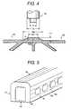
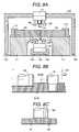
- Figure 8Ais a longitudinal cross-sectional view showing a joining apparatus of one embodiment according to the present invention.
- Figure 10is a longitudinal cross-sectional view showing a welded structure after a friction stir welding of the structure of Fig. 9.
- Figure 14is a longitudinal cross-sectional view showing the resulting structure after a thicker part of the structure shown in Fig. 13 is finished smoothly.
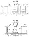
- Figure 18is a cross-sectional view taken along the line XVIII-XVIII of Figure 17.
- Each of the roof constructive body 42 and the floor constructive body 43is constituted similarly. Connections between the side constructive body 42 and the roof constructive body 41 and the floor constructive body 43 are carried out using an MIG (metal electrode inert gas) welding, etc.
- MIGmetal electrode inert gas
- an excessive part of the upper face joining region(a part extending outward from the faces of the general portions (non-thickened portions) of the plates 51 and 61)) is machined by, illustratively, a grinding machine, and it is performed to have the same plan face as the upper faces of the general portion of the plates 51 and 61. Since the upper face side is machined, it is possible to carry out easily the cutting working.
- FIG. 15 to Fig. 16An embodiment shown from Fig. 15 to Fig. 16 shows a case where the extruded frame members 37c and 38c, having the thickened parts 34b and 35b, are provided at a side of the ribs 39. With this structure, a side of a bed stand 36C becomes flat.
- a triangular-shaped groove 158is provided at an outer face of the thickened part 156 which is positioned between the end portion 150b of the extruded frame member 150 and the end portion 160b of the extruded frame member 160.
- This groove 158works a role of a positional mark for determining initially the position of the rotary body 70.
- This groove 158further works a role of a mark for the sensor.
Landscapes
- Engineering & Computer Science (AREA)
- Mechanical Engineering (AREA)
- Physics & Mathematics (AREA)
- Optics & Photonics (AREA)
- Electromagnetism (AREA)
- Pressure Welding/Diffusion-Bonding (AREA)
Abstract
Description
Claims (71)
- A friction stir welding method, comprising the stepsof:positioning adjacent to each other two members to bewelded together, a first end of one of the two members beingpositioned adjacent a first end of the other of the twomembers, said first end of at least one of the two membershaving a thickened part, thicker than a remaining part of saidat least one of said two metal members, said thickened partprotruding toward a tool for performing the friction stirwelding; andperforming friction stir welding with said tool, atsaid first ends of the two metal members, so as to weld thetwo members to each other.
- The friction stir welding method according to claim1, wherein after performing the friction stir welding,material of the members at the location of the thickened partis at a level higher than a surface of the remaining part ofthe member having the thickened part.
- The friction stir welding method according to claim1, wherein said tool is a rotary body which has twocylindrical portions, a first cylindrical portion, having afirst diameter, and a second cylindrical portion, extendingalong a same axis as the first cylindrical portion, having a second diameter larger than the first diameter, such that thefirst cylindrical portion projects from the second cylindricalportion; and wherein the step of performing friction stirwelding comprises (a) rotating the rotary body; (b) insertingthe rotary body such that the first cylindrical portion isinserted into a first region including the first ends of thetwo members to be welded, and the second cylindrical portionis inserted into a second region including at least part of athickness of the thickened part; and (c) moving relatively therotating rotary body with the first and second cylindricalportions inserted as in (b), along the adjacent two members,such that the first ends of the two members are weldedtogether so as to weld the two members.
- The friction stir welding method according to claim3, wherein said second region, into which the secondcylindrical portion is inserted, does not extend below a levelof an extension of a surface of said remaining part of said atleast one of said two members.
- The friction stir welding method according to claim3, wherein the adjacent two first ends of the two members arein contact with each other.
- The friction stir welding method according to claim3, wherein the adjacent two first ends of the two members arespaced from each other.
- The friction stir welding method according to claim6, wherein the adjacent two first ends of the two members arespaced up to 3mm from each other.
- The friction stir welding method according to claim1, wherein said thickened part has two sides, a first side atthe first end of the member having said thickened part and asecond side opposite the first side, and wherein the secondside extends to a surface of the remaining part of the metalmember having the thickened part, the second side making anangle of less than 90° with an extension of a surface of aremaining part of the member having the thickened part.
- The friction stir welding method according to claim8, wherein said angle is in a range of 15°-60°.
- The friction stir welding method according to claim1, wherein the two members are adapted to form an exposed partof a body, and wherein surfaces of the two members having hadthe thickened part protruding therefrom constitute exposedsurfaces of the body.
- The friction stir welding method according to claim10, wherein after performing the friction stir welding,material at the location of the thickened part is at a levelhigher than a surface of the remaining part of the memberhaving the thickened part, and wherein the method includes a further step, after performing the stir friction welding, ofmachining material at the location of the thickened part suchthat a surface at the location of the thickened part is atsubstantially a same level as the surface of the remainingpart of the metal member having the thickened part.
- The friction stir welding method according to claim1, wherein after performing the friction stir welding,material at the location of the thickened part is at a levelhigher than a surface of a remaining part of the metal memberhaving the thickened part, and wherein the method includes afurther step, after performing the stir friction welding, ofmachining material at the location of the thickened part suchthat a surface at the location of the thickened part is atsubstantially a same level as the surface of the remainingpart of the member having the thickened part.
- The friction stir welding method according to claim1, wherein, in a product using the two members weldedtogether, surfaces of the two members having had the thickenedparts protruding therefrom are concealed surfaces in theproduct.
- The friction stir welding method according to claim1, wherein each of the two members has said thickened part.
- The friction stir welding method according to claim 14, wherein said tool is a rotary body which has twocylindrical portions, a first cylindrical portion, having afirst diameter, and a second cylindrical portion, extendingalong a same axis as the first cylindrical portion, having asecond diameter larger than the first diameter, such that thefirst cylindrical portion projects from the second cylindricalportion; and wherein the step of performing friction stirwelding comprises (a) rotating the rotary body; (b) insertingthe rotary body such that the first cylindrical portion isinserted into a first region including the first ends of thetwo members to be welded, and the second cylindrical portionis inserted into a second region including at least part of athickness of the thickened part; and (c) moving relatively therotating rotary body with the first and second cylindricalportions positioned as in (b), along the adjacent two members,such that the first ends of the two members are weldedtogether so as to weld the two members.
- The friction stir welding method according to claim14, wherein said second region, into which the secondcylindrical portion is inserted, does not extend below a levelof an extension of a surface of remaining parts of each of thetwo members other than the thickened parts.
- The friction stir welding method according to claim14, wherein thickened parts of the two members are placedadjacent each other.
- The friction stir welding method according to claim17, wherein the thickened parts of the two members protrude toa same height over the surface of the remaining parts of thetwo members, and in positioning the two members adjacent eachother the thickened parts of the two members are located at asame level, whereby the remaining parts of each of the twomembers are at a same level.
- The friction stir welding method according to claim17, wherein each thickened part has two sides, a first side atthe first end of the member having said thickened part and asecond side opposite the first side, and wherein the secondside is sloped to a surface of the remaining part of themember having the respective thickness part.
- Product formed by the method of claim 18.
- Product formed by the method of claim 14.
- Product formed by the method of claim 13.
- Product formed by the method of claim 12.
- Product formed by the method of claim 11.
- Product formed by the method of claim 1.
- A friction stir welding method, comprising the stepsof:positioning two members adjacent to each other, eachof the two members being comprised of two parallel plates andplates connecting the two parallel plates, each of the twoparallel plates of at least one of the two members having athickened part at an end thereof, the thickened part extendingin a direction away from the other of the two parallel platesof this member, the thickened part of each of the two parallelplates of one of the two members being positioned adjacent athickened part of the parallel plates of the other of the twomembers, whereby thickened parts of one of the two members arelocated adjacent thickened parts of the other of the two metalmembers at both surfaces of the members;performing friction stir welding at substantially asame time at both surfaces of the members;after performing the friction stir welding, wherebya remaining portion of the thickened parts remains, machiningsaid remaining portion on one of the surfaces of the members.
- The friction stir welding method according to claim26, wherein when performing the friction stir welding the twomembers are positioned horizontally, with the surfaces of themembers respectively being upper and lower surfaces of thehorizontally positioned members, and wherein in said machiningonly the remaining portion on the upper surface is machined.
- The friction stir welding method according to claim26, wherein the plates connecting the two parallel plates ofone of the two members include a plate adjacent an end of saidone of the two members, extending between corresponding endsof the two parallel plates of said one of the two members, atthe thickened parts.
- Product formed by the method of claim 28.
- Product formed by the method of claim 26.
- A friction stir welding method, comprising the stepsof:positioning adjacent to each other two members to bewelded together, a first end of one of the two members beingpositioned adjacent a first end of the other of the twomembers, the first end of at least one of the two membershaving a thickened part, thicker than a remaining part of theat least one of the two members, said thickened partprotruding from a side of the at least one of the two metalmembers;performing friction stir welding at said first endsof the two members, so as to weld the two metal memberstogether, by applying a rotary body to the thickened part; andmachining the side of the at least one of the twomembers that had the thickened part protruding therefrom, saidmachining being carried out by a cutting tool that moves together with a rotary body used for performing the frictionstir welding.
- The friction stir welding method according to claim31, wherein when performing the friction stir welding the twomembers are positioned horizontally, and the side from whichthe thickened part protrudes faces upward.
- A friction stir welding method, comprising:positioning first and second members adjacent toeach other such that an extruded part of the first member,constituting an end portion of the first member, overlaps anend portion of a first surface of the second member, such thatthe extruded part extends to a higher level than the firstsurface of the second member, so as to protrude toward a toolfor performing the friction stir welding; andperforming the friction stir welding with said tool,at the end portions of the first and second members, so as toweld the first and second members to each other.
- The friction stir welding method according to claim33, wherein the first member further comprises a thickenedpart adjacent the extruded part, in a direction away from anedge of the first member, the thickened part protruding from aremaining surface of the first member, other than thethickened part and the extruded part; and wherein the frictionstir welding is performed at the thickened part and at the end portions of the first and second members.
- The friction stir welding method according to claim34, wherein the thickened part is positioned adjacent the endportion of the second metal member, and protrudes to a samelevel as the extruded part.
- The friction stir welding method according to claim34, wherein said tool is a rotary body which has twocylindrical portions, a first cylindrical portion, having afirst diameter, and a second cylindrical portion, extendingalong a same axis as the first cylindrical portion, having asecond diameter larger than the first diameter, such that thefirst cylindrical portion projects from the second cylindricalportion; and wherein the step of performing friction stirwelding comprises (a) rotating the rotary body; (b) insertingthe rotary body such that the first cylindrical portion isinserted into a first region including the end portion of thesecond member and a part of the first member adjacent thereto,and the second cylindrical portion is inserted into a secondregion including at least part of a thickness of the extrudedpart but not more than a full thickness thereof; and (c)moving relatively the rotating rotary body with the first andsecond cylindrical portions inserted as in (b), along theadjacent first and second members, so as to weld the first andsecond members together.
- The friction stir welding method according to claim33, wherein said tool is a rotary body which has twocylindrical portions, a first cylindrical portion, having afirst diameter, and a second cylindrical portion, extendingalong a same axis as the first cylindrical portion, having asecond diameter larger than the first diameter, such that thefirst cylindrical portion projects from the second cylindricalportion; and wherein the step of performing friction stirwelding comprises (a) rotating the rotary body; (b) insertingthe rotary body such that the first cylindrical portion isinserted into a first region including the end portion of thesecond member and a part of the first member adjacent thereto,and the second cylindrical portion is inserted into a secondregion including at least part of a thickness of the extrudedpart but not more than a full thickness thereof; and (c)moving relatively the rotating rotary body with the first andsecond cylindrical portions inserted as in (b), along theadjacent first and second members, so as to weld the first andsecond members together.
- A friction stir welding method, comprising:positioning a first member adjacent a second member,the first member having a length direction orthogonal to alength direction of the second member, an extruded part,constituting an end portion of the first member, overlappingan end portion of a first surface of the second member suchthat the extruded part of the first member extends to a higher level than the first surface of the second member, so as toprotrude toward a tool for performing the friction stirwelding; andperforming the friction stir welding with said tool,at the end portions of the first and second members, so as toweld the first and second metal members to each other.
- The friction stir welding method according to claim38, wherein said tool is a rotary body which has twocylindrical portions, a first cylindrical portion, having afirst diameter, and a second cylindrical portion, extendingalong a same axis as the first cylindrical portion, having asecond diameter larger than the first diameter, such that thefirst cylindrical portion projects from the second cylindricalportion; and wherein the step of performing friction stirwelding comprises (a) rotating the rotary body; (b) insertingthe rotary body such that the first cylindrical portion isinserted into a first region including the end portion of thesecond member and a part of the first member adjacent thereto,and the second cylindrical portion is inserted into a secondregion including at least part of a thickness of the extrudedpart but not more than a full thickness thereof; and (c)moving relatively the rotating rotary body with the first andsecond cylindrical portions inserted as in (b), along theadjacent first and second members, so as to weld the first andsecond members together.
- A friction stir welding method, comprising:positioning a first member adjacent a second member,the first member having a length direction orthogonal to alength direction of the second member, the first member havingtwo sides extending in the length direction thereof and endsextending orthogonally to said sides, the second member havingsides extending in the length direction thereof and endsextending orthogonally to the sides of the second member, oneside of the first metal member having an extruded part,positioned to overlap a region of the second member extendingfrom one of the ends thereof, such that the extruded partextends to a higher level than a surface of the second memberso as to protrude toward a tool for performing the frictionstir welding, the other side of the first metal member havinga first thickened part protruding toward said tool; andperforming the friction stir welding with said tool,at the extruded part of the first member and said region ofthe second metal member overlapped thereby, and at a part ofthe first metal member adjacent said region of the secondmember, so as to weld the first and second members to eachother.
- The friction stir welding method according to claim40, wherein the part of the first member adjacent said regionof the second member is a second thickened part, protrudingfrom the first member to a same level as the extruded part.
- The friction stir welding method according to claim40, wherein said tool is a rotary body which has twocylindrical portions, a first cylindrical portion, having afirst diameter, and a second cylindrical portion, extendingalong a same axis as the first cylindrical portion, having asecond diameter larger than the first diameter, such that thefirst cylindrical portion projects from the second cylindricalportion; and wherein the step of performing friction stirwelding comprises (a) rotating the rotary body; (b) insertingthe rotary body such that the first cylindrical portion isinserted into a first region including the end portion of asecond member and a part of the first member adjacent thereto,and the second cylindrical portion is inserted into a secondregion including at least part of a thickness of the extrudedpart but not more than a full thickness thereof; and (c)moving relatively the rotating rotary body with the first andsecond cylindrical portions inserted as in (b), along theadjacent first and second members, so as to weld the first andsecond members together.
- A joined structure, comprising:two members each comprised of two parallel platesand plates for connecting the two parallel plates, theparallel plates respectively forming first and second sides ofthe joined structure, end portions of the two members havingbeen joined in a joining region, said joining region beingprovided at both the first and second sides of the joined structure, whereby one of the two parallel plates of one ofthe two members is joined to one of the two parallel plates ofthe other of the two members at ends thereof, and the other ofthe two parallel plates of one of the two members is joined tothe other of the parallel plates of the other of the twomembers at ends thereof,wherein an outer surface of the joining region atthe first side of the joined structure is flat, and wherein anouter surface of the joining region at the second side of thejoined structure has a thick part, which protrudes from aremaining part of the second side of the joined structure.
- The joined structure according to claim 43, whereinthe end portions of the two members have been joined byfriction stir welding.
- The joined structure according to claim 43, whereinthe thick part of the joining region of the second side has adent portion, extending into the thick part.
- The joined structure according to claim 45, whereinsaid dent portion extends to a level that still protrudes fromthe remaining part of the second side of the joined structure.
- The joined structure according to claim 43, whereinthe thick part of the joining region of the second side has adent portion and raised portions at sides of the dent portion.
- The joined structure according to claim 47, whereinsaid dent portion extends to a level that still protrudes fromthe remaining part of the second side of the joined structure.
- The joined structure according to claim 48, whereinthe end portions of the two members have been joined byfriction stir welding.
- The joined structure according to claim 47, whereinsaid raised portions at the sides of the dent portion eachprotrude a substantially same distance from the remaining partof the second side of the joined structure.
- The joined structure according to claim 43, saidjoined structure forming part of a vehicle body, the firstside of the joined structure forming an outer side of thevehicle body.
- The joined structure according to claim 51, whereinsaid vehicle body is a railroad car.
- A joined structure, comprising:two members, each comprised of two parallel platesand a plurality of further plates for connecting the twoparallel plates, the parallel plates respectively formingfirst and second sides of the joined structure;an end portion of each of the two parallel plates of one of the two members being friction stir welded respectivelyto an end portion of each of the two parallel plates of theother of the two members, forming respective friction stirwelded portions at the first and second sides of the joinedstructure,wherein, at one of the friction stir weldedportions, at one of the first and second sides, there is athick part protruding from the parallel plates, in a directionextending away from the further plates.
- A joined structure, comprising:two members, each of the two members having a plateand a plurality of ribs extending away from one side of theplate,end portions of the plates of the two members beingfriction stir welded to each other at a friction stir weldedportion,wherein said friction stir welded portion has athick part protruding from the plates in a direction extendingaway from the ribs.
- A joined structure, comprising:first and second frame members, each comprised oftwo parallel plates and a further plate connecting between thetwo parallel plates, each of the frame members extending in alength direction, the length direction of the first framemember being orthogonal to the length direction of the second frame member, the two parallel plates of the first framemember having sides extending in the length direction of thefirst frame member and ends extending orthogonally thereto,the two parallel plates of the second frame member havingsides extending in the length direction of the second framemember and ends extending orthogonally thereto; andend portions of the two parallel plates of the firstframe member, extending from an end thereof, being welded toside portions of the two parallel plates of the second framemember, extending from a side thereof, at weld portions;wherein, in a weld portion between parallel plates,of the parallel plates of the first and second frame members,at one surface of the joined structure, the surface is flatwith respect to surfaces of the respective parallel plates;andwherein, in a weld portion between parallel plates,of the parallel plates of the first and second frame members,at another surface of the joined structure, the weld portionprotrudes from surfaces of the respective parallel plates, ina direction away from the further plate.
- A joined structure according to claim 55, whereinsaid joined structure is part of a vehicle; and wherein thefirst frame member forms a structural part between an entranceand exit part of the vehicle and a window opening thereof, andthe second frame member forms the window opening.
- A joined structure according to claim 56, whereinsaid vehicle is a railway vehicle.
- A joined structure according to claim 55, whereinsaid joined structure is part of a vehicle, and wherein thefirst frame member forms a structural part between twowindows, and the second frame member forms an opening for oneof the two windows.
- A frame member, to be joined to another frame memberto form a joined structure, comprising:a plate member, having first and second opposedsurfaces; anda plurality of ribs extending from the first surfaceof the plate member,wherein the plate member has first and second endportions respectively at opposite ends of the plate member, atleast one of the first and second end portions being athickened portion that protrudes from the second surface ofthe plate member, away from the plurality of ribs.
- The frame member according to claim 59, wherein boththe first and second end portions are said thickened portions.
- A frame member, to be joined to another frame memberto form a joined structure, comprising:a plate member, having first and second opposed surfaces; anda plurality of ribs extending from the first surfaceof the plate member,wherein the plate member has first and second endportions respectively at opposite ends of the plate member, atleast one of the first and second end portions being athickened portion that protrudes from the second surface ofthe plate member, away from the plurality of ribs, thethickened portion having opposite first and second sidesrespectively adjacent to an edge of the plate member andfarthest from said edge, said second side being sloped inextending from an apex of the thickened portion toward aremainder of the second surface of the plate member, otherthan the thickened portion.
- A frame member, to be joined to another frame memberto form a joined structure, comprising:a plate member, having first and second opposedsurfaces; anda plurality of ribs extending from the first surfaceof the plate member,wherein the plate member has first and second endportions respectively at opposite ends of the plate member, atleast one of the first and second end portions being athickened portion that protrudes from the first surface of theplate member, in a direction that the plurality of ribsextend.
- The frame member according to claim 62, wherein thethickened portion has opposed first and second sides,respectively adjacent to an edge of the plate member andfarthest from said edge, said second side being sloped inextending from an apex of the thickened portion toward thefirst surface of the plate member.
- A frame member, to be joined to another frame memberto form a joined structure, comprising:a pair of parallel plates and a further plateconnecting between the pair of parallel plates,wherein each of the pair of parallel plates hasfirst and second end portions respectively at opposite ends,at least one of the first and second end portions of each ofthe pair of parallel plates having a thickened portion, thethickened portion protruding from the parallel plates in adirection away from the further plate, andwherein each thickened portion has opposed first andsecond sides, respectively adjacent to an edge of a parallelplate and farthest from said edge, said second side beingsloped in extending from an apex of the thickened portiontoward a remainder of the parallel plate.
- A frame member, to be joined to another frame memberto form a joined structure, comprising:a plate, having a plurality of ribs extending fromonly one side of the plate,wherein said plate has a thickened portion whichprotrudes from the plate, in a direction away from theplurality of ribs, and an extruded part forming an edgeportion of the plate, the thickened portion including, in athickness direction, a first portion which corresponds to athickness of a remainder of the plate adjacent the thickenedportion, and a second portion having a thickness so as toprotrude from the plate.
- The frame member according to claim 65, wherein saidextruded part is adapted to overlap an adjacent frame member,and extends from the second portion of the thickened portionand substantially not from the first portion of the thickenedportion.
- The frame member according to claim 65, wherein thethickened portion and the extruded part extend along a lengthof the plate.
- The frame member according to claim 65, wherein thethickened portion has a thickened part side extending from anapex of the thickened part to a surface of the remainder ofthe plate adjacent the thickened portion, the thickened partside being sloped.
- A frame member, to be joined to another frame memberto form a joined structure, comprising:two plates, and at least one further plate connectedbetween the two plates,wherein each of the two plates has a thickenedportion which protrudes from a respective plate in a directionaway from the at least one further plate, and an extruded partforming an edge portion of the respective plate, eachthickened portion including, in a thickness direction, a firstportion which corresponds to a thickness of a remainder of therespective plate adjacent the thickened portion, and a secondportion having a thickness so as to protrude from the plate.
- The frame member according to claim 69, wherein saidextruded part is adapted to overlap an adjacent frame member,and extends from the second portion of the thickened portionand substantially not from the first portion of the thickenedportion.
- The frame member according to claim 69, wherein thethickened portion has a thickened part side extending from anapex of the thickened part to a surface of the remainder ofthe plate adjacent the thickened portion, the thickened partside being sloped.
Priority Applications (11)
| Application Number | Priority Date | Filing Date | Title |
|---|---|---|---|
| EP04002655AEP1442822B1 (en) | 1997-07-23 | 1998-02-18 | Friction stir welding method, frame members used therein, and product thereby |
| EP04002654AEP1442867B1 (en) | 1997-07-23 | 1998-02-18 | Friction stir welding method, frame members used therein, and product formed thereby |
| EP04002653AEP1442821B1 (en) | 1997-07-23 | 1998-02-18 | A joined structure of two members joined by a friction stir welded welding portion |
| EP04002657AEP1442823B1 (en) | 1997-07-23 | 1998-02-18 | Friction stir welding method, frame members used therein, and product formed thereby |
| EP04011030AEP1462205B1 (en) | 1997-07-23 | 1998-02-18 | A combination of first and a second extruded frame members to be joined to each other by friction stir welding |
| EP04002662AEP1442828B1 (en) | 1997-07-23 | 1998-02-18 | Friction stir welding method |
| EP04002660AEP1442826B1 (en) | 1997-07-23 | 1998-02-18 | Friction stir welded joint structure. |
| EP04002661AEP1442827B1 (en) | 1997-07-23 | 1998-02-18 | Friction stir welded product |
| EP04002659AEP1442825B9 (en) | 1997-07-23 | 1998-02-18 | Friction stir welding method |
| EP04002658AEP1442824B1 (en) | 1997-07-23 | 1998-02-18 | Friction stir welding method, frame members used therein, and product formed thereby |
| EP04002656AEP1442868B1 (en) | 1997-07-23 | 1998-02-18 | Friction stir welding method, frame members used therein, and product formed thereby |
Applications Claiming Priority (3)
| Application Number | Priority Date | Filing Date | Title |
|---|---|---|---|
| JP19675997 | 1997-07-23 | ||
| JP196759/97 | 1997-07-23 | ||
| JP19675997 | 1997-07-23 |
Related Child Applications (11)
| Application Number | Title | Priority Date | Filing Date |
|---|---|---|---|
| EP04011030ADivisionEP1462205B1 (en) | 1997-07-23 | 1998-02-18 | A combination of first and a second extruded frame members to be joined to each other by friction stir welding |
| EP04002660ADivisionEP1442826B1 (en) | 1997-07-23 | 1998-02-18 | Friction stir welded joint structure. |
| EP04002657ADivisionEP1442823B1 (en) | 1997-07-23 | 1998-02-18 | Friction stir welding method, frame members used therein, and product formed thereby |
| EP04002653ADivisionEP1442821B1 (en) | 1997-07-23 | 1998-02-18 | A joined structure of two members joined by a friction stir welded welding portion |
| EP04002662ADivisionEP1442828B1 (en) | 1997-07-23 | 1998-02-18 | Friction stir welding method |
| EP04002655ADivisionEP1442822B1 (en) | 1997-07-23 | 1998-02-18 | Friction stir welding method, frame members used therein, and product thereby |
| EP04002658ADivisionEP1442824B1 (en) | 1997-07-23 | 1998-02-18 | Friction stir welding method, frame members used therein, and product formed thereby |
| EP04002659ADivisionEP1442825B9 (en) | 1997-07-23 | 1998-02-18 | Friction stir welding method |
| EP04002654ADivisionEP1442867B1 (en) | 1997-07-23 | 1998-02-18 | Friction stir welding method, frame members used therein, and product formed thereby |
| EP04002656ADivisionEP1442868B1 (en) | 1997-07-23 | 1998-02-18 | Friction stir welding method, frame members used therein, and product formed thereby |
| EP04002661ADivisionEP1442827B1 (en) | 1997-07-23 | 1998-02-18 | Friction stir welded product |
Publications (3)
| Publication Number | Publication Date |
|---|---|
| EP0893189A2true EP0893189A2 (en) | 1999-01-27 |
| EP0893189A3 EP0893189A3 (en) | 2002-01-02 |
| EP0893189B1 EP0893189B1 (en) | 2004-05-12 |
Family
ID=16363157
Family Applications (12)
| Application Number | Title | Priority Date | Filing Date |
|---|---|---|---|
| EP04011030AExpired - LifetimeEP1462205B1 (en) | 1997-07-23 | 1998-02-18 | A combination of first and a second extruded frame members to be joined to each other by friction stir welding |
| EP04002653AExpired - LifetimeEP1442821B1 (en) | 1997-07-23 | 1998-02-18 | A joined structure of two members joined by a friction stir welded welding portion |
| EP04002659AExpired - LifetimeEP1442825B9 (en) | 1997-07-23 | 1998-02-18 | Friction stir welding method |
| EP04002662AExpired - LifetimeEP1442828B1 (en) | 1997-07-23 | 1998-02-18 | Friction stir welding method |
| EP04002655AExpired - LifetimeEP1442822B1 (en) | 1997-07-23 | 1998-02-18 | Friction stir welding method, frame members used therein, and product thereby |
| EP04002654AExpired - LifetimeEP1442867B1 (en) | 1997-07-23 | 1998-02-18 | Friction stir welding method, frame members used therein, and product formed thereby |
| EP04002660AExpired - LifetimeEP1442826B1 (en) | 1997-07-23 | 1998-02-18 | Friction stir welded joint structure. |
| EP04002661AExpired - LifetimeEP1442827B1 (en) | 1997-07-23 | 1998-02-18 | Friction stir welded product |
| EP98301177AExpired - LifetimeEP0893189B1 (en) | 1997-07-23 | 1998-02-18 | Friction stir welding method. |
| EP04002657AExpired - LifetimeEP1442823B1 (en) | 1997-07-23 | 1998-02-18 | Friction stir welding method, frame members used therein, and product formed thereby |
| EP04002658AExpired - LifetimeEP1442824B1 (en) | 1997-07-23 | 1998-02-18 | Friction stir welding method, frame members used therein, and product formed thereby |
| EP04002656AExpired - LifetimeEP1442868B1 (en) | 1997-07-23 | 1998-02-18 | Friction stir welding method, frame members used therein, and product formed thereby |
Family Applications Before (8)
| Application Number | Title | Priority Date | Filing Date |
|---|---|---|---|
| EP04011030AExpired - LifetimeEP1462205B1 (en) | 1997-07-23 | 1998-02-18 | A combination of first and a second extruded frame members to be joined to each other by friction stir welding |
| EP04002653AExpired - LifetimeEP1442821B1 (en) | 1997-07-23 | 1998-02-18 | A joined structure of two members joined by a friction stir welded welding portion |
| EP04002659AExpired - LifetimeEP1442825B9 (en) | 1997-07-23 | 1998-02-18 | Friction stir welding method |
| EP04002662AExpired - LifetimeEP1442828B1 (en) | 1997-07-23 | 1998-02-18 | Friction stir welding method |
| EP04002655AExpired - LifetimeEP1442822B1 (en) | 1997-07-23 | 1998-02-18 | Friction stir welding method, frame members used therein, and product thereby |
| EP04002654AExpired - LifetimeEP1442867B1 (en) | 1997-07-23 | 1998-02-18 | Friction stir welding method, frame members used therein, and product formed thereby |
| EP04002660AExpired - LifetimeEP1442826B1 (en) | 1997-07-23 | 1998-02-18 | Friction stir welded joint structure. |
| EP04002661AExpired - LifetimeEP1442827B1 (en) | 1997-07-23 | 1998-02-18 | Friction stir welded product |
Family Applications After (3)
| Application Number | Title | Priority Date | Filing Date |
|---|---|---|---|
| EP04002657AExpired - LifetimeEP1442823B1 (en) | 1997-07-23 | 1998-02-18 | Friction stir welding method, frame members used therein, and product formed thereby |
| EP04002658AExpired - LifetimeEP1442824B1 (en) | 1997-07-23 | 1998-02-18 | Friction stir welding method, frame members used therein, and product formed thereby |
| EP04002656AExpired - LifetimeEP1442868B1 (en) | 1997-07-23 | 1998-02-18 | Friction stir welding method, frame members used therein, and product formed thereby |
Country Status (6)
| Country | Link |
|---|---|
| US (14) | US6050474A (en) |
| EP (12) | EP1462205B1 (en) |
| JP (5) | JP3070735B2 (en) |
| KR (11) | KR100428535B1 (en) |
| CN (15) | CN1292870C (en) |
| DE (12) | DE69840950D1 (en) |
Cited By (33)
| Publication number | Priority date | Publication date | Assignee | Title |
|---|---|---|---|---|
| WO2001083153A1 (en)* | 2000-04-28 | 2001-11-08 | Mazda Motor Corporation | Method of processing metal members |
| US6315187B1 (en)* | 1998-09-29 | 2001-11-13 | Hitachi, Ltd. | Friction stir welding method |
| EP1132167A3 (en)* | 2000-03-06 | 2001-12-05 | Hitachi, Ltd. | Friction stir welding |
| US6352193B1 (en) | 2000-08-01 | 2002-03-05 | General Electric Company | Apparatus for joining electrically conductive materials |
| US6378264B1 (en) | 1999-05-28 | 2002-04-30 | Hitachi, Ltd. | Structure body and method of manufacture thereof |
| US6419144B2 (en)* | 1997-07-23 | 2002-07-16 | Hitachi, Ltd. | Method of forming structural body using friction stir welding, and structural body formed |
| US6461072B2 (en) | 2000-01-24 | 2002-10-08 | Hitachi, Ltd. | Structure body for use in friction stir welding |
| US6599641B1 (en)* | 2000-01-27 | 2003-07-29 | Hitachi, Ltd. | Structural body formed by friction stir welding of hollow extruded frame members |
| DE10226526A1 (en)* | 2002-06-14 | 2003-08-07 | Daimler Chrysler Ag | Running gear frame has interconnected frame sections with at least one frame section seam as a friction stir welded seam which extends three-dimensionally, and at least two frame sections are differently constructed |
| EP1057575A3 (en)* | 1999-05-28 | 2003-08-13 | Hitachi, Ltd. | A method of manufacturing a structural body and a apparatus therefor |
| US6622904B2 (en)* | 2000-11-17 | 2003-09-23 | Hitachi, Ltd. | Friction stir bonding method |
| US6648206B2 (en) | 2000-05-08 | 2003-11-18 | Tracey W. Nelson | Friction stir welding using a superabrasive tool |
| EP1201347A3 (en)* | 2000-10-27 | 2004-05-12 | Hitachi, Ltd. | Compound machining apparatus and friction stir welding method |
| US6984455B2 (en)* | 2001-01-17 | 2006-01-10 | Hitachi, Ltd. | Friction stir welding method, and method for manufacturing car body |
| EP1698425A1 (en)* | 2001-04-16 | 2006-09-06 | Hitachi, Ltd. | Friction stir welding method, and hollow shape member for friction stir welding |
| US7225968B2 (en) | 2003-08-04 | 2007-06-05 | Sii Megadiamond, Inc. | Crack repair using friction stir welding on materials including metal matrix composites, ferrous alloys, non-ferrous alloys, and superalloys |
| US7270257B2 (en) | 2003-01-30 | 2007-09-18 | Sii Megadiamond, Inc. | Out-of-position friction stir welding of high melting temperature alloys |
| US7530486B2 (en) | 2003-05-05 | 2009-05-12 | Sii Megadiamond, Inc. | Applications of friction stir welding using a superabrasive tool |
| WO2009070707A3 (en)* | 2007-11-28 | 2009-07-30 | Frank S Inr Inc | Methods and apparatus for forming tubular strings |
| US7608296B2 (en) | 2001-06-12 | 2009-10-27 | Brigham Young University | Anvil for friction stir welding high temperature materials |
| US7651018B2 (en) | 2004-10-05 | 2010-01-26 | Sii Megadiamond | Expandable mandrel for use in friction stir welding |
| US8056797B2 (en) | 2005-10-05 | 2011-11-15 | Megastir Technologies | Expandable mandrel for use in friction stir welding |
| US8186561B2 (en) | 2004-03-24 | 2012-05-29 | Megastir Technologies, LLC | Solid state processing of hand-held knife blades to improve blade performance |
| WO2013057373A1 (en)* | 2011-10-17 | 2013-04-25 | Oy Kwh Pipe Ab | Method of producing a plate-like construction with a double-wall structure |
| WO2013057374A1 (en)* | 2011-10-17 | 2013-04-25 | Oy Kwh Pipe Ab | Three-dimensional constructions |
| US8770464B2 (en) | 2008-11-26 | 2014-07-08 | Airbus Operations Gmbh | Method for producing overlapping weld joints and overlapping weld joint |
| US8955734B2 (en) | 2004-05-21 | 2015-02-17 | Smith International, Inc. | Ball hole welding using the friction stir welding (FSW) process |
| GB2526122A (en)* | 2014-05-14 | 2015-11-18 | Acergy France SAS | Fabrication of pipe strings using friction stir welding |
| US9242308B2 (en) | 2009-11-02 | 2016-01-26 | Megastir Technologies Llc | Out of position friction stir welding of casing and small diameter tubing or pipe |
| WO2016138061A1 (en)* | 2015-02-24 | 2016-09-01 | AlumaBridge, LLC | Modular bridge deck system consisting of hollow extruded aluminum elements |
| NO20161580A1 (en)* | 2016-09-30 | 2018-04-02 | Eivind Berg | A device for secure storing of items |
| WO2020249284A1 (en)* | 2019-06-13 | 2020-12-17 | Sms Group Gmbh | Fixing a strip end segment of a metal strip coil to an adjacent strip winding |
| DE102013106692B4 (en) | 2012-06-29 | 2023-05-04 | Suzuki Motor Corporation | FRICTION STIR WELDING PROCESS FOR METAL WORKPIECE |
Families Citing this family (227)
| Publication number | Priority date | Publication date | Assignee | Title |
|---|---|---|---|---|
| NO954273D0 (en)* | 1995-10-26 | 1995-10-26 | Norsk Hydro As | Wheels Wheel |
| CN1165403C (en)* | 1996-03-19 | 2004-09-08 | 株式会社日立制作所 | Components for friction welding |
| JP4406092B2 (en)* | 1997-05-16 | 2010-01-27 | エサブ アクチボラゲット | Welding assembly for rotary friction welding |
| GB9713209D0 (en)* | 1997-06-20 | 1997-08-27 | British Aerospace | Friction welding metal components |
| JP3589863B2 (en)* | 1997-07-23 | 2004-11-17 | 株式会社日立製作所 | Structure and friction stir welding method |
| SE9704800D0 (en)* | 1997-12-19 | 1997-12-19 | Esab Ab | Device for welding |
| JP3333728B2 (en)* | 1997-12-25 | 2002-10-15 | 東海ゴム工業株式会社 | Bush mounting member and method of manufacturing the same |
| US6290117B1 (en)* | 1998-02-17 | 2001-09-18 | Hitachi, Ltd. | Friction stir welding method and friction stir welding apparatus |
| JP3420502B2 (en)* | 1998-06-16 | 2003-06-23 | 株式会社日立製作所 | Structure |
| US6745929B1 (en)* | 1998-06-16 | 2004-06-08 | Hitachi, Ltd. | Method of manufacturing structural body and structural body |
| JP4004150B2 (en)* | 1998-09-11 | 2007-11-07 | 本田技研工業株式会社 | Rear cushion bracket mounting structure |
| ES2281134T3 (en)* | 1998-09-28 | 2007-09-16 | Hitachi, Ltd. | BODYWORK. |
| US7748233B2 (en) | 1998-12-23 | 2010-07-06 | S.I.P. Technologies L.L.C. | Sanitized water dispenser |
| US7175054B2 (en)* | 1998-12-23 | 2007-02-13 | S.I.P. Technologies, Llc | Method and apparatus for disinfecting a refrigerated water cooler reservoir |
| US6247633B1 (en)* | 1999-03-02 | 2001-06-19 | Ford Global Technologies, Inc. | Fabricating low distortion lap weld construction |
| WO2000056497A1 (en)* | 1999-03-24 | 2000-09-28 | Framatome Anf Gmbh | Method and device for welding two work pieces |
| JP3459193B2 (en)* | 1999-05-26 | 2003-10-20 | 株式会社日立製作所 | Method of repairing friction stir welding and method of manufacturing railway vehicle |
| JP3481501B2 (en)* | 1999-05-28 | 2003-12-22 | 株式会社日立製作所 | Structure and method of manufacturing the same |
| JP3868695B2 (en)* | 1999-05-28 | 2007-01-17 | 株式会社日立製作所 | Manufacturing method of structure |
| TW449519B (en) | 1999-05-31 | 2001-08-11 | Hitachi Ltd | A manufacturing method of a structure body |
| JP2000343245A (en)* | 1999-05-31 | 2000-12-12 | Hitachi Ltd | How to make a structure |
| AU7475200A (en)* | 1999-09-03 | 2001-04-10 | Lockheed Martin Corporation | Friction stir welding as a rivet replacement technology |
| JP3563003B2 (en)* | 1999-09-30 | 2004-09-08 | 株式会社日立製作所 | Friction stir welding method for structures |
| DE19957136C1 (en)* | 1999-11-18 | 2001-02-08 | Geesthacht Gkss Forschung | Friction welding appts has a projecting and rotating pin to act on the workpiece materials at the welding zone to follow the welding line and soften the materials to fuse together and bond sheet plates with complex shapes |
| JP3459210B2 (en)* | 1999-11-24 | 2003-10-20 | 株式会社日立製作所 | Friction stir welding method |
| US6722286B2 (en)* | 1999-12-14 | 2004-04-20 | Hitachi, Ltd. | Structure and railway car |
| US6299050B1 (en)* | 2000-02-24 | 2001-10-09 | Hitachi, Ltd. | Friction stir welding apparatus and method |
| JP3589930B2 (en)* | 2000-02-25 | 2004-11-17 | 株式会社日立製作所 | Friction stir welding method |
| US6237835B1 (en)* | 2000-02-29 | 2001-05-29 | The Boeing Company | Method and apparatus for backing up a friction stir weld joint |
| US6367681B1 (en)* | 2000-04-04 | 2002-04-09 | The Boeing Company | Friction stir welding apparatus and method |
| JP2001293582A (en) | 2000-04-13 | 2001-10-23 | Nissan Motor Co Ltd | Aluminum links |
| JP3400409B2 (en)* | 2000-04-28 | 2003-04-28 | マツダ株式会社 | Joining method and joining device |
| JP3429475B2 (en)* | 2000-05-08 | 2003-07-22 | 川崎重工業株式会社 | Spot joining apparatus and spot joining method |
| JP3781099B2 (en)* | 2000-06-02 | 2006-05-31 | トヨタ自動車株式会社 | Hollow product, fluid processing system, and method for joining hollow members |
| JP3274453B2 (en)* | 2000-06-05 | 2002-04-15 | 川崎重工業株式会社 | Joint failure detection method in friction stir welding |
| JP4467723B2 (en)* | 2000-06-30 | 2010-05-26 | 昭和電工株式会社 | Friction stir welding method |
| US6619533B1 (en)* | 2000-09-22 | 2003-09-16 | Tower Automotive Technology Products, Inc. | Multi-piece extruded link arm |
| JP3538378B2 (en)* | 2000-10-27 | 2004-06-14 | 株式会社日立製作所 | Friction stir welding method |
| JP3553012B2 (en)* | 2000-11-17 | 2004-08-11 | 株式会社日立製作所 | Friction stir welding method |
| JP4723081B2 (en)* | 2000-11-29 | 2011-07-13 | 株式会社日立製作所 | Manufacturing method of structure |
| DE10059847B4 (en)* | 2000-11-30 | 2005-07-14 | Webasto Ag | Heat exchanger for vehicle heaters |
| US6769595B2 (en)* | 2000-12-20 | 2004-08-03 | Alcoa Inc. | Friction plunge riveting |
| US20030111514A1 (en)* | 2001-01-23 | 2003-06-19 | Naoki Miyanagi | Method of friction welding, and frictionally welded structure |
| JP2002239756A (en)* | 2001-02-14 | 2002-08-28 | Nissan Motor Co Ltd | Friction stir welding method and apparatus |
| JP2002273579A (en)* | 2001-03-15 | 2002-09-25 | Hitachi Ltd | Method of joining iron-based material and its structure |
| US6550397B2 (en) | 2001-03-27 | 2003-04-22 | Hitachi, Ltd. | Car body |
| US6582539B2 (en)* | 2001-06-08 | 2003-06-24 | Lockheed Martin Corporation | Method for making large composite structures without use of an autoclave |
| JP3471338B2 (en)* | 2001-07-30 | 2003-12-02 | 川崎重工業株式会社 | Friction stir welding equipment |
| JP3751236B2 (en)* | 2001-08-24 | 2006-03-01 | 株式会社日立製作所 | Friction stir welding method |
| JP3507050B2 (en)* | 2001-09-25 | 2004-03-15 | 住友軽金属工業株式会社 | Friction stir welding method |
| US20030075584A1 (en)* | 2001-10-04 | 2003-04-24 | Sarik Daniel J. | Method and apparatus for friction stir welding |
| US6910616B2 (en) | 2002-03-07 | 2005-06-28 | The Boeing Company | Preforms for forming machined structural assemblies |
| JP3795824B2 (en)* | 2002-04-16 | 2006-07-12 | 株式会社日立製作所 | Friction stir welding method |
| DE10224198C1 (en)* | 2002-05-31 | 2003-08-14 | Erbsloeh Ag | Light structural element has encompassing circle with diameter of at least 300 mm and wall thickness of maximum of 5 per cent of this |
| JP3726786B2 (en)* | 2002-07-31 | 2005-12-14 | マツダ株式会社 | Joining method and joining tool |
| RU2325981C2 (en) | 2002-08-07 | 2008-06-10 | Иклипс Эйвиейшн Корпорейшн | Weldes with a polymer sealer |
| KR100868269B1 (en)* | 2002-08-28 | 2008-11-11 | 한라공조주식회사 | Cylindrical material joining device and method |
| JP4633999B2 (en)* | 2002-09-11 | 2011-02-16 | 株式会社日立製作所 | How to make a car body |
| JP4647179B2 (en)* | 2002-09-11 | 2011-03-09 | 株式会社日立製作所 | Processing method |
| US6779708B2 (en) | 2002-12-13 | 2004-08-24 | The Boeing Company | Joining structural members by friction welding |
| JP4292248B2 (en)* | 2003-01-23 | 2009-07-08 | 敏博 福元 | A self-propelled vehicle with a function to change the shape of the frame structure |
| US6908145B2 (en)* | 2003-02-10 | 2005-06-21 | Ford Global Technologies, Llc | Vehicle passenger compartment components and manufacturing process for making the same |
| JP2004298955A (en)* | 2003-04-01 | 2004-10-28 | Hitachi Ltd | Friction stir welding method |
| WO2004091839A2 (en)* | 2003-04-11 | 2004-10-28 | Edison Welding Institute | Method and apparatus for locally clamping components that are to be joined by friction stir welding |
| US6758382B1 (en) | 2003-05-02 | 2004-07-06 | The United States Of America As Represented By The Administrator Of The National Aeronautics And Space Administration | Auto-adjustable tool for self-reacting and conventional friction stir welding |
| US20060138197A1 (en)* | 2003-06-12 | 2006-06-29 | Kinya Aota | Friction stirring-welding method |
| JP4134837B2 (en)* | 2003-07-15 | 2008-08-20 | マツダ株式会社 | Friction welding method and friction welding structure |
| US7448528B2 (en)* | 2003-08-12 | 2008-11-11 | The Boeing Company | Stir forming apparatus and method |
| JP4205537B2 (en) | 2003-09-04 | 2009-01-07 | 株式会社日立製作所 | Friction stir welding method |
| US8266800B2 (en) | 2003-09-10 | 2012-09-18 | Siemens Energy, Inc. | Repair of nickel-based alloy turbine disk |
| US7494040B2 (en)* | 2003-09-25 | 2009-02-24 | Sii Megadiamond, Inc. | Friction stir welding improvements for metal matrix composites, ferrous alloys, non-ferrous alloys, and superalloys using a superabrasive tool |
| US20050070374A1 (en)* | 2003-09-29 | 2005-03-31 | Technology Licensing, Llc | Enhanced golf club performance via friction stir processing |
| KR100543160B1 (en)* | 2003-10-01 | 2006-01-20 | 한국기계연구원 | Surface moving friction welding method for thin plate welding |
| US7422684B1 (en) | 2003-10-16 | 2008-09-09 | S.I.P. Technologies, L.L.C. | Method and apparatus for sanitizing water dispensed from a water dispenser having a reservoir |
| US20050115456A1 (en)* | 2003-10-17 | 2005-06-02 | Hideyuki Nakamura | Structural body of railway car and joint structure for friction stir welding |
| US7128948B2 (en)* | 2003-10-20 | 2006-10-31 | The Boeing Company | Sprayed preforms for forming structural members |
| US7404512B2 (en)* | 2003-10-31 | 2008-07-29 | The Boeing Company | Clamping apparatus and methods for manufacturing |
| WO2005053890A2 (en)* | 2003-11-26 | 2005-06-16 | Advanced Metal Products, Inc. | Method for metal and alloy joining using bulk friction stir welding |
| US7398911B2 (en)* | 2003-12-16 | 2008-07-15 | The Boeing Company | Structural assemblies and preforms therefor formed by friction welding |
| US7225967B2 (en)* | 2003-12-16 | 2007-06-05 | The Boeing Company | Structural assemblies and preforms therefor formed by linear friction welding |
| ITBO20030764A1 (en)* | 2003-12-19 | 2005-06-20 | Ferrari Spa | METAL FRAME CONSISTS OF THE UNION OF A PLURALITY OF EXTRUDED ELEMENTS AND METHOD FOR ITS REALIZATION |
| US20050199372A1 (en)* | 2004-03-08 | 2005-09-15 | Frazer James T. | Cold plate and method of making the same |
| US20060032891A1 (en)* | 2004-03-24 | 2006-02-16 | Flak Richard A | Solid state processing of materials through friction stir processing and friction stir mixing |
| US7686825B2 (en) | 2004-03-25 | 2010-03-30 | Hauser David L | Vascular filter device |
| US7886933B2 (en)* | 2004-05-07 | 2011-02-15 | Daio Paper Corporation | Household sanitary tissue paper container |
| US20060049234A1 (en)* | 2004-05-21 | 2006-03-09 | Flak Richard A | Friction stirring and its application to drill bits, oil field and mining tools, and components in other industrial applications |
| JP2006116597A (en) | 2004-09-21 | 2006-05-11 | Hitachi Ltd | Profile processing apparatus and profile processing method |
| US20060157531A1 (en)* | 2004-12-17 | 2006-07-20 | Packer Scott M | Single body friction stir welding tool for high melting temperature materials |
| US7357292B2 (en)* | 2005-02-01 | 2008-04-15 | Battelle Energy Alliance, Llc | Friction stir welding tool |
| DE102005008062A1 (en)* | 2005-02-22 | 2006-08-24 | Siemens Ag | Connection of two aluminum pieces by either melt welding or frictional stir welding uses an inlaid strip in a groove between the two pieces |
| US7356897B2 (en)* | 2005-05-11 | 2008-04-15 | The Boeing Company | Systems and methods for verifying a pre-programmed materials processing path |
| DE102005029882A1 (en)* | 2005-06-27 | 2006-12-28 | Gkss-Forschungszentrum Geesthacht Gmbh | Friction stir welding apparatus includes first inner segment surrounding a pin and having first friction surface segment surrounding the first inner segment and rotationally driven independently of the first inner segment |
| US7597236B2 (en)* | 2005-08-16 | 2009-10-06 | Battelle Energy Alliance, Llc | Method for forming materials |
| US7508682B2 (en)* | 2005-09-19 | 2009-03-24 | Hitachi, Ltd. | Housing for an electronic circuit |
| US8632850B2 (en) | 2005-09-26 | 2014-01-21 | Schultz-Creehan Holdings, Inc. | Friction fabrication tools |
| US9511445B2 (en) | 2014-12-17 | 2016-12-06 | Aeroprobe Corporation | Solid state joining using additive friction stir processing |
| US20080041921A1 (en) | 2005-09-26 | 2008-02-21 | Kevin Creehan | Friction stir fabrication |
| US8875976B2 (en) | 2005-09-26 | 2014-11-04 | Aeroprobe Corporation | System for continuous feeding of filler material for friction stir welding, processing and fabrication |
| US9511446B2 (en) | 2014-12-17 | 2016-12-06 | Aeroprobe Corporation | In-situ interlocking of metals using additive friction stir processing |
| US9266191B2 (en) | 2013-12-18 | 2016-02-23 | Aeroprobe Corporation | Fabrication of monolithic stiffening ribs on metallic sheets |
| US8397974B2 (en) | 2005-09-26 | 2013-03-19 | Aeroprobe Corporation | Self-reacting friction stir welding tool with the ability to add filler material |
| JP4586698B2 (en)* | 2005-09-29 | 2010-11-24 | マツダ株式会社 | Friction spot welding device |
| US8550326B2 (en) | 2005-10-05 | 2013-10-08 | Megastir Technologies Llc | Expandable mandrel for use in friction stir welding |
| DE102005048001B4 (en)* | 2005-10-06 | 2007-06-14 | Euro-Composites S.A., Zone Industrielle | connecting element |
| US7353978B2 (en)* | 2005-10-13 | 2008-04-08 | The Boeing Company | Method of making tailored blanks using linear friction welding |
| US20070090516A1 (en)* | 2005-10-18 | 2007-04-26 | Applied Materials, Inc. | Heated substrate support and method of fabricating same |
| DE102005061007A1 (en)* | 2005-12-20 | 2007-06-28 | Siemens Ag | Composite system for a wall or floor structure |
| CA2640730A1 (en)* | 2006-01-31 | 2007-08-09 | Sii Megadiamond, Inc. | Thermally enhanced tool for friction stirring |
| US7843834B2 (en)* | 2006-09-15 | 2010-11-30 | Itron, Inc. | Use of minimal propagation delay path to optimize a mesh network |
| CN100413635C (en)* | 2006-09-29 | 2008-08-27 | 哈尔滨工业大学 | A device for controlling welding stress and deformation with welding friction extrusion |
| CN102267006B (en)* | 2006-10-02 | 2016-08-03 | 日本轻金属株式会社 | Joint method |
| JP4882004B2 (en)* | 2006-11-03 | 2012-02-22 | 株式会社東洋鋼鐵 | Manufacturing apparatus and manufacturing method for reinforcing frame for display panel using aluminum alloy extruded material |
| US20080217377A1 (en)* | 2007-03-06 | 2008-09-11 | Alcoa Inc. | Fracture Resistant Friction Stir Welding Tool |
| US20080230584A1 (en)* | 2007-03-19 | 2008-09-25 | The Boeing Company | Method for Manufacturing a Workpiece by Friction Welding to Reduce the Occurrence of Abnormal Grain Growth |
| US8133345B2 (en)* | 2007-04-05 | 2012-03-13 | Curtis Goad | Method and apparatus for lining process tanks |
| US10138053B2 (en) | 2007-04-05 | 2018-11-27 | Curtis Goad | Methods and apparatus for lining process tanks |
| US9278478B2 (en) | 2007-04-05 | 2016-03-08 | Curtis Goad | Methods and apparatus for lining process tanks |
| WO2009022507A1 (en)* | 2007-08-10 | 2009-02-19 | Nippon Light Metal Company, Ltd. | Joining method and method of manufacturing joint structure |
| US7793816B2 (en)* | 2007-09-07 | 2010-09-14 | Alcoa Inc. | Friction stir welding apparatus |
| US7780061B2 (en)* | 2007-09-27 | 2010-08-24 | The Boeing Company | Joining fixtures, methods for joining, and joined structures |
| US8401507B2 (en)* | 2007-12-21 | 2013-03-19 | Motorola Mobility Llc | Automatic gain control for beamformed signals |
| US7854362B2 (en)* | 2008-03-14 | 2010-12-21 | Alcoa Inc. | Advanced multi-shouldered fixed bobbin tools for simultaneous friction stir welding of multiple parallel walls between parts |
| US7762447B2 (en)* | 2008-03-20 | 2010-07-27 | Ut-Battelle, Llc | Multiple pass and multiple layer friction stir welding and material enhancement processes |
| JP4607206B2 (en)* | 2008-05-19 | 2011-01-05 | 株式会社日立製作所 | Friction stir welding shape and friction stir welding structure |
| JP4607207B2 (en)* | 2008-05-19 | 2011-01-05 | 株式会社日立製作所 | Friction stir welding method |
| US20090294511A1 (en)* | 2008-05-30 | 2009-12-03 | Vanderbilt University | Lateral position detection for friction stir systems |
| JP4854707B2 (en)* | 2008-06-16 | 2012-01-18 | 川崎重工業株式会社 | Railcar structures |
| US8356772B2 (en)* | 2008-08-12 | 2013-01-22 | Airbus Operations Gmbh | Lightweight structure |
| DE102008041172B9 (en)* | 2008-08-12 | 2014-03-13 | Airbus Operations Gmbh | Aircraft with a fuselage structure with welded skin panels |
| US8322176B2 (en)* | 2009-02-11 | 2012-12-04 | Ford Global Technologies, Llc | System and method for incrementally forming a workpiece |
| DE102009050775B4 (en)* | 2009-10-27 | 2012-06-06 | Audi Ag | Composite profile consisting of at least a first and second metal profile part |
| JP5544855B2 (en)* | 2009-12-10 | 2014-07-09 | 株式会社ジェイテクト | Propeller shaft |
| KR101455561B1 (en)* | 2010-01-15 | 2014-10-27 | 미츠비시 쥬고교 가부시키가이샤 | Method for producing joint member and friction stir welding apparatus |
| JP5165005B2 (en)* | 2010-01-25 | 2013-03-21 | 川崎重工業株式会社 | Railway vehicle |
| US8033443B1 (en)* | 2010-05-25 | 2011-10-11 | GM Global Technology Operations LLC | Anvil with rolling elements for friction stir welding |
| DE102010032402A1 (en)* | 2010-07-27 | 2012-02-02 | Airbus Operations Gmbh | Method of joining two aircraft body segments by means of friction stir welding |
| AT509066B1 (en)* | 2010-08-11 | 2011-06-15 | Stirzone Og | DEVICE FOR REINFORCING WELDING |
| JP5422535B2 (en)* | 2010-10-27 | 2014-02-19 | 三菱重工業株式会社 | Side structure of vehicle body and manufacturing method thereof |
| CN103459081B (en)* | 2011-01-19 | 2016-05-25 | 日本轻金属株式会社 | Rotary tool unit, friction stir welding method, assembly of double-layer panels, and friction stir welding method of double-layer panels |
| US8590767B2 (en)* | 2011-06-21 | 2013-11-26 | Research Institute Of Industrial Science & Technology | Method for welding hollow structure |
| US9095927B2 (en) | 2011-08-19 | 2015-08-04 | Nippon Light Metal Company, Ltd. | Friction stir welding method |
| JP5567530B2 (en)* | 2011-08-19 | 2014-08-06 | 日立オートモティブシステムズ株式会社 | Friction stir welding structure and power semiconductor device |
| DE102011112042A1 (en)* | 2011-09-01 | 2013-03-07 | Airbus Operations Gmbh | Friction friction welding method for connecting plate-shaped workpieces and apparatus therefor |
| CN102528274B (en)* | 2012-01-10 | 2014-04-09 | 沈阳航空航天大学 | Process for eliminating surface indentation of friction stir welding heads and special edge extrusion equipment |
| JP5970692B2 (en)* | 2012-03-06 | 2016-08-17 | 日本軽金属株式会社 | Method for joining members, method for manufacturing freight transport vehicle, and method for manufacturing freight transport container |
| JP5966178B2 (en)* | 2012-03-06 | 2016-08-10 | 日本軽金属株式会社 | Welded structure of members, freight carrying vehicle and freight carrying container |
| US9759380B2 (en) | 2012-03-22 | 2017-09-12 | Curtis Goad | Liners and linings for tanks and other liquid containment vessels |
| US10392186B2 (en) | 2012-03-22 | 2019-08-27 | Curtis Goad | Liners and linings for tanks and other liquid containment vessels |
| US8955711B2 (en) | 2012-03-22 | 2015-02-17 | Curtis Goad | Liners and linings for tanks |
| CN102861999A (en)* | 2012-08-24 | 2013-01-09 | 北京科技大学 | Lap joint for stirring and friction welding of dissimilar materials |
| US20140077668A1 (en)* | 2012-09-14 | 2014-03-20 | Apple Inc. | Friction stir welding parts including one or more expendable portions |
| WO2014047650A1 (en) | 2012-09-24 | 2014-03-27 | Inceptus Medical LLC | Device and method for treating vascular occlusion |
| US8784434B2 (en) | 2012-11-20 | 2014-07-22 | Inceptus Medical, Inc. | Methods and apparatus for treating embolism |
| CN103056510A (en)* | 2012-12-19 | 2013-04-24 | 江西洪都航空工业集团有限责任公司 | Technique for controlling indentation depth of friction stir welding |
| KR101422584B1 (en) | 2013-01-11 | 2014-07-24 | 주식회사 우신이엠시 | Friction stir welding method |
| CN103521941A (en)* | 2013-10-14 | 2014-01-22 | 西安航空动力股份有限公司 | Welding method of hollow aluminum alloy structure |
| US20150107545A1 (en)* | 2013-10-21 | 2015-04-23 | Caterpillar Inc. | Method of remanufacturing an engine |
| US10238406B2 (en) | 2013-10-21 | 2019-03-26 | Inari Medical, Inc. | Methods and apparatus for treating embolism |
| CN104570413B (en)* | 2013-10-25 | 2017-12-08 | 纬创资通股份有限公司 | Electronic device shell and manufacturing method thereof |
| JP6059649B2 (en)* | 2013-12-11 | 2017-01-11 | Primetals Technologies Japan株式会社 | Double-side friction stir welding method and double-side friction stir welding apparatus |
| FR3015329B1 (en)* | 2013-12-19 | 2016-05-20 | Aerolia | METHOD, DEVICE AND SYSTEM FOR ASSEMBLING A PLURALITY OF PANELS |
| CN103894725A (en)* | 2014-03-13 | 2014-07-02 | 哈尔滨工业大学 | Friction-stir welding method for generating excess weld metal through additional top plate |
| CN103981517B (en)* | 2014-05-07 | 2016-01-20 | 重庆理工大学 | The aluminum alloy surface abrasion-proof structure of a kind of aluminum alloy surface modified technique and preparation thereof |
| CN109080735B (en) | 2014-05-16 | 2022-05-03 | 迪根特技术公司 | Modular forming node for vehicle chassis and using method thereof |
| CN106470728A (en) | 2014-06-09 | 2017-03-01 | 因赛普特斯医学有限责任公司 | Retraction and suction device and related systems and methods for treating embolism |
| US9676549B2 (en)* | 2014-12-02 | 2017-06-13 | Fontaine Commercial Trailer, Inc. | Floor assembly for transportable refrigerated container |
| DE102015112416A1 (en) | 2015-07-29 | 2017-02-02 | Universität Stuttgart | Method for friction stir welding and friction stir welded workpiece |
| JP6547517B2 (en)* | 2015-08-26 | 2019-07-24 | 日本軽金属株式会社 | Heat exchanger manufacturing method |
| JP2017077565A (en)* | 2015-10-19 | 2017-04-27 | 株式会社東芝 | Method of manufacturing structure support for rotating electrical machine and rotating electrical machine |
| US9700332B2 (en) | 2015-10-23 | 2017-07-11 | Inari Medical, Inc. | Intravascular treatment of vascular occlusion and associated devices, systems, and methods |
| US10342571B2 (en) | 2015-10-23 | 2019-07-09 | Inari Medical, Inc. | Intravascular treatment of vascular occlusion and associated devices, systems, and methods |
| CN113796927B (en) | 2015-10-23 | 2025-03-04 | 伊纳里医疗公司 | Intravascular treatment of vascular occlusion and related devices, systems and methods |
| CN115300748A (en) | 2015-12-18 | 2022-11-08 | 伊纳里医疗有限公司 | Catheter shaft and related devices, systems and methods |
| CN106001903A (en)* | 2016-06-23 | 2016-10-12 | 中车长春轨道客车股份有限公司 | Friction stir welding method for butt-lap joint composite connector aluminum alloy hollow extruded profile |
| US10087618B2 (en) | 2016-07-22 | 2018-10-02 | HFW Solutions, Inc. | System and method for interlocking structural members |
| CN107917333A (en)* | 2016-10-11 | 2018-04-17 | 张跃 | A kind of nonmetallic cored slab locally thickeied |
| FI3528717T3 (en) | 2016-10-24 | 2024-08-09 | Inari Medical Inc | Devices for treating vascular occlusion |
| FR3058119B1 (en)* | 2016-10-27 | 2019-01-25 | Alstom Transport Technologies | BODY STRUCTURE FOR A VEHICLE ON RAILS AND METHOD FOR MANUFACTURING SUCH A BODY STRUCTURE |
| CN106734305B (en)* | 2016-12-28 | 2018-07-03 | 阎善武 | A kind of annular extrusion device and method of car body |
| JP2018134668A (en)* | 2017-02-22 | 2018-08-30 | 日本軽金属株式会社 | Joining method |
| JP6819479B2 (en)* | 2017-06-21 | 2021-01-27 | トヨタ自動車株式会社 | Metal members and their manufacturing methods |
| CN107152078B (en)* | 2017-06-29 | 2023-04-07 | 中国建筑第二工程局有限公司 | Hinge device and construction method for releasing welding internal stress of steel gallery by using hinge device |
| WO2019050765A1 (en) | 2017-09-06 | 2019-03-14 | Inari Medical, Inc. | Hemostasis valves and methods of use |
| US10759009B2 (en)* | 2017-09-11 | 2020-09-01 | Hitachi Automotive Systems Americas, Inc. | Friction stir welding flash and burr control |
| JP2019058933A (en) | 2017-09-27 | 2019-04-18 | 日本軽金属株式会社 | Method of manufacturing liquid cooling jacket |
| JP2019058934A (en) | 2017-09-27 | 2019-04-18 | 日本軽金属株式会社 | Method of manufacturing liquid cooling jacket |
| JP2019076950A (en)* | 2017-10-27 | 2019-05-23 | 日本軽金属株式会社 | Joining method |
| JP7089034B2 (en) | 2017-10-31 | 2022-06-21 | メルド マニファクチャリング コーポレーション | Solid-state laminated modeling system as well as material composition and structural background |
| JP6769427B2 (en) | 2017-12-18 | 2020-10-14 | 日本軽金属株式会社 | How to manufacture a liquid-cooled jacket |
| US11154314B2 (en) | 2018-01-26 | 2021-10-26 | Inari Medical, Inc. | Single insertion delivery system for treating embolism and associated systems and methods |
| CN108188566A (en)* | 2018-01-29 | 2018-06-22 | 辽宁忠旺铝合金精深加工有限公司 | A kind of agitating friction weldering welding procedure for aluminium-alloy high-speed train coupler panel |
| JP6927128B2 (en)* | 2018-04-02 | 2021-08-25 | 日本軽金属株式会社 | How to manufacture a liquid-cooled jacket |
| JP2019181473A (en) | 2018-04-02 | 2019-10-24 | 日本軽金属株式会社 | Liquid-cooled jacket manufacturing method |
| DE102018211574B4 (en)* | 2018-07-12 | 2022-06-30 | Thyssenkrupp Ag | workpiece group |
| CA3114285A1 (en) | 2018-08-13 | 2020-02-20 | Inari Medical, Inc. | System for treating embolism and associated devices and methods |
| US11376783B2 (en) | 2018-10-31 | 2022-07-05 | Curtis Goad | Corner profiles and/or corner reinforcement for liners and linings suitable for use with tanks and other storage/containment vessels |
| CA3022652C (en)* | 2018-10-31 | 2019-10-15 | Bombardier Transportation Gmbh | Railcar body made of mating panels having a predetermined gap there in between |
| JP7070389B2 (en) | 2018-12-19 | 2022-05-18 | 日本軽金属株式会社 | Joining method |
| CN109910312B (en)* | 2019-03-14 | 2020-12-08 | 哈尔滨工业大学(威海) | A method for improving the welding strength of fiber-reinforced resin matrix composite backfill friction spot welding |
| US11396125B2 (en) | 2019-04-19 | 2022-07-26 | Goad Company | Liners and methods of making liners |
| CN110280929B (en)* | 2019-04-30 | 2021-04-27 | 武汉武船重型装备工程有限责任公司 | Method for manufacturing stage structure |
| JP7293965B2 (en)* | 2019-08-08 | 2023-06-20 | 日本軽金属株式会社 | Automatic joining system |
| JP7415844B2 (en)* | 2019-08-08 | 2024-01-17 | 日本軽金属株式会社 | Automatic joining system |
| JP7415842B2 (en)* | 2019-08-08 | 2024-01-17 | 日本軽金属株式会社 | Automatic joining system |
| JP7415841B2 (en)* | 2020-08-07 | 2024-01-17 | 日本軽金属株式会社 | Automatic joining system |
| WO2021025155A1 (en)* | 2019-08-08 | 2021-02-11 | 日本軽金属株式会社 | Automatic joining system |
| JP7415843B2 (en)* | 2019-08-08 | 2024-01-17 | 日本軽金属株式会社 | Automatic joining system |
| JP7293964B2 (en)* | 2019-08-08 | 2023-06-20 | 日本軽金属株式会社 | Automatic joining system |
| JP7361331B2 (en)* | 2019-10-15 | 2023-10-16 | 川崎車両株式会社 | Joint structure, structure, and structure |
| JP7638273B2 (en) | 2019-10-16 | 2025-03-03 | イナリ メディカル, インコーポレイテッド | Systems, devices and methods for treating vascular obstructions |
| CN111014937B (en)* | 2019-11-25 | 2021-08-03 | 长春城际轨道客车配件有限公司 | Manufacturing method of metal structural member based on friction stir welding |
| CN111267283B (en)* | 2020-01-20 | 2022-02-01 | 哈尔滨工业大学 | Electromagnetic induction auxiliary heating stirring head and method for preparing polyether-ether-ketone composite material by using same |
| US12415229B2 (en) | 2020-07-29 | 2025-09-16 | Blue Origin Manufacturing, LLC | Friction stir welding systems and methods |
| KR102239788B1 (en) | 2020-08-28 | 2021-04-12 | 최상식 | Fishing net automatic sorting device and the fishing net automatic sorting system including the same |
| CN112091614A (en)* | 2020-09-22 | 2020-12-18 | 漳州市永良针纺机械有限公司 | High-precision intelligent triangular manufacturing and forming process |
| GB2601393C (en)* | 2021-06-10 | 2023-02-22 | Altro Ltd | Improvements in or relating to flooring |
| CN113732484A (en)* | 2021-09-30 | 2021-12-03 | 郑州郑飞机电技术有限责任公司 | Structure suitable for skeleton welding and welding method |
| CN114194227B (en)* | 2021-12-03 | 2023-05-23 | 中车唐山机车车辆有限公司 | Rail vehicle based on modularized design |
| CN114194232B (en)* | 2021-12-03 | 2023-05-23 | 中车唐山机车车辆有限公司 | Side wall structure, car body and rail vehicle |
| EP4463083A1 (en) | 2022-01-11 | 2024-11-20 | Inari Medical, Inc. | Devices for removing clot material from intravascularly implanted devices, and associated systems and methods |
| CN114406441B (en)* | 2022-02-24 | 2023-12-29 | 江西理工大学 | Friction stir welding method and device for honeycomb plate |
| US12140109B2 (en) | 2023-03-30 | 2024-11-12 | Blue Origin, Llc | Transpiration-cooled systems having permeable and non-permeable portions |
| US12172229B2 (en) | 2023-03-30 | 2024-12-24 | Blue Origin, Llc | Friction stir additive manufacturing devices and methods for forming in-situ rivets |
| US12246392B2 (en) | 2023-03-30 | 2025-03-11 | Blue Origin Manufacturing, LLC | Deposition head for friction stir additive manufacturing devices and methods |
| US12383975B2 (en) | 2023-08-03 | 2025-08-12 | Blue Origin Manufacturing, LLC | Friction stir additive manufacturing formed parts and structures with integrated passages |
| US12303994B2 (en) | 2023-08-03 | 2025-05-20 | Blue Origin Manufacturing, LLC | Friction stir additive manufacturing formed parts and structures with integrated passages |
| CN119870686B (en)* | 2025-03-31 | 2025-07-01 | 东营恒旭石油装备有限公司 | Connection structure of extension shaft and input shaft |
Family Cites Families (87)
| Publication number | Priority date | Publication date | Assignee | Title |
|---|---|---|---|---|
| US405292A (en)* | 1889-06-18 | ztircher | ||
| US2555256A (en)* | 1948-04-14 | 1951-05-29 | Nat Tube Co | Pipe-line pipe |
| DE1580987B2 (en)* | 1967-01-14 | 1976-10-07 | Linke-Hofmann-Busch, Waggon-Fahrzeug-Maschinen Gmbh, 3320 Salzgitter | SIDE WALL OF A SELF-SUPPORTING, SHELL-SHAPED CAR BODY FOR RAILWAY PASSENGER CARS |
| US3603049A (en)* | 1969-08-18 | 1971-09-07 | William C Pierce | Wall panel construction and assembly including improved edge and bottom sealing |
| JPS51111925A (en) | 1975-03-27 | 1976-10-02 | Mitsutoshi Washizu | Tone generator for gas cock |
| JPS52123358A (en)* | 1976-04-09 | 1977-10-17 | Shigeru Kimura | Frictional welding method |
| AU527665B2 (en)* | 1978-05-10 | 1983-03-17 | Anthony Gilbert Martin | Building and/or solar panel |
| US4417526A (en)* | 1981-06-22 | 1983-11-29 | United-American Car Co. | Gondola car construction |
| JPS60166177A (en)* | 1984-02-07 | 1985-08-29 | Toshiba Corp | Fit welding between different kind metal |
| SE457809B (en)* | 1987-05-20 | 1989-01-30 | Lars Svensson | bridge deck |
| US5098007A (en)* | 1989-01-18 | 1992-03-24 | Hitachi, Ltd. | Method of manufacturing a vehicle body |
| JP2604226B2 (en)* | 1989-03-20 | 1997-04-30 | 財団法人 鉄道総合技術研究所 | Railcar structure |
| DE69031328T2 (en)* | 1989-06-30 | 1998-04-02 | Hitachi Ltd | Passenger car structures and their manufacturing processes |
| FR2654056B1 (en)* | 1989-11-07 | 1992-04-30 | Cimt Lorraine | RAILWAY CAR BODY WITH MODULAR WIDTH. |
| US5433151A (en)* | 1990-09-07 | 1995-07-18 | Hitachi, Ltd. | Railway car body structures and methods of making them using welded honeycomb panels connected in an edge to edge relation |
| TW200434B (en)* | 1990-09-07 | 1993-02-21 | Hitachi Seisakusyo Kk | |
| NO172361C (en)* | 1991-01-31 | 1993-07-07 | Norsk Hydro As | PROCEDURE FOR JOINING STRUCTURAL TOPICS |
| JP2915622B2 (en)* | 1991-05-22 | 1999-07-05 | エスケー化研株式会社 | Surface treatment agent for sealing materials |
| IT1250872B (en)* | 1991-12-06 | 1995-04-21 | Altec Srl | METHOD FOR SUPPLYING AN ASSISTANCE GAS ON A PIECE SUBJECTED TO A LASER CUT AND CUTTING EQUIPMENT OPERATING ACCORDING TO SUCH METHOD |
| GB9125978D0 (en) | 1991-12-06 | 1992-02-05 | Welding Inst | Hot shear butt welding |
| FR2691937B1 (en)* | 1992-06-03 | 1994-07-22 | Alsthom Gec | RAILWAY VEHICLE BODY IN STAINLESS STEEL. |
| US5617677A (en)* | 1992-08-20 | 1997-04-08 | Hallsten Corporation | Tank or channel cover |
| JP2773570B2 (en)* | 1992-09-18 | 1998-07-09 | 株式会社日立製作所 | Laminated panel |
| DE4301763C2 (en)* | 1993-01-23 | 1996-10-17 | Vaw Ver Aluminium Werke Ag | Body structure, in particular for railway carriages for passenger transport |
| JP2626471B2 (en)* | 1993-06-22 | 1997-07-02 | 株式会社日立製作所 | Manufacturing method of vehicle structure |
| NO942790D0 (en)* | 1994-03-28 | 1994-07-27 | Norsk Hydro As | Method of friction welding and device for the same |
| US5649399A (en)* | 1994-07-29 | 1997-07-22 | Thermacon Industries, Inc. | Cover panel system |
| US5972406A (en) | 1995-04-14 | 1999-10-26 | Bioelastics Research Ltd. | Bioelastomers suitable as food product additives |
| GB2306366A (en)* | 1995-10-20 | 1997-05-07 | Welding Inst | Friction stir welding |
| US5694865A (en)* | 1995-10-24 | 1997-12-09 | Virco Mfg. Corporation | Lightweight plastic furniture |
| WO1997018356A1 (en)* | 1995-11-13 | 1997-05-22 | Reynolds Metals Company | Modular bridge deck system including hollow extruded aluminum elements securely mounted to support girders |
| US5651154A (en)* | 1995-11-13 | 1997-07-29 | Reynolds Metals Company | Modular bridge deck system consisting of hollow extruded aluminum elements |
| EP0786390B1 (en)* | 1996-01-24 | 2000-06-28 | Alusuisse Technology & Management AG | Car body for high speed railways |
| US5888114A (en)* | 1996-02-16 | 1999-03-30 | Aesop, Inc. | Modular storage system, components, accessories, and applications to structural systems and toy construction sets and the like |
| US5611479A (en)* | 1996-02-20 | 1997-03-18 | Rockwell International Corporation | Friction stir welding total penetration technique |
| CN1165403C (en)* | 1996-03-19 | 2004-09-08 | 株式会社日立制作所 | Components for friction welding |
| US5862975A (en)* | 1996-03-20 | 1999-01-26 | The Boeing Company | Composite/metal structural joint with welded Z-pins |
| US5713507A (en)* | 1996-03-21 | 1998-02-03 | Rockwell International Corporation | Programmable friction stir welding process |
| US5697544A (en)* | 1996-03-21 | 1997-12-16 | Boeing North American, Inc. | Adjustable pin for friction stir welding tool |
| US5968166A (en) | 1996-03-22 | 1999-10-19 | Matsushita Electric Industrial Co., Ltd. | Information processing apparatus and method, and scheduling device for reducing inactivity due to wait state |
| US5718366A (en)* | 1996-05-31 | 1998-02-17 | The Boeing Company | Friction stir welding tool for welding variable thickness workpieces |
| US5794835A (en)* | 1996-05-31 | 1998-08-18 | The Boeing Company | Friction stir welding |
| US5769306A (en)* | 1996-05-31 | 1998-06-23 | The Boeing Company | Weld root closure method for friction stir welds |
| US5697511A (en)* | 1996-09-27 | 1997-12-16 | Boeing North American, Inc. | Tank and method of fabrication |
| US5829664A (en)* | 1996-11-15 | 1998-11-03 | Aluminum Company Of America | Resistance heated stir welding |
| JP3897391B2 (en)* | 1997-03-25 | 2007-03-22 | 昭和電工株式会社 | Friction stir welding method for metal joining members |
| JP3589863B2 (en)* | 1997-07-23 | 2004-11-17 | 株式会社日立製作所 | Structure and friction stir welding method |
| JP3070735B2 (en)* | 1997-07-23 | 2000-07-31 | 株式会社日立製作所 | Friction stir welding method |
| US5893507A (en)* | 1997-08-07 | 1999-04-13 | The United States Of America As Represented By The Administrator Of The National Aeronautics And Space Administration | Auto-adjustable pin tool for friction stir welding |
| US6233892B1 (en)* | 1997-10-25 | 2001-05-22 | The Namlyt Company | Structural panel system |
| US6085485A (en)* | 1997-12-11 | 2000-07-11 | Murdock; Douglas G. | Load bearing pre-fabricated building construction panel |
| US6051325A (en)* | 1997-12-23 | 2000-04-18 | Mcdonnell Douglas Corporation | Joining of machined sandwich assemblies by friction stir welding |
| JP3262161B2 (en)* | 1998-02-12 | 2002-03-04 | 日本軽金属株式会社 | Friction stir welding method of aluminum-based extruded profile and aluminum-based extruded profile for friction-stir welding |
| JPH11277255A (en)* | 1998-03-26 | 1999-10-12 | Hitachi Ltd | Friction stir welding method and apparatus |
| US6290117B1 (en)* | 1998-02-17 | 2001-09-18 | Hitachi, Ltd. | Friction stir welding method and friction stir welding apparatus |
| US5975406A (en)* | 1998-02-27 | 1999-11-02 | The Boeing Company | Method to repair voids in aluminum alloys |
| US6045027A (en)* | 1998-03-04 | 2000-04-04 | The Boeing Company | Friction stir welding interlocking joint design and method |
| US5971247A (en)* | 1998-03-09 | 1999-10-26 | Lockheed Martin Corporation | Friction stir welding with roller stops for controlling weld depth |
| US5971252A (en)* | 1998-04-30 | 1999-10-26 | The Boeing Company | Friction stir welding process to repair voids in aluminum alloys |
| JPH11320127A (en)* | 1998-05-07 | 1999-11-24 | Showa Alum Corp | Friction stir welding method and friction stir welding device |
| JP3420502B2 (en)* | 1998-06-16 | 2003-06-23 | 株式会社日立製作所 | Structure |
| JP3468407B2 (en) | 1998-06-29 | 2003-11-17 | 東光電気株式会社 | Thermosetting resin molding machine |
| JP2000061661A (en)* | 1998-08-24 | 2000-02-29 | Hitachi Ltd | Friction stir welding method |
| AU733140B2 (en)* | 1998-09-29 | 2001-05-10 | Hitachi Limited | A friction stir welding method |
| JP2000153374A (en)* | 1998-11-18 | 2000-06-06 | Hitachi Ltd | Friction stir welding device, friction stir welding tool, and friction stir welding structure |
| NL1011908C1 (en)* | 1999-04-27 | 2000-10-30 | Fokker Aerostructures Bv | Friction stir welding. |
| JP2000317653A (en)* | 1999-05-14 | 2000-11-21 | Hitachi Ltd | Friction stir welding method and structure thereof |
| TW460346B (en)* | 1999-05-28 | 2001-10-21 | Hitachi Ltd | A manufacturing method of a structure body and a manufacturing apparatus of a structure body |
| TW464576B (en)* | 1999-05-28 | 2001-11-21 | Hitachi Ltd | A structure body and a manufacturing method of a structure body |
| JP3481501B2 (en)* | 1999-05-28 | 2003-12-22 | 株式会社日立製作所 | Structure and method of manufacturing the same |
| TW449519B (en)* | 1999-05-31 | 2001-08-11 | Hitachi Ltd | A manufacturing method of a structure body |
| JP2000343245A (en)* | 1999-05-31 | 2000-12-12 | Hitachi Ltd | How to make a structure |
| JP3289779B2 (en)* | 1999-07-30 | 2002-06-10 | 日本軽金属株式会社 | Method for producing hollow panel structure and hollow extruded profile for the production |
| JP3459206B2 (en)* | 1999-09-06 | 2003-10-20 | 株式会社日立製作所 | Hollow profile for friction stir welding |
| JP3563003B2 (en)* | 1999-09-30 | 2004-09-08 | 株式会社日立製作所 | Friction stir welding method for structures |
| JP3459210B2 (en)* | 1999-11-24 | 2003-10-20 | 株式会社日立製作所 | Friction stir welding method |
| US6257479B1 (en)* | 1999-12-07 | 2001-07-10 | The Boeing Company | Tooling and methods for circumferential friction stir welding |
| US6722286B2 (en)* | 1999-12-14 | 2004-04-20 | Hitachi, Ltd. | Structure and railway car |
| JP2000288749A (en)* | 2000-01-01 | 2000-10-17 | Hitachi Ltd | Structure |
| JP3538357B2 (en)* | 2000-01-24 | 2004-06-14 | 株式会社日立製作所 | Friction stir welding method |
| JP3571601B2 (en)* | 2000-02-21 | 2004-09-29 | 株式会社日立製作所 | Friction stir welding method |
| US6299050B1 (en)* | 2000-02-24 | 2001-10-09 | Hitachi, Ltd. | Friction stir welding apparatus and method |
| JP3589930B2 (en)* | 2000-02-25 | 2004-11-17 | 株式会社日立製作所 | Friction stir welding method |
| JP3675714B2 (en)* | 2000-12-20 | 2005-07-27 | 株式会社日立製作所 | Railway vehicle wife manufacturing method and rail car body |
| US20020119336A1 (en)* | 2001-02-26 | 2002-08-29 | Takeshi Kawasaki | Method of friction stir welding structural body, structural body, and extruded material |
| CA2401060C (en)* | 2001-09-04 | 2005-04-12 | Honda Giken Kogyo Kabushiki Kaisha | Vehicle body frame hollow member |
| JP4161792B2 (en)* | 2003-05-12 | 2008-10-08 | 日産自動車株式会社 | Body structure |
- 1998
- 1998-02-04JPJP10022988Apatent/JP3070735B2/ennot_activeExpired - Lifetime
- 1998-02-17USUS09/025,070patent/US6050474A/ennot_activeExpired - Fee Related
- 1998-02-18DEDE69840950Tpatent/DE69840950D1/ennot_activeExpired - Lifetime
- 1998-02-18DEDE69841128Tpatent/DE69841128D1/ennot_activeExpired - Lifetime
- 1998-02-18EPEP04011030Apatent/EP1462205B1/ennot_activeExpired - Lifetime
- 1998-02-18DEDE69841127Tpatent/DE69841127D1/ennot_activeExpired - Lifetime
- 1998-02-18DEDE69841129Tpatent/DE69841129D1/ennot_activeExpired - Lifetime
- 1998-02-18EPEP04002653Apatent/EP1442821B1/ennot_activeExpired - Lifetime
- 1998-02-18DEDE69839972Tpatent/DE69839972D1/ennot_activeExpired - Lifetime
- 1998-02-18EPEP04002659Apatent/EP1442825B9/ennot_activeExpired - Lifetime
- 1998-02-18DEDE69842216Tpatent/DE69842216D1/ennot_activeExpired - Lifetime
- 1998-02-18DEDE69823746Tpatent/DE69823746T2/ennot_activeExpired - Lifetime
- 1998-02-18DEDE69841027Tpatent/DE69841027D1/ennot_activeExpired - Lifetime
- 1998-02-18EPEP04002662Apatent/EP1442828B1/ennot_activeExpired - Lifetime
- 1998-02-18EPEP04002655Apatent/EP1442822B1/ennot_activeExpired - Lifetime
- 1998-02-18EPEP04002654Apatent/EP1442867B1/ennot_activeExpired - Lifetime
- 1998-02-18EPEP04002660Apatent/EP1442826B1/ennot_activeExpired - Lifetime
- 1998-02-18EPEP04002661Apatent/EP1442827B1/ennot_activeExpired - Lifetime
- 1998-02-18DEDE69841126Tpatent/DE69841126D1/ennot_activeExpired - Lifetime
- 1998-02-18EPEP98301177Apatent/EP0893189B1/ennot_activeExpired - Lifetime
- 1998-02-18DEDE69841168Tpatent/DE69841168D1/ennot_activeExpired - Lifetime
- 1998-02-18DEDE69841407Tpatent/DE69841407D1/ennot_activeExpired - Lifetime
- 1998-02-18EPEP04002657Apatent/EP1442823B1/ennot_activeExpired - Lifetime
- 1998-02-18EPEP04002658Apatent/EP1442824B1/ennot_activeExpired - Lifetime
- 1998-02-18EPEP04002656Apatent/EP1442868B1/ennot_activeExpired - Lifetime
- 1998-02-18DEDE69841169Tpatent/DE69841169D1/ennot_activeExpired - Lifetime
- 1998-03-27KRKR10-1998-0010696Apatent/KR100428535B1/ennot_activeExpired - Fee Related
- 1998-04-28CNCNB011089059Apatent/CN1292870C/ennot_activeExpired - Fee Related
- 1998-04-28CNCNB2004100070566Apatent/CN1298483C/ennot_activeExpired - Fee Related
- 1998-04-28CNCNB011109262Apatent/CN100417486C/ennot_activeExpired - Fee Related
- 1998-04-28CNCNB011109270Apatent/CN100453242C/ennot_activeExpired - Lifetime
- 1998-04-28CNCNB2004100473459Apatent/CN1281366C/ennot_activeExpired - Fee Related
- 1998-04-28CNCNB2004100070551Apatent/CN1298482C/ennot_activeExpired - Fee Related
- 1998-04-28CNCNB011109254Apatent/CN100418691C/ennot_activeExpired - Lifetime
- 1998-04-28CNCNB2004100070570Apatent/CN1298484C/ennot_activeExpired - Fee Related
- 1998-04-28CNCNB011109246Apatent/CN1177668C/ennot_activeExpired - Lifetime
- 1998-04-28CNCNB2004100473463Apatent/CN100339174C/ennot_activeExpired - Fee Related
- 1998-04-28CNCNB2004100070547Apatent/CN1318175C/ennot_activeExpired - Fee Related
- 1998-04-28CNCN98107776Apatent/CN1090071C/ennot_activeExpired - Lifetime
- 2000
- 2000-03-06JPJP2000060518Apatent/JP2000263252A/ennot_activeAbandoned
- 2000-03-06JPJP2000060519Apatent/JP2000263253A/ennot_activeAbandoned
- 2000-03-06JPJP2000060520Apatent/JP2000263254A/ennot_activeAbandoned
- 2000-03-06JPJP2000060517Apatent/JP2000263251A/ennot_activeAbandoned
- 2000-04-11USUS09/546,563patent/US6237829B1/ennot_activeExpired - Fee Related
- 2000-04-11USUS09/547,042patent/US6640515B1/ennot_activeExpired - Fee Related
- 2000-04-11USUS09/546,564patent/US6305866B1/ennot_activeExpired - Fee Related
- 2001
- 2001-01-31KRKR1020010004612Apatent/KR100426027B1/ennot_activeExpired - Fee Related
- 2001-01-31KRKR1020010004608Apatent/KR100445130B1/ennot_activeExpired - Fee Related
- 2001-01-31KRKR1020010004606Apatent/KR100428538B1/ennot_activeExpired - Fee Related
- 2001-01-31KRKR1020010004605Apatent/KR100428536B1/ennot_activeExpired - Fee Related
- 2001-01-31KRKR1020010004611Apatent/KR100445142B1/ennot_activeExpired - Fee Related
- 2001-01-31KRKR1020010004610Apatent/KR100445135B1/ennot_activeExpired - Fee Related
- 2001-01-31KRKR1020010004609Apatent/KR100445133B1/ennot_activeExpired - Fee Related
- 2001-01-31KRKR1020010004607Apatent/KR100426020B1/ennot_activeExpired - Fee Related
- 2001-02-28CNCNB011089067Apatent/CN100404188C/ennot_activeExpired - Lifetime
- 2001-03-02CNCNB01110922XApatent/CN1174830C/ennot_activeExpired - Lifetime
- 2001-03-02CNCNB011109238Apatent/CN1174831C/ennot_activeExpired - Fee Related
- 2001-04-10USUS09/828,833patent/US6585443B2/ennot_activeExpired - Fee Related
- 2001-04-10USUS09/828,837patent/US6936332B2/ennot_activeExpired - Fee Related
- 2001-04-10USUS09/828,834patent/US6378754B2/ennot_activeExpired - Fee Related
- 2001-04-10USUS09/828,835patent/US6382498B2/ennot_activeExpired - Fee Related
- 2001-04-10USUS09/828,838patent/US6419144B2/ennot_activeExpired - Fee Related
- 2002
- 2002-03-13USUS10/095,479patent/US6716538B2/ennot_activeExpired - Fee Related
- 2002-03-13USUS10/095,440patent/US6607837B2/ennot_activeExpired - Fee Related
- 2002-05-28USUS10/154,957patent/US6613447B2/ennot_activeExpired - Fee Related
- 2002-07-03USUS10/187,898patent/US6619534B2/ennot_activeExpired - Fee Related
- 2003
- 2003-07-02USUS10/610,625patent/US7036707B2/ennot_activeExpired - Fee Related
- 2004
- 2004-01-28KRKR1020040005298Apatent/KR100459095B1/ennot_activeExpired - Fee Related
- 2004-01-28KRKR1020040005299Apatent/KR100459096B1/ennot_activeExpired - Fee Related
Cited By (55)
| Publication number | Priority date | Publication date | Assignee | Title |
|---|---|---|---|---|
| US6419144B2 (en)* | 1997-07-23 | 2002-07-16 | Hitachi, Ltd. | Method of forming structural body using friction stir welding, and structural body formed |
| US6619534B2 (en) | 1997-07-23 | 2003-09-16 | Hitachi, Ltd. | Friction stir welding method using members which overlap and have protrusion at the weld location prior to the welding |
| US6613447B2 (en) | 1997-07-23 | 2003-09-02 | Kinya Aota | Structural body formed by friction stir welding and having protrusion at the weld provided prior to the welding |
| US6471112B2 (en) | 1998-09-29 | 2002-10-29 | Hitachi, Ltd. | Friction stir welding method |
| US6777107B2 (en) | 1998-09-29 | 2004-08-17 | Hitachi, Ltd. | Structural body formed by friction stir welding |
| US6315187B1 (en)* | 1998-09-29 | 2001-11-13 | Hitachi, Ltd. | Friction stir welding method |
| US6378264B1 (en) | 1999-05-28 | 2002-04-30 | Hitachi, Ltd. | Structure body and method of manufacture thereof |
| US6532712B2 (en) | 1999-05-28 | 2003-03-18 | Hitachi, Ltd. | Structural body and method of manufacture thereof |
| EP1057575A3 (en)* | 1999-05-28 | 2003-08-13 | Hitachi, Ltd. | A method of manufacturing a structural body and a apparatus therefor |
| US6461072B2 (en) | 2000-01-24 | 2002-10-08 | Hitachi, Ltd. | Structure body for use in friction stir welding |
| US6568872B2 (en) | 2000-01-24 | 2003-05-27 | Hitachi, Ltd. | Connection member for friction stir welding |
| US6599641B1 (en)* | 2000-01-27 | 2003-07-29 | Hitachi, Ltd. | Structural body formed by friction stir welding of hollow extruded frame members |
| US6786388B2 (en) | 2000-03-06 | 2004-09-07 | Hitachi, Ltd. | Friction stir welding method |
| EP1132167A3 (en)* | 2000-03-06 | 2001-12-05 | Hitachi, Ltd. | Friction stir welding |
| US6722555B2 (en) | 2000-03-06 | 2004-04-20 | Hitachi, Ltd. | Friction stir welding method |
| WO2001083153A1 (en)* | 2000-04-28 | 2001-11-08 | Mazda Motor Corporation | Method of processing metal members |
| US6648206B2 (en) | 2000-05-08 | 2003-11-18 | Tracey W. Nelson | Friction stir welding using a superabrasive tool |
| US9061370B2 (en) | 2000-05-08 | 2015-06-23 | Brigham Young University | Friction stir welding using a superabrasive tool |
| US6779704B2 (en) | 2000-05-08 | 2004-08-24 | Tracy W. Nelson | Friction stir welding of metal matrix composites, ferrous alloys, non-ferrous alloys, and superalloys using a superabrasive tool |
| US7661572B2 (en) | 2000-05-08 | 2010-02-16 | Brigham Young University | Friction stir welding using a superabrasive tool |
| US8302834B2 (en) | 2000-05-08 | 2012-11-06 | MegaStar Technologies LLC | Friction stir welding using a superabrasive tool |
| US7124929B2 (en) | 2000-05-08 | 2006-10-24 | Sii Megadiamond, Inc. | Friction stir welding of metal matrix composites, ferrous alloys, non-ferrous alloys, and superalloys using a superabrasive tool |
| US7152776B2 (en) | 2000-05-08 | 2006-12-26 | Sii Megadiamond, Inc. | Friction stir welding using a superabrasive tool |
| US7993575B2 (en) | 2000-05-08 | 2011-08-09 | Megastir Technologies, LLC | Friction stir welding using a superabrasive tool |
| US6352193B1 (en) | 2000-08-01 | 2002-03-05 | General Electric Company | Apparatus for joining electrically conductive materials |
| EP1201347A3 (en)* | 2000-10-27 | 2004-05-12 | Hitachi, Ltd. | Compound machining apparatus and friction stir welding method |
| US6622904B2 (en)* | 2000-11-17 | 2003-09-23 | Hitachi, Ltd. | Friction stir bonding method |
| US6984455B2 (en)* | 2001-01-17 | 2006-01-10 | Hitachi, Ltd. | Friction stir welding method, and method for manufacturing car body |
| US7243471B2 (en) | 2001-04-16 | 2007-07-17 | Hitachi, Ltd. | Friction stir welding method, and hollow shape member for friction stir welding |
| EP1698425A1 (en)* | 2001-04-16 | 2006-09-06 | Hitachi, Ltd. | Friction stir welding method, and hollow shape member for friction stir welding |
| US7608296B2 (en) | 2001-06-12 | 2009-10-27 | Brigham Young University | Anvil for friction stir welding high temperature materials |
| DE10226526A1 (en)* | 2002-06-14 | 2003-08-07 | Daimler Chrysler Ag | Running gear frame has interconnected frame sections with at least one frame section seam as a friction stir welded seam which extends three-dimensionally, and at least two frame sections are differently constructed |
| US7270257B2 (en) | 2003-01-30 | 2007-09-18 | Sii Megadiamond, Inc. | Out-of-position friction stir welding of high melting temperature alloys |
| US7530486B2 (en) | 2003-05-05 | 2009-05-12 | Sii Megadiamond, Inc. | Applications of friction stir welding using a superabrasive tool |
| US7225968B2 (en) | 2003-08-04 | 2007-06-05 | Sii Megadiamond, Inc. | Crack repair using friction stir welding on materials including metal matrix composites, ferrous alloys, non-ferrous alloys, and superalloys |
| US8186561B2 (en) | 2004-03-24 | 2012-05-29 | Megastir Technologies, LLC | Solid state processing of hand-held knife blades to improve blade performance |
| US8955734B2 (en) | 2004-05-21 | 2015-02-17 | Smith International, Inc. | Ball hole welding using the friction stir welding (FSW) process |
| US7651018B2 (en) | 2004-10-05 | 2010-01-26 | Sii Megadiamond | Expandable mandrel for use in friction stir welding |
| US8056797B2 (en) | 2005-10-05 | 2011-11-15 | Megastir Technologies | Expandable mandrel for use in friction stir welding |
| WO2009070707A3 (en)* | 2007-11-28 | 2009-07-30 | Frank S Inr Inc | Methods and apparatus for forming tubular strings |
| US8770464B2 (en) | 2008-11-26 | 2014-07-08 | Airbus Operations Gmbh | Method for producing overlapping weld joints and overlapping weld joint |
| US9242308B2 (en) | 2009-11-02 | 2016-01-26 | Megastir Technologies Llc | Out of position friction stir welding of casing and small diameter tubing or pipe |
| US20140248470A1 (en)* | 2011-10-17 | 2014-09-04 | Uponor Infra Oy | Method of producing a plate-like construction with a double-wall structure |
| WO2013057374A1 (en)* | 2011-10-17 | 2013-04-25 | Oy Kwh Pipe Ab | Three-dimensional constructions |
| WO2013057373A1 (en)* | 2011-10-17 | 2013-04-25 | Oy Kwh Pipe Ab | Method of producing a plate-like construction with a double-wall structure |
| US10145107B2 (en)* | 2011-10-17 | 2018-12-04 | Uponor Infra Oy | Method of producing a plate-like construction with a double-wall structure |
| DE102013106692B4 (en) | 2012-06-29 | 2023-05-04 | Suzuki Motor Corporation | FRICTION STIR WELDING PROCESS FOR METAL WORKPIECE |
| GB2526122A (en)* | 2014-05-14 | 2015-11-18 | Acergy France SAS | Fabrication of pipe strings using friction stir welding |
| GB2526122B (en)* | 2014-05-14 | 2016-09-14 | Acergy France SAS | Fabrication of pipe strings using friction stir welding |
| US10016840B2 (en) | 2014-05-14 | 2018-07-10 | Acergy France SAS | Fabrication of pipe strings using friction stir welding |
| WO2016138061A1 (en)* | 2015-02-24 | 2016-09-01 | AlumaBridge, LLC | Modular bridge deck system consisting of hollow extruded aluminum elements |
| US9863103B2 (en) | 2015-02-24 | 2018-01-09 | AlumaBridge, LLC | Modular bridge deck system consisting of hollow extruded aluminum elements |
| NO20161580A1 (en)* | 2016-09-30 | 2018-04-02 | Eivind Berg | A device for secure storing of items |
| NO342462B1 (en)* | 2016-09-30 | 2018-05-22 | Eivind Berg | A device for secure storing of items |
| WO2020249284A1 (en)* | 2019-06-13 | 2020-12-17 | Sms Group Gmbh | Fixing a strip end segment of a metal strip coil to an adjacent strip winding |
Also Published As
Similar Documents
| Publication | Publication Date | Title |
|---|---|---|
| EP1442822B1 (en) | Friction stir welding method, frame members used therein, and product thereby |
Legal Events
| Date | Code | Title | Description |
|---|---|---|---|
| PUAI | Public reference made under article 153(3) epc to a published international application that has entered the european phase | Free format text:ORIGINAL CODE: 0009012 | |
| 17P | Request for examination filed | Effective date:19980309 | |
| AK | Designated contracting states | Kind code of ref document:A2 Designated state(s):AT BE CH DE DK ES FI FR GB GR IE IT LI LU MC NL PT SE Kind code of ref document:A2 Designated state(s):DE FR GB IT SE | |
| AX | Request for extension of the european patent | Free format text:AL;LT;LV;MK;RO;SI | |
| PUAL | Search report despatched | Free format text:ORIGINAL CODE: 0009013 | |
| AK | Designated contracting states | Kind code of ref document:A3 Designated state(s):AT BE CH DE DK ES FI FR GB GR IE IT LI LU MC NL PT SE | |
| AX | Request for extension of the european patent | Free format text:AL;LT;LV;MK;RO;SI | |
| RIC1 | Information provided on ipc code assigned before grant | Free format text:7B 23K 20/12 A, 7B 23K 33/00 B, 7B 29C 65/06 B, 7B 61D 17/08 B | |
| AKX | Designation fees paid | Free format text:DE FR GB IT SE | |
| GRAH | Despatch of communication of intention to grant a patent | Free format text:ORIGINAL CODE: EPIDOS IGRA | |
| RTI1 | Title (correction) | Free format text:FRICTION STIR WELDING METHOD. | |
| GRAS | Grant fee paid | Free format text:ORIGINAL CODE: EPIDOSNIGR3 | |
| GRAA | (expected) grant | Free format text:ORIGINAL CODE: 0009210 | |
| AK | Designated contracting states | Kind code of ref document:B1 Designated state(s):DE FR GB IT SE | |
| REG | Reference to a national code | Ref country code:GB Ref legal event code:FG4D | |
| REG | Reference to a national code | Ref country code:SE Ref legal event code:TRGR | |
| REG | Reference to a national code | Ref country code:IE Ref legal event code:FG4D | |
| REF | Corresponds to: | Ref document number:69823746 Country of ref document:DE Date of ref document:20040617 Kind code of ref document:P | |
| ET | Fr: translation filed | ||
| PLBE | No opposition filed within time limit | Free format text:ORIGINAL CODE: 0009261 | |
| STAA | Information on the status of an ep patent application or granted ep patent | Free format text:STATUS: NO OPPOSITION FILED WITHIN TIME LIMIT | |
| 26N | No opposition filed | Effective date:20050215 | |
| PG25 | Lapsed in a contracting state [announced via postgrant information from national office to epo] | Ref country code:IT Free format text:LAPSE BECAUSE OF NON-PAYMENT OF DUE FEES Effective date:20080218 | |
| PGFP | Annual fee paid to national office [announced via postgrant information from national office to epo] | Ref country code:IT Payment date:20120222 Year of fee payment:15 | |
| PGFP | Annual fee paid to national office [announced via postgrant information from national office to epo] | Ref country code:SE Payment date:20130212 Year of fee payment:16 Ref country code:FR Payment date:20130301 Year of fee payment:16 Ref country code:DE Payment date:20130213 Year of fee payment:16 Ref country code:GB Payment date:20130213 Year of fee payment:16 | |
| REG | Reference to a national code | Ref country code:DE Ref legal event code:R119 Ref document number:69823746 Country of ref document:DE | |
| REG | Reference to a national code | Ref country code:SE Ref legal event code:EUG | |
| GBPC | Gb: european patent ceased through non-payment of renewal fee | Effective date:20140218 | |
| REG | Reference to a national code | Ref country code:FR Ref legal event code:ST Effective date:20141031 | |
| REG | Reference to a national code | Ref country code:DE Ref legal event code:R119 Ref document number:69823746 Country of ref document:DE Effective date:20140902 | |
| PG25 | Lapsed in a contracting state [announced via postgrant information from national office to epo] | Ref country code:SE Free format text:LAPSE BECAUSE OF NON-PAYMENT OF DUE FEES Effective date:20140219 | |
| PG25 | Lapsed in a contracting state [announced via postgrant information from national office to epo] | Ref country code:DE Free format text:LAPSE BECAUSE OF NON-PAYMENT OF DUE FEES Effective date:20140902 Ref country code:FR Free format text:LAPSE BECAUSE OF NON-PAYMENT OF DUE FEES Effective date:20140228 Ref country code:GB Free format text:LAPSE BECAUSE OF NON-PAYMENT OF DUE FEES Effective date:20140218 | |
| PG25 | Lapsed in a contracting state [announced via postgrant information from national office to epo] | Ref country code:IT Free format text:LAPSE BECAUSE OF NON-PAYMENT OF DUE FEES Effective date:20140218 |