EP0892653B1 - Electrode arrangement - Google Patents
Electrode arrangementDownload PDFInfo
- Publication number
- EP0892653B1 EP0892653B1EP97919275AEP97919275AEP0892653B1EP 0892653 B1EP0892653 B1EP 0892653B1EP 97919275 AEP97919275 AEP 97919275AEP 97919275 AEP97919275 AEP 97919275AEP 0892653 B1EP0892653 B1EP 0892653B1
- Authority
- EP
- European Patent Office
- Prior art keywords
- electrode
- electrodes
- heart
- line
- arrangement according
- Prior art date
- Legal status (The legal status is an assumption and is not a legal conclusion. Google has not performed a legal analysis and makes no representation as to the accuracy of the status listed.)
- Expired - Lifetime
Links
- 230000000638stimulationEffects0.000claimsdescription27
- 210000002837heart atriumAnatomy0.000claimsdescription13
- 230000000747cardiac effectEffects0.000claimsdescription5
- 238000003780insertionMethods0.000claimsdescription5
- 230000037431insertionEffects0.000claimsdescription5
- 210000005003heart tissueAnatomy0.000claimsdescription3
- 230000004936stimulating effectEffects0.000claims1
- 210000003105phrenic nerveAnatomy0.000description8
- 210000001013sinoatrial nodeAnatomy0.000description8
- 210000001519tissueAnatomy0.000description8
- 230000000694effectsEffects0.000description7
- 210000001992atrioventricular nodeAnatomy0.000description6
- 230000005684electric fieldEffects0.000description6
- 210000004165myocardiumAnatomy0.000description6
- 210000002620vena cava superiorAnatomy0.000description6
- 239000000835fiberSubstances0.000description4
- 239000008280bloodSubstances0.000description3
- 210000004369bloodAnatomy0.000description3
- 230000005284excitationEffects0.000description3
- 230000006870functionEffects0.000description3
- 230000007794irritationEffects0.000description3
- 230000002107myocardial effectEffects0.000description3
- 230000004913activationEffects0.000description2
- 210000004413cardiac myocyteAnatomy0.000description2
- 238000004070electrodepositionMethods0.000description2
- 210000002569neuronAnatomy0.000description2
- 230000036390resting membrane potentialEffects0.000description2
- 210000005245right atriumAnatomy0.000description2
- 230000002861ventricularEffects0.000description2
- 206010001497AgitationDiseases0.000description1
- 206010003671Atrioventricular BlockDiseases0.000description1
- 206010028347Muscle twitchingDiseases0.000description1
- 206010063080Postural orthostatic tachycardia syndromeDiseases0.000description1
- 208000001122Superior Vena Cava SyndromeDiseases0.000description1
- 206010003119arrhythmiaDiseases0.000description1
- 238000005452bendingMethods0.000description1
- 230000015572biosynthetic processEffects0.000description1
- 230000036760body temperatureEffects0.000description1
- 210000004375bundle of hisAnatomy0.000description1
- 230000008859changeEffects0.000description1
- 210000000038chestAnatomy0.000description1
- 230000001684chronic effectEffects0.000description1
- 239000004020conductorSubstances0.000description1
- 230000007547defectEffects0.000description1
- 238000011161developmentMethods0.000description1
- 230000018109developmental processEffects0.000description1
- 239000013013elastic materialSubstances0.000description1
- 239000012530fluidSubstances0.000description1
- 239000002085irritantSubstances0.000description1
- 231100000021irritantToxicity0.000description1
- 230000004807localizationEffects0.000description1
- 210000003205muscleAnatomy0.000description1
- 210000001087myotubuleAnatomy0.000description1
- 210000005036nerveAnatomy0.000description1
- 230000001830phrenic effectEffects0.000description1
- 210000003742purkinje fiberAnatomy0.000description1
- 230000008672reprogrammingEffects0.000description1
- 229910001285shape-memory alloyInorganic materials0.000description1
- 230000001360synchronised effectEffects0.000description1
- 208000011580syndromic diseaseDiseases0.000description1
- 230000002038tachyarrhythmic effectEffects0.000description1
- 238000002560therapeutic procedureMethods0.000description1
- 230000007704transitionEffects0.000description1
Images


Classifications
- A—HUMAN NECESSITIES
- A61—MEDICAL OR VETERINARY SCIENCE; HYGIENE
- A61N—ELECTROTHERAPY; MAGNETOTHERAPY; RADIATION THERAPY; ULTRASOUND THERAPY
- A61N1/00—Electrotherapy; Circuits therefor
- A61N1/02—Details
- A61N1/04—Electrodes
- A61N1/05—Electrodes for implantation or insertion into the body, e.g. heart electrode
- A61N1/056—Transvascular endocardial electrode systems
Definitions
- the inventionrelates to an electrode arrangement in the Preamble of claim 1 specified type.
- pacemakersIn the treatment of various chronic cardiac arrhythmias implanted pacemakers are connected with arranged on an intracardiac electrode catheter and stimulation electrodes positioned on the inner wall of the heart in use, which excites the irritable heart tissue.
- the design of the pacemaker and the associated Electrode leadshave seen increasing perfection taking numerous technical solutions to anchor the electrode catheter on the heart wall - both in the Ventricle as well as in the atrium - found were and actually substantial practical improvements have succeeded.
- US 4,825,871relates to an arrangement for treating tachyarrhythmic phenomena.
- the arrangementcomprises an electrode line with at least one electrode, which in the right atrium of the heart is inserted.
- the delivery of a pulse to the heart tissueis controlled.
- the inventionis therefore based on the object of an improved electrode arrangement to specify the genus mentioned at the beginning, one with regard to the localization of stimulus impulses better the more reliable and more reliable operation of a Pacemaker enables.
- the inventionincludes the idea of an electrode arrangement and control realize with which the stimulus impulses of the pacemaker in the hierarchy of stimulus formation high-quality areas of the cardiac stimulus generation and conduction system - primarily that Sinus node and secondary to the AV node - can be supplied to about a sinus node syndrome to be treated directly at the point of origin or in the case of an AV block Apply stimulation directly to the area primarily affected by the physiological defect to be able to.
- the proposed electrode arrangementis used to implement these ideas in practice by means of a "focusing" of the simultaneous delivery of stimulus with opposite polarity in the vicinity of two or more electrodes
- Geometric electrode arrangementformed electrical field on the sinus node or the AV node or the other area to be stimulated.
- the dipole field in the area of the tissueis distorted.
- the pacemaker housingacts as an indifferent electrode strong distortion of the dipole field. This effect is favored by the discontinuity of the Potential line course in the transition area tissue blood because of the lower in the blood specific resistance.
- Design of the electrode arrangementincludes this in spatial relation to the first and second electrode at least one third electrode, which is formed and arranged in this way and a predetermined third voltage is applied to the potential gradient in the area of the sinus node or the AV node over the alone with the first and second electrode (at a voltage amplitude presupposed as predetermined) Value increased.
- the second and / or further electrode (s) on the intracardialare also implanted laid electrode line.
- the electrode lineis designed such that the third and / or further electrode (s) above the first and second electrodes, in particular approximately on their extended straight connecting line - in the event of irritation of the sinus node, especially in the superior vena cava.
- a third electrodeis provided in accordance with the above-mentioned embodiment, then these are arranged essentially at the apex of the curvature of the electrode line such that they are at a distance from a straight connecting line between the first and second electrode.
- the electrode lineis fixed to the heart wall in the electrode arrangement according to the invention is not required, it can "swim" in the heart. So she will expediently constructed with such a bending stiffness and optionally one provided such a pre-shaped curvature in the longitudinal course that the electrodes after insertion in the heart are essentially not in direct contact with the heart wall, but are located near the area to be stimulated.
- the electrode linehas a - in a particularly variable Execution still movable after insertion - branching on, and the second or a further electrode is on a part of the branch branching from the main line Electrode line is arranged, while at least two electrodes (including the first) are arranged on the main line.
- the curvature or the protrusion of the branch from the main line Part of the electrode lineare made by suitable generated means (known as such) after the introduction, preferably about elements from a body temperature activated memory alloy or pretensioning elements include that upon removal of one for insertion serving guide wire from the electrode line take pre-formed shape. It is also possible to use funds for Change in the curvature from the outside.
- Electrode configurationimproved possibility the approach of the electrodes to the tissue area to be influenced offers a version in which the electrodes asymmetrical with respect to a central plane of the electrode line are arranged on this.
- Part of the Electrodes on one side of the lead and another partcan be arranged on the opposite, but it can also be appropriate, all electrodes on the same side attached to the line.
- the third (or another) electrodeas an outside of the heart arranged surface electrode, in particular as the Power source and pacemaker absorbing Pacemaker housing, formed, this surface electrode switched in particular as an indifferent electrode, i.e. connected to zero potential.
- the electrode linecan preferably have at least one group of four spaced apart in the axial direction Have electrode sections, wherein the first voltage pulse to the first and third or second and fourth electrode section of the group is applied, so that there is a first electric dipole field between them Sections builds up, and the second impulse to each remaining electrode sections of the group is so that a spatially opposite the first dipole field offset second dipole field between these electrode sections builds.
- the electrodesare of different polarity so arranged on the electrode line and / or the ratio of the potentials is chosen such that the emerging potential lines (and thus also the essentially the field lines) at the stimulation site in the Heart wall in and out of this.
- two (or more) pulse generators in the Pacemakersare provided, each essentially at the same time at least a first and a second voltage pulse can generate with opposite polarity.
- Figures 2 and 4do not fall under claim 1 because the electrode lines have no branching. However, these figures are useful to explain a possible electrical field distribution.
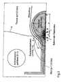
- Figure 2shows a schematic representation of the field line course in an electrode arrangement to explain a Basic idea of the invention.
- the field lines shownshould not show the field strength to scale, but are selected so that certain conditions in the field geometry become clear.
- the blood / tissue distributionis in the schematic representation in the atrium and the adjacent "superior vena cava" shown.
- the myocardiumis also shown of the atrium and the phrenic nerve and the surrounding thorax.
- a third electrode - here the pacemaker housing -is also at potential in the event of stimulation 0 V.
- the floating electrode line(shown in dashed lines) carries electrodes A and B, which are electrical Form dipole, which in the present example Electrode A negative (-1.5 V) and electrode B (+1.5 V) positive compared to the pacemaker housing is poled. It can be seen that in the electrode position shown the potential line of 0 volts (directed almost vertically upwards in the drawing) one Deformation to the third electrode (pacemaker housing) causes.
- Embodimentcarries a conventional (unipolar) ventricular electrode T.
- the distance In the example shown, eis at the center of the distance d between the two electrodes A. and B related.
- the size emay vary, in many cases a maximum of the stimulation effectiveness can already be achieved by suitable positioning can be achieved.
- the distance dis chosen so that an area is maximum Curvature penetrates the stimulation area S. Here, a larger distance is reduced the curvature. If the distance is too small, however, the field area is maximal curved equipotential lines the stimulation area do not reach. To this extent, here, if necessary Attempts to achieve an optimal stimulation effect.
- Another variable in the pictureis the symmetry of the voltage on electrodes A and B.
- By increasing the Potential of the electrode Bcan be the indifferent potential line 0 V also in the area to be stimulated in move.
- this effecthas compared to the geometric sizes have a relatively smaller influence, however, is related to the ratio of stimulation to Myocardial fiber and phrenic nerve matter as below will be detailed.
- the activation function of the mycard fiberis shown in more detail in FIG. 2b). It is - 90 mV.
- a muscle fiberis considered as a component of the myocardium, which extends from the junction the superior vena cava extends into the atrium to the valve level.
- the resting membrane potential and the stimulus thresholdis -90 mV and - 60 mV, respectively. The stimulation the myocardial fiber occurs above threshold.
- the problem with the pacemaker stimulation of the heartis that excitation of the phrenic nerve should be avoided since its stimulation leads to unwanted twitching of the Diaphragm or the pacemaker pocket.
- nerve cellsIn contrast to cardiac muscle cells, nerve cells have a resting membrane potential of about -110 mV.
- the stimulus thresholdis around -90 mV and is therefore subliminal.
- the pacemaker electrode shown hereis simultaneously the "S / N ratio" between desired myocard stimulation and undesired phrenic stimulation optimized. This is achieved through the selected asymmetry of the electrode potentials A and B. Starting from a total voltage of 3 V and the target, the myocardium on the one hand to stimulate as safely as possible and on the other hand to stimulate phrenicus The image shown in FIG. 2b is avoided or minimized as far as possible the potential curves for a pulse voltage of -2.55 V of electrode A and a pulse voltage of + 0.45V of the electrode B. The asymmetry factor in this is (Model) case 1.7 / 0.3. Here rectangular pulses are used, which are phase-synchronous, i.e. synchronous with no offset be delivered.
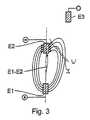
- Fig. 3the electrical field is shown, which is between two with the positive pole "+” or the negative pole "-” electrodes E1 and E2 connected to a voltage source with small dimensions compared to their distance (outdoors Space). It approximately corresponds to the field between two point charges with different signs.
- the potential gradientis on the straight connecting line E1-E2 between the two electrodes E1. E2 largest, and the field strength and thus the potential gradient increases in a first approximation according to Coulomb's law increasing distance from this line.
- the equipotential linesinstead of the equipotential lines here are the deformed electrical field lines shown, always perpendicular to the equipotential lines are directed.
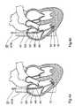
- FIGs 4a and 4bare schematic representations of two with a straight line over the Vena cava superior VCS floating in the right atrium AR of a heart H.
- Electrode lines 10 and 10 'on each of which two Electrodes (sections) 11 and 12 or 11 'and 12' formed are. Both lines are in length and spacing Electrodes 12 and 13 or 12 'and 13' formed and so moved far into the atrium so that in bipolar operation, i.e. when applying a voltage with different Polarity that sine node SA can excite without fixed to the wall or just to be positioned.
- the electrodes shown in both figuresare suitable for two-chamber operation.
- In Figure 4ais a conventional one Ventricular electrode 13 with fixation means at the end the electrode line provided.
- Electrode endis provided, which on its free At the end of the ventricle there is also a floating pair of electrodes 14 and 15. These electrodes are sorted according to geometric principles such as the atrium electrodes dimensioned and are on the endocard of the ventricle directed without being firmly anchored there. In your At the end they have thin tines 16 made of elastic material on which is reset with respect to the electrode end are and do not have the task of the electrode end with the stimulation electrodes in the vicinity of the tissue to fix, but should only serve the Electrode end approximately in the middle cross section of the chamber near its lower end keep centered.
- the inventive effectcan also be achieved with several electrodes can.
- two electrodescan be arranged in the atrium or another electrode located in the superior vena cava.
- the use of one or the other electrode arrangementcan depend on the actual location of the sinus node in a patient and depend on its stimulus threshold.
Landscapes
- Health & Medical Sciences (AREA)
- Heart & Thoracic Surgery (AREA)
- Vascular Medicine (AREA)
- Cardiology (AREA)
- Engineering & Computer Science (AREA)
- Biomedical Technology (AREA)
- Nuclear Medicine, Radiotherapy & Molecular Imaging (AREA)
- Radiology & Medical Imaging (AREA)
- Life Sciences & Earth Sciences (AREA)
- Animal Behavior & Ethology (AREA)
- General Health & Medical Sciences (AREA)
- Public Health (AREA)
- Veterinary Medicine (AREA)
- Electrotherapy Devices (AREA)
Description
Translated fromGermanDie Erfindung betrifft eine Elektrodenanordnung der imOberbegriff des Anspruchs 1 angegebenen Art.The invention relates to an electrode arrangement in thePreamble of claim 1 specified type.
Bei der Therapie verschiedener chronischer Herzrhythmusstörungensind implantierte Herzschrittmacher in Verbindungmit auf einem intrakardialen Elektrodenkatheter angeordnetenund an der Herzinnenwand positionierten Reizelektrodenin Gebrauch, über die das reizbare Herzgewebe erregt wird.Die Ausgestaltung der Schrittmacher und der zugehörigenElektrodenleitungen hat zunehmende Vervollkommnung erfahren,wobei zahlreiche technische Lösungen zur Verankerungder Elektrodenkatheter an der Herzwand - sowohl in derHerzkammer (Ventrikel) als auch im Vorhof (Atrium) - gefundenwurden und tatsächlich wesentliche praktische Verbesserungengelungen sind.In the treatment of various chronic cardiac arrhythmiasimplanted pacemakers are connectedwith arranged on an intracardiac electrode catheterand stimulation electrodes positioned on the inner wall of the heartin use, which excites the irritable heart tissue.The design of the pacemaker and the associatedElectrode leads have seen increasing perfectiontaking numerous technical solutions to anchorthe electrode catheter on the heart wall - both in theVentricle as well as in the atrium - foundwere and actually substantial practical improvementshave succeeded.
Dennoch zählen auch heute noch Elektrodendislokationen, diezu einer Verschlechterung oder gar einem Verlust des Kontaktsmit dem reizbaren Gewebe an der Herzinnenwand und inder Folge zumindest zu einer wesentlichen Erhöhung derReizschwelle und damit einem erhöhten Stromverbrauch desSchrittmachers und einer verringerten Lebensdauer undschlimmstenfalls zu dessen Funktionsunfähigkeit führen, zuden wichtigsten Komplikationen bei der Schrittmachertherapie.Nevertheless, electrode dislocations still count todayworsening or even losing contactwith the irritable tissue on the inner wall of the heart and inconsequently at least to a substantial increase inThreshold and thus an increased power consumption of thePacemaker and a reduced lifespan andat worst, lead to its inability to functionthe main complications of pacemaker therapy.
Weiterhin kann der Umstand, daß bis dato die Reizimpulseeines implantierten Schrittmachers über wandständige Elektrodenan das reizbare Muskelgewebe der Herzinnenwanding imunteren Bereich des Ventrikels bzw. des Atriums übertragenwerden, auch aus grundsätzlichen physiologischen Erwägungenheraus nicht befriedigen.Furthermore, the fact that to date the stimulus impulsesan implanted pacemaker via wall electrodesto the irritable muscle tissue of the inner wall of the heart inlower area of the ventricle or atriumbecome, also for basic physiological considerationsnot satisfy out.
Flottierende Elektroden konnten andererseits bisher nicht mit so großer Sicherheit die Stimulationsicherstellen, dass eine regelmäßige Anwendung vertretbar gewesen wäre.Floating electrodes, on the other hand, have so far not been able to stimulate with such great certaintyensure that regular use would have been acceptable.
Die US 4,825,871 betrifft eine Anordnung zur Behandlung tachyarrythmischer Phänomene.Die Anordnung umfasst eine Elektrodenleitung mit zumindest einer Elektrode, die in dasrechte Atrium des Herzens eingeführt wird. In Abhängigkeit vom Signal eines Herzschlagsensorswird die Abgabe eines Impulses an das Herzgewebe gesteuert.US 4,825,871 relates to an arrangement for treating tachyarrhythmic phenomena.The arrangement comprises an electrode line with at least one electrode, which in theright atrium of the heart is inserted. Depending on the signal from a heartbeat sensorthe delivery of a pulse to the heart tissue is controlled.
In der US 5.172,694 wird eine Elektrodenleitung mit zumindest zwei flotierenden Bipolen imBereich des Atriums des Herzens beschrieben.In US 5,172,694 an electrode line with at least two floating bipoles in theArea of the atrium of the heart described.
Der Erfindung liegt daher die Aufgabe zugrunde, eine verbesserte Elektrodenanordnung dereingangs genannten Gattung anzugeben, die einen hinsichtlich der Reizimpulslokalisierungbesser den physiologischen Gegebenheiten folgenden und zuverlässigeren Betrieb einesHerzschrittmachers ermöglicht.The invention is therefore based on the object of an improved electrode arrangementto specify the genus mentioned at the beginning, one with regard to the localization of stimulus impulsesbetter the more reliable and more reliable operation of aPacemaker enables.
Diese Aufgabe wird durch eine Elektrodenanordnung mit den Merkmalen des Anspruchs 1gelöst.This object is achieved by an electrode arrangement with the features of claim 1solved.
Die Erfindung schließt den Gedanken ein, eine Elektrodenanordnung und -ansteuerung zurealisieren, mit der die Reizimpulse des Schrittmachers den in der Reizbildungshierarchiehochstehenden Bereichen des kardialen Reizbildungs- und -leitungssystems - primär demSinusknoten und sekundär dem AV-Knoten - zugeführt werden können, um etwa ein Sinusknotensyndromdirekt am Entstehungsort zu therapieren oder im Falle eines AV-Blocks eineStimulation unmittelbar an dem vom physiologischen Defekt primär betroffenen Bereich vornehmenzu können.The invention includes the idea of an electrode arrangement and controlrealize with which the stimulus impulses of the pacemaker in the hierarchy of stimulus formationhigh-quality areas of the cardiac stimulus generation and conduction system - primarily thatSinus node and secondary to the AV node - can be supplied to about a sinus node syndrometo be treated directly at the point of origin or in the case of an AV blockApply stimulation directly to the area primarily affected by the physiological defectto be able to.
Zur praktischen Umsetzung dieser Gedanken bedient sich die vorgeschlagene Elektrodenanordnungdes Mittels einer "Fokussierung" des bei gleichzeitiger Abgabe von Reizimpulsesmit entgegengesetzter Polarität in der Umgebung zweier oder mehrerer Elektroden In geeignetergeometrischer Elektrodenanordnung ausgebildeten elektrischen Feldes auf den Sinusknotenbzw. den AV-Knoten oder den sonstigen zu stimulierenden Bereich.The proposed electrode arrangement is used to implement these ideas in practiceby means of a "focusing" of the simultaneous delivery of stimuluswith opposite polarity in the vicinity of two or more electrodesGeometric electrode arrangement formed electrical field on the sinus nodeor the AV node or the other area to be stimulated.
Auf diese Weise ist es möglich, auch bei flottierender Elektrode eine so starke elektrischeReizwirkung lokal zu konzentrieren, dass ein körperlicher Kontakt zwischen Gewebe undReizelektrode nicht erforderlich ist.In this way it is possible to have such a strong electrical even with a floating electrodeFocus irritant that physical contact between tissue andIrritation electrode is not required.
Des weiteren ist für die Erfindung von besonderer Bedeutung, dass das Dipolfeld im Bereichdes Gewebes verzerrt ist. Das Schrittmachergehäuse als indifferente Elektrode bewirkt einestarke Verzerrung des Dipolfeldes. Begünstigt wird dieser Effekt durch die Unstetigkeit desPotentiallinienverlaufs im Übergangsbereich Gewebe Blut wegen des im Blut geringerenspezifischen Widerstands.Furthermore, it is of particular importance for the invention that the dipole field in the areaof the tissue is distorted. The pacemaker housing acts as an indifferent electrodestrong distortion of the dipole field. This effect is favored by the discontinuity of thePotential line course in the transition area tissue blood because of the lower in the bloodspecific resistance.
Die Erhöhung des Potentialgradienten durch die geeignete geometrische Elektrodenanordnungeinerseits und die entgegengesetzte Polarität der Impulse andererseits ermöglicht dieÜberschreitung der Reizschwelle in zu den Elektroden nicht direkt benachbarten Gewebebereichenund damit die Reizung der nicht an der Oberfläche der Herzwand und zudem in Gebietendes Herzens, in denen eine Fixierung von Elektroden praktisch unmöglich ist, liegendenZielbereiche für die Erregung, nämlich des Sinus- bzw. AV-Knotens.The increase in the potential gradient through the appropriate geometric electrode arrangementon the one hand and the opposite polarity of the impulses on the other hand enables theExceeding the stimulation threshold in tissue areas not directly adjacent to the electrodesand thus the irritation not on the surface of the heart wall and also in areasof the heart, in which it is practically impossible to fix electrodesTarget areas for excitation, namely the sinus or AV node.
In einer hinsichtlich der Steuerung des Erregungs-Zielbereiches besonders vorteilhaftenAusgestaltung der Elektrodenanordnung umfaßt diese in räumlicher Beziehung zur erstenund zweiten Elektrode mindestens eine dritte Elektrode, die derart ausgebildet und angeordnetund mit einer vorbestimmten dritten Spannung beaufschlagt ist, dass sie den Potentialgradientenim Bereich des Sinusknotens oder des AV-Knotens über den allein mit der erstenund zweiten Elektrode (bei als vorgegeben vorausgesetzter Spannungsamplitude) erreichbarenWert hinaus erhöht.In a particularly advantageous manner with regard to the control of the excitation target areaDesign of the electrode arrangement includes this in spatial relation to the firstand second electrode at least one third electrode, which is formed and arranged in this wayand a predetermined third voltage is applied to the potential gradientin the area of the sinus node or the AV node over the alone with the firstand second electrode (at a voltage amplitude presupposed as predetermined)Value increased.
In einer in vorteilhafter Weise auf herkömmliche Weise zu konstruierenden und günstig zuimplantierenden Ausführung sind auch die zweite und/oder weitere Elektrode(n) auf der intrakardialverlegten Elektrodenleitung angeordnet.To be constructed in an advantageous manner in a conventional manner and inexpensivelyThe second and / or further electrode (s) on the intracardial are also implantedlaid electrode line.
Diese weist zweckmäßigerweise eine derart bemessene Länge und/oder Krümmung auf,dass die Elektroden nach Einführung in das Herz im Bereich des Atriumdaches nahe derEinmündung der Vena cava superior bzw. nahe des Septums und der Einmündung des Sinuscoronarius in das Atrium , d.h. - je nachdem, ob der Sinusknoten oder der AV-Knotenerregt werden soll - in geringer Entfernung hierzu, angeordnet sind.This expediently has such a length and / or curvature,that the electrodes after insertion into the heart in the area of the atrium roof near theOpening of the superior vena cava or near the septum and the opening of the sinuscoronarius in the atrium, i.e. - depending on whether the sinus node or the AV nodeshould be excited - are arranged at a short distance from this.
Dabei ist in einer bevorzugten Ausgestaltung die Elektrodenleitung derart ausgebildet, daßdie dritte und/oder weitere Elektrode(n) oberhalb der ersten und zweiten Elektrode, insbesondereannähernd auf deren verlängerter gerader Verbindungslinie - für den Fall der Reizungdes Sinusknotens insbesondere in der vena cava superior - angeordnet sind.In a preferred embodiment, the electrode line is designed such thatthe third and / or further electrode (s) above the first and second electrodes, in particularapproximately on their extended straight connecting line - in the event of irritationof the sinus node, especially in the superior vena cava.
Ist hierbei gemäß der oben erwähnten Ausgestaltung eine dritte Elektrode vorgesehen, so istdiese im wesentlichen am Scheitelpunkt der Krümmung der Elektrodenleitung angeordnetderart, dass sie einen Abstand zu einer geraden Verbindungslinie zwischen der ersten undzweiten Elektrode hat.If a third electrode is provided in accordance with the above-mentioned embodiment, thenthese are arranged essentially at the apex of the curvature of the electrode linesuch that they are at a distance from a straight connecting line between the first andsecond electrode.
Da eine Fixierung der Elektrodenleitung an der Herzwand bei der erfindungsgemäßen Elektrodenanordnungnicht erforderlich ist, kann diese im Herzen "schwimmen". Sie wird mithinzweckmäßigerweise mit einer solchen Biegesteifigkeit aufgebaut und gegebenenfalls einersolchen vorgeprägten Krümmung im Längsverlauf versehen, dass die Elektroden nach Einführungin das Herz im wesentlichen nicht in direktem Kontakt mit der Herzwandung stehen,aber nahe dem zu reizenden Bereich angeordnet sind.Since the electrode line is fixed to the heart wall in the electrode arrangement according to the inventionis not required, it can "swim" in the heart. So she willexpediently constructed with such a bending stiffness and optionally oneprovided such a pre-shaped curvature in the longitudinal course that the electrodes after insertionin the heart are essentially not in direct contact with the heart wall,but are located near the area to be stimulated.
In einer bevorzugten Ausführung weist die Elektrodenleitung eine - in einer besonderes variablenAusführung auch nach dem Einführen noch verschiebbare - Verzweigung auf, und diezweite oder eine weitere Elektrode ist auf einem von der Hauptleitung abzweigenden Teil derElektrodenleitung angeordnet, ist, während mindestens zwei Elektroden (darunter die erste)auf der Hauptleitung angeordnet sind.In a preferred embodiment, the electrode line has a - in a particularly variableExecution still movable after insertion - branching on, and thesecond or a further electrode is on a part of the branch branching from the main lineElectrode line is arranged, while at least two electrodes (including the first)are arranged on the main line.
Mit dieser Ausführung ist ein ähnliches Ergebnis erreichbar wie mit dem Vorsehen einerKrümmung und einer dritten Elektrode im Bereich des Scheitelpunktes der Krümmung, nämlicheine Potentialliniendeformation in Richtung auf den Zielbereich hin. Mit Hilfe einerAbzweigung kann diese Verschiebung besser räumlich gesteuert werden als mit einer einsträngigenElektrodenleitung.A result similar to that of providing one can be achieved with this embodimentCurvature and a third electrode in the region of the apex of the curvature, namelya potential line deformation towards the target area. With the help of aThis branch can be controlled spatially better than with a single-legElectrode line.
Die Krümmung bzw. das Abstehen des von der Hauptleitung abzweigendenTeiles der Elektrodenleitung werden durch geeignete(als solche bekannte) Mittel nach der Einführung erzeugt,bevorzugt etwa durch Elemente aus einer bei Körpertemperaturaktivierten Gedächtnislegierung oder Vorspannelementeumfassen, die bei Entfernung eines zum Einführendienenden Führungsdrahtes aus der Elektrodenleitung einevorgeprägte Form annehmen. Es ist auch möglich, Mittel zurVeränderung der Krümmung von außen vorzusehen.The curvature or the protrusion of the branch from the main linePart of the electrode line are made by suitablegenerated means (known as such) after the introduction,preferably about elements from a body temperatureactivated memory alloy or pretensioning elementsinclude that upon removal of one for insertionserving guide wire from the electrode linetake pre-formed shape. It is also possible to use funds forChange in the curvature from the outside.
Eine gegenüber Elektrodenleitungen mit zur Mittelachse symmetrischerElektrodenkonfiguration verbesserte Möglichkeitder Annäherung der Elektroden an den zu beeinflussenden Gewebsbereichbietet eine Ausführung, bei der die Elektrodenbezüglich einer Mittelebene der Elektrodenleitung asymmetrischauf dieser angeordnet sind. Dabei kann ein Teil derElektroden auf einer Seite der Leitung und ein anderer Teilauf der gegenüberliegenden angeordnet sein, es kann aberauch zweckmäßig sein, alle Elektroden auf derselben Seiteder Leitung anzubringen.One with respect to electrode lines with symmetry to the central axisElectrode configuration improved possibilitythe approach of the electrodes to the tissue area to be influencedoffers a version in which the electrodesasymmetrical with respect to a central plane of the electrode lineare arranged on this. Part of theElectrodes on one side of the lead and another partcan be arranged on the opposite, but it canalso be appropriate, all electrodes on the same sideattached to the line.
In einer weiteren bevorzugten Ausführung ist die dritte(oder eine weitere) Elektrode als eine außerhalb des Herzensangeordnete Flächenelektrode, insbesondere als dieSpannungsquelle und die Herzschrittmacher aufnehmendesSchrittmachergehäuse, ausgebildet, wobei diese Flächenelektrodeinsbesondere als indifferente Elektrode geschaltet,d.h. mit Nullpotential verbunden, ist.In a further preferred embodiment, the third(or another) electrode as an outside of the heartarranged surface electrode, in particular as thePower source and pacemaker absorbingPacemaker housing, formed, this surface electrodeswitched in particular as an indifferent electrode,i.e. connected to zero potential.
Die Elektrodenleitung kann bevorzugt mindestens eine Gruppevon vier in axialer Richtung gegeneinander beabstandetenElektrodenabschnitten aufweisen, wobei der erste Spannungsimpulsan den ersten und dritten oder zweiten und vierten Elektrodenabschnitt der Gruppe angelegt wird, sodaß sich ein erstes elektrisches Dipolfeld zwischen diesenAbschnitten aufbaut, und der zweite Impuls an die jeweilsverbleibenden Elektrodenabschnitte der Gruppe angelegtwird, so daß sich ein gegenüber dem ersten Dipolfeld räumlichversetztes zweites Dipolfeld zwischen diesen Elektrodenabschnittenaufbaut.The electrode line can preferably have at least one groupof four spaced apart in the axial directionHave electrode sections, wherein the first voltage pulseto the first and third or second andfourth electrode section of the group is applied, sothat there is a first electric dipole field between themSections builds up, and the second impulse to eachremaining electrode sections of the groupis so that a spatially opposite the first dipole fieldoffset second dipole field between these electrode sectionsbuilds.
Insbersondere sind die Elektroden unterschiedlicher Polaritätderart auf der Elektrodenleitung angeordnet und/oderdas Verhältnis der Potentiale ist derart gewählt, daß diesich einstellenden Äuipotentiallinien (und damit auch dieim wesentlichen die Feldlinien) am Stimulationsort in dieHerzwand ein und aus dieser wieder austreten.In particular, the electrodes are of different polarityso arranged on the electrode line and / orthe ratio of the potentials is chosen such that theemerging potential lines (and thus also theessentially the field lines) at the stimulation site in theHeart wall in and out of this.
Für diese oder ähnliche Ausgestaltungen, bei denen mehrereElektrodengruppen impulsartig anzusteuern sind, sind zweckmäßigerweisezwei (oder mehrere) Impulserzeuger in demHerzschrittmacher vorgesehen, die jeweils im wesentlichenzeitgleich mindestens einen ersten und einen zweiten Spannungsimpulsmit entgegengesetzter Polarität erzeugen können.For these or similar configurations in which severalElectrode groups to be controlled in a pulsed manner are expedienttwo (or more) pulse generators in thePacemakers are provided, each essentiallyat the same time at least a first and a second voltage pulsecan generate with opposite polarity.
Andere vorteilhafte Weiterbildungen der Erfindung sind inden Unteransprüchen gekennzeichnet bzw. werden nachstehendzusammen mit der Beschreibung der bevorzugten Ausführungder Erfindung anhand der Figuren näher dargestellt. Es zeigen:
Die Figuren 2 und 4 fallen nicht unter Anspruch 1, weil die Elektrodenleitungenkeine Verzweigung aufweisen. Diese Figuren sind jedoch nützlich, umeine mögliche elektrische Feldverteilung zu erläutern.Figures 2 and 4 do not fall under claim 1 because the electrode lineshave no branching. However, these figures are useful toexplain a possible electrical field distribution.
Die Lage der Elemente des Reizbildungs- und Erregungsleitungssystemsim Herzen (wozu auch das oben nicht erwähnteHis-Bündel und der - jeweils in die Purkinje-Fasern mündende- linke bzw. rechte Schenkel ("Left" bzw. "Right BundleBranch") gehören - ist zunächst in Fig. 1 skizzenartig gezeigt.The location of the elements of the stimulation and conduction systemin the heart (for which also the above not mentionedHis bundle and the - each ending in the Purkinje fibers- Left or right leg ("Left" or "Right BundleBranch ") belong - is initially shown in sketch form in FIG. 1.
Figur 2 zeigt in schematischer Darstellung den Feldlinienverlaufbei einer Elektrodenanordnung zur Erläuterung einesGrundgedankens der Erfindung. Die dargestellten Feldliniensollen nicht maßstäblich die Feldstärke abbilden, sondernsind so gewählt, daß bestimmte Verhältnisse in der FeldGeometriedeutlich werden.Figure 2 shows a schematic representation of the field line coursein an electrode arrangement to explain aBasic idea of the invention. The field lines shownshould not show the field strength to scale, butare selected so that certain conditions in the field geometrybecome clear.
In der schematischen Darstellung ist die Blut-/Gewebe-Verteilungim Atrium und der angrenzenden "Vena cava superior"dargestellt. Weiterhin wiedergegeben ist der Myokarddes Atriums und der Phrenicus-Nerv und der umgebende Thorax.Eine dritte Elektrode - hier das Schrittmachergehäuse- befindet sich auch im Stimulationsfall auf dem Potential0 V. Die flottierende (gestrichelt dargestellte) Elektrodenleitungträgt die Elektroden A und B, welche einen elektrischenDipol bilden, wobei im vorliegenden Beispiel die Elektrode A negativ (-1,5 V) und die Elektrode B (+1,5 V) positiv gegenüber dem Schrittmachergehäusegepolt ist. Es ist ersichtlich, dass bei der dargestellten Elektrodenpositiondie Potentiallinie von 0 Volt (in der Zeichnung nahezu senkrecht nach oben gerichtet) eineVerformung zur dritten Elektrode (Schrittmachergehäuse) hin bewirkt.The blood / tissue distribution is in the schematic representationin the atrium and the adjacent "superior vena cava"shown. The myocardium is also shownof the atrium and the phrenic nerve and the surrounding thorax.A third electrode - here the pacemaker housing- is also at potential in the event of stimulation0 V. The floating electrode line (shown in dashed lines)carries electrodes A and B, which are electricalForm dipole, which in the present exampleElectrode A negative (-1.5 V) and electrode B (+1.5 V) positive compared to the pacemaker housingis poled. It can be seen that in the electrode position shownthe potential line of 0 volts (directed almost vertically upwards in the drawing) oneDeformation to the third electrode (pacemaker housing) causes.
Die spezifischen Widerstände sind ebenfalls in Figur 2 angegeben. Es ist ferner ersichtlich,dass bei Betrachtung des Schrittmachergehäuses als idealen Leiter (äquipotential bei 0 V)und bei der dargestellten Elektrodenposition sich eine Verzerrung des Dipolfeldes im Bereichdes Myokards ergibt.The specific resistances are also shown in Figure 2. It is also evidentthat when considering the pacemaker case as the ideal conductor (equipotential at 0 V)and with the electrode position shown there is a distortion of the dipole field in the areaof the myocardium.
Dies wird erreicht durch die in Figur 2 wiedergegebene Elektrodengeometrie, welche bestimmtwird durch den Abstand d zwischen den Elektroden und den Abstand e von den Elektrodenbis zum Ende der Elektrode, die in der Herzspitze gelegen ist und beim dargestelltenAusführungsbeispiel eine konventionelle (unipolare) Ventrikelelektrode T trägt. Der Abstande ist im dargestellten Beispiel auf die Mitte des Abstands d der beiden Elektroden Aund B bezogen. Je nach Größe des menschlichen Herzens kann die Größe e variieren,wobei in vielen Fällen bereits durch eine geeignete Positionierung ein Maximum der Stimulationseffektivitäterzielt werden kann. Der Abstand d wird so gewählt, dass ein Bereich maximalerKrümmung den Stimulationsbereich S durchdringt. Hierbei verringert ein größerer Abstanddie Krümmung. Ein zu kleiner Abstand lässt hingegen den Feldbereich maximal gekrümmter Äquipotentiallinien den Stimulationsbereichnicht erreichen. Insoweit kann hier gegebenenfalls durchVersuche ein optimaler Stimulationseffekt erreicht werden.This is achieved by the electrode geometry shown in FIG. 2, which determinesis determined by the distance d between the electrodes and the distance e from the electrodesto the end of the electrode, which is located in the tip of the heart and at the shownEmbodiment carries a conventional (unipolar) ventricular electrode T. The distanceIn the example shown, e is at the center of the distance d between the two electrodes A.and B related. Depending on the size of the human heart, the size e may vary,in many cases a maximum of the stimulation effectiveness can already be achieved by suitable positioningcan be achieved. The distance d is chosen so that an area is maximumCurvature penetrates the stimulation area S. Here, a larger distance is reducedthe curvature. If the distance is too small, however, the field area is maximalcurved equipotential lines the stimulation areado not reach. To this extent, here, if necessaryAttempts to achieve an optimal stimulation effect.
Eine weitere Variable im Bild ist die Symmetrie der Spannungan den Elektroden A und B. Durch eine Vergrößerung desPotentials der Elektrode B läßt sich die indifferente Potentiallinie0 V ebenfalls in den zu stimulierenden Bereichin verschieben. Dieser Effekt hat jedoch im Vergleich zuden geometrischen Größen einen relativ geringeren Einfluß,ist jedoch in Bezug auf das Verhältnis der Stimulation vonMyocardfaser und Phrenicus von Bedeutung, wie weiter untennäher ausgeführt werden wird.Another variable in the picture is the symmetry of the voltageon electrodes A and B. By increasing thePotential of the electrode B can be the indifferent potential line0 V also in the area to be stimulatedin move. However, this effect has compared tothe geometric sizes have a relatively smaller influence,however, is related to the ratio of stimulation toMyocardial fiber and phrenic nerve matter as belowwill be detailed.
Mit der im Bild schematisch dargestellten Elektrodengeometrieläßt sich die beschriebene Potentialverteilung im Eingangsbereichder Vena Cava Superior zum Atrium hin gut erreichen.In Figur 2 ist ersichtlich, daß im Bereich S dieKrümmung der Äquipotentiallininen so groß ist, daß auch diesenkrecht dazu verlaufenden Feldlinien im Stimulationsbereichin die Herzwand ein und wieder austreten. Damitzeichnet sich der Stimulationsbereich durch eine Zone aus,in der die erzeugten Feldstärken ein Maximum sind.With the electrode geometry shown schematically in the picturethe described potential distribution in the entrance areaReach the Vena Cava Superior towards the atrium.In Figure 2 it can be seen that in area S theThe curvature of the equipotential lines is so large that theField lines running perpendicular to it in the stimulation areaenter and exit the heart wall. In order tothe stimulation area is characterized by a zone,in which the generated field strengths are a maximum.
In den Figuren 2a bis d ist der Einfluß dargestellt, dersich durch die Impulssymmetrie auf die Stimulation vonHerzmuskelzellen und Phrenicus ergibt. In Figur 2a in einervereinfachten Modellgeometrie der relative Verlauf vonPhrenicus und Myokard wiedergegeben. Der Phrenicus ist alsdurchgehenden Nervenstrang aufzufassen und seine Erregbarkeithat einen charakteristischen Verlauf, der weiter untennäher dargestellt ist.In Figures 2a to d the influence is shownby the impulse symmetry on the stimulation ofCardiac muscle cells and phrenic nerve results. In Figure 2a in onesimplified model geometry the relative course ofPhrenic nerve and myocardium reproduced. The phrenic nerve is calledcontinuous nerve cord and his excitabilityhas a characteristic course that belowis shown in more detail.
Die Aktivierungsfunktion der Mycardfaser ist in Figur 2b) näher dargestellt. Sie liegt bei -90 mV. Als Myocardbestandteil wird eine Muskelfaser betrachtet, die sich von der Einmündungder vena cava superior ins Atrium hinein bis zur Ventilebene erstreckt. Das Ruhemembranpotentialund die Reizschwelle liegen bei -90 mV bzw. bei - 60 mV. Die Stimulationder Myocardfaser erfolgt überschwellig.The activation function of the mycard fiber is shown in more detail in FIG. 2b). It is -90 mV. A muscle fiber is considered as a component of the myocardium, which extends from the junctionthe superior vena cava extends into the atrium to the valve level. The resting membrane potentialand the stimulus threshold is -90 mV and - 60 mV, respectively. The stimulationthe myocardial fiber occurs above threshold.
Es stellt sich bei der Schrittmacherstimulation des Herzens das Problem, dass eine Erregungdes Phrenicus vermieden werden soll, da seine Stimulation zu unerwünschtem Zucken desDiaphragmas oder der Schrittmachertasche führt.The problem with the pacemaker stimulation of the heart is that excitationof the phrenic nerve should be avoided since its stimulation leads to unwanted twitching of theDiaphragm or the pacemaker pocket.
Im Gegensatz zu Herzmuskelzellen haben Nervenzellen ein Ruhemembranpotential vonetwa -110 mV. Die Reizschwelle liegt um -90 mV und ist damit unterschwellig.In contrast to cardiac muscle cells, nerve cells have a resting membrane potential ofabout -110 mV. The stimulus threshold is around -90 mV and is therefore subliminal.
Um dafür Sorge zu tragen, dass die Myocardfasem oberschwellig, die Nervenzellen abernicht stimuliert werden, wird bei der hier dargestellten Schrittmacherelektrode gleichzeitig der"Störabstand" zwischen gewünschter Myocardstimulation und unerwünschter Phrenicusstimulationoptimiert. Dies wird erreicht durch die gewählte Unssymmetrie der ElektrodenpotentialeA und B. Ausgehend von einer Gesamtspannung von 3 V und dem Ziel, das Myokardeinerseits möglichst sicher zu stimulieren und andererseits gleichzeitig die Phrenicusstimulationmöglichst zu vermeiden bzw. zu minimieren ergibt sich das in Fig. 2b dargestellte Bildder Potentialverläufe für eine Impulsspannung von -2,55 V der Elektrode A und einer Impulsspannungvon + 0,45V der Elektrode B. Der Unsymmetriefaktor beträgt in diesem(Modell-) Fall 1,7/0,3. Hierbei werden Rechteckimpulse zugrundegelegt, welche konphasisch, also zeitsynchron ohne Versatzabgegeben werden.To ensure that the myocardial fibers are above threshold, but the nerve cellsare not stimulated, the pacemaker electrode shown here is simultaneously the"S / N ratio" between desired myocard stimulation and undesired phrenic stimulationoptimized. This is achieved through the selected asymmetry of the electrode potentialsA and B. Starting from a total voltage of 3 V and the target, the myocardiumon the one hand to stimulate as safely as possible and on the other hand to stimulate phrenicusThe image shown in FIG. 2b is avoided or minimized as far as possiblethe potential curves for a pulse voltage of -2.55 V of electrode A and a pulse voltageof + 0.45V of the electrode B. The asymmetry factor in this is(Model) case 1.7 / 0.3. Here rectangular pulses are used,which are phase-synchronous, i.e. synchronous with no offsetbe delivered.
Dieses Optimum ist von Patient zu Patient unterschiedlichund kann durch individuelle Programmierung erfolgen, nachdemdie Elektrode im Herzen verlegt ist. Hierbei ist zu berücksichtigen,daß Myokard und Phrenicus nicht in einerEbene gelegen sind. Der sich tatsächlich einstellendeStörabstand ist also weitaus besser als der hier an einemzweidimensionalen Modell errechnete theoretische Wert. Esist zu berücksichtigen, daß gemäß der Erfindung eine Fokussierungzunächst auf die Myocard-Stimulation erfolgen muß.Durch eine Veränderung der Symmetrie der Impulse kann dannnachträglich versucht werden, eine eventuell zu bemerkendestörende Stimulation des Phrenicus durch Umprogrammierungder Symmetrie und somit "Ausblenden" zu beseitigen.This optimum varies from patient to patientand can be done by custom programming afterthe electrode is in the heart. It should be taken into accountthat myocardium and phrenic nerve are not in oneLevel. The one that actually sets inSo the signal-to-noise ratio is far better than the one heretwo-dimensional model calculated theoretical value. Itit should be borne in mind that according to the invention focusingmust first be done on the myocard stimulation.By changing the symmetry of the impulses can thensubsequently tried to find a possibly noticeabledisturbing stimulation of the phrenic nerve by reprogrammingthe symmetry and thus to "hide".
In Fig. 3 ist das elektrische Feld gezeigt, das sich zwischenzwei mit dem positiven Pol "+" bzw. dem negativen Pol"-" einer Spannungsquelle verbundenen Elektroden E1 und E2mit gegenüber ihrem Abstand kleinen Abmessungen (im freienRaum) ausbildet. Es entspricht näherungsweise dem Feld zwischenzwei Punktladungen mit unterschiedlichem Vorzeichen.Der Potentialgradient ist auf der geraden VerbindungslinieE1-E2 zwischen den beiden Elektroden E1. E2 am größten, unddie Feldstärke und damit auch der Potentialgradient nimmtin erster Näherung entsprechend dem Coulombschen Gesetz mitwachsendem Abstand von dieser Linie ab. Anstelle der Äquipotentialliniensind hier die verformten elektrischen Feldliniendargestellt, stets senkrecht zu den Äquipotentialliniengerichtet sind.In Fig. 3 the electrical field is shown, which is betweentwo with the positive pole "+" or the negative pole"-" electrodes E1 and E2 connected to a voltage sourcewith small dimensions compared to their distance (outdoorsSpace). It approximately corresponds to the field betweentwo point charges with different signs.The potential gradient is on the straight connecting lineE1-E2 between the two electrodes E1. E2 largest, andthe field strength and thus the potential gradient increasesin a first approximation according to Coulomb's lawincreasing distance from this line. Instead of the equipotential lineshere are the deformed electrical field linesshown, always perpendicular to the equipotential linesare directed.
Wie ersichtlich ist, tritt ein ähnlicher, aber hinsichtlichder Verbindungslinie E1-E2 zwischen der ersten und zweitenElektrode E1, E2 asymmetrischer, Effekt bei Plazierung einerdritten Elektrode E3" mit einem Abstand von der verlängertenVerbindungslinie E1-E2 auf. Im der dritten Elektrodeabgewandten Halbraum hat sich - wiederum gleiche Spannungenwie bei den übrigen Figuren vorausgesetzt - der Wirkungsbereichdes Feldes verkleinert, in dem ihr zugewandten Halbraumhat er sich ausgeweitet. Es ist ersichtlich, daß indem Bereich der Elektrode E2, die der Elektrode E3 zugewandtist, eine starke Verzerrung der Feldlinien - in Richtungauf E3 zu - erfolgt ist. Folgt die Herzwand einem inFigur 3 dargestellten und mit W bezeichneten gestricheltenVerlauf, so treten die Feldlinien im Stimulationsbereich Sin diese Herzwand ein und auch wieder daraus hervor.As can be seen, a similar occurs, but in terms ofthe connecting line E1-E2 between the first and secondElectrode E1, E2 asymmetrical, effect when placing onethird electrode E3 "at a distance from the extended oneConnection line E1-E2. In the third electrodehalf space turned away - again equal tensionsas assumed for the other figures - the area of effectof the field in the half space facing herhe has expanded. It can be seen that inthe area of the electrode E2 facing the electrode E3is, a strong distortion of the field lines - towardstowards E3. Does the heart wall follow you inFigure 3 shown and denoted by W dashedThe field lines occur in the stimulation area Sinto and out of this wall of the heart.
Ähnliche, für den Fachmann aufgrund der Gesetze der Elektrostatikberechenbare Effekte treten bei veränderten Elektrodenpolaritätenund räumlichen Elektrodenanordnungen auf,wobei die konkreten Feldlinienbilder natürlich auch von denBeträgen der angelegten Spannungen abhängen.Similar, for the specialist due to the laws of electrostaticsPredictable effects occur with changed electrode polaritiesand spatial electrode arrangements,the concrete field line pictures of course also from theDepend on the amounts of the applied voltages.
Die oben skizzierten und erläuterten Verhältnisse gelten -wie Untersuchungen bestätigt haben - näherungsweise auchfür (als solche bekannte) Elektrodenleitungen bzw. -katheter mit einer isolierenden Umhüllung und mehreren voneinanderbeabstandeten und isolierten Elektrodenabschnittenund insbesondere auch für Elektrodenanordnungen in einerphysiologischen Flüssigkeit.The conditions outlined and explained above apply -as studies have confirmed - approximately alsofor (known as such) electrode lines or -catheter with an insulating sheath and several from each otherspaced and insulated electrode sectionsand in particular also for electrode arrangements in onephysiological fluid.
Aufgrund der Möglichkeit, Elektrodenkatheter im Herzen imwesentlichen geradlinig flottierend zu verlegen, kann eineVielzahl von Konfigurationen angegeben werden, mit denen die Erfindung realisiert und über ein in ihrer Umgebung erzeugtes,hinreichend starkes elektrisches Feld direkt derSinus- oder der AV-Knoten erregt wird.Because of the ability to have cathode electrodes in the heartto lay essentially linearly floating, can beVariety of configurations can be specified with whichrealizes the invention and uses asufficiently strong electric field directly theSinus or the AV node is excited.
Nachfolgend werden hierfür Beispiele angegeben, die jedochnicht im Sinne einer Beschränkung zu verstehen sind.Examples are given below, howeverare not to be understood as a limitation.
Die Figuren 4a und 4b sind schematische Darstellungen zweiermit geradlinigem Verlauf über die Vena cava superior VCSschwimmend in das rechte Atrium AR eines Herzens H verlegteElektrodenleitungen 10 bzw. 10', auf denen jeweils zweiElektroden(abschnitte) 11 und 12 bzw. 11' und 12' gebildetsind. Beide Leitungen sind in der Länge und im Abstand derElektroden 12 und 13 bzw. 12' und 13' so ausgebildet und soweit in das Atrium hinein verlegt, daß sie im bipolaren Betrieb,d.h. bei Anlegen einer Spannung mit unterschiedlicherPolarität, den Sinusknoten SA erregen können, ohnewandständig fixiert oder auch nur positioniert sein zu müssen.Die in beiden Figuren dargestellten Elektroden sindfür Zweikammerbetrieb geeignet. In Figur 4a ist eine herkömmlicheVentrikelelektrode 13 mit Fixationsmitteln am Endeder Elektrodenleitung vorgesehen. In Figur 4b ist einesentsprechende Elektrode vorgesehen, welche an ihrem freienEnde im Ventrikel ein ebenfalls flottierendes Elektrodenpaar14 und 15 aufweist. Diese Elektroden werden nach entsprechendengeometrischen Grundsätzen wie die Atriumelektrodendimensioniert und sind auf das Endocard des Ventrikelsgerichtet, ohne dort fest verankert zu sein. In ihremEndbereich weisen sie dünne Tines 16 aus elastischem Materialauf, welche in Bezug auf das Elektrodenende zurückgesetztsind und nicht die Aufgabe haben, das Elektrodenendemit den Stimulationselektroden in der Nachbarschaft des Gewebeszu Fixieren, sondern sollen nur dazu dienen, das Elektrodenende etwa im mittleren Querschnitt der Kammer in der Nähe ihres unteren Endeszentriert zu halten.Figures 4a and 4b are schematic representations of twowith a straight line over the Vena cava superior VCSfloating in the right atrium AR of a heart H.Electrode lines 10 and 10 ', on each of which twoElectrodes (sections) 11 and 12 or 11 'and 12' formedare. Both lines are in length and
Es ist ersichtlich, da der erfinderische Effekt auch mit mehreren Elektroden erreicht werdenkann. So können zwei Elektroden im Atrium angeordnet oder aber auch eine weitere Elektrodein der Vena cava superior gelegen sein. Der Einsatz der einen oder der anderen Elektrodenanordnungkann von der tatsächlichen Lage des Sinusknotens bei einem Patientenund von dessen Reizschwelle abhängen.It can be seen that the inventive effect can also be achieved with several electrodescan. For example, two electrodes can be arranged in the atrium or another electrodelocated in the superior vena cava. The use of one or the other electrode arrangementcan depend on the actual location of the sinus node in a patientand depend on its stimulus threshold.
Claims (8)
- An electrode arrangement for stimulating the heart by means ofan implantable cardiac pacemaker for generating electrical pulses,comprising at least a first electrode (E1) which can be connected to a firstoutput of the cardiac pacemaker and which is arranged on an electrode linewhich can be fitted intracardially and which is not attached to the wall, anda second electrode (E2) for transmitting the electrical stimulation pulses tothe excitable heart tissue, which second electrode is spaced from the firstelectrode and can be connected to a second output of the cardiacpacemaker,
characterised in that
the electrode line has a main line and a branching, wherein the firstelectrode and at least one further electrode are arranged on the main lineand the second or a further electrode is arranged on the branching. - An electrode arrangement according to claim 1characterised inthat the branching of the electrode line is displaceable after insertion.
- An electrode arrangement according to one of the precedingclaimscharacterised in that the electrodes have a fractal surface.
- An electrode arrangement according to one of the precedingclaimscharacterised in that the polarity ratio is adjustable and in particularprogrammable by fine adjusting means.
- An electrode arrangement according to one of the precedingclaimscharacterised in that in the case of a dual-chamber electrodeprovided in the atrium and in the ventricle are first and second respectiveelectrodes (11', 12', 14, 15) which are of a floating nature.
- An electrode arrangement according to claim 5characterised inthat the end of the electrode line (10'), which is intended for stimulation inthe ventricle, has spacing means (16) which hold the first and secondelectrodes (14, 15) intended for stimulation in the ventricle in centredrelationship in the region of the tip of the heart.
- An electrode arrangement according to one of the precedingclaimscharacterised in that the further electrode (E3) is in the form of asurface electrode arranged outside the heart, in particular in the form ofthe housing of the cardiac pacemaker.
- An electrode arrangement according to claim 7characterised inthat the surface electrode (E3) is connected as an indifferent electrode.
Applications Claiming Priority (3)
| Application Number | Priority Date | Filing Date | Title |
|---|---|---|---|
| DE19609471 | 1996-03-01 | ||
| DE19609471ADE19609471A1 (en) | 1996-03-01 | 1996-03-01 | Electrode arrangement |
| PCT/DE1997/000520WO1997031678A1 (en) | 1996-03-01 | 1997-03-03 | Electrode arrangement |
Publications (2)
| Publication Number | Publication Date |
|---|---|
| EP0892653A1 EP0892653A1 (en) | 1999-01-27 |
| EP0892653B1true EP0892653B1 (en) | 2003-07-02 |
Family
ID=7787918
Family Applications (1)
| Application Number | Title | Priority Date | Filing Date |
|---|---|---|---|
| EP97919275AExpired - LifetimeEP0892653B1 (en) | 1996-03-01 | 1997-03-03 | Electrode arrangement |
Country Status (5)
| Country | Link |
|---|---|
| US (1) | US6230061B1 (en) |
| EP (1) | EP0892653B1 (en) |
| AU (1) | AU2380297A (en) |
| DE (2) | DE19609471A1 (en) |
| WO (1) | WO1997031678A1 (en) |
Cited By (5)
| Publication number | Priority date | Publication date | Assignee | Title |
|---|---|---|---|---|
| US7082336B2 (en) | 2003-06-04 | 2006-07-25 | Synecor, Llc | Implantable intravascular device for defibrillation and/or pacing |
| US7529589B2 (en) | 2003-06-04 | 2009-05-05 | Synecor Llc | Intravascular electrophysiological system and methods |
| US7617007B2 (en) | 2003-06-04 | 2009-11-10 | Synecor Llc | Method and apparatus for retaining medical implants within body vessels |
| US7747335B2 (en) | 2003-12-12 | 2010-06-29 | Synecor Llc | Implantable medical device having pre-implant exoskeleton |
| US8239045B2 (en) | 2003-06-04 | 2012-08-07 | Synecor Llc | Device and method for retaining a medical device within a vessel |
Families Citing this family (65)
| Publication number | Priority date | Publication date | Assignee | Title |
|---|---|---|---|---|
| DE19654491A1 (en) | 1996-12-17 | 1998-06-18 | Biotronik Mess & Therapieg | Stimulation electrode arrangement |
| US6907295B2 (en) | 2001-08-31 | 2005-06-14 | Biocontrol Medical Ltd. | Electrode assembly for nerve control |
| US6892098B2 (en) | 2001-04-26 | 2005-05-10 | Biocontrol Medical Ltd. | Nerve stimulation for treating spasticity, tremor, muscle weakness, and other motor disorders |
| US7778703B2 (en)* | 2001-08-31 | 2010-08-17 | Bio Control Medical (B.C.M.) Ltd. | Selective nerve fiber stimulation for treating heart conditions |
| US8615294B2 (en)* | 2008-08-13 | 2013-12-24 | Bio Control Medical (B.C.M.) Ltd. | Electrode devices for nerve stimulation and cardiac sensing |
| US7778711B2 (en)* | 2001-08-31 | 2010-08-17 | Bio Control Medical (B.C.M.) Ltd. | Reduction of heart rate variability by parasympathetic stimulation |
| US7734355B2 (en) | 2001-08-31 | 2010-06-08 | Bio Control Medical (B.C.M.) Ltd. | Treatment of disorders by unidirectional nerve stimulation |
| US7904176B2 (en)* | 2006-09-07 | 2011-03-08 | Bio Control Medical (B.C.M.) Ltd. | Techniques for reducing pain associated with nerve stimulation |
| US7885709B2 (en)* | 2001-08-31 | 2011-02-08 | Bio Control Medical (B.C.M.) Ltd. | Nerve stimulation for treating disorders |
| US8571653B2 (en)* | 2001-08-31 | 2013-10-29 | Bio Control Medical (B.C.M.) Ltd. | Nerve stimulation techniques |
| US7974693B2 (en) | 2001-08-31 | 2011-07-05 | Bio Control Medical (B.C.M.) Ltd. | Techniques for applying, configuring, and coordinating nerve fiber stimulation |
| US8565896B2 (en) | 2010-11-22 | 2013-10-22 | Bio Control Medical (B.C.M.) Ltd. | Electrode cuff with recesses |
| US6772008B2 (en)* | 2001-09-28 | 2004-08-03 | Cardiac Pacemakers, Inc. | Method and apparatus for avoidance of phrenic nerve stimulation during cardiac pacing |
| US6974533B2 (en)* | 2002-04-11 | 2005-12-13 | Second Sight Medical Products, Inc. | Platinum electrode and method for manufacturing the same |
| US7887681B2 (en)* | 2002-04-11 | 2011-02-15 | Second Sight Medical Products, Inc. | Platinum electrode surface coating and method for manufacturing the same |
| US8389434B2 (en)* | 2002-04-11 | 2013-03-05 | Second Sight Medical Products, Inc. | Catalyst and a method for manufacturing the same |
| US7844346B2 (en) | 2002-05-23 | 2010-11-30 | Biocontrol Medical Ltd. | Electrode assembly for nerve control |
| US8204591B2 (en)* | 2002-05-23 | 2012-06-19 | Bio Control Medical (B.C.M.) Ltd. | Techniques for prevention of atrial fibrillation |
| US7321793B2 (en) | 2003-06-13 | 2008-01-22 | Biocontrol Medical Ltd. | Vagal stimulation for atrial fibrillation therapy |
| US7885711B2 (en)* | 2003-06-13 | 2011-02-08 | Bio Control Medical (B.C.M.) Ltd. | Vagal stimulation for anti-embolic therapy |
| US7561922B2 (en)* | 2004-12-22 | 2009-07-14 | Biocontrol Medical Ltd. | Construction of electrode assembly for nerve control |
| US7627384B2 (en)* | 2004-11-15 | 2009-12-01 | Bio Control Medical (B.C.M.) Ltd. | Techniques for nerve stimulation |
| US8880192B2 (en) | 2012-04-02 | 2014-11-04 | Bio Control Medical (B.C.M.) Ltd. | Electrode cuffs |
| US7571011B2 (en)* | 2003-05-01 | 2009-08-04 | Second Sight Medical Products, Inc. | Adherent metal oxide coating forming a high surface area electrode |
| US8060197B2 (en)* | 2003-05-23 | 2011-11-15 | Bio Control Medical (B.C.M.) Ltd. | Parasympathetic stimulation for termination of non-sinus atrial tachycardia |
| US8718791B2 (en) | 2003-05-23 | 2014-05-06 | Bio Control Medical (B.C.M.) Ltd. | Electrode cuffs |
| US20100010603A1 (en) | 2008-07-09 | 2010-01-14 | Tamir Ben-David | Electrode cuffs |
| WO2004110549A2 (en)* | 2003-06-13 | 2004-12-23 | Biocontrol Medical Ltd. | Applications of vagal stimulation |
| DE10331106A1 (en) | 2003-07-04 | 2005-01-27 | Biotronik Meß- und Therapiegeräte GmbH & Co. Ingenieurbüro Berlin | electrode line |
| AU2005212341B2 (en)* | 2004-02-10 | 2011-11-24 | Synecor, Llc. | Intravascular delivery system for therapeutic agents |
| PL1759536T3 (en)* | 2004-06-01 | 2011-10-31 | Kwalata Trading Ltd | In vitro techniques for use with stem cells |
| US8116881B2 (en) | 2004-06-10 | 2012-02-14 | Bio Control Medical (B.C.M.) Ltd | Electrode assembly for nerve control |
| US20060110374A1 (en)* | 2004-11-24 | 2006-05-25 | Dudy Czeiger | Method to accelerate stem cell recruitment and homing |
| US8050756B2 (en) | 2004-12-20 | 2011-11-01 | Cardiac Pacemakers, Inc. | Circuit-based devices and methods for pulse control of endocardial pacing in cardiac rhythm management |
| AR047851A1 (en) | 2004-12-20 | 2006-03-01 | Giniger Alberto German | A NEW MARCAPASOS THAT RESTORES OR PRESERVES THE PHYSIOLOGICAL ELECTRIC DRIVING OF THE HEART AND A METHOD OF APPLICATION |
| US8010191B2 (en) | 2004-12-20 | 2011-08-30 | Cardiac Pacemakers, Inc. | Systems, devices and methods for monitoring efficiency of pacing |
| US8326423B2 (en) | 2004-12-20 | 2012-12-04 | Cardiac Pacemakers, Inc. | Devices and methods for steering electrical stimulation in cardiac rhythm management |
| US8290586B2 (en)* | 2004-12-20 | 2012-10-16 | Cardiac Pacemakers, Inc. | Methods, devices and systems for single-chamber pacing using a dual-chamber pacing device |
| US8005544B2 (en) | 2004-12-20 | 2011-08-23 | Cardiac Pacemakers, Inc. | Endocardial pacing devices and methods useful for resynchronization and defibrillation |
| US8014861B2 (en)* | 2004-12-20 | 2011-09-06 | Cardiac Pacemakers, Inc. | Systems, devices and methods relating to endocardial pacing for resynchronization |
| US8010192B2 (en)* | 2004-12-20 | 2011-08-30 | Cardiac Pacemakers, Inc. | Endocardial pacing relating to conduction abnormalities |
| US8423139B2 (en) | 2004-12-20 | 2013-04-16 | Cardiac Pacemakers, Inc. | Methods, devices and systems for cardiac rhythm management using an electrode arrangement |
| US8609082B2 (en) | 2005-01-25 | 2013-12-17 | Bio Control Medical Ltd. | Administering bone marrow progenitor cells or myoblasts followed by application of an electrical current for cardiac repair, increasing blood supply or enhancing angiogenesis |
| US20070089992A1 (en)* | 2005-10-26 | 2007-04-26 | Dao Zhou | Electrode surface coating and method for manufacturing the same |
| TW200734462A (en) | 2006-03-08 | 2007-09-16 | In Motion Invest Ltd | Regulating stem cells |
| US20070258437A1 (en)* | 2006-05-05 | 2007-11-08 | Broadcom Corporation, A California Corporation | Switching network employing server quarantine functionality |
| WO2010071849A2 (en)* | 2008-12-19 | 2010-06-24 | Action Medical, Inc. | Devices, methods, and systems including cardiac pacing |
| WO2011139691A1 (en) | 2010-04-27 | 2011-11-10 | Cardiac Pacemakers, Inc. | His-bundle capture verification and monitoring |
| US8788045B2 (en) | 2010-06-08 | 2014-07-22 | Bluewind Medical Ltd. | Tibial nerve stimulation |
| US9186504B2 (en) | 2010-11-15 | 2015-11-17 | Rainbow Medical Ltd | Sleep apnea treatment |
| US9457186B2 (en) | 2010-11-15 | 2016-10-04 | Bluewind Medical Ltd. | Bilateral feedback |
| WO2013111137A2 (en) | 2012-01-26 | 2013-08-01 | Rainbow Medical Ltd. | Wireless neurqstimulatqrs |
| WO2014087337A1 (en) | 2012-12-06 | 2014-06-12 | Bluewind Medical Ltd. | Delivery of implantable neurostimulators |
| US9370660B2 (en) | 2013-03-29 | 2016-06-21 | Rainbow Medical Ltd. | Independently-controlled bidirectional nerve stimulation |
| US9604065B2 (en) | 2013-08-30 | 2017-03-28 | Cardiac Pacemakers, Inc. | Unwanted stimulation detection during cardiac pacing |
| US9533159B2 (en) | 2013-08-30 | 2017-01-03 | Cardiac Pacemakers, Inc. | Unwanted stimulation detection during cardiac pacing |
| US9597521B2 (en) | 2015-01-21 | 2017-03-21 | Bluewind Medical Ltd. | Transmitting coils for neurostimulation |
| US9764146B2 (en) | 2015-01-21 | 2017-09-19 | Bluewind Medical Ltd. | Extracorporeal implant controllers |
| US10004896B2 (en) | 2015-01-21 | 2018-06-26 | Bluewind Medical Ltd. | Anchors and implant devices |
| US9782589B2 (en) | 2015-06-10 | 2017-10-10 | Bluewind Medical Ltd. | Implantable electrostimulator for improving blood flow |
| US10105540B2 (en) | 2015-11-09 | 2018-10-23 | Bluewind Medical Ltd. | Optimization of application of current |
| US9713707B2 (en) | 2015-11-12 | 2017-07-25 | Bluewind Medical Ltd. | Inhibition of implant migration |
| US10124178B2 (en) | 2016-11-23 | 2018-11-13 | Bluewind Medical Ltd. | Implant and delivery tool therefor |
| US20180353764A1 (en) | 2017-06-13 | 2018-12-13 | Bluewind Medical Ltd. | Antenna configuration |
| US11400299B1 (en) | 2021-09-14 | 2022-08-02 | Rainbow Medical Ltd. | Flexible antenna for stimulator |
Citations (2)
| Publication number | Priority date | Publication date | Assignee | Title |
|---|---|---|---|---|
| US4825871A (en)* | 1984-03-27 | 1989-05-02 | Societe Anonyme Dite: Atesys | Defibrillating or cardioverting electric shock system including electrodes |
| EP0601338A1 (en)* | 1992-12-11 | 1994-06-15 | Pacesetter AB | Electrode system for a defibrillator |
Family Cites Families (4)
| Publication number | Priority date | Publication date | Assignee | Title |
|---|---|---|---|---|
| GB1424355A (en) | 1972-03-11 | 1976-02-11 | Kent Cambridge Medical Ltd | Cardiac pacers |
| US5172694A (en)* | 1991-05-30 | 1992-12-22 | Vitatron Medical B.V. | Single pacing lead and method utilizing two different floating bipoles |
| US5376103A (en)* | 1992-03-19 | 1994-12-27 | Angeion Corporation | Electrode system for implantable defibrillator |
| SE9401267D0 (en)* | 1994-04-14 | 1994-04-14 | Siemens Elema Ab | The electrode device |
- 1996
- 1996-03-01DEDE19609471Apatent/DE19609471A1/ennot_activeCeased
- 1997
- 1997-03-03AUAU23802/97Apatent/AU2380297A/ennot_activeAbandoned
- 1997-03-03DEDE59710379Tpatent/DE59710379D1/ennot_activeExpired - Lifetime
- 1997-03-03WOPCT/DE1997/000520patent/WO1997031678A1/enactiveIP Right Grant
- 1997-03-03USUS09/142,085patent/US6230061B1/ennot_activeExpired - Lifetime
- 1997-03-03EPEP97919275Apatent/EP0892653B1/ennot_activeExpired - Lifetime
Patent Citations (2)
| Publication number | Priority date | Publication date | Assignee | Title |
|---|---|---|---|---|
| US4825871A (en)* | 1984-03-27 | 1989-05-02 | Societe Anonyme Dite: Atesys | Defibrillating or cardioverting electric shock system including electrodes |
| EP0601338A1 (en)* | 1992-12-11 | 1994-06-15 | Pacesetter AB | Electrode system for a defibrillator |
Cited By (8)
| Publication number | Priority date | Publication date | Assignee | Title |
|---|---|---|---|---|
| US7082336B2 (en) | 2003-06-04 | 2006-07-25 | Synecor, Llc | Implantable intravascular device for defibrillation and/or pacing |
| US7529589B2 (en) | 2003-06-04 | 2009-05-05 | Synecor Llc | Intravascular electrophysiological system and methods |
| US7617007B2 (en) | 2003-06-04 | 2009-11-10 | Synecor Llc | Method and apparatus for retaining medical implants within body vessels |
| US7734343B2 (en) | 2003-06-04 | 2010-06-08 | Synecor, Llc | Implantable intravascular device for defibrillation and/or pacing |
| US7840282B2 (en) | 2003-06-04 | 2010-11-23 | Synecor Llc | Method and apparatus for retaining medical implants within body vessels |
| US7899554B2 (en) | 2003-06-04 | 2011-03-01 | Synecor Llc | Intravascular System and Method |
| US8239045B2 (en) | 2003-06-04 | 2012-08-07 | Synecor Llc | Device and method for retaining a medical device within a vessel |
| US7747335B2 (en) | 2003-12-12 | 2010-06-29 | Synecor Llc | Implantable medical device having pre-implant exoskeleton |
Also Published As
| Publication number | Publication date |
|---|---|
| DE19609471A1 (en) | 1997-11-13 |
| US6230061B1 (en) | 2001-05-08 |
| WO1997031678A1 (en) | 1997-09-04 |
| EP0892653A1 (en) | 1999-01-27 |
| DE59710379D1 (en) | 2003-08-07 |
| AU2380297A (en) | 1997-09-16 |
Similar Documents
| Publication | Publication Date | Title |
|---|---|---|
| EP0892653B1 (en) | Electrode arrangement | |
| DE69321690T2 (en) | Electrode system for a defibrillation device | |
| EP1364678B1 (en) | Lead system | |
| DE69429634T2 (en) | Sequential Cardiac Irritation (DDD) catheter with a single lead inserted through the coronary sinus | |
| DE69837481T2 (en) | DEVICE FOR ADJUSTING THE STIMULATION LOCATION OF ELECTRICALLY IRRITABLE TISSUE | |
| DE69514126T2 (en) | Electrode permanently implanted by sewing to elute medication | |
| DE69503467T2 (en) | TEMPORARY MEDICAL ELECTRODE | |
| DE69329013T2 (en) | Electrode system for a defibrillation device | |
| DE2743431C2 (en) | Device for the transvenous implantation of at least one pacemaker electrode in a heart | |
| DE60126689T2 (en) | Stimulation catheter with electrode and fiber optic | |
| DE69322562T2 (en) | Cardiac synchronous multi-channel muscle plastic device | |
| DE69315704T2 (en) | STENT-LIKE STRUCTURE FOR DEFLICTION ELECTRODES | |
| DE69824258T2 (en) | Pacemaker lead with porous electrode | |
| DE3633803C2 (en) | Defibrillator electrode | |
| DE2358883A1 (en) | SINGLE WIRE CATHETER DEVICE AND PACEMAKING PROCEDURE | |
| DE3637822A1 (en) | CARDIOVERSION METHOD AND DEVICE | |
| DE3914662A1 (en) | DEVICE FOR TRANSMITTING ELECTRICAL SIGNALS BETWEEN AN IMPLANTABLE MEDICAL DEVICE AND ELECTRICALLY EXPENSIBLE HUMAN TISSUE | |
| DE69009193T2 (en) | STEROIDELUATING INTRAMUSCULAR DIRECTION. | |
| EP0813886B1 (en) | Defibrillation electrode device | |
| DE10108442A1 (en) | Multi-part contact for connecting implantable pulse generator to stimulation point for treatment of patients using nerve stimulation in which connector design is improved to reduce need for attachment screws | |
| EP3328482B1 (en) | Implantable direct current electrode assembly | |
| DE29909082U1 (en) | Stimulation, sensing and / or defibrillation electrode and balloon catheter for inserting the electrode | |
| DE69718677T2 (en) | INSERTION DEVICE OF CABLES WITH A DEFIBRILLATION ELECTRODE FOR ATRIAL DEFIBRILLATION | |
| DE3152726T1 (en) | Implantable heart electrode for defibrillation | |
| EP0779079B1 (en) | Single electrode lead for double-chamber cardiac stimulators, especially for DD cardiac stimulators |
Legal Events
| Date | Code | Title | Description |
|---|---|---|---|
| PUAI | Public reference made under article 153(3) epc to a published international application that has entered the european phase | Free format text:ORIGINAL CODE: 0009012 | |
| 17P | Request for examination filed | Effective date:19980926 | |
| AK | Designated contracting states | Kind code of ref document:A1 Designated state(s):CH DE FR LI | |
| 17Q | First examination report despatched | Effective date:20020306 | |
| GRAH | Despatch of communication of intention to grant a patent | Free format text:ORIGINAL CODE: EPIDOS IGRA | |
| GRAH | Despatch of communication of intention to grant a patent | Free format text:ORIGINAL CODE: EPIDOS IGRA | |
| GRAA | (expected) grant | Free format text:ORIGINAL CODE: 0009210 | |
| AK | Designated contracting states | Designated state(s):CH DE FR LI | |
| REG | Reference to a national code | Ref country code:CH Ref legal event code:EP | |
| REF | Corresponds to: | Ref document number:59710379 Country of ref document:DE Date of ref document:20030807 Kind code of ref document:P | |
| ET | Fr: translation filed | ||
| PLBE | No opposition filed within time limit | Free format text:ORIGINAL CODE: 0009261 | |
| STAA | Information on the status of an ep patent application or granted ep patent | Free format text:STATUS: NO OPPOSITION FILED WITHIN TIME LIMIT | |
| 26N | No opposition filed | Effective date:20040405 | |
| REG | Reference to a national code | Ref country code:CH Ref legal event code:NV Representative=s name:BRAUNPAT BRAUN EDER AG | |
| PGFP | Annual fee paid to national office [announced via postgrant information from national office to epo] | Ref country code:CH Payment date:20070329 Year of fee payment:11 | |
| PGFP | Annual fee paid to national office [announced via postgrant information from national office to epo] | Ref country code:FR Payment date:20070321 Year of fee payment:11 | |
| REG | Reference to a national code | Ref country code:CH Ref legal event code:PL | |
| REG | Reference to a national code | Ref country code:FR Ref legal event code:ST Effective date:20081125 | |
| PG25 | Lapsed in a contracting state [announced via postgrant information from national office to epo] | Ref country code:LI Free format text:LAPSE BECAUSE OF NON-PAYMENT OF DUE FEES Effective date:20080331 Ref country code:CH Free format text:LAPSE BECAUSE OF NON-PAYMENT OF DUE FEES Effective date:20080331 | |
| PG25 | Lapsed in a contracting state [announced via postgrant information from national office to epo] | Ref country code:FR Free format text:LAPSE BECAUSE OF NON-PAYMENT OF DUE FEES Effective date:20080331 | |
| REG | Reference to a national code | Ref country code:DE Ref legal event code:R082 Ref document number:59710379 Country of ref document:DE | |
| REG | Reference to a national code | Ref country code:DE Ref legal event code:R081 Ref document number:59710379 Country of ref document:DE Owner name:BIOTRONIK SE & CO. KG, DE Free format text:FORMER OWNER: BIOTRONIK MESS- UND THERAPIEGERAETE GMBH & CO. INGENIEURBUERO BERLIN, 12359 BERLIN, DE Effective date:20111219 | |
| PGFP | Annual fee paid to national office [announced via postgrant information from national office to epo] | Ref country code:DE Payment date:20130408 Year of fee payment:17 | |
| REG | Reference to a national code | Ref country code:DE Ref legal event code:R119 Ref document number:59710379 Country of ref document:DE | |
| REG | Reference to a national code | Ref country code:DE Ref legal event code:R119 Ref document number:59710379 Country of ref document:DE Effective date:20141001 | |
| PG25 | Lapsed in a contracting state [announced via postgrant information from national office to epo] | Ref country code:DE Free format text:LAPSE BECAUSE OF NON-PAYMENT OF DUE FEES Effective date:20141001 |