EP0892521B1 - Method and apparatus for long term verification of digital signatures - Google Patents
Method and apparatus for long term verification of digital signaturesDownload PDFInfo
- Publication number
- EP0892521B1 EP0892521B1EP98305646AEP98305646AEP0892521B1EP 0892521 B1EP0892521 B1EP 0892521B1EP 98305646 AEP98305646 AEP 98305646AEP 98305646 AEP98305646 AEP 98305646AEP 0892521 B1EP0892521 B1EP 0892521B1
- Authority
- EP
- European Patent Office
- Prior art keywords
- time
- pki
- document
- signature
- ltsv
- Prior art date
- Legal status (The legal status is an assumption and is not a legal conclusion. Google has not performed a legal analysis and makes no representation as to the accuracy of the status listed.)
- Expired - Lifetime
Links
Images


Classifications
- H—ELECTRICITY
- H04—ELECTRIC COMMUNICATION TECHNIQUE
- H04L—TRANSMISSION OF DIGITAL INFORMATION, e.g. TELEGRAPHIC COMMUNICATION
- H04L63/00—Network architectures or network communication protocols for network security
- H04L63/04—Network architectures or network communication protocols for network security for providing a confidential data exchange among entities communicating through data packet networks
- H—ELECTRICITY
- H04—ELECTRIC COMMUNICATION TECHNIQUE
- H04L—TRANSMISSION OF DIGITAL INFORMATION, e.g. TELEGRAPHIC COMMUNICATION
- H04L63/00—Network architectures or network communication protocols for network security
- H04L63/08—Network architectures or network communication protocols for network security for authentication of entities
- H04L63/0823—Network architectures or network communication protocols for network security for authentication of entities using certificates
- H—ELECTRICITY
- H04—ELECTRIC COMMUNICATION TECHNIQUE
- H04L—TRANSMISSION OF DIGITAL INFORMATION, e.g. TELEGRAPHIC COMMUNICATION
- H04L63/00—Network architectures or network communication protocols for network security
- H04L63/10—Network architectures or network communication protocols for network security for controlling access to devices or network resources
- H04L63/101—Access control lists [ACL]
- H—ELECTRICITY
- H04—ELECTRIC COMMUNICATION TECHNIQUE
- H04L—TRANSMISSION OF DIGITAL INFORMATION, e.g. TELEGRAPHIC COMMUNICATION
- H04L9/00—Cryptographic mechanisms or cryptographic arrangements for secret or secure communications; Network security protocols
- H04L9/006—Cryptographic mechanisms or cryptographic arrangements for secret or secure communications; Network security protocols involving public key infrastructure [PKI] trust models
- H—ELECTRICITY
- H04—ELECTRIC COMMUNICATION TECHNIQUE
- H04L—TRANSMISSION OF DIGITAL INFORMATION, e.g. TELEGRAPHIC COMMUNICATION
- H04L9/00—Cryptographic mechanisms or cryptographic arrangements for secret or secure communications; Network security protocols
- H04L9/32—Cryptographic mechanisms or cryptographic arrangements for secret or secure communications; Network security protocols including means for verifying the identity or authority of a user of the system or for message authentication, e.g. authorization, entity authentication, data integrity or data verification, non-repudiation, key authentication or verification of credentials
- H04L9/3247—Cryptographic mechanisms or cryptographic arrangements for secret or secure communications; Network security protocols including means for verifying the identity or authority of a user of the system or for message authentication, e.g. authorization, entity authentication, data integrity or data verification, non-repudiation, key authentication or verification of credentials involving digital signatures
- H—ELECTRICITY
- H04—ELECTRIC COMMUNICATION TECHNIQUE
- H04L—TRANSMISSION OF DIGITAL INFORMATION, e.g. TELEGRAPHIC COMMUNICATION
- H04L9/00—Cryptographic mechanisms or cryptographic arrangements for secret or secure communications; Network security protocols
- H04L9/32—Cryptographic mechanisms or cryptographic arrangements for secret or secure communications; Network security protocols including means for verifying the identity or authority of a user of the system or for message authentication, e.g. authorization, entity authentication, data integrity or data verification, non-repudiation, key authentication or verification of credentials
- H04L9/3263—Cryptographic mechanisms or cryptographic arrangements for secret or secure communications; Network security protocols including means for verifying the identity or authority of a user of the system or for message authentication, e.g. authorization, entity authentication, data integrity or data verification, non-repudiation, key authentication or verification of credentials involving certificates, e.g. public key certificate [PKC] or attribute certificate [AC]; Public key infrastructure [PKI] arrangements
- H—ELECTRICITY
- H04—ELECTRIC COMMUNICATION TECHNIQUE
- H04L—TRANSMISSION OF DIGITAL INFORMATION, e.g. TELEGRAPHIC COMMUNICATION
- H04L9/00—Cryptographic mechanisms or cryptographic arrangements for secret or secure communications; Network security protocols
- H04L9/50—Cryptographic mechanisms or cryptographic arrangements for secret or secure communications; Network security protocols using hash chains, e.g. blockchains or hash trees
Definitions
- This inventionrelates to a method and apparatus for the long term verification of digital signatures.
- the recipient of digitally signed documentsshould be able to verify the authenticity of a document years after the document was signed, just as the document's authenticity can be verified at the time of signing.
- the current state of the technologydoes not provide for the verification of these digital signatures after certificate expiration because it is the nature of keys and certificates used for signing and encrypting documents to expire after a specific period of time (typically after a year or two). This is due, at least in part, to the fact that the strength of keys is expected to degrade over time because of such factors as improvements in computing speed and breakthroughs in cryptoanalysis.
- the longer the key is in usethe longer that an adversary has to attempt to crack the key. Therefore, it is standard practice to replace keys periodically. This is why certificates have specific expiration dates.
- Fig. 1is a block schematic diagram illustrating certification expiration. This simple example demonstrates that, given a certificate 10 having a two-year life span (e.g . from 4/1/96 to 4/1/98), a signature could be successfully verified six months (e.g. on 10/1/96) after certificate issuance (100); but this same signature would not be successfully verified three years later ( e.g. on 4/1/99) (102). This behavior is clearly unacceptable if the duration of a document, for example contract, must extend beyond the duration of the certificates' life.
- CRLscertificate revocation lists
- a notarizing agentis defined as a general service capable not only of ascertaining the existence of a document at a certain time, but of vouching for the truth of more general statements at certain points in time.
- the original verification of the notaryis taught to establish the existence of a trust chain at that point in time, and subsequently its record thereof is taught to serve as proof of prior validity. It is taught that details of the original trust chain may be recorded for audit purposes. It is not taught that a document can be verified based upon the existence of expired certificates. Rather, reliance is placed upon the use of the notarizing agent. It is further taught that the archived keying material can be used as evidence at a future time to allow resolution of disputed signatures by non-automated procedures.
- Zubeldia et al's disclosureteaches a method and apparatus that stores certificate status history. Zubeldia et al does not teach or even suggest using an archived PKI state to re-create the PKI state relative to a document at a selected time after a certificate has expired. Furthermore, Zubeldia et al does not teach saving the PKI state in order to re-create the PKI state at a later time to execute a signature verification process as it was or would have been performed earlier. Therein, reliance is placed solely upon the archival of material to reverify a signature, not re-creating the PKI state.
- A. M. Fischer, Public / key date-time notary facility , EP 0 422 757 (29.05.1990)discloses an apparatus and method for performing a time notarization in a secure way. It performs the time notarization so as to make it easy for anyone to verify notarization and to rely on the notarization time stamp.
- Fischerteaches a hardware platform that is encapsulated in a secure fashion so that the digital notary device's time stamping mechanism is not feasibly subverted with or altered.
- the hardware platformincludes input/output means that receives a digital message to be digitally signed and time stamped.
- the input/output meansreturns the resulting time stamped signature generated by the device to the presenter of the document, or stores the digital time stamp, or disposes of it in any other appropriate means.
- the hardware platformalso includes a power source to ensure the accuracy of the device's digital clock and the security of stored data continuously during all times of the useful life of the device.
- Fischer's disclosureteaches a standalone device that performs notarization digitally. Fischer does not teach or even suggest verifying a document based upon the existence of expired certificates. Herein, reliance is placed upon the use of the notarizing agent.
- the present inventionseeks to provide improved signature verification.
- the prefered embodimentprovides a method and apparatus which effectively extends the time over which a digital signature can be verified, i.e. well beyond the expiration of any or all of the certificates upon which that signature depends.
- the inventioncan be used for any application domain where users want digital signatures to be applied to long lasting documents (e.g . contracts), and be independently verifiable years or decades after signing the document.
- the preferred embodimentprovides two alternative approaches to constructing a solution which delivers long term signature verification (LTSV).
- One embodiment of the inventionprovides an approach for solving the LTSV problem that is referred to herein as the "save state” approach.
- This embodiment of the inventionlargely entails the use of cryptographic information and techniques.
- an archive facilityis used to store the public key infrastructure (PKI) state, e.g. cryptographic information, such as certificates and CRLS, in addition to the document itself. This information comprises all that is necessary to re-create the signature verification process at a later time. It may also be desirable to store the source document separately from the cryptographic information (such as the signature, certificates, and CRLs) for reasons of privacy. For example, a user may want to have control over the source document.
- the PKI state informationmay contain either or both of cryptographically protected information, such as certificates and CRLs, and information that is not cryptographically protected, such as the public key of a root certification authority or policy information.
- an LTSV serverWhen a user wants to reverify the signature on a document, possibly years later, an LTSV server re-creates the precise state of the PKI at the time the document was originally submitted. The LTSV server restores the state, and the signature verification process executes the exact process it performed (or would have performed) years earlier.
- the time used as the basis for re-creation of the signature verification processdoes not have to be the time of submittal. Rather, the time could be some other relevant time, such as when a document was signed by the originator or when it was verified by a recipient.
- Another embodiment of the inventioncombines the strength of cryptography with the proven resilience of (non-public key) technology and procedures currently associated with secure data stores.
- An example of this embodimentprovides a mechanism that:
- non-cryptographic featuresmay be added to such approaches to deliver a highly secure and trusted LTSV solution, including, for example utilities for viewing the PKI state information (cryptographic as well as non-cryptographic) and visually monitoring the security of the system. These utilities can be used to provide visual evidence for purposes of dispute resolution.
- One enhancement to the secure storage approach herein disclosedmaintains certain evidence, such as certificate chains, in an archive. This information need not be used for actual reverification, but merely as supporting evidence in case of a dispute.
- CertificateAn artifact upon which digital signatures are based.
- a certificatesecurely binds an entity with that entity's public key.
- Cryptographic RefreshA means of solving the key degradation problem when storing cryptographic information for long periods of time. The process involves re-encoding the old cryptographic artifacts (e.g. encrypted data, digital signatures, and message digests) with stronger algorithms and/or longer keys.
- old cryptographic artifactse.g. encrypted data, digital signatures, and message digests
- a documentcan be any information which can be represented electronically or optically (e.g. an arbitrary bit stream).
- Key Degradation/Algorithm DegradationThe process whereby the protection afforded a document by encryption under a key loses effectiveness over time. For example, due to factors such as improvements in computing speed and breakthroughs in cryptoanalysis, it is expected that a document securely encrypted today would be crackable years later. This property could affect any cryptographic information, including digital signatures. This problem can be generalized to keyed and non-keyed cryptographic processes and artifacts, such as one-way hash algorithms. The security provided by these are also expected to diminish over time.
- LTSVLong Term Signature Verification.
- LTSV clientThe entity which requests/utilizes the services of the LTSV server.
- LTSV serverThe entity which delivers the LTSV services. This does not imply, however, that this entity must be stand-alone component.
- LTSV submissionA request from an LTSV client to an LTSV server to perform the necessary functions required to enable reverification of a digital signature some time in the future (e.g. save PKI state).
- PKIPublic Key Infrastructure. Refers to all components, protocols, algorithms, and interfaces required to deliver the capabilities to digitally sign and verify documents. For purposes of clarity herein, a PKI does not include a service module for long term signature verification (LTSV server), although in practice a PKI might be designed to encompass such a module.
- LTSV serverlong term signature verification
- Signature ReverificationThe re-creation of the digital signature verification process after the original verification. This specifically refers to the process associated with the verification process, based upon the restoration of the previously saved PKI state.
- Signature VerificationThe process by which a digital signature, for a given document, is determined to be authentic or not.
- Signature Verification ModuleThe module which is responsible for performing the verification of digital signatures.
- Time stampis an electronic indicator which associates the current date and time with a particular document. Time stamps are useful for proving that a document existed at a particular time. It is desirable that time stamps be secure, durable over time, and trusted by those using them.
- Cryptographic algorithmscan generally be divided into two categories: public key (e.g . RSA) and secret key (e.g. DES). Both types of algorithms transform plain text into cypher text using a key(s) for the encryption and decryption processes.
- public keye.g . RSA
- secret keye.g. DES
- each entity in a public key-based systemhas a key pair, i.e. one private key and one public key.
- the private keyis known only to its owner, the public key is known to all correspondents. It is computationally infeasible to determine a private key from the public key.
- the two primary services provided by public key cryptographyare secure exchange of symmetric keys (by using public key techniques to encrypt a symmetric session key), and non-repudiation via digital signatures.
- Public key cryptographycan be used to solve the key exchange problem associated with secret key algorithms by using this technology to encrypt the secret key under the public key of the recipient. It can then be decrypted by the recipient using his/her private key.
- Digital signaturesare possible by encrypting data with the private key of the signing entity. Any entity can decrypt it with the signer's publicly available public key and know that no one else could have encrypted it because that private key is only known by that one individual. This particular use of public key provides the non-repudiation service, which is a primary use of public key cryptography.
- a digital signatureis very powerful notion, it generally exhibits the following characteristics:
- the standard solution to this problemis the issuance of a digital certificate (X.509 certificate) to each participant.
- This certificatesecurely binds its owner's name with his/her public key. It is issued by a trusted third party, called a certification authority (CA), and is signed by that CA, thereby making it tamper proof. Certificates are issued for a limited period of time (start and stop dates), during which the certificate is considered valid. A certificate is considered expired after the ending validity date.
- CAcertification authority
- the public keys of entities(which are embedded in the X.509 certificates) must be publicly available.
- the distribution or access mechanisms availableare numerous.
- CAscan create trust relationships with other CAs by certifying each other. This can be a unidirectional trust relationship, whereby one CA can merely issues a certificate to another CA, just as a CA issues a certificate to an end user. Two CAs can also mutually agree to trust each other (bidirectional trust relationship) by issuing a cross-certificate -- a special form of certificate which contain two individual certificates, one for each direction.
- CA trustIf two entities are in the same CA domain, then there is no concern with respect to CA trust because they both trust the same CA. This is not the case, however, when dealing with the scenario where entities which have been certified by different CAs attempt to conduct a secure transaction.
- the security of this transactiondepends upon the trust between the CAs. More generally, the security provided by the PKI depends upon the trust models embodied in the trust relationships among the various CAs which choose to trust one another. In concrete terms, any change in these trust relationships can cause a signature verification to either succeed or fail.
- the preferred method and apparatuseffectively extend the time over which a digital signature can be verified, i.e. well beyond the expiration of any or all of the certificates upon which that signature depends. They can be used for any application domain where users want digital signatures to be used on long lasting documents (e.g . contracts), and be independently verifiable years or decades after signing the document.
- the preferred embodiment of the inventionprovides two alternative approaches to constructing a solution which delivers long term signature verification (LTSV).
- Fig. 2is a block schematic diagram illustrating a "save state" embodiment of the invention.
- This embodimentlargely entails the use of cryptographic information and techniques.
- an archive facility 20is used to store a public key infrastructure (PKI) state 24, e.g. cryptographic information, such as certificates and CRLS, in addition to the source document itself.
- PKIpublic key infrastructure
- the LTSV client 25requests the services of an LTSV server 26 to accomplish storage of such information.
- This stepis shown as the "save state” step in Fig. 2.
- the PKI state informationmay contain either or both of cryptographically protected information, such as certificates and CRLs, and information that is not cryptographically protected, such as the public key of a root certification authority or policy information.
- This informationcomprises all that is necessary to re-create the signature verification process at a later time, i.e. during the "restore state" step, for example, as requested by the LTSV client. It may also be desirable to store the source document separately from the cryptographic information (such as the signature, certificates, and CRLs) for reasons of privacy. For example, a user may want to have control over the source document.
- the LTSV server 26When a user wants to reverify the signature on a document, possibly years later, the LTSV server 26 re-creates the precise state of the PKI at the time the document was originally submitted. The LTSV server restores the state, and the signature verification process 28 executes the exact process it performed (or would have performed) years earlier.
- the time used as the basis for re-creation of the signature verification processdoes not have to be the time of submittal. Rather, the time could be some other relevant time, such as when a document was signed by the originator or when it was verified by a recipient.
- Fig. 3is a block schematic diagram illustrating a "save state" "secure storage” embodiment of the invention.
- This embodiment of the inventioncombines the strength of cryptography with the proven resilience of (non-public key) technology and procedures currently associated with secure data stores.
- non-cryptographic featuresmay be added to such approach to deliver a highly secure and trusted LTSV solution, including, for example utilities 30 for viewing the PKI state information (cryptographic as well as non-cryptographic) and visually monitoring the security of the system. These utilities can be used to provide visual evidence for purposes of dispute resolution.
- One enhancement to the secure storage approach herein disclosedmaintains certain evidence, such as certificate chains, in an archive. This information need not be used for actual reverification, but merely as supporting evidence in case of a dispute. See A. Menezes, P. van Oorschot, S. Vanstone, Handbook of Applied Cryptography, CRC Press, pp. 583 (1996), for one manner in which this enhancement may be implemented in the context of a notary service (discussed above).
- hybrid LTSV solutioncould be constructed by combining cryptographic and non-cryptographic techniques.
- the best combination for a particular application domaindepends upon the security requirements of the application(s), in combination with cost constraints.
- the second embodiment of the invention(discussed above) due to the cryptographic strength associated with its ability to re-create the complete digital signature verification process, combined with the trust instilled by more conventional techniques used for providing secure storage, and in conjunction with audit and viewing facilities with which to view evidence and monitor the secure storage controls.
- the most useful embodiment of the invention for a particular applicationmay be that which is the least expensive and which still meets the user or application requirements.
- Signature reverificationis preferably associated with a particular time because the outcome of this process could change, depending upon the state of the PKI ( e.g . because of certificate revocations or the creation/removal of cross certificates).
- state of the PKIe.g . because of certificate revocations or the creation/removal of cross certificates.
- the correct time at which to save the PKI stateis preferably determined by the constraints and needs of the application using the LTSV services.
- a robust LTSV solutionis able to accommodate the needs of all (or most) applications in this respect.
- composition of the PKI statevaries somewhat from one PKI vendor's product to another's, depending upon the implementation chosen by each vendor. Moreover, certain information is stored in a different format from one vendor to another. In addition, the contents of a PKI state may change over time as well, as new capabilities (and supporting data) are added to the system. Finally, the required contents of the PKI state may change from one application to another, depending upon the needs ( e.g . level of security and legal requirements) of each application.
- Policy constraintsare, for example, non-cryptographic information stored within the LTSV archive.
- the public key of the trusted root CAmay or may not be cryptographically protected. If it is embedded in a certificate, then it is signed by the CA. However, it could just as well be an isolated public key, in which case it is unprotected by cryptography.
- the items in the above listmay not be supported or available from certain PKI implementations. Further, the PKI state from another implementation might include some additional data. Therefore, the list above is only an example of what might be considered important pieces of PKI state information, given the current state of the technology.
- An implementation of an LTSV serviceis preferably tied to the implementation of a specific PKI until such time as the technology evolves and comprehensive standards emerge.
- the storage requirements for the save state solution for LTSVmay be quite large, depending upon the size of the certificates, the length of the certificate chains and -- more importantly -- the size of the CRLs.
- the choice of storage techniquemay have a great impact on the total data storage requirements. It is clearly undesirable to store massive CRLs with every document that is stored for long term archival and possible future reverification. For this reason, the second alternative listed above is presently considered to be the preferred approach.
- this second approachmay present certain difficulties in applications where the LTSV server is an entirely separate component from the PKI, and where support of multiple PKls is a primary design goal of the LTSV server.
- storage efficienciescan be derived only if the LTSV server is informed about the contents and format of the PKI state information.
- the LTSV serverFor cases where the LTSV server is dedicated to a particular PKI, it is preferred to create a close integration between the two components, thereby allowing the LTSV server to know about the content and format of the PKI state information, and store it in the most efficient manner possible. For cases where the LTSV server must be insulated from the PKI ( e.g . for portability across multiple PKIs), one of the options listed above (with the possible exception of the first two) may be used.
- the source data associated with an LTSV submissioncan be stored either by the client or by the LTSV server itself. Some LTSV clients do not choose to submit clear text to the LTSV server for storage because of concerns over privacy. (Privacy of the channel between the LTSV client and the LTSV server can be achieved by having the client encrypt the submission under the public key of the LTSV server.) A submission to the LTSV may be encrypted, such that the LTSV is not able to decrypt it. That is acceptable with the LTSV server. However, the client must determine how to decrypt the submission.
- the LTSV serverviews the source data as a bit stream, it is possible that the message could be encrypted by the LTSV client before submission.
- the fact that a general purpose LTSV server treats the source document as a bit streamdoes not preclude the possibility of implementing an application specific LTSV server that is aware of the contents of the submitted data.
- the LTSV servertreats the encrypted data as the source. Such prior encoding may be sufficient for some applications' needs for privacy. In this case, however, either the client must maintain the decryption key, or the key must be divulged and stored by the LTSV server (which is probably not acceptable).
- the LTSV clientmay submit a message digest (resulting from a one-way hash function) as the source document.
- the clientin this case, is responsible for maintaining the real source document. If the source document is stored by the client, then only the PKI state information is stored in the LTSV server's archive (along with some reference to the source document or the submitter).
- the source datais stored by the client or the LTSV server, it must be produced if and when a reverification of that document is required. It is a required component of any signature verification process.
- cryptographically encoded informatione.g . digital signatures or encrypted data
- the issue of key and algorithm degradationmust be addressed, i.e. the probable loss in effectiveness of a cryptographic key or algorithm over time.
- signed documentsare expected to be sealed securely with strong cryptographic algorithms, the strength of an algorithm and associated key length decreases over time with the advent of faster computers and new developments in cryptoanalysis. It is expected that cryptographic algorithms and key lengths have limited life spans. It is generally acknowledged that they should be examined, modified, and/or replaced at periodic intervals. This legitimate security concern increases with the length of time for which a document is valid, and it becomes a very serious threat as the time span approaches multiple decades.
- a digital signature performed today, using RSA and a 512-bit keyis considered very strong (i.e. it would take years to forge it). But, it is also expected that this same signature may be easily forgeable within ten years or so. This is because of the increased ability to search the key space faster (and thereby find the key used to sign the message) with newer computers or computing techniques. Similarly, there may continue to be developments in techniques for factoring large prime numbers (the difficulty of which is the basis for the strength of the RSA algorithm). It is reasonable for both of these abilities to improve over time (although the pace of these changes is less certain).
- the LTSV facilityshould address this problem. Not only must the signed documents stored in the archive be protected from this threat, but all other cryptographic data or meta-data stored in the archive should be protected.
- the cryptographic dataprimarily include keyed information. That is, any information that is signed or encrypted with a private key. Such information may also include non-keyed cryptographic data, such as the output from a hash algorithm, such as MD5.) This data could also include such items as certificates and CRLs, which are, themselves, digitally signed by the issuing CA.
- a secure and comprehensive LTSV solutionpreferably includes an association with a time stamping mechanism.
- time stamping mechanismFor long term verification of digital signatures, it is often necessary to know the time at which particular events occurred (e.g . time of signing or verifying a signature) to determine if a document was valid at that specific time. If there were uncertainty concerning when a document was signed, then the later reverification of that document could be compromised because of the uncertainty of when it was signed.
- Fig. 4is a flow diagram that provides two alternative scenarios that illustrate the applicability of time stamps.
- This exampledemonstrates the need for a secure and trusted time stamp mechanism in the domain of digital signatures.
- the mere recording of the current date and time when creating a digital signatureis not sufficient for most application because the source of that time may not be trusted by the recipient.
- the impactalso applies not only to the short term signature verification process, but also to the long term verification of digital signatures.
- the LTSV servercould save the PKI state (at time T1) associated with scenario 1 or scenario 2 (or both).
- the outcome of a signature verification on this message years lateris greatly affected by the PKI state used for this verification process, as well as the target time for the verification.
- a time stamp facilitywith the signing and verification (and reverification) process.
- a documentis signed, it is also preferably time stamped to document in a secure fashion the precise moment at which that event occurred.
- the LTSV serviceshould know the time for which the PKI state is to be saved, be sure to save the appropriate state (the state active at the target time), and execute its signature reverification process in the context of the correct time.
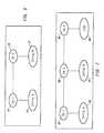
- Figs. 5a-5cprovide block schematic diagrams that illustrate three long term signature verification usage scenarios.
- a client (EntityA) 50submits a document to a LTSV facility 52 for long term signature verification. This is a simple case where EntityA is interested in documenting that it possessed some piece of information.
- EntityB 56receives a document from EntityA 54 and submits that document to the LTSV facility 58. In this case, EntityB wants to document that it received some information from EntityB.
- EntityA 60sends the same document to EntityB 64 and to the LTSV facility 62.
- This caserepresents a carbon copy feature, whereby EntityA can document the information it sent to EntityB by additionally filing it with the LTSV facility.
- a documentcan be encrypted and/or signed.
- the LTSV facilityaccepts any such document. This raises a problem, however, with respect to how the LTSV module works with respect to the encryption.
- the documentis effectively encrypted under the public key of the recipient, thereby guaranteeing that the recipient (the possessor of the corresponding private key) is the only entity which can decrypt the information. (For purposes of this discussion, interaction with symmetric keys and algorithms is ignored.)
- the latter approach aboveis presently the preferred approach.
- the first approach aboveraises significant security concerns because it requires distribution of an entity's private key.
- the second approach aboveis unacceptably restrictive on the usage of the system.
- Digital signature verificationis always performed between two (and only two) entities.
- the verification processis based upon (among other things) the trust relationship(s) in place between those two entities -- the originator (signer) and the recipient (verifier).
- Fig. 6is a block schematic diagram that illustrates trust between two entities according to the invention.
- EntityA 70has been issued a certificate by CA1 72
- EntityB 74has been issues a certificate by CA2 76
- CA's 1 and 2have been cross certified.
- a cross-certificateis a special type of certificate which indicates mutual trust between two CAs.
- the resulting trust modelsets up a path of trust between EntityA and EntityB, enabling them to verify digitally signed documents from one another successfully.
- a trust modelis comprised of the trust relationships among PKI entities (CAs and end users), embodied by the certificates and cross-certificates issues among these entities, as well as the underlying policies which enable this trust.) Note that if any of the three paths in this model were not in place, then sufficient trust would be lacking for the successful exchange of digitally signed messages between the two end parties. Signature verification would fail if any entity in this path is not trusted.
- This trust pathis commonly referred to as the certificate chain because it is composed of the certificates between the two entities.
- this entire trust path(among other things) which must be archived as part of the PKI state for later signature reverification.
- the trust path stored by the LTSV facilitymust contain the relevant trust information existing at the time of the request, not at some other time (before or after) where the trust relationships may be different between the entities. For example, a cross certificate between to CAs could either be created or removed at some point in time. This could effect the trust between two entities and affect the outcome of a signature verification.
- the time associated with the existing trust model between two entitiesis extremely important to the LTSV facility, but there are also ramifications with respect to how the LTSV module works -- specifically, what trust information is needed and stored by the LTSV component for later signature verification. This gets complicated when the LTSV component is included, which may or may not be trusted (via some trust path) by some entities.
- Scenario 1is fairly straightforward. There are only two entities involved. The trust path stored by the LTSV facility is the path between those two parties (EntityA and LTSV). It is assumed that trust exists between these entities, otherwise EntityA would not submit a request to that service.
- EntityBsends a request to the LTSV service, what signature does EntityB want to later verify? Most likely, EntityB wants to reverify EntityA's signature at a later time -- it wants the LTSV service to document that the signed document received from EntityA was valid (contained a valid signature) at the time it was received. This raises two general questions:
- Fig. 7is a block schematic diagram that illustrates a long term signature verification trust model.
- EntityB 84submits a signed document, received from EntityA 80, to the LTSV component 88
- the LTSVcan save the trust model embodied in the original signed document (EntityA 80 -> CA1 82 -> CA2 86 -> EntityB 84). Later verification of this signature recreates the verification process originally performed by EntityB when it received this document from EntityA. If, however, the PKI state stored by the LTSV service were to contain only the trust path between the submitter and the service (EntityB 84 -> CA2 86 -> CA3 90 -> LTSV 88), then reverification of the original document, as originally performed, is impossible. In fact, this is exactly the paradigm described in scenario 1, where the trust path between the submitter and the LTSV are of interest.
- the LTSVwould most likely store the trust path corresponding to the message from EntityA to EntityB (to reverify the signed document from EntityA to EntityB).
- the LTSVwould store the trust path corresponding to the submission itself -- from EntityA to the LTSV.
- scenario 3represents a case where flexibility in which trust path(s) to store is required.
- EntityA's submission to the LTSV facilitymay be with the intent to either reverify its correspondence with EntityB, or to reverify the submission itself (between EntityA and the LTSV).
- both trust pathsmay be of use to the client.
- the requirements on the LTSVare determined by the business of the particular application being deployed. For this reason, the interface to the LTSV preferably supports the ability of the client to indicate the needs in terms of trust paths as it impacts the requirements for later reverification.
Landscapes
- Engineering & Computer Science (AREA)
- Computer Security & Cryptography (AREA)
- Computer Networks & Wireless Communication (AREA)
- Signal Processing (AREA)
- Computer Hardware Design (AREA)
- Computing Systems (AREA)
- General Engineering & Computer Science (AREA)
- Storage Device Security (AREA)
- Management, Administration, Business Operations System, And Electronic Commerce (AREA)
Description
- This invention relates to a method and apparatus for the long term verification ofdigital signatures.
- The technology of digital signatures opens up the likelihood of increaseduse of digital networks (including the Internet) for electronic commerce. It isnow feasible to send and receive digitally signed documents that representtransactions of some value to one or more parties.
- Currently, a digital signature is verifiable only as long as the digitalcertificates upon which it depends have not expired. Given the expectationthat a certificate's life span is in the area of one to two years duration, currenttechnology does not support the emerging needs of the electronic commercemarket, where the durability of digital signatures over time is a requirement.
- For certain applications, the recipient of digitally signed documents shouldbe able to verify the authenticity of a document years after the document wassigned, just as the document's authenticity can be verified at the time ofsigning. Unfortunately, the current state of the technology does not providefor the verification of these digital signatures after certificate expirationbecause it is the nature of keys and certificates used for signing andencrypting documents to expire after a specific period of time (typically aftera year or two). This is due, at least in part, to the fact that the strength of keysis expected to degrade over time because of such factors as improvementsin computing speed and breakthroughs in cryptoanalysis. Moreover, thelonger the key is in use, the longer that an adversary has to attempt to crackthe key. Therefore, it is standard practice to replace keys periodically. Thisis why certificates have specific expiration dates.
- An examination of the current state of the technology reveals that a digitalsignature verification module would fail if presented with a request to verify asigned document in which any of the associated certificates had expired.Fig. 1 is a block schematic diagram illustrating certification expiration. Thissimple example demonstrates that, given a
certificate 10 having a two-yearlife span (e.g. from 4/1/96 to 4/1/98), a signature could be successfullyverified six months (e.g. on 10/1/96) after certificate issuance (100); but thissame signature would not be successfully verified three years later (e.g. on4/1/99) (102). This behavior is clearly unacceptable if the duration of adocument, for example contract, must extend beyond the duration of thecertificates' life. - Further, some current systems use certificate revocation lists (CRLs) torevoke certificates and remove them therefrom, once those certificatesexpire. This means that a record of those CRLs generally disappears,making long term signature verification impossible using known techniques.
- It is known to reconstruct past trust (see A. Menezes, P. van Oorschot, S.Vanstone,Handbook of Applied Cryptography, CRC Press, pp. 583 (1996)).In this approach, both signature reverification relative to a past point in timeand resolution of disputes may require reconstruction of chains of trust froma past point in time. This requires archival of keying material and relatedinformation for reconstruction of past chains of trust. Direct reconstruction ofsuch past chains is taught to be unnecessary if a notarizing agent is used. Anotarizing agent is defined as a general service capable not only ofascertaining the existence of a document at a certain time, but of vouchingfor the truth of more general statements at certain points in time. The originalverification of the notary is taught to establish the existence of a trust chain atthat point in time, and subsequently its record thereof is taught to serve asproof of prior validity. It is taught that details of the original trust chain may berecorded for audit purposes. It is not taught that a document can be verifiedbased upon the existence of expired certificates. Rather, reliance is placedupon the use of the notarizing agent. It is further taught that the archivedkeying material can be used as evidence at a future time to allow resolutionof disputed signatures by non-automated procedures.
- P. Zubeldia, and G. Romney,Method and apparatus for managing keyrevocation, EP 0 869 636 (01.04.1998), which falls under Art. 54(3) EPC, discloses an apparatus and methodfor accessing the validity status of a digital certificate even after a certificatehas expired. The certificate validity status is stored and retained in acertificate status history database that allows for ease of certificate statusretrieval. In addition, status historical information regarding multiple certificaterenewals, suspensions and reinstatements can also be obtained from thedatabase.
- Zubeldiaet al's disclosure teaches a method and apparatus that storescertificate status history. Zubeldiaet al does not teach or even suggest usingan archived PKI state to re-create the PKI state relative to a document at aselected time after a certificate has expired. Furthermore, Zubeldiaet al doesnot teach saving the PKI state in order to re-create the PKI state at a latertime to execute a signature verification process as it was or would have beenperformed earlier. Therein, reliance is placed solely upon the archival ofmaterial to reverify a signature, not re-creating the PKI state.
- A. M. Fischer,Public/key date-time notary facility, EP 0 422 757 (29.05.1990)discloses an apparatus and method for performing a time notarization in asecure way. It performs the time notarization so as to make it easy foranyone to verify notarization and to rely on the notarization time stamp. Inaddition, Fischer teaches a hardware platform that is encapsulated in asecure fashion so that the digital notary device's time stamping mechanism isnot feasibly subverted with or altered. The hardware platform includesinput/output means that receives a digital message to be digitally signed and time stamped. The input/output means returns the resulting time stampedsignature generated by the device to the presenter of the document, or storesthe digital time stamp, or disposes of it in any other appropriate means. Thehardware platform also includes a power source to ensure the accuracy of thedevice's digital clock and the security of stored data continuously during alltimes of the useful life of the device.
- Fischer's disclosure teaches a standalone device that performs notarizationdigitally. Fischer does not teach or even suggest verifying a document basedupon the existence of expired certificates. Herein, reliance is placed upon theuse of the notarizing agent.
- S. Chokhani, "Toward a National Public Key Infrastructure", IEEECommunication Magazine, Sept. 1994, 32(9), pp. 70-74, teaches that thepresent state of PKI implementation and claims that very little work has beendone in such area of PKI implementation. Chokani explores in some depththe concept of a nation-wide implementation of PKI. Chokani discusseschallenges to architecting the PKI. He says that PKI should be flexible andextensible to accommodate the addition of large numbers of users. He statesthe PKI implementation should be efficient from the end user's perspective, asthe end user may have to verify a chain of certificates in order to obtain thesender key. Therefore, he argues, the PKI implementation should bedesigned to minimize the certificate chain to be verified, because the processis computationally intensive. Nowhere does Chokhani teach or even suggestverifying a document based upon the existence of expired certificates.Reliance is placed upon certificates that are current.
- It would be advantageous to provide a technique for extending the time over which theauthenticity and integrity of digital signatures can be accurately verified beyond the time thatany relevant certificates expire.
- The present invention seeks to provide improved signature verification.
- According to an aspect of the present invention there is provided a method of enabling longterm verification of digital signatures as specified in
claim 1. - According to another aspect of the present invention there is provided apparatus as specifiedin claim 11.
- The prefered embodiment provides a method and apparatus which effectively extends thetime over which a digital signature can be verified,i.e. well beyond theexpiration of any or all of the certificates upon which that signature depends.The invention can be used for any application domain where users want digitalsignatures to be applied to long lasting documents (e.g. contracts), and beindependently verifiable years or decades after signing the document. Thepreferred embodiment provides two alternative approaches toconstructing a solution which delivers long term signature verification (LTSV).
- One embodiment of the invention provides an approach for solving the LTSVproblem that is referred to herein as the "save state" approach. Thisembodiment of the invention largely entails the use of cryptographic informationand techniques. Thus, an archive facility is used to store the public keyinfrastructure (PKI) state, e.g. cryptographic information, such as certificates andCRLS, in addition to the document itself. This information comprises all that isnecessary to re-create the signature verification process at a later time. It mayalso be desirable to store the source document separately from thecryptographic information (such as the signature, certificates, and CRLs) forreasons of privacy. For example, a user may want to have control over thesource document. The PKI state information may contain either or both of cryptographically protected information, such as certificates and CRLs, andinformation that is not cryptographically protected, such as the public key of aroot certification authority or policy information.
- When a user wants to reverify the signature on a document, possibly years later,an LTSV server re-creates the precise state of the PKI at the time the documentwas originally submitted. The LTSV server restores the state, and the signatureverification process executes the exact process it performed (or would haveperformed) years earlier. The time used as the basis for re-creation of thesignature verification process does not have to be the time of submittal. Rather,the time could be some other relevant time, such as when a document wassigned by the originator or when it was verified by a recipient.
- Another embodiment of the invention combines the strength of cryptographywith the proven resilience of (non-public key) technology and procedurescurrently associated with secure data stores. An example of this embodimentprovides a mechanism that:
- Saves the PKI state for future reverification; and
- Protects the PKI state information from intrusion by either maintaining it in asecure storage facility which is protected by services, such as firewalls,access control mechanisms, audit facilities, intrusion detection facilities,physical isolation, and network isolation; and/or employing a cryptographicprotection mechanism, for example using the LTSV server to sign the PKIstate information or using a keyed hash algorithm.
- In addition, other non-cryptographic features may be added to such approachesto deliver a highly secure and trusted LTSV solution, including, for exampleutilities for viewing the PKI state information (cryptographic as well asnon-cryptographic) and visually monitoring the security of the system. Theseutilities can be used to provide visual evidence for purposes of disputeresolution.
- One enhancement to the secure storage approach herein disclosed maintainscertain evidence, such as certificate chains, in an archive. This informationneed not be used for actual reverification, but merely as supporting evidence incase of a dispute.
- An embodiment of the present invention is described below, by way of example only, withreference to the accompanying drawings, in which:
- Fig. 1 is a block schematic diagram illustrating certification expiration;
- Fig. 2 is a block schematic diagram illustrating a "save state" embodiment of theinvention;
- Fig. 3 is a block schematic diagram illustrating a "save state" "secure storage"embodiment of the invention;
- Fig. 4 is a flow diagram that provides two alternative scenarios that illustrate theapplicability of time stamps to the preferred embodiments;
- Figs. 5a-5c provide block schematic diagrams that illustrate three long termsignature verification usage scenarios;
- Fig. 6 is a block schematic diagram that illustrates trust between two entities ; and
- Fig. 7 is a block schematic diagram that illustrates a long term signatureverification trust model.
- The meanings of some of the terms used herein may differ somewhat fromcommon usage. The following definitions are meant to clarify the meaning ofeach in the context of its usage herein.
- Archive: Any facility for the storage and retrieval of electronic information.
- Certificate: An artifact upon which digital signatures are based. A certificatesecurely binds an entity with that entity's public key.
- Cryptographic Refresh: A means of solving the key degradation problem whenstoring cryptographic information for long periods of time. The process involvesre-encoding the old cryptographic artifacts (e.g. encrypted data, digitalsignatures, and message digests) with stronger algorithms and/or longer keys.
- Document: A document can be any information which can be representedelectronically or optically (e.g. an arbitrary bit stream).
- Key Degradation/Algorithm Degradation: The process whereby the protectionafforded a document by encryption under a key loses effectiveness over time.For example, due to factors such as improvements in computing speed andbreakthroughs in cryptoanalysis, it is expected that a document securelyencrypted today would be crackable years later. This property could affect anycryptographic information, including digital signatures. This problem can begeneralized to keyed and non-keyed cryptographic processes and artifacts,such as one-way hash algorithms. The security provided by these are alsoexpected to diminish over time.
- LTSV: Long Term Signature Verification. The herein described method andapparatus for verifying a digital signature after the certificates used for suchverification have expired.
- LTSV client: The entity which requests/utilizes the services of the LTSV server.
- LTSV server: The entity which delivers the LTSV services. This does not imply,however, that this entity must be stand-alone component.
- LTSV submission: A request from an LTSV client to an LTSV server to performthe necessary functions required to enable reverification of a digital signaturesome time in the future (e.g. save PKI state).
- PKI: Public Key Infrastructure. Refers to all components, protocols, algorithms,and interfaces required to deliver the capabilities to digitally sign and verifydocuments. For purposes of clarity herein, a PKI does not include a servicemodule for long term signature verification (LTSV server), although in practice aPKI might be designed to encompass such a module.
- Signature Reverification: The re-creation of the digital signature verificationprocess after the original verification. This specifically refers to the processassociated with the verification process, based upon the restoration of thepreviously saved PKI state.
- Signature Verification: The process by which a digital signature, for a givendocument, is determined to be authentic or not.
- Signature Verification Module: The module which is responsible for performingthe verification of digital signatures.
- Time stamp: A digital time stamp is an electronic indicator which associates thecurrent date and time with a particular document. Time stamps are useful forproving that a document existed at a particular time. It is desirable that timestamps be secure, durable over time, and trusted by those using them.
- The discussion herein assumes an understanding of public key, digitalsignatures, and PKI infrastructure using X.509 certificates. Practical information concerning application of such techniques is considered to be well known tothose skilled in the art. Background information may be found, for example, inB. Schnier,Applied Cryptography: Protocols, Algorithms, and Source Code inC, John Wiley & Sons, Inc. (1996); W. Ford, M. Baum,Secure ElectronicCommerce, Prentice Hall PTR (1997); and in the X.509 v.3 specification ([X.509-AM]ISO/IEC JTC1/SC 21, Draft Amendments DAM 4 to ISO/IEC 9594-2,
DAM 2to ISO/IEC 9594-6,DAM 1 to ISO/IEC 9594-7, andDAM 1 to ISO/IEC 9594-8 onCertificate Extensions, 1 December 1996). The system i described herein maybe built upon the X.509 infrastructure. - The following discussion provides some background on cryptographictechniques. Cryptographic algorithms can generally be divided into twocategories: public key (e.g. RSA) and secret key (e.g. DES). Both types ofalgorithms transform plain text into cypher text using a key(s) for the encryptionand decryption processes.
- Both public key and secret key algorithms are considered to be secure. One isnot better than another in terms of security. The strength of each algorithm, interms of it being cracked, is largely a function of the length of the key used. Theprimary distinguishing characteristic of public key, however, is that it uses twokeys (one to encrypt and another to decrypt), while secret key algorithms useonly one key (the same key is used for encryption and decryption). For thisreason, secret key algorithms are sometime referred to as symmetric algorithmsand public key algorithms are called asymmetric.
- One problem with secret key algorithms is that a key must be distributedbetween all participants. This means that some secure channel must beavailable for the distribution of the keys.
- In practice, each entity in a public key-based system has a key pair,i.e. oneprivate key and one public key. The private key is known only to its owner, thepublic key is known to all correspondents. It is computationally infeasible todetermine a private key from the public key.
- The two primary services provided by public key cryptography are secureexchange of symmetric keys (by using public key techniques to encrypt asymmetric session key), and non-repudiation via digital signatures.
- Public key cryptography can be used to solve the key exchange problemassociated with secret key algorithms by using this technology to encrypt thesecret key under the public key of the recipient. It can then be decrypted by therecipient using his/her private key.
- Digital signatures are possible by encrypting data with the private key of thesigning entity. Any entity can decrypt it with the signer's publicly availablepublic key and know that no one else could have encrypted it because thatprivate key is only known by that one individual. This particular use of publickey provides the non-repudiation service, which is a primary use of public keycryptography. A digital signature is very powerful notion, it generally exhibitsthe following characteristics:
- Cannot be forged;
- Is independently verifiable;
- Is not reusable or transferable to a different piece of data; and
- Includes data integrity checks, allowing tamper-detection.
- The new services provided by public key cryptography do not come for free,however, because these services require the existence of a supporting publickey infrastructure. The strength of a public key system depends upon theassurance that all participants know the public key of any entity with whom theywish to correspond. If a secure correspondence between a user and his/herpublic key cannot be maintained, then it may be possible to impersonateanother entity or read encrypted data intended for another.
- The standard solution to this problem is the issuance of a digital certificate(X.509 certificate) to each participant. This certificate securely binds its owner'sname with his/her public key. It is issued by a trusted third party, called acertification authority (CA), and is signed by that CA, thereby making it tamperproof. Certificates are issued for a limited period of time (start and stop dates),during which the certificate is considered valid. A certificate is consideredexpired after the ending validity date.
- The public keys of entities (which are embedded in the X.509 certificates) mustbe publicly available. The distribution or access mechanisms available arenumerous.
- The secure operation of a public key infrastructure rests upon certain points oftrust. Certainly each entity must trust its own CA. However, when a given PKIdomain is expanded to encompass relationships with multiple CAs, the numberof points of trust are also expanded. The trust placed in a particular end entity(i.e. that entity's certificate or signature) is directly related to the trustrelationships among the CAs which certify those entities.
- CAs can create trust relationships with other CAs by certifying each other. Thiscan be a unidirectional trust relationship, whereby one CA can merely issues acertificate to another CA, just as a CA issues a certificate to an end user. TwoCAs can also mutually agree to trust each other (bidirectional trust relationship)by issuing a cross-certificate -- a special form of certificate which contain twoindividual certificates, one for each direction.
- If two entities are in the same CA domain, then there is no concern with respectto CA trust because they both trust the same CA. This is not the case, however,when dealing with the scenario where entities which have been certified bydifferent CAs attempt to conduct a secure transaction. The security of thistransaction depends upon the trust between the CAs. More generally, thesecurity provided by the PKI depends upon the trust models embodied in thetrust relationships among the various CAs which choose to trust one another. In concrete terms, any change in these trust relationships can cause a signatureverification to either succeed or fail.
- The preferred method and apparatus effectively extend thetime over which a digital signature can be verified,i.e. well beyond theexpiration of any or all of the certificates upon which that signature depends.They can be used for any application domain where users want digitalsignatures to be used on long lasting documents (e.g. contracts), and beindependently verifiable years or decades after signing the document. Thepreferred embodiment of the invention provides two alternative approaches toconstructing a solution which delivers long term signature verification (LTSV).
- Fig. 2 is a block schematic diagram illustrating a "save state" embodiment of theinvention. This embodiment, largely entails the use ofcryptographic information and techniques. Thus, an
archive facility 20 is used tostore a public key infrastructure (PKI)state 24,e.g. cryptographic information,such as certificates and CRLS, in addition to the source document itself. Forexample, theLTSV client 25 requests the services of anLTSV server 26 toaccomplish storage of such information. This step is shown as the "save state"step in Fig. 2. The PKI state information may contain either or both ofcryptographically protected information, such as certificates and CRLs, andinformation that is not cryptographically protected, such as the public key of aroot certification authority or policy information. - This information comprises all that is necessary to re-create the signatureverification process at a later time,i.e. during the "restore state" step, forexample, as requested by the LTSV client. It may also be desirable to store thesource document separately from the cryptographic information (such as thesignature, certificates, and CRLs) for reasons of privacy. For example, a usermay want to have control over the source document.
- When a user wants to reverify the signature on a document, possibly years later,the
LTSV server 26 re-creates the precise state of the PKI at the time thedocument was originally submitted. The LTSV server restores the state, and thesignature verification process 28 executes the exact process it performed (orwould have performed) years earlier. The time used as the basis for re-creationof the signature verification process does not have to be the time of submittal.Rather, the time could be some other relevant time, such as when a documentwas signed by the originator or when it was verified by a recipient. - Fig. 3 is a block schematic diagram illustrating a "save state" "secure storage"embodiment of the invention. This embodiment of the invention combines thestrength of cryptography with the proven resilience of (non-public key)technology and procedures currently associated with secure data stores. Anexample of this embodiment:
- Saves the PKI state for future reverification (as described above inconnection with Fig. 2); and
- Protects the PKI state information from intrusion by maintaining it in a securestorage facility which is protected by services, such as firewalls, accesscontrol mechanisms, audit facilities, intrusion detection facilities, physicalisolation, and network isolation; and/or employing a cryptographic protectionmechanism, for example using the LTSV server to sign the PKI stateinformation or using a keyed hash algorithm.
- In addition, other non-cryptographic features may be added to such approach todeliver a highly secure and trusted LTSV solution, including, for
exampleutilities 30 for viewing the PKI state information (cryptographic as well asnon-cryptographic) and visually monitoring the security of the system. Theseutilities can be used to provide visual evidence for purposes of disputeresolution. - One enhancement to the secure storage approach herein disclosed maintainscertain evidence, such as certificate chains, in an archive. This informationneed not be used for actual reverification, but merely as supporting evidence incase of a dispute. See A. Menezes, P. van Oorschot, S. Vanstone,Handbook ofApplied Cryptography, CRC Press, pp. 583 (1996), for one manner in which thisenhancement may be implemented in the context of a notary service (discussedabove).
- There are other embodiments of the invention in which a hybrid LTSV solutioncould be constructed by combining cryptographic and non-cryptographictechniques. The best combination for a particular application domain depends upon the security requirements of the application(s), in combination with costconstraints.
- It is presently preferred to employ the second embodiment of the invention(discussed above) due to the cryptographic strength associated with its ability tore-create the complete digital signature verification process, combined with thetrust instilled by more conventional techniques used for providing securestorage, and in conjunction with audit and viewing facilities with which to viewevidence and monitor the secure storage controls. In practice, the most usefulembodiment of the invention for a particular application may be that which is theleast expensive and which still meets the user or application requirements.
- Several issues related to the design of a system which implements LTSV aredescribed below. Alternatives for the resolution of the issues are presented, aswell as a discussion of the advantages and disadvantages associated with eachalternative. The best approach to any given solution depends upon the securityrequirements of the application(s) using the LTSV services, as well as the costconstraints. There is no best solution for all applications.
- Signature reverification is preferably associated with a particular time becausethe outcome of this process could change, depending upon the state of the PKI(e.g. because of certificate revocations or the creation/removal of crosscertificates). There are numerous possibilities with regard to when the PKI stateshould be saved, including:
- At signature creation time. This approach is used when an individual wantsto document the validity of his/her signature at the time it was created. This isthe most accurate time to store the PKI state because it reflects the state atthe time of signing, which is presumably the critical time in evaluating theauthenticity of that signature. Changes to the PKI state occur after that time,some of which could impact the outcome of a signature reverification.Therefore, saving of the PKI state at any time after signing introduces thepossibility of inconsistencies between the signer's and recipient'sperspectives on a signature's validity.
- At signature verification time. This approach is useful when a recipient wantsto document the validity of a signed document received from anotherindividual.
- At archival time. When a user decides that a document should be archivedfor long term storage is also an appropriate time to save the PKI state.
- When explicitly requested. There may occur certain application specificdocument life cycle milestones, at which time the user may desire the PKIstate to be saved for future reverification.
- Just before changes in PKI state (e.g. certificate revocation). This approachrequires a tight integration with the PKI because changes in the PKI must bemonitored.
- The correct time at which to save the PKI state is preferably determined by theconstraints and needs of the application using the LTSV services. A robustLTSV solution is able to accommodate the needs of all (or most) applications inthis respect.
- The exact composition of the PKI state varies somewhat from one PKI vendor'sproduct to another's, depending upon the implementation chosen by eachvendor. Moreover, certain information is stored in a different format from onevendor to another. In addition, the contents of a PKI state may change over timeas well, as new capabilities (and supporting data) are added to the system.Finally, the required contents of the PKI state may change from one applicationto another, depending upon the needs (e.g. level of security and legalrequirements) of each application.
- Notwithstanding these uncertainties, there are classes of PKI state informationwhich are candidates for saving. These classes include:
- Certificate chain (list of certificates from one entity to another, includingcertification authorities (CAs) and the end entities).
- CRLs (one for each CA in certificate chain).
- CA policy statements or identifiers.
- Attribute certificates.
- Date and time.
- Trust information (e.g., public key(s) or certificate(s) of trusted root CA(s),policy constraints).
- Policy constraints are, for example, non-cryptographic information stored withinthe LTSV archive. The public key of the trusted root CA may or may not becryptographically protected. If it is embedded in a certificate, then it is signed bythe CA. However, it could just as well be an isolated public key, in which case itis unprotected by cryptography.
- It is possible that the items in the above list may not be supported or availablefrom certain PKI implementations. Further, the PKI state from anotherimplementation might include some additional data. Therefore, the list above isonly an example of what might be considered important pieces of PKI stateinformation, given the current state of the technology. An implementation of anLTSV service is preferably tied to the implementation of a specific PKI until suchtime as the technology evolves and comprehensive standards emerge.
- Storage of the PKI state is preferably accomplished in either of two generalways:
- Store all of the PKI state relevant to each document separately;and
- Store the PKI state centrally, and only store references to the PKI stateinformation with each document. This approach enables storageefficiencies by eliminating the redundant storage of PKI state informationover multiple documents. For example, given two documents submitted tothe LTSV server at about the same time, it is possible that the CRLscontained in the PKI state are exactly the same for both submissions.Central storage of this information allows the LTSV server to store thisinformation only once.
- The storage requirements for the save state solution for LTSV may be quitelarge, depending upon the size of the certificates, the length of the certificatechains and -- more importantly -- the size of the CRLs. The choice of storagetechnique may have a great impact on the total data storage requirements. It isclearly undesirable to store massive CRLs with every document that is stored forlong term archival and possible future reverification. For this reason, the secondalternative listed above is presently considered to be the preferred approach.
- However, this second approach may present certain difficulties in applicationswhere the LTSV server is an entirely separate component from the PKI, andwhere support of multiple PKls is a primary design goal of the LTSV server. Inthis case, it would be advantageous for the PKI state to remain opaque to theLTSV server, thereby providing ease of support of multiple PKI vendors. Giventhat what constitutes the PKI state for one vendor may be different for another vendor, it is desirable to maintain an opaque interface between the LTSV serverand the PKI. On the other hand, storage efficiencies can be derived only if theLTSV server is informed about the contents and format of the PKI stateinformation. These conflicting requirements -- acceptable storage size andopaqueness -- pose a challenge for the design of an LTSV service.
- Some of the possible alternatives are listed below:
- Keep the interface opaque and store the PKI state as it currently exists (fullcertificate chains and CRLs). This option focuses entirely on the opaquenessrequirement, and sacrifices the data size requirement. The primaryadvantage of this solution is simplicity and quick deployment.
- Remove the opaqueness requirement by making the PKI state visible to theLTSV server. This allows the LTSV server to manage the certificates andCRLs manually -- thereby avoiding duplication of these objects in the datastore. This solution potentially sacrifices the ease of multi-vendor support atthe expense of achieving efficient storage.
- Compromise by making the CRLs visible to the LTSV server, where otherPKI state information is opaque. This solution is interesting because it isprobable that the CRLs are the largest piece of data comprising the PKIstate. Because CRLs are standard across nearly all PKls, the visibility shouldnot pose a problem in terms of multi-vendor support. This solution addressboth of the requirements, but does put the burden of management of theCRLs onto the LTSV server.
- An alternative embodiment of the invention provides a variation on thesolution above that breaks up the PKI state into multiple pieces, each ofwhich is opaque. The PKI indicates which of these objects is common acrossmultiple signed documents (e.g. CRLs and certificates). The PKI labels theseobjects with unique handles (identifiers), thereby allowing the LTSV serverto store these objects and retrieve them efficiently when needed forsignature reverification -- all the while maintaining the opaqueness of theseobjects.
- Encourage PKI vendors to make concise cryptographically protectedassertions about the state of revocation, as an alternative to using CRLs. (Forexample, CRLs indicate who has been revoked. It would be more efficient ifthe PKI could make a statement that a certificate has not been revoked at agiven point in time. This could eliminate the need for storing CRLs.) Thisapproach is non-standard, but acceptable because these PKI-generatedassertions are not seen by any application outside the PKI. A major benefit ofthis approach is that the opaqueness of the state is preserved while some ofthe storage inefficiencies of the state information are removed.
- For cases where the LTSV server is dedicated to a particular PKI, it is preferredto create a close integration between the two components, thereby allowing theLTSV server to know about the content and format of the PKI state information,and store it in the most efficient manner possible. For cases where the LTSVserver must be insulated from the PKI (e.g. for portability across multiple PKIs), one of the options listed above (with the possible exception of the first two) maybe used.
- The source data associated with an LTSV submission can be stored either bythe client or by the LTSV server itself. Some LTSV clients do not choose tosubmit clear text to the LTSV server for storage because of concerns overprivacy. (Privacy of the channel between the LTSV client and the LTSV servercan be achieved by having the client encrypt the submission under the publickey of the LTSV server.) A submission to the LTSV may be encrypted, such thatthe LTSV is not able to decrypt it. That is acceptable with the LTSV server.However, the client must determine how to decrypt the submission.
- Given that the LTSV server views the source data as a bit stream, it is possiblethat the message could be encrypted by the LTSV client before submission.(The fact that a general purpose LTSV server treats the source document as abit stream does not preclude the possibility of implementing an applicationspecific LTSV server that is aware of the contents of the submitted data.) TheLTSV server treats the encrypted data as the source. Such prior encoding maybe sufficient for some applications' needs for privacy. In this case, however,either the client must maintain the decryption key, or the key must be divulgedand stored by the LTSV server (which is probably not acceptable).
- Alternatively, the LTSV client may submit a message digest (resulting from aone-way hash function) as the source document. The client, in this case, is responsible for maintaining the real source document. If the source document isstored by the client, then only the PKI state information is stored in the LTSVserver's archive (along with some reference to the source document or thesubmitter).
- Whether the source data is stored by the client or the LTSV server, it must beproduced if and when a reverification of that document is required. It is arequired component of any signature verification process.
- If cryptographically encoded information (e.g. digital signatures or encrypteddata) is stored for a significant period of time, the issue of key and algorithmdegradation must be addressed,i.e. the probable loss in effectiveness of acryptographic key or algorithm over time. Although signed documents areexpected to be sealed securely with strong cryptographic algorithms, thestrength of an algorithm and associated key length decreases over time with theadvent of faster computers and new developments in cryptoanalysis. It isexpected that cryptographic algorithms and key lengths have limited life spans.It is generally acknowledged that they should be examined, modified, and/orreplaced at periodic intervals. This legitimate security concern increases withthe length of time for which a document is valid, and it becomes a very seriousthreat as the time span approaches multiple decades.
- For example, a digital signature performed today, using RSA and a 512-bit key,is considered very strong (i.e. it would take years to forge it). But, it is also expected that this same signature may be easily forgeable within ten years orso. This is because of the increased ability to search the key space faster (andthereby find the key used to sign the message) with newer computers orcomputing techniques. Similarly, there may continue to be developments intechniques for factoring large prime numbers (the difficulty of which is the basisfor the strength of the RSA algorithm). It is reasonable for both of these abilitiesto improve over time (although the pace of these changes is less certain).
- It is, therefore, prudent to protect cryptographically encoded documents from thisthreat when those documents must live beyond a few years. This is the casewith the documents expected to be submitted to the LTSV server, and especiallyso when using the save state approach herein disclosed. Hence, the LTSVfacility should address this problem. Not only must the signed documentsstored in the archive be protected from this threat, but all other cryptographicdata or meta-data stored in the archive should be protected. (The cryptographicdata primarily include keyed information. That is, any information that is signedor encrypted with a private key. Such information may also include non-keyedcryptographic data, such as the output from a hash algorithm, such as MD5.)This data could also include such items as certificates and CRLs, which are,themselves, digitally signed by the issuing CA.
- There are any number of ways that the LTSV facility addresses this problem. Forexample:
- Periodically countersign all data in need of cryptographic refresh through theuse of nested signatures. Under this approach, the LTSV server effectively refreshes the cryptographic strength of the data by signing it withsuccessively longer keys (or stronger algorithms) every few years. Eachcounter signature has the effect of locking in the cryptographic strength of theenclosed signature(s), thereby extending the cryptographic life of theenclosed document. This countersignature is preferably performed by theLTSV server using a key owned by that server. Performance shortcuts maybe required to avoid the costly unraveling of signatures at reverification time,or the potentially time consuming task of countersigning every document inthe archive. Such shortcuts include, for example, removing a previouscountersignature before applying a new one, or countersigning the entirearchive or portions thereof instead of each individual document.
- A modification of the cryptographic approach suggested above provides forcountersigning the information in the archive once, but with an extremelylong key,i.e. a key which is expected to be unbreakable for decades ormore. This eliminates all need for countersigning. This may be merely atheoretical solution because finding an algorithm and key length which issecure for that long is impossible to predict. Therefore, there is still a need toprovide some backup mechanism, just in case the original algorithm werecracked, for example.
- Protect the cryptographic information in the archive by insulating the archiveitself, rather than the individual documents contained in the archive, therebyeliminating the need for a cryptographic solution. In this approach, thearchive is protected via access controls and other procedural controls. If the archive can be effectively insulated from intrusion and modification, then keydegradation is not an issue and cryptographic refresh is not necessary.
- Use a time stamp facility to seal the cryptographic information in time. Such afacility is expected to provide all of the necessary characteristics required forsolving the key degradation problem. This time stamp facility could use oneof the techniques listed above, or it could even be an independent service(see below for a discussion of time stamping).
- A secure and comprehensive LTSV solution preferably includes an associationwith a time stamping mechanism. For long term verification of digital signatures,it is often necessary to know the time at which particular events occurred (e.g.time of signing or verifying a signature) to determine if a document was valid atthat specific time. If there were uncertainty concerning when a document wassigned, then the later reverification of that document could be compromisedbecause of the uncertainty of when it was signed.
- Fig. 4 is a flow diagram that provides two alternative scenarios that illustrate theapplicability of time stamps.
- In scenario 1:
- Alice signs a document at time T1, and sends it to Bob (140).
- Alice's certificate is revoked at time T2 (142).
- Bob verifies Alice's signature at time T3 (144).
- In scenario 2:
- Alice's certificate is revoked at time T1 (150).
- Alice signs a document at time T2, and sends it to Bob (152).
- Bob verifies Alice's signature at time T3 (154).
- When Bob performs the verification (at time T3), he does not know when Alicesigned the document. This is critical, because if Alice's key (certificate) wererevoked before signing the message, then the signature verification by Bobshould fail, and Bob should not trust the contents of the message. If, on the otherhand, the revocation occurred after the act of signing, then the signature can bepresumed to be valid and trustworthy. For simplicity, this example does notconsider the complicating issue of CRL latency,i.e. the time between theinitiation of certificate revocation and the time when this information becomesavailable on a CRL.
- This example demonstrates the need for a secure and trusted time stampmechanism in the domain of digital signatures. The mere recording of thecurrent date and time when creating a digital signature is not sufficient for mostapplication because the source of that time may not be trusted by the recipient.The impact, however, also applies not only to the short term signatureverification process, but also to the long term verification of digital signatures.Given the example above, the LTSV server could save the PKI state (at time T1)associated with
scenario 1 or scenario 2 (or both). The outcome of a signatureverification on this message years later is greatly affected by the PKI state usedfor this verification process, as well as the target time for the verification. - The problem highlighted above demonstrates the preference that the LTSVservice to be cognizant of time. It should:
- Be able to determine in a secure fashion the time at which a document wasoriginally signed;
- Be able to re-create accurately the PKI state which was active at a target timein the past;
- Be able to determine the current date and time accurately; and
- At a minimum, save the PKI state associated with a particular target time.
- These requirements establish the preference for the integration of a time stampfacility with the signing and verification (and reverification) process. When a document is signed, it is also preferably time stamped to document in a securefashion the precise moment at which that event occurred. The LTSV serviceshould know the time for which the PKI state is to be saved, be sure to save theappropriate state (the state active at the target time), and execute its signaturereverification process in the context of the correct time.
- Figs. 5a-5c provide block schematic diagrams that illustrate three long termsignature verification usage scenarios.
- In
scenario 1, a client (EntityA) 50 submits a document to aLTSV facility 52 forlong term signature verification. This is a simple case where EntityA is interestedin documenting that it possessed some piece of information. - In
scenario 2,EntityB 56 receives a document fromEntityA 54 and submits thatdocument to theLTSV facility 58. In this case, EntityB wants to document that itreceived some information from EntityB. - In
scenario 3,EntityA 60 sends the same document toEntityB 64 and to theLTSV facility 62. This case represents a carbon copy feature, whereby EntityAcan document the information it sent to EntityB by additionally filing it with theLTSV facility. - Each of the scenarios described above raises issues with respect to encryption,private key access, and trust models.
- A document can be encrypted and/or signed. Ideally, the LTSV facility acceptsany such document. This raises a problem, however, with respect to how theLTSV module works with respect to the encryption. When encrypting under apublic key system, the document is effectively encrypted under the public key ofthe recipient, thereby guaranteeing that the recipient (the possessor of thecorresponding private key) is the only entity which can decrypt the information.(For purposes of this discussion, interaction with symmetric keys and algorithmsis ignored.)
- When applying this principle to
scenario 1, it is clear that if the signed messageis also encrypted, then it could be encrypted under the public key of the LTSVmodule. This allows the LTSV component to unwrap the signed document andpreserve it for long term verification. This is a useful feature because it providesconfidentiality between EntityA and the LTSV service. This scenario does notpreclude the possibility that the source document sent signed and encrypted tothe LTSV module could itself be encrypted under a key known only to EntityA.That is, it is not necessary that the LTSV have access to the plain text version ofthe source document. The LTSV module treats that encrypted document as thesource. If EntityA does decide to encrypt the document first under a secret keybefore submitting the document to the LTSV service, then it is the responsibilityof EntityA to maintain possession of that key if and when decryption of thatdocument is required. - In
Scenario 2, if the message from EntityA to EntityB is encrypted (under thepublic key of EntityB) and then forwarded -- unchanged -- to the LTSV serviceby EntityB, then it is unreadable by the LTSV component because it does notpossess the private key required to decipher and unwrap the enclosed signeddocument. This unwrapping (decipherment) is essential for the LTSV module todo its job. - There exist several alternatives for addressing this problem:
- Allow the LTSV facility to have access to EntityB's private key;
- Do not allow EntityA to send encrypted documents to EntityB; or
- Have EntityB strip off the privacy aspect of the signed and encrypteddocument received from EntityA. Because EntityB wants to preserveEntityA's signature on the document, and be able to verify it at a later time,this stripping process can not alter the validity of the signature. EntityA canthen either send the stripped (i.e. plain text) document to the LTSV service,or it can re-encrypt it (still preserving the original signature by EntityA) underthe public key of the LTSV module.
- The latter approach above is presently the preferred approach. The firstapproach above raises significant security concerns because it requiresdistribution of an entity's private key. The second approach above isunacceptably restrictive on the usage of the system.
- Digital signature verification is always performed between two (and only two)entities. The verification process is based upon (among other things) the trustrelationship(s) in place between those two entities -- the originator (signer) andthe recipient (verifier).
- Fig. 6 is a block schematic diagram that illustrates trust between two entitiesaccording to the invention. In this situation,
EntityA 70 has been issued acertificate byCA1 72,EntityB 74 has been issues a certificate byCA2 76, andCA's 1 and 2 have been cross certified. (A cross-certificate is a special type ofcertificate which indicates mutual trust between two CAs.) The resulting trustmodel sets up a path of trust between EntityA and EntityB, enabling them toverify digitally signed documents from one another successfully. (A trust modelis comprised of the trust relationships among PKI entities (CAs and end users),embodied by the certificates and cross-certificates issues among these entities,as well as the underlying policies which enable this trust.) Note that if any of thethree paths in this model were not in place, then sufficient trust would be lackingfor the successful exchange of digitally signed messages between the two endparties. Signature verification would fail if any entity in this path is not trusted. - This trust path is commonly referred to as the certificate chain because it iscomposed of the certificates between the two entities. When considering thesave state approach to long term signature verification, it is this entire trust path(among other things) which must be archived as part of the PKI state for latersignature reverification. Moreover, the trust path stored by the LTSV facility must contain the relevant trust information existing at the time of the request, not atsome other time (before or after) where the trust relationships may be differentbetween the entities. For example, a cross certificate between to CAs couldeither be created or removed at some point in time. This could effect the trustbetween two entities and affect the outcome of a signature verification.
- As discussed above, the time associated with the existing trust model betweentwo entities is extremely important to the LTSV facility, but there are alsoramifications with respect to how the LTSV module works -- specifically, whattrust information is needed and stored by the LTSV component for latersignature verification. This gets complicated when the LTSV component isincluded, which may or may not be trusted (via some trust path) by someentities.
- Consider the three scenarios illustrated in Figs. 5a-5c:
Scenario 1 is fairly straightforward. There are only two entities involved. Thetrust path stored by the LTSV facility is the path between those two parties(EntityA and LTSV). It is assumed that trust exists between these entities,otherwise EntityA would not submit a request to that service.Scenario 2, however, raises certain issues. When EntityB sends a request to theLTSV service, what signature does EntityB want to later verify? Most likely,EntityB wants to reverify EntityA's signature at a later time -- it wants the LTSVservice to document that the signed document received from EntityA was valid (contained a valid signature) at the time it was received. This raises two generalquestions:- Whether the LTSV service is trusted by EntityA. It can be assumed that thecommunicating parties (EntityA with EntityB, and EntityB with the LTSV) havedeveloped some trust between themselves. But in this case, it is possiblethat there exists no trust path between EntityA and the LTSV component.
- The trust path that is to be stored by the LTSV facility. There exist threepossible trust paths which can be stored by the LTSV,i.e. the path betweenEntities A and B; the path between EntityB and the LTSV component itself;and the path between EntityA and the LTSV component, if it exists.
- Fig. 7 is a block schematic diagram that illustrates a long term signatureverification trust model. Given
scenario 2, whereEntityB 84 submits a signed document, received fromEntityA 80, to theLTSVcomponent 88, the LTSV can save the trust model embodied in the originalsigned document (EntityA 80 -> CA1 82 -> CA2 86 -> EntityB 84). Laterverification of this signature recreates the verification process originallyperformed by EntityB when it received this document from EntityA. If, however,the PKI state stored by the LTSV service were to contain only the trust pathbetween the submitter and the service (EntityB 84 -> CA2 86 -> CA3 90 -> LTSV88), then reverification of the original document, as originally performed, isimpossible. In fact, this is exactly the paradigm described inscenario 1, wherethe trust path between the submitter and the LTSV are of interest. - The above discussion reveals that there are good reasons for the LTSVcomponent to be able to store either trust path, depending upon therequirements of the client.
- In
scenario 2, the LTSV would most likely store the trust path corresponding tothe message from EntityA to EntityB (to reverify the signed document fromEntityA to EntityB). Inscenario 1, the LTSV would store the trust pathcorresponding to the submission itself -- from EntityA to the LTSV. - Similarly,
scenario 3 represents a case where flexibility in which trust path(s) tostore is required. In this case, EntityA's submission to the LTSV facility may bewith the intent to either reverify its correspondence with EntityB, or to reverify thesubmission itself (between EntityA and the LTSV). In fact, both trust paths maybe of use to the client. The requirements on the LTSV are determined by thebusiness of the particular application being deployed. For this reason, theinterface to the LTSV preferably supports the ability of the client to indicate theneeds in terms of trust paths as it impacts the requirements for laterreverification.
Claims (12)
- A method of enabling long term verification of digital signatures, comprisingthe steps of:submitting a source document or digest thereof to a signature verification entity;using a long term signature verification server to store a public key infrastructure,hereinafter referred to as PKI, state necessary to re-create a signature verification processat a later time relative to said document at a selected archival time; andusing said archived PKI state in said long term signature verification server to re-createsaid PKI state to execute exactly said signature verification process performedearlier relative to said document at a selected time after a certificate associated with saidsignature has expired.
- A method as in claim 1, wherein the time over which a digital signature associatedwith said document can be verified is extended beyond expiration of any or all of anycertificates upon which that signature depends.
- A method as in claim 1 or 2 comprising the step of:storing said source document separately from any associated cryptographicinformation.
- A method as in claim 1, 2 or 3 wherein the selected archival time used as thebasis for subsequent re-creation of a signature verification process is the time of saidsource document submittal;
is the time when said source document was signed by its originator; or is the timewhen said source document was verified by a recipient. - A method as in any preceding claim, comprising the step of;
protecting said PKI state information from intrusion by maintaining it in a securestorage facility preferably comprising of at least one of a firewall, access controlmechanism, audit facility, intrusion detection facility, physical isolation and network isolation; or protecting non-cryptographic PKI state information from intrusion byprotecting it in an archive via any of a signature and keyed hash algorithm. - A method as in any preceding claim comprising the step of:providing utilities for viewing said PKI state information and for visuallymonitoring system security.
- A method as in any preceding claim, wherein classes of PKI state informationmay include one or more of certificate chain from one entity to another, includingcertification authorities (CAs) and the end entities; certificate revocation lists (CRLs),one for each CA in certificate chain; certificate practice statements; attribute certificates;policy constraints; trust information; and date and time.
- A method as in any preceding claim, comprising the step of:periodically countersigning all data in need of cryptographic refresh through theuse of nested signatures and/or countersigning information in said archive facility oncewith an extremely long key.
- A method as in any preceding claim, comprising at least one of the steps of:protecting said archive facility itself, rather than individual documents containedin said archive; andemploying a cryptographic protection mechanism at said signature verificationentity.
- A method as in any preceding claim, comprising the step of:using a time stamp facility to seal cryptographic information in time.
- Apparatus for long term verification of digital signature, comprising:wherein said archived PKI state in said long term signature verification server isused to re-create said PKI state to execute exactly said signature verification processperformed earlier relative to said document at a selected time after a certificate associatedwith said signature has expired.a source document;a long term signature verification server for storing a public key infrastructure,herein after referred to as PKI, state necessary to re-create a signature verificationprocess at a later time relative to said document at a selected archival time; and
- Apparatus as in claim 11, comprising:either of a signature and a keyed hash system for protecting non-cryptographicPKI state information from undetected modification, wherein said non-cryptographic PKIstate information is maintained in an archive.
Applications Claiming Priority (2)
| Application Number | Priority Date | Filing Date | Title |
|---|---|---|---|
| US08/892,792US6584565B1 (en) | 1997-07-15 | 1997-07-15 | Method and apparatus for long term verification of digital signatures |
| US892792 | 1997-07-15 |
Publications (3)
| Publication Number | Publication Date |
|---|---|
| EP0892521A2 EP0892521A2 (en) | 1999-01-20 |
| EP0892521A3 EP0892521A3 (en) | 2000-03-22 |
| EP0892521B1true EP0892521B1 (en) | 2003-01-02 |
Family
ID=25400496
Family Applications (1)
| Application Number | Title | Priority Date | Filing Date |
|---|---|---|---|
| EP98305646AExpired - LifetimeEP0892521B1 (en) | 1997-07-15 | 1998-07-15 | Method and apparatus for long term verification of digital signatures |
Country Status (4)
| Country | Link |
|---|---|
| US (1) | US6584565B1 (en) |
| EP (1) | EP0892521B1 (en) |
| JP (1) | JPH11119650A (en) |
| DE (1) | DE69810394T2 (en) |
Cited By (52)
| Publication number | Priority date | Publication date | Assignee | Title |
|---|---|---|---|---|
| US6907600B2 (en) | 2000-12-27 | 2005-06-14 | Intel Corporation | Virtual translation lookaside buffer |
| US6934817B2 (en) | 2000-03-31 | 2005-08-23 | Intel Corporation | Controlling access to multiple memory zones in an isolated execution environment |
| US6941458B1 (en) | 2000-03-31 | 2005-09-06 | Intel Corporation | Managing a secure platform using a hierarchical executive architecture in isolated execution mode |
| US6986052B1 (en) | 2000-06-30 | 2006-01-10 | Intel Corporation | Method and apparatus for secure execution using a secure memory partition |
| US6990579B1 (en) | 2000-03-31 | 2006-01-24 | Intel Corporation | Platform and method for remote attestation of a platform |
| US6996748B2 (en) | 2002-06-29 | 2006-02-07 | Intel Corporation | Handling faults associated with operation of guest software in the virtual-machine architecture |
| US6996710B1 (en) | 2000-03-31 | 2006-02-07 | Intel Corporation | Platform and method for issuing and certifying a hardware-protected attestation key |
| US7013484B1 (en) | 2000-03-31 | 2006-03-14 | Intel Corporation | Managing a secure environment using a chipset in isolated execution mode |
| US7020738B2 (en) | 2000-12-27 | 2006-03-28 | Intel Corporation | Method for resolving address space conflicts between a virtual machine monitor and a guest operating system |
| US7024555B2 (en) | 2001-11-01 | 2006-04-04 | Intel Corporation | Apparatus and method for unilaterally loading a secure operating system within a multiprocessor environment |
| US7058807B2 (en) | 2002-04-15 | 2006-06-06 | Intel Corporation | Validation of inclusion of a platform within a data center |
| US7073042B2 (en) | 2002-12-12 | 2006-07-04 | Intel Corporation | Reclaiming existing fields in address translation data structures to extend control over memory accesses |
| US7076669B2 (en) | 2002-04-15 | 2006-07-11 | Intel Corporation | Method and apparatus for communicating securely with a token |
| US7076802B2 (en) | 2002-12-31 | 2006-07-11 | Intel Corporation | Trusted system clock |
| US7082615B1 (en) | 2000-03-31 | 2006-07-25 | Intel Corporation | Protecting software environment in isolated execution |
| US7089418B1 (en) | 2000-03-31 | 2006-08-08 | Intel Corporation | Managing accesses in a processor for isolated execution |
| US7096497B2 (en) | 2001-03-30 | 2006-08-22 | Intel Corporation | File checking using remote signing authority via a network |
| US7103771B2 (en) | 2001-12-17 | 2006-09-05 | Intel Corporation | Connecting a virtual token to a physical token |
| US7111176B1 (en) | 2000-03-31 | 2006-09-19 | Intel Corporation | Generating isolated bus cycles for isolated execution |
| US7117376B2 (en) | 2000-12-28 | 2006-10-03 | Intel Corporation | Platform and method of creating a secure boot that enforces proper user authentication and enforces hardware configurations |
| US7124327B2 (en) | 2002-06-29 | 2006-10-17 | Intel Corporation | Control over faults occurring during the operation of guest software in the virtual-machine architecture |
| US7127548B2 (en) | 2002-04-16 | 2006-10-24 | Intel Corporation | Control register access virtualization performance improvement in the virtual-machine architecture |
| US7139890B2 (en) | 2002-04-30 | 2006-11-21 | Intel Corporation | Methods and arrangements to interface memory |
| US7165181B2 (en) | 2002-11-27 | 2007-01-16 | Intel Corporation | System and method for establishing trust without revealing identity |
| US7177967B2 (en) | 2003-09-30 | 2007-02-13 | Intel Corporation | Chipset support for managing hardware interrupts in a virtual machine system |
| US7215781B2 (en) | 2000-12-22 | 2007-05-08 | Intel Corporation | Creation and distribution of a secret value between two devices |
| US7237051B2 (en) | 2003-09-30 | 2007-06-26 | Intel Corporation | Mechanism to control hardware interrupt acknowledgement in a virtual machine system |
| US7272831B2 (en) | 2001-03-30 | 2007-09-18 | Intel Corporation | Method and apparatus for constructing host processor soft devices independent of the host processor operating system |
| US7287197B2 (en) | 2003-09-15 | 2007-10-23 | Intel Corporation | Vectoring an interrupt or exception upon resuming operation of a virtual machine |
| US7305592B2 (en) | 2004-06-30 | 2007-12-04 | Intel Corporation | Support for nested fault in a virtual machine environment |
| US7308576B2 (en) | 2001-12-31 | 2007-12-11 | Intel Corporation | Authenticated code module |
| US7318235B2 (en) | 2002-12-16 | 2008-01-08 | Intel Corporation | Attestation using both fixed token and portable token |
| US7356735B2 (en) | 2004-03-30 | 2008-04-08 | Intel Corporation | Providing support for single stepping a virtual machine in a virtual machine environment |
| US7366305B2 (en) | 2003-09-30 | 2008-04-29 | Intel Corporation | Platform and method for establishing trust without revealing identity |
| US7392415B2 (en) | 2002-06-26 | 2008-06-24 | Intel Corporation | Sleep protection |
| US7395405B2 (en) | 2005-01-28 | 2008-07-01 | Intel Corporation | Method and apparatus for supporting address translation in a virtual machine environment |
| US7424709B2 (en) | 2003-09-15 | 2008-09-09 | Intel Corporation | Use of multiple virtual machine monitors to handle privileged events |
| US7480806B2 (en) | 2002-02-22 | 2009-01-20 | Intel Corporation | Multi-token seal and unseal |
| US7490070B2 (en) | 2004-06-10 | 2009-02-10 | Intel Corporation | Apparatus and method for proving the denial of a direct proof signature |
| US7516330B2 (en) | 2000-06-28 | 2009-04-07 | Intel Corporation | Platform and method for establishing provable identities while maintaining privacy |
| US7620949B2 (en) | 2004-03-31 | 2009-11-17 | Intel Corporation | Method and apparatus for facilitating recognition of an open event window during operation of guest software in a virtual machine environment |
| US7802085B2 (en) | 2004-02-18 | 2010-09-21 | Intel Corporation | Apparatus and method for distributing private keys to an entity with minimal secret, unique information |
| US7818808B1 (en) | 2000-12-27 | 2010-10-19 | Intel Corporation | Processor mode for limiting the operation of guest software running on a virtual machine supported by a virtual machine monitor |
| US7840962B2 (en) | 2004-09-30 | 2010-11-23 | Intel Corporation | System and method for controlling switching between VMM and VM using enabling value of VMM timer indicator and VMM timer value having a specified time |
| US8014530B2 (en) | 2006-03-22 | 2011-09-06 | Intel Corporation | Method and apparatus for authenticated, recoverable key distribution with no database secrets |
| US8037314B2 (en) | 2003-12-22 | 2011-10-11 | Intel Corporation | Replacing blinded authentication authority |
| US8078542B2 (en) | 2001-06-07 | 2011-12-13 | Contentguard Holdings, Inc. | System and method for managing transfer of rights using shared state variables |
| US8146078B2 (en) | 2004-10-29 | 2012-03-27 | Intel Corporation | Timer offsetting mechanism in a virtual machine environment |
| US8156343B2 (en) | 2003-11-26 | 2012-04-10 | Intel Corporation | Accessing private data about the state of a data processing machine from storage that is publicly accessible |
| US8386788B2 (en) | 2002-02-25 | 2013-02-26 | Intel Corporation | Method and apparatus for loading a trustable operating system |
| US8924728B2 (en) | 2004-11-30 | 2014-12-30 | Intel Corporation | Apparatus and method for establishing a secure session with a device without exposing privacy-sensitive information |
| CN107294706A (en)* | 2017-06-09 | 2017-10-24 | 飞天诚信科技股份有限公司 | It is a kind of to support the endorsement method of long-term checking signature, sign server and system |
Families Citing this family (114)
| Publication number | Priority date | Publication date | Assignee | Title |
|---|---|---|---|---|
| JPH08263438A (en) | 1994-11-23 | 1996-10-11 | Xerox Corp | Distribution and use control system of digital work and access control method to digital work |
| US6963859B2 (en) | 1994-11-23 | 2005-11-08 | Contentguard Holdings, Inc. | Content rendering repository |
| US7162635B2 (en) | 1995-01-17 | 2007-01-09 | Eoriginal, Inc. | System and method for electronic transmission, storage, and retrieval of authenticated electronic original documents |
| US6367013B1 (en)* | 1995-01-17 | 2002-04-02 | Eoriginal Inc. | System and method for electronic transmission, storage, and retrieval of authenticated electronic original documents |
| US7743248B2 (en) | 1995-01-17 | 2010-06-22 | Eoriginal, Inc. | System and method for a remote access service enabling trust and interoperability when retrieving certificate status from multiple certification authority reporting components |
| US6233684B1 (en) | 1997-02-28 | 2001-05-15 | Contenaguard Holdings, Inc. | System for controlling the distribution and use of rendered digital works through watermaking |
| US6044462A (en)* | 1997-04-02 | 2000-03-28 | Arcanvs | Method and apparatus for managing key revocation |
| EP1159799B1 (en)* | 1999-02-26 | 2006-07-26 | Bitwise Designs, Inc. | Digital file management and imaging system and method including secure file marking |
| US6937726B1 (en) | 1999-04-06 | 2005-08-30 | Contentguard Holdings, Inc. | System and method for protecting data files by periodically refreshing a decryption key |
| US6629150B1 (en)* | 1999-06-18 | 2003-09-30 | Intel Corporation | Platform and method for creating and using a digital container |
| NL1012435C2 (en)* | 1999-06-25 | 2000-12-28 | Koninkl Kpn Nv | System for secure storage and management in a TTP server. |
| WO2001011819A1 (en)* | 1999-08-09 | 2001-02-15 | Koninklijke Philips Electronics N.V. | Updating a revocation list to foil an adversary |
| US8538893B1 (en)* | 1999-10-01 | 2013-09-17 | Entrust, Inc. | Apparatus and method for electronic transaction evidence archival and retrieval |
| US7143144B2 (en)* | 1999-11-30 | 2006-11-28 | Ricoh Company, Ltd. | System, method and computer readable medium for certifying release of electronic information on an internet |
| US6757824B1 (en)* | 1999-12-10 | 2004-06-29 | Microsoft Corporation | Client-side boot domains and boot rules |
| EP1111838B1 (en)* | 1999-12-21 | 2006-04-05 | ContentGuard Holdings, Inc. | System and method for cryptographically protecting data |
| US6775657B1 (en)* | 1999-12-22 | 2004-08-10 | Cisco Technology, Inc. | Multilayered intrusion detection system and method |
| US7047404B1 (en)* | 2000-05-16 | 2006-05-16 | Surety Llc | Method and apparatus for self-authenticating digital records |
| JP4631132B2 (en)* | 2000-06-05 | 2011-02-16 | 三菱電機株式会社 | Digital signature validity period extension system, digital signature validity period extension device, and digital signature validity period extension method |
| AU2001288309A1 (en)* | 2000-08-18 | 2002-03-04 | Distributed Trust Management Inc. | Distributed information system and protocol for affixing electronic signatures and authenticating documents |
| US8225414B2 (en) | 2000-08-28 | 2012-07-17 | Contentguard Holdings, Inc. | Method and apparatus for identifying installed software and regulating access to content |
| US7743259B2 (en) | 2000-08-28 | 2010-06-22 | Contentguard Holdings, Inc. | System and method for digital rights management using a standard rendering engine |
| US6854056B1 (en)* | 2000-09-21 | 2005-02-08 | International Business Machines Corporation | Method and system for coupling an X.509 digital certificate with a host identity |
| US7343324B2 (en) | 2000-11-03 | 2008-03-11 | Contentguard Holdings Inc. | Method, system, and computer readable medium for automatically publishing content |
| JP4137370B2 (en)* | 2000-12-19 | 2008-08-20 | 株式会社リコー | Secure electronic media management method |
| US7225441B2 (en) | 2000-12-27 | 2007-05-29 | Intel Corporation | Mechanism for providing power management through virtualization |
| US6912294B2 (en) | 2000-12-29 | 2005-06-28 | Contentguard Holdings, Inc. | Multi-stage watermarking process and system |
| JP2002207428A (en)* | 2001-01-10 | 2002-07-26 | Mitsubishi Electric Corp | Signature expiration date extension device, signature expiration date verification device, signature expiration date extension system, signature expiration date extension method, recording medium recording signature expiration date extension program |
| US7028009B2 (en) | 2001-01-17 | 2006-04-11 | Contentguardiholdings, Inc. | Method and apparatus for distributing enforceable property rights |
| US7774279B2 (en) | 2001-05-31 | 2010-08-10 | Contentguard Holdings, Inc. | Rights offering and granting |
| US8069116B2 (en) | 2001-01-17 | 2011-11-29 | Contentguard Holdings, Inc. | System and method for supplying and managing usage rights associated with an item repository |
| US8275709B2 (en) | 2001-05-31 | 2012-09-25 | Contentguard Holdings, Inc. | Digital rights management of content when content is a future live event |
| US7725401B2 (en) | 2001-05-31 | 2010-05-25 | Contentguard Holdings, Inc. | Method and apparatus for establishing usage rights for digital content to be created in the future |
| US8099364B2 (en) | 2001-05-31 | 2012-01-17 | Contentguard Holdings, Inc. | Digital rights management of content when content is a future live event |
| US8001053B2 (en) | 2001-05-31 | 2011-08-16 | Contentguard Holdings, Inc. | System and method for rights offering and granting using shared state variables |
| US6895503B2 (en) | 2001-05-31 | 2005-05-17 | Contentguard Holdings, Inc. | Method and apparatus for hierarchical assignment of rights to documents and documents having such rights |
| US8275716B2 (en) | 2001-05-31 | 2012-09-25 | Contentguard Holdings, Inc. | Method and system for subscription digital rights management |
| US6876984B2 (en) | 2001-05-31 | 2005-04-05 | Contentguard Holdings, Inc. | Method and apparatus for establishing usage rights for digital content to be created in the future |
| GB2376389A (en) | 2001-06-04 | 2002-12-11 | Hewlett Packard Co | Packaging evidence for long term validation |
| KR20030096250A (en) | 2001-06-07 | 2003-12-24 | 콘텐트가드 홀딩즈 인코포레이티드 | Method and apparatus for supporting multiple trust zones in a digital rights management system |
| JP2003022010A (en)* | 2001-07-09 | 2003-01-24 | Seiko Precision Inc | Issuing system, issuing method and issuing system program for time stamp certificate |
| US7191440B2 (en) | 2001-08-15 | 2007-03-13 | Intel Corporation | Tracking operating system process and thread execution and virtual machine execution in hardware or in a virtual machine monitor |
| JP2005502129A (en)* | 2001-08-31 | 2005-01-20 | トラック メディカル ソリューションズ インコーポレイテッド | A system for interactive processing of form documents |
| WO2003034308A1 (en)* | 2001-10-15 | 2003-04-24 | Kent Ridge Digital Labs | Electronic document management system |
| WO2003044680A1 (en) | 2001-11-20 | 2003-05-30 | Contentguard Holdings, Inc. | Systems and methods for creating, manipulating and processing rights and contract expressions using tokenized templates |
| US7974923B2 (en) | 2001-11-20 | 2011-07-05 | Contentguard Holdings, Inc. | Extensible rights expression processing system |
| US7840488B2 (en) | 2001-11-20 | 2010-11-23 | Contentguard Holdings, Inc. | System and method for granting access to an item or permission to use an item based on configurable conditions |
| GB2382177B (en)* | 2001-11-20 | 2005-09-14 | Hewlett Packard Co | Digital certificate verification |
| US20030131241A1 (en)* | 2002-01-04 | 2003-07-10 | Gladney Henry M. | Trustworthy digital document interchange and preservation |
| US7124273B2 (en) | 2002-02-25 | 2006-10-17 | Intel Corporation | Method and apparatus for translating guest physical addresses in a virtual machine environment |
| EP1490819A4 (en) | 2002-03-14 | 2006-05-31 | Contentguard Holdings Inc | SYSTEM AND METHOD FOR EXPRESSING USE RIGHTS USING MODULATED SIGNALS |
| US7805371B2 (en) | 2002-03-14 | 2010-09-28 | Contentguard Holdings, Inc. | Rights expression profile system and method |
| US7028149B2 (en) | 2002-03-29 | 2006-04-11 | Intel Corporation | System and method for resetting a platform configuration register |
| US7069442B2 (en) | 2002-03-29 | 2006-06-27 | Intel Corporation | System and method for execution of a secured environment initialization instruction |
| US8543511B2 (en) | 2002-04-29 | 2013-09-24 | Contentguard Holdings, Inc. | System and method for specifying and processing legality expressions |
| US20030221105A1 (en)* | 2002-05-20 | 2003-11-27 | Autodesk, Inc. | Extensible mechanism for attaching digital signatures to different file types |
| DK1365537T3 (en) | 2002-05-24 | 2004-11-01 | Swisscom Mobile Ag | Devices and methods for certification of digital signatures |
| US7142674B2 (en) | 2002-06-18 | 2006-11-28 | Intel Corporation | Method of confirming a secure key exchange |
| US7900017B2 (en) | 2002-12-27 | 2011-03-01 | Intel Corporation | Mechanism for remapping post virtual machine memory pages |
| EP1599965B1 (en)* | 2003-03-04 | 2015-02-11 | International Business Machines Corporation | Long-term secure digital signatures |
| GB2400463B (en)* | 2003-04-11 | 2005-05-25 | Nextenders | Data processing apparatus and method for distributing and authenticating electronic documents |
| US7685642B2 (en) | 2003-06-26 | 2010-03-23 | Contentguard Holdings, Inc. | System and method for controlling rights expressions by stakeholders of an item |
| US7565690B2 (en)* | 2003-08-04 | 2009-07-21 | At&T Intellectual Property I, L.P. | Intrusion detection |
| US8079034B2 (en) | 2003-09-15 | 2011-12-13 | Intel Corporation | Optimizing processor-managed resources based on the behavior of a virtual machine monitor |
| US7739521B2 (en) | 2003-09-18 | 2010-06-15 | Intel Corporation | Method of obscuring cryptographic computations |
| US7610611B2 (en) | 2003-09-19 | 2009-10-27 | Moran Douglas R | Prioritized address decoder |
| US7774499B1 (en)* | 2003-10-30 | 2010-08-10 | United Online, Inc. | Accelerating network communications |
| US7636844B2 (en) | 2003-11-17 | 2009-12-22 | Intel Corporation | Method and system to provide a trusted channel within a computer system for a SIM device |
| US20050138388A1 (en)* | 2003-12-19 | 2005-06-23 | Robert Paganetti | System and method for managing cross-certificates copyright notice |
| JP4569118B2 (en)* | 2004-02-05 | 2010-10-27 | 株式会社日立製作所 | Verification result recording method and apparatus for creating signature verification log |
| US7430754B2 (en)* | 2004-03-23 | 2008-09-30 | Microsoft Corporation | Method for dynamic application of rights management policy |
| US8117595B2 (en)* | 2004-03-23 | 2012-02-14 | Microsoft Corporation | Method for updating data in accordance with rights management policy |
| US7562389B1 (en) | 2004-07-30 | 2009-07-14 | Cisco Technology, Inc. | Method and system for network security |
| US7555774B2 (en)* | 2004-08-02 | 2009-06-30 | Cisco Technology, Inc. | Inline intrusion detection using a single physical port |
| JP2006074425A (en)* | 2004-09-02 | 2006-03-16 | Mitsubishi Electric Corp | Public key certificate verification apparatus, public key certificate verification method, and program |
| US8660961B2 (en) | 2004-11-18 | 2014-02-25 | Contentguard Holdings, Inc. | Method, system, and device for license-centric content consumption |
| JP2006166354A (en)* | 2004-12-10 | 2006-06-22 | Ricoh Co Ltd | Electronic signature validity proof data generation method, electronic signature validity proof data validity confirmation method, electronic signature validity proof method, electronic signature validity proof data generation device, electronic signature validity proof data validity confirmation device, Electronic signature validity confirmation device, electronic signature validity certification data generation program, electronic signature validity certification data validity confirmation program, and electronic signature validity confirmation program |
| US8533777B2 (en) | 2004-12-29 | 2013-09-10 | Intel Corporation | Mechanism to determine trust of out-of-band management agents |
| US7725938B2 (en) | 2005-01-20 | 2010-05-25 | Cisco Technology, Inc. | Inline intrusion detection |
| US7624446B1 (en) | 2005-01-25 | 2009-11-24 | Symantec Corporation | Efficient signature packing for an intrusion detection system |
| US7549051B2 (en)* | 2005-03-10 | 2009-06-16 | Microsoft Corporation | Long-life digital certification for publishing long-life digital content or the like in content rights management system or the like |
| US7809957B2 (en) | 2005-09-29 | 2010-10-05 | Intel Corporation | Trusted platform module for generating sealed data |
| JP4783112B2 (en)* | 2005-10-11 | 2011-09-28 | 株式会社日立製作所 | Signature history storage device |
| US7720767B2 (en) | 2005-10-24 | 2010-05-18 | Contentguard Holdings, Inc. | Method and system to support dynamic rights and resources sharing |
| US8019871B2 (en)* | 2006-07-27 | 2011-09-13 | Hewlett-Packard Development Company, L.P. | Federation of grids using rings of trust |
| DE102006062177A1 (en)* | 2006-12-22 | 2008-06-26 | Bundesdruckerei Gmbh | Data processing system for carrying out certificate chain checks |
| US20080162687A1 (en)* | 2006-12-28 | 2008-07-03 | David Alan Scott | Data acquisition system and method |
| JP5130722B2 (en)* | 2007-01-19 | 2013-01-30 | セイコーエプソン株式会社 | Authentication apparatus and method |
| JP2008236248A (en)* | 2007-03-19 | 2008-10-02 | Ricoh Co Ltd | Electronic information authentication method, electronic information authentication apparatus, and electronic information authentication system |
| JP5058654B2 (en)* | 2007-03-30 | 2012-10-24 | 株式会社エヌ・ティ・ティ・データ | Electronic signature apparatus, method, and program |
| US8874920B2 (en)* | 2008-02-26 | 2014-10-28 | Texas Instruments Incorporated | Verifying cryptographic signature from stored primitives of previously received signature |
| US7676501B2 (en) | 2008-03-22 | 2010-03-09 | Wilson Kelce S | Document integrity verification |
| US7904450B2 (en) | 2008-04-25 | 2011-03-08 | Wilson Kelce S | Public electronic document dating list |
| US8635442B2 (en)* | 2009-04-28 | 2014-01-21 | Adobe Systems Incorporated | System and method for long-term digital signature verification utilizing light weight digital signatures |
| US9768965B2 (en)* | 2009-05-28 | 2017-09-19 | Adobe Systems Incorporated | Methods and apparatus for validating a digital signature |
| US9077544B2 (en)* | 2009-09-15 | 2015-07-07 | Welch Allyn, Inc. | Automatic provisioning of authentication credentials |
| KR20120005363A (en)* | 2010-07-08 | 2012-01-16 | 정보통신산업진흥원 | Electronic document distribution system and electronic document distribution method |
| JP5533380B2 (en)* | 2010-07-14 | 2014-06-25 | 富士ゼロックス株式会社 | Information processing program and information processing apparatus |
| JP5700422B2 (en)* | 2011-02-23 | 2015-04-15 | セイコーインスツル株式会社 | Long-term signature terminal, long-term signature server, long-term signature terminal program, and long-term signature server program |
| JP5786670B2 (en)* | 2011-11-17 | 2015-09-30 | ソニー株式会社 | Information processing apparatus, information storage apparatus, information processing system, information processing method, and program |
| US8683605B1 (en)* | 2012-03-27 | 2014-03-25 | Adobe Systems Incorporated | Long-term validation of a digital signature status indicator |
| US9894040B2 (en) | 2012-09-11 | 2018-02-13 | Microsoft Technology Licensing, Llc | Trust services for securing data in the cloud |
| US8959351B2 (en)* | 2012-09-13 | 2015-02-17 | Microsoft Corporation | Securely filtering trust services records |
| US10453058B2 (en) | 2014-12-17 | 2019-10-22 | Heartland Payment Systems, Inc. | E-signature |
| US10218515B2 (en) | 2016-08-26 | 2019-02-26 | Microsoft Technology Licensing, Llc | Evolving a signature during trust verification of an object |
| BE1024381B1 (en)* | 2016-12-22 | 2018-02-05 | Itext Group Nv | Distributed blockchain-based method for maintaining the validity of a file |
| WO2018115992A1 (en) | 2016-12-22 | 2018-06-28 | Itext Group | Distributed blockchain-based method for saving the location of a file |
| WO2018114585A1 (en) | 2016-12-22 | 2018-06-28 | Itext Group Nv | Improved blockchain-based method for registration and verification of a file |
| US10719604B2 (en)* | 2018-01-30 | 2020-07-21 | Hewlett Packard Enterprise Development Lp | Baseboard management controller to perform security action based on digital signature comparison in response to trigger |
| US11444776B2 (en)* | 2019-05-01 | 2022-09-13 | Kelce S. Wilson | Blockchain with daisy chained records, document corral, quarantine, message timestamping, and self-addressing |
| EP3836489B1 (en)* | 2019-12-09 | 2023-09-27 | Siemens Aktiengesellschaft | Dynamic allocation of automation units to automation servers |
| US11863679B2 (en) | 2020-08-26 | 2024-01-02 | Tenet 3, LLC | Blockchain records with third party digital signatures as a trust element for high-risk digital content |
| US12003655B1 (en) | 2021-12-07 | 2024-06-04 | Amazon Technologies, Inc. | Cryptographic assertions for certificate issuance |
| US12105806B2 (en)* | 2022-01-27 | 2024-10-01 | Hewlett Packard Enterprise Development Lp | Securing communications with security processors using platform keys |
Family Cites Families (9)
| Publication number | Priority date | Publication date | Assignee | Title |
|---|---|---|---|---|
| US5189700A (en) | 1989-07-05 | 1993-02-23 | Blandford Robert R | Devices to (1) supply authenticated time and (2) time stamp and authenticate digital documents |
| US5001752A (en) | 1989-10-13 | 1991-03-19 | Fischer Addison M | Public/key date-time notary facility |
| US5373561A (en)* | 1992-12-21 | 1994-12-13 | Bell Communications Research, Inc. | Method of extending the validity of a cryptographic certificate |
| NZ296340A (en)* | 1994-10-28 | 2000-01-28 | Surety Technologies Inc | Digital identification and authentication of documents by creating repository of hash values based on documents |
| US5724027A (en)* | 1995-09-28 | 1998-03-03 | Intel Corporation | Method and apparatus for providing system security to personal computer systems using transparent system interrupt |
| US5666416A (en)* | 1995-10-24 | 1997-09-09 | Micali; Silvio | Certificate revocation system |
| US5717758A (en)* | 1995-11-02 | 1998-02-10 | Micall; Silvio | Witness-based certificate revocation system |
| US6151643A (en)* | 1996-06-07 | 2000-11-21 | Networks Associates, Inc. | Automatic updating of diverse software products on multiple client computer systems by downloading scanning application to client computer and generating software list on client computer |
| US6044462A (en) | 1997-04-02 | 2000-03-28 | Arcanvs | Method and apparatus for managing key revocation |
- 1997
- 1997-07-15USUS08/892,792patent/US6584565B1/ennot_activeExpired - Fee Related
- 1998
- 1998-07-10JPJP10195414Apatent/JPH11119650A/enactivePending
- 1998-07-15EPEP98305646Apatent/EP0892521B1/ennot_activeExpired - Lifetime
- 1998-07-15DEDE69810394Tpatent/DE69810394T2/ennot_activeExpired - Lifetime
Cited By (72)
| Publication number | Priority date | Publication date | Assignee | Title |
|---|---|---|---|---|
| US7082615B1 (en) | 2000-03-31 | 2006-07-25 | Intel Corporation | Protecting software environment in isolated execution |
| US6934817B2 (en) | 2000-03-31 | 2005-08-23 | Intel Corporation | Controlling access to multiple memory zones in an isolated execution environment |
| US6941458B1 (en) | 2000-03-31 | 2005-09-06 | Intel Corporation | Managing a secure platform using a hierarchical executive architecture in isolated execution mode |
| US6957332B1 (en) | 2000-03-31 | 2005-10-18 | Intel Corporation | Managing a secure platform using a hierarchical executive architecture in isolated execution mode |
| US7089418B1 (en) | 2000-03-31 | 2006-08-08 | Intel Corporation | Managing accesses in a processor for isolated execution |
| US6990579B1 (en) | 2000-03-31 | 2006-01-24 | Intel Corporation | Platform and method for remote attestation of a platform |
| US6996710B1 (en) | 2000-03-31 | 2006-02-07 | Intel Corporation | Platform and method for issuing and certifying a hardware-protected attestation key |
| US7013484B1 (en) | 2000-03-31 | 2006-03-14 | Intel Corporation | Managing a secure environment using a chipset in isolated execution mode |
| US7085935B1 (en) | 2000-03-31 | 2006-08-01 | Intel Corporation | Managing a secure environment using a chipset in isolated execution mode |
| US7111176B1 (en) | 2000-03-31 | 2006-09-19 | Intel Corporation | Generating isolated bus cycles for isolated execution |
| US7516330B2 (en) | 2000-06-28 | 2009-04-07 | Intel Corporation | Platform and method for establishing provable identities while maintaining privacy |
| US9323954B2 (en) | 2000-06-30 | 2016-04-26 | Intel Corporation | Method and apparatus for secure execution using a secure memory partition |
| US9507963B2 (en) | 2000-06-30 | 2016-11-29 | Intel Corporation | Method and apparatus for secure execution using a secure memory partition |
| US9547779B2 (en) | 2000-06-30 | 2017-01-17 | Intel Corporation | Method and apparatus for secure execution using a secure memory partition |
| US10572689B2 (en) | 2000-06-30 | 2020-02-25 | Intel Corporation | Method and apparatus for secure execution using a secure memory partition |
| US9507962B2 (en) | 2000-06-30 | 2016-11-29 | Intel Corporation | Method and apparatus for secure execution using a secure memory partition |
| US9305183B2 (en) | 2000-06-30 | 2016-04-05 | Intel Corporation | Method and apparatus for secure execution using a secure memory partition |
| US6986052B1 (en) | 2000-06-30 | 2006-01-10 | Intel Corporation | Method and apparatus for secure execution using a secure memory partition |
| US9971909B2 (en) | 2000-06-30 | 2018-05-15 | Intel Corporation | Method and apparatus for secure execution using a secure memory partition |
| US7215781B2 (en) | 2000-12-22 | 2007-05-08 | Intel Corporation | Creation and distribution of a secret value between two devices |
| US7035963B2 (en) | 2000-12-27 | 2006-04-25 | Intel Corporation | Method for resolving address space conflicts between a virtual machine monitor and a guest operating system |
| US7020738B2 (en) | 2000-12-27 | 2006-03-28 | Intel Corporation | Method for resolving address space conflicts between a virtual machine monitor and a guest operating system |
| US6907600B2 (en) | 2000-12-27 | 2005-06-14 | Intel Corporation | Virtual translation lookaside buffer |
| US7313669B2 (en) | 2000-12-27 | 2007-12-25 | Intel Corporation | Virtual translation lookaside buffer |
| US7818808B1 (en) | 2000-12-27 | 2010-10-19 | Intel Corporation | Processor mode for limiting the operation of guest software running on a virtual machine supported by a virtual machine monitor |
| US7117376B2 (en) | 2000-12-28 | 2006-10-03 | Intel Corporation | Platform and method of creating a secure boot that enforces proper user authentication and enforces hardware configurations |
| US7272831B2 (en) | 2001-03-30 | 2007-09-18 | Intel Corporation | Method and apparatus for constructing host processor soft devices independent of the host processor operating system |
| US7096497B2 (en) | 2001-03-30 | 2006-08-22 | Intel Corporation | File checking using remote signing authority via a network |
| US8078542B2 (en) | 2001-06-07 | 2011-12-13 | Contentguard Holdings, Inc. | System and method for managing transfer of rights using shared state variables |
| US7024555B2 (en) | 2001-11-01 | 2006-04-04 | Intel Corporation | Apparatus and method for unilaterally loading a secure operating system within a multiprocessor environment |
| US7921293B2 (en) | 2001-11-01 | 2011-04-05 | Intel Corporation | Apparatus and method for unilaterally loading a secure operating system within a multiprocessor environment |
| US7103771B2 (en) | 2001-12-17 | 2006-09-05 | Intel Corporation | Connecting a virtual token to a physical token |
| US7308576B2 (en) | 2001-12-31 | 2007-12-11 | Intel Corporation | Authenticated code module |
| US7480806B2 (en) | 2002-02-22 | 2009-01-20 | Intel Corporation | Multi-token seal and unseal |
| US8407476B2 (en) | 2002-02-25 | 2013-03-26 | Intel Corporation | Method and apparatus for loading a trustable operating system |
| US8386788B2 (en) | 2002-02-25 | 2013-02-26 | Intel Corporation | Method and apparatus for loading a trustable operating system |
| US7076669B2 (en) | 2002-04-15 | 2006-07-11 | Intel Corporation | Method and apparatus for communicating securely with a token |
| US7058807B2 (en) | 2002-04-15 | 2006-06-06 | Intel Corporation | Validation of inclusion of a platform within a data center |
| US7127548B2 (en) | 2002-04-16 | 2006-10-24 | Intel Corporation | Control register access virtualization performance improvement in the virtual-machine architecture |
| US7139890B2 (en) | 2002-04-30 | 2006-11-21 | Intel Corporation | Methods and arrangements to interface memory |
| US7392415B2 (en) | 2002-06-26 | 2008-06-24 | Intel Corporation | Sleep protection |
| US7124327B2 (en) | 2002-06-29 | 2006-10-17 | Intel Corporation | Control over faults occurring during the operation of guest software in the virtual-machine architecture |
| US6996748B2 (en) | 2002-06-29 | 2006-02-07 | Intel Corporation | Handling faults associated with operation of guest software in the virtual-machine architecture |
| US7165181B2 (en) | 2002-11-27 | 2007-01-16 | Intel Corporation | System and method for establishing trust without revealing identity |
| US7454611B2 (en) | 2002-11-27 | 2008-11-18 | Intel Corporation | System and method for establishing trust without revealing identity |
| US7073042B2 (en) | 2002-12-12 | 2006-07-04 | Intel Corporation | Reclaiming existing fields in address translation data structures to extend control over memory accesses |
| US7318235B2 (en) | 2002-12-16 | 2008-01-08 | Intel Corporation | Attestation using both fixed token and portable token |
| US7076802B2 (en) | 2002-12-31 | 2006-07-11 | Intel Corporation | Trusted system clock |
| US7424709B2 (en) | 2003-09-15 | 2008-09-09 | Intel Corporation | Use of multiple virtual machine monitors to handle privileged events |
| US7287197B2 (en) | 2003-09-15 | 2007-10-23 | Intel Corporation | Vectoring an interrupt or exception upon resuming operation of a virtual machine |
| US7302511B2 (en) | 2003-09-30 | 2007-11-27 | Intel Corporation | Chipset support for managing hardware interrupts in a virtual machine system |
| US7366305B2 (en) | 2003-09-30 | 2008-04-29 | Intel Corporation | Platform and method for establishing trust without revealing identity |
| US7177967B2 (en) | 2003-09-30 | 2007-02-13 | Intel Corporation | Chipset support for managing hardware interrupts in a virtual machine system |
| US7237051B2 (en) | 2003-09-30 | 2007-06-26 | Intel Corporation | Mechanism to control hardware interrupt acknowledgement in a virtual machine system |
| US8156343B2 (en) | 2003-11-26 | 2012-04-10 | Intel Corporation | Accessing private data about the state of a data processing machine from storage that is publicly accessible |
| US8037314B2 (en) | 2003-12-22 | 2011-10-11 | Intel Corporation | Replacing blinded authentication authority |
| US9009483B2 (en) | 2003-12-22 | 2015-04-14 | Intel Corporation | Replacing blinded authentication authority |
| US8639915B2 (en) | 2004-02-18 | 2014-01-28 | Intel Corporation | Apparatus and method for distributing private keys to an entity with minimal secret, unique information |
| US7802085B2 (en) | 2004-02-18 | 2010-09-21 | Intel Corporation | Apparatus and method for distributing private keys to an entity with minimal secret, unique information |
| US7356735B2 (en) | 2004-03-30 | 2008-04-08 | Intel Corporation | Providing support for single stepping a virtual machine in a virtual machine environment |
| US7620949B2 (en) | 2004-03-31 | 2009-11-17 | Intel Corporation | Method and apparatus for facilitating recognition of an open event window during operation of guest software in a virtual machine environment |
| US7861245B2 (en) | 2004-03-31 | 2010-12-28 | Intel Corporation | Method and apparatus for facilitating recognition of an open event window during operation of guest software in a virtual machine environment |
| US7490070B2 (en) | 2004-06-10 | 2009-02-10 | Intel Corporation | Apparatus and method for proving the denial of a direct proof signature |
| US7305592B2 (en) | 2004-06-30 | 2007-12-04 | Intel Corporation | Support for nested fault in a virtual machine environment |
| US7840962B2 (en) | 2004-09-30 | 2010-11-23 | Intel Corporation | System and method for controlling switching between VMM and VM using enabling value of VMM timer indicator and VMM timer value having a specified time |
| US8146078B2 (en) | 2004-10-29 | 2012-03-27 | Intel Corporation | Timer offsetting mechanism in a virtual machine environment |
| US8924728B2 (en) | 2004-11-30 | 2014-12-30 | Intel Corporation | Apparatus and method for establishing a secure session with a device without exposing privacy-sensitive information |
| US7836275B2 (en) | 2005-01-28 | 2010-11-16 | Intel Corporation | Method and apparatus for supporting address translation in a virtual machine environment |
| US7395405B2 (en) | 2005-01-28 | 2008-07-01 | Intel Corporation | Method and apparatus for supporting address translation in a virtual machine environment |
| US8014530B2 (en) | 2006-03-22 | 2011-09-06 | Intel Corporation | Method and apparatus for authenticated, recoverable key distribution with no database secrets |
| CN107294706A (en)* | 2017-06-09 | 2017-10-24 | 飞天诚信科技股份有限公司 | It is a kind of to support the endorsement method of long-term checking signature, sign server and system |
| CN107294706B (en)* | 2017-06-09 | 2019-08-30 | 飞天诚信科技股份有限公司 | A kind of endorsement method, signature server and system for supporting to verify signature for a long time |
Also Published As
| Publication number | Publication date |
|---|---|
| DE69810394T2 (en) | 2003-10-30 |
| US6584565B1 (en) | 2003-06-24 |
| DE69810394D1 (en) | 2003-02-06 |
| JPH11119650A (en) | 1999-04-30 |
| EP0892521A2 (en) | 1999-01-20 |
| EP0892521A3 (en) | 2000-03-22 |
Similar Documents
| Publication | Publication Date | Title |
|---|---|---|
| EP0892521B1 (en) | Method and apparatus for long term verification of digital signatures | |
| Perlman | The ephemerizer: Making data disappear | |
| Barker et al. | Nist special publication 800-57 part 1, revision 4 | |
| US6314517B1 (en) | Method and system for notarizing digital signature data in a system employing cryptography based security | |
| US5481613A (en) | Computer network cryptographic key distribution system | |
| US6411716B1 (en) | Method of changing key fragments in a multi-step digital signature system | |
| US5745574A (en) | Security infrastructure for electronic transactions | |
| US7499551B1 (en) | Public key infrastructure utilizing master key encryption | |
| KR100568233B1 (en) | Device authentication method using a certificate and digital content processing device performing device authentication using the method | |
| US7142676B1 (en) | Method and apparatus for secure communications using third-party key provider | |
| KR20010067966A (en) | System and method of software-based commercial key escrow for pki environment | |
| HU225077B1 (en) | Method and apparatus for providing for the recovery of a cryptographic key | |
| JP2010093860A (en) | Key validation scheme | |
| Benantar | The Internet public key infrastructure | |
| CA2303450C (en) | Method for publishing certification information representative of selectable subsets of rights and apparatus and portable data storage media used to practice said method | |
| CA2290952A1 (en) | Auto-recoverable auto-certifiable cryptosystems | |
| US7124190B1 (en) | Method for verifying chronological integrity of an electronic time stamp | |
| JP3649006B2 (en) | Electronic seal system | |
| EP1116368B8 (en) | A secure data transfer system | |
| US8538893B1 (en) | Apparatus and method for electronic transaction evidence archival and retrieval | |
| Lee | Guideline for implementing cryptography in the federal government | |
| Chokhani et al. | PKI and certificate authorities | |
| Fumy | Key management techniques | |
| Abe et al. | A key escrow scheme with time-limited monitoring for one-way communication | |
| Hansen | Public key infrastructure (PKI) interoperability: a security services approach to support transfer to trust |
Legal Events
| Date | Code | Title | Description |
|---|---|---|---|
| PUAI | Public reference made under article 153(3) epc to a published international application that has entered the european phase | Free format text:ORIGINAL CODE: 0009012 | |
| AK | Designated contracting states | Kind code of ref document:A2 Designated state(s):DE FR GB | |
| AX | Request for extension of the european patent | Free format text:AL;LT;LV;MK;RO;SI | |
| PUAL | Search report despatched | Free format text:ORIGINAL CODE: 0009013 | |
| AK | Designated contracting states | Kind code of ref document:A3 Designated state(s):AT BE CH CY DE DK ES FI FR GB GR IE IT LI LU MC NL PT SE | |
| AX | Request for extension of the european patent | Free format text:AL;LT;LV;MK;RO;SI | |
| 17P | Request for examination filed | Effective date:20000619 | |
| AKX | Designation fees paid | Free format text:DE FR GB | |
| 17Q | First examination report despatched | Effective date:20010219 | |
| RAP1 | Party data changed (applicant data changed or rights of an application transferred) | Owner name:HEWLETT-PACKARD COMPANY, A DELAWARE CORPORATION | |
| GRAG | Despatch of communication of intention to grant | Free format text:ORIGINAL CODE: EPIDOS AGRA | |
| GRAG | Despatch of communication of intention to grant | Free format text:ORIGINAL CODE: EPIDOS AGRA | |
| GRAH | Despatch of communication of intention to grant a patent | Free format text:ORIGINAL CODE: EPIDOS IGRA | |
| GRAH | Despatch of communication of intention to grant a patent | Free format text:ORIGINAL CODE: EPIDOS IGRA | |
| GRAA | (expected) grant | Free format text:ORIGINAL CODE: 0009210 | |
| AK | Designated contracting states | Kind code of ref document:B1 Designated state(s):DE FR GB | |
| REG | Reference to a national code | Ref country code:GB Ref legal event code:FG4D Free format text:20030102 | |
| REF | Corresponds to: | Ref document number:69810394 Country of ref document:DE Date of ref document:20030206 Kind code of ref document:P | |
| ET | Fr: translation filed | ||
| PLBE | No opposition filed within time limit | Free format text:ORIGINAL CODE: 0009261 | |
| STAA | Information on the status of an ep patent application or granted ep patent | Free format text:STATUS: NO OPPOSITION FILED WITHIN TIME LIMIT | |
| 26N | No opposition filed | Effective date:20031003 | |
| REG | Reference to a national code | Ref country code:GB Ref legal event code:732E Free format text:REGISTERED BETWEEN 20120329 AND 20120404 | |
| PGFP | Annual fee paid to national office [announced via postgrant information from national office to epo] | Ref country code:FR Payment date:20120731 Year of fee payment:15 | |
| PGFP | Annual fee paid to national office [announced via postgrant information from national office to epo] | Ref country code:GB Payment date:20130626 Year of fee payment:16 | |
| PGFP | Annual fee paid to national office [announced via postgrant information from national office to epo] | Ref country code:DE Payment date:20130621 Year of fee payment:16 | |
| REG | Reference to a national code | Ref country code:FR Ref legal event code:ST Effective date:20140331 | |
| PG25 | Lapsed in a contracting state [announced via postgrant information from national office to epo] | Ref country code:FR Free format text:LAPSE BECAUSE OF NON-PAYMENT OF DUE FEES Effective date:20130731 | |
| REG | Reference to a national code | Ref country code:DE Ref legal event code:R119 Ref document number:69810394 Country of ref document:DE | |
| GBPC | Gb: european patent ceased through non-payment of renewal fee | Effective date:20140715 | |
| PG25 | Lapsed in a contracting state [announced via postgrant information from national office to epo] | Ref country code:DE Free format text:LAPSE BECAUSE OF NON-PAYMENT OF DUE FEES Effective date:20150203 | |
| REG | Reference to a national code | Ref country code:DE Ref legal event code:R119 Ref document number:69810394 Country of ref document:DE Effective date:20150203 | |
| PG25 | Lapsed in a contracting state [announced via postgrant information from national office to epo] | Ref country code:GB Free format text:LAPSE BECAUSE OF NON-PAYMENT OF DUE FEES Effective date:20140715 |