EP0886362A1 - Power distribution control system - Google Patents
Power distribution control systemDownload PDFInfo
- Publication number
- EP0886362A1 EP0886362A1EP19980114424EP98114424AEP0886362A1EP 0886362 A1EP0886362 A1EP 0886362A1EP 19980114424EP19980114424EP 19980114424EP 98114424 AEP98114424 AEP 98114424AEP 0886362 A1EP0886362 A1EP 0886362A1
- Authority
- EP
- European Patent Office
- Prior art keywords
- customer
- power
- communication terminal
- time period
- outputting
- Prior art date
- Legal status (The legal status is an assumption and is not a legal conclusion. Google has not performed a legal analysis and makes no representation as to the accuracy of the status listed.)
- Granted
Links
Images


Classifications
- H—ELECTRICITY
- H02—GENERATION; CONVERSION OR DISTRIBUTION OF ELECTRIC POWER
- H02J—CIRCUIT ARRANGEMENTS OR SYSTEMS FOR SUPPLYING OR DISTRIBUTING ELECTRIC POWER; SYSTEMS FOR STORING ELECTRIC ENERGY
- H02J3/00—Circuit arrangements for AC mains or AC distribution networks
- H02J3/12—Circuit arrangements for AC mains or AC distribution networks for adjusting voltage in AC networks by changing a characteristic of the network load
- H02J3/14—Circuit arrangements for AC mains or AC distribution networks for adjusting voltage in AC networks by changing a characteristic of the network load by switching loads on to, or off from, network, e.g. progressively balanced loading
- H—ELECTRICITY
- H02—GENERATION; CONVERSION OR DISTRIBUTION OF ELECTRIC POWER
- H02J—CIRCUIT ARRANGEMENTS OR SYSTEMS FOR SUPPLYING OR DISTRIBUTING ELECTRIC POWER; SYSTEMS FOR STORING ELECTRIC ENERGY
- H02J13/00—Circuit arrangements for providing remote indication of network conditions, e.g. an instantaneous record of the open or closed condition of each circuitbreaker in the network; Circuit arrangements for providing remote control of switching means in a power distribution network, e.g. switching in and out of current consumers by using a pulse code signal carried by the network
- H02J13/00004—Circuit arrangements for providing remote indication of network conditions, e.g. an instantaneous record of the open or closed condition of each circuitbreaker in the network; Circuit arrangements for providing remote control of switching means in a power distribution network, e.g. switching in and out of current consumers by using a pulse code signal carried by the network characterised by the power network being locally controlled
- H—ELECTRICITY
- H02—GENERATION; CONVERSION OR DISTRIBUTION OF ELECTRIC POWER
- H02J—CIRCUIT ARRANGEMENTS OR SYSTEMS FOR SUPPLYING OR DISTRIBUTING ELECTRIC POWER; SYSTEMS FOR STORING ELECTRIC ENERGY
- H02J13/00—Circuit arrangements for providing remote indication of network conditions, e.g. an instantaneous record of the open or closed condition of each circuitbreaker in the network; Circuit arrangements for providing remote control of switching means in a power distribution network, e.g. switching in and out of current consumers by using a pulse code signal carried by the network
- H02J13/00006—Circuit arrangements for providing remote indication of network conditions, e.g. an instantaneous record of the open or closed condition of each circuitbreaker in the network; Circuit arrangements for providing remote control of switching means in a power distribution network, e.g. switching in and out of current consumers by using a pulse code signal carried by the network characterised by information or instructions transport means between the monitoring, controlling or managing units and monitored, controlled or operated power network element or electrical equipment
- H02J13/00016—Circuit arrangements for providing remote indication of network conditions, e.g. an instantaneous record of the open or closed condition of each circuitbreaker in the network; Circuit arrangements for providing remote control of switching means in a power distribution network, e.g. switching in and out of current consumers by using a pulse code signal carried by the network characterised by information or instructions transport means between the monitoring, controlling or managing units and monitored, controlled or operated power network element or electrical equipment using a wired telecommunication network or a data transmission bus
- H—ELECTRICITY
- H02—GENERATION; CONVERSION OR DISTRIBUTION OF ELECTRIC POWER
- H02J—CIRCUIT ARRANGEMENTS OR SYSTEMS FOR SUPPLYING OR DISTRIBUTING ELECTRIC POWER; SYSTEMS FOR STORING ELECTRIC ENERGY
- H02J2310/00—The network for supplying or distributing electric power characterised by its spatial reach or by the load
- H02J2310/10—The network having a local or delimited stationary reach
- H02J2310/12—The local stationary network supplying a household or a building
- H—ELECTRICITY
- H02—GENERATION; CONVERSION OR DISTRIBUTION OF ELECTRIC POWER
- H02J—CIRCUIT ARRANGEMENTS OR SYSTEMS FOR SUPPLYING OR DISTRIBUTING ELECTRIC POWER; SYSTEMS FOR STORING ELECTRIC ENERGY
- H02J2310/00—The network for supplying or distributing electric power characterised by its spatial reach or by the load
- H02J2310/50—The network for supplying or distributing electric power characterised by its spatial reach or by the load for selectively controlling the operation of the loads
- H02J2310/56—The network for supplying or distributing electric power characterised by its spatial reach or by the load for selectively controlling the operation of the loads characterised by the condition upon which the selective controlling is based
- H02J2310/62—The condition being non-electrical, e.g. temperature
- H02J2310/64—The condition being economic, e.g. tariff based load management
- Y—GENERAL TAGGING OF NEW TECHNOLOGICAL DEVELOPMENTS; GENERAL TAGGING OF CROSS-SECTIONAL TECHNOLOGIES SPANNING OVER SEVERAL SECTIONS OF THE IPC; TECHNICAL SUBJECTS COVERED BY FORMER USPC CROSS-REFERENCE ART COLLECTIONS [XRACs] AND DIGESTS
- Y02—TECHNOLOGIES OR APPLICATIONS FOR MITIGATION OR ADAPTATION AGAINST CLIMATE CHANGE
- Y02B—CLIMATE CHANGE MITIGATION TECHNOLOGIES RELATED TO BUILDINGS, e.g. HOUSING, HOUSE APPLIANCES OR RELATED END-USER APPLICATIONS
- Y02B70/00—Technologies for an efficient end-user side electric power management and consumption
- Y02B70/30—Systems integrating technologies related to power network operation and communication or information technologies for improving the carbon footprint of the management of residential or tertiary loads, i.e. smart grids as climate change mitigation technology in the buildings sector, including also the last stages of power distribution and the control, monitoring or operating management systems at local level
- Y02B70/3225—Demand response systems, e.g. load shedding, peak shaving
- Y—GENERAL TAGGING OF NEW TECHNOLOGICAL DEVELOPMENTS; GENERAL TAGGING OF CROSS-SECTIONAL TECHNOLOGIES SPANNING OVER SEVERAL SECTIONS OF THE IPC; TECHNICAL SUBJECTS COVERED BY FORMER USPC CROSS-REFERENCE ART COLLECTIONS [XRACs] AND DIGESTS
- Y02—TECHNOLOGIES OR APPLICATIONS FOR MITIGATION OR ADAPTATION AGAINST CLIMATE CHANGE
- Y02B—CLIMATE CHANGE MITIGATION TECHNOLOGIES RELATED TO BUILDINGS, e.g. HOUSING, HOUSE APPLIANCES OR RELATED END-USER APPLICATIONS
- Y02B90/00—Enabling technologies or technologies with a potential or indirect contribution to GHG emissions mitigation
- Y02B90/20—Smart grids as enabling technology in buildings sector
- Y—GENERAL TAGGING OF NEW TECHNOLOGICAL DEVELOPMENTS; GENERAL TAGGING OF CROSS-SECTIONAL TECHNOLOGIES SPANNING OVER SEVERAL SECTIONS OF THE IPC; TECHNICAL SUBJECTS COVERED BY FORMER USPC CROSS-REFERENCE ART COLLECTIONS [XRACs] AND DIGESTS
- Y02—TECHNOLOGIES OR APPLICATIONS FOR MITIGATION OR ADAPTATION AGAINST CLIMATE CHANGE
- Y02P—CLIMATE CHANGE MITIGATION TECHNOLOGIES IN THE PRODUCTION OR PROCESSING OF GOODS
- Y02P80/00—Climate change mitigation technologies for sector-wide applications
- Y02P80/10—Efficient use of energy, e.g. using compressed air or pressurized fluid as energy carrier
- Y—GENERAL TAGGING OF NEW TECHNOLOGICAL DEVELOPMENTS; GENERAL TAGGING OF CROSS-SECTIONAL TECHNOLOGIES SPANNING OVER SEVERAL SECTIONS OF THE IPC; TECHNICAL SUBJECTS COVERED BY FORMER USPC CROSS-REFERENCE ART COLLECTIONS [XRACs] AND DIGESTS
- Y04—INFORMATION OR COMMUNICATION TECHNOLOGIES HAVING AN IMPACT ON OTHER TECHNOLOGY AREAS
- Y04S—SYSTEMS INTEGRATING TECHNOLOGIES RELATED TO POWER NETWORK OPERATION, COMMUNICATION OR INFORMATION TECHNOLOGIES FOR IMPROVING THE ELECTRICAL POWER GENERATION, TRANSMISSION, DISTRIBUTION, MANAGEMENT OR USAGE, i.e. SMART GRIDS
- Y04S20/00—Management or operation of end-user stationary applications or the last stages of power distribution; Controlling, monitoring or operating thereof
- Y04S20/20—End-user application control systems
- Y04S20/222—Demand response systems, e.g. load shedding, peak shaving
- Y—GENERAL TAGGING OF NEW TECHNOLOGICAL DEVELOPMENTS; GENERAL TAGGING OF CROSS-SECTIONAL TECHNOLOGIES SPANNING OVER SEVERAL SECTIONS OF THE IPC; TECHNICAL SUBJECTS COVERED BY FORMER USPC CROSS-REFERENCE ART COLLECTIONS [XRACs] AND DIGESTS
- Y04—INFORMATION OR COMMUNICATION TECHNOLOGIES HAVING AN IMPACT ON OTHER TECHNOLOGY AREAS
- Y04S—SYSTEMS INTEGRATING TECHNOLOGIES RELATED TO POWER NETWORK OPERATION, COMMUNICATION OR INFORMATION TECHNOLOGIES FOR IMPROVING THE ELECTRICAL POWER GENERATION, TRANSMISSION, DISTRIBUTION, MANAGEMENT OR USAGE, i.e. SMART GRIDS
- Y04S40/00—Systems for electrical power generation, transmission, distribution or end-user application management characterised by the use of communication or information technologies, or communication or information technology specific aspects supporting them
- Y04S40/12—Systems for electrical power generation, transmission, distribution or end-user application management characterised by the use of communication or information technologies, or communication or information technology specific aspects supporting them characterised by data transport means between the monitoring, controlling or managing units and monitored, controlled or operated electrical equipment
- Y04S40/124—Systems for electrical power generation, transmission, distribution or end-user application management characterised by the use of communication or information technologies, or communication or information technology specific aspects supporting them characterised by data transport means between the monitoring, controlling or managing units and monitored, controlled or operated electrical equipment using wired telecommunication networks or data transmission busses
- Y—GENERAL TAGGING OF NEW TECHNOLOGICAL DEVELOPMENTS; GENERAL TAGGING OF CROSS-SECTIONAL TECHNOLOGIES SPANNING OVER SEVERAL SECTIONS OF THE IPC; TECHNICAL SUBJECTS COVERED BY FORMER USPC CROSS-REFERENCE ART COLLECTIONS [XRACs] AND DIGESTS
- Y04—INFORMATION OR COMMUNICATION TECHNOLOGIES HAVING AN IMPACT ON OTHER TECHNOLOGY AREAS
- Y04S—SYSTEMS INTEGRATING TECHNOLOGIES RELATED TO POWER NETWORK OPERATION, COMMUNICATION OR INFORMATION TECHNOLOGIES FOR IMPROVING THE ELECTRICAL POWER GENERATION, TRANSMISSION, DISTRIBUTION, MANAGEMENT OR USAGE, i.e. SMART GRIDS
- Y04S50/00—Market activities related to the operation of systems integrating technologies related to power network operation or related to communication or information technologies
- Y04S50/10—Energy trading, including energy flowing from end-user application to grid
Definitions
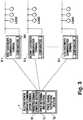
- each of the customer's communication terminals C1 to Cnreceives a presentation signal, its computing section 101 checks a potential of reduction resulting in a reduction factor considering the load reduction request time and the incentive payment. It is now judged whether or not the reduction of the supplied power is possible. If it is possible, the computing section 101 computes the quantity and time period of power to be reduced.
- the potential for reductionincludes event and operation schedule (Xc1), reduction of air conditioner load (Xc2), running time shift in water heater (Xc3), partial stoppage of elevator (Xc4). partial lights-out (Xc5), partial stoppage of computer (Xc6), amount of loss due to partial shutdown of operations in a factory (Xc7) and so on.
- the potential of reduction Xcis computed from the above factors.
Landscapes
- Engineering & Computer Science (AREA)
- Power Engineering (AREA)
- Computer Networks & Wireless Communication (AREA)
- Supply And Distribution Of Alternating Current (AREA)
- Remote Monitoring And Control Of Power-Distribution Networks (AREA)
- Management, Administration, Business Operations System, And Electronic Commerce (AREA)
Abstract
Description
Claims (8)
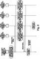
- A power distribution control system comprising acenter communication terminal (S) and a pluralityof customer's communication terminals (C1...Cn) operatively connected to said center communicationterminal (S) through communication linesand to a group of loads,
said center communication terminal (S) comprisingpresentation signal outputting means (S3)for outputting a presentation signal containinga load reduction request time period and an incentivepayment to each of said customer's communicationterminals (C1...Cn) and selectionsignal outputting means (S5) responsive to responsesignals from said customer's communicationterminals (C1...Cn) for outputting a selectionsignal or signals to one or more customer'scommunication terminals (C1...Cn) selected basedon functions including parameters relating tothe recuced quantity of power and reduction timeperiod,
each of said customer's communication terminals(C1...Cn) comprising response signal outputtingmeans (102) for outputting a response signal tosaid center communication terminal (S), saidresponse signal containing the reduced quantityof power and reduction time period which arecomputed from the load reduction request timeperiod, incentive payment contained in the presentationsignal from said center communicationterminal (S), and one or more potential of reduction and power reduction means (103) for reducingthe power supply to the group of loadsfor a given time period, based on the selectionsignal from said center communication terminal(S). - A power distribution control system according toclaim 1, wherein each of the customer's communicationterminals (C1...Cn) has an increased productof the reduced quantity of power times reductiontime period.
- A power distribution control system as definedin claim 1 wherein said selection signal outputtingmeans (S5) of the center communication terminal(S) is adapted to output a selection signalcontaining the reduction time period, reducedquantity of power and incentive paymentwhich are computed from the reduced quantity ofpower and reduction time period in the responsesignal from each of said customer's communicationterminals (C1...Cn).
- A power distributed control system as defined inclaim 2 wherein said selection signal outputtingmeans (S5) of the center communication terminal(S) is adapted to output a selection signal containingthe reduction time period, reduced quantityof power and incentive wage which are computedfrom the reduced quantity of power andreduction time period in the response signalfrom each of said customer's communication terminals(C1...Cn).
- A power distribution control system comprising acenter communication terminal (S) and a pluralityof customer's communication terminals(C1...Cn) operatively connected to said centercommunication terminal (S) through communicationlines and to a group of loads,
said center communication terminal (S) comprisingpresentation signal outputting means (S3)for outputting a presentation signal containinga load reduction request time period to each ofsaid customer's communication terminals(C1...Cn) and selection signal outputting means(S5) responsive to response signals from saidcustomer's communication terminals (C1...Cn) foroutputting a selection signal or signals to oneor more customer's communication terminals(C1...Cn) each of which has a reduced incentivepayment,
each of said customer's communication terminals(C1...Cn) comprising response signal outputtingmeans (102)) for outputting a response signal tosaid center communication terminal (S), saidresponse signal containing an incentive paymentcomputed from a load reduction request time periodcontained in the presentation signal and aplurality of reduction potentials, and powerreduction means (103) for reducing the powersupply to the group of loads for a given timeperiod, based on the selection signal from saidcenter communication terminal (S). - A power distribution control system comprising acenter communication terminal (S) and a pluralityof customer's communication terminals(C1...Cn) operatively connected to said centercommunication terminal (S) through communicationlines and to a group of loads,
said center communication terminal (S) comprisingpresentation signal outputting means (S3)for outputting a presentation signal containinga load reduction request time period and selectionsignal outputting means (S5) responsive toresponse signals from said customer's communicationterminals (C1...Cn) for outputting a selectionsignal or signals to one or more customer'scommunication terminals (C1...Cn) selected basedon functions including parameters relating tothe reduced quantity of power, reduction timeperiod and incentive payment,
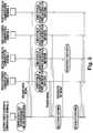
each of said customer's communication terminals(C1...Cn) comprising response signal outputtingmeans (102) for outputting means (102) for outputtinga response signal to said center communicationterminal (S), said response signal containingthe reduced quantity of power, reductiontime period and incentive payment which are computedfrom the load reduction request time periodcontained in the presentation signal fromsaid center communication terminal (S), and oneor more reduction potential and power reductionmeans (103) for reducing the power supply to thegroup of loads for a given time period, based onthe selection signal from said center communicationterminal (S). - A power distribution control system comprising acenter communication terminal (T) and a pluralityof customer's communication terminals(D1...Dn) operatively connected to said centercommunication terminal (T) through communicationlines and to a group of loads,
said center communication terminal (T) comprisingpredicted demand computing means (S1) forcomputing a predicted demand from a demand predictingpotential, price determining means (T1)for comparing said predicted demand with a powersupply capacity to determine an electric powerprice and price signal outputting means (T2) foroutputting a power price signal containing thedetermined power price to each of said customer'scommunication terminals (D1...Dn). - A power distribution control system as definedin any of claims 1 to 6 wherein said center communicationterminal (T) further comprises predicteddemand computing means (S1) for computinga predicted demand from a demand predicting potential,price determining means (T1) for comparingsaid predicted demand with a power supplycapacity to determine an electric power price,and price signal outputting means (T2) for outputtinga power price signal containing the determinedpower price to each of said customer'scommunication terminals (C1...Cn).
Applications Claiming Priority (7)
| Application Number | Priority Date | Filing Date | Title |
|---|---|---|---|
| JP4051941AJPH05260658A (en) | 1992-03-10 | 1992-03-10 | Demand controller |
| JP51941/92 | 1992-03-10 | ||
| JP5194192 | 1992-03-10 | ||
| JP07463492AJP3362055B2 (en) | 1992-03-30 | 1992-03-30 | Power distribution control system |
| JP7463492 | 1992-03-30 | ||
| JP74634/92 | 1992-03-30 | ||
| EP19930103755EP0561255B1 (en) | 1992-03-10 | 1993-03-09 | Demand control apparatus and power distribution control system |
Related Parent Applications (1)
| Application Number | Title | Priority Date | Filing Date |
|---|---|---|---|
| EP19930103755DivisionEP0561255B1 (en) | 1992-03-10 | 1993-03-09 | Demand control apparatus and power distribution control system |
Publications (2)
| Publication Number | Publication Date |
|---|---|
| EP0886362A1true EP0886362A1 (en) | 1998-12-23 |
| EP0886362B1 EP0886362B1 (en) | 2004-08-18 |
Family
ID=26392529
Family Applications (3)
| Application Number | Title | Priority Date | Filing Date |
|---|---|---|---|
| EP19930103755Expired - LifetimeEP0561255B1 (en) | 1992-03-10 | 1993-03-09 | Demand control apparatus and power distribution control system |
| EP20030009607Expired - LifetimeEP1330007B1 (en) | 1992-03-10 | 1993-03-09 | Demand control apparatus and power distribution control system |
| EP19980114424Expired - LifetimeEP0886362B1 (en) | 1992-03-10 | 1993-03-09 | Power distribution control system |
Family Applications Before (2)
| Application Number | Title | Priority Date | Filing Date |
|---|---|---|---|
| EP19930103755Expired - LifetimeEP0561255B1 (en) | 1992-03-10 | 1993-03-09 | Demand control apparatus and power distribution control system |
| EP20030009607Expired - LifetimeEP1330007B1 (en) | 1992-03-10 | 1993-03-09 | Demand control apparatus and power distribution control system |
Country Status (3)
| Country | Link |
|---|---|
| US (1) | US5481140A (en) |
| EP (3) | EP0561255B1 (en) |
| DE (2) | DE69333392T2 (en) |
Cited By (7)
| Publication number | Priority date | Publication date | Assignee | Title |
|---|---|---|---|---|
| WO2001006612A1 (en)* | 1999-07-16 | 2001-01-25 | Perot Systems Corporation | System and method for energy management |
| EP1294071A2 (en) | 2001-09-17 | 2003-03-19 | Mitsubishi Denki Kabushiki Kaisha | Electric power demand adjusting system |
| US6785592B1 (en) | 1999-07-16 | 2004-08-31 | Perot Systems Corporation | System and method for energy management |
| EP1184951A3 (en)* | 2000-08-10 | 2004-12-01 | ABB PATENT GmbH | Method and system for controlling a power supply to electric loads |
| GB2482426A (en)* | 2010-07-27 | 2012-02-01 | Responsiveload Ltd | Responsive load system with aggregation of data |
| GB2482425A (en)* | 2010-07-27 | 2012-02-01 | Responsiveload Ltd | Responsive load system with communication arrangement |
| US8504463B2 (en) | 1997-02-24 | 2013-08-06 | Geophonic Networks, Inc. | Bidding for energy supply |
Families Citing this family (125)
| Publication number | Priority date | Publication date | Assignee | Title |
|---|---|---|---|---|
| US6933627B2 (en) | 1991-01-08 | 2005-08-23 | Nextek Power Systems Inc. | High efficiency lighting system |
| US5969435A (en)* | 1991-01-08 | 1999-10-19 | Nextek Power Systems, Inc. | Modular DC cogenerator systems |
| US5500561A (en)* | 1991-01-08 | 1996-03-19 | Wilhelm; William G. | Customer side power management system and method |
| US5803754A (en)* | 1991-01-08 | 1998-09-08 | Nextek Power Systems Inc. | Modified receptacle and plug for low voltage DC distribution |
| GB2278207B (en)* | 1993-05-17 | 1996-05-15 | Ea Tech Ltd | Heating control apparatus |
| CA2115717A1 (en)* | 1994-02-15 | 1995-08-16 | Nazir Dosani | Method and apparatus for remote control of an electrical load |
| AU3172795A (en)* | 1994-09-19 | 1996-04-04 | Boundary Technologies Pty. Ltd. | Management of an elecrical power supply system by remote deactivation of loads |
| TW300314B (en)* | 1995-06-08 | 1997-03-11 | Tokyo Electron Co Ltd | |
| US20010018971A1 (en)* | 1996-01-10 | 2001-09-06 | Ellen Marcie Emas | Heat storage air conditioning apparatus and heat storage estimating method |
| ITTO980134A1 (en)* | 1998-02-20 | 1999-08-20 | Merloni Elettrodomestici Spa | SYSTEM, DEVICE AND METHOD FOR MONITORING A PLURALITY OF ELECTRIC UTILITIES, IN PARTICULAR HOUSEHOLD APPLIANCES, CONNECTED TO THE NETWORK |
| DE19817191C2 (en)* | 1998-04-17 | 2001-07-05 | Thomas Frank | Method for regulating the overall performance of energy systems, in particular a group of electrical consumers |
| US6529839B1 (en)* | 1998-05-28 | 2003-03-04 | Retx.Com, Inc. | Energy coordination system |
| IT1308762B1 (en)* | 1999-06-28 | 2002-01-10 | Merloni Elettrodomestici Spa | METHOD OF MANAGEMENT OF ENERGY CONSUMPTION BY HOUSEHOLD APPLIANCES. |
| US20040024483A1 (en)* | 1999-12-23 | 2004-02-05 | Holcombe Bradford L. | Controlling utility consumption |
| US6348777B1 (en) | 2000-02-29 | 2002-02-19 | Alaris Medical Systems, Inc. | Power management system |
| JP2001258175A (en)* | 2000-03-14 | 2001-09-21 | Hitachi Ltd | System and method for using secondary battery for power storage |
| JP2002015036A (en)* | 2000-06-28 | 2002-01-18 | Mitsubishi Electric Corp | Power amount control method and power amount control device |
| IT1320622B1 (en)* | 2000-09-05 | 2003-12-10 | Wrap Spa | SYSTEM AND DEVICE FOR THE MONITORING OF AT LEAST ONE ELECTRIC HOUSEHOLD, IN PARTICULAR A HOUSEHOLD APPLIANCE. |
| JP2002269470A (en)* | 2001-03-09 | 2002-09-20 | Hitachi Ltd | Consumer information disclosure and contract method for distributed power generation business |
| US6826029B2 (en)* | 2001-08-30 | 2004-11-30 | The Boeing Company | Methods and apparatus for distributing electrical power |
| US6631622B1 (en) | 2002-03-22 | 2003-10-14 | Whirlpool Corporation | Demand side management of freezer systems |
| JP2003289664A (en)* | 2002-03-28 | 2003-10-10 | Tdk Corp | Control circuit for switching power supply unit and switching power supply unit therewith |
| EP1367685A1 (en)* | 2002-05-31 | 2003-12-03 | Whirlpool Corporation | Electronic system for power consumption management of appliances |
| US7561977B2 (en)* | 2002-06-13 | 2009-07-14 | Whirlpool Corporation | Total home energy management system |
| US7196433B2 (en)* | 2002-08-08 | 2007-03-27 | Tai-Her Yang | Multi-output device with preset power supply priority |
| US20040083112A1 (en)* | 2002-10-25 | 2004-04-29 | Horst Gale R. | Method and apparatus for managing resources of utility providers |
| US7049798B2 (en)* | 2002-11-13 | 2006-05-23 | Power-One, Inc. | System and method for communicating with a voltage regulator |
| US6949916B2 (en) | 2002-11-12 | 2005-09-27 | Power-One Limited | System and method for controlling a point-of-load regulator |
| US7394445B2 (en)* | 2002-11-12 | 2008-07-01 | Power-One, Inc. | Digital power manager for controlling and monitoring an array of point-of-load regulators |
| US7000125B2 (en)* | 2002-12-21 | 2006-02-14 | Power-One, Inc. | Method and system for controlling and monitoring an array of point-of-load regulators |
| US7456617B2 (en)* | 2002-11-13 | 2008-11-25 | Power-One, Inc. | System for controlling and monitoring an array of point-of-load regulators by a host |
| US6833691B2 (en)* | 2002-11-19 | 2004-12-21 | Power-One Limited | System and method for providing digital pulse width modulation |
| US6858797B2 (en)* | 2002-11-22 | 2005-02-22 | Gore Enterprise Holdings, Inc. | Support member for an assembly |
| US7743266B2 (en)* | 2002-12-21 | 2010-06-22 | Power-One, Inc. | Method and system for optimizing filter compensation coefficients for a digital power control system |
| US6933709B2 (en)* | 2003-02-10 | 2005-08-23 | Power-One Limited | Digital control system and method for switched mode power supply |
| US7882372B2 (en)* | 2002-12-21 | 2011-02-01 | Power-One, Inc. | Method and system for controlling and monitoring an array of point-of-load regulators |
| US7673157B2 (en) | 2002-12-21 | 2010-03-02 | Power-One, Inc. | Method and system for controlling a mixed array of point-of-load regulators through a bus translator |
| US7266709B2 (en) | 2002-12-21 | 2007-09-04 | Power-One, Inc. | Method and system for controlling an array of point-of-load regulators and auxiliary devices |
| US7836322B2 (en)* | 2002-12-21 | 2010-11-16 | Power-One, Inc. | System for controlling an array of point-of-load regulators and auxiliary devices |
| US7249267B2 (en)* | 2002-12-21 | 2007-07-24 | Power-One, Inc. | Method and system for communicating filter compensation coefficients for a digital power control system |
| US7737961B2 (en)* | 2002-12-21 | 2010-06-15 | Power-One, Inc. | Method and system for controlling and monitoring an array of point-of-load regulators |
| US7373527B2 (en)* | 2002-12-23 | 2008-05-13 | Power-One, Inc. | System and method for interleaving point-of-load regulators |
| EP1441430B1 (en)* | 2003-01-21 | 2015-05-06 | Whirlpool Corporation | A process for managing and curtailing power demand of appliances and components thereof, and system using such process |
| US7710092B2 (en)* | 2003-02-10 | 2010-05-04 | Power-One, Inc. | Self tracking ADC for digital power supply control systems |
| US7023190B2 (en)* | 2003-02-10 | 2006-04-04 | Power-One, Inc. | ADC transfer function providing improved dynamic regulation in a switched mode power supply |
| US6936999B2 (en)* | 2003-03-14 | 2005-08-30 | Power-One Limited | System and method for controlling output-timing parameters of power converters |
| US7080265B2 (en)* | 2003-03-14 | 2006-07-18 | Power-One, Inc. | Voltage set point control scheme |
| US6788036B1 (en) | 2003-03-28 | 2004-09-07 | Ower-One Limited | Method and system for current sharing among a plurality of power modules |
| US20040230533A1 (en)* | 2003-05-16 | 2004-11-18 | Benco David S. | Pro-rated consumable resource governor |
| US20050027636A1 (en)* | 2003-07-29 | 2005-02-03 | Joel Gilbert | Method and apparatus for trading energy commitments |
| US7854129B2 (en)* | 2003-10-15 | 2010-12-21 | Ice Energy, Inc. | Refrigeration apparatus |
| US8234876B2 (en)* | 2003-10-15 | 2012-08-07 | Ice Energy, Inc. | Utility managed virtual power plant utilizing aggregated thermal energy storage |
| EP1533893A3 (en)* | 2003-11-19 | 2014-07-02 | Panasonic Corporation | Generator control system, generating apparatus control method, program and record medium |
| US6958592B2 (en)* | 2003-11-26 | 2005-10-25 | Power-One, Inc. | Adaptive delay control circuit for switched mode power supply |
| US7372682B2 (en)* | 2004-02-12 | 2008-05-13 | Power-One, Inc. | System and method for managing fault in a power system |
| US20050286709A1 (en)* | 2004-06-28 | 2005-12-29 | Steve Horton | Customer service marketing |
| US20060049694A1 (en)* | 2004-09-03 | 2006-03-09 | Lawrence Kates | Method and apparatus for load management in an electric power system |
| US20060052906A1 (en)* | 2004-09-03 | 2006-03-09 | Lawrence Kates | Method and apparatus for load management metering in an electric power system |
| US7554310B2 (en)* | 2005-03-18 | 2009-06-30 | Power-One, Inc. | Digital double-loop output voltage regulation |
| US7141956B2 (en)* | 2005-03-18 | 2006-11-28 | Power-One, Inc. | Digital output voltage regulation circuit having first control loop for high speed and second control loop for high accuracy |
| US7239115B2 (en)* | 2005-04-04 | 2007-07-03 | Power-One, Inc. | Digital pulse width modulation controller with preset filter coefficients |
| US7327149B2 (en)* | 2005-05-10 | 2008-02-05 | Power-One, Inc. | Bi-directional MOS current sense circuit |
| US8615332B2 (en)* | 2005-06-09 | 2013-12-24 | Whirlpool Corporation | Smart current attenuator for energy conservation in appliances |
| US8027752B2 (en)* | 2005-06-09 | 2011-09-27 | Whirlpool Corporation | Network for changing resource consumption in an appliance |
| US9310098B2 (en) | 2006-01-27 | 2016-04-12 | Emerson Electric Co. | Water heater control using external temperature sensor |
| US9188363B2 (en) | 2006-01-27 | 2015-11-17 | Emerson Electric Co. | Smart energy controlled water heater |
| US9151516B2 (en)* | 2006-01-27 | 2015-10-06 | Emerson Electric Co. | Smart energy controlled water heater |
| JP2007236038A (en)* | 2006-02-28 | 2007-09-13 | Sanyo Electric Co Ltd | Demand controller |
| US20070299562A1 (en)* | 2006-06-26 | 2007-12-27 | Lawrence Kates | Method and apparatus for temperature-based load management metering in an electric power system |
| JP4201050B2 (en)* | 2006-10-11 | 2008-12-24 | トヨタ自動車株式会社 | Electric load control device, electric load control method, electric load control device, and electric load control method |
| US7705484B2 (en)* | 2007-04-10 | 2010-04-27 | Whirlpool Corporation | Energy management system and method |
| US20110182094A1 (en)* | 2007-08-13 | 2011-07-28 | The Powerwise Group, Inc. | System and method to manage power usage |
| US8619443B2 (en) | 2010-09-29 | 2013-12-31 | The Powerwise Group, Inc. | System and method to boost voltage |
| US8085009B2 (en) | 2007-08-13 | 2011-12-27 | The Powerwise Group, Inc. | IGBT/FET-based energy savings device for reducing a predetermined amount of voltage using pulse width modulation |
| US8085010B2 (en)* | 2007-08-24 | 2011-12-27 | The Powerwise Group, Inc. | TRIAC/SCR-based energy savings device for reducing a predetermined amount of voltage using pulse width modulation |
| US8120307B2 (en) | 2007-08-24 | 2012-02-21 | The Powerwise Group, Inc. | System and method for providing constant loading in AC power applications |
| US8698447B2 (en) | 2007-09-14 | 2014-04-15 | The Powerwise Group, Inc. | Energy saving system and method for devices with rotating or reciprocating masses |
| US8810190B2 (en)* | 2007-09-14 | 2014-08-19 | The Powerwise Group, Inc. | Motor controller system and method for maximizing energy savings |
| US8160752B2 (en) | 2008-09-30 | 2012-04-17 | Zome Networks, Inc. | Managing energy usage |
| US7834613B2 (en)* | 2007-10-30 | 2010-11-16 | Power-One, Inc. | Isolated current to voltage, voltage to voltage converter |
| US8014902B2 (en) | 2008-02-22 | 2011-09-06 | Lawrence Kates | Method and apparatus for energy-efficient temperature-based systems management |
| US20100010683A1 (en)* | 2008-07-14 | 2010-01-14 | Lawrence Kates | Method and apparatus for power-limiting electrical access |
| US8004255B2 (en)* | 2008-08-07 | 2011-08-23 | The Powerwise Group, Inc. | Power supply for IGBT/FET drivers |
| US9303878B2 (en) | 2008-09-15 | 2016-04-05 | General Electric Company | Hybrid range and method of use thereof |
| US8843242B2 (en)* | 2008-09-15 | 2014-09-23 | General Electric Company | System and method for minimizing consumer impact during demand responses |
| US8548638B2 (en)* | 2008-09-15 | 2013-10-01 | General Electric Company | Energy management system and method |
| US8803040B2 (en)* | 2008-09-15 | 2014-08-12 | General Electric Company | Load shedding for surface heating units on electromechanically controlled cooking appliances |
| AU2009290591B2 (en)* | 2008-09-15 | 2015-10-01 | Haier Us Appliance Solutions, Inc. | Energy management of clothes washer appliance |
| US8541719B2 (en)* | 2008-09-15 | 2013-09-24 | General Electric Company | System for reduced peak power consumption by a cooking appliance |
| DE102008057563B4 (en) | 2008-11-11 | 2017-07-13 | Fraunhofer-Gesellschaft zur Förderung der angewandten Forschung e.V. | Method and device for network-compliant operation of a plurality of decentralized with consumers / generators of electrical energy and connected to a low-voltage electrical network unit |
| US9665838B2 (en)* | 2008-12-03 | 2017-05-30 | Whirlpool Corporation | Messaging architecture and system for electronic management of resources |
| US20100145884A1 (en)* | 2008-12-04 | 2010-06-10 | American Power Conversion Corporation | Energy savings aggregation |
| US8200370B2 (en) | 2008-12-04 | 2012-06-12 | American Power Conversion Corporation | Energy reduction |
| JP4710982B2 (en)* | 2009-01-26 | 2011-06-29 | ダイキン工業株式会社 | Demand control apparatus, demand control system, and demand control program |
| US20100207728A1 (en)* | 2009-02-18 | 2010-08-19 | General Electric Corporation | Energy management |
| US8271147B2 (en) | 2009-02-26 | 2012-09-18 | Massachusetts Institute Of Technology | Methods and apparatus for energy demand management |
| MX361682B (en) | 2009-09-08 | 2018-12-13 | The Powerwise Group Inc | Energy saving system and method for devices with rotating or reciprocating masses. |
| US8698446B2 (en)* | 2009-09-08 | 2014-04-15 | The Powerwise Group, Inc. | Method to save energy for devices with rotating or reciprocating masses |
| US8943845B2 (en) | 2009-09-15 | 2015-02-03 | General Electric Company | Window air conditioner demand supply management response |
| US8869569B2 (en)* | 2009-09-15 | 2014-10-28 | General Electric Company | Clothes washer demand response with at least one additional spin cycle |
| US8874277B2 (en)* | 2009-09-15 | 2014-10-28 | Denis Kouroussis | Smart-grid adaptive power management method and system with power factor optimization and total harmonic distortion reduction |
| US8522579B2 (en)* | 2009-09-15 | 2013-09-03 | General Electric Company | Clothes washer demand response with dual wattage or auxiliary heater |
| US8943857B2 (en)* | 2009-09-15 | 2015-02-03 | General Electric Company | Clothes washer demand response by duty cycling the heater and/or the mechanical action |
| WO2011052957A2 (en)* | 2009-10-26 | 2011-05-05 | Lg Electronics Inc. | Method of controlling network system |
| GB2469361B (en)* | 2010-01-28 | 2011-04-13 | Energy2Trade Ltd | Power flow measurement and management |
| US8386087B2 (en)* | 2010-08-02 | 2013-02-26 | General Electric Company | Load shed system for demand response without AMI/AMR system |
| US8801862B2 (en) | 2010-09-27 | 2014-08-12 | General Electric Company | Dishwasher auto hot start and DSM |
| JP5487125B2 (en)* | 2011-01-11 | 2014-05-07 | 株式会社東芝 | Power supply / demand adjustment reserve capacity trading system and power supply / demand adjustment reserve capacity transaction method |
| US20120179596A1 (en)* | 2011-01-11 | 2012-07-12 | Kenji Mitsumoto | Power reserve margin trading system and power reserve margin trading method |
| US9300138B2 (en)* | 2011-06-07 | 2016-03-29 | Fujitsu Limited | System and method for managing power consumption |
| US20130066482A1 (en)* | 2011-09-13 | 2013-03-14 | Samsung Electronics Co., Ltd. | Apparatus and method for executing energy demand response process in an electrical power network |
| IN2014DN07294A (en)* | 2012-03-07 | 2015-04-24 | Felica Networks Inc | |
| CA2774407C (en) | 2012-04-17 | 2013-06-25 | Renewable Environmental Energy Services Inc. | Rate based power management device |
| JP5901758B2 (en) | 2012-05-28 | 2016-04-13 | 三菱電機株式会社 | Supply and demand adjustment system |
| JP6012313B2 (en)* | 2012-07-11 | 2016-10-25 | 京セラ株式会社 | Power control apparatus, power control method, and power control system |
| US20140246909A1 (en)* | 2013-03-04 | 2014-09-04 | Adam A. Todorski | System and method for balancing supply and demand of energy on an electrical grid |
| US9405304B2 (en) | 2013-03-15 | 2016-08-02 | A. O. Smith Corporation | Water heater and method of operating a water heater |
| JP2014207793A (en)* | 2013-04-15 | 2014-10-30 | 株式会社東芝 | Request control device, method, and program |
| JP6342131B2 (en) | 2013-09-13 | 2018-06-13 | 株式会社東芝 | Received energy reduction information calculation device, received energy reduction information calculation method, and program |
| CN104536311B (en)* | 2014-12-02 | 2016-03-23 | 漳州科华技术有限责任公司 | A kind of UPS multiple-channel output intelligent control system and method |
| US9991738B2 (en)* | 2015-01-07 | 2018-06-05 | Gojo Industries, Inc. | Powering a plurality of dispensers |
| DE102016112249A1 (en)* | 2016-07-05 | 2018-01-11 | Dr. Ing. H.C. F. Porsche Aktiengesellschaft | Method for distributing energy in a home energy supply system |
| US10971949B2 (en)* | 2016-12-31 | 2021-04-06 | Abb Schweiz Ag | Systems and methods for performing building energy management |
| CN107395397B (en)* | 2017-06-23 | 2020-09-04 | 深圳市盛路物联通讯技术有限公司 | Power consumption control method and device based on Internet of things |
| CN108306293B (en)* | 2018-01-18 | 2020-12-15 | 浙江日业电力科技有限公司 | Low-voltage electric energy quality control device |
Citations (3)
| Publication number | Priority date | Publication date | Assignee | Title |
|---|---|---|---|---|
| EP0265342A2 (en)* | 1986-10-24 | 1988-04-27 | Sangamo Weston, Inc. | Distribution energy management system |
| WO1989012342A1 (en)* | 1986-11-24 | 1989-12-14 | Peter Niedner | Process and system for reducing power peaks of supply and/or consumption of power transmitted through lines |
| EP0445448A1 (en)* | 1990-03-06 | 1991-09-11 | Mitsubishi Denki Kabushiki Kaisha | Control and supervisory system for power distribution equipment |
Family Cites Families (9)
| Publication number | Priority date | Publication date | Assignee | Title |
|---|---|---|---|---|
| US4161028A (en)* | 1978-05-30 | 1979-07-10 | Leeds & Northrup Company | Electric demand control system |
| GB2043371B (en)* | 1979-02-21 | 1983-05-25 | South Eastern Elec Board | Load shedding |
| US4283635A (en)* | 1979-07-25 | 1981-08-11 | Honeywell Inc. | Load demand control system |
| US4464724A (en)* | 1981-06-17 | 1984-08-07 | Cyborex Laboratories, Inc. | System and method for optimizing power shed/restore operations |
| US4694192A (en)* | 1984-11-23 | 1987-09-15 | Honeywell Inc. | Simplified demand limit control |
| FR2584542B1 (en)* | 1985-07-05 | 1987-10-23 | Cahors App Elec | POWER ADAPTER FOR ELECTRICAL INSTALLATIONS, ESPECIALLY DOMESTIC |
| US4731547A (en)* | 1986-12-12 | 1988-03-15 | Caterpillar Inc. | Peak power shaving apparatus and method |
| US4916328A (en)* | 1988-12-08 | 1990-04-10 | Honeywell Inc. | Add/shed load control using anticipatory processes |
| DE4019523A1 (en)* | 1990-06-19 | 1992-01-09 | Decher Dieter | ARRANGEMENT FOR CONTROLLING THE POWER CONSUMPTION OF A CUSTOMER |
- 1993
- 1993-03-04USUS08/026,552patent/US5481140A/ennot_activeExpired - Fee Related
- 1993-03-09DEDE1993633392patent/DE69333392T2/ennot_activeExpired - Lifetime
- 1993-03-09DEDE1993633596patent/DE69333596T2/ennot_activeExpired - Lifetime
- 1993-03-09EPEP19930103755patent/EP0561255B1/ennot_activeExpired - Lifetime
- 1993-03-09EPEP20030009607patent/EP1330007B1/ennot_activeExpired - Lifetime
- 1993-03-09EPEP19980114424patent/EP0886362B1/ennot_activeExpired - Lifetime
Patent Citations (3)
| Publication number | Priority date | Publication date | Assignee | Title |
|---|---|---|---|---|
| EP0265342A2 (en)* | 1986-10-24 | 1988-04-27 | Sangamo Weston, Inc. | Distribution energy management system |
| WO1989012342A1 (en)* | 1986-11-24 | 1989-12-14 | Peter Niedner | Process and system for reducing power peaks of supply and/or consumption of power transmitted through lines |
| EP0445448A1 (en)* | 1990-03-06 | 1991-09-11 | Mitsubishi Denki Kabushiki Kaisha | Control and supervisory system for power distribution equipment |
Cited By (11)
| Publication number | Priority date | Publication date | Assignee | Title |
|---|---|---|---|---|
| US8504463B2 (en) | 1997-02-24 | 2013-08-06 | Geophonic Networks, Inc. | Bidding for energy supply |
| US8527389B2 (en) | 1997-02-24 | 2013-09-03 | Geophonic Networks, Inc. | Bidding for energy supply to resellers and their customers |
| WO2001006612A1 (en)* | 1999-07-16 | 2001-01-25 | Perot Systems Corporation | System and method for energy management |
| US6785592B1 (en) | 1999-07-16 | 2004-08-31 | Perot Systems Corporation | System and method for energy management |
| EP1184951A3 (en)* | 2000-08-10 | 2004-12-01 | ABB PATENT GmbH | Method and system for controlling a power supply to electric loads |
| EP1294071A2 (en) | 2001-09-17 | 2003-03-19 | Mitsubishi Denki Kabushiki Kaisha | Electric power demand adjusting system |
| EP1294071A3 (en)* | 2001-09-17 | 2008-04-02 | Mitsubishi Denki Kabushiki Kaisha | Electric power demand adjusting system |
| GB2482426A (en)* | 2010-07-27 | 2012-02-01 | Responsiveload Ltd | Responsive load system with aggregation of data |
| GB2482425A (en)* | 2010-07-27 | 2012-02-01 | Responsiveload Ltd | Responsive load system with communication arrangement |
| GB2482426B (en)* | 2010-07-27 | 2013-03-27 | Responsiveload Ltd | Responsive load monitoring system and method |
| GB2482425B (en)* | 2010-07-27 | 2013-03-27 | Responsiveload Ltd | Responsive load monitoring system and method |
Also Published As
| Publication number | Publication date |
|---|---|
| DE69333392D1 (en) | 2004-02-26 |
| HK1017167A1 (en) | 1999-11-12 |
| EP1330007B1 (en) | 2012-08-22 |
| HK1011468A1 (en) | 1999-07-09 |
| EP0886362B1 (en) | 2004-08-18 |
| DE69333596D1 (en) | 2004-09-23 |
| US5481140A (en) | 1996-01-02 |
| EP1330007A3 (en) | 2005-11-30 |
| EP1330007A2 (en) | 2003-07-23 |
| DE69333392T2 (en) | 2004-11-11 |
| EP0561255B1 (en) | 2004-01-21 |
| EP0561255A1 (en) | 1993-09-22 |
| HK1057293A1 (en) | 2004-03-19 |
| DE69333596T2 (en) | 2005-09-15 |
Similar Documents
| Publication | Publication Date | Title |
|---|---|---|
| EP0886362A1 (en) | Power distribution control system | |
| US8041467B2 (en) | Optimal dispatch of demand side electricity resources | |
| US8880231B2 (en) | Enterprise energy automation | |
| US4336462A (en) | Electrical load restoration system | |
| US10447035B2 (en) | Electric power creation control system and method | |
| US8521336B2 (en) | Energy reduction | |
| Sanghvi | Economic costs of electricity supply interruptions: US and foreign experience | |
| Albadi et al. | Demand response in electricity markets: An overview | |
| US8897923B2 (en) | Achieving energy demand response using price signals and a load control transponder | |
| US20190035035A1 (en) | Power system | |
| US7711655B2 (en) | Electric power trading support system | |
| US5675503A (en) | Adaptive load cycler for controlled reduction of energy use | |
| AU2009322857B2 (en) | Energy reduction | |
| US20100145884A1 (en) | Energy savings aggregation | |
| US20090024545A1 (en) | Method and system for measurement and control of individual circuits | |
| JP2002123578A (en) | Electric power retail system | |
| JP3362055B2 (en) | Power distribution control system | |
| AU2020277159A1 (en) | System and method for increasing appliance control in an electricity grid | |
| HK1017167B (en) | Power distribution control system | |
| JP2003235158A (en) | Energy supply management system, energy supply management method, and program | |
| HK1057293B (en) | Demand control apparatus and power distribution control system | |
| JP3756443B2 (en) | Power generation control device for power consignment | |
| JP2002044864A (en) | Power supply method and power supply service system | |
| Andersson et al. | Cost-effective incentives for cooperation between participants in the electricity market | |
| Geiss | Pricing residential load shedding as a call option |
Legal Events
| Date | Code | Title | Description |
|---|---|---|---|
| PUAI | Public reference made under article 153(3) epc to a published international application that has entered the european phase | Free format text:ORIGINAL CODE: 0009012 | |
| 17P | Request for examination filed | Effective date:19980731 | |
| AC | Divisional application: reference to earlier application | Ref document number:561255 Country of ref document:EP | |
| AK | Designated contracting states | Kind code of ref document:A1 Designated state(s):DE FR GB | |
| 17Q | First examination report despatched | Effective date:20030703 | |
| GRAP | Despatch of communication of intention to grant a patent | Free format text:ORIGINAL CODE: EPIDOSNIGR1 | |
| GRAS | Grant fee paid | Free format text:ORIGINAL CODE: EPIDOSNIGR3 | |
| GRAA | (expected) grant | Free format text:ORIGINAL CODE: 0009210 | |
| AC | Divisional application: reference to earlier application | Ref document number:0561255 Country of ref document:EP Kind code of ref document:P | |
| AK | Designated contracting states | Kind code of ref document:B1 Designated state(s):DE FR GB | |
| REG | Reference to a national code | Ref country code:GB Ref legal event code:FG4D | |
| REF | Corresponds to: | Ref document number:69333596 Country of ref document:DE Date of ref document:20040923 Kind code of ref document:P | |
| ET | Fr: translation filed | ||
| REG | Reference to a national code | Ref country code:HK Ref legal event code:GR Ref document number:1017167 Country of ref document:HK | |
| PLBE | No opposition filed within time limit | Free format text:ORIGINAL CODE: 0009261 | |
| STAA | Information on the status of an ep patent application or granted ep patent | Free format text:STATUS: NO OPPOSITION FILED WITHIN TIME LIMIT | |
| 26N | No opposition filed | Effective date:20050519 | |
| REG | Reference to a national code | Ref country code:GB Ref legal event code:746 Effective date:20090330 | |
| PGFP | Annual fee paid to national office [announced via postgrant information from national office to epo] | Ref country code:FR Payment date:20120319 Year of fee payment:20 | |
| PGFP | Annual fee paid to national office [announced via postgrant information from national office to epo] | Ref country code:GB Payment date:20120307 Year of fee payment:20 | |
| PGFP | Annual fee paid to national office [announced via postgrant information from national office to epo] | Ref country code:DE Payment date:20120411 Year of fee payment:20 | |
| REG | Reference to a national code | Ref country code:DE Ref legal event code:R071 Ref document number:69333596 Country of ref document:DE | |
| REG | Reference to a national code | Ref country code:GB Ref legal event code:PE20 Expiry date:20130308 | |
| PG25 | Lapsed in a contracting state [announced via postgrant information from national office to epo] | Ref country code:GB Free format text:LAPSE BECAUSE OF EXPIRATION OF PROTECTION Effective date:20130308 Ref country code:DE Free format text:LAPSE BECAUSE OF EXPIRATION OF PROTECTION Effective date:20130312 |