EP0885598A2 - A receiving part for a retaining component of a vertebral column implant - Google Patents
A receiving part for a retaining component of a vertebral column implantDownload PDFInfo
- Publication number
- EP0885598A2 EP0885598A2EP98109152AEP98109152AEP0885598A2EP 0885598 A2EP0885598 A2EP 0885598A2EP 98109152 AEP98109152 AEP 98109152AEP 98109152 AEP98109152 AEP 98109152AEP 0885598 A2EP0885598 A2EP 0885598A2
- Authority
- EP
- European Patent Office
- Prior art keywords
- receiving part
- fork
- head
- part according
- shank
- Prior art date
- Legal status (The legal status is an assumption and is not a legal conclusion. Google has not performed a legal analysis and makes no representation as to the accuracy of the status listed.)
- Granted
Links
- 239000007943implantSubstances0.000titleclaimsabstractdescription8
- 241001125879GobioSpecies0.000description8
- 230000015572biosynthetic processEffects0.000description6
- 238000005452bendingMethods0.000description4
- 230000000295complement effectEffects0.000description2
- 230000000694effectsEffects0.000description2
- 230000004048modificationEffects0.000description2
- 238000012986modificationMethods0.000description2
- 230000006835compressionEffects0.000description1
- 238000007906compressionMethods0.000description1
- 230000001010compromised effectEffects0.000description1
Images

Classifications
- A—HUMAN NECESSITIES
- A61—MEDICAL OR VETERINARY SCIENCE; HYGIENE
- A61B—DIAGNOSIS; SURGERY; IDENTIFICATION
- A61B17/00—Surgical instruments, devices or methods
- A61B17/56—Surgical instruments or methods for treatment of bones or joints; Devices specially adapted therefor
- A61B17/58—Surgical instruments or methods for treatment of bones or joints; Devices specially adapted therefor for osteosynthesis, e.g. bone plates, screws or setting implements
- A61B17/68—Internal fixation devices, including fasteners and spinal fixators, even if a part thereof projects from the skin
- A61B17/70—Spinal positioners or stabilisers, e.g. stabilisers comprising fluid filler in an implant
- A61B17/7001—Screws or hooks combined with longitudinal elements which do not contact vertebrae
- A61B17/7035—Screws or hooks, wherein a rod-clamping part and a bone-anchoring part can pivot relative to each other
- A61B17/7037—Screws or hooks, wherein a rod-clamping part and a bone-anchoring part can pivot relative to each other wherein pivoting is blocked when the rod is clamped
- A—HUMAN NECESSITIES
- A61—MEDICAL OR VETERINARY SCIENCE; HYGIENE
- A61B—DIAGNOSIS; SURGERY; IDENTIFICATION
- A61B17/00—Surgical instruments, devices or methods
- A61B17/56—Surgical instruments or methods for treatment of bones or joints; Devices specially adapted therefor
- A61B17/58—Surgical instruments or methods for treatment of bones or joints; Devices specially adapted therefor for osteosynthesis, e.g. bone plates, screws or setting implements
- A61B17/68—Internal fixation devices, including fasteners and spinal fixators, even if a part thereof projects from the skin
- A61B17/70—Spinal positioners or stabilisers, e.g. stabilisers comprising fluid filler in an implant
- A61B17/7001—Screws or hooks combined with longitudinal elements which do not contact vertebrae
- A61B17/7032—Screws or hooks with U-shaped head or back through which longitudinal rods pass
- A—HUMAN NECESSITIES
- A61—MEDICAL OR VETERINARY SCIENCE; HYGIENE
- A61F—FILTERS IMPLANTABLE INTO BLOOD VESSELS; PROSTHESES; DEVICES PROVIDING PATENCY TO, OR PREVENTING COLLAPSING OF, TUBULAR STRUCTURES OF THE BODY, e.g. STENTS; ORTHOPAEDIC, NURSING OR CONTRACEPTIVE DEVICES; FOMENTATION; TREATMENT OR PROTECTION OF EYES OR EARS; BANDAGES, DRESSINGS OR ABSORBENT PADS; FIRST-AID KITS
- A61F2/00—Filters implantable into blood vessels; Prostheses, i.e. artificial substitutes or replacements for parts of the body; Appliances for connecting them with the body; Devices providing patency to, or preventing collapsing of, tubular structures of the body, e.g. stents
- A61F2/02—Prostheses implantable into the body
- A61F2/30—Joints
- A61F2/44—Joints for the spine, e.g. vertebrae, spinal discs
- A—HUMAN NECESSITIES
- A61—MEDICAL OR VETERINARY SCIENCE; HYGIENE
- A61B—DIAGNOSIS; SURGERY; IDENTIFICATION
- A61B17/00—Surgical instruments, devices or methods
- A61B17/56—Surgical instruments or methods for treatment of bones or joints; Devices specially adapted therefor
- A61B17/58—Surgical instruments or methods for treatment of bones or joints; Devices specially adapted therefor for osteosynthesis, e.g. bone plates, screws or setting implements
- A61B17/68—Internal fixation devices, including fasteners and spinal fixators, even if a part thereof projects from the skin
- A61B17/70—Spinal positioners or stabilisers, e.g. stabilisers comprising fluid filler in an implant
- A61B17/7049—Connectors, not bearing on the vertebrae, for linking longitudinal elements together
Definitions
- the inventionrelates to a receiving part for a retaining component of a vertebral column implant according to the preamble of claim 1.
- retaining componentsthere may serve e.g. so-called pedicle screws which are screwed into the pedicle of the vertebrae.
- the head of the pedicle screwis either annular or fork-shaped.
- annular pedicle screw headse.g. a distraction rod is guided through and is fixed on both sides of the head with the help of a nut.
- fork-shaped headsit is known in the inside to provide threaded sections for a gudgeon with which a previously inserted distraction rod or likewise may be fastened.
- a similar receiving part for a distraction rod or likewiseis also known for hook-like retaining components, for example with so-called lamina hooks or pedicle hooks which are hooked into the corresponding vertebra parts.
- inner threaded sectionsare formed as a saw tooth thread.
- the steep flank of the saw tooth thread of the receiving partis distant to the opening of the fork-shaped section. It is to be understood that the thread of the screw is complementary, i.e. the steep flank is aligned oppositely.
- Such a design of the threadcauses essentially only a tension force on the arm sections of the fork-shaped section when the screw is pressed against the retaining component to be fastened. A bending apart of the tongs or arms does not occur.
- the thread within the receiving partmay be provided at a distance to the free end. In this way it is achieved that the screw cannot be screwed skewly.
- the screw at one endmay have a smooth section in order to simplify the introduction of the screw particularly into the smooth initial section in the receiving part.
- An advantage of the receiving part according to the inventionalso lies in the fact that it may be dimensioned smaller, since the bending forces on account of the fastening of the component with the help of a screw largely do not occur.
- the inventionmay be applied everywhere where, in a fork-shaped section, retaining components of vertebral column implants are to be fastened.
- the retaining componentmay according to one formation of the invention be a rod-like element, preferably a distraction rod.
- the retaining componentmay however also be formed by the shank, whose end near to the head is accommodated in a fork-shaped section. So that such a pedicle screw permits an angular position between the screw shank and the head, one formation of the invention provides that the end of the shank near to the head, which is broadened in diameter, comprises a spherical bearing surface which cooperates with a spherical bearing surface in the fork-shaped head.
- the end surface of the shankis convex, and between the screw and the inner surface there is arranged a disk which on the side facing the end surface may be plane or concave.
- a diskwhich on the side facing the end surface may be plane or concave.
- the curvatures of the end surface of the screw shank and of the facing side of the diskare formed with an approximately equal radius.
- the disk according to a further formation of the inventionmay be plane.
- a screw which cooperates with the fork-shaped head via a saw tooth threadthen presses onto the disk which for its part fastens the shank of the pedicle screw at any angular position. It has been shown that such a design in the head region of the pedicle screw has the result of higher retaining forces so that the once assumed relative position of the shank to the head remains kept even with larger forces.
- a distraction rod or likewisemay be applied via which then the pressing force is transmitted to the disk, wherein the shank for its part is fastened in the head of the pedicle screw.
- the diskmay comprise an outer thread and be screwed into the head of the pedicle screw, wherein of course the inner sides of the recess must be provided with a threaded section. Below this threaded section there may be present a free rotation which reaches the disk when it is completely screwed in, bearing on the crowned surface of the end of the screw shank on the head side.
- the diskmay be provided on the periphery with radial slots so that a better bearing on the spherical end of the pedicle screw is made possible.
- the diskmay further be provided centrally with an opening. Via the opening a tool may engage with the facing end of the shank of the pedicle screw and turn the shank.
- the openingmay be so dimensioned together with the concave surface of the disk, that a rod accommodated by the receiving part bears against the end, near to the head, of the pedicle screw shank when it is pressed with the screw in the receiving part.
- the fork-shaped headWith conventionally parted pedicle screws it is necessary that the head is pushed over the shank before the shank is rotated in. The handling of such a unit is however complicated.
- one formation of the inventionprovides for the fork-shaped head to laterally comprise a slot which is dimensioned such that the broadened end can be laterally introduced into the receiving space of the head. In this manner the shank alone may be screwed into a vertebra. The head may subsequently laterally be put onto the end of the shank, which is near the head.
- the slotweakens the corresponding arm region of the head but since the saw tooth thread, as has been cited several times, prevents a bending apart of the head section, the weaking is tolerable.
- Another formation of the inventionprovides that on the outer side of the arms of the fork-shaped head diametrical recess are formed.
- the recessesserve for accommodating a fork-shaped section which is part of a rotating or tensioning tool. With the help of the tool which can be applied in the recesses, the pedicle screw may be rotated. The tool may also laterally grasp the head so that a simultaneous access from above is still possible. It is to be understood that the recesses may be advantageous also with pedicle screws with a one-piece formed-on head.
- the receiving partaccommodates an annular cage.
- the cagecomprises several slots which are formed by the lower side parallel to the axis. Furthermore on the inside the cage has a spherical concave bearing surface which cooperates with a convex end of the shank of the pedicle screw. On the outer side the cage has a conical surface which cooperates with a complementary conical surface in the receiving part. If a force is exerted on the cage in the direction of the pedicle screw the cage is pressed radially together and by way of this exerts a pressing force onto the spherical surface of the screw shank. This pressure is sufficient in order to obtain a secure fastening of the screw shank relative to the receiving part.
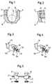
- a receiving part 10with is fork-shaped with arm sections 12, 14.
- the receiving part 10may be the head of a pedicle screw or a section of a hook for an vertebral column implant.
- threaded sections 16, 18With a saw tooth shape. It is essential that the steep flank 20 of the saw tooth thread is distant to the open side of the receiving part 10. From the open side in the corresponding recess of the receiving part 10 a distraction rod may be placed in as is shown dashed at 22.
- a gudgeon 24is to be seen which for its part comprises a saw tooth thread 26 which cooperates with the threaded sections 16, 18.
- the distraction rod 22may be fixed in the receiving part 10 with the help of the gudgeon 24. Due to the shape of the thread on the arm sections 12, 14 with an axial force on the gudgeon 24 essentially a tensional loading is exerted so that by way of this it is prevented that the arm sections 12, 14 are bent apart.
- Fig. 3shows a pedicle hook 28 with a fork-shaped receiving part 10a which comprises threaded sections 16a, 18a in the shape of a saw tooth thread.
- a gudgeon 24a with a hexagon socket 30comprises a corresponding saw tooth thread 26a.
- a lamina hook 32comprises a receiving part 10b with inner threaded sections 16b, 18b for receiving a gudgeon 24b with a saw tooth thread 26b.
- a distraction rodmay be fixed.
- Fig. 5there are shown two hooks 34, 36 which receive rod-like elements 38, 40.
- a distraction rod 42which is channeled or provided with a thread and which bears against the rods 38, 40.
- gudgeons 44 or 46the device shown, which forms a type of bridge, may be fixed.
- the gudgeons 44, 46 or the receiving parts of the hooks 34, 36are in turn provided with a saw tooth thread of the above mentioned type and manner.
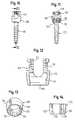
- a pedicle screw 50with a shank 52 and a head 54.
- the head 52comprises a normal thread 54.
- the shank 52is at the end near to the head formed with a broadened section 56 which on the lower side comprises an annular spherical bearing surface 58.
- the end surface of the broadened sectionis shaped spherically convex, as is shown at 60.
- the broadeninghas a hexagon socket 62 for receiving a corresponding rotational tool.
- the head 54is fork-shaped similar to the receiving part 10 and at the end facing the shank 52 is provided with an opening 64 through which the shank 52 extends.
- a part of the walling of the opening 64comprises an annular spherical bearing surface 66 which cooperates with the spherical bearing surface 58.
- the shank 52may therefore assume in a limited spacial angle, any angular position to the head 54.
- a disk 68which on the upper side is plane but on the lower side comprises a concavely curved surface with a curvature which corresponds to the end surface 60 of the shank 52.
- the disk 68is inserted approximately fittingly into the inner space of the end 54 so that it is radially secured.
- the disk 68may be provided with an outer thread, and the inner thread of the head 54 may extend until shortly above the opening 64, 66. In this way the disk 68 may be screwed in until it reaches free rotation and here by way of a corresponding contact pressure can be pressed into engagement with the crowned end of the shank 52.
- the outer thread of the disk 68 and the inner threaded sections in the inside of the head 54are not provided with reference numerals.
- a screw 72is threaded into inner threaded sections of the head 54, wherein the threaded sections again comprise a saw tooth thread, which however here is not shown in detail.
- a shank 74 of the screw 72cooperates with the plane surface of the disk 68 and presses this against the end surface 60 of the shank 52. In this manner the angular position between the head 54 and the shank 52 can be effectively fixed.
- a distraction rodvia which a pressure may be exerted onto the disk 68, wherein the rod for its part may be fixed in its position.
- the shank 74 of the screw 72must be designed correspondingly shorter. It is still to be mentioned that the shank 74 at the lower end is convexly rounded.
- Fig. 7the head of a pedicle screw similar to that according to Fig. 6 is shown, it however has some modifications.
- the headis indicated at 54a.
- the head 54a laterally in the region near the shankcomprises a slot 78, via which the end, near the head, of the shank 52 may be inserted.
- the shank 52firstly can be screwed into a pedicle of a vertebra after which subsequently the head 54a is placed on.
- slots 80, 82for receiving the prongs of a hook-like tool section which laterally grasps the head on the outside in order to exert a tension effect or to rotate the head. It is to be understood that the slots 80, 82 may also be mounted on a head formed as one piece with the shank.
- the embodiment form according to Fig. 8differs from the receiving part or the head 54 according to Fig. 6 or 7 in that in the inside near to the free end there is provided a thread-free section 86 to which connects a threaded section 84.
- the screw 72bcomprises at one end likewise a thread-free section 88.
- the outer diameter of the thread-free section 88corresponds approximately to the inner diameter of the thread-free section 86. In this way the screw 72b may be inserted straight into the head 54b and subsequently screwed.
- the screw 68b according to Fig. 9differs from the disk 68 according to Fig. 6 in that proceeding from the periphery a row of radial slots 90 is formed which are distanced in the circumferential direction.
- the slotspermit an effective bearing of the disk 68b on the spherical convex surface 60 of the screw shank 52 according to Fig. 6.
- the disk 68bcomprises a passage opening 92. This permits the guiding through of a tool for engagement into the recess 62 of the screw shank 52 according to Fig. 6.
- FIG. 10 to 14there is shown a further embodiment form of the invention.
- the pedicle screw represented in Figs. 10 and 11comprises a screw shank 100 which is formed roughly as the screw shank 52 according to Fig. 6.
- the shank 100comprises a spherical section 102 which from the free end is provided with a recess 104 for a rotational tool.
- the section 102is accommodated by a cage 106 which can be more clearly recognized in Figs. 13 and 14.
- the cageis seated in a receiving part 108 which in the upper region comprises oppositely lying recesses and is thus fork-shaped, as can be recognized in Fig. 10.
- the receiving part 108 which forms the head for the pedicle screwis provided with diametrically opposite threaded sections 110 which are formed corresponding to the threaded sections 16 according to the Figs. 1 and 2.
- the receiving part 108is formed in the manner of an annular housing 112 which on the inner side comprises a conical annular surface 114 which converges downwards. Via a lower opening 116, the cage 106 which is represented in the Figs. 13 and 14, may be introduced.
- the annular cage 106comprises on the outer side a conical annular surface 120 which cooperates with the conical surface 114 of the receiving part 108 as can be recognized in Fig. 11.
- the cage 106is furthermore provided with three slots 122 parallel to the axis, wherein one of the slots is continuous so that the annular cage 106 is parted in the circumferential direction.
- On the inner side the cage 106comprises a spherical bearing surface 124 which accommodates the spherical section 102 of the shank 100, as is shown in Fig. 11.
- a screw 126(Fig. 11) which centrally comprises a continuous hole 128 for leading through a tool with which the shank 100 can be rotated.
- a distraction rodwhich is not shown and which is accommodated by the fork-shaped section of the head 108.
- the rodis pressed against the cage 106.
- the cage 106is moved downwards in the direction of the screw shank 100 and is radially pressed together. In this manner the spherical section 102 in clamped in the cage 106 and the angular position between the shank 100 and the head or the receiving part may be fixed.
Landscapes
- Health & Medical Sciences (AREA)
- Orthopedic Medicine & Surgery (AREA)
- Neurology (AREA)
- Life Sciences & Earth Sciences (AREA)
- Surgery (AREA)
- Engineering & Computer Science (AREA)
- Biomedical Technology (AREA)
- General Health & Medical Sciences (AREA)
- Veterinary Medicine (AREA)
- Heart & Thoracic Surgery (AREA)
- Public Health (AREA)
- Animal Behavior & Ethology (AREA)
- Molecular Biology (AREA)
- Medical Informatics (AREA)
- Nuclear Medicine, Radiotherapy & Molecular Imaging (AREA)
- Cardiology (AREA)
- Oral & Maxillofacial Surgery (AREA)
- Transplantation (AREA)
- Vascular Medicine (AREA)
- Prostheses (AREA)
- Surgical Instruments (AREA)
- Dental Prosthetics (AREA)
Abstract
Description
- Fig. 1
- shows a receiving part according to the invention, in section.
- Fig. 2
- shows a part of the receiving part according to Fig. 1 together with a screw.
- Fig. 3
- perspectively shows a pedicle hook with a receiving part according to theinvention.
- Fig. 4
- shows perspectively a lamina hook with a receiving part according to theinvention.
- Fig. 5
- shows the arrangement of two hooks for forming a bridge with a receiving partaccording to the invention.
- Fig. 6
- shows a two-part pedicle screw with a receiving part according to the invention,in section.
- Fig. 7
- shows a receiving part similar to that according to claim 6, but with additionalfeatures.
- Fig. 8
- schematically shows a possible modification of the receiving part according toFig. 6.
- Fig. 9
- shows schematically a disk modified with respect to Fig. 6.
- Fig. 10
- shows a pedicle screw with a modified receiving part.
- Fig. 11
- shows a section through the representation according to Fig. 10 taken along theline 11-11.
- Fig. 12
- shows in a larger scale the receiving part of the embodiment form according toFigs. 10 and 11.
- Fig. 13
- shows perspectively the cage of the embodiment form according to Figs. 10 and11.
- Fig. 14
- shows a section through the cage according to Fig. 13.
Claims (17)
- A receiving part for a retaining component of a vertebral column implant, includinga fork-shaped section for receiving the retaining component, the inner wall of thefork-shaped section is formed with inner threaded portions into which a screw maybe threaded to act on the retaining component in the fork-shaped section via apressing element or directly, characterized in that the inner threaded portions (16,18) and the outer thread (26) of the screw (24) comprise a saw tooth thread of ashape that the steep flanks (20) of the inner threaded sections (16, 18) face awayfrom the opening of the fork-shaped section (10).
- The receiving part according to claim 1, characterized in that the fork-shapedsection is the slotted head (54, 54a) of a pedicle screw (50).
- The receiving part according to claim 1, characterised in that the fork-shapedsection is formed by the shank of a hook (28, 32, 34, 36).
- The receiving part according to claim 1,characterized in that the retainingcomponent is a rod-like element (22, 42, 76), preferably a distraction rod.
- The receiving part according to claim 1, characterized in that the retainingcomponent is the shank (52) of a pedicle screw (50) whose end near to the head isaccommodated in the fork-shaped section (54).
- The receiving part according to claim 5, characterized in that the end (56) of theshank (52), which is broadened in diameter, comprises a spherical bearing surface(58) which cooperates with a spherical counter bearing surface (66) in the fork-shapedhead (54), the end surface (60) of the shank is convex and a disk (68) islocated between the screw (72) and the end surface (60) there.
- The receiving part according to claim 6, characterized in that the disk isapproximately fittingly accommodated by the fork-shaped head (54).
- The receiving part according to claim 6, characterized in that the side of the diskfacing the screw (72) is formed plane.
- The receiving part according to claim 6, characterized in that the end surface of theside of the disk facing the screw is concave.
- The receiving part according to claim 6, characterized in that the disk (68b)comprises several radial slots (90) distanced in the circumferential direction whichare formed in from the periphery.
- The receiving part according to claim 6, characterized in that the disk (68b)comprises a central opening (92).
- The receiving part according to claim 11, characterized in that the concave surfaceof the disk and the opening (92) are dimensioned such that a rod accommodated bythe receiving part (54b) bears against the spherical surface of the end, of the pediclescrew, which is near the head.
- The receiving part according to claim 6, characterized in that the disk (68)comprises an outer thread and the head (54) comprises inner threaded portions withwhich the outer thread of the disk (68) engages, wherein the thread near to head-sideend of the shank allows a free rotation in which the disk (68) can be looselyaccommodated.
- The receiving part according to claim 6, characterized in that the fork-shaped head(54a) laterally comprises a slot (78) which is dimensioned such that the broadened end (56) of the shank may be laterally introduced into the receiving space of thehead (54).
- The receiving part according to claim 2, characterized in that on the outer side ofthe arms of the fork-shaped head (54a) diametrical recesses (80, 82) are formed forreceiving a fork-shaped tool.
- The receiving part according to claim 2, characterized in that the shank (100) of thepedicle screw at the upper end comprises a spherical section (102), an annular cage(106) is provided which comprises several slots (122) parallel to its axis which aredistanced in the circumferential direction and which are formed proceeding fromthe lower end, and which on the inside comprises a spherical bearing surface (124)and the cage (106) on the outer side comprises a conical surface (120) whichcooperates with a conical inner surface (114) of the receiving part (108) in amanner such that on pressing the cage (106) into the receiving part in the directionof the shank (100) the cage is compressed radially.
- The receiving part according to claim 16, characterized in that the cage (106) isparted by a radial continuous slot (122).
Priority Applications (1)
| Application Number | Priority Date | Filing Date | Title |
|---|---|---|---|
| EP03009582AEP1332722A1 (en) | 1997-06-16 | 1998-05-20 | A receiving part for a retaining component of a vertebral column implant |
Applications Claiming Priority (2)
| Application Number | Priority Date | Filing Date | Title |
|---|---|---|---|
| DE29710484U | 1997-06-16 | ||
| DE29710484UDE29710484U1 (en) | 1997-06-16 | 1997-06-16 | Receiving part for a holding component of a spinal implant |
Related Child Applications (1)
| Application Number | Title | Priority Date | Filing Date |
|---|---|---|---|
| EP03009211Division | 2003-04-23 |
Publications (3)
| Publication Number | Publication Date |
|---|---|
| EP0885598A2true EP0885598A2 (en) | 1998-12-23 |
| EP0885598A3 EP0885598A3 (en) | 1999-06-02 |
| EP0885598B1 EP0885598B1 (en) | 2005-04-27 |
Family
ID=8041705
Family Applications (2)
| Application Number | Title | Priority Date | Filing Date |
|---|---|---|---|
| EP03009582AWithdrawnEP1332722A1 (en) | 1997-06-16 | 1998-05-20 | A receiving part for a retaining component of a vertebral column implant |
| EP98109152AExpired - LifetimeEP0885598B1 (en) | 1997-06-16 | 1998-05-20 | Pedicle screw with a receiving part for a retaining component of a vertebral column implant |
Family Applications Before (1)
| Application Number | Title | Priority Date | Filing Date |
|---|---|---|---|
| EP03009582AWithdrawnEP1332722A1 (en) | 1997-06-16 | 1998-05-20 | A receiving part for a retaining component of a vertebral column implant |
Country Status (9)
| Country | Link |
|---|---|
| US (1) | US6074391A (en) |
| EP (2) | EP1332722A1 (en) |
| JP (1) | JP2891701B2 (en) |
| KR (1) | KR100296813B1 (en) |
| AT (1) | ATE293924T1 (en) |
| CA (1) | CA2239376C (en) |
| DE (2) | DE29710484U1 (en) |
| IL (1) | IL124763A0 (en) |
| TW (1) | TW429143B (en) |
Cited By (47)
| Publication number | Priority date | Publication date | Assignee | Title |
|---|---|---|---|---|
| DE19912364A1 (en)* | 1999-03-19 | 2000-10-12 | Peter Brehm | Screw to fix reinforcement rod along spinal column; has U-shaped recess for reinforcement rod with saw-tooth thread having surfaces at negative angle to secure fixing screw |
| US6296642B1 (en)* | 1998-11-09 | 2001-10-02 | Sdgi Holdings, Inc. | Reverse angle thread for preventing splaying in medical devices |
| EP1090595A3 (en)* | 1999-10-07 | 2001-11-28 | Stryker Spine SA | Slotted head pedicle screw assembly |
| EP1181894A3 (en)* | 2000-08-24 | 2003-06-25 | Stryker Trauma GmbH | Osteosynthesis means |
| WO2004103193A1 (en) | 2003-05-19 | 2004-12-02 | Peter Metz-Stavenhagen | Anchoring element for fixing a rod of a device for setting a human or animal spinal column to a vertebra |
| US6974460B2 (en) | 2001-09-14 | 2005-12-13 | Stryker Spine | Biased angulation bone fixation assembly |
| EP1604617A1 (en)* | 2004-06-08 | 2005-12-14 | A-Spine Holding Group Corp. | Rotary device for retrieving spinal column under treatment |
| US20060025771A1 (en)* | 2000-08-23 | 2006-02-02 | Jackson Roger P | Helical reverse angle guide and advancement structure with break-off extensions |
| EP1539004A4 (en)* | 2002-09-06 | 2006-06-28 | Roger P Jackson | Helical wound mechanically interlocking mating guide and advancement structure |
| US7204838B2 (en) | 2004-12-20 | 2007-04-17 | Jackson Roger P | Medical implant fastener with nested set screw and method |
| US7235075B1 (en) | 2002-05-21 | 2007-06-26 | Peter Metz-Stavenhagen | Anchoring element for securing a rod on a vertebra |
| US7766944B2 (en) | 2002-05-21 | 2010-08-03 | Peter Metz-Stavenhagen | Anchoring element for fastening a rod of a device for adjusting a human or animal vertebral column on a vertebra |
| US7766946B2 (en) | 2005-07-27 | 2010-08-03 | Frank Emile Bailly | Device for securing spinal rods |
| US7785354B2 (en) | 2000-11-10 | 2010-08-31 | Biedermann Motech Gmbh | Bone screw |
| US7837716B2 (en) | 2000-08-23 | 2010-11-23 | Jackson Roger P | Threadform for medical implant closure |
| US7951174B2 (en) | 2005-10-21 | 2011-05-31 | Depuy Spine, Inc. | Adjustable bone screw assembly |
| US7951172B2 (en) | 2005-03-04 | 2011-05-31 | Depuy Spine Sarl | Constrained motion bone screw assembly |
| US7951168B2 (en) | 2005-03-04 | 2011-05-31 | Depuy Spine, Inc. | Instruments and methods for manipulating vertebra |
| US8535318B2 (en) | 2010-04-23 | 2013-09-17 | DePuy Synthes Products, LLC | Minimally invasive instrument set, devices and related methods |
| US8608746B2 (en) | 2008-03-10 | 2013-12-17 | DePuy Synthes Products, LLC | Derotation instrument with reduction functionality |
| EP2679179A1 (en)* | 2009-12-21 | 2014-01-01 | Biedermann Technologies GmbH & Co. KG | Bone anchoring device |
| US8709015B2 (en) | 2008-03-10 | 2014-04-29 | DePuy Synthes Products, LLC | Bilateral vertebral body derotation system |
| US8719979B2 (en) | 2005-02-22 | 2014-05-13 | Roger P. Jackson | Patient positioning support structure |
| US9629669B2 (en) | 2004-11-23 | 2017-04-25 | Roger P. Jackson | Spinal fixation tool set and method |
| US9743957B2 (en) | 2004-11-10 | 2017-08-29 | Roger P. Jackson | Polyaxial bone screw with shank articulation pressure insert and method |
| US9808281B2 (en) | 2009-05-20 | 2017-11-07 | DePuy Synthes Products, Inc. | Patient-mounted retraction |
| US9849054B2 (en) | 2005-02-22 | 2017-12-26 | Roger P. Jackson | Patient positioning support structure |
| US9907574B2 (en) | 2008-08-01 | 2018-03-06 | Roger P. Jackson | Polyaxial bone anchors with pop-on shank, friction fit fully restrained retainer, insert and tool receiving features |
| US9918745B2 (en) | 2009-06-15 | 2018-03-20 | Roger P. Jackson | Polyaxial bone anchor with pop-on shank and winged insert with friction fit compressive collet |
| US9918751B2 (en) | 2004-02-27 | 2018-03-20 | Roger P. Jackson | Tool system for dynamic spinal implants |
| US9980753B2 (en) | 2009-06-15 | 2018-05-29 | Roger P Jackson | pivotal anchor with snap-in-place insert having rotation blocking extensions |
| US10039578B2 (en) | 2003-12-16 | 2018-08-07 | DePuy Synthes Products, Inc. | Methods and devices for minimally invasive spinal fixation element placement |
| US10039577B2 (en) | 2004-11-23 | 2018-08-07 | Roger P Jackson | Bone anchor receiver with horizontal radiused tool attachment structures and parallel planar outer surfaces |
| US10098666B2 (en) | 2011-05-27 | 2018-10-16 | DePuy Synthes Products, Inc. | Minimally invasive spinal fixation system including vertebral alignment features |
| US10194951B2 (en) | 2005-05-10 | 2019-02-05 | Roger P. Jackson | Polyaxial bone anchor with compound articulation and pop-on shank |
| US10258382B2 (en) | 2007-01-18 | 2019-04-16 | Roger P. Jackson | Rod-cord dynamic connection assemblies with slidable bone anchor attachment members along the cord |
| US10299839B2 (en) | 2003-12-16 | 2019-05-28 | Medos International Sárl | Percutaneous access devices and bone anchor assemblies |
| US10363070B2 (en) | 2009-06-15 | 2019-07-30 | Roger P. Jackson | Pivotal bone anchor assemblies with pressure inserts and snap on articulating retainers |
| USRE47551E1 (en) | 2005-02-22 | 2019-08-06 | Roger P. Jackson | Polyaxial bone screw with spherical capture, compression insert and alignment and retention structures |
| US10383660B2 (en) | 2007-05-01 | 2019-08-20 | Roger P. Jackson | Soft stabilization assemblies with pretensioned cords |
| US10441325B2 (en) | 2006-04-11 | 2019-10-15 | DePuy Synthes Products, Inc. | Minimally invasive fixation system |
| US10470801B2 (en) | 2007-01-18 | 2019-11-12 | Roger P. Jackson | Dynamic spinal stabilization with rod-cord longitudinal connecting members |
| US10729469B2 (en) | 2006-01-09 | 2020-08-04 | Roger P. Jackson | Flexible spinal stabilization assembly with spacer having off-axis core member |
| US10973556B2 (en) | 2008-06-17 | 2021-04-13 | DePuy Synthes Products, Inc. | Adjustable implant assembly |
| US11419642B2 (en) | 2003-12-16 | 2022-08-23 | Medos International Sarl | Percutaneous access devices and bone anchor assemblies |
| US12366880B2 (en) | 2012-02-07 | 2025-07-22 | Warsaw Orthopedic, Inc. | Fail-safe release mechanism for use with patient positioning support apparati |
| US12440248B2 (en) | 2022-06-28 | 2025-10-14 | DePuy Synthes Products, Inc. | Minimally invasive instrument set, devices, and related methods |
Families Citing this family (303)
| Publication number | Priority date | Publication date | Assignee | Title |
|---|---|---|---|---|
| ATE151583T1 (en)* | 1990-02-05 | 1997-04-15 | Scitex Corp Ltd | DEVICES AND METHODS FOR PROCESSING DATA, SUCH AS COLOR IMAGES |
| EP0873145A2 (en)* | 1996-11-15 | 1998-10-28 | Advanced Bio Surfaces, Inc. | Biomaterial system for in situ tissue repair |
| US6565565B1 (en) | 1998-06-17 | 2003-05-20 | Howmedica Osteonics Corp. | Device for securing spinal rods |
| US6187000B1 (en) | 1998-08-20 | 2001-02-13 | Endius Incorporated | Cannula for receiving surgical instruments |
| AU1493301A (en)* | 1999-09-27 | 2001-04-30 | Blackstone Medical, Inc. | A surgical screw system and related methods |
| US7691145B2 (en) | 1999-10-22 | 2010-04-06 | Facet Solutions, Inc. | Prostheses, systems and methods for replacement of natural facet joints with artificial facet joint surfaces |
| US7674293B2 (en) | 2004-04-22 | 2010-03-09 | Facet Solutions, Inc. | Crossbar spinal prosthesis having a modular design and related implantation methods |
| ATE285207T1 (en) | 1999-10-22 | 2005-01-15 | Archus Orthopedics Inc | FACET ARTHROPLASTY DEVICES |
| US8187303B2 (en) | 2004-04-22 | 2012-05-29 | Gmedelaware 2 Llc | Anti-rotation fixation element for spinal prostheses |
| CN1191791C (en)* | 2000-01-13 | 2005-03-09 | 库尔斯恩蒂斯股份公司 | Device for detachably clamping a longitudinal carrier in a surgical implant |
| US7056321B2 (en) | 2000-08-01 | 2006-06-06 | Endius, Incorporated | Method of securing vertebrae |
| US7985247B2 (en)* | 2000-08-01 | 2011-07-26 | Zimmer Spine, Inc. | Methods and apparatuses for treating the spine through an access device |
| US7833250B2 (en)* | 2004-11-10 | 2010-11-16 | Jackson Roger P | Polyaxial bone screw with helically wound capture connection |
| US6368321B1 (en) | 2000-12-04 | 2002-04-09 | Roger P. Jackson | Lockable swivel head bone screw |
| US6454768B1 (en)* | 2000-12-05 | 2002-09-24 | Roger P. Jackson | Removable gripping set screw |
| US6997927B2 (en)* | 2000-12-08 | 2006-02-14 | Jackson Roger P | closure for rod receiving orthopedic implant having a pair of spaced apertures for removal |
| US8377100B2 (en) | 2000-12-08 | 2013-02-19 | Roger P. Jackson | Closure for open-headed medical implant |
| DE10064571C2 (en)* | 2000-12-22 | 2003-07-10 | Juergen Harms | fixing |
| EP1219255B1 (en)* | 2000-12-27 | 2003-10-15 | BIEDERMANN MOTECH GmbH | Screw for connection to a rod |
| US6488681B2 (en)* | 2001-01-05 | 2002-12-03 | Stryker Spine S.A. | Pedicle screw assembly |
| FR2822053B1 (en) | 2001-03-15 | 2003-06-20 | Stryker Spine Sa | ANCHORING MEMBER WITH SAFETY RING FOR SPINAL OSTEOSYNTHESIS SYSTEM |
| US6802844B2 (en) | 2001-03-26 | 2004-10-12 | Nuvasive, Inc | Spinal alignment apparatus and methods |
| DE10115014A1 (en)* | 2001-03-27 | 2002-10-24 | Biedermann Motech Gmbh | anchoring element |
| US7862587B2 (en) | 2004-02-27 | 2011-01-04 | Jackson Roger P | Dynamic stabilization assemblies, tool set and method |
| US8353932B2 (en) | 2005-09-30 | 2013-01-15 | Jackson Roger P | Polyaxial bone anchor assembly with one-piece closure, pressure insert and plastic elongate member |
| US8292926B2 (en) | 2005-09-30 | 2012-10-23 | Jackson Roger P | Dynamic stabilization connecting member with elastic core and outer sleeve |
| GB2393189B (en)* | 2001-07-19 | 2005-06-15 | Trikon Holdings Ltd | Depositing a tantalum film |
| DE10157969C1 (en)* | 2001-11-27 | 2003-02-06 | Biedermann Motech Gmbh | Element used in spinal and accident surgery comprises a shaft joined to a holding element having a U-shaped recess with two free arms having an internal thread with flanks lying at right angles to the central axis of the holding element |
| DE10157814B4 (en) | 2001-11-27 | 2004-12-02 | Biedermann Motech Gmbh | Closure device for securing a rod-shaped element in a holding element connected to a shaft |
| CA2471843C (en)* | 2001-12-24 | 2011-04-12 | Synthes (U.S.A.) | Device for osteosynthesis |
| US7658582B2 (en)* | 2003-07-09 | 2010-02-09 | Ortho Innovations, Llc | Precise linear fastener system and method for use |
| US7322983B2 (en)* | 2002-02-12 | 2008-01-29 | Ebi, L.P. | Self-locking bone screw and implant |
| US7879075B2 (en) | 2002-02-13 | 2011-02-01 | Zimmer Spine, Inc. | Methods for connecting a longitudinal member to a bone portion |
| US7066937B2 (en)* | 2002-02-13 | 2006-06-27 | Endius Incorporated | Apparatus for connecting a longitudinal member to a bone portion |
| US6699248B2 (en)* | 2002-05-09 | 2004-03-02 | Roger P. Jackson | Multiple diameter tangential set screw |
| US11224464B2 (en) | 2002-05-09 | 2022-01-18 | Roger P. Jackson | Threaded closure with inwardly-facing tool engaging concave radiused structures and axial through-aperture |
| AU2003244854A1 (en)* | 2002-07-09 | 2004-01-23 | Anglo-European College Of Chiropractic Ltd | Method for imaging the relative motion of skeletal segments |
| US20040167525A1 (en)* | 2002-09-06 | 2004-08-26 | Jackson Roger P. | Anti-splay medical implant closure with multi-stepped removal counterbore |
| US8876868B2 (en) | 2002-09-06 | 2014-11-04 | Roger P. Jackson | Helical guide and advancement flange with radially loaded lip |
| US8257402B2 (en) | 2002-09-06 | 2012-09-04 | Jackson Roger P | Closure for rod receiving orthopedic implant having left handed thread removal |
| US20040167524A1 (en)* | 2002-09-06 | 2004-08-26 | Jackson Roger P. | Anti-splay medical implant closure with central multi-surface insertion and removal aperture |
| WO2006052796A2 (en) | 2004-11-10 | 2006-05-18 | Jackson Roger P | Helical guide and advancement flange with break-off extensions |
| US8282673B2 (en) | 2002-09-06 | 2012-10-09 | Jackson Roger P | Anti-splay medical implant closure with multi-surface removal aperture |
| US9539012B2 (en) | 2002-10-30 | 2017-01-10 | Zimmer Spine, Inc. | Spinal stabilization systems with quick-connect sleeve assemblies for use in surgical procedures |
| AU2003287273C1 (en) | 2002-10-30 | 2010-01-07 | Zimmer Spine, Inc. | Spinal stabilization system insertion and methods |
| DE10256095B4 (en)* | 2002-12-02 | 2004-11-18 | Biedermann Motech Gmbh | Element with a shaft and an associated holding element for connecting to a rod |
| US7887539B2 (en) | 2003-01-24 | 2011-02-15 | Depuy Spine, Inc. | Spinal rod approximators |
| US7141051B2 (en) | 2003-02-05 | 2006-11-28 | Pioneer Laboratories, Inc. | Low profile spinal fixation system |
| US20040186473A1 (en)* | 2003-03-21 | 2004-09-23 | Cournoyer John R. | Spinal fixation devices of improved strength and rigidity |
| US6716214B1 (en) | 2003-06-18 | 2004-04-06 | Roger P. Jackson | Polyaxial bone screw with spline capture connection |
| US8540753B2 (en)* | 2003-04-09 | 2013-09-24 | Roger P. Jackson | Polyaxial bone screw with uploaded threaded shank and method of assembly and use |
| US6964666B2 (en) | 2003-04-09 | 2005-11-15 | Jackson Roger P | Polyaxial bone screw locking mechanism |
| US20040230304A1 (en) | 2003-05-14 | 2004-11-18 | Archus Orthopedics Inc. | Prostheses, tools and methods for replacement of natural facet joints with artifical facet joint surfaces |
| US7608104B2 (en) | 2003-05-14 | 2009-10-27 | Archus Orthopedics, Inc. | Prostheses, tools and methods for replacement of natural facet joints with artifical facet joint surfaces |
| US7377923B2 (en) | 2003-05-22 | 2008-05-27 | Alphatec Spine, Inc. | Variable angle spinal screw assembly |
| US8377102B2 (en) | 2003-06-18 | 2013-02-19 | Roger P. Jackson | Polyaxial bone anchor with spline capture connection and lower pressure insert |
| US7967850B2 (en) | 2003-06-18 | 2011-06-28 | Jackson Roger P | Polyaxial bone anchor with helical capture connection, insert and dual locking assembly |
| US8926670B2 (en) | 2003-06-18 | 2015-01-06 | Roger P. Jackson | Polyaxial bone screw assembly |
| US8398682B2 (en) | 2003-06-18 | 2013-03-19 | Roger P. Jackson | Polyaxial bone screw assembly |
| US8092500B2 (en) | 2007-05-01 | 2012-01-10 | Jackson Roger P | Dynamic stabilization connecting member with floating core, compression spacer and over-mold |
| US8366753B2 (en) | 2003-06-18 | 2013-02-05 | Jackson Roger P | Polyaxial bone screw assembly with fixed retaining structure |
| US8137386B2 (en) | 2003-08-28 | 2012-03-20 | Jackson Roger P | Polyaxial bone screw apparatus |
| US7322981B2 (en) | 2003-08-28 | 2008-01-29 | Jackson Roger P | Polyaxial bone screw with split retainer ring |
| US8257398B2 (en)* | 2003-06-18 | 2012-09-04 | Jackson Roger P | Polyaxial bone screw with cam capture |
| US7766915B2 (en) | 2004-02-27 | 2010-08-03 | Jackson Roger P | Dynamic fixation assemblies with inner core and outer coil-like member |
| JP4357486B2 (en) | 2003-06-18 | 2009-11-04 | ロジャー・ピー・ジャクソン | Polyaxial bone screw with spline capture connection |
| US7087057B2 (en) | 2003-06-27 | 2006-08-08 | Depuy Acromed, Inc. | Polyaxial bone screw |
| US6945975B2 (en)* | 2003-07-07 | 2005-09-20 | Aesculap, Inc. | Bone fixation assembly and method of securement |
| US6945974B2 (en) | 2003-07-07 | 2005-09-20 | Aesculap Inc. | Spinal stabilization implant and method of application |
| US7074238B2 (en) | 2003-07-08 | 2006-07-11 | Archus Orthopedics, Inc. | Prostheses, tools and methods for replacement of natural facet joints with artificial facet joint surfaces |
| US20050080414A1 (en)* | 2003-10-14 | 2005-04-14 | Keyer Thomas R. | Spinal fixation hooks and method of spinal fixation |
| US7588575B2 (en)* | 2003-10-21 | 2009-09-15 | Innovative Spinal Technologies | Extension for use with stabilization systems for internal structures |
| US7967826B2 (en)* | 2003-10-21 | 2011-06-28 | Theken Spine, Llc | Connector transfer tool for internal structure stabilization systems |
| US7588588B2 (en) | 2003-10-21 | 2009-09-15 | Innovative Spinal Technologies | System and method for stabilizing of internal structures |
| US20050131406A1 (en) | 2003-12-15 | 2005-06-16 | Archus Orthopedics, Inc. | Polyaxial adjustment of facet joint prostheses |
| WO2005065397A2 (en)* | 2003-12-30 | 2005-07-21 | Depuy Spine Sarl | Bone anchor assemblies |
| JP2007516811A (en)* | 2003-12-30 | 2007-06-28 | デピュイ・スパイン・エスエイアールエル | Bone anchor assembly and method for manufacturing bone anchor assembly |
| US7833251B1 (en)* | 2004-01-06 | 2010-11-16 | Nuvasive, Inc. | System and method for performing spinal fixation |
| US7678137B2 (en) | 2004-01-13 | 2010-03-16 | Life Spine, Inc. | Pedicle screw constructs for spine fixation systems |
| US7311712B2 (en)* | 2004-02-26 | 2007-12-25 | Aesculap Implant Systems, Inc. | Polyaxial locking screw plate assembly |
| US7819902B2 (en)* | 2004-02-27 | 2010-10-26 | Custom Spine, Inc. | Medialised rod pedicle screw assembly |
| US7789896B2 (en) | 2005-02-22 | 2010-09-07 | Jackson Roger P | Polyaxial bone screw assembly |
| US7892257B2 (en) | 2004-02-27 | 2011-02-22 | Custom Spine, Inc. | Spring loaded, load sharing polyaxial pedicle screw assembly and method |
| US7163539B2 (en)* | 2004-02-27 | 2007-01-16 | Custom Spine, Inc. | Biased angle polyaxial pedicle screw assembly |
| US7160300B2 (en) | 2004-02-27 | 2007-01-09 | Jackson Roger P | Orthopedic implant rod reduction tool set and method |
| JP2007525274A (en) | 2004-02-27 | 2007-09-06 | ロジャー・ピー・ジャクソン | Orthopedic implant rod reduction instrument set and method |
| US7862594B2 (en)* | 2004-02-27 | 2011-01-04 | Custom Spine, Inc. | Polyaxial pedicle screw assembly |
| US7214227B2 (en)* | 2004-03-22 | 2007-05-08 | Innovative Spinal Technologies | Closure member for a medical implant device |
| US8475495B2 (en) | 2004-04-08 | 2013-07-02 | Globus Medical | Polyaxial screw |
| US7503924B2 (en) | 2004-04-08 | 2009-03-17 | Globus Medical, Inc. | Polyaxial screw |
| US7789899B2 (en)* | 2004-12-30 | 2010-09-07 | Warsaw Orthopedic, Inc. | Bone anchorage screw with built-in hinged plate |
| US7618418B2 (en)* | 2004-04-16 | 2009-11-17 | Kyphon Sarl | Plate system for minimally invasive support of the spine |
| US7648520B2 (en)* | 2004-04-16 | 2010-01-19 | Kyphon Sarl | Pedicle screw assembly |
| US7811311B2 (en)* | 2004-12-30 | 2010-10-12 | Warsaw Orthopedic, Inc. | Screw with deployable interlaced dual rods |
| US7524323B2 (en)* | 2004-04-16 | 2009-04-28 | Kyphon Sarl | Subcutaneous support |
| US7678139B2 (en)* | 2004-04-20 | 2010-03-16 | Allez Spine, Llc | Pedicle screw assembly |
| US7914556B2 (en) | 2005-03-02 | 2011-03-29 | Gmedelaware 2 Llc | Arthroplasty revision system and method |
| US7051451B2 (en) | 2004-04-22 | 2006-05-30 | Archus Orthopedics, Inc. | Facet joint prosthesis measurement and implant tools |
| WO2006055186A2 (en) | 2004-10-25 | 2006-05-26 | Archus Orthopedics, Inc. | Spinal prosthesis having a modular design |
| US7406775B2 (en)* | 2004-04-22 | 2008-08-05 | Archus Orthopedics, Inc. | Implantable orthopedic device component selection instrument and methods |
| US7763049B2 (en)* | 2004-06-09 | 2010-07-27 | Zimmer Spine, Inc. | Orthopedic fixation connector |
| US7559943B2 (en)* | 2004-06-09 | 2009-07-14 | Zimmer Spine, Inc. | Spinal fixation device with internal drive structure |
| US7935135B2 (en)* | 2004-06-09 | 2011-05-03 | Zimmer Spine, Inc. | Spinal fixation device |
| US7857834B2 (en)* | 2004-06-14 | 2010-12-28 | Zimmer Spine, Inc. | Spinal implant fixation assembly |
| US7264621B2 (en)* | 2004-06-17 | 2007-09-04 | Sdgi Holdings, Inc. | Multi-axial bone attachment assembly |
| US20060052784A1 (en)* | 2004-08-17 | 2006-03-09 | Zimmer Spine, Inc. | Polyaxial device for spine stabilization during osteosynthesis |
| US20060052786A1 (en)* | 2004-08-17 | 2006-03-09 | Zimmer Spine, Inc. | Polyaxial device for spine stabilization during osteosynthesis |
| US20060052783A1 (en)* | 2004-08-17 | 2006-03-09 | Dant Jack A | Polyaxial device for spine stabilization during osteosynthesis |
| AU2005277363A1 (en) | 2004-08-18 | 2006-03-02 | Fsi Acquisition Sub, Llc | Adjacent level facet arthroplasty devices, spine stabilization systems, and methods |
| US7651502B2 (en) | 2004-09-24 | 2010-01-26 | Jackson Roger P | Spinal fixation tool set and method for rod reduction and fastener insertion |
| US8366747B2 (en)* | 2004-10-20 | 2013-02-05 | Zimmer Spine, Inc. | Apparatus for connecting a longitudinal member to a bone portion |
| US7513905B2 (en)* | 2004-11-03 | 2009-04-07 | Jackson Roger P | Polyaxial bone screw |
| US7572279B2 (en)* | 2004-11-10 | 2009-08-11 | Jackson Roger P | Polyaxial bone screw with discontinuous helically wound capture connection |
| US8926672B2 (en) | 2004-11-10 | 2015-01-06 | Roger P. Jackson | Splay control closure for open bone anchor |
| US7569061B2 (en) | 2004-11-16 | 2009-08-04 | Innovative Spinal Technologies, Inc. | Off-axis anchor guidance system |
| US8444681B2 (en) | 2009-06-15 | 2013-05-21 | Roger P. Jackson | Polyaxial bone anchor with pop-on shank, friction fit retainer and winged insert |
| ATE536821T1 (en)* | 2004-11-23 | 2011-12-15 | Roger P Jackson | POLYAXIAL BONE SCREW WITH MULTIPLE SHAFT FIXATION |
| WO2006057837A1 (en) | 2004-11-23 | 2006-06-01 | Jackson Roger P | Spinal fixation tool attachment structure |
| US7875065B2 (en) | 2004-11-23 | 2011-01-25 | Jackson Roger P | Polyaxial bone screw with multi-part shank retainer and pressure insert |
| US9216041B2 (en) | 2009-06-15 | 2015-12-22 | Roger P. Jackson | Spinal connecting members with tensioned cords and rigid sleeves for engaging compression inserts |
| US9168069B2 (en) | 2009-06-15 | 2015-10-27 | Roger P. Jackson | Polyaxial bone anchor with pop-on shank and winged insert with lower skirt for engaging a friction fit retainer |
| US8308782B2 (en) | 2004-11-23 | 2012-11-13 | Jackson Roger P | Bone anchors with longitudinal connecting member engaging inserts and closures for fixation and optional angulation |
| WO2006058221A2 (en) | 2004-11-24 | 2006-06-01 | Abdou Samy M | Devices and methods for inter-vertebral orthopedic device placement |
| US7901437B2 (en) | 2007-01-26 | 2011-03-08 | Jackson Roger P | Dynamic stabilization member with molded connection |
| US7476239B2 (en)* | 2005-05-10 | 2009-01-13 | Jackson Roger P | Polyaxial bone screw with compound articulation |
| US9265679B2 (en) | 2005-02-22 | 2016-02-23 | Roger P Jackson | Cantilevered patient positioning support structure |
| US12102357B2 (en) | 2005-02-22 | 2024-10-01 | Roger P. Jackson | Pivotal bone anchor assembly with cannulated shank having a planar top surface and method of assembly |
| US7338491B2 (en)* | 2005-03-22 | 2008-03-04 | Spinefrontier Inc | Spinal fixation locking mechanism |
| US8496686B2 (en) | 2005-03-22 | 2013-07-30 | Gmedelaware 2 Llc | Minimally invasive spine restoration systems, devices, methods and kits |
| US7811310B2 (en) | 2005-05-04 | 2010-10-12 | Spinefrontier, Inc | Multistage spinal fixation locking mechanism |
| JP4613867B2 (en)* | 2005-05-26 | 2011-01-19 | ソニー株式会社 | Content processing apparatus, content processing method, and computer program |
| EP1741396B1 (en) | 2005-07-08 | 2009-09-23 | BIEDERMANN MOTECH GmbH | Bone anchoring device |
| JP5084195B2 (en)* | 2005-08-03 | 2012-11-28 | ビーダーマン・モテーク・ゲゼルシャフト・ミット・ベシュレンクタ・ハフツング | Bone anchoring device |
| US7761849B2 (en)* | 2005-08-25 | 2010-07-20 | Microsoft Corporation | Automated analysis and recovery of localization data |
| US7955358B2 (en) | 2005-09-19 | 2011-06-07 | Albert Todd J | Bone screw apparatus, system and method |
| US8105368B2 (en) | 2005-09-30 | 2012-01-31 | Jackson Roger P | Dynamic stabilization connecting member with slitted core and outer sleeve |
| US12357348B2 (en) | 2005-09-30 | 2025-07-15 | Roger P. Jackson | Method of assembling a pivotal bone anchor assembly with press-in-place insert |
| US8002806B2 (en)* | 2005-10-20 | 2011-08-23 | Warsaw Orthopedic, Inc. | Bottom loading multi-axial screw assembly |
| GB0521585D0 (en)* | 2005-10-22 | 2005-11-30 | Depuy Int Ltd | A spinal support rod |
| GB0521582D0 (en)* | 2005-10-22 | 2005-11-30 | Depuy Int Ltd | An implant for supporting a spinal column |
| US8100946B2 (en)* | 2005-11-21 | 2012-01-24 | Synthes Usa, Llc | Polyaxial bone anchors with increased angulation |
| US7704271B2 (en) | 2005-12-19 | 2010-04-27 | Abdou M Samy | Devices and methods for inter-vertebral orthopedic device placement |
| KR200410476Y1 (en)* | 2005-12-21 | 2006-03-07 | (주)베리안 | Pedicle screw |
| GB0600662D0 (en)* | 2006-01-13 | 2006-02-22 | Depuy Int Ltd | Spinal support rod kit |
| US8348952B2 (en) | 2006-01-26 | 2013-01-08 | Depuy International Ltd. | System and method for cooling a spinal correction device comprising a shape memory material for corrective spinal surgery |
| US8057519B2 (en)* | 2006-01-27 | 2011-11-15 | Warsaw Orthopedic, Inc. | Multi-axial screw assembly |
| US7833252B2 (en) | 2006-01-27 | 2010-11-16 | Warsaw Orthopedic, Inc. | Pivoting joints for spinal implants including designed resistance to motion and methods of use |
| US7722652B2 (en) | 2006-01-27 | 2010-05-25 | Warsaw Orthopedic, Inc. | Pivoting joints for spinal implants including designed resistance to motion and methods of use |
| US7850716B2 (en)* | 2006-02-17 | 2010-12-14 | Warsaw Orthopedic, Inc. | Adjustable interconnection device |
| SE529853C2 (en)* | 2006-03-30 | 2007-12-11 | Atlas Copco Tools Ab | Mounting device for attaching an element to a tubular member |
| WO2007114834A1 (en)* | 2006-04-05 | 2007-10-11 | Dong Myung Jeon | Multi-axial, double locking bone screw assembly |
| US20070270813A1 (en)* | 2006-04-12 | 2007-11-22 | Laszlo Garamszegi | Pedicle screw assembly |
| US8676293B2 (en)* | 2006-04-13 | 2014-03-18 | Aecc Enterprises Ltd. | Devices, systems and methods for measuring and evaluating the motion and function of joint structures and associated muscles, determining suitability for orthopedic intervention, and evaluating efficacy of orthopedic intervention |
| US20080015601A1 (en)* | 2006-06-14 | 2008-01-17 | Michael Castro | Reduction device and method of use |
| WO2008008511A2 (en)* | 2006-07-14 | 2008-01-17 | Laszlo Garamszegi | Pedicle screw assembly with inclined surface seat |
| US8388660B1 (en) | 2006-08-01 | 2013-03-05 | Samy Abdou | Devices and methods for superior fixation of orthopedic devices onto the vertebral column |
| US8702755B2 (en) | 2006-08-11 | 2014-04-22 | Gmedelaware 2 Llc | Angled washer polyaxial connection for dynamic spine prosthesis |
| US7918857B2 (en) | 2006-09-26 | 2011-04-05 | Depuy Spine, Inc. | Minimally invasive bone anchor extensions |
| WO2008082836A1 (en)* | 2006-12-29 | 2008-07-10 | Abbott Spine Inc. | Spinal stabilization systems and methods |
| US8636783B2 (en)* | 2006-12-29 | 2014-01-28 | Zimmer Spine, Inc. | Spinal stabilization systems and methods |
| US8366745B2 (en) | 2007-05-01 | 2013-02-05 | Jackson Roger P | Dynamic stabilization assembly having pre-compressed spacers with differential displacements |
| US10792074B2 (en) | 2007-01-22 | 2020-10-06 | Roger P. Jackson | Pivotal bone anchor assemly with twist-in-place friction fit insert |
| US7942906B2 (en)* | 2007-02-12 | 2011-05-17 | Neurospine Innovations And Solutions, Llc | Spinal stabilization system for the stabilization and fixation of the lumbar spine and method for using same |
| US8012177B2 (en) | 2007-02-12 | 2011-09-06 | Jackson Roger P | Dynamic stabilization assembly with frusto-conical connection |
| US7967849B2 (en)* | 2007-04-06 | 2011-06-28 | Warsaw Orthopedic, Inc. | Adjustable multi-axial spinal coupling assemblies |
| US8979904B2 (en) | 2007-05-01 | 2015-03-17 | Roger P Jackson | Connecting member with tensioned cord, low profile rigid sleeve and spacer with torsion control |
| US8197517B1 (en) | 2007-05-08 | 2012-06-12 | Theken Spine, Llc | Frictional polyaxial screw assembly |
| US7942911B2 (en) | 2007-05-16 | 2011-05-17 | Ortho Innovations, Llc | Polyaxial bone screw |
| US8197518B2 (en) | 2007-05-16 | 2012-06-12 | Ortho Innovations, Llc | Thread-thru polyaxial pedicle screw system |
| US7942910B2 (en) | 2007-05-16 | 2011-05-17 | Ortho Innovations, Llc | Polyaxial bone screw |
| US7947065B2 (en)* | 2008-11-14 | 2011-05-24 | Ortho Innovations, Llc | Locking polyaxial ball and socket fastener |
| US7951173B2 (en) | 2007-05-16 | 2011-05-31 | Ortho Innovations, Llc | Pedicle screw implant system |
| US7942909B2 (en) | 2009-08-13 | 2011-05-17 | Ortho Innovations, Llc | Thread-thru polyaxial pedicle screw system |
| CA2690038C (en) | 2007-05-31 | 2012-11-27 | Roger P. Jackson | Dynamic stabilization connecting member with pre-tensioned solid core |
| SE531746C2 (en)* | 2007-07-03 | 2009-07-28 | Seco Tools Ab | In several parts tool unit and cutting tool designed |
| PL2170192T3 (en)* | 2007-07-20 | 2011-07-29 | Synthes Gmbh | Polyaxial bone fixation element |
| US9439681B2 (en) | 2007-07-20 | 2016-09-13 | DePuy Synthes Products, Inc. | Polyaxial bone fixation element |
| US20090069852A1 (en)* | 2007-09-06 | 2009-03-12 | Warsaw Orthopedic, Inc. | Multi-Axial Bone Anchor Assembly |
| US20090069849A1 (en)* | 2007-09-10 | 2009-03-12 | Oh Younghoon | Dynamic screw system |
| US8414588B2 (en) | 2007-10-04 | 2013-04-09 | Depuy Spine, Inc. | Methods and devices for minimally invasive spinal connection element delivery |
| US20090099481A1 (en) | 2007-10-10 | 2009-04-16 | Adam Deitz | Devices, Systems and Methods for Measuring and Evaluating the Motion and Function of Joints and Associated Muscles |
| US8911477B2 (en) | 2007-10-23 | 2014-12-16 | Roger P. Jackson | Dynamic stabilization member with end plate support and cable core extension |
| GB0720762D0 (en) | 2007-10-24 | 2007-12-05 | Depuy Spine Sorl | Assembly for orthopaedic surgery |
| EP2242437B1 (en)* | 2008-01-24 | 2014-03-26 | Globus Medical, Inc. | Facet fixation prosthesis |
| US8007522B2 (en) | 2008-02-04 | 2011-08-30 | Depuy Spine, Inc. | Methods for correction of spinal deformities |
| US9060813B1 (en) | 2008-02-29 | 2015-06-23 | Nuvasive, Inc. | Surgical fixation system and related methods |
| US20090228046A1 (en)* | 2008-03-04 | 2009-09-10 | Laszlo Garamszegi | Transverse vertebral connector |
| US8764754B2 (en)* | 2008-03-21 | 2014-07-01 | Life Spine, Inc. | Systems and methods for spinal rod insertion and reduction |
| US9095386B2 (en)* | 2008-03-21 | 2015-08-04 | Life Spine, Inc. | Spinal rod guide for a vertebral screw spinal rod connector assembly |
| US8025678B2 (en)* | 2008-03-26 | 2011-09-27 | Depuy Spine, Inc. | Interspinous process spacer having tight access offset hooks |
| US8313512B2 (en)* | 2008-03-26 | 2012-11-20 | Depuy Spine, Inc. | S-shaped interspinous process spacer having tight access offset hooks |
| WO2009124196A2 (en)* | 2008-04-03 | 2009-10-08 | Life Spine, Inc. | Top loading polyaxial spine screw assembly with one step lockup |
| EP2265202B1 (en)* | 2008-04-22 | 2012-08-29 | Synthes GmbH | Bone fixation element with reduction tabs |
| EP2285312A4 (en) | 2008-05-01 | 2014-03-12 | Columna Pty Ltd | Systems methods and apparatuses for formation and insertion of tissue prostheses |
| US8932332B2 (en)* | 2008-05-08 | 2015-01-13 | Aesculap Implant Systems, Llc | Minimally invasive spinal stabilization system |
| US20090292308A1 (en)* | 2008-05-22 | 2009-11-26 | K2M, Inc. | Spinal fixation system |
| WO2009155523A1 (en)* | 2008-06-19 | 2009-12-23 | Life Spine, Inc. | Spinal rod connectors configured to retain spinal rods of varying diameters |
| US8197512B1 (en)* | 2008-07-16 | 2012-06-12 | Zimmer Spine, Inc. | System and method for spine stabilization using resilient inserts |
| EP2355725B1 (en) | 2008-09-05 | 2017-03-08 | Synthes GmbH | Bone fixation assembly |
| JP5815407B2 (en) | 2008-09-12 | 2015-11-17 | ジンテス ゲゼルシャフト ミット ベシュレンクテル ハフツング | Spinal stabilization and guided fixation system |
| KR20110081208A (en) | 2008-09-29 | 2011-07-13 | 신세스 게엠바하 | Multi-Axis Bottom-Loading Screw and Rod Assemblies |
| US20100087873A1 (en)* | 2008-10-06 | 2010-04-08 | Warsaw Orthopedics, Inc. | Surgical Connectors for Attaching an Elongated Member to a Bone |
| CA2742399A1 (en) | 2008-11-03 | 2010-06-03 | Dustin M. Harvey | Uni-planar bone fixation assembly |
| US8377101B2 (en)* | 2008-11-05 | 2013-02-19 | K2M, Inc. | Multi-planar taper lock screw with increased rod friction |
| US8696717B2 (en)* | 2008-11-05 | 2014-04-15 | K2M, Inc. | Multi-planar, taper lock screw with additional lock |
| US8075603B2 (en) | 2008-11-14 | 2011-12-13 | Ortho Innovations, Llc | Locking polyaxial ball and socket fastener |
| US8241341B2 (en) | 2009-03-20 | 2012-08-14 | Spinal Usa, Inc. | Pedicle screws and methods of using the same |
| KR20120013312A (en) | 2009-04-15 | 2012-02-14 | 신세스 게엠바하 | Orthodontic Connectors for Spinal Structures |
| US11229457B2 (en) | 2009-06-15 | 2022-01-25 | Roger P. Jackson | Pivotal bone anchor assembly with insert tool deployment |
| US8998959B2 (en) | 2009-06-15 | 2015-04-07 | Roger P Jackson | Polyaxial bone anchors with pop-on shank, fully constrained friction fit retainer and lock and release insert |
| US9668771B2 (en) | 2009-06-15 | 2017-06-06 | Roger P Jackson | Soft stabilization assemblies with off-set connector |
| CA2764841A1 (en) | 2009-06-17 | 2010-12-23 | Synthes Usa, Llc | Revision connector for spinal constructs |
| USD746461S1 (en) | 2009-06-19 | 2015-12-29 | Life Spine, Inc. | Spinal rod connector |
| US8876869B1 (en) | 2009-06-19 | 2014-11-04 | Nuvasive, Inc. | Polyaxial bone screw assembly |
| KR101047938B1 (en)* | 2009-07-03 | 2011-07-11 | 주식회사 솔고 바이오메디칼 | Pedicle screw |
| KR101047936B1 (en) | 2009-07-03 | 2011-07-11 | 주식회사 솔고 바이오메디칼 | Pedicle screw |
| WO2011038236A2 (en) | 2009-09-25 | 2011-03-31 | Ortho Kinematics, Inc. | Systems and devices for an integrated imaging system with real-time feedback loops and methods therefor |
| EP2485654B1 (en) | 2009-10-05 | 2021-05-05 | Jackson P. Roger | Polyaxial bone anchor with non-pivotable retainer and pop-on shank, some with friction fit |
| US8449578B2 (en)* | 2009-11-09 | 2013-05-28 | Ebi, Llc | Multiplanar bone anchor system |
| US9044272B2 (en) | 2009-11-09 | 2015-06-02 | Ebi, Llc | Multiplanar bone anchor system |
| US8986349B1 (en) | 2009-11-11 | 2015-03-24 | Nuvasive, Inc. | Systems and methods for correcting spinal deformities |
| US8764806B2 (en) | 2009-12-07 | 2014-07-01 | Samy Abdou | Devices and methods for minimally invasive spinal stabilization and instrumentation |
| US12383311B2 (en) | 2010-05-14 | 2025-08-12 | Roger P. Jackson | Pivotal bone anchor assembly and method for use thereof |
| US9198696B1 (en) | 2010-05-27 | 2015-12-01 | Nuvasive, Inc. | Cross-connector and related methods |
| US9084634B1 (en) | 2010-07-09 | 2015-07-21 | Theken Spine, Llc | Uniplanar screw |
| US10603083B1 (en) | 2010-07-09 | 2020-03-31 | Theken Spine, Llc | Apparatus and method for limiting a range of angular positions of a screw |
| US9393049B2 (en) | 2010-08-20 | 2016-07-19 | K2M, Inc. | Spinal fixation system |
| WO2012030712A1 (en) | 2010-08-30 | 2012-03-08 | Zimmer Spine, Inc. | Polyaxial pedicle screw |
| AU2011299558A1 (en) | 2010-09-08 | 2013-05-02 | Roger P. Jackson | Dynamic stabilization members with elastic and inelastic sections |
| EP2460484A1 (en)* | 2010-12-01 | 2012-06-06 | FACET-LINK Inc. | Variable angle bone screw fixation assembly |
| US20140018867A1 (en)* | 2011-02-04 | 2014-01-16 | Stefan Freudiger | Precaution against jamming on open bone screws |
| US9198692B1 (en) | 2011-02-10 | 2015-12-01 | Nuvasive, Inc. | Spinal fixation anchor |
| US9247964B1 (en) | 2011-03-01 | 2016-02-02 | Nuasive, Inc. | Spinal Cross-connector |
| US9387013B1 (en) | 2011-03-01 | 2016-07-12 | Nuvasive, Inc. | Posterior cervical fixation system |
| US8337530B2 (en)* | 2011-03-09 | 2012-12-25 | Zimmer Spine, Inc. | Polyaxial pedicle screw with increased angulation |
| US9131962B2 (en) | 2011-05-24 | 2015-09-15 | Globus Medical, Inc. | Bone screw assembly |
| US9358047B2 (en) | 2011-07-15 | 2016-06-07 | Globus Medical, Inc. | Orthopedic fixation devices and methods of installation thereof |
| US9186187B2 (en) | 2011-07-15 | 2015-11-17 | Globus Medical, Inc. | Orthopedic fixation devices and methods of installation thereof |
| US9198694B2 (en) | 2011-07-15 | 2015-12-01 | Globus Medical, Inc. | Orthopedic fixation devices and methods of installation thereof |
| US8888827B2 (en) | 2011-07-15 | 2014-11-18 | Globus Medical, Inc. | Orthopedic fixation devices and methods of installation thereof |
| US9993269B2 (en) | 2011-07-15 | 2018-06-12 | Globus Medical, Inc. | Orthopedic fixation devices and methods of installation thereof |
| US8845728B1 (en) | 2011-09-23 | 2014-09-30 | Samy Abdou | Spinal fixation devices and methods of use |
| US8911479B2 (en) | 2012-01-10 | 2014-12-16 | Roger P. Jackson | Multi-start closures for open implants |
| US20130218213A1 (en)* | 2012-02-22 | 2013-08-22 | Zimmer Spine, Inc. | Bone screw including a dual thread closure member |
| US20130226240A1 (en) | 2012-02-22 | 2013-08-29 | Samy Abdou | Spinous process fixation devices and methods of use |
| US9427260B2 (en) | 2012-03-01 | 2016-08-30 | Globus Medical, Inc. | Closed-head polyaxial and monaxial screws |
| US9198767B2 (en) | 2012-08-28 | 2015-12-01 | Samy Abdou | Devices and methods for spinal stabilization and instrumentation |
| US9782204B2 (en) | 2012-09-28 | 2017-10-10 | Medos International Sarl | Bone anchor assemblies |
| US9320617B2 (en) | 2012-10-22 | 2016-04-26 | Cogent Spine, LLC | Devices and methods for spinal stabilization and instrumentation |
| US9668779B2 (en)* | 2012-11-05 | 2017-06-06 | Phygen, Llc | Transverse vertebral connector |
| US10485587B2 (en)* | 2012-11-06 | 2019-11-26 | Globus Medical, Inc | Low profile connectors |
| US8911478B2 (en) | 2012-11-21 | 2014-12-16 | Roger P. Jackson | Splay control closure for open bone anchor |
| US10058354B2 (en) | 2013-01-28 | 2018-08-28 | Roger P. Jackson | Pivotal bone anchor assembly with frictional shank head seating surfaces |
| US8852239B2 (en) | 2013-02-15 | 2014-10-07 | Roger P Jackson | Sagittal angle screw with integral shank and receiver |
| US9259247B2 (en) | 2013-03-14 | 2016-02-16 | Medos International Sarl | Locking compression members for use with bone anchor assemblies and methods |
| US10292832B2 (en) | 2013-03-14 | 2019-05-21 | Ohio State Innovation Foundation | Spinal fixation device |
| US10342582B2 (en) | 2013-03-14 | 2019-07-09 | DePuy Synthes Products, Inc. | Bone anchor assemblies and methods with improved locking |
| US9707096B2 (en) | 2013-03-14 | 2017-07-18 | K2M, Inc. | Spinal fixation device |
| US20140277155A1 (en) | 2013-03-14 | 2014-09-18 | K2M, Inc. | Taper lock hook |
| US9724145B2 (en) | 2013-03-14 | 2017-08-08 | Medos International Sarl | Bone anchor assemblies with multiple component bottom loading bone anchors |
| US9775660B2 (en) | 2013-03-14 | 2017-10-03 | DePuy Synthes Products, Inc. | Bottom-loading bone anchor assemblies and methods |
| US20140277153A1 (en) | 2013-03-14 | 2014-09-18 | DePuy Synthes Products, LLC | Bone Anchor Assemblies and Methods With Improved Locking |
| US9453526B2 (en) | 2013-04-30 | 2016-09-27 | Degen Medical, Inc. | Bottom-loading anchor assembly |
| US9125694B2 (en) | 2013-05-06 | 2015-09-08 | Life Spine, Inc. | Systems and methods for spinal rod insertion and reduction |
| US9839492B2 (en)* | 2013-09-05 | 2017-12-12 | Heriberto Bujanda Wong | Ultrasonic ring tip to activate endodontic instruments |
| US9566092B2 (en) | 2013-10-29 | 2017-02-14 | Roger P. Jackson | Cervical bone anchor with collet retainer and outer locking sleeve |
| US9408716B1 (en) | 2013-12-06 | 2016-08-09 | Stryker European Holdings I, Llc | Percutaneous posterior spinal fusion implant construction and method |
| US10159579B1 (en) | 2013-12-06 | 2018-12-25 | Stryker European Holdings I, Llc | Tubular instruments for percutaneous posterior spinal fusion systems and methods |
| US9744050B1 (en) | 2013-12-06 | 2017-08-29 | Stryker European Holdings I, Llc | Compression and distraction system for percutaneous posterior spinal fusion |
| US9717533B2 (en) | 2013-12-12 | 2017-08-01 | Roger P. Jackson | Bone anchor closure pivot-splay control flange form guide and advancement structure |
| CA2874390C (en) | 2013-12-13 | 2018-03-06 | Stryker European Holdings I, Llc | Tissue retraction and vertebral displacement devices, systems, and methods for posterior spinal fusion |
| US9451993B2 (en) | 2014-01-09 | 2016-09-27 | Roger P. Jackson | Bi-radial pop-on cervical bone anchor |
| US9597119B2 (en) | 2014-06-04 | 2017-03-21 | Roger P. Jackson | Polyaxial bone anchor with polymer sleeve |
| US10064658B2 (en) | 2014-06-04 | 2018-09-04 | Roger P. Jackson | Polyaxial bone anchor with insert guides |
| US10543021B2 (en) | 2014-10-21 | 2020-01-28 | Roger P. Jackson | Pivotal bone anchor assembly having an open ring positioner for a retainer |
| US11219471B2 (en) | 2014-10-21 | 2022-01-11 | Roger P. Jackson | Pivotal bone anchor receiver having an insert with post-placement tool deployment |
| US20160354161A1 (en) | 2015-06-05 | 2016-12-08 | Ortho Kinematics, Inc. | Methods for data processing for intra-operative navigation systems |
| US10327908B2 (en) | 2015-09-18 | 2019-06-25 | K2M, Inc. | Corpectomy device and methods of use thereof |
| WO2017059941A1 (en)* | 2015-10-06 | 2017-04-13 | Joimax Gmbh | Device for securing a rod to a bone |
| US10857003B1 (en) | 2015-10-14 | 2020-12-08 | Samy Abdou | Devices and methods for vertebral stabilization |
| US10531905B2 (en) | 2016-04-19 | 2020-01-14 | Globus Medical, Inc. | Implantable compression screws |
| US10441324B2 (en) | 2016-08-17 | 2019-10-15 | Warsaw Orthopedic, Inc. | Spinal construct and method |
| US10744000B1 (en) | 2016-10-25 | 2020-08-18 | Samy Abdou | Devices and methods for vertebral bone realignment |
| US10973648B1 (en) | 2016-10-25 | 2021-04-13 | Samy Abdou | Devices and methods for vertebral bone realignment |
| US9763700B1 (en) | 2016-12-14 | 2017-09-19 | Spine Wave, Inc. | Polyaxial bone screw |
| US20180228516A1 (en) | 2017-02-14 | 2018-08-16 | Warsaw Orthopedic, Inc. | Spinal implant system and method |
| US10172719B2 (en) | 2017-02-14 | 2019-01-08 | Warsaw Orthopedic, Inc. | Surgical system and method of use |
| US11648037B2 (en) | 2017-05-03 | 2023-05-16 | Advance Research System, Llc | Extension-ready spinal support system with vascular-safe pedicle screw |
| WO2018204676A1 (en) | 2017-05-03 | 2018-11-08 | Advance Research System, Llc | Extension ready spinal support systems |
| US10653455B2 (en) | 2017-09-12 | 2020-05-19 | Warsaw Orthopedic, Inc. | Spinal implant system and methods of use |
| US10507043B1 (en) | 2017-10-11 | 2019-12-17 | Seaspine Orthopedics Corporation | Collet for a polyaxial screw assembly |
| US11179248B2 (en) | 2018-10-02 | 2021-11-23 | Samy Abdou | Devices and methods for spinal implantation |
| WO2021034664A1 (en) | 2019-08-14 | 2021-02-25 | K2M, Inc. | Pedicle fixation system |
| EP3878386B1 (en)* | 2020-03-12 | 2023-08-30 | Biedermann Technologies GmbH & Co. KG | Coupling device for use with a bone anchoring element and bone anchoring device with such a coupling device |
| US11957393B2 (en) | 2020-05-12 | 2024-04-16 | Globus Medical, Inc. | Locking variable length compression screw |
| WO2022184797A1 (en) | 2021-03-05 | 2022-09-09 | Medos International Sarl | Selectively locking polyaxial screw |
| US11291477B1 (en) | 2021-05-04 | 2022-04-05 | Warsaw Orthopedic, Inc. | Dorsal adjusting implant and methods of use |
| US11432848B1 (en) | 2021-05-12 | 2022-09-06 | Warsaw Orthopedic, Inc. | Top loading quick lock construct |
| US11712270B2 (en) | 2021-05-17 | 2023-08-01 | Warsaw Orthopedic, Inc. | Quick lock clamp constructs and associated methods |
| US11751915B2 (en) | 2021-07-09 | 2023-09-12 | Roger P. Jackson | Modular spinal fixation system with bottom-loaded universal shank heads |
| US11331125B1 (en) | 2021-10-07 | 2022-05-17 | Ortho Inventions, Llc | Low profile rod-to-rod coupler |
| US11957391B2 (en) | 2021-11-01 | 2024-04-16 | Warsaw Orthopedic, Inc. | Bone screw having an overmold of a shank |
| US12053209B2 (en) | 2022-01-18 | 2024-08-06 | Roger P. Jackson | Spinal fixation systems with modular receiver and ring retainer sub-assemblies for connecting with universal shank heads |
Citations (1)
| Publication number | Priority date | Publication date | Assignee | Title |
|---|---|---|---|---|
| EP0242708A2 (en) | 1986-04-25 | 1987-10-28 | Jürgen Prof. Dr. Harms | Pedicle screw |
Family Cites Families (22)
| Publication number | Priority date | Publication date | Assignee | Title |
|---|---|---|---|---|
| FR348272A (en)* | 1904-11-26 | 1905-04-08 | James W Shone | Machine for the manufacture of artificial stones |
| US4887596A (en)* | 1988-03-02 | 1989-12-19 | Synthes (U.S.A.) | Open backed pedicle screw |
| FR2633177B1 (en)* | 1988-06-24 | 1991-03-08 | Fabrication Materiel Orthopedi | IMPLANT FOR A SPINAL OSTEOSYNTHESIS DEVICE, ESPECIALLY IN TRAUMATOLOGY |
| FR2658414B1 (en)* | 1990-02-19 | 1992-07-31 | Sofamor | IMPLANT FOR OSTEOSYNTHESIS DEVICE IN PARTICULAR OF THE RACHIS. |
| CH681853A5 (en)* | 1990-08-21 | 1993-06-15 | Synthes Ag | |
| DE4110002C1 (en)* | 1991-03-27 | 1992-05-21 | Heinrich 7900 Ulm De Ulrich | Vertebral column correcting and stabilising implant - has screw head retainer wall with two parallel, protruding edges pointing against threaded rod |
| FR2680461B1 (en)* | 1991-08-19 | 1993-11-26 | Fabrication Mat Orthopedique | IMPLANT FOR OSTEOSYNTHESIS DEVICE, ESPECIALLY OF THE RACHIS, AND CORRESPONDING DEVICE FOR ITS PLACEMENT. |
| DE9202745U1 (en)* | 1992-03-02 | 1992-04-30 | Howmedica Gmbh, 2314 Schoenkirchen | Device for bracing vertebrae of the human spine |
| DE59301618D1 (en)* | 1992-06-04 | 1996-03-28 | Synthes Ag | Osteosynthetic fastener |
| DE4238339C2 (en)* | 1992-11-13 | 1994-10-06 | Peter Brehm | Pedicle screw and holding hook for fixing a stiffening rod and instruments for adjusting and attaching the stiffening rod to the pedicle screw or holding hook |
| DE9302700U1 (en)* | 1993-02-25 | 1993-04-08 | Howmedica GmbH, 2314 Schönkirchen | Device for setting up a spine |
| DE4307576C1 (en)* | 1993-03-10 | 1994-04-21 | Biedermann Motech Gmbh | Bone screw esp. for spinal column correction - has U=shaped holder section for receiving straight or bent rod |
| DE4316541C1 (en)* | 1993-05-18 | 1994-08-18 | Schaefer Micomed Gmbh | Mounting device for bone surgery |
| US5466237A (en)* | 1993-11-19 | 1995-11-14 | Cross Medical Products, Inc. | Variable locking stabilizer anchor seat and screw |
| JP2605313Y2 (en)* | 1993-12-28 | 2000-07-10 | 旭光学工業株式会社 | Fixation device for posterior spine correction member |
| FR2726171B1 (en)* | 1994-10-28 | 1997-01-24 | Jbs Sa | REHABITABLE CONNECTING SCREW DEVICE FOR BONE JOINT, IN PARTICULAR FOR STABILIZING AT LEAST TWO VERTEBRES |
| DE19507141B4 (en)* | 1995-03-01 | 2004-12-23 | Harms, Jürgen, Prof. Dr.med. | Locking |
| DE29522089U1 (en)* | 1995-04-08 | 1999-08-26 | Rehder, Günther, 73650 Winterbach | Prosthetic device |
| US5669911A (en)* | 1995-04-13 | 1997-09-23 | Fastenetix, L.L.C. | Polyaxial pedicle screw |
| DE19542116A1 (en)* | 1995-11-11 | 1997-05-15 | Peter Brehm | Device for fixing implant to bone |
| DE29600879U1 (en)* | 1996-01-19 | 1996-03-28 | Howmedica GmbH, 24232 Schönkirchen | Spinal implant |
| US5879350A (en)* | 1996-09-24 | 1999-03-09 | Sdgi Holdings, Inc. | Multi-axial bone screw assembly |
- 1997
- 1997-06-16DEDE29710484Upatent/DE29710484U1/ennot_activeExpired - Lifetime
- 1998
- 1998-05-20EPEP03009582Apatent/EP1332722A1/ennot_activeWithdrawn
- 1998-05-20DEDE69829912Tpatent/DE69829912T2/ennot_activeExpired - Lifetime
- 1998-05-20EPEP98109152Apatent/EP0885598B1/ennot_activeExpired - Lifetime
- 1998-05-20ATAT98109152Tpatent/ATE293924T1/ennot_activeIP Right Cessation
- 1998-05-26TWTW087108180Apatent/TW429143B/ennot_activeIP Right Cessation
- 1998-06-02CACA002239376Apatent/CA2239376C/ennot_activeExpired - Lifetime
- 1998-06-04ILIL12476398Apatent/IL124763A0/enunknown
- 1998-06-15USUS09/094,972patent/US6074391A/ennot_activeExpired - Lifetime
- 1998-06-15KRKR1019980022286Apatent/KR100296813B1/ennot_activeExpired - Fee Related
- 1998-06-16JPJP10168124Apatent/JP2891701B2/ennot_activeExpired - Lifetime
Patent Citations (1)
| Publication number | Priority date | Publication date | Assignee | Title |
|---|---|---|---|---|
| EP0242708A2 (en) | 1986-04-25 | 1987-10-28 | Jürgen Prof. Dr. Harms | Pedicle screw |
Cited By (82)
| Publication number | Priority date | Publication date | Assignee | Title |
|---|---|---|---|---|
| US6296642B1 (en)* | 1998-11-09 | 2001-10-02 | Sdgi Holdings, Inc. | Reverse angle thread for preventing splaying in medical devices |
| DE19912364B4 (en)* | 1999-03-19 | 2004-10-07 | Peter Brehm | pedicle screw |
| DE19912364A1 (en)* | 1999-03-19 | 2000-10-12 | Peter Brehm | Screw to fix reinforcement rod along spinal column; has U-shaped recess for reinforcement rod with saw-tooth thread having surfaces at negative angle to secure fixing screw |
| EP1090595A3 (en)* | 1999-10-07 | 2001-11-28 | Stryker Spine SA | Slotted head pedicle screw assembly |
| US20060025771A1 (en)* | 2000-08-23 | 2006-02-02 | Jackson Roger P | Helical reverse angle guide and advancement structure with break-off extensions |
| US7837716B2 (en) | 2000-08-23 | 2010-11-23 | Jackson Roger P | Threadform for medical implant closure |
| EP1181894A3 (en)* | 2000-08-24 | 2003-06-25 | Stryker Trauma GmbH | Osteosynthesis means |
| US11197694B2 (en) | 2000-11-10 | 2021-12-14 | Biedermann Technologies Gmbh & Co. Kg | Bone screw |
| US9566093B2 (en) | 2000-11-10 | 2017-02-14 | Biedermann Technologies Gmbh & Co. Kg | Bone screw |
| US8864803B2 (en) | 2000-11-10 | 2014-10-21 | Biedermann Technologies Gmbh & Co. Kg | Bone screw |
| US10058353B2 (en) | 2000-11-10 | 2018-08-28 | Biedermann Technologies Gmbh & Co. Kg | Bone screw |
| US9498256B2 (en) | 2000-11-10 | 2016-11-22 | Biedermann Technologies Gmbh & Co. Kg | Bone screw |
| US7785354B2 (en) | 2000-11-10 | 2010-08-31 | Biedermann Motech Gmbh | Bone screw |
| US8409260B2 (en) | 2000-11-10 | 2013-04-02 | Biedermann Technologies Gmbh & Co. Kg | Bone screw |
| US8945194B2 (en) | 2000-11-10 | 2015-02-03 | Biedermann Technologies Gmbh & Co. Kg | Bone screw |
| US9662144B2 (en) | 2001-09-14 | 2017-05-30 | Stryker European Holdings I, Llc | Stabilizing bone using spinal fixation devices and systems |
| US8870930B2 (en) | 2001-09-14 | 2014-10-28 | Stryker Spine | Methods for stabilizing bone using spinal fixation devices |
| US8506600B2 (en) | 2001-09-14 | 2013-08-13 | Stryker Spine | Methods for stabilizing bone using spinal fixation devices |
| US6974460B2 (en) | 2001-09-14 | 2005-12-13 | Stryker Spine | Biased angulation bone fixation assembly |
| US10517646B2 (en) | 2001-09-14 | 2019-12-31 | Stryker European Holdings I, Llc | Stabilizing bone using spinal fixation devices and systems |
| US7766944B2 (en) | 2002-05-21 | 2010-08-03 | Peter Metz-Stavenhagen | Anchoring element for fastening a rod of a device for adjusting a human or animal vertebral column on a vertebra |
| EP1842504A1 (en) | 2002-05-21 | 2007-10-10 | Peter Metz-Stavenhagen | Anchor element for attaching the rod of a device for treating a human or animal spine to a vertebra |
| US7235075B1 (en) | 2002-05-21 | 2007-06-26 | Peter Metz-Stavenhagen | Anchoring element for securing a rod on a vertebra |
| EP2258289A1 (en)* | 2002-09-06 | 2010-12-08 | Roger P. Jackson | Helical wound mechanically interlocking mating guide and advancement structure |
| EP1539004A4 (en)* | 2002-09-06 | 2006-06-28 | Roger P Jackson | Helical wound mechanically interlocking mating guide and advancement structure |
| WO2004103193A1 (en) | 2003-05-19 | 2004-12-02 | Peter Metz-Stavenhagen | Anchoring element for fixing a rod of a device for setting a human or animal spinal column to a vertebra |
| US11419642B2 (en) | 2003-12-16 | 2022-08-23 | Medos International Sarl | Percutaneous access devices and bone anchor assemblies |
| US11426216B2 (en) | 2003-12-16 | 2022-08-30 | DePuy Synthes Products, Inc. | Methods and devices for minimally invasive spinal fixation element placement |
| US10299839B2 (en) | 2003-12-16 | 2019-05-28 | Medos International Sárl | Percutaneous access devices and bone anchor assemblies |
| US10039578B2 (en) | 2003-12-16 | 2018-08-07 | DePuy Synthes Products, Inc. | Methods and devices for minimally invasive spinal fixation element placement |
| US9918751B2 (en) | 2004-02-27 | 2018-03-20 | Roger P. Jackson | Tool system for dynamic spinal implants |
| EP1604617A1 (en)* | 2004-06-08 | 2005-12-14 | A-Spine Holding Group Corp. | Rotary device for retrieving spinal column under treatment |
| US9743957B2 (en) | 2004-11-10 | 2017-08-29 | Roger P. Jackson | Polyaxial bone screw with shank articulation pressure insert and method |
| US10039577B2 (en) | 2004-11-23 | 2018-08-07 | Roger P Jackson | Bone anchor receiver with horizontal radiused tool attachment structures and parallel planar outer surfaces |
| US11389214B2 (en) | 2004-11-23 | 2022-07-19 | Roger P. Jackson | Spinal fixation tool set and method |
| US9629669B2 (en) | 2004-11-23 | 2017-04-25 | Roger P. Jackson | Spinal fixation tool set and method |
| US7204838B2 (en) | 2004-12-20 | 2007-04-17 | Jackson Roger P | Medical implant fastener with nested set screw and method |
| US8719979B2 (en) | 2005-02-22 | 2014-05-13 | Roger P. Jackson | Patient positioning support structure |
| US9849054B2 (en) | 2005-02-22 | 2017-12-26 | Roger P. Jackson | Patient positioning support structure |
| USRE47551E1 (en) | 2005-02-22 | 2019-08-06 | Roger P. Jackson | Polyaxial bone screw with spherical capture, compression insert and alignment and retention structures |
| US7951168B2 (en) | 2005-03-04 | 2011-05-31 | Depuy Spine, Inc. | Instruments and methods for manipulating vertebra |
| US11000315B2 (en) | 2005-03-04 | 2021-05-11 | Medos International Sarl | Constrained motion bone screw assembly |
| US11849978B2 (en) | 2005-03-04 | 2023-12-26 | Medos International Sarl | Constrained motion bone screw assembly |
| US9095379B2 (en) | 2005-03-04 | 2015-08-04 | Medos International Sarl | Constrained motion bone screw assembly |
| US9795416B2 (en) | 2005-03-04 | 2017-10-24 | Medos International Sárl | Constrained motion bone screw assembly |
| US11446066B2 (en) | 2005-03-04 | 2022-09-20 | DePuy Synthes Products, Inc. | Instruments and methods for manipulating vertebra |
| US10314624B2 (en) | 2005-03-04 | 2019-06-11 | DePuy Synthes Products, Inc. | Instruments and methods for manipulating vertebra |
| US10172648B2 (en) | 2005-03-04 | 2019-01-08 | Medos International Sarl | Constrained motion bone screw assembly |
| US8007516B2 (en) | 2005-03-04 | 2011-08-30 | Depuy Spine, Inc. | Instruments and methods for manipulating vertebra |
| US8709044B2 (en) | 2005-03-04 | 2014-04-29 | DePuy Synthes Products, LLC | Instruments and methods for manipulating vertebra |
| US7951172B2 (en) | 2005-03-04 | 2011-05-31 | Depuy Spine Sarl | Constrained motion bone screw assembly |
| US7951175B2 (en) | 2005-03-04 | 2011-05-31 | Depuy Spine, Inc. | Instruments and methods for manipulating a vertebra |
| US10194951B2 (en) | 2005-05-10 | 2019-02-05 | Roger P. Jackson | Polyaxial bone anchor with compound articulation and pop-on shank |
| US7766946B2 (en) | 2005-07-27 | 2010-08-03 | Frank Emile Bailly | Device for securing spinal rods |
| US7951174B2 (en) | 2005-10-21 | 2011-05-31 | Depuy Spine, Inc. | Adjustable bone screw assembly |
| US8603144B2 (en) | 2005-10-21 | 2013-12-10 | DePuy Synthes Products, LLC | Adjustable bone screw assembly |
| US8845700B2 (en) | 2005-10-21 | 2014-09-30 | DePuy Synthes Products, LLC. | Adjustable bone screw assembly |
| US10729469B2 (en) | 2006-01-09 | 2020-08-04 | Roger P. Jackson | Flexible spinal stabilization assembly with spacer having off-axis core member |
| US10441325B2 (en) | 2006-04-11 | 2019-10-15 | DePuy Synthes Products, Inc. | Minimally invasive fixation system |
| US10258382B2 (en) | 2007-01-18 | 2019-04-16 | Roger P. Jackson | Rod-cord dynamic connection assemblies with slidable bone anchor attachment members along the cord |
| US10470801B2 (en) | 2007-01-18 | 2019-11-12 | Roger P. Jackson | Dynamic spinal stabilization with rod-cord longitudinal connecting members |
| US10383660B2 (en) | 2007-05-01 | 2019-08-20 | Roger P. Jackson | Soft stabilization assemblies with pretensioned cords |
| US8709015B2 (en) | 2008-03-10 | 2014-04-29 | DePuy Synthes Products, LLC | Bilateral vertebral body derotation system |
| US8608746B2 (en) | 2008-03-10 | 2013-12-17 | DePuy Synthes Products, LLC | Derotation instrument with reduction functionality |
| US9326798B2 (en) | 2008-03-10 | 2016-05-03 | DePuy Synthes Products, Inc. | Derotation instrument with reduction functionality |
| US11992245B2 (en) | 2008-06-17 | 2024-05-28 | DePuy Synthes Products, Inc. | Adjustable implant assembly |
| US10973556B2 (en) | 2008-06-17 | 2021-04-13 | DePuy Synthes Products, Inc. | Adjustable implant assembly |
| US9907574B2 (en) | 2008-08-01 | 2018-03-06 | Roger P. Jackson | Polyaxial bone anchors with pop-on shank, friction fit fully restrained retainer, insert and tool receiving features |
| US12349936B2 (en) | 2009-05-20 | 2025-07-08 | DePuy Synthes Products, Inc. | Patient-mounted retraction |
| US10993739B2 (en) | 2009-05-20 | 2021-05-04 | DePuy Synthes Products, Inc. | Patient-mounted retraction |
| US9808281B2 (en) | 2009-05-20 | 2017-11-07 | DePuy Synthes Products, Inc. | Patient-mounted retraction |
| US9918745B2 (en) | 2009-06-15 | 2018-03-20 | Roger P. Jackson | Polyaxial bone anchor with pop-on shank and winged insert with friction fit compressive collet |
| US10363070B2 (en) | 2009-06-15 | 2019-07-30 | Roger P. Jackson | Pivotal bone anchor assemblies with pressure inserts and snap on articulating retainers |
| US9980753B2 (en) | 2009-06-15 | 2018-05-29 | Roger P Jackson | pivotal anchor with snap-in-place insert having rotation blocking extensions |
| US9486246B2 (en) | 2009-12-21 | 2016-11-08 | Biedermann Technologies Gmbh & Co. Kg | Bone anchoring device |
| EP2679179A1 (en)* | 2009-12-21 | 2014-01-01 | Biedermann Technologies GmbH & Co. KG | Bone anchoring device |
| US11389213B2 (en) | 2010-04-23 | 2022-07-19 | DePuy Synthes Products, Inc. | Minimally invasive instrument set, devices, and related methods |
| US8535318B2 (en) | 2010-04-23 | 2013-09-17 | DePuy Synthes Products, LLC | Minimally invasive instrument set, devices and related methods |
| US10888360B2 (en) | 2010-04-23 | 2021-01-12 | DePuy Synthes Products, Inc. | Minimally invasive instrument set, devices, and related methods |
| US10098666B2 (en) | 2011-05-27 | 2018-10-16 | DePuy Synthes Products, Inc. | Minimally invasive spinal fixation system including vertebral alignment features |
| US12366880B2 (en) | 2012-02-07 | 2025-07-22 | Warsaw Orthopedic, Inc. | Fail-safe release mechanism for use with patient positioning support apparati |
| US12440248B2 (en) | 2022-06-28 | 2025-10-14 | DePuy Synthes Products, Inc. | Minimally invasive instrument set, devices, and related methods |
Also Published As
| Publication number | Publication date |
|---|---|
| DE69829912D1 (en) | 2005-06-02 |
| EP1332722A1 (en) | 2003-08-06 |
| EP0885598B1 (en) | 2005-04-27 |
| DE29710484U1 (en) | 1998-10-15 |
| CA2239376A1 (en) | 1998-12-16 |
| JP2891701B2 (en) | 1999-05-17 |
| KR19990006986A (en) | 1999-01-25 |
| CA2239376C (en) | 2002-11-26 |
| IL124763A0 (en) | 1999-01-26 |
| US6074391A (en) | 2000-06-13 |
| EP0885598A3 (en) | 1999-06-02 |
| TW429143B (en) | 2001-04-11 |
| ATE293924T1 (en) | 2005-05-15 |
| KR100296813B1 (en) | 2002-06-20 |
| DE69829912T2 (en) | 2006-02-16 |
| JPH1133034A (en) | 1999-02-09 |
Similar Documents
| Publication | Publication Date | Title |
|---|---|---|
| EP0885598B1 (en) | Pedicle screw with a receiving part for a retaining component of a vertebral column implant | |
| EP1949864B1 (en) | Lock cap anchor assembly for orthopaedic fixation | |
| CA2256055C (en) | Pivotal securing system at a bone screw | |
| EP0613664B1 (en) | A device for setting a spline | |
| US5261912A (en) | Implant for an osteosynthesis device, in particular for spinal column correction | |
| US9895173B2 (en) | Element with a shank and a holding element connected to it for connecting to a rod | |
| US6440132B1 (en) | Open head bone screw closure with threaded boss | |
| TWI531349B (en) | Receiving part for receiving a rod for coupling the rod to a bone anchoring element and bone anchoring device with such a receiving part | |
| US8784455B2 (en) | Bone anchoring device | |
| EP1101449B1 (en) | A device for stabilizing or, respectively, compressing or distracting portions of the spinal column | |
| US6080153A (en) | External fixation device | |
| CA2021588A1 (en) | Stabilization member for stabilizing bones | |
| RU2006110555A (en) | IMPLANT FOR BONE FASTENING WITH A MULTI-AXIS HEAD AND METHOD FOR INSTALLING AN IMPLANT |
Legal Events
| Date | Code | Title | Description |
|---|---|---|---|
| PUAI | Public reference made under article 153(3) epc to a published international application that has entered the european phase | Free format text:ORIGINAL CODE: 0009012 | |
| AK | Designated contracting states | Kind code of ref document:A2 Designated state(s):AT CH DE FR GB IT LI | |
| AX | Request for extension of the european patent | Free format text:AL;LT;LV;MK;RO;SI | |
| PUAL | Search report despatched | Free format text:ORIGINAL CODE: 0009013 | |
| AK | Designated contracting states | Kind code of ref document:A3 Designated state(s):AT BE CH CY DE DK ES FI FR GB GR IE IT LI LU MC NL PT SE | |
| AX | Request for extension of the european patent | Free format text:AL;LT;LV;MK;RO;SI | |
| 17P | Request for examination filed | Effective date:19991130 | |
| AKX | Designation fees paid | Free format text:AT CH DE FR GB IT LI | |
| 17Q | First examination report despatched | Effective date:20020806 | |
| RAP1 | Party data changed (applicant data changed or rights of an application transferred) | Owner name:STRYKER TRAUMA GMBH | |
| GRAP | Despatch of communication of intention to grant a patent | Free format text:ORIGINAL CODE: EPIDOSNIGR1 | |
| RTI1 | Title (correction) | Free format text:PEDICAL SCREW WITH A RECEIVING PART FOR A RETAINING COMPONENT OF A VERTEBRAL COLUMN IMPLANT | |
| RTI1 | Title (correction) | Free format text:PEDICLE SCREW WITH A RECEIVING PART FOR A RETAINING COMPONENT OF A VERTEBRAL COLUMN IMPLANT | |
| RTI1 | Title (correction) | Free format text:PEDICLE SCREW WITH A RECEIVING PART FOR A RETAINING COMPONENT OF A VERTEBRAL COLUMN IMPLANT | |
| GRAS | Grant fee paid | Free format text:ORIGINAL CODE: EPIDOSNIGR3 | |
| GRAA | (expected) grant | Free format text:ORIGINAL CODE: 0009210 | |
| AK | Designated contracting states | Kind code of ref document:B1 Designated state(s):AT CH DE FR GB IT LI | |
| PG25 | Lapsed in a contracting state [announced via postgrant information from national office to epo] | Ref country code:AT Free format text:LAPSE BECAUSE OF FAILURE TO SUBMIT A TRANSLATION OF THE DESCRIPTION OR TO PAY THE FEE WITHIN THE PRESCRIBED TIME-LIMIT Effective date:20050427 | |
| REG | Reference to a national code | Ref country code:GB Ref legal event code:FG4D | |
| REG | Reference to a national code | Ref country code:CH Ref legal event code:EP | |
| REG | Reference to a national code | Ref country code:CH Ref legal event code:NV Representative=s name:ISLER & PEDRAZZINI AG | |
| REF | Corresponds to: | Ref document number:69829912 Country of ref document:DE Date of ref document:20050602 Kind code of ref document:P | |
| PLBE | No opposition filed within time limit | Free format text:ORIGINAL CODE: 0009261 | |
| STAA | Information on the status of an ep patent application or granted ep patent | Free format text:STATUS: NO OPPOSITION FILED WITHIN TIME LIMIT | |
| ET | Fr: translation filed | ||
| 26N | No opposition filed | Effective date:20060130 | |
| PGFP | Annual fee paid to national office [announced via postgrant information from national office to epo] | Ref country code:CH Payment date:20070427 Year of fee payment:10 | |
| REG | Reference to a national code | Ref country code:CH Ref legal event code:PCAR Free format text:ISLER & PEDRAZZINI AG;POSTFACH 1772;8027 ZUERICH (CH) | |
| PGFP | Annual fee paid to national office [announced via postgrant information from national office to epo] | Ref country code:IT Payment date:20070519 Year of fee payment:10 | |
| REG | Reference to a national code | Ref country code:CH Ref legal event code:PL | |
| PG25 | Lapsed in a contracting state [announced via postgrant information from national office to epo] | Ref country code:LI Free format text:LAPSE BECAUSE OF NON-PAYMENT OF DUE FEES Effective date:20080531 Ref country code:CH Free format text:LAPSE BECAUSE OF NON-PAYMENT OF DUE FEES Effective date:20080531 | |
| PG25 | Lapsed in a contracting state [announced via postgrant information from national office to epo] | Ref country code:IT Free format text:LAPSE BECAUSE OF NON-PAYMENT OF DUE FEES Effective date:20080520 | |
| REG | Reference to a national code | Ref country code:FR Ref legal event code:PLFP Year of fee payment:19 | |
| REG | Reference to a national code | Ref country code:DE Ref legal event code:R081 Ref document number:69829912 Country of ref document:DE Owner name:STRYKER EUROPEAN HOLDINGS I, LLC (N.D. GES. D., US Free format text:FORMER OWNER: STRYKER EUROPEAN HOLDINGS VI, LLC (N.D. GES. D. STAATES DELAWARE), KALAMAZOO, MICH., US Ref country code:DE Ref legal event code:R081 Ref document number:69829912 Country of ref document:DE Owner name:STRYKER EUROPEAN HOLDINGS I, LLC (N.D. GES. D., US Free format text:FORMER OWNER: STRYKER TRAUMA GMBH, 24232 SCHOENKIRCHEN, DE | |
| REG | Reference to a national code | Ref country code:GB Ref legal event code:732E Free format text:REGISTERED BETWEEN 20161006 AND 20161012 | |
| REG | Reference to a national code | Ref country code:GB Ref legal event code:732E Free format text:REGISTERED BETWEEN 20161013 AND 20161019 | |
| REG | Reference to a national code | Ref country code:FR Ref legal event code:TP Owner name:STRYKER EUROPEAN HOLDINGS I, LLC, US Effective date:20161108 | |
| REG | Reference to a national code | Ref country code:FR Ref legal event code:PLFP Year of fee payment:20 | |
| PGFP | Annual fee paid to national office [announced via postgrant information from national office to epo] | Ref country code:GB Payment date:20170517 Year of fee payment:20 Ref country code:DE Payment date:20170516 Year of fee payment:20 Ref country code:FR Payment date:20170413 Year of fee payment:20 | |
| REG | Reference to a national code | Ref country code:DE Ref legal event code:R071 Ref document number:69829912 Country of ref document:DE | |
| REG | Reference to a national code | Ref country code:GB Ref legal event code:PE20 Expiry date:20180519 | |
| PG25 | Lapsed in a contracting state [announced via postgrant information from national office to epo] | Ref country code:GB Free format text:LAPSE BECAUSE OF EXPIRATION OF PROTECTION Effective date:20180519 |