EP0884806B1 - Electrical connector with improved contact security - Google Patents
Electrical connector with improved contact securityDownload PDFInfo
- Publication number
- EP0884806B1 EP0884806B1EP98401329AEP98401329AEP0884806B1EP 0884806 B1EP0884806 B1EP 0884806B1EP 98401329 AEP98401329 AEP 98401329AEP 98401329 AEP98401329 AEP 98401329AEP 0884806 B1EP0884806 B1EP 0884806B1
- Authority
- EP
- European Patent Office
- Prior art keywords
- parts
- contact
- connector
- pins
- insulator
- Prior art date
- Legal status (The legal status is an assumption and is not a legal conclusion. Google has not performed a legal analysis and makes no representation as to the accuracy of the status listed.)
- Expired - Lifetime
Links
- 230000014759maintenance of locationEffects0.000claimsdescription15
- 239000012212insulatorSubstances0.000claimsdescription14
- 238000005452bendingMethods0.000claimsdescription5
- 238000003754machiningMethods0.000claimsdescription2
- 239000000463materialSubstances0.000claims1
- 238000000926separation methodMethods0.000claims1
- 238000009413insulationMethods0.000description19
- 238000003780insertionMethods0.000description4
- 230000037431insertionEffects0.000description4
- 230000000717retained effectEffects0.000description2
- 150000001875compoundsChemical class0.000description1
- 239000004020conductorSubstances0.000description1
- 230000000694effectsEffects0.000description1
- 230000005489elastic deformationEffects0.000description1
- 229940082150encoreDrugs0.000description1
- 230000003100immobilizing effectEffects0.000description1
- 238000012423maintenanceMethods0.000description1
- 238000004519manufacturing processMethods0.000description1
- 238000012986modificationMethods0.000description1
- 230000004048modificationEffects0.000description1
- 238000000465mouldingMethods0.000description1
- 230000007704transitionEffects0.000description1
Images


Classifications
- H—ELECTRICITY
- H01—ELECTRIC ELEMENTS
- H01R—ELECTRICALLY-CONDUCTIVE CONNECTIONS; STRUCTURAL ASSOCIATIONS OF A PLURALITY OF MUTUALLY-INSULATED ELECTRICAL CONNECTING ELEMENTS; COUPLING DEVICES; CURRENT COLLECTORS
- H01R13/00—Details of coupling devices of the kinds covered by groups H01R12/70 or H01R24/00 - H01R33/00
- H01R13/40—Securing contact members in or to a base or case; Insulating of contact members
- H01R13/42—Securing in a demountable manner
- H01R13/436—Securing a plurality of contact members by one locking piece or operation
- H01R13/4367—Insertion of locking piece from the rear
- H01R13/4368—Insertion of locking piece from the rear comprising a temporary and a final locking position
Definitions
- the present inventionrelates to an electrical connector formed of two parts intended to cooperate with each other by their respective front sides, each of said parts comprising a housing and at least one contact comprising a retaining flange and held in the housing by an insulator in which the contact is plugged in from the rear side and retained by said flange.
- the present inventionaims to provide an electrical connector of simple structure providing, by a particular conformation of the connector, increased security as to the correct insertion of the contacts in the connector parts and this makes contact security significantly improved.
- the two parts of the insulationmust be in the first position, since it is not that in this position that the retention means provided on the rear part allow the passage of the retaining flange every contact.
- the retention means on the rear part of the insulationinclude, for each contact, several fingers distributed like petals on a circle, and the housing in the front part of the insulation consists of a recess of revolution able to receive said fingers.
- said housingis connected to the hole receiving the part of the contact located in front of the retaining flange by a shoulder serving as stop for limiting the insertion depth of the contact.
- the fingers constituting the retention meanscan advantageously converge towards their free end and have an interior boss between their location connection to the through hole of the rear part of the insulation and their free end. This boss constitutes a hard point which is clearly noticeable by the operator when plugging in.
- the means for positioning the two parts of insulating it from each other in the first and in the second reciprocal positionsmay include latching means made in one piece with said parts.
- Said positioning meanscan in particular include on one part of the insulation, a cantilever tab projecting towards the other party and carrying a tooth at its end free and on the other part two transverse notches spaced so as to allow, by bending of said tab, the snap-fastening of the tooth of this last in both of said notches.
- Said tabcan preferably be formed on one of the parts of the insulation so as to flex outwards and in such a position that this bending is prevented by the housing when the two parts of the insulation are mounted in the housing.
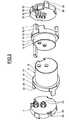
- the connector as illustrated in FIG. 1comprises a first part 1 and a second part 2, the first part 1 being here a fixed part comprising female contacts 3 and the second part 2 being a movable part carrying male contacts 4.
- the first part 1comprises a housing 5 in which the contacts 3 are maintained by an insulator composed of a front part 6 and a rear part 7.
- the second part 2comprises a housing 8 in which the contacts 4 are held by a compound insulator a front part 9 and a rear part 10.
- the housing 8carries by elsewhere a locking ring 11 which makes it possible to lock the two housings 5 and 8 one on the other, in the coupled position of the two connector parts 1 and 2. This locking is not part of the present invention and will not be described in more detail.
- the two parts 6, 7 and 9, 10 of the insulation of the two connector parts 1 and 2are intended for a round connector with two contacts.
- the two insulating parts 6, 7 of the connector part 1differ from the two insulating parts 9, 10 of the connector part 2, essentially by the length of the front parts 6, 9 and by the dimensions of the holes provided in these parts 6, 9 to receive, one female contacts 3 and the other male contacts 4.
- the general structure of parts 6 and 9, 10 on the one hand and 7 and 10, on the other handis identical, as is the way in which these parts cooperate with each other, with contacts 3, 4 and with boxes 5 and 8. This is the reason why the description that goes follow will be given only for connector part 1, i.e. for parts 3, 5, 6 and 7, but this description applies also to connector part 2, i.e. to parts 4, 8, 9 and 10, respectively.
- Contact 3includes, for its maintenance in the part of connector 1, a retaining flange 12 by which the contact 3 is positioned axially with respect to the two parts 6 and 7.
- the front part 6has, for each contact 3, an axial hole 13 which receives the part of contact 3 located in front of the flange 12, this hole 13 connecting at the rear, by a shoulder 14, to a tapered enlargement 15.
- the front part 6comprises a cylindrical front portion 16 to which it is connected, towards the rear, via a shoulder 17, a portion 18 cylindrical of increased diameter, carrying three bosses 19 distributed at 120 ° from each other.
- three legs 20 in overhangsprotrude rearward, each of these legs 19 bearing at its free end an inner tooth 21 of trapezoidal shape.
- the rear part 7comprises, for each contact 3, a hole for cylindrical passage 22 extended forwards by four fingers 23 in cantilevered.
- the diameter of the hole 22is very slightly greater than the diameter of the collar 12 of the contacts 3 and the fingers 23 converge so that the reciprocal distance of the fingers 23 opposite to the free ends of the latter, corresponds substantially to the diameter of the part of contact 3 located behind the flange 12.
- Each finger 23also has, on the inner side, a boss 24 between its connection to the rear part 7 and its free end.
- the rear part 7has a lateral surface cylindrical having the same diameter as the portion 18 of the portion before 6, but with three notches 25 which correspond to the three legs 20 of the front part 6 and have a notch 26 whose profile corresponds to the shape of the tooth 21, and a rear flank 27.
- the rear part 7has, in its lateral surface outside, in three places offset from the notches 25, three locking tabs 28 projecting rearwardly and having an outer shoulder 29 by which the legs 28 can be supported in a groove 30 of the housing 5 in the position according to Figure 1, position in which the cylindrical portion 16 of the front part 6 is fully engaged in the front portion 31 cylindrical housing 5, its shoulder 17 bearing against a shoulder 32 of the housing 5.
- the two parts 6 and 7 of the insulationare spaced from each other, this position being defined by latching of tooth 21 of lugs 20 of part 6 in notch 26 notches 25 of part 7.
- the fingers 23are clear of housing 15.
- Contacts 3can be engaged from the rear, through the holes 22 of the rear part 7 until the flanges 12 come to bear against the bosses 24 of the fingers 23 ( Figure 4), which constitute a clearly perceptible hard point.
- the two connector parts 1 and 2can be coupled and locked in the coupled state using the ring 11, as illustrated by figure 1.
- the connector part 1could comprise by example of male contacts instead of female contacts, or male contacts and female contacts, the other connector part 2 with additional contacts.
- the connectorcould also be a non-circular connector and the number of contacts could be different from two.
- a considerable advantage of the embodiment shown and describedconsists in the fact that all parts of the connector and particular the two parts 6, 7 and 9, 10 of each connector part 1, 2, can be made of plastic by simple molding, without resuming machining. Each connector half is made up like this a minimum number of simple manufacturing parts, which reduces the cost of the connector as a whole.
Landscapes
- Connector Housings Or Holding Contact Members (AREA)
- Details Of Connecting Devices For Male And Female Coupling (AREA)
Description
Translated fromFrenchLa présente invention se rapporte à un connecteur électriqueformé de deux parties destinées à coopérer l'une avec l'autre par leurscôtés avant respectifs, chacune desdites parties comprenant un boítieret au moins un contact comportant une collerette de retenue etmaintenu dans le boítier par un isolant dans lequel le contact estenfiché depuis le côté arrière et retenu par ladite collerette.The present invention relates to an electrical connectorformed of two parts intended to cooperate with each other by theirrespective front sides, each of said parts comprising a housingand at least one contact comprising a retaining flange andheld in the housing by an insulator in which the contact isplugged in from the rear side and retained by said flange.
Pour la structure générale de tels connecteurs, ainsi que de leurscontacts qui peuvent, par exemple, être directement fixés auxextrémités des conducteurs à connecter, il est possible de se référerpar exemple aux documents FR-A-2 115 556 et FR-A-2 575 912.For the general structure of such connectors, as well as theircontacts which can, for example, be directly attached toends of the conductors to be connected, it is possible to referfor example in documents FR-A-2 115 556 and FR-A-2 575 912.
Un problème qui se pose avec de tels connecteurs concernel'assurance que les contacts sont correctement enfichés dans les partiesde connecteurs. En effet, malgré tous les contrôles possibles dits decontinuité électrique, il s'avère qu'il subsiste encore toujours, sur detels connecteurs, des mauvais contacts qui sont dus essentiellement àdes contacts incomplètement enfichés, donnant lieu, enfonctionnement, sous l'effet de vibrations, à des microcoupures semanifestant sous forme de défauts aléatoires, dont la localisation estextrêmement difficile.One problem with such connectors isensuring that the contacts are correctly inserted in the partsconnectors. Indeed, despite all the possible so-called controlselectrical continuity, it turns out that it still still exists, onsuch connectors, bad contacts which are mainly due toincomplete plug-in contacts, giving rise, inoperation, under the effect of vibrations, to micro-cutsmanifesting in the form of random faults, the location of which isextremely difficult.
C'est la raison pour laquelle la présente invention a pour but defournir un connecteur électrique de structure simple procurant, par uneconformation particulière du connecteur, une sécurité accrue quant àl'enfichage correct des contacts dans les parties de connecteur et de cefait une sécurité de contact nettement améliorée.This is the reason why the present invention aims toprovide an electrical connector of simple structure providing, by aparticular conformation of the connector, increased security as tothe correct insertion of the contacts in the connector parts and thismakes contact security significantly improved.
Le connecteur électrique conforme à l'invention, définit par la revendication 1, est formé de deuxparties destinées à coopérer l'une avec l'autre par leurs côtés avantrespectifs, chacune desdites parties comprenant un boítier et au moinsun contact comportant une collerette de retenue et maintenu dans leboítier par un isolant dans lequel le contact est enfiché depuis le côtéarrière et retenu par ladite collerette. L'isolant est divisétransversalement à la direction d'enfichage du contact en une partieavant et une partie arrière comprenant des moyens de positionnementpermettant de les maintenir dans une première position réciproque dans laquelle elles sont espacées l'une de l'autre et dans une secondeposition réciproque dans laquelle elles sont rapprochées l'une del'autre. La partie arrière comporte, pour chaque contact, des moyens derétention permettant le passage de la collerette du contact en subissantune déformation élastique à leur franchissement par la collerette. Lapartie avant comporte, pour chaque contact, des moyens decondamnation qui sont conçus de manière à
Ainsi, pour permettre l'enfichage des contacts dans les parties duconnecteur conforme à l'invention, les deux parties de l'isolant doiventobligatoirement se trouver dans la première position, puisque ce n'estque dans cette position que les moyens de rétention prévus sur lapartie arrière permettent le passage de la collerette de retenue dechaque contact. Du fait que le franchissement des moyens de rétentionpar la collerette de retenue du contact implique une déformationélastique des moyens de rétention, ce franchissement est nettementperceptible pour l'opérateur. Ce n'est qu'ensuite, dans un deuxièmetemps, que l'opérateur amène les deux parties de l'isolant à la secondeposition, ce passage de la première à la seconde position n'étantpossible qu'à condition que les collerettes de retenue aientcomplètement franchi les moyens de rétention.Thus, to allow the insertion of the contacts in the parts of theconnector according to the invention, the two parts of the insulation mustmust be in the first position, since it is notthat in this position that the retention means provided on therear part allow the passage of the retaining flangeevery contact. The fact that the crossing of means of detentionby the contact retaining flange implies a deformationelastic retention means, this crossing is clearlynoticeable to the operator. Only then, in a secondtime, that the operator brings the two parts of the insulation to the secondposition, this transition from the first to the second position not beingpossible as long as the retaining flanges havecompletely crossed the means of retention.
De préférence, les moyens de rétention sur la partie arrière del'isolant comprennent, pour chaque contact, un trou de passage pour lecontact avec sa collerette de retenue et au moins un doigt flexibles'étendant depuis ledit trou en direction de la partie avant de manière que ledit doigt subisse une flexion élastique au passage de la collerettede retenue. Les moyens de condamnation sur la partie avant del'isolant comprennent pour chaque contact un trou dans ladite partiepour recevoir la partie du contact située en avant de la collerette deretenue et, en arrière de ce trou, un logement conformé de manière
Suivant un mode de réalisation préféré, les moyens de rétentionsur la partie arrière de l'isolant comprennent, pour chaque contact,plusieurs doigts répartis à la manière de pétales sur un cercle, et lelogement dans la partie avant de l'isolant est constitué par unévidement de révolution pouvant recevoir lesdits doigts.According to a preferred embodiment, the retention meanson the rear part of the insulation include, for each contact,several fingers distributed like petals on a circle, and thehousing in the front part of the insulation consists of arecess of revolution able to receive said fingers.
De préférence, ledit logement se raccorde au trou recevant lapartie du contact située en avant de la collerette de retenue par unépaulement servant de butée de limitation de la profondeur d'enfichagedu contact.Preferably, said housing is connected to the hole receiving thepart of the contact located in front of the retaining flange by ashoulder serving as stop for limiting the insertion depthof the contact.
Les doigts constituant les moyens de rétention peuventavantageusement converger en direction de leur extrémité libre etcomporter un bossage intérieur entre leur emplacement deraccordement au trou de passage de la partie arrière de l'isolant et leurextrémité libre. Ce bossage constitue un point dur qui est nettementperceptible par l'opérateur lors de l'enfichage.The fingers constituting the retention means canadvantageously converge towards their free end andhave an interior boss between their locationconnection to the through hole of the rear part of the insulation and theirfree end. This boss constitutes a hard point which is clearlynoticeable by the operator when plugging in.
De préférence, les moyens de positionnement des deux parties del'isolant l'une par rapport à l'autre dans la première et dans la secondepositions réciproques, peuvent comprendre des moyens d'encliquetageréalisés d'une seule pièce avec lesdites parties.Preferably, the means for positioning the two parts ofinsulating it from each other in the first and in the secondreciprocal positions, may include latching meansmade in one piece with said parts.
Lesdits moyens de positionnement peuvent en particuliercomprendre sur l'une des parties de l'isolant, une patte en porte-à-fauxfaisant saillie vers l'autre partie et portant une dent à son extrémitélibre et sur l'autre partie deux crans transversaux espacés de manière àpermettre, par flexion de ladite patte, l'encliquetage de la dent de cettedernière dans l'un et l'autre desdits crans.Said positioning means can in particularinclude on one part of the insulation, a cantilever tabprojecting towards the other party and carrying a tooth at its endfree and on the other part two transverse notches spaced so as toallow, by bending of said tab, the snap-fastening of the tooth of thislast in both of said notches.
Ladite patte peut de préférence être formée sur l'une des parties de l'isolant de manière à fléchir vers l'extérieur et dans une position telleque cette flexion soit empêchée par le boítier lorsque les deux partiesde l'isolant sont montées dans le boítier.Said tab can preferably be formed on one of the parts ofthe insulation so as to flex outwards and in such a positionthat this bending is prevented by the housing when the two partsof the insulation are mounted in the housing.
En se référant aux dessins annexés, on va décrire ci-après plus endétail un mode de réalisation illustratif et non limitatif d'unconnecteur conforme à l'invention; sur les dessins :
Le connecteur tel qu'illustré par la figure 1 comprend unepremière partie 1 et une seconde partie 2, la première partie 1 étant iciune partie fixe comportant des contacts femelles 3 et la seconde partie2 étant une partie mobile portant des contacts mâles 4.The connector as illustrated in FIG. 1 comprises afirst part 1 and a second part 2, the first part 1 being herea fixed part comprising
La première partie 1 comprend un boítier 5 dans lequel lescontacts 3 sont maintenus par un isolant composé d'une partie avant 6et d'une partie arrière 7.The first part 1 comprises a housing 5 in which the
De façon correspondante, la seconde partie 2 comprend un boítier8 dans lequel les contacts 4 sont maintenus par un isolant composéd'une partie avant 9 et d'une partie arrière 10. Le boítier 8 porte parailleurs une bague de verrouillage 11 qui permet de verrouiller lesdeux boítiers 5 et 8 l'un sur l'autre, en position accouplée des deuxparties de connecteur 1 et 2. Ce verrouillage ne relève pas de laprésente invention et ne sera pas décrit plus en détail.Correspondingly, the second part 2 comprises a
Tel que cela apparaít sur les figures 2 et 3, les deux parties 6, 7 et9, 10 de l'isolant des deux parties de connecteur 1 et 2 sont destinées àun connecteur rond à deux contacts.As shown in Figures 2 and 3, the two
Les deux parties d'isolant 6, 7 de la partie de connecteur 1diffèrent des deux parties d'isolant 9, 10 de la partie de connecteur 2,essentiellement par la longueur des parties avant 6, 9 et par lesdimensions des trous prévus dans ces parties 6, 9 pour recevoir, l'unedes contacts femelles 3 et l'autre des contacts mâles 4. A part cesdifférences, la structure générale des parties 6 et 9, 10 d'une part et 7et 10, d'autre part, est identique, de même que la manière dont cesparties coopèrent l'une avec l'autre, avec les contacts 3, 4 et avec lesboítiers 5 et 8. C'est la raison pour laquelle la description qui vasuivre sera donnée uniquement pour la partie de connecteur 1, c'est-à-direpour les pièces 3, 5, 6 et 7, mais cette description s'appliqueégalement à la partie de connecteur 2, c'est-à-dire aux pièces 4, 8, 9 et10, respectivement.The two
Le contact 3 comporte, pour son maintien dans la partie deconnecteur 1, une collerette de retenue 12 grâce à laquelle le contact 3est positionné axialement par rapport aux deux parties 6 et 7.
La partie avant 6 présente, pour chaque contact 3, un trou axial 13qui reçoit la partie du contact 3 située en avant de la collerette 12, cetrou 13 se raccordant à l'arrière, par un épaulement 14, à unélargissement tronconique 15. Extérieurement, la partie avant 6comprend une portion antérieure 16 cylindrique à laquelle se raccorde,vers l'arrière, par l'intermédiaire d'un épaulement 17, une portion 18cylindrique de diamètre accru, portant trois bossages 19 répartis à120° les uns des autres. A l'endroit des bossages 19, trois pattes 20 enporte-à-faux font saillie vers l'arrière, chacune de ces pattes 19 portantà son extrémité libre une dent intérieure 21 de forme trapézoïdale.The
La partie arrière 7 comporte, pour chaque contact 3, un trou depassage 22 cylindrique prolongé vers l'avant par quatre doigts 23 enporte-à-faux. Le diamètre du trou 22 est très légèrement supérieur audiamètre de la collerette 12 des contacts 3 et les doigts 23 convergentde manière que la distance réciproque des doigts 23 opposée, auxextrémités libres de ces derniers, corresponde sensiblement au diamètre de la partie du contact 3 située en arrière de la collerette 12.Chaque doigt 23 comporte par ailleurs, sur le côté intérieur, unbossage 24 entre son raccordement à la partie arrière 7 et sonextrémité libre.The
Extérieurement, la partie arrière 7 présente une surface latéralecylindrique ayant le même diamètre que la portion 18 de la partieavant 6, mais avec trois encoches 25 qui correspondent aux trois pattes20 de la partie avant 6 et présentent un cran 26 dont le profilcorrespond à la forme de la dent 21, et un flanc arrière 27.Externally, the
Par ailleurs, la partie arrière 7 comporte, dans sa surface latéraleextérieure, en trois endroits décalés par rapport aux encoches 25, troispattes de blocage 28 s'étendant en porte-à-faux vers l'arrière etcomportant un épaulement extérieur 29 grâce auquel les pattes 28peuvent prendre appui dans une gorge 30 du boítier 5 dans la positionselon la figure 1, position dans laquelle la portion cylindrique 16 de lapartie avant 6 est engagée à fond dans la portion antérieure 31cylindrique du boítier 5, son épaulement 17 portant contre unépaulement 32 du boítier 5.Furthermore, the
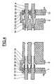
En se référant aux figures 4 à 6, on va décrire ci-après lesdifférentes étapes d'enfichage des contacts 3 dans la partie deconnecteur 1 (l'enfichage des contacts 4 dans la partie de connecteur 2s'effectue de la même manière), seules les deux parties de l'isolant desdeux parties de connecteur 1 et 2 étant illustrées sur ces figures.Referring to Figures 4 to 6, we will describe below thedifferent steps for inserting the
Avant l'enfichage des contacts 3, les deux parties 6 et 7 del'isolant sont écartées l'une de l'autre, cette position étant définie parl'encliquetage de la dent 21 des pattes 20 de la partie 6 dans le cran 26des encoches 25 de la partie 7. Dans cette position, les doigts 23 sontdégagés du logement 15. Les contacts 3 peuvent être engagés depuisl'arrière, à travers les trous 22 de la partie arrière 7 jusqu'à ce que lescollerettes 12 viennent porter contre les bossages 24 des doigts 23(figure 4), qui constituent un point dur nettement perceptible.Before inserting the
Après que ce point dur ait été franchi par application d'unepoussée accrue aux contacts 3, l'enfichage de ces derniers peutcontinuer, moyennant un écartement élastique des doigts 23 par lescollerettes 12, jusqu'à l'appui des collerettes 12 contre les épaulements 14 au fond des logements 15, épaulements qui constituent la butéed'enfichage pour les contacts 3 (figure 5).After this hard point has been crossed by applying aincreased thrust at
Ensuite, en exerçant sur la partie 7 une poussée en direction de lapartie 6, en vue de leur rapprochement réciproque, il est possible dedégager les dents 21 des crans 26, par flexion des pattes 20 versl'extérieur, et d'amener les deux parties 6, 7 à la position réciproquesuivant la figure 6 dans laquelle les deux parties sont rapprochéesl'une de l'autre et sont maintenues par encliquetage des dents 21derrière les épaulements 27. Pendant ce mouvement de rapprochementdes parties 6, 7, les doigts 23 sont enfoncés dans les logements 15,derrière les collerettes 12 des contacts 3, ce qui fait que les collerettes12 se trouvent emprisonnées entre les épaulements 14 et les extrémitéslibres des doigts 23. Ces derniers, dans cette position, sont bloquéspar le logement 15 qui les entoure (voir figure 1) et les empêche des'écarter pour permettre le passage d'une collerette 12.Then, by pushing on
Il convient de remarquer que, si pour une raison quelconque, dansla position des parties 6, 7 suivant la figure 5, un contact 3 n'avait pasété suffisamment enfiché pour que sa collerette 12 ait franchi lesextrémités libres des doigts 23, sa collerette 12 se trouveraitimmobilisée entre les doigts 23 et maintiendrait ces derniers écartés;les deux parties 6 et 7 ne pourraient alors pas être amenées à laposition rapprochée suivant la figure 6, du fait que les doigts 23écartés ne pourraient pas être engagés dans le logement 15.L'opérateur serait ainsi averti avec certitude de cette situation etpourrait faire le nécessaire pour y remédier.It should be noted that, if for any reason inthe position of the
Ce n'est que lorsque les deux parties 6, 7 de l'isolant ont étéamenées à la position réciproque rapprochée suivant la figure 6, quel'ensemble comprenant les deux parties 6, 7 et les contacts 3, estinséré dans le boítier 5 et bloqué dans ce dernier par les pattes 28,comme représenté sur la figure 1.It is only when the two
Après que les mêmes opérations que celles décrites au sujet de lapartie de connecteur 1 ont été effectuées sur la partie de connecteur 2,les deux parties de connecteur 1 et 2 peuvent être accouplées etverrouillées à l'état accouplé à l'aide de la bague 11, comme illustrépar la figure 1.After the same operations as those described for theconnector part 1 were made on connector part 2,the two connector parts 1 and 2 can be coupled andlocked in the coupled state using the
Il va de soi que le mode de réalisation illustré et décrit n'a étédonné qu'à titre d'exemple indicatif et non limitatif et que denombreuses modifications et variantes sont possibles dans le cadre del'invention. Ainsi, la partie de connecteur 1 pourrait comporter parexemple des contacts mâles au lieu de contacts femelles, ou descontacts mâles et des contacts femelles, l'autre partie de connecteur 2comportant des contacts complémentaires. Le connecteur pourraitégalement être un connecteur non circulaire et le nombre des contactspourrait être différent de deux.It goes without saying that the embodiment illustrated and described has not beengiven as an indicative and non-limiting example and thatmany modifications and variants are possible within the framework ofthe invention. Thus, the connector part 1 could comprise byexample of male contacts instead of female contacts, ormale contacts and female contacts, the other connector part 2with additional contacts. The connector couldalso be a non-circular connector and the number of contactscould be different from two.
On reconnaít en particulier sur les figures 2 et 3, des moyens dedétrompage prévus sur les parties 6, 7 et 9, 10 de l'isolant des deuxparties de connecteur, mais ces moyens ne sont pas décrits dans lamesure où ils n'entrent pas dans le cadre de la présente invention.We recognize in particular in Figures 2 and 3, means ofcoding provided on
D'autres modes de réalisation seraient également concevables ence qui concerne les moyens de positionnement réciproques des deuxparties de l'isolant de chaque partie de connecteur, et les doigts 23ainsi que le logement 15 qui reçoit lesdits doigts en vue de leurblocage, pourraient être remplacés par d'autres moyens de rétentiondes collerettes 12 des contacts et par d'autres moyens de condamnationou blocage de ces moyens de rétention.Other embodiments would also be conceivable inwith regard to the reciprocal positioning means of the twoinsulator parts of each connector part, and
Un avantage considérable du mode de réalisation représenté etdécrit consiste dans le fait que toutes les pièces du connecteur et enparticulier les deux parties 6, 7 et 9, 10 de chaque partie de connecteur1, 2, peuvent être réalisées en matière plastique par simple moulage,sans reprise d'usinage. Chaque moitié de connecteur se compose ainsid'un nombre minimal de pièces de fabrication simple, ce qui réduit lecoût du connecteur dans son ensemble.A considerable advantage of the embodiment shown anddescribed consists in the fact that all parts of the connector andparticular the two
Claims (7)
- Electrical connector formed of two connectorparts (1, 2) each including an insulator body (5, 6, 7;8, 9, 10) into which at least one electrical contact(3,4) comprising a retaining collar (12) is plugged fromthe rear side and held at the level of its collar, theinsulator body of each connector part (1, 2) beingdivided transverse to the contact plug-in direction intoa rear part (7, 10) and a front part (6, 9) includingpositioning means (21, 27) allowing them to be held in areciprocal position in which they are brought closetogether, the rear part having for each contact aretention means including several cantilevered pins (23)projecting like petals towards the front part in such away as to separate by resilient distortion when acontact collar is passed over them, and the front parthaving for each contact an immobilisation means toimmobilise said retention component in said reciprocallyclose position, including a housing (15), configured insuch a way that said pins are not able to separate whenthey are engaged in said housing in said reciprocally close position, said housing ending on the side awayfrom the rear part with a shoulder (14) acting as a stoplimiting the depth to which the contacts can be pluggedin,characterised by the fact that said rear part (7,10) and said front part (6, 9), together constituting aninsulator intended to be mounted in a casing (5, 8) ofeach connector part (1, 2) include at the same timepositioning means (21, 27) for holding them in saidreciprocally close position and positioning means (21,26) for holding them in a reciprocal position in whichsaid two parts (6, 9; 7, 10) are spaced apart from eachother, said positioning means (21; 26, 27), said pins(23) and said housings (15) being configured in such away thata) said housings do not engage with said pins andoffer no resistance to the separation of said pins byresilient distortion when a contact collar is passedover them, in said reciprocally separated position ofthe two insulator parts, andb) engage with said pins in said reciprocally closeposition of the two insulator parts in order tob1) not only prevent a contact collar from passingover said pins in said reciprocally close position butagainb2) prevent transfer from said reciprocallyseparated position to said reciprocally close positionwhen a contact collar has passed only partially oversaid pins.
- Connector according to claim 1,characterised bythe fact that each pin (23) comprises, on the inner side, a projection (24) between its connection to therear part and its free end.
- Connector according to any one of the previousclaims,characterised by the fact that the positioningmeans on the two parts (6, 7; 9, 10) of the insulatorinclude ratchet means made of a single piece with thetwo parts.
- Connector according to claim 3,characterised bythe fact that the ratchet means include, on one of theparts, a cantilevered lug (20), projecting towards theother part in such a way as to be able to bendresiliently, this lug bearing a tooth (21) at its freeend, and on the other part two transverse notches (26,27) spaced out in such a way as to allow said tooth toratch itself into one and the other of said notches.
- Connector according to claim 4,characterised bythe fact that said lug (20) is formed on one of the twoparts in such a way as to bend outwards, in a positionsuch that this bending is inhibited by the casing (5,8)when the two parts are mounted in the casing.
- Connector according to any one of the previousclaims,characterised by the fact that means (28) forlocking the two parts (6, 7; 9, 10) of the insulator inthe casing (5, 8), in said second position, are formedon one of said parts.
- Connector according to any one of the previousclaims,characterised by the fact that the two parts (6,7; 9, 10) of the insulator are moulded in a plasticmaterial, without further machining, with saidpositioning, retention, immobilisation and lockingmeans.
Applications Claiming Priority (2)
| Application Number | Priority Date | Filing Date | Title |
|---|---|---|---|
| FR9707148 | 1997-06-10 | ||
| FR9707148AFR2764446B1 (en) | 1997-06-10 | 1997-06-10 | ELECTRICAL CONNECTOR WITH IMPROVED CONTACT SECURITY |
Publications (3)
| Publication Number | Publication Date |
|---|---|
| EP0884806A2 EP0884806A2 (en) | 1998-12-16 |
| EP0884806A3 EP0884806A3 (en) | 1999-03-24 |
| EP0884806B1true EP0884806B1 (en) | 2004-04-07 |
Family
ID=9507789
Family Applications (1)
| Application Number | Title | Priority Date | Filing Date |
|---|---|---|---|
| EP98401329AExpired - LifetimeEP0884806B1 (en) | 1997-06-10 | 1998-06-04 | Electrical connector with improved contact security |
Country Status (5)
| Country | Link |
|---|---|
| US (1) | US6132262A (en) |
| EP (1) | EP0884806B1 (en) |
| DE (1) | DE69822925T2 (en) |
| ES (1) | ES2217518T3 (en) |
| FR (1) | FR2764446B1 (en) |
Families Citing this family (4)
| Publication number | Priority date | Publication date | Assignee | Title |
|---|---|---|---|---|
| US20040097912A1 (en)* | 2002-11-18 | 2004-05-20 | Gonnering Wayne J. | Electrosurgical generator and method with removable front panel having replaceable electrical connection sockets and illuminated receptacles |
| DE202008014168U1 (en)* | 2008-10-24 | 2010-03-11 | Weidmüller Interface GmbH & Co. KG | Plug connection with a male and a female part and these receiving adapter housings |
| US8926363B2 (en)* | 2012-03-02 | 2015-01-06 | Tyco Electronics Corporation | Electrical connector assembly |
| US20170005444A1 (en)* | 2014-04-11 | 2017-01-05 | HARTING Electronics GmbH | Plug-in connector |
Family Cites Families (11)
| Publication number | Priority date | Publication date | Assignee | Title |
|---|---|---|---|---|
| FR2115556A5 (en)* | 1970-11-24 | 1972-07-07 | Lb Air | |
| FR2575612B1 (en)* | 1985-01-03 | 1987-04-30 | Lb Air | METHOD FOR MANUFACTURING AN ELECTRICAL CONNECTION DEVICE |
| JPH0430793Y2 (en)* | 1988-05-06 | 1992-07-24 | ||
| GB8827756D0 (en)* | 1988-11-28 | 1988-12-29 | Amp Great Britain | Electrical connector housing assembly |
| MY104824A (en)* | 1989-03-17 | 1994-06-30 | Whitaker Corp | Electrical connector |
| FR2681735B1 (en)* | 1991-09-19 | 1995-07-28 | Souriau & Cie | ELECTRICAL CONNECTOR WITH LOCKING RING. |
| FR2714536B1 (en)* | 1993-12-27 | 1996-01-19 | Cinch Connecteurs Sa | Improvements to the components of electrical connector housings. |
| JP2921639B2 (en)* | 1994-03-07 | 1999-07-19 | 矢崎総業株式会社 | Double locking connector and locking release structure |
| FR2727258B1 (en)* | 1994-11-21 | 1996-12-20 | Cinch Connecteurs Sa | ELECTRICAL CONNECTOR |
| US5520553A (en)* | 1994-12-08 | 1996-05-28 | Molex Incorporated | Connector with a front end mounted terminal position assurance system |
| FR2729794A1 (en)* | 1995-01-19 | 1996-07-26 | Cinch Connecteurs Sa | Locking assembly for electrical connector |
- 1997
- 1997-06-10FRFR9707148Apatent/FR2764446B1/ennot_activeExpired - Fee Related
- 1998
- 1998-06-02USUS09/088,489patent/US6132262A/ennot_activeExpired - Lifetime
- 1998-06-04DEDE69822925Tpatent/DE69822925T2/ennot_activeExpired - Lifetime
- 1998-06-04EPEP98401329Apatent/EP0884806B1/ennot_activeExpired - Lifetime
- 1998-06-04ESES98401329Tpatent/ES2217518T3/ennot_activeExpired - Lifetime
Also Published As
| Publication number | Publication date |
|---|---|
| DE69822925T2 (en) | 2005-03-10 |
| FR2764446B1 (en) | 2001-10-26 |
| EP0884806A2 (en) | 1998-12-16 |
| FR2764446A1 (en) | 1998-12-11 |
| DE69822925D1 (en) | 2004-05-13 |
| ES2217518T3 (en) | 2004-11-01 |
| EP0884806A3 (en) | 1999-03-24 |
| US6132262A (en) | 2000-10-17 |
Similar Documents
| Publication | Publication Date | Title |
|---|---|---|
| CA2947799C (en) | Secure tubular connectors with automatic connection | |
| EP0881713B1 (en) | Lockable electric connector | |
| FR2758662A1 (en) | MOBILE CONTACT COAXIAL ELECTRIC CONNECTOR ELEMENT AND COAXIAL ELECTRIC CONNECTOR INCLUDING SUCH A CONNECTOR ELEMENT | |
| EP1154527B1 (en) | Device to connect a coaxial cable to a printed circuit board | |
| FR2715004A1 (en) | Microminiature coaxial connector with snap lock. | |
| EP0898334B1 (en) | Electrical connector released by traction | |
| FR2808862A1 (en) | Quick connector for pipe end pieces comprises female part which receives end piece and bushing, in which female part slides, has projecting end with locking tab | |
| EP0884806B1 (en) | Electrical connector with improved contact security | |
| EP0866521B1 (en) | Male connector for printed circuit board | |
| WO2008145878A1 (en) | Accessory of the backshell type for connector | |
| EP0685911B1 (en) | Electrical coaxial connector element comprising switching means and electrical connector including such a connector element | |
| FR2778502A1 (en) | Electrical connector with multiple male terminal pins | |
| EP0664578A1 (en) | Connector for coaxial cable | |
| FR2677496A1 (en) | ELECTRICAL CONNECTION BY SHEETS IN PARTICULAR FOR MOTOR VEHICLES OR THE LIKE. | |
| EP0869580B1 (en) | Connector with integrated secondary lock | |
| EP1286427A1 (en) | Terminal-block with lock-arm for plug connector | |
| FR2755306A1 (en) | MALE CONNECTING DEVICE ADAPTABLE TO DIFFERENT DIAMETERS OF FEMALE SOCKET | |
| WO2004064201A1 (en) | Elbow-shaped electric plug | |
| EP0469134B1 (en) | Locking connector with lever | |
| FR2704988A1 (en) | Electrical connector. | |
| EP4124520A1 (en) | Connection device between a wiper blade and a drive arm | |
| FR2758213A1 (en) | Female electrical contact unit for connectors | |
| EP0674357A1 (en) | Improvements to housing parts of electrical connectors | |
| FR2918805A1 (en) | ELECTRICAL CONNECTION TERMINAL AUTODENUDANTE. | |
| EP2120243B1 (en) | Adapter for test plug |
Legal Events
| Date | Code | Title | Description |
|---|---|---|---|
| PUAI | Public reference made under article 153(3) epc to a published international application that has entered the european phase | Free format text:ORIGINAL CODE: 0009012 | |
| AK | Designated contracting states | Kind code of ref document:A2 Designated state(s):BE DE ES FR GB IT LU NL | |
| AX | Request for extension of the european patent | Free format text:AL;LT;LV;MK;RO;SI | |
| PUAL | Search report despatched | Free format text:ORIGINAL CODE: 0009013 | |
| AK | Designated contracting states | Kind code of ref document:A3 Designated state(s):AT BE CH CY DE DK ES FI FR GB GR IE IT LI LU MC NL PT SE | |
| AX | Request for extension of the european patent | Free format text:AL;LT;LV;MK;RO;SI | |
| 17P | Request for examination filed | Effective date:19990924 | |
| AKX | Designation fees paid | Free format text:BE DE ES FR GB IT LU NL | |
| 17Q | First examination report despatched | Effective date:20001103 | |
| RAP1 | Party data changed (applicant data changed or rights of an application transferred) | Owner name:AMPHENOL-AIR LB GMBH | |
| GRAH | Despatch of communication of intention to grant a patent | Free format text:ORIGINAL CODE: EPIDOS IGRA | |
| GRAH | Despatch of communication of intention to grant a patent | Free format text:ORIGINAL CODE: EPIDOS IGRA | |
| GRAA | (expected) grant | Free format text:ORIGINAL CODE: 0009210 | |
| AK | Designated contracting states | Kind code of ref document:B1 Designated state(s):BE DE ES FR GB IT LU NL | |
| REG | Reference to a national code | Ref country code:GB Ref legal event code:FG4D Free format text:NOT ENGLISH | |
| REF | Corresponds to: | Ref document number:69822925 Country of ref document:DE Date of ref document:20040513 Kind code of ref document:P | |
| GBT | Gb: translation of ep patent filed (gb section 77(6)(a)/1977) | Effective date:20040625 | |
| REG | Reference to a national code | Ref country code:ES Ref legal event code:FG2A Ref document number:2217518 Country of ref document:ES Kind code of ref document:T3 | |
| PLBE | No opposition filed within time limit | Free format text:ORIGINAL CODE: 0009261 | |
| STAA | Information on the status of an ep patent application or granted ep patent | Free format text:STATUS: NO OPPOSITION FILED WITHIN TIME LIMIT | |
| 26N | No opposition filed | Effective date:20050110 | |
| REG | Reference to a national code | Ref country code:FR Ref legal event code:PLFP Year of fee payment:19 | |
| REG | Reference to a national code | Ref country code:FR Ref legal event code:PLFP Year of fee payment:20 | |
| PGFP | Annual fee paid to national office [announced via postgrant information from national office to epo] | Ref country code:NL Payment date:20170515 Year of fee payment:20 | |
| PGFP | Annual fee paid to national office [announced via postgrant information from national office to epo] | Ref country code:FR Payment date:20170420 Year of fee payment:20 Ref country code:DE Payment date:20170614 Year of fee payment:20 Ref country code:GB Payment date:20170616 Year of fee payment:20 | |
| PGFP | Annual fee paid to national office [announced via postgrant information from national office to epo] | Ref country code:IT Payment date:20170619 Year of fee payment:20 Ref country code:BE Payment date:20170627 Year of fee payment:20 Ref country code:LU Payment date:20170516 Year of fee payment:20 | |
| PGFP | Annual fee paid to national office [announced via postgrant information from national office to epo] | Ref country code:ES Payment date:20170707 Year of fee payment:20 | |
| REG | Reference to a national code | Ref country code:DE Ref legal event code:R071 Ref document number:69822925 Country of ref document:DE | |
| REG | Reference to a national code | Ref country code:NL Ref legal event code:MK Effective date:20180603 | |
| REG | Reference to a national code | Ref country code:GB Ref legal event code:PE20 Expiry date:20180603 | |
| PG25 | Lapsed in a contracting state [announced via postgrant information from national office to epo] | Ref country code:GB Free format text:LAPSE BECAUSE OF EXPIRATION OF PROTECTION Effective date:20180603 | |
| REG | Reference to a national code | Ref country code:BE Ref legal event code:MK Effective date:20180604 | |
| REG | Reference to a national code | Ref country code:ES Ref legal event code:FD2A Effective date:20200902 | |
| PG25 | Lapsed in a contracting state [announced via postgrant information from national office to epo] | Ref country code:ES Free format text:LAPSE BECAUSE OF EXPIRATION OF PROTECTION Effective date:20180605 |