EP0884449B1 - Rotary drill bits - Google Patents
Rotary drill bitsDownload PDFInfo
- Publication number
- EP0884449B1 EP0884449B1EP98304500AEP98304500AEP0884449B1EP 0884449 B1EP0884449 B1EP 0884449B1EP 98304500 AEP98304500 AEP 98304500AEP 98304500 AEP98304500 AEP 98304500AEP 0884449 B1EP0884449 B1EP 0884449B1
- Authority
- EP
- European Patent Office
- Prior art keywords
- cutters
- primary
- drill bit
- blade
- bit according
- Prior art date
- Legal status (The legal status is an assumption and is not a legal conclusion. Google has not performed a legal analysis and makes no representation as to the accuracy of the status listed.)
- Expired - Lifetime
Links
- 238000005520cutting processMethods0.000claimsdescription64
- 238000005553drillingMethods0.000claimsdescription20
- 239000012530fluidSubstances0.000claimsdescription18
- 230000015572biosynthetic processEffects0.000claimsdescription13
- 238000005755formation reactionMethods0.000claimsdescription13
- 230000007423decreaseEffects0.000claimsdescription4
- 238000004140cleaningMethods0.000claimsdescription2
- 238000001816coolingMethods0.000claimsdescription2
- 229910003460diamondInorganic materials0.000description5
- 239000010432diamondSubstances0.000description5
- UONOETXJSWQNOL-UHFFFAOYSA-Ntungsten carbideChemical compound[W+]#[C-]UONOETXJSWQNOL-UHFFFAOYSA-N0.000description5
- 239000000758substrateSubstances0.000description4
- 238000005299abrasionMethods0.000description2
- 229910000831SteelInorganic materials0.000description1
- 239000011230binding agentSubstances0.000description1
- 239000000969carrierSubstances0.000description1
- 238000010276constructionMethods0.000description1
- 238000006073displacement reactionMethods0.000description1
- 239000011159matrix materialSubstances0.000description1
- 229910052751metalInorganic materials0.000description1
- 239000002184metalSubstances0.000description1
- 229910001092metal group alloyInorganic materials0.000description1
- 238000000034methodMethods0.000description1
- 230000035515penetrationEffects0.000description1
- 239000000843powderSubstances0.000description1
- 238000004663powder metallurgyMethods0.000description1
- 239000007787solidSubstances0.000description1
- 239000010959steelSubstances0.000description1
Images

Classifications
- E—FIXED CONSTRUCTIONS
- E21—EARTH OR ROCK DRILLING; MINING
- E21B—EARTH OR ROCK DRILLING; OBTAINING OIL, GAS, WATER, SOLUBLE OR MELTABLE MATERIALS OR A SLURRY OF MINERALS FROM WELLS
- E21B10/00—Drill bits
- E21B10/46—Drill bits characterised by wear resisting parts, e.g. diamond inserts
- E21B10/54—Drill bits characterised by wear resisting parts, e.g. diamond inserts the bit being of the rotary drag type, e.g. fork-type bits
- E21B10/55—Drill bits characterised by wear resisting parts, e.g. diamond inserts the bit being of the rotary drag type, e.g. fork-type bits with preformed cutting elements
Definitions
- the inventionrelates to rotary drill bits for use in drilling holes in subsurface formations, and of the kind comprising a bit body having a shank for connection to a drill string, a plurality of circumferentially spaced blades on the bit body extending outwardly away from the central axis of rotation of the bit, and a plurality of cutting elements mounted along each blade.
- the inventionis particularly, but not exclusively, applicable to drill bits in which some or all of the cutters are preformed (PDC) cutters each formed, at least in part, from polycrystalline diamond.
- PDCpreformed
- One common form of cuttercomprises a tablet, usually circular or part-circular, made up of a superhard table of polycrystalline diamond, providing the front cutting face of the element, bonded to a substrate which is usually of cemented tungsten carbide.
- the bit bodymay be machined from solid metal, usually steel, or may be moulded using a powder metallurgy process in which tungsten carbide powder is infiltrated with a metal alloy binder in a furnace so as to form a hard matrix.
- the cutters on the drill bithave cutting edges which, together, define an overall cutting profile which defines the surface shape of the bottom of the bore hole which the bit drills.
- the cutting profileis substantially continuous over the leading face of the bit so as to form a comparatively smooth bottom hole profile.
- the cuttersthere are associated with at least some of the cutters further secondary cutters each of which is circumferentially spaced from an associated primary cutter but is disposed at substantially the same distance from the axis of the bit as the associated primary cutter, so as to "track" the primary cutter as the bit rotates. That is to say, the secondary cutter follows the groove cut in the formation by its associated primary cutter as the bit rotates.
- the secondary cuttersmay be so disposed that their cutting edges lie inwardly of the profile defined by the primary cutters so that each secondary cutter serves as a back-up to its associated primary cutter and only performs an effective cutting action on the formation should the primary cutter become damaged or worn so that it is no longer effective.
- US 5531281describes an arrangement having primary and secondary cutters arranged in a non-tracking formation and designed to allow the cutting of annular grooves in the formation being drilled serving to stabilise the bit against vibration.
- EP 0710765describes a tracking bit including primary and secondary cutters, the secondary cutters being positioned to follow tracks cut by a preceding primary cutter.
- US 5549171describes a drill bit having primary and secondary cutters positioned at various back rake angles.
- EP 0575198discloses a tracking cutter in which a range of cutter sizes are used on both the primary blade and the secondary blade.
- a rotary drill bitfor drilling holes in subsurface formations, comprising a bit body having a shank for connection to a drill string, a plurality of circumferentially spaced blades on the bit body extending outwardly away from the central axis of rotation of the bit, and a plurality of cutters mounted along each blade, at least the majority of which cutters are located at different distances away from the bit axis than any other cutter, said cutters including primary cutters having cutting edges which define a primary cutting profile and secondary cutters having cutting edges which define a secondary cutting profile which is disposed inwardly of the primary cutting profile with respect to the bit body, wherein the secondary cutters are of different sizes.
- the arrangement according to the inventiondiffers significantly from the prior art mentioned above in that at least the majority of the secondary cutters, instead of tracking associated primary cutters, are located at different positions as compared to the primary cutters so that no tracking occurs.
- the secondary cutterswill thus make some contribution to the cutting of the formation at all times, the contribution increasing as the primary cutters wear.
- a high rate of penetrationmay be achieved particularly in softer formations.
- the fact that the secondary cutters lie on a lower profilemay ficilitate the flow of drilling fluid between the secondary cutters and across the secondary blades, thereby reducing the tendency for bit "balling" to occur, where soft sticky formation accumulates on the surface of the bit around the cutters.
- the primary cuttersexperience wear and the secondary cutters begin to make a bigger contribution to the drilling action resulting in a smoother bottom hole profile. This may improve the steerability of the drill bit when used with a steering system.
- the primary cuttersmay be mounted on primary blades and at least some of the secondary cutters mounted on separate secondary blades.
- the primary blades and secondary bladesmay be spaced alternately apart around the axis of rotation of the bit.
- the primary bladesmay be longer than the secondary blades so as to extend into said central region of the bit body.
- Each secondary blademay be associated with a particular primary blade, each secondary cutter then being located at a position, with respect to the bit axis, which is intermediate the positions of two adjacent primary cutters on its associated primary blade.
- each secondary blademay be the next adjacent blade rearwardly of its associated primary blade with respect to the normal direction of rotation of the drill bit.
- At least some of said secondary cuttersmay be mounted on the same blades as at least some of the primary cutters.
- the secondary cuttersmay be disposed rearwardly of the primary cutters on the same blade, with respect to the normal direction of forward rotation of the drill bit.
- the secondary cuttersmay be mounted on an outer region of the blade.
- the number of secondary cuttersmay be less than the number of primary cutters on the same blade.
- the bit bodymay include a central region around the axis of rotation of the bit where only primary cutters are mounted.
- the secondary cuttersmay include cutters which are smaller or larger than at least the majority of the primary cutters. At least the majority of the secondary cutters may be smaller or larger than at least the majority of the primary cutters.
- the secondary cuttersare are of different sizes. For example, larger secondary cutters may be arranged alternately with smaller secondary cutters along the length of a blade.
- At least some of the secondary cuttersmay be set at different back rake angles from at least some of the primary cutters. They may be set at a greater or smaller back rake angle than the primary cutters.
- the distance between the primary cutting profile and the secondary cutting profilemay substantially constant over the surface of the bit, or may increase or decrease with distance from the axis of rotation of the bit.
- the bit bodymay be provided with a plurality of nozzles for the delivery of drilling fluid to the surface of the bit for cooling and cleaning the cutters, the nozzles including inner nozzles each of which is located to direct drilling fluid outwardly along the primary cutters on a primary blade, and outer nozzles each of which is located to direct drilling fluid inwardly along the secondary cutters on a secondary blade.
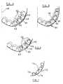
- the drill bitcomprises a bit body 10 having a leading face formed with six blades extending outwardly away from the axis of the bit body towards the gauge region.
- the bladescomprise three longer primary blades 12 alternately spaced with three shorter secondary blades 14. Between adjacent blades there are defined fluid channels 16.
- each of the primary blades 12Extending side by side along each of the primary blades 12 is a plurality of primary cutters 18 and extending along each of the secondary blades 14 is a plurality of secondary cutters 20.
- the precise nature of the cuttersdoes not form a part of the present invention and they may be of any appropriate type.
- theymay comprise circular preformed cutting elements brazed to cylindrical carriers which are imbedded or otherwise mounted in the blades, the cutting elements each comprising a preformed compact having a polycrystalline diamond front cutting table bonded to a tungsten carbide substrate, the compact being brazed to a cylindrical tungsten carbide carrier.
- substrate of the preformed compactmay itself be of sufficient length to be mounted directly in the blade, the additional carrier then being omitted.
- the secondary cutters 20may be of the same type as the primary cutters 18 or the primary and secondary cutters may be of different types.
- Inner nozzles 22are mounted in the surface of the bit body and are located in a central region of the bit body, fairly close to the axis of rotation of the drill bit. Each inner nozzle 22 is so located that it can deliver drilling fluid to two or more of the channels 16, but is so orientated that it primarily delivers drilling fluid outwardly along a channel 16 on the leading side of one of the three primary blades 12.
- outer nozzles 24are located at the outer extremity of each channel on the leading side of each secondary blade 14.
- the outer nozzlesare orientated to direct drilling fluid inwardly along their respective channels towards the centre of the drill bit, such inwardly flowing drilling fluid becoming entrained with the drilling fluid from the associated inner nozzle 22 so as to flow outwardly to the gauge region again along the adjacent channel. All the nozzles communicate with a central axial passage (not shown) in the shank of the bit to which drilling fluid is supplied under pressure downwardly through the drill string in known manner.
- the outer extremities of the blades 12, 14are formed with kickers 26 which provide part-cylindrical bearing surfaces which, in use, bear against the surrounding wall of the bore hole and stabilise the bit in the bore hole.
- Abrasion-resistant bearing elements(not shown), of any suitable known form, are imbedded in the bearing surfaces.
- Each of the channels 16 between the bladesleads to a respective junk slot 28.
- the junk slotsextend upwardly between the kickers 26, so that drilling fluid flowing outwardly along each channel passes into the associated junk slot and flows upwardly, between the bit body and the surrounding formation, into the annulus between the drill string and the wall of the bore hole.
- Each of the secondary blades 14is associated with the immediately preceding primary blade 12. In other arrangements, however, the associated primary and secondary blades need not be immediately adjacent one another but may be in any relative positions on the leading face of the bit.
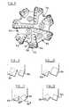
- Figure 3is a diagrammatic half section through the leading end of the drill bit showing one possible arrangement of primary cutters (shown in solid line) along their primary blade and also (in dotted lines) the corresponding positions, with respect to the bit axis, of the associated secondary cutters.
- the secondary cuttersmay be in any circumferential position on the drill bit relative to the primary cutters.
- the primary bladehas mounted thereon six primary cutters 30 which are all of substantially the same size and a smaller outermost primary cutter 32 at the gauge.
- the primary cuttersare spaced substantially equally apart along the length of the primary blade.
- the cutting edges of the primary cuttersdefine a primary cutting profile indicated diagrammatically at 34.
- the secondary cutters 36, 38comprise four cutters which are substantially similar in size and type to the primary cutters 30 and a single smaller outermost secondary cutter 38.
- each secondary cutter 36, 38is disposed at a position, with respect to the bit axis, which is intermediate the positions of two adjacent primary cutters, i.e. for each secondary cutter the cutter which is next closest to the bit axis and the cutter which is next furthest from the bit axis are both primary cutters.
- the secondary cuttersdefine a secondary cutting profile, indicated in solid line at 40 in Figure 3, which is spaced inwardly of the primary cutting profile 34.
- the primary cutterswill cut grooves in the formation leaving upstanding kerfs between the grooves, and the top of the kerfs will then be removed by the following secondary cutters. Since the secondary cutters are set to define a lower cutting profile, drilling fluid delivered through the inner and outer nozzles 22, 24 can more easily flow over the secondary blades 14 and between the secondary cutters on the blades, so as to prevent the balling of cuttings in this region.
- the secondary cutters 36will take over a greater proportion of the cutting action and the profile of the bottom of the hole will become smoother as the primary cutting profile 34 moves inwardly closer to the secondary cutting profile 40.
- the secondary cutters 36, 38could be set even further inwardly with respect to the primary cutters so as to define a more inward cutting profile as indicated in dotted line at 42.
- Figure 3shows an arrangement where the distance between the primary cutting profile 44 and the secondary profile 46 decreases with distance from the central axis 48 of the drill bit.
- the outer secondary cutters 50are displaced outwardly with respect to the primary cutters 52, the displacement increasing with distance from the bit axis 48.
- Figure 5shows an arrangement where the distance between the primary cutting profile 54 and secondary profile 56 increases with distance from the bit axis. This arrangement is otherwise generally similar to that of Figure 3 in that each secondary cutter 58 is disposed at a location intermediate to primary cutters 60 on its associated primary blade.
- Figure 6also shows an arrangement where the distance between the primary cutting profile 62 and secondary profile 64 decreases with distance from the bit axis. In this arrangement, however, the secondary cutters 66 are smaller in diameter than the primary cutters 68. As will be seen from Figure 6, the overlap between the secondary cutters and the primary cutters varies along the two blades.
- Figure 7shows an arrangement of secondary cutters only, defining a secondary cutting profile 70, where the secondary cutters comprise larger cutters 72 alternating with smaller cutters 74. It is not necessary that all secondary cutters (or indeed all primary cutters) be on the same cutting profile and Figure 7 shows an arrangement where one of the smaller cutters 76 on a secondary blade has a cutting edge spaced inwardly of the secondary cutting profile 70.
- the primary cutters on the primary bladesmay have a similar arrangement.
- At least the majority, and preferably all, of the primary cuttersare located at different distances away from the bit axis, and at least he majority of the secondary cutters are located at different distances away from the axis, as compared to the primary cutters, so that, as may be seen from the drawings, none of such secondary cutters then tracks a primary cutter.
- Arrangementsare also possible where all of the secondary cutters are located at different distances from the bit axis, as compared to the primary cutters, so that no secondary cutter tracks a primary cutter.
- the primary cuttersmay be of the same size, or larger or smaller, than the secondary cutters.
- the primary cuttersmay also be arranged at different back rake angles from the secondary cutters, and the back rake angle of the primary cutters may be greater or less than the back rake angle of the secondary cutters.
- FIG. 1 and 2the primary cutters are mounted on primary blades and the secondary cutters are mounted on separate secondary blades spaced circumferentially from the primary blades.
- Figure 8shows an alternative construction where the secondary cutters are mounted on the same blades as the primary cutters.
- the drill bitcomprises a bit body 80 having a leading face formed with seven blades 82 extending outwardly away from the axis of the bit towards the gauge region. Between adjacent blades there are defined fluid channels 84.
- each blade 82Extending side-by-side along the leading edge of each blade 82 is a plurality of primary cutters 86.
- a diamond impregnated abrasion element 90is also mounted in the blade outwardly of the secondary cutters 88.
- both the primary and secondary cuttersmay comprise circular preformed cutting elements which are mounted in sockets in the blades, the cutting elements each comprising a preformed compact having a polycrystalline diamond front cutting table bonded to a tungsten carbide substrate.
- the secondary cutters 88may be of the same type as the primary cutters 86 or the primary and secondary cutters may be of different types.
- Inner nozzles 92are mounted in the surface of the bit body fairly close to the axis of rotation of the bit, and outer nozzles 94 are located at the outer extremities of some of the fluid channels 84.
- the primary cutters 86are located at different distances from the bit axis so that, as the bit rotates, the cutting edges of the primary cutters define a cutting profile which extends over the whole of the bottom of the borehole being drilled.
- the secondary cutters 88are located at different distances away from the bit axis, as compared to the primary cutters 86, so that none of the secondary cutters 88 tracks a primary cutter.
- the secondary cuttersmay, in accordance with one aspect of the present invention, define a secondary cutting profile which is disposed inwardly, with respect to the bit body, of the primary cutting profile defined by the primary cutters 86.
- the drill bit of Figure 8may also be constructed so that the cutting edges of the secondary cutters 88 lie on the same profile as the cutting edges of the primary cutters 86.
- Figures 9 to 12show diagrammatic sections through adjacent primary and secondary cutters on a drill bit of the kind shown in Figure 8.
- the secondary cuttersare shown lying in the same plane as the primary cutters but, in practice, in accordance with the present invention, the secondary cutters will be mounted at a different distance from the axis of rotation of the drill bit so that the secondary cutter does not track the primary cutter.
- FIG. 9there is shown a secondary cutter 88 which is of larger diameter than the primary cutter 86 and is disposed at the same back rake angle.
- Figure 10shows an arrangement where the primary cutter 86 is of greater diameter than the secondary cutter 88.
- the primary cutter 86 and secondary cutter 88are both of the same size, but the front cutting face 88a of the secondary cutter is disposed at a greater back rake angle than the front cutting face 86a of the associated primary cutter 86.
- Figure 12shows the opposite arrangement where the back rake angle of the primary cutter 86 is greater than the back rake angle of the secondary cutter 88.
- the cutting edges of both the primary and secondary cutterslie on substantially the same profile.
- the cutting edges of the secondary cutters 88may define a cutting profile which is disposed inwardly of the cutting profile defined by the cutting edges of the primary cutters.
Landscapes
- Engineering & Computer Science (AREA)
- Life Sciences & Earth Sciences (AREA)
- Geology (AREA)
- Mining & Mineral Resources (AREA)
- Mechanical Engineering (AREA)
- Physics & Mathematics (AREA)
- Environmental & Geological Engineering (AREA)
- Fluid Mechanics (AREA)
- General Life Sciences & Earth Sciences (AREA)
- Geochemistry & Mineralogy (AREA)
- Drilling Tools (AREA)
- Earth Drilling (AREA)
Description
- The invention relates to rotary drill bits for use in drilling holes in subsurfaceformations, and of the kind comprising a bit body having a shank for connection to a drillstring, a plurality of circumferentially spaced blades on the bit body extending outwardlyaway from the central axis of rotation of the bit, and a plurality of cutting elementsmounted along each blade.
- The invention is particularly, but not exclusively, applicable to drill bits in whichsome or all of the cutters are preformed (PDC) cutters each formed, at least in part, frompolycrystalline diamond. One common form of cutter comprises a tablet, usually circularor part-circular, made up of a superhard table of polycrystalline diamond, providing thefront cutting face of the element, bonded to a substrate which is usually of cementedtungsten carbide.
- The bit body may be machined from solid metal, usually steel, or may bemoulded using a powder metallurgy process in which tungsten carbide powder isinfiltrated with a metal alloy binder in a furnace so as to form a hard matrix.
- The cutters on the drill bit have cutting edges which, together, define an overallcutting profile which defines the surface shape of the bottom of the bore hole which thebit drills. Preferably the cutting profile is substantially continuous over the leading faceof the bit so as to form a comparatively smooth bottom hole profile.
- In some drill bits of the above kind, there are associated with at least some of thecutters further secondary cutters each of which is circumferentially spaced from anassociated primary cutter but is disposed at substantially the same distance from the axis of the bit as the associated primary cutter, so as to "track" the primary cutter as the bitrotates. That is to say, the secondary cutter follows the groove cut in the formation byits associated primary cutter as the bit rotates. In such arrangements the secondarycutters may be so disposed that their cutting edges lie inwardly of the profile defined bythe primary cutters so that each secondary cutter serves as a back-up to its associatedprimary cutter and only performs an effective cutting action on the formation should theprimary cutter become damaged or worn so that it is no longer effective.
- US 5531281 describes an arrangement having primary and secondary cuttersarranged in a non-tracking formation and designed to allow the cutting of annulargrooves in the formation being drilled serving to stabilise the bit against vibration.EP 0710765 describes a tracking bit including primary and secondary cutters, thesecondary cutters being positioned to follow tracks cut by a preceding primary cutter.US 5549171 describes a drill bit having primary and secondary cutters positioned atvarious back rake angles. EP 0575198 discloses a tracking cutter in which a range ofcutter sizes are used on both the primary blade and the secondary blade.
- According to the invention there is provided a rotary drill bit for drilling holesin subsurface formations, comprising a bit body having a shank for connection to a drillstring, a plurality of circumferentially spaced blades on the bit body extending outwardlyaway from the central axis of rotation of the bit, and a plurality of cutters mounted alongeach blade, at least the majority of which cutters are located at different distances awayfrom the bit axis than any other cutter, said cutters including primary cutters havingcutting edges which define a primary cutting profile and secondary cutters having cutting edges which define a secondary cutting profile which is disposed inwardly of theprimary cutting profile with respect to the bit body, wherein the secondary cutters areof different sizes.
- The arrangement according to the invention differs significantly from the priorart mentioned above in that at least the majority of the secondary cutters, instead oftracking associated primary cutters, are located at different positions as compared to theprimary cutters so that no tracking occurs. The secondary cutters will thus make somecontribution to the cutting of the formation at all times, the contribution increasing asthe primary cutters wear. When the drill bit is new, and the primary cutters performmost of the cutting action, a high rate of penetration may be achieved particularly insofter formations. At the same time, however, the fact that the secondary cutters lie ona lower profile may ficilitate the flow of drilling fluid between the secondary cutters andacross the secondary blades, thereby reducing the tendency for bit "balling" to occur,where soft sticky formation accumulates on the surface of the bit around the cutters.
- As drilling progresses, and firmer formations are met, the primary cuttersexperience wear and the secondary cutters begin to make a bigger contribution to thedrilling action resulting in a smoother bottom hole profile. This may improve thesteerability of the drill bit when used with a steering system.
- The primary cutters may be mounted on primary blades and at least some of thesecondary cutters mounted on separate secondary blades. The primary blades andsecondary blades may be spaced alternately apart around the axis of rotation of the bit.
- There may be fewer secondary cutters on each secondary blade than there are primary cutters on each primary blade. The primary blades may be longer than thesecondary blades so as to extend into said central region of the bit body.
- Each secondary blade may be associated with a particular primary blade, eachsecondary cutter then being located at a position, with respect to the bit axis, which isintermediate the positions of two adjacent primary cutters on its associated primaryblade. In this case each secondary blade may be the next adjacent blade rearwardly ofits associated primary blade with respect to the normal direction of rotation of the drillbit.
- In another embodiment of the invention at least some of said secondary cuttersmay be mounted on the same blades as at least some of the primary cutters. Forexample, the secondary cutters may be disposed rearwardly of the primary cutters on thesame blade, with respect to the normal direction of forward rotation of the drill bit. Thesecondary cutters may be mounted on an outer region of the blade.
- The number of secondary cutters may be less than the number of primary cutterson the same blade. For example, the bit body may include a central region around theaxis of rotation of the bit where only primary cutters are mounted.
- The secondary cutters may include cutters which are smaller or larger than atleast the majority of the primary cutters. At least the majority of the secondary cuttersmay be smaller or larger than at least the majority of the primary cutters.
- The secondary cutters are are of different sizes. For example, larger secondarycutters may be arranged alternately with smaller secondary cutters along the length ofa blade.
- In any of the above arrangements at least some of the secondary cutters may beset at different back rake angles from at least some of the primary cutters. They may beset at a greater or smaller back rake angle than the primary cutters.
- In any of the above arrangements also, the distance between the primary cuttingprofile and the secondary cutting profile may substantially constant over the surface ofthe bit, or may increase or decrease with distance from the axis of rotation of the bit.
- The bit body may be provided with a plurality of nozzles for the delivery ofdrilling fluid to the surface of the bit for cooling and cleaning the cutters, the nozzlesincluding inner nozzles each of which is located to direct drilling fluid outwardly alongthe primary cutters on a primary blade, and outer nozzles each of which is located todirect drilling fluid inwardly along the secondary cutters on a secondary blade.
- The following is a more detailed description of embodiments of the invention,by way of example, reference being made to the accompanying drawings in which:
- Figure 1 is a perspective view of a PDC drill bit in accordance with the presentinvention;
- Figure 2 is an end view of the drill bit shown in Figure 1;
- Figure 3 is a diagrammatic representation of one arrangement of primary andsecondary cutters on the drill bit;
- Figures 4 to 7 are similar views to Figure 3 of alternative cutter arrangements;
- Figure 8 is an end view of another form of PDC drill bit in accordance with thepresent invention; and
- Figures 9 to 12 are diagrammatic sections through a blade in a drill bit of thekind shown in Figure 8, showing alternative configurations of primary and secondarycutters.
- Referring to Figures 1 and 2, the drill bit comprises a
bit body 10 having aleading face formed with six blades extending outwardly away from the axis of the bitbody towards the gauge region. The blades comprise three longerprimary blades 12alternately spaced with three shortersecondary blades 14. Between adjacent bladesthere are definedfluid channels 16. - Extending side by side along each of the
primary blades 12 is a plurality ofprimary cutters 18 and extending along each of thesecondary blades 14 is a plurality ofsecondary cutters 20. The precise nature of the cutters does not form a part of thepresent invention and they may be of any appropriate type. For example, as shown, theymay comprise circular preformed cutting elements brazed to cylindrical carriers whichare imbedded or otherwise mounted in the blades, the cutting elements each comprisinga preformed compact having a polycrystalline diamond front cutting table bonded to atungsten carbide substrate, the compact being brazed to a cylindrical tungsten carbidecarrier. Alternatively, substrate of the preformed compact may itself be of sufficientlength to be mounted directly in the blade, the additional carrier then being omitted. - The
secondary cutters 20 may be of the same type as theprimary cutters 18 or the primary and secondary cutters may be of different types. Inner nozzles 22 are mounted in the surface of the bit body and are located in acentral region of the bit body, fairly close to the axis of rotation of the drill bit. Eachinner nozzle 22 is so located that it can deliver drilling fluid to two or more of thechannels 16, but is so orientated that it primarily delivers drilling fluid outwardly alongachannel 16 on the leading side of one of the threeprimary blades 12.- In addition,
outer nozzles 24 are located at the outer extremity of each channelon the leading side of eachsecondary blade 14. The outer nozzles are orientated todirect drilling fluid inwardly along their respective channels towards the centre of thedrill bit, such inwardly flowing drilling fluid becoming entrained with the drilling fluidfrom the associatedinner nozzle 22 so as to flow outwardly to the gauge region againalong the adjacent channel. All the nozzles communicate with a central axial passage(not shown) in the shank of the bit to which drilling fluid is supplied under pressuredownwardly through the drill string in known manner. - The outer extremities of the
blades kickers 26 whichprovide part-cylindrical bearing surfaces which, in use, bear against the surrounding wallof the bore hole and stabilise the bit in the bore hole. Abrasion-resistant bearingelements (not shown), of any suitable known form, are imbedded in the bearing surfaces. - Each of the
channels 16 between the blades leads to arespective junk slot 28.The junk slots extend upwardly between thekickers 26, so that drilling fluid flowingoutwardly along each channel passes into the associated junk slot and flows upwardly,between the bit body and the surrounding formation, into the annulus between the drill string and the wall of the bore hole. - Each of the
secondary blades 14 is associated with the immediately precedingprimary blade 12. In other arrangements, however, the associated primary andsecondary blades need not be immediately adjacent one another but may be in anyrelative positions on the leading face of the bit. - Figure 3 is a diagrammatic half section through the leading end of the drill bitshowing one possible arrangement of primary cutters (shown in solid line) along theirprimary blade and also (in dotted lines) the corresponding positions, with respect to thebit axis, of the associated secondary cutters. As previously explained, the secondarycutters may be in any circumferential position on the drill bit relative to the primarycutters.
- In the arrangement shown in Figure 3, the primary blade has mounted thereonsix
primary cutters 30 which are all of substantially the same size and a smalleroutermostprimary cutter 32 at the gauge. The primary cutters are spaced substantiallyequally apart along the length of the primary blade. The cutting edges of the primarycutters define a primary cutting profile indicated diagrammatically at 34. - The
secondary cutters primary cutters 30 and a single smaller outermostsecondary cutter 38. As may be seen from Figure 3, eachsecondary cutter - It will thus be seen that, when the drill bit is new, the primary cutters will cutgrooves in the formation leaving upstanding kerfs between the grooves, and the top ofthe kerfs will then be removed by the following secondary cutters. Since the secondarycutters are set to define a lower cutting profile, drilling fluid delivered through the innerand
outer nozzles secondary blades 14 and betweenthe secondary cutters on the blades, so as to prevent the balling of cuttings in this region. - As the
primary cutters 30 wear, or become damaged, thesecondary cutters 36will take over a greater proportion of the cutting action and the profile of the bottom ofthe hole will become smoother as the primary cutting profile 34 moves inwardly closerto thesecondary cutting profile 40. - In the arrangement of Figure 3, the
secondary cutters - In the arrangement of Figure 3, the spacing between the primary cutting profile34 and
secondary cutting profile 40 is substantially constant over the face of the drill bit.Figure 4 shows an arrangement where the distance between theprimary cutting profile 44 and thesecondary profile 46 decreases with distance from thecentral axis 48 of thedrill bit. - In this case, the outer
secondary cutters 50 are displaced outwardly with respectto theprimary cutters 52, the displacement increasing with distance from thebit axis 48. - Figure 5 shows an arrangement where the distance between the
primary cuttingprofile 54 andsecondary profile 56 increases with distance from the bit axis. Thisarrangement is otherwise generally similar to that of Figure 3 in that eachsecondarycutter 58 is disposed at a location intermediate toprimary cutters 60 on its associatedprimary blade. - Figure 6 also shows an arrangement where the distance between the
primarycutting profile 62 andsecondary profile 64 decreases with distance from the bit axis. Inthis arrangement, however, the secondary cutters 66 are smaller in diameter than theprimary cutters 68. As will be seen from Figure 6, the overlap between the secondarycutters and the primary cutters varies along the two blades. - Figure 7 shows an arrangement of secondary cutters only, defining a
secondarycutting profile 70, where the secondary cutters compriselarger cutters 72 alternatingwithsmaller cutters 74. It is not necessary that all secondary cutters (or indeed allprimary cutters) be on the same cutting profile and Figure 7 shows an arrangementwhere one of thesmaller cutters 76 on a secondary blade has a cutting edge spacedinwardly of thesecondary cutting profile 70. The primary cutters on the primary bladesmay have a similar arrangement. - In all of the above described arrangements at least the majority, and preferablyall, of the primary cutters are located at different distances away from the bit axis, andat least he majority of the secondary cutters are located at different distances away fromthe axis, as compared to the primary cutters, so that, as may be seen from the drawings,none of such secondary cutters then tracks a primary cutter. Arrangements are also possible where all of the secondary cutters are located at different distances from the bitaxis, as compared to the primary cutters, so that no secondary cutter tracks a primarycutter.
- In any of the above arrangements the primary cutters may be of the same size,or larger or smaller, than the secondary cutters. The primary cutters may also bearranged at different back rake angles from the secondary cutters, and the back rakeangle of the primary cutters may be greater or less than the back rake angle of thesecondary cutters.
- In the drill bit shown in Figures 1 and 2 the primary cutters are mounted onprimary blades and the secondary cutters are mounted on separate secondary bladesspaced circumferentially from the primary blades. Figure 8 shows an alternativeconstruction where the secondary cutters are mounted on the same blades as the primarycutters.
- Referring to Figure 8, the drill bit comprises a
bit body 80 having a leading faceformed with sevenblades 82 extending outwardly away from the axis of the bit towardsthe gauge region. Between adjacent blades there are definedfluid channels 84. - Extending side-by-side along the leading edge of each
blade 82 is a plurality ofprimary cutters 86. On each blade twosecondary cutters 88 are mounted rearwardly oftheprimary cutters 86 at the outer end of theblade 82. A diamond impregnatedabrasion element 90 is also mounted in the blade outwardly of thesecondary cutters 88. - As in the previously described arrangements, both the primary and secondarycutters may comprise circular preformed cutting elements which are mounted in sockets in the blades, the cutting elements each comprising a preformed compact having apolycrystalline diamond front cutting table bonded to a tungsten carbide substrate. The
secondary cutters 88 may be of the same type as theprimary cutters 86 or the primaryand secondary cutters may be of different types. Inner nozzles 92 are mounted in the surface of the bit body fairly close to the axisof rotation of the bit, andouter nozzles 94 are located at the outer extremities of someof thefluid channels 84.- The
primary cutters 86 are located at different distances from the bit axis so that,as the bit rotates, the cutting edges of the primary cutters define a cutting profile whichextends over the whole of the bottom of the borehole being drilled. Thesecondarycutters 88 are located at different distances away from the bit axis, as compared to theprimary cutters 86, so that none of thesecondary cutters 88 tracks a primary cutter. Thesecondary cutters may, in accordance with one aspect of the present invention, definea secondary cutting profile which is disposed inwardly, with respect to the bit body, ofthe primary cutting profile defined by theprimary cutters 86. However, the drill bit ofFigure 8 may also be constructed so that the cutting edges of thesecondary cutters 88lie on the same profile as the cutting edges of theprimary cutters 86. - Figures 9 to 12 show diagrammatic sections through adjacent primary andsecondary cutters on a drill bit of the kind shown in Figure 8. For convenience thesecondary cutters are shown lying in the same plane as the primary cutters but, inpractice, in accordance with the present invention, the secondary cutters will be mountedat a different distance from the axis of rotation of the drill bit so that the secondary cutter does not track the primary cutter.
- Referring to Figure 9, there is shown a
secondary cutter 88 which is of largerdiameter than theprimary cutter 86 and is disposed at the same back rake angle. Figure10 shows an arrangement where theprimary cutter 86 is of greater diameter than thesecondary cutter 88. - In the arrangement of Figure 11 the
primary cutter 86 andsecondary cutter 88are both of the same size, but the front cutting face 88a of the secondary cutter isdisposed at a greater back rake angle than the front cutting face 86a of the associatedprimary cutter 86. Figure 12 shows the opposite arrangement where the back rake angleof theprimary cutter 86 is greater than the back rake angle of thesecondary cutter 88. - In all of the arrangements shown in Figures 9-12 the cutting edges of both theprimary and secondary cutters lie on substantially the same profile. However, aspreviously explained, in accordance with one aspect of the present invention, the cuttingedges of the
secondary cutters 88 may define a cutting profile which is disposed inwardlyof the cutting profile defined by the cutting edges of the primary cutters.
Claims (25)
- A rotary drill bit for drilling holes in subsurface formations, comprising a bit body(10) having a shank for connection to a drill string, a plurality of circumferentially spacedblades (12, 14) on the bit body (10) extending outwardly away from the central axis ofrotation ofthe bit, and a plurality of cutters (18, 20) mounted along each blade (12, 14),at least the majority of which cutters (18, 20) are located at a different distance awayfrom the bit axis than any other cutter (18, 20), said cutters including primary cutters(18) having cutting edges which define a primary cutting profile (34) and secondarycutters (20) having cutting edges which define a secondary cutting profile (40) which isdisposed inwardly of the primary cutting profile (34) with respect to the bit body, andcharacterised in that the secondary cutters (36, 38) are of different sizes.
- A drill bit according to Claim 1, wherein the primary cutters (18) are mountedon primary blades (12) and at least some of the secondary cutters (20) are mounted onseparate secondary blades (14).
- A drill bit according to Claim 2, wherein the primary blades (12) and secondaryblades (13) are spaced alternately apart around the axis of rotation of the bit.
- A drill bit according to Claim 2 or Claim 3, wherein there are fewer secondarycutters (20) on each secondary blade (14) than there are primary cutters (18) on eachprimary blade (12).
- A drill bit according to any of Claims 2 to 4, wherein the primary blades (12) arelonger than the secondary blades (14) so as to extend into said central region of the bitbody (10).
- A drill bit according to any of the preceding claims, wherein the cutter which is next closest to the bit axis than each secondary cutter (20) and the cutter which is nextfurthest from the bit axis than each secondary cutter (20) are both primary cutters (18).
- A drill bit according to Claim 6, wherein said next closest and next furthestprimary cutters (18) lie on the same blade.
- A drill bit according to any of Claims 2 to 5, wherein each secondary blade (14)is associated with a particular primary blade (12), each secondary cutter (20) then beinglocated at a position, with respect to the bit axis, which is intermediate the positions oftwo adjacent primary cutters (18)on its associated primary blade (12).
- A drill bit according to Claim 8, wherein each secondary blade (14) is the nextadjacent blade rearwardly of its associated primary blade (12) with respect to the normaldirection of rotation of the drill bit.
- A drill bit according to any of the preceding claims, wherein at least some of saidsecondary cutters (20) are mounted on the same blades as at least some of the primarycutters (18).
- A drill bit according to Claim 10, wherein said secondary cutters (20) aredisposed rearwardly of the primary cutters (18) on the same blade, with respect to thenormal direction of forward rotation of the drill bit.
- A drill bit according to Claim 10 or Claim 11, wherein said secondary cutters(20) are mounted on an outer region of the blade.
- A drill bit according to any of Claims 10 to 12, wherein the number of secondarycutters (20) is less than the number of primary cutters (18) on the same blade.
- A drill bit according to any of the preceding claims, wherein the bit body (10)includes a central region around the axis of rotation of the bit where only primary cutters(18) are mounted.
- A drill bit according to any of the preceding claims, wherein the secondarycutters (20) include cutters which are smaller than at least the majority of the primarycutters (18).
- A drill bit according to Claim 15, wherein at least the majority of the secondarycutters (20) are smaller than at least the majority of the primary cutters (18).
- A drill bit according to Claim 15, wherein at least the majority of the secondarycutters (20) are larger than at least the majority of the primary cutters (18).
- A drill bit according to Claim 1, wherein larger secondary cutters (20) arearranged alternately with smaller secondary cutters (20) along the length of a blade.
- A drill bit according to any of the preceding claims, wherein at least some of thesecondary cutters (20) are set at different back rake angles from at least some of theprimary cutters (18).
- A drill bit according to Claim 19, wherein at least some of the secondary cutters(20) are set at a greater back rake angle than at least some of the primary cutters (18).
- A drill bit according to Claim 19, wherein at least some of the secondary cutters(20) are set at a smaller back rake angle than at least some of the primary cutters (18).
- A drill bit according to any of the preceding claims, wherein the distance betweenthe primary cutting profile (34) and the secondary cutting profile (40) is substantiallyconstant over the surface of the bit.
- A drill bit according to any of the preceding Claims 1 to 21, wherein the distancebetween the cutting profiles (34, 40) increases with distance from the axis of rotation ofthe bit.
- A drill bit according to any of the preceding Claims 1 to 21, wherein the distancebetween the cutting profiles (34, 40) decreases with distance from the axis of rotation of the bit.
- A drill bit according to any of the preceding claims, wherein the bit body (10) isprovided with a plurality of nozzles (22) for the delivery of drilling fluid to the surfaceof the bit for cooling and cleaning the cutters, the nozzles (22) including inner nozzleseach of which is located to direct drilling fluid outwardly along the primary cutters (18)on a primary blade, and outer nozzles each of which is located to direct drilling fluidinwardly along the secondary cutters (20) on a secondary blade.
Applications Claiming Priority (2)
| Application Number | Priority Date | Filing Date | Title |
|---|---|---|---|
| GB9712342 | 1997-06-14 | ||
| GBGB9712342.6AGB9712342D0 (en) | 1997-06-14 | 1997-06-14 | Improvements in or relating to rotary drill bits |
Publications (2)
| Publication Number | Publication Date |
|---|---|
| EP0884449A1 EP0884449A1 (en) | 1998-12-16 |
| EP0884449B1true EP0884449B1 (en) | 2002-08-28 |
Family
ID=10814114
Family Applications (1)
| Application Number | Title | Priority Date | Filing Date |
|---|---|---|---|
| EP98304500AExpired - LifetimeEP0884449B1 (en) | 1997-06-14 | 1998-06-08 | Rotary drill bits |
Country Status (4)
| Country | Link |
|---|---|
| US (1) | US6123161A (en) |
| EP (1) | EP0884449B1 (en) |
| DE (1) | DE69807398T2 (en) |
| GB (2) | GB9712342D0 (en) |
Families Citing this family (52)
| Publication number | Priority date | Publication date | Assignee | Title |
|---|---|---|---|---|
| US6460631B2 (en) | 1999-08-26 | 2002-10-08 | Baker Hughes Incorporated | Drill bits with reduced exposure of cutters |
| US6298930B1 (en)* | 1999-08-26 | 2001-10-09 | Baker Hughes Incorporated | Drill bits with controlled cutter loading and depth of cut |
| ZA200005048B (en) | 1999-09-24 | 2002-02-14 | Varel International Inc | Improved rotary cone bit for cutting removal. |
| DE60140617D1 (en)* | 2000-09-20 | 2010-01-07 | Camco Int Uk Ltd | POLYCRYSTALLINE DIAMOND WITH A SURFACE ENRICHED ON CATALYST MATERIAL |
| US6408958B1 (en) | 2000-10-23 | 2002-06-25 | Baker Hughes Incorporated | Superabrasive cutting assemblies including cutters of varying orientations and drill bits so equipped |
| US6536543B2 (en)* | 2000-12-06 | 2003-03-25 | Baker Hughes Incorporated | Rotary drill bits exhibiting sequences of substantially continuously variable cutter backrake angles |
| US6568492B2 (en) | 2001-03-02 | 2003-05-27 | Varel International, Inc. | Drag-type casing mill/drill bit |
| US6659199B2 (en) | 2001-08-13 | 2003-12-09 | Baker Hughes Incorporated | Bearing elements for drill bits, drill bits so equipped, and method of drilling |
| US6615934B2 (en)* | 2001-08-15 | 2003-09-09 | Smith International, Inc. | PDC drill bit having cutting structure adapted to improve high speed drilling performance |
| US7360608B2 (en)* | 2004-09-09 | 2008-04-22 | Baker Hughes Incorporated | Rotary drill bits including at least one substantially helically extending feature and methods of operation |
| US20070078632A1 (en)* | 2005-08-05 | 2007-04-05 | Smith International, Inc. | Stress balanced cutting structure |
| US7860693B2 (en)* | 2005-08-08 | 2010-12-28 | Halliburton Energy Services, Inc. | Methods and systems for designing and/or selecting drilling equipment using predictions of rotary drill bit walk |
| CA2625012C (en) | 2005-08-08 | 2016-05-03 | Halliburton Energy Services, Inc. | Methods and systems for design and/or selection of drilling equipment based on wellbore drilling simulations |
| GB0521693D0 (en)* | 2005-10-25 | 2005-11-30 | Reedhycalog Uk Ltd | Representation of whirl in fixed cutter drill bits |
| US8141665B2 (en) | 2005-12-14 | 2012-03-27 | Baker Hughes Incorporated | Drill bits with bearing elements for reducing exposure of cutters |
| US7866413B2 (en)* | 2006-04-14 | 2011-01-11 | Baker Hughes Incorporated | Methods for designing and fabricating earth-boring rotary drill bits having predictable walk characteristics and drill bits configured to exhibit predicted walk characteristics |
| US7677333B2 (en)* | 2006-04-18 | 2010-03-16 | Varel International Ind., L.P. | Drill bit with multiple cutter geometries |
| US20070267227A1 (en)* | 2006-05-08 | 2007-11-22 | Varel International Ind., L.P. | Drill bit with staged durability, stability and rop characteristics |
| US20070261890A1 (en)* | 2006-05-10 | 2007-11-15 | Smith International, Inc. | Fixed Cutter Bit With Centrally Positioned Backup Cutter Elements |
| GB2453875C (en)* | 2006-10-02 | 2009-09-16 | Smith International | Drill bits with dropping tendencies |
| US9359825B2 (en)* | 2006-12-07 | 2016-06-07 | Baker Hughes Incorporated | Cutting element placement on a fixed cutter drill bit to reduce diamond table fracture |
| US7896106B2 (en)* | 2006-12-07 | 2011-03-01 | Baker Hughes Incorporated | Rotary drag bits having a pilot cutter configuraton and method to pre-fracture subterranean formations therewith |
| RU2009131831A (en)* | 2007-01-25 | 2011-02-27 | Бейкер Хьюз Инкорпорейтед (Us) | ROTARY DRILLING CHISEL FOR ROTARY DRILLING |
| US8905163B2 (en)* | 2007-03-27 | 2014-12-09 | Halliburton Energy Services, Inc. | Rotary drill bit with improved steerability and reduced wear |
| US7703557B2 (en)* | 2007-06-11 | 2010-04-27 | Smith International, Inc. | Fixed cutter bit with backup cutter elements on primary blades |
| US7814997B2 (en) | 2007-06-14 | 2010-10-19 | Baker Hughes Incorporated | Interchangeable bearing blocks for drill bits, and drill bits including same |
| US9016407B2 (en) | 2007-12-07 | 2015-04-28 | Smith International, Inc. | Drill bit cutting structure and methods to maximize depth-of-cut for weight on bit applied |
| AU2008338627B2 (en) | 2007-12-14 | 2014-04-10 | Halliburton Energy Services, Inc. | Methods and systems to predict rotary drill bit walk and to design rotary drill bits and other downhole tools |
| WO2009146078A1 (en) | 2008-04-01 | 2009-12-03 | Smith International, Inc. | Fixed cutter bit with backup cutter elements on secondary blades |
| GB2460096B (en) | 2008-06-27 | 2010-04-07 | Wajid Rasheed | Expansion and calliper tool |
| US20100025121A1 (en)* | 2008-07-30 | 2010-02-04 | Thorsten Schwefe | Earth boring drill bits with using opposed kerfing for cutters |
| US20100089661A1 (en)* | 2008-10-13 | 2010-04-15 | Baker Hughes Incorporated | Drill bit with continuously sharp edge cutting elements |
| US8020641B2 (en)* | 2008-10-13 | 2011-09-20 | Baker Hughes Incorporated | Drill bit with continuously sharp edge cutting elements |
| US8720609B2 (en)* | 2008-10-13 | 2014-05-13 | Baker Hughes Incorporated | Drill bit with continuously sharp edge cutting elements |
| US20100089658A1 (en)* | 2008-10-13 | 2010-04-15 | Baker Hughes Incorporated | Drill bit with continuously sharp edge cutting elements |
| US8943663B2 (en) | 2009-04-15 | 2015-02-03 | Baker Hughes Incorporated | Methods of forming and repairing cutting element pockets in earth-boring tools with depth-of-cut control features, and tools and structures formed by such methods |
| US20100276200A1 (en)* | 2009-04-30 | 2010-11-04 | Baker Hughes Incorporated | Bearing blocks for drill bits, drill bit assemblies including bearing blocks and related methods |
| US8191657B2 (en)* | 2009-05-28 | 2012-06-05 | Baker Hughes Incorporated | Rotary drag bits for cutting casing and drilling subterranean formations |
| US8887839B2 (en) | 2009-06-25 | 2014-11-18 | Baker Hughes Incorporated | Drill bit for use in drilling subterranean formations |
| RU2012103935A (en) | 2009-07-08 | 2013-08-20 | Бейкер Хьюз Инкорпорейтед | CUTTING ELEMENT AND METHOD FOR ITS FORMATION |
| BR112012000535A2 (en) | 2009-07-08 | 2019-09-24 | Baker Hughes Incorporatled | cutting element for a drill bit used for drilling underground formations |
| EP2479003A3 (en) | 2009-07-27 | 2013-10-02 | Baker Hughes Incorporated | Abrasive article |
| WO2011038383A2 (en)* | 2009-09-28 | 2011-03-31 | Bake Hughes Incorporated | Earth-boring tools, methods of making earth-boring tools and methods of drilling with earth-boring tools |
| US9309723B2 (en)* | 2009-10-05 | 2016-04-12 | Baker Hughes Incorporated | Drill bits and tools for subterranean drilling, methods of manufacturing such drill bits and tools and methods of directional and off center drilling |
| GB201302379D0 (en) | 2013-01-16 | 2013-03-27 | Nov Downhole Eurasia Ltd | Drill bit |
| WO2015094221A1 (en)* | 2013-12-18 | 2015-06-25 | Halliburton Energy Services, Inc. | Cutting structure design with secondary cutter methodology |
| GB2536821B (en)* | 2013-12-26 | 2018-04-18 | Halliburton Energy Services Inc | Multilevel force balanced downhole drilling tools including cutting elements in a track-set configuration |
| CN105723046B (en)* | 2013-12-26 | 2019-08-09 | 哈利伯顿能源服务公司 | Multistage dynamic balance downhole well tool including the cutting element in stepped face configuration |
| US10344537B2 (en)* | 2016-07-28 | 2019-07-09 | Baker Hughes Incorporated | Earth-boring tools, methods of forming earth-boring tools, and methods of forming a borehole in a subterranean formation |
| CN113355996B (en)* | 2021-06-19 | 2022-03-11 | 江苏杜邦建设工程有限公司 | Highway road surface finishing device |
| CN116464392A (en)* | 2023-03-23 | 2023-07-21 | 中国石油天然气集团有限公司 | Bit cutting structure, PDC bit with multilayer cutting structure and application of PDC bit |
| WO2025015012A1 (en)* | 2023-07-10 | 2025-01-16 | Schlumberger Technology Corporation | Devices, systems, and methods of a cutting element in a bit |
Family Cites Families (14)
| Publication number | Priority date | Publication date | Assignee | Title |
|---|---|---|---|---|
| DE3039632C2 (en)* | 1980-10-21 | 1982-12-16 | Christensen, Inc., 84115 Salt Lake City, Utah | Rotary bit for deep drilling |
| DE3113109C2 (en)* | 1981-04-01 | 1983-11-17 | Christensen, Inc., 84115 Salt Lake City, Utah | Rotary drill bit for deep drilling |
| GB2241266A (en)* | 1990-02-27 | 1991-08-28 | Dresser Ind | Intersection solution method for drill bit design |
| US5244039A (en)* | 1991-10-31 | 1993-09-14 | Camco Drilling Group Ltd. | Rotary drill bits |
| US5238075A (en)* | 1992-06-19 | 1993-08-24 | Dresser Industries, Inc. | Drill bit with improved cutter sizing pattern |
| GB9314954D0 (en)* | 1993-07-16 | 1993-09-01 | Camco Drilling Group Ltd | Improvements in or relating to torary drill bits |
| US5549171A (en)* | 1994-08-10 | 1996-08-27 | Smith International, Inc. | Drill bit with performance-improving cutting structure |
| US5582261A (en)* | 1994-08-10 | 1996-12-10 | Smith International, Inc. | Drill bit having enhanced cutting structure and stabilizing features |
| US5551522A (en)* | 1994-10-12 | 1996-09-03 | Smith International, Inc. | Drill bit having stability enhancing cutting structure |
| GB2294712B (en)* | 1994-11-01 | 1998-06-24 | Camco Drilling Group Ltd | Improvements in or relating to rotary drill bits |
| GB9421924D0 (en)* | 1994-11-01 | 1994-12-21 | Camco Drilling Group Ltd | Improvements in or relating to rotary drill bits |
| US5607024A (en)* | 1995-03-07 | 1997-03-04 | Smith International, Inc. | Stability enhanced drill bit and cutting structure having zones of varying wear resistance |
| US5607025A (en)* | 1995-06-05 | 1997-03-04 | Smith International, Inc. | Drill bit and cutting structure having enhanced placement and sizing of cutters for improved bit stabilization |
| US5816346A (en)* | 1996-06-06 | 1998-10-06 | Camco International, Inc. | Rotary drill bits and methods of designing such drill bits |
- 1997
- 1997-06-14GBGBGB9712342.6Apatent/GB9712342D0/enactivePending
- 1997-12-02USUS08/982,837patent/US6123161A/ennot_activeExpired - Lifetime
- 1998
- 1998-06-08EPEP98304500Apatent/EP0884449B1/ennot_activeExpired - Lifetime
- 1998-06-08DEDE69807398Tpatent/DE69807398T2/ennot_activeExpired - Fee Related
- 1998-06-08GBGB9812114Apatent/GB2326659B/ennot_activeExpired - Lifetime
Also Published As
| Publication number | Publication date |
|---|---|
| EP0884449A1 (en) | 1998-12-16 |
| GB9712342D0 (en) | 1997-08-13 |
| GB2326659A (en) | 1998-12-30 |
| GB2326659B (en) | 2001-09-05 |
| DE69807398D1 (en) | 2002-10-02 |
| DE69807398T2 (en) | 2003-03-20 |
| US6123161A (en) | 2000-09-26 |
| GB9812114D0 (en) | 1998-08-05 |
Similar Documents
| Publication | Publication Date | Title |
|---|---|---|
| EP0884449B1 (en) | Rotary drill bits | |
| US6089336A (en) | Rotary drill bits | |
| US6062325A (en) | Rotary drill bits | |
| US10851594B2 (en) | Kerfing hybrid drill bit and other downhole cutting tools | |
| CA2605196C (en) | Drag bits with dropping tendencies and methods for making the same | |
| EP0869256B1 (en) | Rotary drill bit with gage definition region, method of manufacturing such a drill bit and method of drilling a subterranean formation | |
| EP1096103B1 (en) | Drill-out bi-center bit | |
| US5186268A (en) | Rotary drill bits | |
| US6408958B1 (en) | Superabrasive cutting assemblies including cutters of varying orientations and drill bits so equipped | |
| EP0707132B1 (en) | Rotary drill bit | |
| US5582261A (en) | Drill bit having enhanced cutting structure and stabilizing features | |
| US8061453B2 (en) | Drill bit with asymmetric gage pad configuration | |
| US5816346A (en) | Rotary drill bits and methods of designing such drill bits | |
| EP0974730B1 (en) | Rotary dag bit | |
| US20090145669A1 (en) | Drill Bit Cutting Structure and Methods to Maximize Depth-0f-Cut For Weight on Bit Applied | |
| GB2326657A (en) | Rotary drill bits : gauge-region bearing surface : fluid passages | |
| GB2357534A (en) | Drill Bit With A Predictable Tendency To Reduce Its Angle of Inclination | |
| US6006845A (en) | Rotary drill bits for directional drilling employing tandem gage pad arrangement with reaming capability | |
| GB2361496A (en) | Placement of primary and secondary cutters on rotary drill bit | |
| GB2294070A (en) | Rotary drill bit with enclosed fluid passage | |
| EP1270868B1 (en) | A bi-centre bit for drilling out through a casing shoe | |
| GB2359838A (en) | Rotary drill bit |
Legal Events
| Date | Code | Title | Description |
|---|---|---|---|
| PUAI | Public reference made under article 153(3) epc to a published international application that has entered the european phase | Free format text:ORIGINAL CODE: 0009012 | |
| AK | Designated contracting states | Kind code of ref document:A1 Designated state(s):BE DE | |
| AX | Request for extension of the european patent | Free format text:AL;LT;LV;MK;RO;SI | |
| AKX | Designation fees paid | Free format text:BE DE | |
| 17P | Request for examination filed | Effective date:19990816 | |
| 17Q | First examination report despatched | Effective date:20000922 | |
| GRAG | Despatch of communication of intention to grant | Free format text:ORIGINAL CODE: EPIDOS AGRA | |
| GRAG | Despatch of communication of intention to grant | Free format text:ORIGINAL CODE: EPIDOS AGRA | |
| GRAH | Despatch of communication of intention to grant a patent | Free format text:ORIGINAL CODE: EPIDOS IGRA | |
| GRAH | Despatch of communication of intention to grant a patent | Free format text:ORIGINAL CODE: EPIDOS IGRA | |
| GRAA | (expected) grant | Free format text:ORIGINAL CODE: 0009210 | |
| AK | Designated contracting states | Kind code of ref document:B1 Designated state(s):BE DE | |
| REF | Corresponds to: | Ref document number:69807398 Country of ref document:DE Date of ref document:20021002 | |
| PLBE | No opposition filed within time limit | Free format text:ORIGINAL CODE: 0009261 | |
| STAA | Information on the status of an ep patent application or granted ep patent | Free format text:STATUS: NO OPPOSITION FILED WITHIN TIME LIMIT | |
| 26N | No opposition filed | Effective date:20030530 | |
| PGFP | Annual fee paid to national office [announced via postgrant information from national office to epo] | Ref country code:DE Payment date:20050602 Year of fee payment:8 | |
| PGFP | Annual fee paid to national office [announced via postgrant information from national office to epo] | Ref country code:BE Payment date:20060817 Year of fee payment:9 | |
| PG25 | Lapsed in a contracting state [announced via postgrant information from national office to epo] | Ref country code:DE Free format text:LAPSE BECAUSE OF NON-PAYMENT OF DUE FEES Effective date:20070103 | |
| BERE | Be: lapsed | Owner name:*CAMCO INTERNATIONAL (UK) LTD Effective date:20070630 | |
| PG25 | Lapsed in a contracting state [announced via postgrant information from national office to epo] | Ref country code:BE Free format text:LAPSE BECAUSE OF NON-PAYMENT OF DUE FEES Effective date:20070630 |