EP0883166A2 - Deposition of fluorinated silicon glass - Google Patents
Deposition of fluorinated silicon glassDownload PDFInfo
- Publication number
- EP0883166A2 EP0883166A2EP98107996AEP98107996AEP0883166A2EP 0883166 A2EP0883166 A2EP 0883166A2EP 98107996 AEP98107996 AEP 98107996AEP 98107996 AEP98107996 AEP 98107996AEP 0883166 A2EP0883166 A2EP 0883166A2
- Authority
- EP
- European Patent Office
- Prior art keywords
- layer
- substrate
- chamber
- halogen
- gas
- Prior art date
- Legal status (The legal status is an assumption and is not a legal conclusion. Google has not performed a legal analysis and makes no representation as to the accuracy of the status listed.)
- Granted
Links
Images


Classifications
- C—CHEMISTRY; METALLURGY
- C23—COATING METALLIC MATERIAL; COATING MATERIAL WITH METALLIC MATERIAL; CHEMICAL SURFACE TREATMENT; DIFFUSION TREATMENT OF METALLIC MATERIAL; COATING BY VACUUM EVAPORATION, BY SPUTTERING, BY ION IMPLANTATION OR BY CHEMICAL VAPOUR DEPOSITION, IN GENERAL; INHIBITING CORROSION OF METALLIC MATERIAL OR INCRUSTATION IN GENERAL
- C23C—COATING METALLIC MATERIAL; COATING MATERIAL WITH METALLIC MATERIAL; SURFACE TREATMENT OF METALLIC MATERIAL BY DIFFUSION INTO THE SURFACE, BY CHEMICAL CONVERSION OR SUBSTITUTION; COATING BY VACUUM EVAPORATION, BY SPUTTERING, BY ION IMPLANTATION OR BY CHEMICAL VAPOUR DEPOSITION, IN GENERAL
- C23C16/00—Chemical coating by decomposition of gaseous compounds, without leaving reaction products of surface material in the coating, i.e. chemical vapour deposition [CVD] processes
- C23C16/44—Chemical coating by decomposition of gaseous compounds, without leaving reaction products of surface material in the coating, i.e. chemical vapour deposition [CVD] processes characterised by the method of coating
- C23C16/46—Chemical coating by decomposition of gaseous compounds, without leaving reaction products of surface material in the coating, i.e. chemical vapour deposition [CVD] processes characterised by the method of coating characterised by the method used for heating the substrate
- C23C16/463—Cooling of the substrate
- C—CHEMISTRY; METALLURGY
- C03—GLASS; MINERAL OR SLAG WOOL
- C03C—CHEMICAL COMPOSITION OF GLASSES, GLAZES OR VITREOUS ENAMELS; SURFACE TREATMENT OF GLASS; SURFACE TREATMENT OF FIBRES OR FILAMENTS MADE FROM GLASS, MINERALS OR SLAGS; JOINING GLASS TO GLASS OR OTHER MATERIALS
- C03C3/00—Glass compositions
- C03C3/04—Glass compositions containing silica
- C03C3/06—Glass compositions containing silica with more than 90% silica by weight, e.g. quartz
- C—CHEMISTRY; METALLURGY
- C23—COATING METALLIC MATERIAL; COATING MATERIAL WITH METALLIC MATERIAL; CHEMICAL SURFACE TREATMENT; DIFFUSION TREATMENT OF METALLIC MATERIAL; COATING BY VACUUM EVAPORATION, BY SPUTTERING, BY ION IMPLANTATION OR BY CHEMICAL VAPOUR DEPOSITION, IN GENERAL; INHIBITING CORROSION OF METALLIC MATERIAL OR INCRUSTATION IN GENERAL
- C23C—COATING METALLIC MATERIAL; COATING MATERIAL WITH METALLIC MATERIAL; SURFACE TREATMENT OF METALLIC MATERIAL BY DIFFUSION INTO THE SURFACE, BY CHEMICAL CONVERSION OR SUBSTITUTION; COATING BY VACUUM EVAPORATION, BY SPUTTERING, BY ION IMPLANTATION OR BY CHEMICAL VAPOUR DEPOSITION, IN GENERAL
- C23C16/00—Chemical coating by decomposition of gaseous compounds, without leaving reaction products of surface material in the coating, i.e. chemical vapour deposition [CVD] processes
- C23C16/22—Chemical coating by decomposition of gaseous compounds, without leaving reaction products of surface material in the coating, i.e. chemical vapour deposition [CVD] processes characterised by the deposition of inorganic material, other than metallic material
- C23C16/30—Deposition of compounds, mixtures or solid solutions, e.g. borides, carbides, nitrides
- C23C16/40—Oxides
- C23C16/401—Oxides containing silicon
- C—CHEMISTRY; METALLURGY
- C23—COATING METALLIC MATERIAL; COATING MATERIAL WITH METALLIC MATERIAL; CHEMICAL SURFACE TREATMENT; DIFFUSION TREATMENT OF METALLIC MATERIAL; COATING BY VACUUM EVAPORATION, BY SPUTTERING, BY ION IMPLANTATION OR BY CHEMICAL VAPOUR DEPOSITION, IN GENERAL; INHIBITING CORROSION OF METALLIC MATERIAL OR INCRUSTATION IN GENERAL
- C23C—COATING METALLIC MATERIAL; COATING MATERIAL WITH METALLIC MATERIAL; SURFACE TREATMENT OF METALLIC MATERIAL BY DIFFUSION INTO THE SURFACE, BY CHEMICAL CONVERSION OR SUBSTITUTION; COATING BY VACUUM EVAPORATION, BY SPUTTERING, BY ION IMPLANTATION OR BY CHEMICAL VAPOUR DEPOSITION, IN GENERAL
- C23C16/00—Chemical coating by decomposition of gaseous compounds, without leaving reaction products of surface material in the coating, i.e. chemical vapour deposition [CVD] processes
- C23C16/44—Chemical coating by decomposition of gaseous compounds, without leaving reaction products of surface material in the coating, i.e. chemical vapour deposition [CVD] processes characterised by the method of coating
- C23C16/46—Chemical coating by decomposition of gaseous compounds, without leaving reaction products of surface material in the coating, i.e. chemical vapour deposition [CVD] processes characterised by the method of coating characterised by the method used for heating the substrate
- H—ELECTRICITY
- H01—ELECTRIC ELEMENTS
- H01L—SEMICONDUCTOR DEVICES NOT COVERED BY CLASS H10
- H01L21/00—Processes or apparatus adapted for the manufacture or treatment of semiconductor or solid state devices or of parts thereof
- H01L21/02—Manufacture or treatment of semiconductor devices or of parts thereof
- H01L21/02104—Forming layers
- H01L21/02107—Forming insulating materials on a substrate
- H01L21/02296—Forming insulating materials on a substrate characterised by the treatment performed before or after the formation of the layer
- H01L21/02299—Forming insulating materials on a substrate characterised by the treatment performed before or after the formation of the layer pre-treatment
- H01L21/02304—Forming insulating materials on a substrate characterised by the treatment performed before or after the formation of the layer pre-treatment formation of intermediate layers, e.g. buffer layers, layers to improve adhesion, lattice match or diffusion barriers
- H—ELECTRICITY
- H01—ELECTRIC ELEMENTS
- H01L—SEMICONDUCTOR DEVICES NOT COVERED BY CLASS H10
- H01L21/00—Processes or apparatus adapted for the manufacture or treatment of semiconductor or solid state devices or of parts thereof
- H01L21/02—Manufacture or treatment of semiconductor devices or of parts thereof
- H01L21/02104—Forming layers
- H01L21/02107—Forming insulating materials on a substrate
- H01L21/02296—Forming insulating materials on a substrate characterised by the treatment performed before or after the formation of the layer
- H01L21/02318—Forming insulating materials on a substrate characterised by the treatment performed before or after the formation of the layer post-treatment
- H01L21/02362—Forming insulating materials on a substrate characterised by the treatment performed before or after the formation of the layer post-treatment formation of intermediate layers, e.g. capping layers or diffusion barriers
- H—ELECTRICITY
- H01—ELECTRIC ELEMENTS
- H01L—SEMICONDUCTOR DEVICES NOT COVERED BY CLASS H10
- H01L21/00—Processes or apparatus adapted for the manufacture or treatment of semiconductor or solid state devices or of parts thereof
- H01L21/02—Manufacture or treatment of semiconductor devices or of parts thereof
- H01L21/04—Manufacture or treatment of semiconductor devices or of parts thereof the devices having potential barriers, e.g. a PN junction, depletion layer or carrier concentration layer
- H01L21/18—Manufacture or treatment of semiconductor devices or of parts thereof the devices having potential barriers, e.g. a PN junction, depletion layer or carrier concentration layer the devices having semiconductor bodies comprising elements of Group IV of the Periodic Table or AIIIBV compounds with or without impurities, e.g. doping materials
- H01L21/30—Treatment of semiconductor bodies using processes or apparatus not provided for in groups H01L21/20 - H01L21/26
- H01L21/31—Treatment of semiconductor bodies using processes or apparatus not provided for in groups H01L21/20 - H01L21/26 to form insulating layers thereon, e.g. for masking or by using photolithographic techniques; After treatment of these layers; Selection of materials for these layers
- H01L21/3105—After-treatment
- C—CHEMISTRY; METALLURGY
- C03—GLASS; MINERAL OR SLAG WOOL
- C03C—CHEMICAL COMPOSITION OF GLASSES, GLAZES OR VITREOUS ENAMELS; SURFACE TREATMENT OF GLASS; SURFACE TREATMENT OF FIBRES OR FILAMENTS MADE FROM GLASS, MINERALS OR SLAGS; JOINING GLASS TO GLASS OR OTHER MATERIALS
- C03C2201/00—Glass compositions
- C03C2201/06—Doped silica-based glasses
- C03C2201/08—Doped silica-based glasses containing boron or halide
- C03C2201/12—Doped silica-based glasses containing boron or halide containing fluorine
- C—CHEMISTRY; METALLURGY
- C03—GLASS; MINERAL OR SLAG WOOL
- C03C—CHEMICAL COMPOSITION OF GLASSES, GLAZES OR VITREOUS ENAMELS; SURFACE TREATMENT OF GLASS; SURFACE TREATMENT OF FIBRES OR FILAMENTS MADE FROM GLASS, MINERALS OR SLAGS; JOINING GLASS TO GLASS OR OTHER MATERIALS
- C03C2203/00—Production processes
- C03C2203/40—Gas-phase processes
- C03C2203/42—Gas-phase processes using silicon halides as starting materials
- C03C2203/46—Gas-phase processes using silicon halides as starting materials fluorine containing
- H—ELECTRICITY
- H01—ELECTRIC ELEMENTS
- H01L—SEMICONDUCTOR DEVICES NOT COVERED BY CLASS H10
- H01L21/00—Processes or apparatus adapted for the manufacture or treatment of semiconductor or solid state devices or of parts thereof
- H01L21/02—Manufacture or treatment of semiconductor devices or of parts thereof
- H01L21/02104—Forming layers
- H01L21/02107—Forming insulating materials on a substrate
- H01L21/02109—Forming insulating materials on a substrate characterised by the type of layer, e.g. type of material, porous/non-porous, pre-cursors, mixtures or laminates
- H01L21/02112—Forming insulating materials on a substrate characterised by the type of layer, e.g. type of material, porous/non-porous, pre-cursors, mixtures or laminates characterised by the material of the layer
- H01L21/02123—Forming insulating materials on a substrate characterised by the type of layer, e.g. type of material, porous/non-porous, pre-cursors, mixtures or laminates characterised by the material of the layer the material containing silicon
- H01L21/02126—Forming insulating materials on a substrate characterised by the type of layer, e.g. type of material, porous/non-porous, pre-cursors, mixtures or laminates characterised by the material of the layer the material containing silicon the material containing Si, O, and at least one of H, N, C, F, or other non-metal elements, e.g. SiOC, SiOC:H or SiONC
- H01L21/02131—Forming insulating materials on a substrate characterised by the type of layer, e.g. type of material, porous/non-porous, pre-cursors, mixtures or laminates characterised by the material of the layer the material containing silicon the material containing Si, O, and at least one of H, N, C, F, or other non-metal elements, e.g. SiOC, SiOC:H or SiONC the material being halogen doped silicon oxides, e.g. FSG
- H—ELECTRICITY
- H01—ELECTRIC ELEMENTS
- H01L—SEMICONDUCTOR DEVICES NOT COVERED BY CLASS H10
- H01L21/00—Processes or apparatus adapted for the manufacture or treatment of semiconductor or solid state devices or of parts thereof
- H01L21/02—Manufacture or treatment of semiconductor devices or of parts thereof
- H01L21/02104—Forming layers
- H01L21/02107—Forming insulating materials on a substrate
- H01L21/02225—Forming insulating materials on a substrate characterised by the process for the formation of the insulating layer
- H01L21/0226—Forming insulating materials on a substrate characterised by the process for the formation of the insulating layer formation by a deposition process
- H01L21/02263—Forming insulating materials on a substrate characterised by the process for the formation of the insulating layer formation by a deposition process deposition from the gas or vapour phase
- H01L21/02271—Forming insulating materials on a substrate characterised by the process for the formation of the insulating layer formation by a deposition process deposition from the gas or vapour phase deposition by decomposition or reaction of gaseous or vapour phase compounds, i.e. chemical vapour deposition
- H01L21/02274—Forming insulating materials on a substrate characterised by the process for the formation of the insulating layer formation by a deposition process deposition from the gas or vapour phase deposition by decomposition or reaction of gaseous or vapour phase compounds, i.e. chemical vapour deposition in the presence of a plasma [PECVD]
Definitions
- the inventionrelates to a method and an apparatus for the deposition of a film on a substrate.
- Semiconductor device geometriescontinue to decrease in size, providing more devices per fabricated wafer and faster devices.
- some devicesare being fabricated with less than 0.25 ⁇ m spacing between features; in some cases there is as little as 0.18 ⁇ m spacing between device features.
- An example of these featuresare conductive lines or traces patterned on a layer of metal.
- a nonconductive layer of dielectric materialsuch as silicon dioxide, is often deposited between and over the patterned metal layer. This dielectric layer may serve several purposes, including protecting the metal layer from physical or chemical damage, insulating the metal layer from other layers, and insulating the conductive features from each other. As the spacing, or gap, between these conductive features decreases, it becomes more difficult to fill that gap with the dielectric material.
- Processing wafers with aluminum tracesrequires keeping the temperature of the wafer below where damage may occur to the aluminum.
- the aluminummay be damaged by melting or by chemical attack, including the formation of aluminum compounds.
- Chemical vapor deposition (CVD)typically requires elevated temperatures to induce the reactions necessary to form a layer.
- Various methodsare used to lower the deposition temperature. Some methods focus on using highly reactive deposition gases. Other methods apply electromagnetic energy to the deposition system. Applying electromagnetic energy can both lower the temperature necessary for reaction of the deposition gases and can improve the formation of a deposited layer by moving reactant species relative to the growing layer.
- fluorinethe preferred halogen dopant for silicon oxide films, lowers the dielectric constant of the silicon oxide film because fluorine is an electronegative atom that decreases the polarizability of the overall SiOF network.
- Fluorine-doped silicon oxide filmsare also referred to as fluorinated silicon glass (FSG) films.
- fluorine in silicon dioxide layerscan also improve the gap-filling properties of the deposited films. Because fluorine is an etching species, it is believed that fluorine etches the film as it is being deposited. This simultaneous deposition/etching effect preferentially etches the corners of the gap, keeping the gap open so that it fills with void-free FSG.
- FSG layersmay absorb moisture from the atmosphere, or from the reaction products associated with the deposition process. The absorption of water raises the dielectric constant of the FSG. Absorbed water may also interfere with subsequent wafer processing steps. For many applications, it is desirable that FSG layers do not desorb significant water vapor below about 450°C.
- One technique that is used to reduce water absorption and desorbtionis to bake the wafer after the FSG layer has been deposited. Baking may be done in the same chamber, immediately after depositing the FSG, or it may be done afterwards in an oven. Baking may drive off some of the water in the FSG layer, but the layer may reabsorb water from the atmosphere under some circumstances. For example, water reabsorption may not be a problem if wafer processing continues fairly soon after the FSG deposition and bake. However, in some manufacturing environments, wafer processing subsequent to the FSG deposition may not occur for days or even weeks, thus potentially providing conditions for water reabsorption. Time between wafer processing steps may arise because of work-in-process queuing, distributed manufacturing (i.e., one process step is performed in one factory location, and a subsequent processing step is performed in another factory location), or delays due to equipment maintenance, etc.
- Cap layersprovide one method of reducing reabsorption of water into an FSG layer.
- the cap layeris typically undoped silicon glass (USG) layer that is deposited onto an FSG layer with or without baking the FSG layer prior to depositing the cap.
- the capmay be done in a separate deposition chamber or pump-down, or the process may be streamlined to follow the FSG layer deposition in the same chamber.
- Cap layersmay provide acceptable protection from water absorption under many conditions. However, adding a cap layer adds time to the wafer fabrication process. In some instances, for example where the total layer deposition time is fairly long, the time to add a cap layer is not significant.
- the cap layer deposition timemay become a significant portion of the total deposition time. In those instances, it may be desirable to reduce the total layer deposition time by eliminating the step of depositing a cap layer.
- Corrosionis another problem associated with some FSG layers. If fluorine is loosely bound into the FSG lattice, or has accumulated as free fluorine on the surface, it may combine with water to form hydrofluoric acid (HF). HF may corrode, and even destroy, other device features such as metal traces or antireflective layers.
- fluorineIf fluorine is loosely bound into the FSG lattice, or has accumulated as free fluorine on the surface, it may combine with water to form hydrofluoric acid (HF). HF may corrode, and even destroy, other device features such as metal traces or antireflective layers.
- the lineris typically a thin layer of USG that acts as a barrier between device features and the FSG. A thicker liner will perform this function better. Because the liner is made of USG, it has a higher dielectric constant than the FSG layer, and a thinner liner is desired to maintain a low dielectric constant for the layer between conductive traces. The best liner thickness is a compromise between corrosion protection and low dielectric constant for the layer. As with baking and cap layers, it is desirable to form any liner in as short a time as possible to reduce the process time.
- FSG layersare unstable. In other words, the layer characteristics change over time. For example, poorly formed FSG layers may form a cloudy haze, or even bubbles, within the layer when exposed to the atmosphere.
- a wafer exposed to relatively dry air for a short period of timemay not develop any haze, whereas the same wafer exposed to wetter air for the same period, or dry air for a longer period of time, will develop haze.
- Modern device fabricationoften uses distributed processing, where a wafer is processed at several different locations over a period of several weeks. Wafers that develop haze are typically rejected from the processing sequence, losing the value of all the materials and processing to that point of the production sequence. Under some manufacturers' specifications, it is important that such wafers do not develop haze when exposed to the atmosphere for a period of at least three weeks.
- Hazingis a subtle and difficult problem. Even the bulk resistivity of the wafer may affect a wafers propensity to form haze. Haze formation may be related to the temperature of the wafer during deposition, which may affect how water and fluorine are incorporated into the layer. Some processing chambers use an electrostatic chuck (e-chuck) to hold the wafer in place during processing. Wafer resistivity may contribute to how strongly the wafer is held, and thus how well it thermally couples to the e-chuck. Whatever the mechanism of haze formation is, wafer resistivity adds another variable into the wafer fabrication sequence that may constrain the process flow and decrease yields.
- e-chuckelectrostatic chuck
- the inventionprovides a method and an apparatus for the deposition of a high-quality fluorine-doped insulating film having a reduced dielectric constant. More specifically, the present invention provides a process and an apparatus for producing a stable, halogen-doped silicon oxide film with a low dielectric constant and reduced sensitivity to wafer resistivity. In one embodiment, this layer is deposited in a high-density plasma chemical vapor deposition (HDP-CVD) system. The sequence of steps prior to flowing fluorine into the chamber is crucial for the formation of a stable film.
- HDP-CVDhigh-density plasma chemical vapor deposition
- the sequence of stepsincludes, in one embodiment, introducing a wafer into a chamber and setting an initial chamber pressure with process gas or gases. Then, a plasma is formed, or struck, by applying radio frequency (RF) power to a plasma coupling structure. The plasma heats the wafer above 100 °C prior to deposition.
- RFradio frequency
- a relatively thin layer of USGis deposited onto the heated wafer before fluorine is flowed into the deposition chamber.
- This thin layeracts as a liner, protecting the underlying substrate without unduly increasing the interfeature capacitance.
- One object of the present inventionis to ensure that the surface of the wafer is still reasonably hot, at least 100°C, when fluorine is first admitted into the chamber. After the fluorine flow has started, the plasma power is reduced, cooling the wafer and enhancing the net deposition rate of the layer by increasing the deposition-to-etch ratio.
- the concentration of fluorine in the chamber, and hence the incorporation of fluorine into the layermay then be increased by increasing the flow of fluorine-containing gas.
- This sequenceprovides a layer with reduced free fluorine and a low dielectric constant. The reduction of free fluorine enhances layer stability, reducing haze and bubble formation subsequent to layer formation.
- the present inventionallows deposition of an insulating layer having a low dielectric constant and good gap-fill properties.
- the layermay have a relative dielectric constant of less than 3.5, and fill gaps as narrow as 0.18 ⁇ m or less and 0.8 ⁇ m high or higher.
- the layeris stable, meaning that haze does not form and that the relative dielectric constant does not appreciably increase in the layer over a period of several days when exposed to the atmosphere. This layer stability is relatively independent from substrate bulk resistivity.
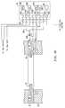
- Fig. 1Aillustrates one embodiment of a high density plasma chemical vapor deposition (HDP-CVD) system 10, in which a dielectric layer according to the present invention can be deposited.
- System 10includes a chamber 13, a vacuum system 70, a source plasma system 80A, a bias plasma system 80B, a gas delivery system 33, and a remote plasma cleaning system 50.
- the upper portion of chamber 13includes a dome 14, which is made of a dielectric material, such as alumina or aluminum nitride. Dome 14 defines an upper boundary of a plasma processing region 16. Plasma processing region 16 is bounded on the bottom by the upper surface of substrate 17 and the substrate support member 18.
- a heater plate 23 and a cold plate 24surmount, and are thermally coupled to, dome 14.
- Heater plate 23 and cold plate 24allow control of the dome temperature to within about ⁇ 10°C over a range of about 100°C to 200°C. This allows optimizing the dome temperature for the various processes. For example, it may be desirable to maintain the dome at a higher temperature for cleaning or etching processes than for deposition processes. Accurate control of the dome temperature also reduces the flake or particle counts in the chamber and improves adhesion between the deposited layer and the substrate.
- the lower portion of chamber 13includes a body member 22, which joins the chamber to the vacuum system.
- a base portion 21 of substrate support member 18is mounted on, and forms a continuous inner surface with, body member 22.
- Substratesare transferred into and out of chamber 13 by a robot blade (not shown) through an insertion/removal opening (not shown) in the side of chamber 13.
- a motorraises and lowers a lift-pin plate (not shown) that raises and lowers lift pins (not shown) that raise and lower the wafer.
- substratesUpon transfer into chamber 13, substrates are loaded onto the raised lift pins, and then lowered to a substrate receiving portion 19 of substrate support member 18.
- Substrate receiving portion 19includes an electrostatic chuck 20 that secures the substrate to substrate support member 18 during substrate processing.
- Vacuum system 70includes throttle body 25, which houses twin-blade throttle valve 26 and is attached to gate valve 27 and turbomolecular pump 28. It should be noted that throttle body 25 offers minimum obstruction to gas flow, and allows symmetric pumping. Gate valve 27 can isolate pump 28 from throttle body 25, and can also control chamber pressure by restricting the exhaust flow capacity when throttle valve 26 is fully open. The arrangement of the throttle valves, gate valve, and turbomolecular pump allow accurate and stable control of chamber pressures from between about 1 to 100 millitorr.
- the source plasma system 80Aincludes a top coil 29 and side coil 30, mounted on dome 14.
- a symmetrical ground shield(not shown) reduces electrical coupling between the coils.
- Top coil 29is powered by top source RF generator 31A
- side coil 30is powered by side source RF generator 31B, allowing independent power levels and frequencies of operation for each coil. This dual coil system allows control of the radial ion density in chamber 13, thereby improving plasma uniformity.
- Side coil 30 and top coil 29are typically inductively driven, which does not require a complimentary electrode.
- the top source RF generator 31Aprovides up to 2,500 watts of RF power at nominally 2 MHz and the side source RF generator 31B provides up to 5,000 watts of RF power at nominally 2 MHz.
- the operating frequencies of the top and side RF generatorsmay be offset from the nominal operating frequency (e.g. to 1.7-1.9 MHz and 1.9-2.1 MHz, respectively) to improve plasma-generation efficiency.
- a bias plasma system 80Bincludes a bias RF generator 31C and a bias matching network 32C.
- the bias plasma system 80Bcapacitively couples substrate portion 19 to body member 22, which act as complimentary electrodes.
- the bias plasma system 80Bserves to enhance the transport of plasma species created by the source plasma system 80A to the surface of the substrate.
- bias RF generatorprovides up to 5,000 watts of RF power at 13.56 MHz.
- a direct current (DC) fieldmay be created within process zone 16.
- DCdirect current
- providing a negative DC potential to substrate receiving portion 19 relative to body member 22may promote the transport of positively charged ions to the surface of substrate 17.
- RF generators 31A and 31Binclude digitally-controlled synthesizers and operate over a frequency range between about 1.7 to about 2.1 MHz. Each generator includes an RF control circuit (not shown) that measures reflected power from the chamber and coil back to the generator, and adjusts the frequency of operation to obtain the lowest reflected power, as understood by a person of ordinary skill in the art.
- RF generatorsare typically designed to operate into a load with a characteristic impedance of 50 ohms. RF power may be reflected from loads that have a different characteristic impedance than the generator. This can reduce power transferred to the load. Additionally, power reflected from the load back to the generator may overload and damage the generator.
- the impedance of a plasmamay range from less than 5 ohms to over 900 ohms, depending on the plasma ion density, among other factors, and because reflected power may be a function of frequency, adjusting the generator frequency according to the reflected power increases the power transferred from the RF generator to the plasma and protects the generator. Another way to reduce reflected power and improve efficiency is with a matching network.
- Matching networks 32A and 32Bmatch the output impedance of generators 31A and 31B with their respective coils 29 and 30.
- the RF control circuitmay tune both matching networks by changing the value of capacitors within the matching networks to match the generator to the load as the load changes.
- the RF control circuitmay tune a matching network when the power reflected from the load back to the generator exceeds a certain limit.
- One way to provide a constant match, and effectively disable the RF control circuit from tuning the matching networkis to set the reflected power limit above any expected value of reflected power. This may help stabilize a plasma under some conditions by holding the matching network constant at its most recent condition.
- the RF control circuitcan be used to determine the power delivered to the load (plasma) and may increase or decrease the generator output power to keep the delivered power substantially constant during deposition of a layer.
- a gas delivery system 33provides gases from several sources to the chamber for processing the substrate via gas delivery lines 38 (only some of which are shown). Gases are introduced into chamber 13 through a gas ring 37, a top nozzle 45, and a top vent 46.
- Fig. 1Bis a simplified, partial cross-sectional view of chamber 13 showing additional details of gas ring 37.
- first and second gas sources, 34A and 34B, and first and second gas flow controllers, 35A' and 35B'provide gas to ring plenum 36 in gas ring 37 via gas delivery lines 38 (only some of which are shown).
- Gas ring 37has a plurality of gas nozzles 39 and 40 (only two of which are shown) that provide a uniform flow of gas over the substrate. Nozzle length and nozzle angle may be changed by changing the gas ring 37. This allows tailoring the uniformity profile and gas utilization efficiency for a particular process within an individual chamber.
- the gas ring 37has a total of twenty-four gas nozzles, twelve first gas nozzles 40 and twelve second gas nozzles 39.
- Gas ring 37has a plurality of first gas nozzles 40 (only one of which is shown), which in a preferred embodiment are coplanar with, and shorter than, a plurality of second gas nozzles 39.
- first gas nozzles 40receive one or more gases from body plenum 41
- second gas nozzles 39receive one or more gases from gas ring plenum 36.
- process gasesmay be mixed prior to injecting the gases into chamber 13 by providing apertures (not shown) between body plenum 41 and gas ring plenum 36.
- third and fourth gas sources, 34C and 34D, and third and fourth gas flow controllers, 35C and 35D 'provide gas to body plenum via gas delivery lines 38. Additional valves, such as 43B (other valves not shown), may shut off gas from the flow controllers to the chamber.
- flammable, toxic, or corrosive gasessuch as silane or silicon tetraflouride (SiF 4 ).
- a 3-way valvesuch as valve 43B, to isolate chamber 13 from delivery line 38A and to vent delivery line 38A to vacuum foreline 44, for example.
- other similar valvessuch as 43A and 43C, may be incorporated on other gas delivery lines, such as 35A and 35C.
- Such 3-way valvesmay be placed as close to chamber 13 as practical, to minimize the volume of the unvented gas delivery line (between the 3-way valve and the chamber).
- two-way (on-off) valvesmay be placed between an MFC and the chamber or between a gas source and an MFC.
- chamber 13also has top nozzle 45 and top vent 46.
- Top nozzle 45 and top vent 46allow independent control of top and side flows of the gases, which improves film uniformity and allows fine adjustment of the film's deposition and doping parameters.
- Top vent 46is an annular opening around top nozzle 45 through which gas may flow into the chamber from the gas delivery system.
- first gas source 34Ais a silane source that supplies source gas nozzles 39 and top nozzle 45.
- Source nozzle mass flow controller (MFC) 35A'controls the amount of silane delivered to second gas nozzles 39 and top nozzle MFC 35A controls the amount of silane delivered to top gas nozzle 45.
- MFCSource nozzle mass flow controller
- two MFCs 35B and 35B'may be used to control the flow of oxygen to both top vent 46 and first gas nozzles 40 from a single source of oxygen, such as source 34B.
- the gases supplied to top nozzle 45 and top vent 46may be kept separate prior to flowing the gases into chamber 13, or the gases may be mixed in top plenum 48 before they flow into chamber 13. Separate sources of the same gas may be used to supply various portions of the chamber.
- a remote microwave-generated plasma cleaning system 50is provided to periodically clean deposition residues from chamber components.
- the cleaning systemincludes a remote microwave generator 51 that creates a plasma from a cleaning gas source 34E, such as fluorine, silicon tetrafluoride, or equivalents, in reactor cavity 53.
- a cleaning gas source 34Esuch as fluorine, silicon tetrafluoride, or equivalents
- the reactive species resulting from this plasmaare conveyed to chamber 13 through cleaning gas feed port 54 via applicator tube 55.
- the materials used to contain the cleaning plasmae.g. cavity 53 and applicator tube 55
- the distance between reactor cavity 53 and feed port 54should be kept as short as practical, as the concentration of desirable plasma species may decline with distance from reactor cavity 53.
- the cleaning plasma in a remote cavityallows the use of an efficient microwave generator and does not subject chamber components to the temperature, radiation, or bombardment of the glow discharge that may be present in an in situ plasma. Consequently, relatively sensitive components, such as electrostatic chuck 20, do not need to be covered, with a dummy wafer or otherwise protected, as may be required with an in situ plasma cleaning process.
- the gate valve 27may be closed to isolate the turbomolecular vacuum pump 28 from the chamber.
- the forelineprovides a process vacuum generated by remote vacuum pumps, which are typically mechanical vacuum pumps. Isolating the turbomolecular pump from the chamber with the gate valve protects the turbomolecular pump from corrosive compounds or other potentially harmful effects resulting from the chamber clean or other processes.
- System controller 60controls the operation of system 10.
- controller 60includes a memory 62, such as a hard disk drive, a floppy disk drive (not shown), and a card rack (not shown).
- the card rackmay contain a single-board computer (SBC) (not shown), analog and digital input/output boards (not shown), interface boards (not shown), and stepper motor controller boards (not shown).
- SBCsingle-board computer
- the system controllerconforms to the Versa Modular European (VME) standard, which defines board, card cage, and connector dimensions and types.
- the VME standardalso defines the bus structure having a 16-bit data bus and 24-bit address bus.
- System controller 31operates under the control of a computer program stored on the hard disk drive or other computer programs, such as programs stored on a floppy disk.
- the computer programdictates, for example, the timing, mixture of gases, RF power levels and other parameters of a particular process.
- the interface between a user and the system controlleris via a monitor, such as a cathode ray tube (CRT) 65, and a light pen 66, as depicted in Fig. 2.
- CTRcathode ray tube
- a light pen 66as depicted in Fig. 2.
- Fig. 2is an illustration of a portion of an exemplary system user interface used in conjunction with the exemplary CVD processing chamber of Fig. 1A.
- System controller 60includes a processor 61 coupled to a memory 62.
- memory 62may be a hard disk drive, but of course memory 62 may be other kinds of memory, such as ROM, PROM, and others.
- System controller 60operates under the control of a computer program.
- the computer programdictates the timing, temperatures, gas flows, RF power levels and other parameters of a particular process.
- the interface between a user and the system controlleris via a CRT monitor 65 and a light pen 66, as depicted in Fig. 2.
- two monitors, 65 and 65Aare used, one mounted in the clean room wall (65) for the operators and the other behind the wall (65A) for the service technicians. Both monitors simultaneously display the same information, but only one light pen (e.g. 66) is enabled.
- the operatortouches an area of the display screen and pushes a button (not shown) on the pen. The touched area confirms being selected by the light pen by changing its color or displaying a new menu, for example.
- the computer program codecan be written in any conventional computer readable programming language such as 68000 assembly language, C, C++, or Pascal. Suitable program code is entered into a single file, or multiple files, using a conventional text editor, and stored or embodied in a computer-usable medium, such as a memory system of the computer. If the entered code text is in a high level language, the code is compiled, and the resultant compiler code is then linked with an object code of precompiled windows library routines. To execute the linked compiled object code, the system user invokes the object code, causing the computer system to load the code in memory, from which the CPU reads and executes the code to perform the tasks identified in the program.
- a computer-usable mediumsuch as a memory system of the computer.
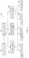
- Fig. 3shows an illustrative block diagram of the hierarchical control structure of computer program 300.
- a userenters a process set number and process chamber number into a process selector subroutine 310 in response to menus or screens displayed on the CRT monitor by using the light pen interface.
- the process setsare predetermined sets of process parameters necessary to carry out specified processes, and are identified by predefined set numbers.
- Process selector subroutine 310identifies (i) the desired process chamber in a multichamber system, and (ii) the desired set of process parameters needed to operate the process chamber for performing the desired process.
- the process parameters for performing a specific processrelate to process conditions such as, for example, process gas composition and flow rates, temperature, pressure, plasma conditions such as RF power levels, and chamber dome temperature, and are provided to the user in the form of a recipe.
- process conditionssuch as, for example, process gas composition and flow rates, temperature, pressure, plasma conditions such as RF power levels, and chamber dome temperature.
- the parameters specified by the recipeare entered utilizing the light pen/CRT monitor interface.
- the signals for monitoring the processare provided by the analog input and digital input boards of system controller and the signals for controlling the process are output on the analog output and digital output boards of system controller 60.
- a process sequencer subroutine 320comprises program code for accepting the identified process chamber and set of process parameters from the process selector subroutine 310, and for controlling operation of the various process chambers. Multiple users can enter process set numbers and process chamber numbers, or a user can enter multiple process set numbers and process chamber numbers, so sequencer subroutine 320 operates to schedule the selected processes in the desired sequence.
- sequencer subroutine 320includes a program code to perform the steps of (i) monitoring the operation of the process chambers to determine if the chambers are being used, (ii) determining what processes are being carried out in the chambers being used, and (iii) executing the desired process based on availability of a process chamber and type of process to be carried out.
- sequencer subroutine 320can be designed to take into consideration the present condition of the process chamber being used in comparison with the desired process conditions for a selected process, or the "age" of each particular user entered request, or any other relevant factor a system programmer desires to include for determining scheduling priorities.
- sequencer subroutine 320determines which process chamber and process set combination is going to be executed next, sequencer subroutine 320 causes execution of the process set by passing the particular process set parameters to a chamber manager subroutine 330A-C, which controls multiple processing tasks in chamber 13 and possibly other chambers (not shown) according to the process set determined by sequencer subroutine 320.
- chamber component subroutinesare substrate positioning subroutine 340, process gas control subroutine 350, pressure control subroutine 360, and plasma control subroutine 370.
- chamber manager subroutine 330Aselectively schedules or calls the process component subroutines in accordance with the particular process set being executed. Scheduling by chamber manager subroutine 330A is performed in a manner similar to that used by sequencer subroutine 320 in scheduling which process chamber and process set to execute.
- chamber manager subroutine 330Aincludes steps of monitoring the various chamber components, determining which components need to be operated based on the process parameters for the process set to be executed, and causing execution of a chamber component subroutine responsive to the monitoring and determining steps.
- Substrate positioning subroutine 340comprises program code for controlling chamber components that are used to load a substrate onto substrate support number 18. Substrate positioning subroutine 340 may also control transfer of a substrate into chamber 13 from, e.g., a PECVD reactor or other reactor in the multichamber system, after other processing has been completed.
- Process gas control subroutine 350has a program code for controlling process gas composition and flow rates. Subroutine 350 controls the open/close position of the safety shut-off valves, and also ramps up/down the mass flow controllers to obtain the desired gas flow rates. All chamber component subroutines, including process gas control subroutine 350, are invoked by chamber manager subroutine 330A. Subroutine 350 receives process parameters from chamber manager subroutine 330A related to the desired gas flow rates.
- process gas control subroutine 350operates by opening the gas supply lines, and repeatedly (i) reading the necessary mass flow controllers, (ii) comparing the readings to the desired flow rates received from chamber manager subroutine 330A, and (iii) adjusting the flow rates of the gas supply lines as necessary. Furthermore, process gas control subroutine 350 may include steps for monitoring the gas flow rates for unsafe rates, and activating the safety shut-off valves when an unsafe condition is detected.
- an inert gassuch as argon
- the process gas control subroutine 350is programmed to include steps for flowing the inert gas into chamber 13 for an amount of time necessary to stabilize the pressure in the chamber. The above-described steps may then be carried out.
- the process gas control subroutine 350may include steps for bubbling a delivery gas such as helium through the liquid precursor in a bubbler assembly or for introducing the helium to a liquid injection valve.
- a delivery gassuch as helium
- the process gas control subroutine 350regulates the flow of the delivery gas, the pressure in the bubbler, and the bubbler temperature to obtain the desired process gas flow rates.
- the desired process gas flow ratesare transferred to process gas control subroutine 350 as process parameters.
- the process gas control subroutine 350includes steps for obtaining the necessary delivery gas flow rate, bubbler pressure, and bubbler temperature for the desired process gas flow rate by accessing a stored table containing the necessary values for a given process gas flow rate. Once the necessary values are obtained, the delivery gas flow rate, bubbler pressure and bubbler temperature are monitored, compared to the necessary values and adjusted accordingly.
- the process gas control subroutine 350may also control the flow of heat-transfer gas, such as helium (He), through the inner and outer passages in the wafer chuck with an independent helium control (IHC) subroutine (not shown).
- the gas flowthermally couples the substrate to the chuck.
- the waferis heated by the plasma and the chemical reactions that form the layer, and the He cools the substrate through the chuck, which may be water-cooled. This keeps the substrate below a temperature that may damage preexisting features on the substrate.
- Pressure control subroutine 360includes program code for controlling the pressure in chamber 13 by regulating the size of the opening of throttle valve in the exhaust portion of the chamber.
- the first methodrelies on characterizing the chamber pressure as it relates to, among other things, the total process gas flow, size of the process chamber, and pumping capacity.
- the first methodsets throttle valve 26 to a fixed position. Setting throttle valve 26 to a fixed position may eventually result in a steady-state pressure.
- the chamber pressuremay be measured, with a manometer for example, and throttle valve 26 position may be adjusted according to pressure control subroutine 360, assuming the control point is within the boundaries set by gas flows and exhaust capacity.
- the former methodmay result in quicker chamber pressure changes, as the measurements, comparisons, and calculations associated with the latter method are not invoked.
- the former methodmay be desirable where precise control of the chamber pressure is not required, whereas the latter method may be desirable where an accurate, repeatable, and stable pressure is desired, such as during the deposition of a layer.
- pressure control subroutine 360When pressure control subroutine 360 is invoked, the desired (or target) pressure level is received as a parameter from chamber manager subroutine 330A. Pressure control subroutine 360 operates to measure the pressure in chamber 13 by reading one or more conventional pressure manometers connected to the chamber, compare the measure value(s) to the target pressure, obtain proportional, integral, and differential (PID) values from a stored pressure table corresponding to the target pressure, and adjust throttle valve 26 according to the PID values obtained from the pressure table. Alternatively, pressure control subroutine 360 may open or close throttle valve 26 to a particular opening size to regulate the pressure in chamber 13 to a desired pressure or pressure range.
- PIDproportional, integral, and differential
- Plasma control subroutine 370comprises program code for controlling the frequency and power output setting of RF generators 31A and 31B, and for tuning matching networks 32A and 32B.
- Plasma control subroutine 370like the previously described chamber component subroutines, is invoked by chamber manager subroutine 330A.
- An example of a system which may incorporate some or all of the subsystems and routines described abovewould be an Ultima System, manufactured by Applied Materials, configured to practice the present invention.
- Fig. 4illustrates a simplified cross-sectional view of an integrated circuit 500 incorporating features of the present invention.
- Integrated circuit 500may be fabricated on a semiconductor wafer, such as a silicon wafer, gallium-arsenide wafer, or other wafer.
- integrated circuit 500includes NMOS and PMOS transistors 503 and 506, which are separated and electrically isolated from each other by a field oxide region 507.
- Each transistor 503 and 506comprises a source region 508, a gate region 509, and a drain region 510.
- a premetal dielectric layer 511separates transistors 503 and 506 from metal layer M1, with connections between metal layer M1 and the transistors made by contacts 512.
- Metal layer M1is one of four metal layers, M1-M4, included in integrated circuit 500. Each metal layer M1-M4 is separated from adjacent metal layers by respective intermetal dielectric (IMD) layers 513A-C. Adjacent metal layers are connected at selected openings by vias 514. Planar passivation layer 515 overlies metal layer M4.
- IMDintermetal dielectric
- Embodiments of the present inventionare particularly useful for IMD layers, but may find uses in each of the dielectric layers shown in integrated circuit 500. It should be understood that the simplified integrated circuit 500 is for illustrative purposes only. One of ordinary skill in the art could implement the present method for fabrication of other integrated circuits, such as microprocessors, application-specific integrated circuits, memory devices, and the like. Additionally, the method of the present invention may be used in the fabrication of integrated circuits using other technologies, such as BiCMOS, NMOS, bipolar, and others.
- an insulating film 602 formed according to an embodiment of the present inventionis shown deposited over metal lines 601 and within gap 607 on wafer 606.
- wafer 606is a silicon wafer.
- Insulating film 602is comprised of USG liner 603, FSG bulk layer 604, and FSG skin layer 605.
- USG liner 603, FSG bulk layer 604, and FSG skin layer 605are formed in one substantially continuous deposition process.
- USG liner 603is between about 150 A and 600 A, but more preferably between about 300 A and 400 A.
- Proper sequencing of the recipe steps prior to and during the formation of the USG layer 603, FSG bulk layer 604, and FSG skin layer 605insure superior stability of insulating film 602.
- antireflective layer 619sits atop metal lines 601.
- antireflective layer 619may be a layer of titanium nitride.
- the proper sequencing of recipe stepsrelates to an HDP-CVD deposition system, in which the substrate is heated to the proper temperature by a plasma before depositing any USG.
- the substratemay be heated by electrical resistance heaters, radiant lamp heaters, heat of reaction, or other means, in addition to the RF plasma.
- the surface of the substrateis kept reasonably hot as fluorine is admitted into the chamber.
- the plasmaenhances deposition characteristics, but may also sputter off some or all of the deposited layer. This process is called cosputtering.
- the proper RF power levelis selected according to the process pressure, substrate temperature, types of deposition gases used, and pre-existing patterned layers on the wafer, among other things.
- the fluorine speciesmay co-etch the FSG layer as it is being deposited. This may be described as a ratio of the rate of deposition to the rate of etching. Ratios greater than 1 result in a net deposition, and ratios less than 1 indicate that material is being etched faster than it is being deposited.
- the substrate temperaturemay be controlled with a thermostat, or the substrate temperature may be characterized for specific operating conditions.
- the substrateis heated with the plasma according to characterizations of operating conditions of the deposition system.
- WERRwet etch relative ratio
- Fig. 6is a flow chart showing one embodiment of the sequence of steps of the present invention.
- the temperature of the substrate when fluorine is first admitted into the chamberis important because it affects how well fluorine is incorporated into the growth surface of the glass layer. Accordingly, the sequence of steps involved with preheating the substrate prior to the onset of a halogen-containing gas flow may be critical. If the substrate has pre-existing aluminum features, it may be especially important to heat the substrate sufficiently to form an initial layer of FSG at a sufficiently high temperature without damaging the aluminum features.
- the following processrelates to a nominally 200 mm diameter silicon wafer in a deposition chamber with a specific interior volume; however, those skilled in the art will appreciate that the process could be modified for different substrate materials, different substrate sizes, and different chamber volumes, among other variations.
- a substrateis placed in the deposition system (step 701), and argon is admitted at a rate of 95 sccm to gas nozzles 39 and at a rate of 15 sccm to top nozzle 45.
- These gas flowsestablish an initial chamber pressure of about 50 millitorr (step 702), based on a fixed throttle valve setting.
- a plasmais struck at this initial pressure (step 703) by applying 1,000 W of RF power to top coil 29.
- One secondis allowed to establish a stable plasma, before the throttle valve is opened to lower the chamber pressure to the deposition pressure of between 3-5 millitorr.
- the throttle valvemay be opened to a set position for a specific period of time, which may result in a desired pressure, based upon prior characterization of the deposition system. Concurrent with setting the chamber pressure to the deposition pressure, the total plasma energy is increased by applying 2,000 W of RF power to the side coil, in addition to the 1,000 W already being applied to the top coil (step 704).
- the top coil poweris increased to 1500 W
- the side coil poweris increased to 3500 W
- the oxygen flow to the chamberis turned on (step 705) at an initial flow of 30 sccm.
- a negative voltageis applied to an e-chuck (step 706), which draws the substrate in intimate contact with the e-chuck. Applying a negative, rather than positive, voltage enhances the transport of positively charged plasma species to the substrate.
- the e-chuckhas inner and outer cooling rings intended to carry heat-transfer gas. Helium is a preferred gas for flowing through the inner and outer channels to thermally couple the substrate and the e-chuck.
- the e-chuckmay be cooled (or in some embodiments heated) by heat-transfer liquid, such as water or a water/glycol mixture, flowing in passages (not shown) within the e-chuck.
- the heat-transfer liquidis maintained at a temperature of about 60°C by the cooling system. Because helium does not yet flow through the cooling rings, there is relatively little thermal transfer between the substrate and the e-chuck. This allows the substrate to heat up more rapidly than if the cooling helium was flowing.
- the substrateis preheated by the plasma for six seconds (step 706).
- the oxygen flowis increased to 126 sccm, flowing from the oxidizer nozzles at a rate of 110 sccm, and flowing from the top vent at a rate of 16 sccm.
- the thermal mass of the system components and the short time period involvedmake the use of feedback-based temperature control systems difficult for this step of the process. Therefore, it is important to understand the relationship between the plasma heating, the thermal mass of the substrate and chuck, and the power and pressure of the plasma. For example, a plasma at a higher pressure may transfer more heat to the substrate and damage pre-existing features on the substrate, such as aluminum traces, if maintained for the same period under otherwise similar conditions.
- silaneis admitted to the chamber at a rate of 35 sccm (step 707), which includes 30 sccm from source gas nozzles 39 and 5 sccm from top nozzle 45. This grows a layer of USG about 300-400 A thick in a period of 3 seconds on the preheated substrate, in preparation for FSG deposition.
- heliumis flowed through the cooling channels in e-chuck 20 (step 708), thermally coupling the substrate to the water-cooled chuck and thus cooling the substrate.
- the helium pressure within these channelsmay be higher than the chamber pressure, resulting in a force pushing the substrate away from the chuck, however, the attractive force of the e-chuck to the substrate is sufficient to hold the wafer on the e-chuck.
- the next stepintroduces fluorine into the deposition system (step 709).
- Silicon tetrafluorideis admitted at the relatively low flow rate of 5 sccm from oxidizer nozzles 40 for one second. Among other things, this fills the distribution lines down stream from the SiF 4 mass flow controller with SiF 4 . It is believed that the initial fluorine species present at the onset of the SiF 4 flow react on a substrate surface that is above at least 100°C, as a result of the preceding preheat step 706. This may result in an initial FSG layer 610 (Fig. 5) in which the fluorine is tightly bound in the glass lattice.
- this initial FSG layerdepends on many factors, including the thermal capacity of the plasma-heated wafer, and may be only a few atomic layers, or about 100 A, thick. Free fluorine (fluorine that is not tightly bound in the glass) is undesirable because free fluorine may corrode metal traces or antireflective layers, especially titanium nitride antireflective layers. The relatively low concentration of fluorine present at the onset of the SiF 4 flow limits the potential accumulation of free fluorine in this portion of the layer.
- the pressure feedback loop controlling the throttle valveis activated. That is, in the preceding steps, the throttle valve was set to a fixed position, the chosen position being appropriate for the chamber volume, exhaust capacity, and gas flows, as discussed above. Now, the throttle valve position is controlled according to a pressure reading from a manometer to maintain a chamber pressure of 6 millitorr. This provides greater accuracy, stability, and repeatability of chamber pressure during the deposition process.
- the RF bias poweris now reduced (step 710), in anticipation of the main deposition step.
- the RF bias power levelis set to 900 W to top coil 29 and 2300 W delivered to side coil 30.
- the SiF 4 flowis increased to 10 sccm, and the silane flow is increased to 45 sccm and 4.5 sccm from source nozzles 39 and top nozzle 45, respectively.
- the oxygen flowis decreased to 84 sccm and 5.7 sccm from oxidizer nozzles 40 and top vent 46, respectively. These conditions are held for 2 seconds to set and maintain the proper pressure for the desired FSG deposition to fill narrow gaps without overetching the existing substrate features by either sputter etching or fluorine etching.
- a relatively high quality FSG layer(one that tightly binds fluorine into the glass structure) about 200 A thick is formed over the liner because the surface of the liner layer is still relatively hot, as discussed above.
- the relatively high substrate surface temperature, low rate of deposition gas flows, and low RF bias powerare believed to all contribute to the quality of the initial FSG layer.
- step 711The majority of the FSG layer is deposited during the main deposition step (step 711).
- the temperature of the waferis lower in this step than in the preceding step, increasing the deposition-to-etch ratio, which results in a higher rate of deposition.
- the RF bias power matching control circuitis essentially disabled by increasing the control limit to 1500 W. This means that the RF bias power match system will not attempt to alter the configuration of the matching networks unless the reflected power exceeds 2500 W. Because the matching networks have already been tuned to the chamber with a plasma during the preceding steps, it is unlikely that the reflected power will exceed 2500 W during this deposition step.
- step 711900 W of power is supplied to top coil 29, and 2300 Watts of power is supplied to side coil 30.
- Throttle valve 26is controlled to maintain a chamber pressure of 6 millitorr, while the argon flow to source nozzles 39 is decreased to 46 sccm and the argon flow through top nozzle 45 is decreased to 9 sccm. The deposition proceeds for approximately 157 seconds, depending on the desired final thickness.
- the flow of silane and SiF 4are turned off (step 712) and the gas delivery lines associated with these flows are dumped to foreline vacuum 44 through three-way valves, such as valves 43A-C, as shown in Fig. 1A.
- Thisremoves gas residue from these delivery lines. It is undesirable to leave some gases in their respective delivery lines, as some gases may be flammable, toxic, or corrosive. Additionally, some reactant gases are unstable, and allowing them to remain in the line until the next wafer deposition may result in inconsistent or contaminated layers.
- the RF bias power match control limitsare also reduced to 500 W during this step.
- the helium flowing in the cooling channels in e-chuck 20is turned off, and the power to top RF coil 29 is increased to 1000 W, while the power to side RF coil 30 is decreased to 2000 W (step 713).
- Thismay heat the surface of the FSG layer, forming a thin skin of FSG in which fluorine is more tightly bound in the glass structure than in the bulk FSG layer.
- This skin layerreduces the transport of water or water vapor to or from the bulk FSG layer.
- Silicon oxide, and especially fluorinated silicon oxide (which forms the FSG layer)is hydrophilic, that is, it will absorb water vapor from the surrounding environment. Some water vapor is present in the deposition environment.
- This water vapormay be incorporated into the bulk FSG layer because, among other reasons, the wafer is below 100°C. Additionally, were it not for the skin layer, the bulk FSG might absorb water from the air, forming haze or bubbles, or which may combine with free or loosely bound fluorine to form corrosive hydrofluoric acid, or which may increase the relative dielectric constant of the layer.
- the timing of the next stepis important in some embodiments.
- the helium in the cooling channels(which is not flowing but still provides some pressure to the backside of the wafer) is vented to the foreline vacuum (step 714) and about 3 seconds later, the e-chuck is turned off by grounding the chuck (step 715).
- the plasmaprovides a source of ions to neutralize the electrostatic forces between the substrate and the e-chuck, and the residual helium back pressure gently breaks the seal between the substrate and chuck before all of the helium is evacuated by the foreline. Without the helium back pressure, the substrate may stick to the chuck, making unloading difficult. If the e-chuck is turned off before enough helium has vented, the substrate may flip off the chuck.
- the e-chuckis turned off without a plasma present, it may take an unacceptably long time for the wafer and chuck to equilibrate, and allow removal of the substrate from the chuck.
- the waferis then ready for dechucking (step 716) and removal from the chamber (step 717).
- the exemplary process described aboveis for illustrative purposes only. Many process parameters relate to the specific chamber the process is intended to be performed in, in this instance a commercially available ULTIMA chamber, manufactured by Applied Materials, Inc., of Santa Clara, California. Other chambers may have different volumes, exhaust capacities, plasma configurations, wafer chucking systems, etc., which may result in a process with different pressures, gas flow rates, plasma powers, times, or other process parameters. Additionally, different substrates may result in different process parameters. For example, a process intended for a substrate with a different thermal capacity or thermal conductivity may have longer or shorter preheating step. Additionally, a substrate with pre-existing features that can withstand a higher temperature than aluminum features may be heated to a higher temperature without damage. Furthermore, other gases may be used in the process, such as TEOS for a source of silicon, or F 2 as a source of fluorine.
- Sampleswere prepared by growing layers on 200-mm silicon wafers according to the exemplary process given above. Some samples had metal traces 0.8 ⁇ m high that were spaced 0.18 ⁇ m apart (the gap having an aspect ratio of 4.44:1). These gaps were filled with the deposited layer (USG liner layer, FSG bulk layer, and FSG skin layer), sectioned, and examined using a scanning electron microscope. No voids resulting from the gaps growing shut were found. The layers incorporated sufficient fluorine to lower the relative dielectric constant of the layer to 3.73.
- FSG layersStability of the FSG layers was confirmed by storing a sample of 5 wafers for 21 days and inspecting for haze or bubble formation, and nondestructively testing film parameters such as residual film stress and dielectric constant. No haze or bubbles were observed in the sample population, and no significant change in film stress or dielectric constant occurred.
- pyrometric measurementswhich is a destructive test method, were done on another population of wafers with about 6000-A-thick deposited layers. Wafers were stored under ambient conditions for 1, 2, and 3 weeks. The sample wafers were heated to progressively higher temperatures in a vacuum while measuring the concentration of water vapor released from the sample. Integrating the area under the curve provides an indication of the total water desorbed from the wafer. No significant outgassing or desorbtion of water vapor was observed at temperatures up to 500°C.
- Fig. 7shows a pyrogram for a wafer as deposited (trace 801) and for the same wafer after removing approximately 1700 A from the surface of the FSG layer with a wet etch process (trace 802). It is assumed that this etch removed the FSG skin layer. These traces show that the FSG skin layer provides a barrier to the adsorption and desorbtion of water from the bulk FSG layer, thus promoting layer stability.
Landscapes
- Chemical & Material Sciences (AREA)
- Engineering & Computer Science (AREA)
- Organic Chemistry (AREA)
- General Chemical & Material Sciences (AREA)
- Chemical Kinetics & Catalysis (AREA)
- Materials Engineering (AREA)
- General Physics & Mathematics (AREA)
- Microelectronics & Electronic Packaging (AREA)
- Physics & Mathematics (AREA)
- Condensed Matter Physics & Semiconductors (AREA)
- Mechanical Engineering (AREA)
- Manufacturing & Machinery (AREA)
- Computer Hardware Design (AREA)
- Metallurgy (AREA)
- Power Engineering (AREA)
- Inorganic Chemistry (AREA)
- Life Sciences & Earth Sciences (AREA)
- Geochemistry & Mineralogy (AREA)
- Chemical Vapour Deposition (AREA)
- Formation Of Insulating Films (AREA)
- Manufacture, Treatment Of Glass Fibers (AREA)
- Element Separation (AREA)
Abstract
Description
Claims (14)
- A method for forming a film on a substrate in a depositionsystem chamber, the method comprising the steps of:(a flowing a silicon-containing process gas into the chamberunder conditions suitable for depositing silicon glass;(b forming a relatively thin layer of undoped silicon glass onthe substrate;(c) flowing a halogen-containing gas, preferably silane(SiF4.), into the chamber at a flow rate to form a first portion of a halogen-containingsilicon oxide layer on said layer of undoped silicon glass; and(d) increasing the flow rate of the halogen-containing gas toform a second portion of the halogen-containing silicon oxide layer.
- The method of claim 1, wherein the substrate in the chamber isheated in step (a) to a temperature of at least about 100°C, and wherein thethe temperature of the substrate is lowered in step (d).
- The method of claim 2, wherein said substrate is heated with aplasma.
- The method of claim 1, wherein the temperature of thesubstrate is at least about 100°C in step (c).
- The method of claim 1, wherein said layer of undoped siliconglass is between about 300 Å and about 400 Å thick.
- The method of claim 1, wherein said first portion of saidhalogen-containing silicon glass layer is less than about 300 Å thick.
- The method of claim 6, wherein said first portion of saidhalogen-containing silicon glass layer includes a lower-halogen layer lessthan about 100 Å thick formed at an onset of said flow of said halogen-containinggas and a higher-halogen layer formed on said lower-halogen layerduring a main flow of said flow of said halogen-containing gas.
- The method of claim 1, wherein said step (d) occurs less thanabout 5 seconds after said step (c).
- The method of claim 1, further comprising the step of coolingsaid substrate by flowing a coolant medium, preferably helium, adjacent to abackside of said substrate after said forming of said layer of undoped siliconglass in step (b).
- The method of claim 1 wherein said layer of undoped siliconglass is between about 150 Å and about 600 Å thick.
- The method of claim 1, further comprising the steps of (e)reducing said RF power level, thereby reducing said heating of saidsubstrate; and (f) forming a third portion of the film.
- The method of claim 1, further comprising, after step (e), thestep of increasing a rate of flow of said halogen-containing gas.
- The method of claim 1, comprising the steps of:heating the substrate to a temperature between about 100°C and450°C with a plasma at a first RF power level prior to flowing a source gasinto the chamber;flowing a non-halogen containing source gas into the chamber to form a layer of undoped silicon glass on the substrate;flowing a coolant medium adjacent to a backside of the substrate;flowing a halogen-containing gas into the chamber to form a firstportion of a layer of halogen-doped silicon glass on the layer of said undopedsilicon glass while said substrate is at a second temperature above about 100°C;reducing said first RF power level; andforming a second portion of the layer of halogen-doped silicon glass.
- A substrate-processing apparatus for forming a fluorinatedsilicon glass layer on a substrate, the apparatus comprising:(a) a processing chamber;(b) a gas delivery system configured to deliver a non-halogen-containingsource gas to said processing chamber and a halogen-containingsource gas to said processing chamber;(c) an RF plasma system configured to form a plasma within saidprocessing chamber;(d) a vacuum system configured to set and maintain a selectedpressure within said processing chamber;(e) a controller configured to control said gas delivery system, saidplasma system, and said vacuum system; and(f) a memory, coupled to said controller, comprising a computer-readablemedium having a computer-readable program embodied therein fordirecting operation of the substrate processing apparatus, said computer-readableprogram being scharacterized by:(i) a first set of computer instructions for controlling said gas deliverysystem and said plasma system to flow a plasma gas into said chamber and toform a plasma at a plasma power therefrom;(ii) a second set of computer instructions for controlling said gasdelivery system to flow a non-halogen-containing source gas into said chamber after said plasma has heated a substrate in said chamber for a firstperiod of time to a temperature of at least about 100 °C to form a non-halogenatedlayer;(iii) a third set of computer instructions for flowing a coolant mediumadjacent to a backside of the substrate;(iv) a fourth set of computer instructions for controlling said gasdelivery system to flow a halogen-containing gas at a halogen-containing gasflow rate into said chamber within a second period of time, wherein saidsecond period of time is sufficient to form a first portion of a halogen-containinglayer on said non-halogenated layer before the temperature of thesubstrate falls below about 100 °C; and(v) a fifth set of computer instructions for controlling said gas deliverysystem and said plasma system to reduce said plasma power and to increasesaid halogen-containing gas flow rate.
Applications Claiming Priority (2)
| Application Number | Priority Date | Filing Date | Title |
|---|---|---|---|
| US868286 | 1992-04-13 | ||
| US08/868,286US5937323A (en) | 1997-06-03 | 1997-06-03 | Sequencing of the recipe steps for the optimal low-k HDP-CVD processing |
Publications (3)
| Publication Number | Publication Date |
|---|---|
| EP0883166A2true EP0883166A2 (en) | 1998-12-09 |
| EP0883166A3 EP0883166A3 (en) | 1998-12-30 |
| EP0883166B1 EP0883166B1 (en) | 2006-08-09 |
Family
ID=25351375
Family Applications (1)
| Application Number | Title | Priority Date | Filing Date |
|---|---|---|---|
| EP98107996AExpired - LifetimeEP0883166B1 (en) | 1997-06-03 | 1998-04-30 | Deposition of fluorinated silicon glass |
Country Status (6)
| Country | Link |
|---|---|
| US (2) | US5937323A (en) |
| EP (1) | EP0883166B1 (en) |
| JP (1) | JP4237845B2 (en) |
| KR (1) | KR100562206B1 (en) |
| DE (1) | DE69835479T2 (en) |
| TW (1) | TW406358B (en) |
Cited By (16)
| Publication number | Priority date | Publication date | Assignee | Title |
|---|---|---|---|---|
| WO1999057747A1 (en)* | 1998-05-01 | 1999-11-11 | Applied Materials, Inc. | Cvd apparatus and process for depositing titanium films |
| EP1073108A1 (en)* | 1999-07-27 | 2001-01-31 | Applied Materials, Inc. | Chemical vapor deposition process for dielectric material |
| EP1081249A1 (en)* | 1999-09-01 | 2001-03-07 | Applied Materials, Inc. | Method for depositing fluorinated silica glass layers |
| GB2356289A (en)* | 1999-08-19 | 2001-05-16 | Lucent Technologies Inc | Process for deposition of low-k dielectric gap filling layer onto high aspect ratio features in integrated circuits |
| EP1170397A2 (en)* | 2000-07-07 | 2002-01-09 | Applied Materials, Inc. | Deposition of amorphous silicon films by high density plasma CVD at low temperatures |
| US6348417B1 (en) | 1998-04-03 | 2002-02-19 | Nec Corporation | Semiconductor device manufacturing apparatus and semiconductor device manufacturing method |
| GB2367426A (en)* | 2000-04-04 | 2002-04-03 | Agere Syst Guardian Corp | Silicon rich oxides and fluorinated silicon oxide insulating layers |
| US6511922B2 (en) | 2001-03-26 | 2003-01-28 | Applied Materials, Inc. | Methods and apparatus for producing stable low k FSG film for HDP-CVD |
| US6903031B2 (en) | 2003-09-03 | 2005-06-07 | Applied Materials, Inc. | In-situ-etch-assisted HDP deposition using SiF4 and hydrogen |
| US6929700B2 (en)* | 2001-05-11 | 2005-08-16 | Applied Materials, Inc. | Hydrogen assisted undoped silicon oxide deposition process for HDP-CVD |
| US7087536B2 (en) | 2004-09-01 | 2006-08-08 | Applied Materials | Silicon oxide gapfill deposition using liquid precursors |
| US7183227B1 (en) | 2004-07-01 | 2007-02-27 | Applied Materials, Inc. | Use of enhanced turbomolecular pump for gapfill deposition using high flows of low-mass fluent gas |
| US7196021B2 (en) | 2001-05-11 | 2007-03-27 | Applied Materials, Inc. | HDP-CVD deposition process for filling high aspect ratio gaps |
| US7229931B2 (en) | 2004-06-16 | 2007-06-12 | Applied Materials, Inc. | Oxygen plasma treatment for enhanced HDP-CVD gapfill |
| US7595088B2 (en) | 2003-01-23 | 2009-09-29 | Applied Materials, Inc. | Hydrogen assisted HDP-CVD deposition process for aggressive gap-fill technology |
| US7678715B2 (en) | 2007-12-21 | 2010-03-16 | Applied Materials, Inc. | Low wet etch rate silicon nitride film |
Families Citing this family (697)
| Publication number | Priority date | Publication date | Assignee | Title |
|---|---|---|---|---|
| US6251758B1 (en)* | 1994-11-14 | 2001-06-26 | Applied Materials, Inc. | Construction of a film on a semiconductor wafer |
| US6191026B1 (en)* | 1996-01-09 | 2001-02-20 | Applied Materials, Inc. | Method for submicron gap filling on a semiconductor substrate |
| US6083852A (en)* | 1997-05-07 | 2000-07-04 | Applied Materials, Inc. | Method for applying films using reduced deposition rates |
| US6228781B1 (en) | 1997-04-02 | 2001-05-08 | Applied Materials, Inc. | Sequential in-situ heating and deposition of halogen-doped silicon oxide |
| US6136685A (en)* | 1997-06-03 | 2000-10-24 | Applied Materials, Inc. | High deposition rate recipe for low dielectric constant films |
| JPH11232338A (en)* | 1998-02-17 | 1999-08-27 | Toshiba Corp | Process flow creation device, process flow creation method, and computer-readable recording medium recording process flow creation program |
| US6194038B1 (en)* | 1998-03-20 | 2001-02-27 | Applied Materials, Inc. | Method for deposition of a conformal layer on a substrate |
| US6200911B1 (en)* | 1998-04-21 | 2001-03-13 | Applied Materials, Inc. | Method and apparatus for modifying the profile of narrow, high-aspect-ratio gaps using differential plasma power |
| US6030881A (en)* | 1998-05-05 | 2000-02-29 | Novellus Systems, Inc. | High throughput chemical vapor deposition process capable of filling high aspect ratio structures |
| US6150285A (en) | 1998-06-17 | 2000-11-21 | Advanced Micro Devices, Inc. | Method for simultaneous deposition and sputtering of TEOS |
| TW410435B (en)* | 1998-06-30 | 2000-11-01 | United Microelectronics Corp | The metal interconnection manufacture by using the chemical mechanical polishing process |
| US6265779B1 (en)* | 1998-08-11 | 2001-07-24 | International Business Machines Corporation | Method and material for integration of fuorine-containing low-k dielectrics |
| US5994778A (en)* | 1998-09-18 | 1999-11-30 | Advanced Micro Devices, Inc. | Surface treatment of low-k SiOF to prevent metal interaction |
| US6566757B1 (en) | 1998-11-30 | 2003-05-20 | Intel Corporation | Stabilization of low dielectric constant film with in situ capping layer |
| US6255233B1 (en)* | 1998-12-30 | 2001-07-03 | Intel Corporation | In-situ silicon nitride and silicon based oxide deposition with graded interface for damascene application |
| US6528865B1 (en)* | 1999-01-22 | 2003-03-04 | Intel Corporation | Thin amorphous fluorocarbon films |
| US6218284B1 (en)* | 1999-02-01 | 2001-04-17 | United Microelectronics, Corp. | Method for forming an inter-metal dielectric layer |
| US6180540B1 (en)* | 1999-02-18 | 2001-01-30 | Taiwan Semiconductor Manufacturing Company | Method for forming a stabilized fluorosilicate glass layer |
| US6261975B1 (en)* | 1999-03-04 | 2001-07-17 | Applied Materials, Inc. | Method for depositing and planarizing fluorinated BPSG films |
| JP4053173B2 (en)* | 1999-03-29 | 2008-02-27 | 東京エレクトロン株式会社 | Microwave plasma processing apparatus and method |
| US6001746A (en)* | 1999-05-20 | 1999-12-14 | United Microelectronics Corp. | Method of forming an undoped silicate glass layer on a semiconductor wafer |
| US6153543A (en)* | 1999-08-09 | 2000-11-28 | Lucent Technologies Inc. | High density plasma passivation layer and method of application |
| US6165915A (en)* | 1999-08-11 | 2000-12-26 | Taiwan Semiconductor Manufacturing Company | Forming halogen doped glass dielectric layer with enhanced stability |
| US6346476B1 (en)* | 1999-09-27 | 2002-02-12 | Taiwan Semiconductor Manufacturing Company | Method for enhancing line-to-line capacitance uniformity of plasma enhanced chemical vapor deposited (PECVD) inter-metal dielectric (IMD) layers |
| US6319814B1 (en)* | 1999-10-12 | 2001-11-20 | United Microelectronics Corp. | Method of fabricating dual damascene |
| TW429516B (en)* | 1999-10-22 | 2001-04-11 | United Microelectronics Corp | Manufacturing method for inter-metal dielectrics |
| US6572924B1 (en)* | 1999-11-18 | 2003-06-03 | Asm America, Inc. | Exhaust system for vapor deposition reactor and method of using the same |
| US6432808B1 (en)* | 1999-12-03 | 2002-08-13 | Xilinx, Inc. | Method of improved bondability when using fluorinated silicon glass |
| US6472336B1 (en)* | 2000-02-23 | 2002-10-29 | Advanced Micro Devices, Inc. | Forming an encapsulating layer after deposition of a dielectric comprised of corrosive material |
| US6432842B2 (en)* | 2000-03-30 | 2002-08-13 | Tokyo Electron Limited | Coating method and coating apparatus |
| KR20010087598A (en)* | 2000-03-08 | 2001-09-21 | 황 철 주 | HDP-CVD Apparatus and gap filling method using the same |
| US6380066B1 (en) | 2000-03-21 | 2002-04-30 | Chartered Semiconductor Manufacturing Ltd. | Methods for eliminating metal corrosion by FSG |
| US20020005539A1 (en) | 2000-04-04 | 2002-01-17 | John Whitman | Spin coating for maximum fill characteristic yielding a planarized thin film surface |
| US6506690B1 (en)* | 2000-04-25 | 2003-01-14 | Agere Systems Inc. | Method for forming dielectric stack including second dielectric layer with lower undoped portion and upper doped portion |
| US6511923B1 (en) | 2000-05-19 | 2003-01-28 | Applied Materials, Inc. | Deposition of stable dielectric films |
| US6559026B1 (en)* | 2000-05-25 | 2003-05-06 | Applied Materials, Inc | Trench fill with HDP-CVD process including coupled high power density plasma deposition |
| US6479385B1 (en) | 2000-05-31 | 2002-11-12 | Taiwan Semiconductor Manufacturing Company | Interlevel dielectric composite layer for insulation of polysilicon and metal structures |
| US6548901B1 (en) | 2000-06-15 | 2003-04-15 | International Business Machines Corporation | Cu/low-k BEOL with nonconcurrent hybrid dielectric interface |
| KR100332314B1 (en)* | 2000-06-24 | 2002-04-12 | 서성기 | Reactor for depositing thin film on wafer |
| KR100444149B1 (en)* | 2000-07-22 | 2004-08-09 | 주식회사 아이피에스 | ALD thin film depositin equipment cleaning method |
| US6376360B1 (en) | 2000-08-18 | 2002-04-23 | Chartered Semiconductor Manufacturing Ltd. | Effective retardation of fluorine radical attack on metal lines via use of silicon rich oxide spacers |
| US6335288B1 (en)* | 2000-08-24 | 2002-01-01 | Applied Materials, Inc. | Gas chemistry cycling to achieve high aspect ratio gapfill with HDP-CVD |
| US6521529B1 (en)* | 2000-10-05 | 2003-02-18 | Advanced Micro Devices, Inc. | HDP treatment for reduced nickel silicide bridging |
| US6524969B2 (en)* | 2000-10-05 | 2003-02-25 | Applied Materials, Inc. | High density plasma chemical vapor deposition (HDP-CVD) processing of gallium arsenide wafers |
| WO2002033728A1 (en)* | 2000-10-19 | 2002-04-25 | Robert Bosch Gmbh | Device and method for the etching of a substrate by means of an inductively coupled plasma |
| US6458722B1 (en)* | 2000-10-25 | 2002-10-01 | Applied Materials, Inc. | Controlled method of silicon-rich oxide deposition using HDP-CVD |
| US6335274B1 (en)* | 2000-11-17 | 2002-01-01 | Macronix International Co., Ltd. | Method for forming a high-RI oxide film to reduce fluorine diffusion in HDP FSG process |
| US6363624B1 (en) | 2000-11-21 | 2002-04-02 | Applied Materials, Inc. | Apparatus for cleaning a semiconductor process chamber |
| US6451687B1 (en) | 2000-11-24 | 2002-09-17 | Chartered Semiconductor Manufacturing Ltd. | Intermetal dielectric layer for integrated circuits |
| US6479098B1 (en)* | 2000-12-26 | 2002-11-12 | Taiwan Semiconductor Manufacturing Company | Method to solve particle performance of FSG layer by using UFU season film for FSG process |
| US6514870B2 (en) | 2001-01-26 | 2003-02-04 | Applied Materials, Inc. | In situ wafer heat for reduced backside contamination |
| US6447651B1 (en) | 2001-03-07 | 2002-09-10 | Applied Materials, Inc. | High-permeability magnetic shield for improved process uniformity in nonmagnetized plasma process chambers |
| TW531893B (en)* | 2001-03-13 | 2003-05-11 | Sanyo Electric Co | Semiconductor device and manufacture method therefor |
| US6713406B1 (en) | 2001-03-19 | 2004-03-30 | Taiwan Semiconductor Manufacturing Company | Method for depositing dielectric materials onto semiconductor substrates by HDP (high density plasma) CVD (chemical vapor deposition) processes without damage to FET active devices |
| US6576545B1 (en) | 2001-03-29 | 2003-06-10 | Advanced Micro Devices, Inc. | Semiconductor devices with dual nature capping/ARC layers on fluorine doped silica glass inter-layer dielectrics and method of forming capping/ARC layers |
| US6518646B1 (en) | 2001-03-29 | 2003-02-11 | Advanced Micro Devices, Inc. | Semiconductor device with variable composition low-k inter-layer dielectric and method of making |
| US6852649B1 (en)* | 2001-03-30 | 2005-02-08 | Cypress Semiconductor Corporation | Multi-step high density plasma (HDP) process to obtain uniformly doped insulating film |
| US20020144655A1 (en)* | 2001-04-05 | 2002-10-10 | Chiang Tony P. | Gas valve system for a reactor |
| US7201936B2 (en) | 2001-06-19 | 2007-04-10 | Applied Materials, Inc. | Method of feedback control of sub-atmospheric chemical vapor deposition processes |
| US7698012B2 (en)* | 2001-06-19 | 2010-04-13 | Applied Materials, Inc. | Dynamic metrology schemes and sampling schemes for advanced process control in semiconductor processing |
| US6913938B2 (en) | 2001-06-19 | 2005-07-05 | Applied Materials, Inc. | Feedback control of plasma-enhanced chemical vapor deposition processes |
| US7160739B2 (en) | 2001-06-19 | 2007-01-09 | Applied Materials, Inc. | Feedback control of a chemical mechanical polishing device providing manipulation of removal rate profiles |
| US6709928B1 (en)* | 2001-07-31 | 2004-03-23 | Cypress Semiconductor Corporation | Semiconductor device having silicon-rich layer and method of manufacturing such a device |
| US6984198B2 (en) | 2001-08-14 | 2006-01-10 | Applied Materials, Inc. | Experiment management system, method and medium |
| US7067440B1 (en) | 2001-08-24 | 2006-06-27 | Novellus Systems, Inc. | Gap fill for high aspect ratio structures |
| US6667248B2 (en) | 2001-09-05 | 2003-12-23 | Applied Materials Inc. | Low-bias-deposited high-density-plasma chemical-vapor-deposition silicate glass layers |
| US6794290B1 (en) | 2001-12-03 | 2004-09-21 | Novellus Systems, Inc. | Method of chemical modification of structure topography |
| US6869880B2 (en)* | 2002-01-24 | 2005-03-22 | Applied Materials, Inc. | In situ application of etch back for improved deposition into high-aspect-ratio features |
| US7144822B1 (en)* | 2002-02-06 | 2006-12-05 | Novellus Systems, Inc. | High density plasma process for optimum film quality and electrical results |
| US6812153B2 (en)* | 2002-04-30 | 2004-11-02 | Applied Materials Inc. | Method for high aspect ratio HDP CVD gapfill |
| US6908862B2 (en)* | 2002-05-03 | 2005-06-21 | Applied Materials, Inc. | HDP-CVD dep/etch/dep process for improved deposition into high aspect ratio features |
| JP3504940B2 (en)* | 2002-05-17 | 2004-03-08 | 沖電気工業株式会社 | Method for manufacturing semiconductor device |
| US6696359B1 (en) | 2002-08-30 | 2004-02-24 | Micron Technology, Inc. | Design layout method for metal lines of an integrated circuit |
| US7541283B2 (en)* | 2002-08-30 | 2009-06-02 | Tokyo Electron Limited | Plasma processing method and plasma processing apparatus |
| US7456116B2 (en) | 2002-09-19 | 2008-11-25 | Applied Materials, Inc. | Gap-fill depositions in the formation of silicon containing dielectric materials |
| US7431967B2 (en)* | 2002-09-19 | 2008-10-07 | Applied Materials, Inc. | Limited thermal budget formation of PMD layers |
| US7141483B2 (en)* | 2002-09-19 | 2006-11-28 | Applied Materials, Inc. | Nitrous oxide anneal of TEOS/ozone CVD for improved gapfill |
| US7335609B2 (en)* | 2004-08-27 | 2008-02-26 | Applied Materials, Inc. | Gap-fill depositions introducing hydroxyl-containing precursors in the formation of silicon containing dielectric materials |
| US20070212850A1 (en)* | 2002-09-19 | 2007-09-13 | Applied Materials, Inc. | Gap-fill depositions in the formation of silicon containing dielectric materials |
| US7628897B2 (en)* | 2002-10-23 | 2009-12-08 | Applied Materials, Inc. | Reactive ion etching for semiconductor device feature topography modification |
| US6802944B2 (en)* | 2002-10-23 | 2004-10-12 | Applied Materials, Inc. | High density plasma CVD process for gapfill into high aspect ratio features |
| US7122485B1 (en) | 2002-12-09 | 2006-10-17 | Novellus Systems, Inc. | Deposition profile modification through process chemistry |
| US7097886B2 (en)* | 2002-12-13 | 2006-08-29 | Applied Materials, Inc. | Deposition process for high aspect ratio trenches |
| US7296532B2 (en)* | 2002-12-18 | 2007-11-20 | Taiwan Semiconductor Manufacturing Co., Ltd. | Bypass gas feed system and method to improve reactant gas flow and film deposition |
| JP2004304044A (en)* | 2003-03-31 | 2004-10-28 | Toshiba Corp | Flow conversion device, flow conversion method, manufacturing process management system, manufacturing process management method, and program |
| US6953608B2 (en)* | 2003-04-23 | 2005-10-11 | Taiwan Semiconductor Manufacturing Co., Ltd. | Solution for FSG induced metal corrosion & metal peeling defects with extra bias liner and smooth RF bias ramp up |
| KR100756095B1 (en) | 2003-05-02 | 2007-09-05 | 동경 엘렉트론 주식회사 | Process gas introducing mechanism and plasma processing device |
| US7081414B2 (en)* | 2003-05-23 | 2006-07-25 | Applied Materials, Inc. | Deposition-selective etch-deposition process for dielectric film gapfill |
| US6958112B2 (en)* | 2003-05-27 | 2005-10-25 | Applied Materials, Inc. | Methods and systems for high-aspect-ratio gapfill using atomic-oxygen generation |
| WO2004109772A2 (en)* | 2003-05-30 | 2004-12-16 | Tokyo Electron Limited | Method and system for etching a high-k dielectric material |
| US7205240B2 (en) | 2003-06-04 | 2007-04-17 | Applied Materials, Inc. | HDP-CVD multistep gapfill process |
| US7078312B1 (en) | 2003-09-02 | 2006-07-18 | Novellus Systems, Inc. | Method for controlling etch process repeatability |
| KR100521436B1 (en)* | 2003-11-26 | 2005-10-13 | 동부아남반도체 주식회사 | Semiconductor device and manufacturing method thereof |
| US7344996B1 (en) | 2005-06-22 | 2008-03-18 | Novellus Systems, Inc. | Helium-based etch process in deposition-etch-deposition gap fill |
| US7476621B1 (en) | 2003-12-10 | 2009-01-13 | Novellus Systems, Inc. | Halogen-free noble gas assisted H2 plasma etch process in deposition-etch-deposition gap fill |
| US7163896B1 (en) | 2003-12-10 | 2007-01-16 | Novellus Systems, Inc. | Biased H2 etch process in deposition-etch-deposition gap fill |
| US6833717B1 (en)* | 2004-02-12 | 2004-12-21 | Applied Materials, Inc. | Electron beam test system with integrated substrate transfer module |
| US7087497B2 (en)* | 2004-03-04 | 2006-08-08 | Applied Materials | Low-thermal-budget gapfill process |
| JP4773716B2 (en)* | 2004-03-31 | 2011-09-14 | 株式会社デンソー | Manufacturing method of semiconductor substrate |
| US20050227382A1 (en)* | 2004-04-02 | 2005-10-13 | Hui Angela T | In-situ surface treatment for memory cell formation |
| US20050260356A1 (en)* | 2004-05-18 | 2005-11-24 | Applied Materials, Inc. | Microcontamination abatement in semiconductor processing |
| US7642171B2 (en)* | 2004-08-04 | 2010-01-05 | Applied Materials, Inc. | Multi-step anneal of thin films for film densification and improved gap-fill |
| US20070212847A1 (en)* | 2004-08-04 | 2007-09-13 | Applied Materials, Inc. | Multi-step anneal of thin films for film densification and improved gap-fill |
| US20060038293A1 (en)* | 2004-08-23 | 2006-02-23 | Rueger Neal R | Inter-metal dielectric fill |
| US7217658B1 (en) | 2004-09-07 | 2007-05-15 | Novellus Systems, Inc. | Process modulation to prevent structure erosion during gap fill |
| US7176039B1 (en) | 2004-09-21 | 2007-02-13 | Novellus Systems, Inc. | Dynamic modification of gap fill process characteristics |
| KR100589046B1 (en)* | 2004-09-23 | 2006-06-12 | 삼성전자주식회사 | Thin Film Formation Method |
| US7381451B1 (en) | 2004-11-17 | 2008-06-03 | Novellus Systems, Inc. | Strain engineering—HDP thin film with tensile stress for FEOL and other applications |
| US7722737B2 (en)* | 2004-11-29 | 2010-05-25 | Applied Materials, Inc. | Gas distribution system for improved transient phase deposition |
| US20060154494A1 (en) | 2005-01-08 | 2006-07-13 | Applied Materials, Inc., A Delaware Corporation | High-throughput HDP-CVD processes for advanced gapfill applications |
| US7722719B2 (en)* | 2005-03-07 | 2010-05-25 | Applied Materials, Inc. | Gas baffle and distributor for semiconductor processing chamber |
| US7211525B1 (en) | 2005-03-16 | 2007-05-01 | Novellus Systems, Inc. | Hydrogen treatment enhanced gap fill |
| US7329586B2 (en)* | 2005-06-24 | 2008-02-12 | Applied Materials, Inc. | Gapfill using deposition-etch sequence |
| SG165359A1 (en)* | 2005-09-12 | 2010-10-28 | Fujifilm Electronic Materials | Additives to prevent degradation of cyclic alkene derivatives |
| WO2007033075A2 (en)* | 2005-09-12 | 2007-03-22 | Fujifilm Electronic Materials U.S.A., Inc. | Additives to prevent degradation of cyclic alkene derivatives |
| US7390757B2 (en)* | 2005-11-15 | 2008-06-24 | Applied Materials, Inc. | Methods for improving low k FSG film gap-fill characteristics |
| US7524750B2 (en)* | 2006-04-17 | 2009-04-28 | Applied Materials, Inc. | Integrated process modulation (IPM) a novel solution for gapfill with HDP-CVD |
| US7825038B2 (en)* | 2006-05-30 | 2010-11-02 | Applied Materials, Inc. | Chemical vapor deposition of high quality flow-like silicon dioxide using a silicon containing precursor and atomic oxygen |
| US7790634B2 (en)* | 2006-05-30 | 2010-09-07 | Applied Materials, Inc | Method for depositing and curing low-k films for gapfill and conformal film applications |
| US7902080B2 (en) | 2006-05-30 | 2011-03-08 | Applied Materials, Inc. | Deposition-plasma cure cycle process to enhance film quality of silicon dioxide |
| US20070277734A1 (en)* | 2006-05-30 | 2007-12-06 | Applied Materials, Inc. | Process chamber for dielectric gapfill |
| US7598540B2 (en)* | 2006-06-13 | 2009-10-06 | International Business Machines Corporation | High performance CMOS devices comprising gapped dual stressors with dielectric gap fillers, and methods of fabricating the same |
| US7482245B1 (en) | 2006-06-20 | 2009-01-27 | Novellus Systems, Inc. | Stress profile modulation in STI gap fill |
| US8232176B2 (en) | 2006-06-22 | 2012-07-31 | Applied Materials, Inc. | Dielectric deposition and etch back processes for bottom up gapfill |
| CN100446195C (en)* | 2006-08-23 | 2008-12-24 | 上海华虹Nec电子有限公司 | Method for improving FSG caulking property |
| KR100756840B1 (en) | 2006-08-31 | 2007-09-07 | 동부일렉트로닉스 주식회사 | Semiconductor device and manufacturing method |
| US7758698B2 (en)* | 2006-11-28 | 2010-07-20 | Applied Materials, Inc. | Dual top gas feed through distributor for high density plasma chamber |
| US20080121177A1 (en)* | 2006-11-28 | 2008-05-29 | Applied Materials, Inc. | Dual top gas feed through distributor for high density plasma chamber |
| US20080124944A1 (en)* | 2006-11-28 | 2008-05-29 | Applied Materials, Inc. | Gas baffle and distributor for semiconductor processing chamber |
| US7740706B2 (en)* | 2006-11-28 | 2010-06-22 | Applied Materials, Inc. | Gas baffle and distributor for semiconductor processing chamber |
| US7939422B2 (en)* | 2006-12-07 | 2011-05-10 | Applied Materials, Inc. | Methods of thin film process |
| US20080142483A1 (en)* | 2006-12-07 | 2008-06-19 | Applied Materials, Inc. | Multi-step dep-etch-dep high density plasma chemical vapor deposition processes for dielectric gapfills |
| KR101482805B1 (en)* | 2006-12-28 | 2015-01-14 | 엑사테크 엘.엘.씨. | Apparatus and method for plasma arc coating |
| CN101289284B (en)* | 2007-04-20 | 2011-04-20 | 中芯国际集成电路制造(上海)有限公司 | Process for effectively controlling air bubble producing in forming process of fluorine-containing silex glass interlayer medium layer |
| US8940645B2 (en) | 2007-05-25 | 2015-01-27 | Cypress Semiconductor Corporation | Radical oxidation process for fabricating a nonvolatile charge trap memory device |
| US20090179253A1 (en) | 2007-05-25 | 2009-07-16 | Cypress Semiconductor Corporation | Oxide-nitride-oxide stack having multiple oxynitride layers |
| US8633537B2 (en) | 2007-05-25 | 2014-01-21 | Cypress Semiconductor Corporation | Memory transistor with multiple charge storing layers and a high work function gate electrode |
| US8283261B2 (en) | 2007-05-25 | 2012-10-09 | Cypress Semiconductor Corporation | Radical oxidation process for fabricating a nonvolatile charge trap memory device |
| US8643124B2 (en) | 2007-05-25 | 2014-02-04 | Cypress Semiconductor Corporation | Oxide-nitride-oxide stack having multiple oxynitride layers |
| US9449831B2 (en) | 2007-05-25 | 2016-09-20 | Cypress Semiconductor Corporation | Oxide-nitride-oxide stack having multiple oxynitride layers |
| US7745352B2 (en)* | 2007-08-27 | 2010-06-29 | Applied Materials, Inc. | Curing methods for silicon dioxide thin films deposited from alkoxysilane precursor with harp II process |
| US7803722B2 (en)* | 2007-10-22 | 2010-09-28 | Applied Materials, Inc | Methods for forming a dielectric layer within trenches |
| US7943531B2 (en)* | 2007-10-22 | 2011-05-17 | Applied Materials, Inc. | Methods for forming a silicon oxide layer over a substrate |
| US7867923B2 (en)* | 2007-10-22 | 2011-01-11 | Applied Materials, Inc. | High quality silicon oxide films by remote plasma CVD from disilane precursors |
| US7898852B1 (en) | 2007-12-27 | 2011-03-01 | Cypress Semiconductor Corporation | Trapped-charge non-volatile memory with uniform multilevel programming |
| WO2009104732A1 (en)* | 2008-02-20 | 2009-08-27 | 東京エレクトロン株式会社 | Gas supply device |
| US8088683B2 (en)* | 2008-03-31 | 2012-01-03 | Cypress Semiconductor Corporation | Sequential deposition and anneal of a dielectic layer in a charge trapping memory device |
| US8357435B2 (en) | 2008-05-09 | 2013-01-22 | Applied Materials, Inc. | Flowable dielectric equipment and processes |
| US8133797B2 (en)* | 2008-05-16 | 2012-03-13 | Novellus Systems, Inc. | Protective layer to enable damage free gap fill |
| US8173213B2 (en) | 2008-05-28 | 2012-05-08 | Air Products And Chemicals, Inc. | Process stability of NBDE using substituted phenol stabilizers |
| WO2010005937A1 (en) | 2008-07-08 | 2010-01-14 | Fujifilm Electronic Materials U.S.A., Inc. | Additives to prevent degradation of cyclic alkene derivatives |
| US10378106B2 (en) | 2008-11-14 | 2019-08-13 | Asm Ip Holding B.V. | Method of forming insulation film by modified PEALD |
| US9394608B2 (en) | 2009-04-06 | 2016-07-19 | Asm America, Inc. | Semiconductor processing reactor and components thereof |
| US8980382B2 (en) | 2009-12-02 | 2015-03-17 | Applied Materials, Inc. | Oxygen-doping for non-carbon radical-component CVD films |
| US8741788B2 (en) | 2009-08-06 | 2014-06-03 | Applied Materials, Inc. | Formation of silicon oxide using non-carbon flowable CVD processes |
| US7935643B2 (en)* | 2009-08-06 | 2011-05-03 | Applied Materials, Inc. | Stress management for tensile films |
| US8802201B2 (en) | 2009-08-14 | 2014-08-12 | Asm America, Inc. | Systems and methods for thin-film deposition of metal oxides using excited nitrogen-oxygen species |
| US7989365B2 (en) | 2009-08-18 | 2011-08-02 | Applied Materials, Inc. | Remote plasma source seasoning |
| US8449942B2 (en) | 2009-11-12 | 2013-05-28 | Applied Materials, Inc. | Methods of curing non-carbon flowable CVD films |
| JP2013516763A (en) | 2009-12-30 | 2013-05-13 | アプライド マテリアルズ インコーポレイテッド | Dielectric film growth using radicals generated using a flexible nitrogen / hydrogen ratio |
| US8329262B2 (en) | 2010-01-05 | 2012-12-11 | Applied Materials, Inc. | Dielectric film formation using inert gas excitation |
| SG182336A1 (en) | 2010-01-06 | 2012-08-30 | Applied Materials Inc | Flowable dielectric using oxide liner |
| KR101837648B1 (en) | 2010-01-07 | 2018-04-19 | 어플라이드 머티어리얼스, 인코포레이티드 | Insitu ozone cure for radicalcomponent cvd |
| JP2013521650A (en) | 2010-03-05 | 2013-06-10 | アプライド マテリアルズ インコーポレイテッド | Conformal layer by radical component CVD |
| US8236708B2 (en) | 2010-03-09 | 2012-08-07 | Applied Materials, Inc. | Reduced pattern loading using bis(diethylamino)silane (C8H22N2Si) as silicon precursor |
| US7994019B1 (en) | 2010-04-01 | 2011-08-09 | Applied Materials, Inc. | Silicon-ozone CVD with reduced pattern loading using incubation period deposition |
| US8476142B2 (en) | 2010-04-12 | 2013-07-02 | Applied Materials, Inc. | Preferential dielectric gapfill |
| US9324576B2 (en) | 2010-05-27 | 2016-04-26 | Applied Materials, Inc. | Selective etch for silicon films |
| US8524004B2 (en) | 2010-06-16 | 2013-09-03 | Applied Materials, Inc. | Loadlock batch ozone cure |
| US8318584B2 (en) | 2010-07-30 | 2012-11-27 | Applied Materials, Inc. | Oxide-rich liner layer for flowable CVD gapfill |
| US9285168B2 (en) | 2010-10-05 | 2016-03-15 | Applied Materials, Inc. | Module for ozone cure and post-cure moisture treatment |
| US8664127B2 (en) | 2010-10-15 | 2014-03-04 | Applied Materials, Inc. | Two silicon-containing precursors for gapfill enhancing dielectric liner |
| US8741778B2 (en) | 2010-12-14 | 2014-06-03 | Applied Materials, Inc. | Uniform dry etch in two stages |
| US10283321B2 (en) | 2011-01-18 | 2019-05-07 | Applied Materials, Inc. | Semiconductor processing system and methods using capacitively coupled plasma |
| US8450191B2 (en) | 2011-01-24 | 2013-05-28 | Applied Materials, Inc. | Polysilicon films by HDP-CVD |
| US8771539B2 (en) | 2011-02-22 | 2014-07-08 | Applied Materials, Inc. | Remotely-excited fluorine and water vapor etch |
| US20120222618A1 (en)* | 2011-03-01 | 2012-09-06 | Applied Materials, Inc. | Dual plasma source, lamp heated plasma chamber |
| US8716154B2 (en) | 2011-03-04 | 2014-05-06 | Applied Materials, Inc. | Reduced pattern loading using silicon oxide multi-layers |
| US8999856B2 (en) | 2011-03-14 | 2015-04-07 | Applied Materials, Inc. | Methods for etch of sin films |
| US9064815B2 (en) | 2011-03-14 | 2015-06-23 | Applied Materials, Inc. | Methods for etch of metal and metal-oxide films |
| US8445078B2 (en) | 2011-04-20 | 2013-05-21 | Applied Materials, Inc. | Low temperature silicon oxide conversion |
| US8466073B2 (en) | 2011-06-03 | 2013-06-18 | Applied Materials, Inc. | Capping layer for reduced outgassing |
| US9312155B2 (en) | 2011-06-06 | 2016-04-12 | Asm Japan K.K. | High-throughput semiconductor-processing apparatus equipped with multiple dual-chamber modules |
| CN102817014B (en)* | 2011-06-08 | 2014-07-02 | 无锡华润上华科技有限公司 | Control method for silicon-based gas in chemical vapor deposition apparatus |
| US8497211B2 (en) | 2011-06-24 | 2013-07-30 | Applied Materials, Inc. | Integrated process modulation for PSG gapfill |
| US10364496B2 (en) | 2011-06-27 | 2019-07-30 | Asm Ip Holding B.V. | Dual section module having shared and unshared mass flow controllers |
| US9404178B2 (en) | 2011-07-15 | 2016-08-02 | Applied Materials, Inc. | Surface treatment and deposition for reduced outgassing |
| US10854498B2 (en) | 2011-07-15 | 2020-12-01 | Asm Ip Holding B.V. | Wafer-supporting device and method for producing same |
| US20130023129A1 (en) | 2011-07-20 | 2013-01-24 | Asm America, Inc. | Pressure transmitter for a semiconductor processing environment |
| US8771536B2 (en) | 2011-08-01 | 2014-07-08 | Applied Materials, Inc. | Dry-etch for silicon-and-carbon-containing films |
| US8679982B2 (en) | 2011-08-26 | 2014-03-25 | Applied Materials, Inc. | Selective suppression of dry-etch rate of materials containing both silicon and oxygen |
| US8679983B2 (en) | 2011-09-01 | 2014-03-25 | Applied Materials, Inc. | Selective suppression of dry-etch rate of materials containing both silicon and nitrogen |
| US8927390B2 (en) | 2011-09-26 | 2015-01-06 | Applied Materials, Inc. | Intrench profile |
| US8617989B2 (en) | 2011-09-26 | 2013-12-31 | Applied Materials, Inc. | Liner property improvement |
| US8551891B2 (en) | 2011-10-04 | 2013-10-08 | Applied Materials, Inc. | Remote plasma burn-in |
| US8808563B2 (en) | 2011-10-07 | 2014-08-19 | Applied Materials, Inc. | Selective etch of silicon by way of metastable hydrogen termination |
| US9017481B1 (en) | 2011-10-28 | 2015-04-28 | Asm America, Inc. | Process feed management for semiconductor substrate processing |
| US9574268B1 (en) | 2011-10-28 | 2017-02-21 | Asm America, Inc. | Pulsed valve manifold for atomic layer deposition |
| WO2013070436A1 (en) | 2011-11-08 | 2013-05-16 | Applied Materials, Inc. | Methods of reducing substrate dislocation during gapfill processing |
| US8685813B2 (en) | 2012-02-15 | 2014-04-01 | Cypress Semiconductor Corporation | Method of integrating a charge-trapping gate stack into a CMOS flow |
| US9267739B2 (en) | 2012-07-18 | 2016-02-23 | Applied Materials, Inc. | Pedestal with multi-zone temperature control and multiple purge capabilities |
| US9373517B2 (en) | 2012-08-02 | 2016-06-21 | Applied Materials, Inc. | Semiconductor processing with DC assisted RF power for improved control |
| US9659799B2 (en) | 2012-08-28 | 2017-05-23 | Asm Ip Holding B.V. | Systems and methods for dynamic semiconductor process scheduling |
| US9021985B2 (en) | 2012-09-12 | 2015-05-05 | Asm Ip Holdings B.V. | Process gas management for an inductively-coupled plasma deposition reactor |
| US9034770B2 (en) | 2012-09-17 | 2015-05-19 | Applied Materials, Inc. | Differential silicon oxide etch |
| US9023734B2 (en) | 2012-09-18 | 2015-05-05 | Applied Materials, Inc. | Radical-component oxide etch |
| US9390937B2 (en) | 2012-09-20 | 2016-07-12 | Applied Materials, Inc. | Silicon-carbon-nitride selective etch |
| US9132436B2 (en) | 2012-09-21 | 2015-09-15 | Applied Materials, Inc. | Chemical control features in wafer process equipment |
| US10714315B2 (en) | 2012-10-12 | 2020-07-14 | Asm Ip Holdings B.V. | Semiconductor reaction chamber showerhead |
| US8765574B2 (en) | 2012-11-09 | 2014-07-01 | Applied Materials, Inc. | Dry etch process |
| US8969212B2 (en) | 2012-11-20 | 2015-03-03 | Applied Materials, Inc. | Dry-etch selectivity |
| US8980763B2 (en) | 2012-11-30 | 2015-03-17 | Applied Materials, Inc. | Dry-etch for selective tungsten removal |
| US9064816B2 (en) | 2012-11-30 | 2015-06-23 | Applied Materials, Inc. | Dry-etch for selective oxidation removal |
| US9111877B2 (en) | 2012-12-18 | 2015-08-18 | Applied Materials, Inc. | Non-local plasma oxide etch |
| US8921234B2 (en) | 2012-12-21 | 2014-12-30 | Applied Materials, Inc. | Selective titanium nitride etching |
| US9018108B2 (en) | 2013-01-25 | 2015-04-28 | Applied Materials, Inc. | Low shrinkage dielectric films |
| US20160376700A1 (en) | 2013-02-01 | 2016-12-29 | Asm Ip Holding B.V. | System for treatment of deposition reactor |
| US10256079B2 (en) | 2013-02-08 | 2019-04-09 | Applied Materials, Inc. | Semiconductor processing systems having multiple plasma configurations |
| US9362130B2 (en) | 2013-03-01 | 2016-06-07 | Applied Materials, Inc. | Enhanced etching processes using remote plasma sources |
| US9040422B2 (en) | 2013-03-05 | 2015-05-26 | Applied Materials, Inc. | Selective titanium nitride removal |
| US8801952B1 (en) | 2013-03-07 | 2014-08-12 | Applied Materials, Inc. | Conformal oxide dry etch |
| US9484191B2 (en) | 2013-03-08 | 2016-11-01 | Asm Ip Holding B.V. | Pulsed remote plasma method and system |
| US10170282B2 (en) | 2013-03-08 | 2019-01-01 | Applied Materials, Inc. | Insulated semiconductor faceplate designs |
| US9589770B2 (en) | 2013-03-08 | 2017-03-07 | Asm Ip Holding B.V. | Method and systems for in-situ formation of intermediate reactive species |
| US20140271097A1 (en) | 2013-03-15 | 2014-09-18 | Applied Materials, Inc. | Processing systems and methods for halide scavenging |
| US8895449B1 (en) | 2013-05-16 | 2014-11-25 | Applied Materials, Inc. | Delicate dry clean |
| US9114438B2 (en) | 2013-05-21 | 2015-08-25 | Applied Materials, Inc. | Copper residue chamber clean |
| US9493879B2 (en) | 2013-07-12 | 2016-11-15 | Applied Materials, Inc. | Selective sputtering for pattern transfer |
| US9773648B2 (en) | 2013-08-30 | 2017-09-26 | Applied Materials, Inc. | Dual discharge modes operation for remote plasma |
| US8956980B1 (en) | 2013-09-16 | 2015-02-17 | Applied Materials, Inc. | Selective etch of silicon nitride |
| US9240412B2 (en) | 2013-09-27 | 2016-01-19 | Asm Ip Holding B.V. | Semiconductor structure and device and methods of forming same using selective epitaxial process |
| US8951429B1 (en) | 2013-10-29 | 2015-02-10 | Applied Materials, Inc. | Tungsten oxide processing |
| US9236265B2 (en) | 2013-11-04 | 2016-01-12 | Applied Materials, Inc. | Silicon germanium processing |
| US9576809B2 (en) | 2013-11-04 | 2017-02-21 | Applied Materials, Inc. | Etch suppression with germanium |
| US9520303B2 (en) | 2013-11-12 | 2016-12-13 | Applied Materials, Inc. | Aluminum selective etch |
| US9245762B2 (en) | 2013-12-02 | 2016-01-26 | Applied Materials, Inc. | Procedure for etch rate consistency |
| US9117855B2 (en) | 2013-12-04 | 2015-08-25 | Applied Materials, Inc. | Polarity control for remote plasma |
| US9263278B2 (en) | 2013-12-17 | 2016-02-16 | Applied Materials, Inc. | Dopant etch selectivity control |
| US9287095B2 (en) | 2013-12-17 | 2016-03-15 | Applied Materials, Inc. | Semiconductor system assemblies and methods of operation |
| US9190293B2 (en) | 2013-12-18 | 2015-11-17 | Applied Materials, Inc. | Even tungsten etch for high aspect ratio trenches |
| US9287134B2 (en) | 2014-01-17 | 2016-03-15 | Applied Materials, Inc. | Titanium oxide etch |
| US9293568B2 (en) | 2014-01-27 | 2016-03-22 | Applied Materials, Inc. | Method of fin patterning |
| US9396989B2 (en) | 2014-01-27 | 2016-07-19 | Applied Materials, Inc. | Air gaps between copper lines |
| US9385028B2 (en) | 2014-02-03 | 2016-07-05 | Applied Materials, Inc. | Air gap process |
| US10683571B2 (en)* | 2014-02-25 | 2020-06-16 | Asm Ip Holding B.V. | Gas supply manifold and method of supplying gases to chamber using same |
| US9499898B2 (en) | 2014-03-03 | 2016-11-22 | Applied Materials, Inc. | Layered thin film heater and method of fabrication |
| US9299575B2 (en) | 2014-03-17 | 2016-03-29 | Applied Materials, Inc. | Gas-phase tungsten etch |
| US10167557B2 (en) | 2014-03-18 | 2019-01-01 | Asm Ip Holding B.V. | Gas distribution system, reactor including the system, and methods of using the same |
| US11015245B2 (en) | 2014-03-19 | 2021-05-25 | Asm Ip Holding B.V. | Gas-phase reactor and system having exhaust plenum and components thereof |
| US9299537B2 (en) | 2014-03-20 | 2016-03-29 | Applied Materials, Inc. | Radial waveguide systems and methods for post-match control of microwaves |
| US9299538B2 (en) | 2014-03-20 | 2016-03-29 | Applied Materials, Inc. | Radial waveguide systems and methods for post-match control of microwaves |
| US9136273B1 (en) | 2014-03-21 | 2015-09-15 | Applied Materials, Inc. | Flash gate air gap |
| US9903020B2 (en) | 2014-03-31 | 2018-02-27 | Applied Materials, Inc. | Generation of compact alumina passivation layers on aluminum plasma equipment components |
| US9269590B2 (en) | 2014-04-07 | 2016-02-23 | Applied Materials, Inc. | Spacer formation |
| US9309598B2 (en) | 2014-05-28 | 2016-04-12 | Applied Materials, Inc. | Oxide and metal removal |
| US9847289B2 (en) | 2014-05-30 | 2017-12-19 | Applied Materials, Inc. | Protective via cap for improved interconnect performance |
| US9378969B2 (en) | 2014-06-19 | 2016-06-28 | Applied Materials, Inc. | Low temperature gas-phase carbon removal |
| US9406523B2 (en) | 2014-06-19 | 2016-08-02 | Applied Materials, Inc. | Highly selective doped oxide removal method |
| US9425058B2 (en) | 2014-07-24 | 2016-08-23 | Applied Materials, Inc. | Simplified litho-etch-litho-etch process |
| US10858737B2 (en) | 2014-07-28 | 2020-12-08 | Asm Ip Holding B.V. | Showerhead assembly and components thereof |
| US9496167B2 (en) | 2014-07-31 | 2016-11-15 | Applied Materials, Inc. | Integrated bit-line airgap formation and gate stack post clean |
| US9159606B1 (en) | 2014-07-31 | 2015-10-13 | Applied Materials, Inc. | Metal air gap |
| US9378978B2 (en) | 2014-07-31 | 2016-06-28 | Applied Materials, Inc. | Integrated oxide recess and floating gate fin trimming |
| US9165786B1 (en) | 2014-08-05 | 2015-10-20 | Applied Materials, Inc. | Integrated oxide and nitride recess for better channel contact in 3D architectures |
| US9659753B2 (en) | 2014-08-07 | 2017-05-23 | Applied Materials, Inc. | Grooved insulator to reduce leakage current |
| US9553102B2 (en) | 2014-08-19 | 2017-01-24 | Applied Materials, Inc. | Tungsten separation |
| US9890456B2 (en) | 2014-08-21 | 2018-02-13 | Asm Ip Holding B.V. | Method and system for in situ formation of gas-phase compounds |
| US9355856B2 (en) | 2014-09-12 | 2016-05-31 | Applied Materials, Inc. | V trench dry etch |
| US9355862B2 (en) | 2014-09-24 | 2016-05-31 | Applied Materials, Inc. | Fluorine-based hardmask removal |
| US9368364B2 (en) | 2014-09-24 | 2016-06-14 | Applied Materials, Inc. | Silicon etch process with tunable selectivity to SiO2 and other materials |
| US9613822B2 (en) | 2014-09-25 | 2017-04-04 | Applied Materials, Inc. | Oxide etch selectivity enhancement |
| US10941490B2 (en) | 2014-10-07 | 2021-03-09 | Asm Ip Holding B.V. | Multiple temperature range susceptor, assembly, reactor and system including the susceptor, and methods of using the same |
| US9657845B2 (en) | 2014-10-07 | 2017-05-23 | Asm Ip Holding B.V. | Variable conductance gas distribution apparatus and method |
| US9966240B2 (en) | 2014-10-14 | 2018-05-08 | Applied Materials, Inc. | Systems and methods for internal surface conditioning assessment in plasma processing equipment |
| US9355922B2 (en) | 2014-10-14 | 2016-05-31 | Applied Materials, Inc. | Systems and methods for internal surface conditioning in plasma processing equipment |
| KR102300403B1 (en) | 2014-11-19 | 2021-09-09 | 에이에스엠 아이피 홀딩 비.브이. | Method of depositing thin film |
| US11637002B2 (en) | 2014-11-26 | 2023-04-25 | Applied Materials, Inc. | Methods and systems to enhance process uniformity |
| US9299583B1 (en) | 2014-12-05 | 2016-03-29 | Applied Materials, Inc. | Aluminum oxide selective etch |
| US10573496B2 (en) | 2014-12-09 | 2020-02-25 | Applied Materials, Inc. | Direct outlet toroidal plasma source |
| US10224210B2 (en) | 2014-12-09 | 2019-03-05 | Applied Materials, Inc. | Plasma processing system with direct outlet toroidal plasma source |
| KR102263121B1 (en) | 2014-12-22 | 2021-06-09 | 에이에스엠 아이피 홀딩 비.브이. | Semiconductor device and manufacuring method thereof |
| US9502258B2 (en) | 2014-12-23 | 2016-11-22 | Applied Materials, Inc. | Anisotropic gap etch |
| US9343272B1 (en) | 2015-01-08 | 2016-05-17 | Applied Materials, Inc. | Self-aligned process |
| US11257693B2 (en) | 2015-01-09 | 2022-02-22 | Applied Materials, Inc. | Methods and systems to improve pedestal temperature control |
| US9373522B1 (en) | 2015-01-22 | 2016-06-21 | Applied Mateials, Inc. | Titanium nitride removal |
| US9449846B2 (en) | 2015-01-28 | 2016-09-20 | Applied Materials, Inc. | Vertical gate separation |
| US9728437B2 (en) | 2015-02-03 | 2017-08-08 | Applied Materials, Inc. | High temperature chuck for plasma processing systems |
| US20160225652A1 (en) | 2015-02-03 | 2016-08-04 | Applied Materials, Inc. | Low temperature chuck for plasma processing systems |
| US9881805B2 (en) | 2015-03-02 | 2018-01-30 | Applied Materials, Inc. | Silicon selective removal |
| US10529542B2 (en) | 2015-03-11 | 2020-01-07 | Asm Ip Holdings B.V. | Cross-flow reactor and method |
| US10276355B2 (en) | 2015-03-12 | 2019-04-30 | Asm Ip Holding B.V. | Multi-zone reactor, system including the reactor, and method of using the same |
| US10458018B2 (en) | 2015-06-26 | 2019-10-29 | Asm Ip Holding B.V. | Structures including metal carbide material, devices including the structures, and methods of forming same |
| US10600673B2 (en) | 2015-07-07 | 2020-03-24 | Asm Ip Holding B.V. | Magnetic susceptor to baseplate seal |
| US10043661B2 (en) | 2015-07-13 | 2018-08-07 | Asm Ip Holding B.V. | Method for protecting layer by forming hydrocarbon-based extremely thin film |
| US10083836B2 (en) | 2015-07-24 | 2018-09-25 | Asm Ip Holding B.V. | Formation of boron-doped titanium metal films with high work function |
| US9741593B2 (en) | 2015-08-06 | 2017-08-22 | Applied Materials, Inc. | Thermal management systems and methods for wafer processing systems |
| US9691645B2 (en) | 2015-08-06 | 2017-06-27 | Applied Materials, Inc. | Bolted wafer chuck thermal management systems and methods for wafer processing systems |
| US9349605B1 (en) | 2015-08-07 | 2016-05-24 | Applied Materials, Inc. | Oxide etch selectivity systems and methods |
| US10504700B2 (en) | 2015-08-27 | 2019-12-10 | Applied Materials, Inc. | Plasma etching systems and methods with secondary plasma injection |
| US9960072B2 (en) | 2015-09-29 | 2018-05-01 | Asm Ip Holding B.V. | Variable adjustment for precise matching of multiple chamber cavity housings |
| US10211308B2 (en) | 2015-10-21 | 2019-02-19 | Asm Ip Holding B.V. | NbMC layers |
| US10322384B2 (en) | 2015-11-09 | 2019-06-18 | Asm Ip Holding B.V. | Counter flow mixer for process chamber |
| US11139308B2 (en) | 2015-12-29 | 2021-10-05 | Asm Ip Holding B.V. | Atomic layer deposition of III-V compounds to form V-NAND devices |
| US10529554B2 (en) | 2016-02-19 | 2020-01-07 | Asm Ip Holding B.V. | Method for forming silicon nitride film selectively on sidewalls or flat surfaces of trenches |
| US10468251B2 (en) | 2016-02-19 | 2019-11-05 | Asm Ip Holding B.V. | Method for forming spacers using silicon nitride film for spacer-defined multiple patterning |
| US10501866B2 (en) | 2016-03-09 | 2019-12-10 | Asm Ip Holding B.V. | Gas distribution apparatus for improved film uniformity in an epitaxial system |
| US10343920B2 (en) | 2016-03-18 | 2019-07-09 | Asm Ip Holding B.V. | Aligned carbon nanotubes |
| US9892913B2 (en) | 2016-03-24 | 2018-02-13 | Asm Ip Holding B.V. | Radial and thickness control via biased multi-port injection settings |
| US10865475B2 (en) | 2016-04-21 | 2020-12-15 | Asm Ip Holding B.V. | Deposition of metal borides and silicides |
| US10190213B2 (en) | 2016-04-21 | 2019-01-29 | Asm Ip Holding B.V. | Deposition of metal borides |
| US10087522B2 (en) | 2016-04-21 | 2018-10-02 | Asm Ip Holding B.V. | Deposition of metal borides |
| US10032628B2 (en) | 2016-05-02 | 2018-07-24 | Asm Ip Holding B.V. | Source/drain performance through conformal solid state doping |
| US10367080B2 (en) | 2016-05-02 | 2019-07-30 | Asm Ip Holding B.V. | Method of forming a germanium oxynitride film |
| KR102592471B1 (en) | 2016-05-17 | 2023-10-20 | 에이에스엠 아이피 홀딩 비.브이. | Method of forming metal interconnection and method of fabricating semiconductor device using the same |
| US10504754B2 (en) | 2016-05-19 | 2019-12-10 | Applied Materials, Inc. | Systems and methods for improved semiconductor etching and component protection |
| US10522371B2 (en) | 2016-05-19 | 2019-12-31 | Applied Materials, Inc. | Systems and methods for improved semiconductor etching and component protection |
| US11453943B2 (en) | 2016-05-25 | 2022-09-27 | Asm Ip Holding B.V. | Method for forming carbon-containing silicon/metal oxide or nitride film by ALD using silicon precursor and hydrocarbon precursor |
| US10662527B2 (en) | 2016-06-01 | 2020-05-26 | Asm Ip Holding B.V. | Manifolds for uniform vapor deposition |
| US10388509B2 (en) | 2016-06-28 | 2019-08-20 | Asm Ip Holding B.V. | Formation of epitaxial layers via dislocation filtering |
| US9865484B1 (en) | 2016-06-29 | 2018-01-09 | Applied Materials, Inc. | Selective etch using material modification and RF pulsing |
| US9859151B1 (en) | 2016-07-08 | 2018-01-02 | Asm Ip Holding B.V. | Selective film deposition method to form air gaps |
| US10612137B2 (en) | 2016-07-08 | 2020-04-07 | Asm Ip Holdings B.V. | Organic reactants for atomic layer deposition |
| US9793135B1 (en) | 2016-07-14 | 2017-10-17 | ASM IP Holding B.V | Method of cyclic dry etching using etchant film |
| US10714385B2 (en) | 2016-07-19 | 2020-07-14 | Asm Ip Holding B.V. | Selective deposition of tungsten |
| KR102354490B1 (en) | 2016-07-27 | 2022-01-21 | 에이에스엠 아이피 홀딩 비.브이. | Method of processing a substrate |
| US10177025B2 (en) | 2016-07-28 | 2019-01-08 | Asm Ip Holding B.V. | Method and apparatus for filling a gap |
| US10395919B2 (en) | 2016-07-28 | 2019-08-27 | Asm Ip Holding B.V. | Method and apparatus for filling a gap |
| US9812320B1 (en) | 2016-07-28 | 2017-11-07 | Asm Ip Holding B.V. | Method and apparatus for filling a gap |
| KR102532607B1 (en) | 2016-07-28 | 2023-05-15 | 에이에스엠 아이피 홀딩 비.브이. | Substrate processing apparatus and method of operating the same |
| US9887082B1 (en) | 2016-07-28 | 2018-02-06 | Asm Ip Holding B.V. | Method and apparatus for filling a gap |
| US10090316B2 (en) | 2016-09-01 | 2018-10-02 | Asm Ip Holding B.V. | 3D stacked multilayer semiconductor memory using doped select transistor channel |
| US10062575B2 (en) | 2016-09-09 | 2018-08-28 | Applied Materials, Inc. | Poly directional etch by oxidation |
| US10629473B2 (en) | 2016-09-09 | 2020-04-21 | Applied Materials, Inc. | Footing removal for nitride spacer |
| US9934942B1 (en) | 2016-10-04 | 2018-04-03 | Applied Materials, Inc. | Chamber with flow-through source |
| US9721789B1 (en) | 2016-10-04 | 2017-08-01 | Applied Materials, Inc. | Saving ion-damaged spacers |
| US10062585B2 (en) | 2016-10-04 | 2018-08-28 | Applied Materials, Inc. | Oxygen compatible plasma source |
| US10546729B2 (en) | 2016-10-04 | 2020-01-28 | Applied Materials, Inc. | Dual-channel showerhead with improved profile |
| US10062579B2 (en) | 2016-10-07 | 2018-08-28 | Applied Materials, Inc. | Selective SiN lateral recess |
| US9947549B1 (en) | 2016-10-10 | 2018-04-17 | Applied Materials, Inc. | Cobalt-containing material removal |
| US10410943B2 (en) | 2016-10-13 | 2019-09-10 | Asm Ip Holding B.V. | Method for passivating a surface of a semiconductor and related systems |
| US10643826B2 (en) | 2016-10-26 | 2020-05-05 | Asm Ip Holdings B.V. | Methods for thermally calibrating reaction chambers |
| US11532757B2 (en) | 2016-10-27 | 2022-12-20 | Asm Ip Holding B.V. | Deposition of charge trapping layers |
| US10714350B2 (en) | 2016-11-01 | 2020-07-14 | ASM IP Holdings, B.V. | Methods for forming a transition metal niobium nitride film on a substrate by atomic layer deposition and related semiconductor device structures |
| US10229833B2 (en) | 2016-11-01 | 2019-03-12 | Asm Ip Holding B.V. | Methods for forming a transition metal nitride film on a substrate by atomic layer deposition and related semiconductor device structures |
| US10643904B2 (en) | 2016-11-01 | 2020-05-05 | Asm Ip Holdings B.V. | Methods for forming a semiconductor device and related semiconductor device structures |
| US10435790B2 (en) | 2016-11-01 | 2019-10-08 | Asm Ip Holding B.V. | Method of subatmospheric plasma-enhanced ALD using capacitively coupled electrodes with narrow gap |
| US10134757B2 (en) | 2016-11-07 | 2018-11-20 | Asm Ip Holding B.V. | Method of processing a substrate and a device manufactured by using the method |
| US10163696B2 (en) | 2016-11-11 | 2018-12-25 | Applied Materials, Inc. | Selective cobalt removal for bottom up gapfill |
| US9768034B1 (en) | 2016-11-11 | 2017-09-19 | Applied Materials, Inc. | Removal methods for high aspect ratio structures |
| US10026621B2 (en) | 2016-11-14 | 2018-07-17 | Applied Materials, Inc. | SiN spacer profile patterning |
| US10242908B2 (en) | 2016-11-14 | 2019-03-26 | Applied Materials, Inc. | Airgap formation with damage-free copper |
| KR102546317B1 (en) | 2016-11-15 | 2023-06-21 | 에이에스엠 아이피 홀딩 비.브이. | Gas supply unit and substrate processing apparatus including the same |
| US10340135B2 (en) | 2016-11-28 | 2019-07-02 | Asm Ip Holding B.V. | Method of topologically restricted plasma-enhanced cyclic deposition of silicon or metal nitride |
| KR102762543B1 (en) | 2016-12-14 | 2025-02-05 | 에이에스엠 아이피 홀딩 비.브이. | Substrate processing apparatus |
| US11581186B2 (en) | 2016-12-15 | 2023-02-14 | Asm Ip Holding B.V. | Sequential infiltration synthesis apparatus |
| US11447861B2 (en) | 2016-12-15 | 2022-09-20 | Asm Ip Holding B.V. | Sequential infiltration synthesis apparatus and a method of forming a patterned structure |
| US9916980B1 (en) | 2016-12-15 | 2018-03-13 | Asm Ip Holding B.V. | Method of forming a structure on a substrate |
| KR102700194B1 (en) | 2016-12-19 | 2024-08-28 | 에이에스엠 아이피 홀딩 비.브이. | Substrate processing apparatus |
| US10269558B2 (en) | 2016-12-22 | 2019-04-23 | Asm Ip Holding B.V. | Method of forming a structure on a substrate |
| US10566206B2 (en) | 2016-12-27 | 2020-02-18 | Applied Materials, Inc. | Systems and methods for anisotropic material breakthrough |
| US10867788B2 (en) | 2016-12-28 | 2020-12-15 | Asm Ip Holding B.V. | Method of forming a structure on a substrate |
| US11390950B2 (en) | 2017-01-10 | 2022-07-19 | Asm Ip Holding B.V. | Reactor system and method to reduce residue buildup during a film deposition process |
| US10403507B2 (en) | 2017-02-03 | 2019-09-03 | Applied Materials, Inc. | Shaped etch profile with oxidation |
| US10431429B2 (en) | 2017-02-03 | 2019-10-01 | Applied Materials, Inc. | Systems and methods for radial and azimuthal control of plasma uniformity |
| US10043684B1 (en) | 2017-02-06 | 2018-08-07 | Applied Materials, Inc. | Self-limiting atomic thermal etching systems and methods |
| US10319739B2 (en) | 2017-02-08 | 2019-06-11 | Applied Materials, Inc. | Accommodating imperfectly aligned memory holes |
| US10655221B2 (en) | 2017-02-09 | 2020-05-19 | Asm Ip Holding B.V. | Method for depositing oxide film by thermal ALD and PEALD |
| US10468261B2 (en) | 2017-02-15 | 2019-11-05 | Asm Ip Holding B.V. | Methods for forming a metallic film on a substrate by cyclical deposition and related semiconductor device structures |
| US10943834B2 (en) | 2017-03-13 | 2021-03-09 | Applied Materials, Inc. | Replacement contact process |
| US10283353B2 (en) | 2017-03-29 | 2019-05-07 | Asm Ip Holding B.V. | Method of reforming insulating film deposited on substrate with recess pattern |
| US10529563B2 (en) | 2017-03-29 | 2020-01-07 | Asm Ip Holdings B.V. | Method for forming doped metal oxide films on a substrate by cyclical deposition and related semiconductor device structures |
| US10103040B1 (en) | 2017-03-31 | 2018-10-16 | Asm Ip Holding B.V. | Apparatus and method for manufacturing a semiconductor device |
| USD830981S1 (en) | 2017-04-07 | 2018-10-16 | Asm Ip Holding B.V. | Susceptor for semiconductor substrate processing apparatus |
| US10319649B2 (en) | 2017-04-11 | 2019-06-11 | Applied Materials, Inc. | Optical emission spectroscopy (OES) for remote plasma monitoring |
| KR102457289B1 (en) | 2017-04-25 | 2022-10-21 | 에이에스엠 아이피 홀딩 비.브이. | Method for depositing a thin film and manufacturing a semiconductor device |
| US10446393B2 (en) | 2017-05-08 | 2019-10-15 | Asm Ip Holding B.V. | Methods for forming silicon-containing epitaxial layers and related semiconductor device structures |
| US10892156B2 (en) | 2017-05-08 | 2021-01-12 | Asm Ip Holding B.V. | Methods for forming a silicon nitride film on a substrate and related semiconductor device structures |
| US10770286B2 (en) | 2017-05-08 | 2020-09-08 | Asm Ip Holdings B.V. | Methods for selectively forming a silicon nitride film on a substrate and related semiconductor device structures |
| US11276559B2 (en) | 2017-05-17 | 2022-03-15 | Applied Materials, Inc. | Semiconductor processing chamber for multiple precursor flow |
| US11276590B2 (en) | 2017-05-17 | 2022-03-15 | Applied Materials, Inc. | Multi-zone semiconductor substrate supports |
| JP7176860B6 (en) | 2017-05-17 | 2022-12-16 | アプライド マテリアルズ インコーポレイテッド | Semiconductor processing chamber to improve precursor flow |
| US10497579B2 (en) | 2017-05-31 | 2019-12-03 | Applied Materials, Inc. | Water-free etching methods |
| US10504742B2 (en) | 2017-05-31 | 2019-12-10 | Asm Ip Holding B.V. | Method of atomic layer etching using hydrogen plasma |
| US10049891B1 (en) | 2017-05-31 | 2018-08-14 | Applied Materials, Inc. | Selective in situ cobalt residue removal |
| US10886123B2 (en) | 2017-06-02 | 2021-01-05 | Asm Ip Holding B.V. | Methods for forming low temperature semiconductor layers and related semiconductor device structures |
| US10920320B2 (en) | 2017-06-16 | 2021-02-16 | Applied Materials, Inc. | Plasma health determination in semiconductor substrate processing reactors |
| US12040200B2 (en) | 2017-06-20 | 2024-07-16 | Asm Ip Holding B.V. | Semiconductor processing apparatus and methods for calibrating a semiconductor processing apparatus |
| US10541246B2 (en) | 2017-06-26 | 2020-01-21 | Applied Materials, Inc. | 3D flash memory cells which discourage cross-cell electrical tunneling |
| US11306395B2 (en) | 2017-06-28 | 2022-04-19 | Asm Ip Holding B.V. | Methods for depositing a transition metal nitride film on a substrate by atomic layer deposition and related deposition apparatus |
| US10685834B2 (en) | 2017-07-05 | 2020-06-16 | Asm Ip Holdings B.V. | Methods for forming a silicon germanium tin layer and related semiconductor device structures |
| US10727080B2 (en) | 2017-07-07 | 2020-07-28 | Applied Materials, Inc. | Tantalum-containing material removal |
| US10541184B2 (en) | 2017-07-11 | 2020-01-21 | Applied Materials, Inc. | Optical emission spectroscopic techniques for monitoring etching |
| US10354889B2 (en) | 2017-07-17 | 2019-07-16 | Applied Materials, Inc. | Non-halogen etching of silicon-containing materials |
| KR20190009245A (en) | 2017-07-18 | 2019-01-28 | 에이에스엠 아이피 홀딩 비.브이. | Methods for forming a semiconductor device structure and related semiconductor device structures |
| US11018002B2 (en) | 2017-07-19 | 2021-05-25 | Asm Ip Holding B.V. | Method for selectively depositing a Group IV semiconductor and related semiconductor device structures |
| US10541333B2 (en) | 2017-07-19 | 2020-01-21 | Asm Ip Holding B.V. | Method for depositing a group IV semiconductor and related semiconductor device structures |
| US11374112B2 (en) | 2017-07-19 | 2022-06-28 | Asm Ip Holding B.V. | Method for depositing a group IV semiconductor and related semiconductor device structures |
| US10312055B2 (en) | 2017-07-26 | 2019-06-04 | Asm Ip Holding B.V. | Method of depositing film by PEALD using negative bias |
| US10590535B2 (en) | 2017-07-26 | 2020-03-17 | Asm Ip Holdings B.V. | Chemical treatment, deposition and/or infiltration apparatus and method for using the same |
| US10605530B2 (en) | 2017-07-26 | 2020-03-31 | Asm Ip Holding B.V. | Assembly of a liner and a flange for a vertical furnace as well as the liner and the vertical furnace |
| US10043674B1 (en) | 2017-08-04 | 2018-08-07 | Applied Materials, Inc. | Germanium etching systems and methods |
| US10170336B1 (en) | 2017-08-04 | 2019-01-01 | Applied Materials, Inc. | Methods for anisotropic control of selective silicon removal |
| TWI815813B (en) | 2017-08-04 | 2023-09-21 | 荷蘭商Asm智慧財產控股公司 | Showerhead assembly for distributing a gas within a reaction chamber |
| US10297458B2 (en) | 2017-08-07 | 2019-05-21 | Applied Materials, Inc. | Process window widening using coated parts in plasma etch processes |
| US10692741B2 (en) | 2017-08-08 | 2020-06-23 | Asm Ip Holdings B.V. | Radiation shield |
| US10770336B2 (en) | 2017-08-08 | 2020-09-08 | Asm Ip Holding B.V. | Substrate lift mechanism and reactor including same |
| US11769682B2 (en) | 2017-08-09 | 2023-09-26 | Asm Ip Holding B.V. | Storage apparatus for storing cassettes for substrates and processing apparatus equipped therewith |
| US11139191B2 (en) | 2017-08-09 | 2021-10-05 | Asm Ip Holding B.V. | Storage apparatus for storing cassettes for substrates and processing apparatus equipped therewith |
| US10249524B2 (en) | 2017-08-09 | 2019-04-02 | Asm Ip Holding B.V. | Cassette holder assembly for a substrate cassette and holding member for use in such assembly |
| US10236177B1 (en) | 2017-08-22 | 2019-03-19 | ASM IP Holding B.V.. | Methods for depositing a doped germanium tin semiconductor and related semiconductor device structures |
| USD900036S1 (en) | 2017-08-24 | 2020-10-27 | Asm Ip Holding B.V. | Heater electrical connector and adapter |
| US11830730B2 (en) | 2017-08-29 | 2023-11-28 | Asm Ip Holding B.V. | Layer forming method and apparatus |
| US11056344B2 (en) | 2017-08-30 | 2021-07-06 | Asm Ip Holding B.V. | Layer forming method |
| US11295980B2 (en) | 2017-08-30 | 2022-04-05 | Asm Ip Holding B.V. | Methods for depositing a molybdenum metal film over a dielectric surface of a substrate by a cyclical deposition process and related semiconductor device structures |
| KR102491945B1 (en) | 2017-08-30 | 2023-01-26 | 에이에스엠 아이피 홀딩 비.브이. | Substrate processing apparatus |
| KR102401446B1 (en) | 2017-08-31 | 2022-05-24 | 에이에스엠 아이피 홀딩 비.브이. | Substrate processing apparatus |
| US10607895B2 (en) | 2017-09-18 | 2020-03-31 | Asm Ip Holdings B.V. | Method for forming a semiconductor device structure comprising a gate fill metal |
| KR102630301B1 (en) | 2017-09-21 | 2024-01-29 | 에이에스엠 아이피 홀딩 비.브이. | Method of sequential infiltration synthesis treatment of infiltrateable material and structures and devices formed using same |
| US10844484B2 (en) | 2017-09-22 | 2020-11-24 | Asm Ip Holding B.V. | Apparatus for dispensing a vapor phase reactant to a reaction chamber and related methods |
| US10658205B2 (en) | 2017-09-28 | 2020-05-19 | Asm Ip Holdings B.V. | Chemical dispensing apparatus and methods for dispensing a chemical to a reaction chamber |
| US10403504B2 (en) | 2017-10-05 | 2019-09-03 | Asm Ip Holding B.V. | Method for selectively depositing a metallic film on a substrate |
| US10319588B2 (en) | 2017-10-10 | 2019-06-11 | Asm Ip Holding B.V. | Method for depositing a metal chalcogenide on a substrate by cyclical deposition |
| US10128086B1 (en) | 2017-10-24 | 2018-11-13 | Applied Materials, Inc. | Silicon pretreatment for nitride removal |
| US10283324B1 (en) | 2017-10-24 | 2019-05-07 | Applied Materials, Inc. | Oxygen treatment for nitride etching |
| US10923344B2 (en) | 2017-10-30 | 2021-02-16 | Asm Ip Holding B.V. | Methods for forming a semiconductor structure and related semiconductor structures |
| KR102443047B1 (en) | 2017-11-16 | 2022-09-14 | 에이에스엠 아이피 홀딩 비.브이. | Method of processing a substrate and a device manufactured by the same |
| US10910262B2 (en) | 2017-11-16 | 2021-02-02 | Asm Ip Holding B.V. | Method of selectively depositing a capping layer structure on a semiconductor device structure |
| US11022879B2 (en) | 2017-11-24 | 2021-06-01 | Asm Ip Holding B.V. | Method of forming an enhanced unexposed photoresist layer |
| WO2019103613A1 (en) | 2017-11-27 | 2019-05-31 | Asm Ip Holding B.V. | A storage device for storing wafer cassettes for use with a batch furnace |
| CN111344522B (en) | 2017-11-27 | 2022-04-12 | 阿斯莫Ip控股公司 | Including clean mini-environment device |
| US10290508B1 (en) | 2017-12-05 | 2019-05-14 | Asm Ip Holding B.V. | Method for forming vertical spacers for spacer-defined patterning |
| US10256112B1 (en) | 2017-12-08 | 2019-04-09 | Applied Materials, Inc. | Selective tungsten removal |
| US10903054B2 (en) | 2017-12-19 | 2021-01-26 | Applied Materials, Inc. | Multi-zone gas distribution systems and methods |
| US11328909B2 (en) | 2017-12-22 | 2022-05-10 | Applied Materials, Inc. | Chamber conditioning and removal processes |
| US10854426B2 (en) | 2018-01-08 | 2020-12-01 | Applied Materials, Inc. | Metal recess for semiconductor structures |
| US10872771B2 (en) | 2018-01-16 | 2020-12-22 | Asm Ip Holding B. V. | Method for depositing a material film on a substrate within a reaction chamber by a cyclical deposition process and related device structures |
| TWI799494B (en) | 2018-01-19 | 2023-04-21 | 荷蘭商Asm 智慧財產控股公司 | Deposition method |
| KR102695659B1 (en) | 2018-01-19 | 2024-08-14 | 에이에스엠 아이피 홀딩 비.브이. | Method for depositing a gap filling layer by plasma assisted deposition |
| USD903477S1 (en) | 2018-01-24 | 2020-12-01 | Asm Ip Holdings B.V. | Metal clamp |
| US11018047B2 (en) | 2018-01-25 | 2021-05-25 | Asm Ip Holding B.V. | Hybrid lift pin |
| USD880437S1 (en) | 2018-02-01 | 2020-04-07 | Asm Ip Holding B.V. | Gas supply plate for semiconductor manufacturing apparatus |
| US10535516B2 (en) | 2018-02-01 | 2020-01-14 | Asm Ip Holdings B.V. | Method for depositing a semiconductor structure on a surface of a substrate and related semiconductor structures |
| US11081345B2 (en) | 2018-02-06 | 2021-08-03 | Asm Ip Holding B.V. | Method of post-deposition treatment for silicon oxide film |
| US10896820B2 (en) | 2018-02-14 | 2021-01-19 | Asm Ip Holding B.V. | Method for depositing a ruthenium-containing film on a substrate by a cyclical deposition process |
| WO2019158960A1 (en) | 2018-02-14 | 2019-08-22 | Asm Ip Holding B.V. | A method for depositing a ruthenium-containing film on a substrate by a cyclical deposition process |
| US10964512B2 (en) | 2018-02-15 | 2021-03-30 | Applied Materials, Inc. | Semiconductor processing chamber multistage mixing apparatus and methods |
| US10731249B2 (en) | 2018-02-15 | 2020-08-04 | Asm Ip Holding B.V. | Method of forming a transition metal containing film on a substrate by a cyclical deposition process, a method for supplying a transition metal halide compound to a reaction chamber, and related vapor deposition apparatus |
| US10679870B2 (en) | 2018-02-15 | 2020-06-09 | Applied Materials, Inc. | Semiconductor processing chamber multistage mixing apparatus |
| KR102636427B1 (en) | 2018-02-20 | 2024-02-13 | 에이에스엠 아이피 홀딩 비.브이. | Substrate processing method and apparatus |
| US10658181B2 (en) | 2018-02-20 | 2020-05-19 | Asm Ip Holding B.V. | Method of spacer-defined direct patterning in semiconductor fabrication |
| US10975470B2 (en) | 2018-02-23 | 2021-04-13 | Asm Ip Holding B.V. | Apparatus for detecting or monitoring for a chemical precursor in a high temperature environment |
| TWI766433B (en) | 2018-02-28 | 2022-06-01 | 美商應用材料股份有限公司 | Systems and methods to form airgaps |
| US10593560B2 (en) | 2018-03-01 | 2020-03-17 | Applied Materials, Inc. | Magnetic induction plasma source for semiconductor processes and equipment |
| US11473195B2 (en) | 2018-03-01 | 2022-10-18 | Asm Ip Holding B.V. | Semiconductor processing apparatus and a method for processing a substrate |
| US11629406B2 (en) | 2018-03-09 | 2023-04-18 | Asm Ip Holding B.V. | Semiconductor processing apparatus comprising one or more pyrometers for measuring a temperature of a substrate during transfer of the substrate |
| US10319600B1 (en) | 2018-03-12 | 2019-06-11 | Applied Materials, Inc. | Thermal silicon etch |
| US10497573B2 (en) | 2018-03-13 | 2019-12-03 | Applied Materials, Inc. | Selective atomic layer etching of semiconductor materials |
| US11114283B2 (en) | 2018-03-16 | 2021-09-07 | Asm Ip Holding B.V. | Reactor, system including the reactor, and methods of manufacturing and using same |
| KR102646467B1 (en) | 2018-03-27 | 2024-03-11 | 에이에스엠 아이피 홀딩 비.브이. | Method of forming an electrode on a substrate and a semiconductor device structure including an electrode |
| US11088002B2 (en) | 2018-03-29 | 2021-08-10 | Asm Ip Holding B.V. | Substrate rack and a substrate processing system and method |
| US10510536B2 (en) | 2018-03-29 | 2019-12-17 | Asm Ip Holding B.V. | Method of depositing a co-doped polysilicon film on a surface of a substrate within a reaction chamber |
| US11230766B2 (en) | 2018-03-29 | 2022-01-25 | Asm Ip Holding B.V. | Substrate processing apparatus and method |
| KR102501472B1 (en) | 2018-03-30 | 2023-02-20 | 에이에스엠 아이피 홀딩 비.브이. | Substrate processing method |
| US10573527B2 (en) | 2018-04-06 | 2020-02-25 | Applied Materials, Inc. | Gas-phase selective etching systems and methods |
| KR102600229B1 (en) | 2018-04-09 | 2023-11-10 | 에이에스엠 아이피 홀딩 비.브이. | Substrate supporting device, substrate processing apparatus including the same and substrate processing method |
| US10490406B2 (en) | 2018-04-10 | 2019-11-26 | Appled Materials, Inc. | Systems and methods for material breakthrough |
| US10699879B2 (en) | 2018-04-17 | 2020-06-30 | Applied Materials, Inc. | Two piece electrode assembly with gap for plasma control |
| US10886137B2 (en) | 2018-04-30 | 2021-01-05 | Applied Materials, Inc. | Selective nitride removal |
| US12025484B2 (en) | 2018-05-08 | 2024-07-02 | Asm Ip Holding B.V. | Thin film forming method |
| TWI811348B (en) | 2018-05-08 | 2023-08-11 | 荷蘭商Asm 智慧財產控股公司 | Methods for depositing an oxide film on a substrate by a cyclical deposition process and related device structures |
| US12272527B2 (en) | 2018-05-09 | 2025-04-08 | Asm Ip Holding B.V. | Apparatus for use with hydrogen radicals and method of using same |
| KR20190129718A (en) | 2018-05-11 | 2019-11-20 | 에이에스엠 아이피 홀딩 비.브이. | Methods for forming a doped metal carbide film on a substrate and related semiconductor device structures |
| KR102596988B1 (en) | 2018-05-28 | 2023-10-31 | 에이에스엠 아이피 홀딩 비.브이. | Method of processing a substrate and a device manufactured by the same |
| US11718913B2 (en) | 2018-06-04 | 2023-08-08 | Asm Ip Holding B.V. | Gas distribution system and reactor system including same |
| TWI840362B (en) | 2018-06-04 | 2024-05-01 | 荷蘭商Asm Ip私人控股有限公司 | Wafer handling chamber with moisture reduction |
| US11286562B2 (en) | 2018-06-08 | 2022-03-29 | Asm Ip Holding B.V. | Gas-phase chemical reactor and method of using same |
| US10797133B2 (en) | 2018-06-21 | 2020-10-06 | Asm Ip Holding B.V. | Method for depositing a phosphorus doped silicon arsenide film and related semiconductor device structures |
| KR102568797B1 (en) | 2018-06-21 | 2023-08-21 | 에이에스엠 아이피 홀딩 비.브이. | Substrate processing system |
| KR102854019B1 (en) | 2018-06-27 | 2025-09-02 | 에이에스엠 아이피 홀딩 비.브이. | Periodic deposition method for forming a metal-containing material and films and structures comprising the metal-containing material |
| TWI873894B (en) | 2018-06-27 | 2025-02-21 | 荷蘭商Asm Ip私人控股有限公司 | Cyclic deposition methods for forming metal-containing material and films and structures including the metal-containing material |
| US10612136B2 (en) | 2018-06-29 | 2020-04-07 | ASM IP Holding, B.V. | Temperature-controlled flange and reactor system including same |
| KR102686758B1 (en) | 2018-06-29 | 2024-07-18 | 에이에스엠 아이피 홀딩 비.브이. | Method for depositing a thin film and manufacturing a semiconductor device |
| US10388513B1 (en) | 2018-07-03 | 2019-08-20 | Asm Ip Holding B.V. | Method for depositing silicon-free carbon-containing film as gap-fill layer by pulse plasma-assisted deposition |
| US10755922B2 (en) | 2018-07-03 | 2020-08-25 | Asm Ip Holding B.V. | Method for depositing silicon-free carbon-containing film as gap-fill layer by pulse plasma-assisted deposition |
| US10755941B2 (en) | 2018-07-06 | 2020-08-25 | Applied Materials, Inc. | Self-limiting selective etching systems and methods |
| US10872778B2 (en) | 2018-07-06 | 2020-12-22 | Applied Materials, Inc. | Systems and methods utilizing solid-phase etchants |
| US10767789B2 (en) | 2018-07-16 | 2020-09-08 | Asm Ip Holding B.V. | Diaphragm valves, valve components, and methods for forming valve components |
| US10672642B2 (en) | 2018-07-24 | 2020-06-02 | Applied Materials, Inc. | Systems and methods for pedestal configuration |
| US10483099B1 (en) | 2018-07-26 | 2019-11-19 | Asm Ip Holding B.V. | Method for forming thermally stable organosilicon polymer film |
| US11053591B2 (en) | 2018-08-06 | 2021-07-06 | Asm Ip Holding B.V. | Multi-port gas injection system and reactor system including same |
| US10883175B2 (en) | 2018-08-09 | 2021-01-05 | Asm Ip Holding B.V. | Vertical furnace for processing substrates and a liner for use therein |
| US10829852B2 (en) | 2018-08-16 | 2020-11-10 | Asm Ip Holding B.V. | Gas distribution device for a wafer processing apparatus |
| US11430674B2 (en) | 2018-08-22 | 2022-08-30 | Asm Ip Holding B.V. | Sensor array, apparatus for dispensing a vapor phase reactant to a reaction chamber and related methods |
| US11024523B2 (en) | 2018-09-11 | 2021-06-01 | Asm Ip Holding B.V. | Substrate processing apparatus and method |
| KR102707956B1 (en) | 2018-09-11 | 2024-09-19 | 에이에스엠 아이피 홀딩 비.브이. | Method for deposition of a thin film |
| US11049755B2 (en) | 2018-09-14 | 2021-06-29 | Applied Materials, Inc. | Semiconductor substrate supports with embedded RF shield |
| US11049751B2 (en) | 2018-09-14 | 2021-06-29 | Asm Ip Holding B.V. | Cassette supply system to store and handle cassettes and processing apparatus equipped therewith |
| US10892198B2 (en) | 2018-09-14 | 2021-01-12 | Applied Materials, Inc. | Systems and methods for improved performance in semiconductor processing |
| US11062887B2 (en) | 2018-09-17 | 2021-07-13 | Applied Materials, Inc. | High temperature RF heater pedestals |
| US11417534B2 (en) | 2018-09-21 | 2022-08-16 | Applied Materials, Inc. | Selective material removal |
| CN110970344B (en) | 2018-10-01 | 2024-10-25 | Asmip控股有限公司 | Substrate holding apparatus, system comprising the same and method of using the same |
| US11232963B2 (en) | 2018-10-03 | 2022-01-25 | Asm Ip Holding B.V. | Substrate processing apparatus and method |
| KR102592699B1 (en) | 2018-10-08 | 2023-10-23 | 에이에스엠 아이피 홀딩 비.브이. | Substrate support unit and apparatuses for depositing thin film and processing the substrate including the same |
| US10847365B2 (en) | 2018-10-11 | 2020-11-24 | Asm Ip Holding B.V. | Method of forming conformal silicon carbide film by cyclic CVD |
| US11682560B2 (en) | 2018-10-11 | 2023-06-20 | Applied Materials, Inc. | Systems and methods for hafnium-containing film removal |
| US10811256B2 (en) | 2018-10-16 | 2020-10-20 | Asm Ip Holding B.V. | Method for etching a carbon-containing feature |
| KR102605121B1 (en) | 2018-10-19 | 2023-11-23 | 에이에스엠 아이피 홀딩 비.브이. | Substrate processing apparatus and substrate processing method |
| KR102546322B1 (en) | 2018-10-19 | 2023-06-21 | 에이에스엠 아이피 홀딩 비.브이. | Substrate processing apparatus and substrate processing method |
| USD948463S1 (en) | 2018-10-24 | 2022-04-12 | Asm Ip Holding B.V. | Susceptor for semiconductor substrate supporting apparatus |
| US11121002B2 (en) | 2018-10-24 | 2021-09-14 | Applied Materials, Inc. | Systems and methods for etching metals and metal derivatives |
| US10381219B1 (en) | 2018-10-25 | 2019-08-13 | Asm Ip Holding B.V. | Methods for forming a silicon nitride film |
| US12378665B2 (en) | 2018-10-26 | 2025-08-05 | Asm Ip Holding B.V. | High temperature coatings for a preclean and etch apparatus and related methods |
| US11087997B2 (en) | 2018-10-31 | 2021-08-10 | Asm Ip Holding B.V. | Substrate processing apparatus for processing substrates |
| KR102748291B1 (en) | 2018-11-02 | 2024-12-31 | 에이에스엠 아이피 홀딩 비.브이. | Substrate support unit and substrate processing apparatus including the same |
| US11572620B2 (en) | 2018-11-06 | 2023-02-07 | Asm Ip Holding B.V. | Methods for selectively depositing an amorphous silicon film on a substrate |
| US11031242B2 (en) | 2018-11-07 | 2021-06-08 | Asm Ip Holding B.V. | Methods for depositing a boron doped silicon germanium film |
| US10818758B2 (en) | 2018-11-16 | 2020-10-27 | Asm Ip Holding B.V. | Methods for forming a metal silicate film on a substrate in a reaction chamber and related semiconductor device structures |
| US10847366B2 (en) | 2018-11-16 | 2020-11-24 | Asm Ip Holding B.V. | Methods for depositing a transition metal chalcogenide film on a substrate by a cyclical deposition process |
| US10559458B1 (en) | 2018-11-26 | 2020-02-11 | Asm Ip Holding B.V. | Method of forming oxynitride film |
| US11437242B2 (en) | 2018-11-27 | 2022-09-06 | Applied Materials, Inc. | Selective removal of silicon-containing materials |
| US12040199B2 (en) | 2018-11-28 | 2024-07-16 | Asm Ip Holding B.V. | Substrate processing apparatus for processing substrates |
| US11217444B2 (en) | 2018-11-30 | 2022-01-04 | Asm Ip Holding B.V. | Method for forming an ultraviolet radiation responsive metal oxide-containing film |
| KR102636428B1 (en) | 2018-12-04 | 2024-02-13 | 에이에스엠 아이피 홀딩 비.브이. | A method for cleaning a substrate processing apparatus |
| US11158513B2 (en) | 2018-12-13 | 2021-10-26 | Asm Ip Holding B.V. | Methods for forming a rhenium-containing film on a substrate by a cyclical deposition process and related semiconductor device structures |
| TWI874340B (en) | 2018-12-14 | 2025-03-01 | 荷蘭商Asm Ip私人控股有限公司 | Method of forming device structure, structure formed by the method and system for performing the method |
| US11721527B2 (en) | 2019-01-07 | 2023-08-08 | Applied Materials, Inc. | Processing chamber mixing systems |
| US10920319B2 (en) | 2019-01-11 | 2021-02-16 | Applied Materials, Inc. | Ceramic showerheads with conductive electrodes |
| TWI866480B (en) | 2019-01-17 | 2024-12-11 | 荷蘭商Asm Ip 私人控股有限公司 | Methods of forming a transition metal containing film on a substrate by a cyclical deposition process |
| KR102727227B1 (en) | 2019-01-22 | 2024-11-07 | 에이에스엠 아이피 홀딩 비.브이. | Semiconductor processing device |
| CN111524788B (en) | 2019-02-01 | 2023-11-24 | Asm Ip私人控股有限公司 | Method for forming topologically selective films of silicon oxide |
| TWI845607B (en) | 2019-02-20 | 2024-06-21 | 荷蘭商Asm Ip私人控股有限公司 | Cyclical deposition method and apparatus for filling a recess formed within a substrate surface |
| TWI873122B (en) | 2019-02-20 | 2025-02-21 | 荷蘭商Asm Ip私人控股有限公司 | Method of filling a recess formed within a surface of a substrate, semiconductor structure formed according to the method, and semiconductor processing apparatus |
| KR102626263B1 (en) | 2019-02-20 | 2024-01-16 | 에이에스엠 아이피 홀딩 비.브이. | Cyclical deposition method including treatment step and apparatus for same |
| TWI838458B (en) | 2019-02-20 | 2024-04-11 | 荷蘭商Asm Ip私人控股有限公司 | Apparatus and methods for plug fill deposition in 3-d nand applications |
| TWI842826B (en) | 2019-02-22 | 2024-05-21 | 荷蘭商Asm Ip私人控股有限公司 | Substrate processing apparatus and method for processing substrate |
| US11742198B2 (en) | 2019-03-08 | 2023-08-29 | Asm Ip Holding B.V. | Structure including SiOCN layer and method of forming same |
| KR102782593B1 (en) | 2019-03-08 | 2025-03-14 | 에이에스엠 아이피 홀딩 비.브이. | Structure Including SiOC Layer and Method of Forming Same |
| KR102858005B1 (en) | 2019-03-08 | 2025-09-09 | 에이에스엠 아이피 홀딩 비.브이. | Method for Selective Deposition of Silicon Nitride Layer and Structure Including Selectively-Deposited Silicon Nitride Layer |
| US11492701B2 (en) | 2019-03-19 | 2022-11-08 | Asm Ip Holding B.V. | Reactor manifolds |
| JP2020167398A (en) | 2019-03-28 | 2020-10-08 | エーエスエム・アイピー・ホールディング・ベー・フェー | Door openers and substrate processing equipment provided with door openers |
| KR102809999B1 (en) | 2019-04-01 | 2025-05-19 | 에이에스엠 아이피 홀딩 비.브이. | Method of manufacturing semiconductor device |
| KR20200123380A (en) | 2019-04-19 | 2020-10-29 | 에이에스엠 아이피 홀딩 비.브이. | Layer forming method and apparatus |
| KR20200125453A (en) | 2019-04-24 | 2020-11-04 | 에이에스엠 아이피 홀딩 비.브이. | Gas-phase reactor system and method of using same |
| KR20200130121A (en) | 2019-05-07 | 2020-11-18 | 에이에스엠 아이피 홀딩 비.브이. | Chemical source vessel with dip tube |
| US11289326B2 (en) | 2019-05-07 | 2022-03-29 | Asm Ip Holding B.V. | Method for reforming amorphous carbon polymer film |
| KR20200130652A (en) | 2019-05-10 | 2020-11-19 | 에이에스엠 아이피 홀딩 비.브이. | Method of depositing material onto a surface and structure formed according to the method |
| JP7612342B2 (en) | 2019-05-16 | 2025-01-14 | エーエスエム・アイピー・ホールディング・ベー・フェー | Wafer boat handling apparatus, vertical batch furnace and method |
| JP7598201B2 (en) | 2019-05-16 | 2024-12-11 | エーエスエム・アイピー・ホールディング・ベー・フェー | Wafer boat handling apparatus, vertical batch furnace and method |
| USD975665S1 (en) | 2019-05-17 | 2023-01-17 | Asm Ip Holding B.V. | Susceptor shaft |
| USD947913S1 (en) | 2019-05-17 | 2022-04-05 | Asm Ip Holding B.V. | Susceptor shaft |
| USD935572S1 (en) | 2019-05-24 | 2021-11-09 | Asm Ip Holding B.V. | Gas channel plate |
| USD922229S1 (en) | 2019-06-05 | 2021-06-15 | Asm Ip Holding B.V. | Device for controlling a temperature of a gas supply unit |
| KR20200141002A (en) | 2019-06-06 | 2020-12-17 | 에이에스엠 아이피 홀딩 비.브이. | Method of using a gas-phase reactor system including analyzing exhausted gas |
| KR20200141931A (en) | 2019-06-10 | 2020-12-21 | 에이에스엠 아이피 홀딩 비.브이. | Method for cleaning quartz epitaxial chambers |
| KR20200143254A (en) | 2019-06-11 | 2020-12-23 | 에이에스엠 아이피 홀딩 비.브이. | Method of forming an electronic structure using an reforming gas, system for performing the method, and structure formed using the method |
| USD944946S1 (en) | 2019-06-14 | 2022-03-01 | Asm Ip Holding B.V. | Shower plate |
| USD931978S1 (en) | 2019-06-27 | 2021-09-28 | Asm Ip Holding B.V. | Showerhead vacuum transport |
| KR20210005515A (en) | 2019-07-03 | 2021-01-14 | 에이에스엠 아이피 홀딩 비.브이. | Temperature control assembly for substrate processing apparatus and method of using same |
| JP7499079B2 (en) | 2019-07-09 | 2024-06-13 | エーエスエム・アイピー・ホールディング・ベー・フェー | Plasma device using coaxial waveguide and substrate processing method |
| CN112216646A (en) | 2019-07-10 | 2021-01-12 | Asm Ip私人控股有限公司 | Substrate supporting assembly and substrate processing device comprising same |
| KR20210010307A (en) | 2019-07-16 | 2021-01-27 | 에이에스엠 아이피 홀딩 비.브이. | Substrate processing apparatus |
| KR102860110B1 (en) | 2019-07-17 | 2025-09-16 | 에이에스엠 아이피 홀딩 비.브이. | Methods of forming silicon germanium structures |
| KR20210010816A (en) | 2019-07-17 | 2021-01-28 | 에이에스엠 아이피 홀딩 비.브이. | Radical assist ignition plasma system and method |
| US11643724B2 (en) | 2019-07-18 | 2023-05-09 | Asm Ip Holding B.V. | Method of forming structures using a neutral beam |
| KR20210010817A (en) | 2019-07-19 | 2021-01-28 | 에이에스엠 아이피 홀딩 비.브이. | Method of Forming Topology-Controlled Amorphous Carbon Polymer Film |
| TWI839544B (en) | 2019-07-19 | 2024-04-21 | 荷蘭商Asm Ip私人控股有限公司 | Method of forming topology-controlled amorphous carbon polymer film |
| TWI851767B (en) | 2019-07-29 | 2024-08-11 | 荷蘭商Asm Ip私人控股有限公司 | Methods for selective deposition utilizing n-type dopants and/or alternative dopants to achieve high dopant incorporation |
| CN112309899A (en) | 2019-07-30 | 2021-02-02 | Asm Ip私人控股有限公司 | Substrate processing apparatus |
| CN112309900A (en) | 2019-07-30 | 2021-02-02 | Asm Ip私人控股有限公司 | Substrate processing apparatus |
| US12169361B2 (en) | 2019-07-30 | 2024-12-17 | Asm Ip Holding B.V. | Substrate processing apparatus and method |
| US11227782B2 (en) | 2019-07-31 | 2022-01-18 | Asm Ip Holding B.V. | Vertical batch furnace assembly |
| US11587814B2 (en) | 2019-07-31 | 2023-02-21 | Asm Ip Holding B.V. | Vertical batch furnace assembly |
| US11587815B2 (en) | 2019-07-31 | 2023-02-21 | Asm Ip Holding B.V. | Vertical batch furnace assembly |
| CN112323048B (en) | 2019-08-05 | 2024-02-09 | Asm Ip私人控股有限公司 | Liquid level sensor for chemical source container |
| CN112342526A (en) | 2019-08-09 | 2021-02-09 | Asm Ip私人控股有限公司 | Heater assembly including cooling device and method of using same |
| USD965524S1 (en) | 2019-08-19 | 2022-10-04 | Asm Ip Holding B.V. | Susceptor support |
| USD965044S1 (en) | 2019-08-19 | 2022-09-27 | Asm Ip Holding B.V. | Susceptor shaft |
| JP2021031769A (en) | 2019-08-21 | 2021-03-01 | エーエスエム アイピー ホールディング ビー.ブイ. | Production apparatus of mixed gas of film deposition raw material and film deposition apparatus |
| KR20210024423A (en) | 2019-08-22 | 2021-03-05 | 에이에스엠 아이피 홀딩 비.브이. | Method for forming a structure with a hole |
| USD949319S1 (en) | 2019-08-22 | 2022-04-19 | Asm Ip Holding B.V. | Exhaust duct |
| USD979506S1 (en) | 2019-08-22 | 2023-02-28 | Asm Ip Holding B.V. | Insulator |
| USD930782S1 (en) | 2019-08-22 | 2021-09-14 | Asm Ip Holding B.V. | Gas distributor |
| USD940837S1 (en) | 2019-08-22 | 2022-01-11 | Asm Ip Holding B.V. | Electrode |
| US11286558B2 (en) | 2019-08-23 | 2022-03-29 | Asm Ip Holding B.V. | Methods for depositing a molybdenum nitride film on a surface of a substrate by a cyclical deposition process and related semiconductor device structures including a molybdenum nitride film |
| KR20210024420A (en) | 2019-08-23 | 2021-03-05 | 에이에스엠 아이피 홀딩 비.브이. | Method for depositing silicon oxide film having improved quality by peald using bis(diethylamino)silane |
| KR102806450B1 (en) | 2019-09-04 | 2025-05-12 | 에이에스엠 아이피 홀딩 비.브이. | Methods for selective deposition using a sacrificial capping layer |
| KR102733104B1 (en) | 2019-09-05 | 2024-11-22 | 에이에스엠 아이피 홀딩 비.브이. | Substrate processing apparatus |
| US11562901B2 (en) | 2019-09-25 | 2023-01-24 | Asm Ip Holding B.V. | Substrate processing method |
| CN112593212B (en) | 2019-10-02 | 2023-12-22 | Asm Ip私人控股有限公司 | Method for forming topologically selective silicon oxide film by cyclic plasma enhanced deposition process |
| KR20210042810A (en) | 2019-10-08 | 2021-04-20 | 에이에스엠 아이피 홀딩 비.브이. | Reactor system including a gas distribution assembly for use with activated species and method of using same |
| TWI846953B (en) | 2019-10-08 | 2024-07-01 | 荷蘭商Asm Ip私人控股有限公司 | Substrate processing device |
| TW202128273A (en) | 2019-10-08 | 2021-08-01 | 荷蘭商Asm Ip私人控股有限公司 | Gas injection system, reactor system, and method of depositing material on surface of substratewithin reaction chamber |
| TWI846966B (en) | 2019-10-10 | 2024-07-01 | 荷蘭商Asm Ip私人控股有限公司 | Method of forming a photoresist underlayer and structure including same |
| US12009241B2 (en) | 2019-10-14 | 2024-06-11 | Asm Ip Holding B.V. | Vertical batch furnace assembly with detector to detect cassette |
| TWI834919B (en) | 2019-10-16 | 2024-03-11 | 荷蘭商Asm Ip私人控股有限公司 | Method of topology-selective film formation of silicon oxide |
| US11637014B2 (en) | 2019-10-17 | 2023-04-25 | Asm Ip Holding B.V. | Methods for selective deposition of doped semiconductor material |
| KR102845724B1 (en) | 2019-10-21 | 2025-08-13 | 에이에스엠 아이피 홀딩 비.브이. | Apparatus and methods for selectively etching films |
| KR20210048408A (en) | 2019-10-22 | 2021-05-03 | 에이에스엠 아이피 홀딩 비.브이. | Semiconductor deposition reactor manifolds |
| KR20210050453A (en) | 2019-10-25 | 2021-05-07 | 에이에스엠 아이피 홀딩 비.브이. | Methods for filling a gap feature on a substrate surface and related semiconductor structures |
| US11646205B2 (en) | 2019-10-29 | 2023-05-09 | Asm Ip Holding B.V. | Methods of selectively forming n-type doped material on a surface, systems for selectively forming n-type doped material, and structures formed using same |
| KR20210054983A (en) | 2019-11-05 | 2021-05-14 | 에이에스엠 아이피 홀딩 비.브이. | Structures with doped semiconductor layers and methods and systems for forming same |
| US11501968B2 (en) | 2019-11-15 | 2022-11-15 | Asm Ip Holding B.V. | Method for providing a semiconductor device with silicon filled gaps |
| KR102861314B1 (en) | 2019-11-20 | 2025-09-17 | 에이에스엠 아이피 홀딩 비.브이. | Method of depositing carbon-containing material on a surface of a substrate, structure formed using the method, and system for forming the structure |
| CN112951697B (en) | 2019-11-26 | 2025-07-29 | Asmip私人控股有限公司 | Substrate processing apparatus |
| US11450529B2 (en) | 2019-11-26 | 2022-09-20 | Asm Ip Holding B.V. | Methods for selectively forming a target film on a substrate comprising a first dielectric surface and a second metallic surface |
| CN120432376A (en) | 2019-11-29 | 2025-08-05 | Asm Ip私人控股有限公司 | Substrate processing apparatus |
| CN112885692B (en) | 2019-11-29 | 2025-08-15 | Asmip私人控股有限公司 | Substrate processing apparatus |
| JP7527928B2 (en) | 2019-12-02 | 2024-08-05 | エーエスエム・アイピー・ホールディング・ベー・フェー | Substrate processing apparatus and substrate processing method |
| KR20210070898A (en) | 2019-12-04 | 2021-06-15 | 에이에스엠 아이피 홀딩 비.브이. | Substrate processing apparatus |
| KR20210078405A (en) | 2019-12-17 | 2021-06-28 | 에이에스엠 아이피 홀딩 비.브이. | Method of forming vanadium nitride layer and structure including the vanadium nitride layer |
| KR20210080214A (en) | 2019-12-19 | 2021-06-30 | 에이에스엠 아이피 홀딩 비.브이. | Methods for filling a gap feature on a substrate and related semiconductor structures |
| JP7636892B2 (en) | 2020-01-06 | 2025-02-27 | エーエスエム・アイピー・ホールディング・ベー・フェー | Channeled Lift Pins |
| JP7730637B2 (en) | 2020-01-06 | 2025-08-28 | エーエスエム・アイピー・ホールディング・ベー・フェー | Gas delivery assembly, components thereof, and reactor system including same |
| US11993847B2 (en) | 2020-01-08 | 2024-05-28 | Asm Ip Holding B.V. | Injector |
| KR20210093163A (en) | 2020-01-16 | 2021-07-27 | 에이에스엠 아이피 홀딩 비.브이. | Method of forming high aspect ratio features |
| KR102675856B1 (en) | 2020-01-20 | 2024-06-17 | 에이에스엠 아이피 홀딩 비.브이. | Method of forming thin film and method of modifying surface of thin film |
| TWI889744B (en) | 2020-01-29 | 2025-07-11 | 荷蘭商Asm Ip私人控股有限公司 | Contaminant trap system, and baffle plate stack |
| TW202513845A (en) | 2020-02-03 | 2025-04-01 | 荷蘭商Asm Ip私人控股有限公司 | Semiconductor structures and methods for forming the same |
| KR20210100010A (en) | 2020-02-04 | 2021-08-13 | 에이에스엠 아이피 홀딩 비.브이. | Method and apparatus for transmittance measurements of large articles |
| US11776846B2 (en) | 2020-02-07 | 2023-10-03 | Asm Ip Holding B.V. | Methods for depositing gap filling fluids and related systems and devices |
| KR20210103956A (en) | 2020-02-13 | 2021-08-24 | 에이에스엠 아이피 홀딩 비.브이. | Substrate processing apparatus including light receiving device and calibration method of light receiving device |
| TW202146691A (en) | 2020-02-13 | 2021-12-16 | 荷蘭商Asm Ip私人控股有限公司 | Gas distribution assembly, shower plate assembly, and method of adjusting conductance of gas to reaction chamber |
| TWI855223B (en) | 2020-02-17 | 2024-09-11 | 荷蘭商Asm Ip私人控股有限公司 | Method for growing phosphorous-doped silicon layer |
| CN113410160A (en) | 2020-02-28 | 2021-09-17 | Asm Ip私人控股有限公司 | System specially used for cleaning parts |
| KR20210113043A (en) | 2020-03-04 | 2021-09-15 | 에이에스엠 아이피 홀딩 비.브이. | Alignment fixture for a reactor system |
| KR20210116240A (en) | 2020-03-11 | 2021-09-27 | 에이에스엠 아이피 홀딩 비.브이. | Substrate handling device with adjustable joints |
| US11876356B2 (en) | 2020-03-11 | 2024-01-16 | Asm Ip Holding B.V. | Lockout tagout assembly and system and method of using same |
| KR102775390B1 (en) | 2020-03-12 | 2025-02-28 | 에이에스엠 아이피 홀딩 비.브이. | Method for Fabricating Layer Structure Having Target Topological Profile |
| US12173404B2 (en) | 2020-03-17 | 2024-12-24 | Asm Ip Holding B.V. | Method of depositing epitaxial material, structure formed using the method, and system for performing the method |
| KR102755229B1 (en) | 2020-04-02 | 2025-01-14 | 에이에스엠 아이피 홀딩 비.브이. | Thin film forming method |
| TWI887376B (en) | 2020-04-03 | 2025-06-21 | 荷蘭商Asm Ip私人控股有限公司 | Method for manufacturing semiconductor device |
| TWI888525B (en) | 2020-04-08 | 2025-07-01 | 荷蘭商Asm Ip私人控股有限公司 | Apparatus and methods for selectively etching silcon oxide films |
| KR20210128343A (en) | 2020-04-15 | 2021-10-26 | 에이에스엠 아이피 홀딩 비.브이. | Method of forming chromium nitride layer and structure including the chromium nitride layer |
| US11821078B2 (en) | 2020-04-15 | 2023-11-21 | Asm Ip Holding B.V. | Method for forming precoat film and method for forming silicon-containing film |
| US11996289B2 (en) | 2020-04-16 | 2024-05-28 | Asm Ip Holding B.V. | Methods of forming structures including silicon germanium and silicon layers, devices formed using the methods, and systems for performing the methods |
| KR20210130646A (en) | 2020-04-21 | 2021-11-01 | 에이에스엠 아이피 홀딩 비.브이. | Method for processing a substrate |
| TW202208671A (en) | 2020-04-24 | 2022-03-01 | 荷蘭商Asm Ip私人控股有限公司 | Methods of forming structures including vanadium boride and vanadium phosphide layers |
| KR20210132600A (en) | 2020-04-24 | 2021-11-04 | 에이에스엠 아이피 홀딩 비.브이. | Methods and systems for depositing a layer comprising vanadium, nitrogen, and a further element |
| KR102866804B1 (en) | 2020-04-24 | 2025-09-30 | 에이에스엠 아이피 홀딩 비.브이. | Vertical batch furnace assembly comprising a cooling gas supply |
| CN113555279A (en) | 2020-04-24 | 2021-10-26 | Asm Ip私人控股有限公司 | Methods of forming vanadium nitride-containing layers and structures comprising the same |
| KR20210132612A (en) | 2020-04-24 | 2021-11-04 | 에이에스엠 아이피 홀딩 비.브이. | Methods and apparatus for stabilizing vanadium compounds |
| KR102783898B1 (en) | 2020-04-29 | 2025-03-18 | 에이에스엠 아이피 홀딩 비.브이. | Solid source precursor vessel |
| KR20210134869A (en) | 2020-05-01 | 2021-11-11 | 에이에스엠 아이피 홀딩 비.브이. | Fast FOUP swapping with a FOUP handler |
| JP7726664B2 (en) | 2020-05-04 | 2025-08-20 | エーエスエム・アイピー・ホールディング・ベー・フェー | Substrate processing system for processing a substrate |
| KR20210137395A (en) | 2020-05-07 | 2021-11-17 | 에이에스엠 아이피 홀딩 비.브이. | Apparatus and methods for performing an in-situ etch of reaction chambers with fluorine-based radicals |
| KR102788543B1 (en) | 2020-05-13 | 2025-03-27 | 에이에스엠 아이피 홀딩 비.브이. | Laser alignment fixture for a reactor system |
| TW202146699A (en) | 2020-05-15 | 2021-12-16 | 荷蘭商Asm Ip私人控股有限公司 | Method of forming a silicon germanium layer, semiconductor structure, semiconductor device, method of forming a deposition layer, and deposition system |
| KR20210143653A (en) | 2020-05-19 | 2021-11-29 | 에이에스엠 아이피 홀딩 비.브이. | Substrate processing apparatus |
| KR102795476B1 (en) | 2020-05-21 | 2025-04-11 | 에이에스엠 아이피 홀딩 비.브이. | Structures including multiple carbon layers and methods of forming and using same |
| KR20210145079A (en) | 2020-05-21 | 2021-12-01 | 에이에스엠 아이피 홀딩 비.브이. | Flange and apparatus for processing substrates |
| TWI873343B (en) | 2020-05-22 | 2025-02-21 | 荷蘭商Asm Ip私人控股有限公司 | Reaction system for forming thin film on substrate |
| KR20210146802A (en) | 2020-05-26 | 2021-12-06 | 에이에스엠 아이피 홀딩 비.브이. | Method for depositing boron and gallium containing silicon germanium layers |
| TWI876048B (en) | 2020-05-29 | 2025-03-11 | 荷蘭商Asm Ip私人控股有限公司 | Substrate processing device |
| TW202212620A (en) | 2020-06-02 | 2022-04-01 | 荷蘭商Asm Ip私人控股有限公司 | Apparatus for processing substrate, method of forming film, and method of controlling apparatus for processing substrate |
| TW202208659A (en) | 2020-06-16 | 2022-03-01 | 荷蘭商Asm Ip私人控股有限公司 | Method for depositing boron containing silicon germanium layers |
| TW202218133A (en) | 2020-06-24 | 2022-05-01 | 荷蘭商Asm Ip私人控股有限公司 | Method for forming a layer provided with silicon |
| TWI873359B (en) | 2020-06-30 | 2025-02-21 | 荷蘭商Asm Ip私人控股有限公司 | Substrate processing method |
| US12431354B2 (en) | 2020-07-01 | 2025-09-30 | Asm Ip Holding B.V. | Silicon nitride and silicon oxide deposition methods using fluorine inhibitor |
| TW202202649A (en) | 2020-07-08 | 2022-01-16 | 荷蘭商Asm Ip私人控股有限公司 | Substrate processing method |
| KR20220010438A (en) | 2020-07-17 | 2022-01-25 | 에이에스엠 아이피 홀딩 비.브이. | Structures and methods for use in photolithography |
| KR20220011092A (en) | 2020-07-20 | 2022-01-27 | 에이에스엠 아이피 홀딩 비.브이. | Method and system for forming structures including transition metal layers |
| TWI878570B (en) | 2020-07-20 | 2025-04-01 | 荷蘭商Asm Ip私人控股有限公司 | Method and system for depositing molybdenum layers |
| US12322591B2 (en) | 2020-07-27 | 2025-06-03 | Asm Ip Holding B.V. | Thin film deposition process |
| KR20220021863A (en) | 2020-08-14 | 2022-02-22 | 에이에스엠 아이피 홀딩 비.브이. | Method for processing a substrate |
| US12040177B2 (en) | 2020-08-18 | 2024-07-16 | Asm Ip Holding B.V. | Methods for forming a laminate film by cyclical plasma-enhanced deposition processes |
| TW202228863A (en) | 2020-08-25 | 2022-08-01 | 荷蘭商Asm Ip私人控股有限公司 | Method for cleaning a substrate, method for selectively depositing, and reaction system |
| US11725280B2 (en) | 2020-08-26 | 2023-08-15 | Asm Ip Holding B.V. | Method for forming metal silicon oxide and metal silicon oxynitride layers |
| TW202229601A (en) | 2020-08-27 | 2022-08-01 | 荷蘭商Asm Ip私人控股有限公司 | Method of forming patterned structures, method of manipulating mechanical property, device structure, and substrate processing system |
| TW202217045A (en) | 2020-09-10 | 2022-05-01 | 荷蘭商Asm Ip私人控股有限公司 | Methods for depositing gap filing fluids and related systems and devices |
| USD990534S1 (en) | 2020-09-11 | 2023-06-27 | Asm Ip Holding B.V. | Weighted lift pin |
| KR20220036866A (en) | 2020-09-16 | 2022-03-23 | 에이에스엠 아이피 홀딩 비.브이. | Silicon oxide deposition method |
| USD1012873S1 (en) | 2020-09-24 | 2024-01-30 | Asm Ip Holding B.V. | Electrode for semiconductor processing apparatus |
| TWI889903B (en) | 2020-09-25 | 2025-07-11 | 荷蘭商Asm Ip私人控股有限公司 | Semiconductor processing method |
| US12009224B2 (en) | 2020-09-29 | 2024-06-11 | Asm Ip Holding B.V. | Apparatus and method for etching metal nitrides |
| KR20220045900A (en) | 2020-10-06 | 2022-04-13 | 에이에스엠 아이피 홀딩 비.브이. | Deposition method and an apparatus for depositing a silicon-containing material |
| CN114293174A (en) | 2020-10-07 | 2022-04-08 | Asm Ip私人控股有限公司 | Gas supply unit and substrate processing apparatus including the same |
| TW202229613A (en) | 2020-10-14 | 2022-08-01 | 荷蘭商Asm Ip私人控股有限公司 | Method of depositing material on stepped structure |
| TW202232565A (en) | 2020-10-15 | 2022-08-16 | 荷蘭商Asm Ip私人控股有限公司 | Method of manufacturing semiconductor device, and substrate treatment apparatus using ether-cat |
| TW202217037A (en) | 2020-10-22 | 2022-05-01 | 荷蘭商Asm Ip私人控股有限公司 | Method of depositing vanadium metal, structure, device and a deposition assembly |
| TW202223136A (en) | 2020-10-28 | 2022-06-16 | 荷蘭商Asm Ip私人控股有限公司 | Method for forming layer on substrate, and semiconductor processing system |
| TW202229620A (en) | 2020-11-12 | 2022-08-01 | 特文特大學 | Deposition system, method for controlling reaction condition, method for depositing |
| TW202229795A (en) | 2020-11-23 | 2022-08-01 | 荷蘭商Asm Ip私人控股有限公司 | A substrate processing apparatus with an injector |
| TW202235649A (en) | 2020-11-24 | 2022-09-16 | 荷蘭商Asm Ip私人控股有限公司 | Methods for filling a gap and related systems and devices |
| TW202235675A (en) | 2020-11-30 | 2022-09-16 | 荷蘭商Asm Ip私人控股有限公司 | Injector, and substrate processing apparatus |
| US12255053B2 (en) | 2020-12-10 | 2025-03-18 | Asm Ip Holding B.V. | Methods and systems for depositing a layer |
| TW202233884A (en) | 2020-12-14 | 2022-09-01 | 荷蘭商Asm Ip私人控股有限公司 | Method of forming structures for threshold voltage control |
| US11946137B2 (en) | 2020-12-16 | 2024-04-02 | Asm Ip Holding B.V. | Runout and wobble measurement fixtures |
| TW202232639A (en) | 2020-12-18 | 2022-08-16 | 荷蘭商Asm Ip私人控股有限公司 | Wafer processing apparatus with a rotatable table |
| TW202226899A (en) | 2020-12-22 | 2022-07-01 | 荷蘭商Asm Ip私人控股有限公司 | Plasma treatment device having matching box |
| TW202231903A (en) | 2020-12-22 | 2022-08-16 | 荷蘭商Asm Ip私人控股有限公司 | Transition metal deposition method, transition metal layer, and deposition assembly for depositing transition metal on substrate |
| TW202242184A (en) | 2020-12-22 | 2022-11-01 | 荷蘭商Asm Ip私人控股有限公司 | Precursor capsule, precursor vessel, vapor deposition assembly, and method of loading solid precursor into precursor vessel |
| USD980814S1 (en) | 2021-05-11 | 2023-03-14 | Asm Ip Holding B.V. | Gas distributor for substrate processing apparatus |
| USD1023959S1 (en) | 2021-05-11 | 2024-04-23 | Asm Ip Holding B.V. | Electrode for substrate processing apparatus |
| USD980813S1 (en) | 2021-05-11 | 2023-03-14 | Asm Ip Holding B.V. | Gas flow control plate for substrate processing apparatus |
| USD981973S1 (en) | 2021-05-11 | 2023-03-28 | Asm Ip Holding B.V. | Reactor wall for substrate processing apparatus |
| USD990441S1 (en) | 2021-09-07 | 2023-06-27 | Asm Ip Holding B.V. | Gas flow control plate |
| USD1060598S1 (en) | 2021-12-03 | 2025-02-04 | Asm Ip Holding B.V. | Split showerhead cover |
Family Cites Families (30)
| Publication number | Priority date | Publication date | Assignee | Title |
|---|---|---|---|---|
| JPS60219730A (en)* | 1984-04-16 | 1985-11-02 | Canon Inc | Forming method of deposited film |
| JPH0697660B2 (en) | 1985-03-23 | 1994-11-30 | 日本電信電話株式会社 | Thin film formation method |
| JPS61231716A (en) | 1985-04-08 | 1986-10-16 | Hitachi Ltd | Film forming equipment |
| JPS61276977A (en)* | 1985-05-30 | 1986-12-06 | Canon Inc | Deposited film formation method |
| US4872947A (en)* | 1986-12-19 | 1989-10-10 | Applied Materials, Inc. | CVD of silicon oxide using TEOS decomposition and in-situ planarization process |
| US5000113A (en)* | 1986-12-19 | 1991-03-19 | Applied Materials, Inc. | Thermal CVD/PECVD reactor and use for thermal chemical vapor deposition of silicon dioxide and in-situ multi-step planarized process |
| KR910006164B1 (en)* | 1987-03-18 | 1991-08-16 | 가부시키가이샤 도시바 | Making method and there device of thin film |
| EP0299249A1 (en)* | 1987-07-16 | 1989-01-18 | Texas Instruments Incorporated | Processing apparatus and method |
| JPH07116609B2 (en)* | 1987-11-13 | 1995-12-13 | 富士通株式会社 | Chemical vapor deposition equipment |
| US4851370A (en)* | 1987-12-28 | 1989-07-25 | American Telephone And Telegraph Company, At&T Bell Laboratories | Fabricating a semiconductor device with low defect density oxide |
| US4894352A (en)* | 1988-10-26 | 1990-01-16 | Texas Instruments Inc. | Deposition of silicon-containing films using organosilicon compounds and nitrogen trifluoride |
| JP2708533B2 (en)* | 1989-03-14 | 1998-02-04 | 富士通株式会社 | Method for removing residual gas from CVD apparatus |
| US5013691A (en)* | 1989-07-31 | 1991-05-07 | At&T Bell Laboratories | Anisotropic deposition of silicon dioxide |
| JP2960466B2 (en)* | 1990-03-19 | 1999-10-06 | 株式会社日立製作所 | Method and apparatus for forming wiring insulating film of semiconductor device |
| EP0463266B1 (en)* | 1990-06-26 | 1996-10-02 | L'air Liquide, Societe Anonyme Pour L'etude Et L'exploitation Des Procedes Georges Claude | Method of forming refractory metal free standing shapes |
| JP2640174B2 (en)* | 1990-10-30 | 1997-08-13 | 三菱電機株式会社 | Semiconductor device and manufacturing method thereof |
| WO1992012535A1 (en)* | 1991-01-08 | 1992-07-23 | Fujitsu Limited | Process for forming silicon oxide film |
| JP2697315B2 (en)* | 1991-01-23 | 1998-01-14 | 日本電気株式会社 | Method of forming fluorine-containing silicon oxide film |
| JPH04341568A (en)* | 1991-05-16 | 1992-11-27 | Toshiba Corp | Thin film forming method and thin film forming apparatus |
| DE69224640T2 (en)* | 1991-05-17 | 1998-10-01 | Lam Res Corp | METHOD FOR COATING A SIOx FILM WITH REDUCED INTRINSIC TENSION AND / OR REDUCED HYDROGEN CONTENT |
| JP2699695B2 (en)* | 1991-06-07 | 1998-01-19 | 日本電気株式会社 | Chemical vapor deposition |
| JPH05226480A (en)* | 1991-12-04 | 1993-09-03 | Nec Corp | Manufacture of semiconductor device |
| JP2773530B2 (en)* | 1992-04-15 | 1998-07-09 | 日本電気株式会社 | Method for manufacturing semiconductor device |
| JP2792335B2 (en)* | 1992-05-27 | 1998-09-03 | 日本電気株式会社 | Method for manufacturing semiconductor device |
| JP3688726B2 (en)* | 1992-07-17 | 2005-08-31 | 株式会社東芝 | Manufacturing method of semiconductor device |
| KR0131439B1 (en)* | 1992-11-24 | 1998-04-14 | 나카무라 타메아키 | Semiconductor device and manufacturing method thereof |
| US6157083A (en)* | 1996-06-03 | 2000-12-05 | Nec Corporation | Fluorine doping concentrations in a multi-structure semiconductor device |
| US5661093A (en)* | 1996-09-12 | 1997-08-26 | Applied Materials, Inc. | Method for the stabilization of halogen-doped films through the use of multiple sealing layers |
| US6019848A (en)* | 1996-11-13 | 2000-02-01 | Applied Materials, Inc. | Lid assembly for high temperature processing chamber |
| US6063198A (en)* | 1998-01-21 | 2000-05-16 | Applied Materials, Inc. | High pressure release device for semiconductor fabricating equipment |
- 1997
- 1997-06-03USUS08/868,286patent/US5937323A/ennot_activeExpired - Lifetime
- 1998
- 1998-04-30EPEP98107996Apatent/EP0883166B1/ennot_activeExpired - Lifetime
- 1998-04-30DEDE69835479Tpatent/DE69835479T2/ennot_activeExpired - Fee Related
- 1998-05-25KRKR1019980018745Apatent/KR100562206B1/ennot_activeExpired - Fee Related
- 1998-06-03JPJP15465398Apatent/JP4237845B2/ennot_activeExpired - Fee Related
- 1998-06-05TWTW087108772Apatent/TW406358B/ennot_activeIP Right Cessation
- 1999
- 1999-06-09USUS09/328,709patent/US6217658B1/ennot_activeExpired - Lifetime
Cited By (23)
| Publication number | Priority date | Publication date | Assignee | Title |
|---|---|---|---|---|
| US6348417B1 (en) | 1998-04-03 | 2002-02-19 | Nec Corporation | Semiconductor device manufacturing apparatus and semiconductor device manufacturing method |
| US6391116B2 (en) | 1998-04-03 | 2002-05-21 | Nec Corporation | Semiconductor device manufacturing apparatus and semiconductor device manufacturing method |
| WO1999057747A1 (en)* | 1998-05-01 | 1999-11-11 | Applied Materials, Inc. | Cvd apparatus and process for depositing titanium films |
| EP1073108A1 (en)* | 1999-07-27 | 2001-01-31 | Applied Materials, Inc. | Chemical vapor deposition process for dielectric material |
| US6383954B1 (en) | 1999-07-27 | 2002-05-07 | Applied Materials, Inc. | Process gas distribution for forming stable fluorine-doped silicate glass and other films |
| GB2356289A (en)* | 1999-08-19 | 2001-05-16 | Lucent Technologies Inc | Process for deposition of low-k dielectric gap filling layer onto high aspect ratio features in integrated circuits |
| US6803325B2 (en) | 1999-09-01 | 2004-10-12 | Applied Materials Inc. | Apparatus for improving barrier layer adhesion to HDP-FSG thin films |
| EP1081249A1 (en)* | 1999-09-01 | 2001-03-07 | Applied Materials, Inc. | Method for depositing fluorinated silica glass layers |
| US6410457B1 (en) | 1999-09-01 | 2002-06-25 | Applied Materials, Inc. | Method for improving barrier layer adhesion to HDP-FSG thin films |
| GB2367426A (en)* | 2000-04-04 | 2002-04-03 | Agere Syst Guardian Corp | Silicon rich oxides and fluorinated silicon oxide insulating layers |
| EP1170397A2 (en)* | 2000-07-07 | 2002-01-09 | Applied Materials, Inc. | Deposition of amorphous silicon films by high density plasma CVD at low temperatures |
| US6511922B2 (en) | 2001-03-26 | 2003-01-28 | Applied Materials, Inc. | Methods and apparatus for producing stable low k FSG film for HDP-CVD |
| US6633076B2 (en) | 2001-03-26 | 2003-10-14 | Applied Materials, Inc. | Methods and apparatus for producing stable low k FSG film for HDP-CVD |
| US6929700B2 (en)* | 2001-05-11 | 2005-08-16 | Applied Materials, Inc. | Hydrogen assisted undoped silicon oxide deposition process for HDP-CVD |
| US7196021B2 (en) | 2001-05-11 | 2007-03-27 | Applied Materials, Inc. | HDP-CVD deposition process for filling high aspect ratio gaps |
| US7595088B2 (en) | 2003-01-23 | 2009-09-29 | Applied Materials, Inc. | Hydrogen assisted HDP-CVD deposition process for aggressive gap-fill technology |
| US6903031B2 (en) | 2003-09-03 | 2005-06-07 | Applied Materials, Inc. | In-situ-etch-assisted HDP deposition using SiF4 and hydrogen |
| US7049211B2 (en) | 2003-09-03 | 2006-05-23 | Applied Materials | In-situ-etch-assisted HDP deposition using SiF4 |
| US7294588B2 (en) | 2003-09-03 | 2007-11-13 | Applied Materials, Inc. | In-situ-etch-assisted HDP deposition |
| US7229931B2 (en) | 2004-06-16 | 2007-06-12 | Applied Materials, Inc. | Oxygen plasma treatment for enhanced HDP-CVD gapfill |
| US7183227B1 (en) | 2004-07-01 | 2007-02-27 | Applied Materials, Inc. | Use of enhanced turbomolecular pump for gapfill deposition using high flows of low-mass fluent gas |
| US7087536B2 (en) | 2004-09-01 | 2006-08-08 | Applied Materials | Silicon oxide gapfill deposition using liquid precursors |
| US7678715B2 (en) | 2007-12-21 | 2010-03-16 | Applied Materials, Inc. | Low wet etch rate silicon nitride film |
Also Published As
| Publication number | Publication date |
|---|---|
| JPH118230A (en) | 1999-01-12 |
| DE69835479T2 (en) | 2007-04-19 |
| TW406358B (en) | 2000-09-21 |
| EP0883166A3 (en) | 1998-12-30 |
| DE69835479D1 (en) | 2006-09-21 |
| JP4237845B2 (en) | 2009-03-11 |
| KR100562206B1 (en) | 2006-05-25 |
| US6217658B1 (en) | 2001-04-17 |
| US5937323A (en) | 1999-08-10 |
| KR19990006486A (en) | 1999-01-25 |
| EP0883166B1 (en) | 2006-08-09 |
Similar Documents
| Publication | Publication Date | Title |
|---|---|---|
| EP0883166B1 (en) | Deposition of fluorinated silicon glass | |
| US6136685A (en) | High deposition rate recipe for low dielectric constant films | |
| US6846742B2 (en) | Si seasoning to reduce particles, extend clean frequency, block mobile ions and increase chamber throughput | |
| US6194038B1 (en) | Method for deposition of a conformal layer on a substrate | |
| US6413871B2 (en) | Nitrogen treatment of polished halogen-doped silicon glass | |
| US6903031B2 (en) | In-situ-etch-assisted HDP deposition using SiF4 and hydrogen | |
| EP1182273B1 (en) | Gas chemistry cycling to achieve high aspect ratio gapfill with hdp-cvd | |
| US7109114B2 (en) | HDP-CVD seasoning process for high power HDP-CVD gapfil to improve particle performance | |
| US6514870B2 (en) | In situ wafer heat for reduced backside contamination | |
| US6633076B2 (en) | Methods and apparatus for producing stable low k FSG film for HDP-CVD | |
| JPH1167746A (en) | Controlling oxygen to silane ratio in a seasoning process to improve particle properties in HDP-CVD equipment | |
| EP1081249A1 (en) | Method for depositing fluorinated silica glass layers | |
| EP1156134A2 (en) | Method and apparatus of depositing a layer of nitrogen-doped fluorinated silicate glass | |
| EP1201784A1 (en) | Silicon-rich oxide deposition using HDP-CVD | |
| EP1071833B1 (en) | Method and apparatus for modifying the profile of high-aspect-ratio gaps using differential plasma power |
Legal Events
| Date | Code | Title | Description |
|---|---|---|---|
| PUAI | Public reference made under article 153(3) epc to a published international application that has entered the european phase | Free format text:ORIGINAL CODE: 0009012 | |
| PUAL | Search report despatched | Free format text:ORIGINAL CODE: 0009013 | |
| AK | Designated contracting states | Kind code of ref document:A2 Designated state(s):DE FR GB IT NL | |
| AX | Request for extension of the european patent | Free format text:AL;LT;LV;MK;RO;SI | |
| AK | Designated contracting states | Kind code of ref document:A3 Designated state(s):AT BE CH CY DE DK ES FI FR GB GR IE IT LI LU MC NL PT SE | |
| AX | Request for extension of the european patent | Free format text:AL;LT;LV;MK;RO;SI | |
| 17P | Request for examination filed | Effective date:19990621 | |
| AKX | Designation fees paid | Free format text:DE FR GB IT NL | |
| GRAP | Despatch of communication of intention to grant a patent | Free format text:ORIGINAL CODE: EPIDOSNIGR1 | |
| RAP1 | Party data changed (applicant data changed or rights of an application transferred) | Owner name:APPLIED MATERIALS, INC. | |
| GRAS | Grant fee paid | Free format text:ORIGINAL CODE: EPIDOSNIGR3 | |
| GRAA | (expected) grant | Free format text:ORIGINAL CODE: 0009210 | |
| AK | Designated contracting states | Kind code of ref document:B1 Designated state(s):DE FR GB IT NL | |
| PG25 | Lapsed in a contracting state [announced via postgrant information from national office to epo] | Ref country code:IT Free format text:LAPSE BECAUSE OF FAILURE TO SUBMIT A TRANSLATION OF THE DESCRIPTION OR TO PAY THE FEE WITHIN THE PRESCRIBED TIME-LIMIT;WARNING: LAPSES OF ITALIAN PATENTS WITH EFFECTIVE DATE BEFORE 2007 MAY HAVE OCCURRED AT ANY TIME BEFORE 2007. THE CORRECT EFFECTIVE DATE MAY BE DIFFERENT FROM THE ONE RECORDED. Effective date:20060809 | |
| REG | Reference to a national code | Ref country code:GB Ref legal event code:FG4D | |
| REF | Corresponds to: | Ref document number:69835479 Country of ref document:DE Date of ref document:20060921 Kind code of ref document:P | |
| ET | Fr: translation filed | ||
| PLBE | No opposition filed within time limit | Free format text:ORIGINAL CODE: 0009261 | |
| STAA | Information on the status of an ep patent application or granted ep patent | Free format text:STATUS: NO OPPOSITION FILED WITHIN TIME LIMIT | |
| 26N | No opposition filed | Effective date:20070510 | |
| GBPC | Gb: european patent ceased through non-payment of renewal fee | Effective date:20070430 | |
| NLV4 | Nl: lapsed or anulled due to non-payment of the annual fee | Effective date:20071101 | |
| PG25 | Lapsed in a contracting state [announced via postgrant information from national office to epo] | Ref country code:NL Free format text:LAPSE BECAUSE OF NON-PAYMENT OF DUE FEES Effective date:20071101 | |
| PG25 | Lapsed in a contracting state [announced via postgrant information from national office to epo] | Ref country code:GB Free format text:LAPSE BECAUSE OF NON-PAYMENT OF DUE FEES Effective date:20070430 | |
| PG25 | Lapsed in a contracting state [announced via postgrant information from national office to epo] | Ref country code:FR Free format text:LAPSE BECAUSE OF NON-PAYMENT OF DUE FEES Effective date:20070430 | |
| PGFP | Annual fee paid to national office [announced via postgrant information from national office to epo] | Ref country code:DE Payment date:20080430 Year of fee payment:11 | |
| PGFP | Annual fee paid to national office [announced via postgrant information from national office to epo] | Ref country code:IT Payment date:20080416 Year of fee payment:10 | |
| PGRI | Patent reinstated in contracting state [announced from national office to epo] | Ref country code:IT Effective date:20081001 | |
| PGRI | Patent reinstated in contracting state [announced from national office to epo] | Ref country code:IT Effective date:20081001 | |
| PG25 | Lapsed in a contracting state [announced via postgrant information from national office to epo] | Ref country code:DE Free format text:LAPSE BECAUSE OF NON-PAYMENT OF DUE FEES Effective date:20091103 |