EP0882955B1 - Level measuring apparatus using microwaves - Google Patents
Level measuring apparatus using microwavesDownload PDFInfo
- Publication number
- EP0882955B1 EP0882955B1EP19970109195EP97109195AEP0882955B1EP 0882955 B1EP0882955 B1EP 0882955B1EP 19970109195EP19970109195EP 19970109195EP 97109195 AEP97109195 AEP 97109195AEP 0882955 B1EP0882955 B1EP 0882955B1
- Authority
- EP
- European Patent Office
- Prior art keywords
- line
- board
- microwave
- shield
- antenna
- Prior art date
- Legal status (The legal status is an assumption and is not a legal conclusion. Google has not performed a legal analysis and makes no representation as to the accuracy of the status listed.)
- Expired - Lifetime
Links
- 239000003990capacitorSubstances0.000claimsdescription49
- 230000005540biological transmissionEffects0.000claimsdescription10
- 239000012212insulatorSubstances0.000claimsdescription6
- 238000011156evaluationMethods0.000claimsdescription3
- 239000011521glassSubstances0.000claimsdescription3
- 238000000926separation methodMethods0.000description11
- 238000002955isolationMethods0.000description9
- BASFCYQUMIYNBI-UHFFFAOYSA-NplatinumChemical compound[Pt]BASFCYQUMIYNBI-UHFFFAOYSA-N0.000description8
- 229910052751metalInorganic materials0.000description7
- 239000002184metalSubstances0.000description7
- 230000008901benefitEffects0.000description4
- 230000005284excitationEffects0.000description4
- 238000009413insulationMethods0.000description4
- 230000005855radiationEffects0.000description4
- 238000001228spectrumMethods0.000description4
- 230000008878couplingEffects0.000description3
- 238000010168coupling processMethods0.000description3
- 238000005859coupling reactionMethods0.000description3
- 238000000034methodMethods0.000description3
- 229910000679solderInorganic materials0.000description3
- 239000004020conductorSubstances0.000description2
- 238000004880explosionMethods0.000description2
- 238000005259measurementMethods0.000description2
- 229920001343polytetrafluoroethylenePolymers0.000description2
- 239000004810polytetrafluoroethyleneSubstances0.000description2
- 230000008569processEffects0.000description2
- 229910001220stainless steelInorganic materials0.000description2
- 239000010935stainless steelSubstances0.000description2
- 230000007704transitionEffects0.000description2
- 229910052782aluminiumInorganic materials0.000description1
- XAGFODPZIPBFFR-UHFFFAOYSA-NaluminiumChemical compound[Al]XAGFODPZIPBFFR-UHFFFAOYSA-N0.000description1
- PNEYBMLMFCGWSK-UHFFFAOYSA-Naluminium oxideInorganic materials[O-2].[O-2].[O-2].[Al+3].[Al+3]PNEYBMLMFCGWSK-UHFFFAOYSA-N0.000description1
- 230000008859changeEffects0.000description1
- 239000011248coating agentSubstances0.000description1
- 238000000576coating methodMethods0.000description1
- 230000001419dependent effectEffects0.000description1
- 238000002592echocardiographyMethods0.000description1
- 230000002349favourable effectEffects0.000description1
- 238000002156mixingMethods0.000description1
- 239000004033plasticSubstances0.000description1
- -1polytetrafluoroethylenePolymers0.000description1
- 230000003595spectral effectEffects0.000description1
Images


Classifications
- G—PHYSICS
- G01—MEASURING; TESTING
- G01F—MEASURING VOLUME, VOLUME FLOW, MASS FLOW OR LIQUID LEVEL; METERING BY VOLUME
- G01F23/00—Indicating or measuring liquid level or level of fluent solid material, e.g. indicating in terms of volume or indicating by means of an alarm
- G01F23/22—Indicating or measuring liquid level or level of fluent solid material, e.g. indicating in terms of volume or indicating by means of an alarm by measuring physical variables, other than linear dimensions, pressure or weight, dependent on the level to be measured, e.g. by difference of heat transfer of steam or water
- G01F23/28—Indicating or measuring liquid level or level of fluent solid material, e.g. indicating in terms of volume or indicating by means of an alarm by measuring physical variables, other than linear dimensions, pressure or weight, dependent on the level to be measured, e.g. by difference of heat transfer of steam or water by measuring the variations of parameters of electromagnetic or acoustic waves applied directly to the liquid or fluent solid material
- G01F23/284—Electromagnetic waves
Definitions
- the inventionrelates to a microwave working Level meter.
- Microwave level gaugesare used in almost all branches of industry, e.g. in chemistry and the Food industry, used. They usually serve to monitor levels in containers and / or display.
- microwavesare detected by means of a Antenna sent to the surface of a medium and at the Surface reflected echo waves received. It will be one the echo amplitudes as a function of distance Echo function formed from the probable useful echo and its duration are determined. From the term becomes the distance between the product surface and the antenna certainly.
- the pulse radarperiodically generates short microwave transmission pulses, hereinafter referred to as wave packets, sent, which reflects from the product surface and received again after a distance-dependent runtime become.
- the received signal amplitude as a function of Timerepresents the echo function. Any value of this Echo function corresponds to the amplitude of one in one certain distance from the antenna reflected echoes.
- FMCW processbecomes a continuous microwave which is periodically linearly frequency modulated, for example, after a sawtooth function.
- the frequency of the received echo signaltherefore faces the Instantaneous frequency, which is the transmission signal at the time of Reception has a frequency difference on that of the Duration of the echo signal depends.
- the frequency difference between transmission signal and received signal by mixing Both signals and evaluation of the Fourier spectrum of the Mixed signalcan be obtained, thus corresponds to the Distance of the reflective surface from the antenna. Further correspond to the amplitudes of the spectral lines of Fourier transform obtained frequency spectrum the Echo amplitudes. This Fourier spectrum therefore arises in In this case, the echo function.
- EP 0 762 089 A2is a level measuring device known in which the electronic circuit in a gas-tight region is arranged. radar waves are coupled by a gas-tight separating element in the measuring range.
- the galvanic Separation in an input moduleIt will all after external electrical connections, i. usually at least two supply lines, at least one Meßsignal ein and a line over the Information about transmission times of microwave pulses during Pulse radar or over a period beginning at the FMCW radar be transferred, galvanically isolated.
- microwavesspecify working level measuring device, in which a galvanic isolation by means of a very small number of inexpensive components takes place.
- the microwave line a arranged on a first side of a board Coplanar lineis where at each side of the Signal line is arranged one shield line, and the first and the second capacitors are on the first one Side of the board arranged components.
- a second embodimentis the Microwave line arranged on a circuit board Microstrip line, in which on a first side of the Board a signal line and a first capacitor are arranged and on a second of the first Side opposite side of the board at least one Shield line and at least a second capacitor is arranged.
- the microwave linea coplanar line arranged on a board, at the one to each side of the signal line Shield line is arranged, a first with the Generator connected section in which the Signal line and the shield lines on a first Side of the board are arranged, and a second having the antenna connected portion in which the Signal line and the shield lines on a second of the first side opposite side of the board are arranged, wherein the first and the second section overlap the microwave line, the first Capacitor through overlapping areas of the signal lines of the first and second sections and one in between located area of the board is formed and wherein the second capacitors by overlapping areas of the Shield lines of the first and second sections and Intermediate areas of the board are formed.
- the microwave linea first section in which the Microwave line arranged on a circuit board Coplanar line is where on a first page of the Board a signal line and to each side of the Signal line is arranged one shield line, and they has a second section in which the Microwave line is a microstrip line, the one on the first side of the board extending signal line and at least one on a second of the first page arranged opposite side of the board Umbrella line, wherein the first and the second Overlap section of the microwave line, the first capacitor on the first side of the board is arranged, wherein the second capacitors by overlapping areas of the shield lines of the first and of the second section and intervening areas the board are formed, and being either the first Section with the antenna and the second section with the Generator or vice versa the second section with the Antenna and the first section connected to the generator is.
- the microwave linea coaxial line, one with the generator connected first section and one with the antenna having connected second section.
- the first capacitorhas two each in the middle of the plate opposite each other arranged electrodes, one of which is a generator-facing Electrode with the signal line of the first Section and an antenna-facing electrode with the Signal line of the second section of the microwave line is connected
- the second capacitorhas two each on an outer edge of the plate each other oppositely disposed ring electrodes, of which a generator-facing ring electrode with the Shield line of the first section and an antenna-facing Ring electrode with the shield line of the second Section of the microwave line is connected.
- the fifth embodimentis a between the shield line and the signal line of the second section of the microwave line existing Cavity with an insulator, especially with glass, filled.
- An advantage of the inventionis that the galvanic isolation high-frequency side, ie between the Generator and the antenna is done. In this place is only a single line, namely the microwave line, to be galvanically separated. This is the use of in the Compared to DC-DC converters or Optocouplers cost-effective capacitors possible.
- Another advantageis that existing Level gauges that have not previously been exploded in explosions Areas could be used with one galvanic separation can be retrofitted.
- Fig. 1is a working with microwaves level gauge shown schematically.
- the microwaveswill be generated by a generator 1.
- Thisis for example one Pulse radar device, FMCW device or continuous oscillating microwave oscillator, which is a transmission signal generated.
- the transmission signalis transmitted via a transceiver 5, e.g. a directional coupler, to one above a container. 9 arranged antenna 7 transmitted. From the transceiver 5 leads to a microwave line 3 to Antenna 7. This is for example one on a circuit board arranged microstrip line, a coplanar line, a combination of microstrip and coplanar line or a coaxial line.
- a coplanar linehas three parallel to each other planar circuit structures applied to a circuit board, one of which is a signal line and two of them outside each shielding lines are.
- a microstrip linehas one on a first side a circuit board arranged planar line structure, the serves as a signal line. On one of the first page opposite side of the board is another, planar conductive structure applied, usually is significantly wider than the signal line and as Screen line is used.
- the container 9contains a product whose level to determine is. Microwaves emitted by the antenna 7 are reflected on the surface of the product and the Echo waves are picked up by the antenna 7. One the corresponding received signal is via the transceiver 5 a receiving and evaluating circuit 11th fed. About the same transceiver 5 is the from Generator 1 generated transmission signal of the reception and Evaluation circuit 11 supplied. From the two signals becomes the distance between antenna 7 and product surface certainly. Since the distance between the antenna 7 and the Container bottom is known, this results directly from the level to be measured.
- the antenna 7is e.g. one of an electrically conductive Material, e.g. made of aluminum or a stainless steel, existing horn or a rod-shaped antenna a dielectric, e.g. made of polytetrafluoroethylene (PTFE).
- an electrically conductive Materiale.g. made of aluminum or a stainless steel
- existing horn or a rod-shaped antennaa dielectric, e.g. made of polytetrafluoroethylene (PTFE).
- PTFEpolytetrafluoroethylene
- the latter antenna formis often referred to as Dielectric Stielstrahler called.
- the microwave line 3has a galvanic isolation 13 on.
- Figures 2 to 7are illustrated five embodiments.
- the microwave line. 3one signal line each and at least one Screen line on.
- a first capacitor for galvanic isolation of Signal lineis inserted and into each shielding line in each case a second capacitor for galvanic isolation inserted the respective screen line.
- the capacitorshave a mechanically strong insulation, in the event of an error, they are at high overload, high impedance and have a high withstand voltage, e.g. from 500 V, up.
- Fig. 2is the Microwave line 3 a on a first side of a Board 15 arranged coplanar line.
- One of the first Side opposite second side of the board 15is either free or with a metallic coating provided with a reference potential, e.g. Dimensions, connected.
- the coplanar lineconsists of three parallel mutually extending applied to the board 15 planar line structures.
- the middle lineserves as Signal line 17a and on both sides of the signal line 17a, a shielding line 19a extends in each case.
- first capacitor 21 ainserted through the a galvanic separation of the signal line 17a takes place.
- shield lines 19aare on the first side of the Board 15 second capacitors 23 a inserted through the a galvanic separation of the shield lines 19a takes place.
- the capacitors 21a, 23aare e.g. commercially available for Microwaves also attachable to a circuit board as surface-mounted device called components.
- the generator-facing sideOn the generator-facing side are the Signal line 17a and shield lines 19a floating with the Generator 1 connected.
- the freedom of the earthare Equipotential bonding lines, e.g. from a supply to Measuring instrument, largely unnecessary.
- the antenna-facing SideOn the antenna-facing Side is the signal line 17a with a in the antenna 7 arranged in the figure, not shown Connected excitation element.
- the excitation elementserves to Microwave from the microwave line 3 in the antenna. 7 coupled and vice versa of the antenna 7 recorded Coupling microwaves in the microwave line 3.
- the Shield lines 19a of the antenna-facing portion IIare connected to ground potential. Is the antenna 7 on dielectric Stielstrahler, so is its metallic Attachment connected to earth potential. Is the antenna 7 a horn, so is the metallic horn with the Earth potential connected.
- FIG. 3shows a further exemplary embodiment of that in FIG. 1 shown microwave line 3.
- a microwave line 3serves a arranged on the board 15 here Microstrip line.
- a signal line 17bis on a first side of the board 15 is arranged.
- On the first Side opposite second side of the board 15is a shield line 19b arranged.
- the microwave line 3is also here by first and second capacitors 21b, 23b divided into two sections I, II, namely a first connected to the generator 1 section I and a second section II connected to the antenna 7 the embodiment of Fig. 2 are the capacitors 21b, 23b mounted on the board 15 and cause a galvanic separation of the signal line 17b and the Shield line 19b.
- Fig. 4shows another embodiment in which the Microwave line 3 a arranged on a circuit board 15 Coplanar line is.
- the microwave line 3is also here by first and second capacitors 21c, 23c in two Sections I, II divided, namely a first with the Generator 1 connected section I and a second with the antenna 7 connected section II.
- first section IIn the first section I are a signal line 17c and two shield lines 19c on the first side of the board 15 arranged.
- second section IIIn the second section II are a Signal line 17d and two shield lines 19d on the second side of the first side opposite Board 15 is arranged.
- the two sections I and IIoverlap.
- the antenna-facing ends of the Signal line 17c and the shield lines 19c of the first Section Iare each over the generator-facing Ends of the corresponding signal line 17d or Shield line 19d of the second section II arranged.
- the overlapping areasclose one in between located area of the board 15 a.
- the first capacitor 21 cthrough which the signal lines 17c, 17d are connected to each other galvanically isolated through the overlapping regions of the signal lines 17c, 17d of the first and second sections I, II and a intervening region of the board 15 is formed.
- the second capacitors 23c, through which the Shield lines 19c, 19d are electrically isolated from each otherare connected by the overlapping areas of the respective shield lines 19c, 19d of the first and the second section I, II and the intervening Areas of the board 15 formed.
- FIG. 5shows a section through the microwave line 3 of Fig. 4, from which the overlap of sections I and II and the capacitors formed thereby, using the example of Shield lines 19c, 19d and second condenser 23c, are shown.
- the frequency or the frequency spectrum to be transmitted Microwavescan change the geometry of the ends of the Signal lines and the shield lines specially adapted be.
- broadband transmission characteristics Achieve by the endspreferably significantly wider than the actual lines formed are and have the shape of quarter circle. Also is through this geometry, the impedance jump at the transition less large and thus less microwave radiation reflected.
- An advantage of the last-described microwave line 3is that no additional capacitors required are, but instead the already existing board 15 is being used.
- the generator sideOn the generator side are the signal line 17c and shield lines 19c floating with the generator. 1 connected.
- the exciter elementserves to microwaves of the Coupling microwave line 3 in the antenna 7 and vice versa of the antenna 7 recorded microwaves in the Coupling microwave line 3.
- the shield lines 19d of the antenna-facing portion IIare with Earth potential connected. Is the antenna 7 on dielectric Stielstrahler, so is its metallic Attachment connected to earth potential. Is the antenna 7 a horn, so is the metallic horn with the Earth potential connected.
- FIG. 6shows the microwave line 3 a first with the generator. 1 connected section I, acting as a coplanar line is trained. A second connected to the antenna 7 Section II of the microwave line 3 is as Microstrip line formed. Both sections I, II are arranged on the same board 15.
- a signal line 17eis both in the first and in the second section I, II on the first side of the board 15th arranged.
- In the first section Iis to each side of Signal line 17e each arranged a shield line 19e.
- a shield line 19fOn the second side of the board 15 is in the second Section II arranged a shield line 19f. These consists of a metallic coated area of second side of the board 15. The first and the second Overlap sections I and II. An antenna-facing End of each of the first page of the board 15 arranged shield lines 19e thus covers the metallic coated area, which the shield line 19f of the second section II.
- the first capacitor 21eis on the first side of Board 15 inserted into the signal line 17e.
- the second Capacitors 23eare defined by the overlapping areas of the Shield lines 19e of the first and 19f of the second Section II and intervening areas of the Board 15 formed.
- the antenna-facing ends of the shield lines 19eare widened compared to the actual shield lines 19e and have the shape of a quarter circle. hereby is achieved that the impedance jump for microwave radiation at the transition from the first to the second section is less large and thus less microwave radiation is reflected. Also, the frequency range is increased by favorable transmission properties are present through this Geometry widened. Other geometries of the ends, e.g. those that are to be used on a special Microwave radiation are adapted, are also used.
- first and second capacitors 21e, 23eis the Microwave line 3 in a generator-facing Section I and an antenna-facing section II divided.
- generator-facing sideOn the generator-facing side are the Signal line 17e and shield lines 19e floating with the Generator 1 connected.
- the antenna-facing sideis the signal line 17e exactly as in the aforementioned Embodiments with a in the antenna. 7 arranged in the figure, not shown Connected excitation element.
- the Microwave line 3a coaxial line. She has one connected to the generator 1 first section I and a second section II connected to the antenna 7 on. In both sections, the coaxial line has a Signal line 17g, 17h and one coaxial surrounding this Shield line 19g, 19h on.
- the plate 33is a plate 33 made of an insulator, e.g. made of alumina, arranged.
- the plate 33has two in the middle oppositely disposed electrodes 35, 37th on, which form a first capacitor 21g through which the Signal lines 17g, 17h are electrically isolated.
- One second capacitor 23gis connected through two each on one outer edge of the insulating plate 33 each other oppositely arranged ring electrodes 39, 41 formed. Through this, the shield lines 19g, 19h are galvanic separated.
- the generator-facing in the middle of the plate 33 arranged electrode 35is connected to the signal line 17g of first section I and the antenna-facing electrode 37 is connected to the signal line 17h of the second section II the microwave line 3 connected.
- Analogis the generator-facing ring electrode 39 with the shield line 17g of the first section I and an antenna-facing Ring electrode 41 is connected to the shield line 17h of the second Section II of the microwave line 3 connected.
- the first section Iis one commercially available available coaxial cable, the outside of an insulation 25 is surrounded.
- Point inner conductor of commercially available coaxial cablesa small diameter. That is why the Signal line 17g of the first section I at the end, e.g. provided with a hollow rivet 43. This one has one rohrfömigen area on which the free end of the Signal line 17g engages tightly and with this example. above a solder is electrically connected. One yourself radially outwardly extending shoulder of the rivet 43 is electrically conductive, e.g. also via a solder connection, with the generator-facing electrode 35 of the first Connected capacitor 21g.
- the microwave line 3has a section without Isolation on.
- this sectionis in the shield line 19g a support tube 29 inserted. Due to this is the Diameter of the antenna-facing end of the Shield cable 19g slightly widened.
- the stripped Section of the microwave lineis in a metal tube 27th arranged. This is slipped over the line end and ansch manend pressed so that the end of the shield 19g clamped between the metal tube 27 and the support tube 29 is. There is an electrically conductive connection between the support tube 29 and the shield line 19g.
- a metal sleeve 31 with a slightly larger diameterformed to the support tube 29 is in the antenna-facing direction a metal sleeve 31 with a slightly larger diameter formed.
- An annular disc-shaped end face of Metal sleeve 31lies on the generator-facing Ring electrode 39 of the second capacitor 23g. It thus exists over the support tube 29 and the metal sleeve 31 an electrically conductive connection between the Shield cable 19g and the generator-facing Ring electrode 39.
- the on the antenna-facing side of the plate 33rd arranged microwave line 3can just like the Microwave line 3 of the first section I a be commercially available coaxial line. In this case can whose electrical connection to the electrode 37 and the Ring electrode 41 also in the manner described above respectively. The arrangement would then be symmetrical to the plate 33rd
- the Section II of the microwave line 3a metal pin as Signal line 17h on.
- Thislies with a circular Face on the arranged in the middle of the plate 33 antenna-facing electrode 37 on.
- a shielding line 19his a metal sleeve, e.g. from a stainless steel, provided with a ring-shaped end face rests on the antenna-facing ring electrode 41.
- an electrically conductive connectione.g. a Solder joint.
- an insulatore.g. with glass
- the signal line 17his e.g. electrically conductive with a connected in the antenna 7 arranged exciter pin.
- the insulation 47 in an antenna-facing Sectionan internal thread 49 on, by means of of which it is arranged on a screen line 19h External thread is screwed.
- Other types of attachmente.g. by snap or bayonet locks are also possible.
- the shield line 19h of the second section IIis connected to the Earth potential connected.
- the generator-facing section Ithe microwave line 3, however, is earth-free with the Microwave generator 1 connected.
- the described microwave lines 3 with galvanic Separationcan also be done later in a existing microwave level measuring device be introduced.
- the inventionis also in those with microwaves working Medstandsmeßellon used, not only a single antenna serving as transmitter and receiver, but have two or more antennas. Each one to one the antennas leading microwave line would be with one of the previously described galvanic separations equip.
Landscapes
- Physics & Mathematics (AREA)
- Electromagnetism (AREA)
- Thermal Sciences (AREA)
- Fluid Mechanics (AREA)
- General Physics & Mathematics (AREA)
- Waveguide Aerials (AREA)
Description
Translated fromGermanDie Erfindung betrifft ein mit Mikrowellen arbeitendesFüllstandsmeßgerät.The invention relates to a microwave workingLevel meter.
Mit Mikrowellen arbeitende Füllstandsmeßgeräte werden infast allen Industriezweigen, z.B. in der Chemie und derLebensmittelindustrie, eingesetzt. Sie dienen üblicherweisedazu Füllstände in Behältern zu überwachen und/oderanzuzeigen.Microwave level gauges are used inalmost all branches of industry, e.g. in chemistry and theFood industry, used. They usually serveto monitor levels in containers and / ordisplay.
Bei der Füllstandsmessung werden Mikrowellen mittels einerAntenne zur Oberfläche eines Füllguts gesendet und an derOberfläche reflektierte Echowellen empfangen. Es wird einedie Echoamplituden als Funktion der Entfernung darstellendeEchofunktion gebildet, aus der das wahrscheinliche Nutzechound dessen Laufzeit bestimmt werden. Aus der Laufzeit wirdder Abstand zwischen der Füllgut-Oberfläche und der Antennebestimmt.In level measurement, microwaves are detected by means of aAntenna sent to the surface of a medium and at theSurface reflected echo waves received. It will be onethe echo amplitudes as a function of distanceEcho function formed from the probable useful echoand its duration are determined. From the term becomesthe distance between the product surface and the antennacertainly.
Es können alle bekannten verfahren angewendet werden, diees ermöglichen, verhältnismäßig kurze Entfernungen mittelsreflektierter Mikrowellen zu messen. Die bekanntestenBeispiele sind das Pulsradar und das Frequenzmodulations-Dauerstrichradar(FMCW-Radar).All known methods can be used whichit allows relatively short distances by means ofto measure reflected microwaves. The most popularExamples are the pulse radar and the frequency modulation continuous wave radar(FMCW radar).
Beim Pulsradar werden periodisch kurze Mikrowellen-Sendeimpulse,im folgenden als Wellenpakete bezeichnet,gesendet, die von der Füllgut-Oberfläche reflektiert undnach einer abstandsabhängigen Laufzeit wieder empfangen werden. Die empfangene Signalamplitude als Funktion derZeit stellt die Echofunktion dar. Jeder Wert dieserEchofunktion entspricht der Amplitude eines in einembestimmten Abstand von der Antenne reflektierten Echos.The pulse radar periodically generates short microwave transmission pulses,hereinafter referred to as wave packets,sent, which reflects from the product surface andreceived again after a distance-dependent runtimebecome. The received signal amplitude as a function ofTime represents the echo function. Any value of thisEcho function corresponds to the amplitude of one in onecertain distance from the antenna reflected echoes.
Beim FMCW-Verfahren wird eine kontinuierliche Mikrowellegesendet, die periodisch linear frequenzmoduliert ist,beispielsweise nach einer Sägezahnfunktion. Die Frequenzdes empfangenen Echosignals weist daher gegenüber derAugenblicksfrequenz, die das Sendesignal zum Zeitpunkt desEmpfangs hat, eine Frequenzdifferenz auf, die von derLaufzeit des Echosignals abhängt. Die Frequenzdifferenzzwischen Sendesignal und Empfangssignal, die durch Mischungbeider Signale und Auswertung des Fourierspektrums desMischsignals gewonnen werden kann, entspricht somit demAbstand der reflektierenden Fläche von der Antenne. Fernerentsprechen die Amplituden der Spektrallinien des durchFouriertransformation gewonnenen Frequenzspektrums denEchoamplituden. Dieses Fourierspektrum stellt daher indiesem Fall die Echofunktion dar.When FMCW process becomes a continuous microwavewhich is periodically linearly frequency modulated,for example, after a sawtooth function. The frequencyof the received echo signal therefore faces theInstantaneous frequency, which is the transmission signal at the time ofReception has a frequency difference on that of theDuration of the echo signal depends. The frequency differencebetween transmission signal and received signal by mixingBoth signals and evaluation of the Fourier spectrum of theMixed signal can be obtained, thus corresponds to theDistance of the reflective surface from the antenna. Furthercorrespond to the amplitudes of the spectral lines ofFourier transform obtained frequency spectrum theEcho amplitudes. This Fourier spectrum therefore arises inIn this case, the echo function.
In der DE-A 42 41 910 ist ein mit Mikrowellen arbeitendesFüllstandsmeßgerät beschrieben welches umfaßt:
- einen Generator zur Erzeugung von Mikrowellen,
- mindestens eine Antenne zum Senden und Empfangenvon Mikrowellen,
- eine Mikrowellenleitung,
- die vom Generator zur Antenne führt,
- die eine Signalleitung und mindestens eine Schirmleitungaufweist, und
- a generator for generating microwaves,
- at least one antenna for transmitting and receiving microwaves,
- a microwave line,
- which leads from the generator to the antenna,
- having a signal line and at least one shield line, and
Aus sicherheitstechnischen Gründen ist es insb. beimEinsatz von Füllstandsmeßgeräten in Umgebungen in denenExplosionsgefahr besteht erforderlich eine galvanischeTrennung zwischen dem Meßgerät und dem Prozeß, z.B. demInnenraum eines Behälters, dessen Füllstand zu messen ist,anzubringen. Hierdurch wird eine Funkenbildung vermieden.Die Anforderungen, die an galvanische Trennungen inbestimmten Anwendungen gestellt werden, können von Land zuLand verschieden sein. Sie sind üblicherweise in Normen,z.B. der Europäischen Industrienorm EN 50020, angegeben.For safety reasons, it is espUse of level gauges in environments whereExplosion hazard is required a galvanicSeparation between the meter and the process, e.g. theInterior of a container whose level is to be measured,to install. As a result, a spark is avoided.The requirements for galvanic separations inCertain applications can be made from one country to anotherCountry be different. They are usually in standards,e.g. European industrial standard EN 50020.
Aus der EP 0 762 089 A2 ist ein Füllstandsmeßgerätbekannt, bei dem die elektronische Schaltung ineinem gasdichten Bereich angeordnet ist. Radarwellenwerden durch ein gasdichtes Trennelement in den Meßbereich eingekoppelt.From EP 0 762 089 A2 is a level measuring deviceknown in which the electronic circuit ina gas-tight region is arranged. radar wavesare coupled by a gas-tight separating element in the measuring range.
Bei handelsüblichen Meßgeräten erfolgt die galvanischeTrennung in einem Eingangsmodul. Es werden sämtliche nachaußen bestehenden elektrischen Verbindungen, d.h.üblicherweise mindestens zwei Versorgungsleitungen,mindestens eine Meßsignalleitung und eine Leitung über dieInformation über Sendezeitpunkte von Mikrowellenpulsen beimPulsradar bzw. über einen Periodenbeginn beim FMCW-Radarübertragen werden, galvanisch getrennt.In commercially available measuring devices, the galvanicSeparation in an input module. It will all afterexternal electrical connections, i.usually at least two supply lines,at least one Meßsignalleitung and a line over theInformation about transmission times of microwave pulses duringPulse radar or over a period beginning at the FMCW radarbe transferred, galvanically isolated.
Zur galvanischen Trennung der Versorgungsleitungen werdenz.B. Gleichstrom-Gleichstrom-Wandler und zur galvanischenTrennung von Meßsignalleitungen z.B. Optokopplereingesetzt.For the galvanic separation of the supply linese.g. DC-DC converter and galvanicSeparation of measurement signal lines e.g. optocouplerused.
Aufgrund der Anzahl der Leitungen und deren Beschaffenheitsind nicht nur mehrere sondern auch relativ teure Bauteilezur galvanischen Trennung erforderlich.Due to the number of lines and their natureare not only several but also relatively expensive componentsrequired for galvanic isolation.
Es ist eine Aufgabe der Erfindung, ein mit Mikrowellenarbeitendes Füllstandsmeßgerät anzugeben, bei dem einegalvanische Trennung mittels einer sehr geringen Anzahl vonkostengünstigen Bauteilen erfolgt.It is an object of the invention, one with microwavesspecify working level measuring device, in which agalvanic isolation by means of a very small number ofinexpensive components takes place.
Hierzu besteht die Erfindung in einem mit Mikrowellenarbeitenden Füllstandsmeßgerät, welches umfaßt:
- einen Generator zur Erzeugung von Mikrowellen,
- mindestens eine Antenne zum Senden und Empfangen vonMikrowellen,
- eine Mikrowellenleitung,
- die vom Generator zur Antenne führt und
- die eine Signalleitung und mindestens eine Schirmleitungaufweist,
- einen in die Signalleitung eingefügten ersten Kondensatorzur galvanische Trennung der Signalleitung,
- einen in jede Schirmleitung eingefügten zweitenKondensator zur galvanische Trennung der jeweiligenSchirmleitung, und
- eine Empfangs- und Auswerteeinheit, die aus denempfangenen Mikrowellen einen Füllstand bestimmt unddie ein Ausgangssignal erzeugt, das dem Füllstandentspricht.
- a generator for generating microwaves,
- at least one antenna for transmitting and receiving microwaves,
- a microwave line,
- which leads from the generator to the antenna and
- having a signal line and at least one shielding line,
- a first capacitor inserted in the signal line for galvanic isolation of the signal line,
- an inserted into each shield line second capacitor for electrical isolation of the respective shield line, and
- a receiving and evaluating unit which determines a level from the received microwaves and which generates an output signal which corresponds to the filling level.
Gemäß einer ersten Ausgestaltung ist die Mikrowellenleitungeine auf einer ersten Seite einer Platine angeordneteKoplanar Leitung ist, bei der zu jeder Seite der Signalleitung je eine Schirmleitung angeordnet ist, und dererste und die zweiten Kondensatoren sind auf der erstenSeite der Platine angeordnete Bauteile.According to a first embodiment, the microwave linea arranged on a first side of a boardCoplanar line is where at each side of theSignal line is arranged one shield line, and thefirst and the second capacitors are on the first oneSide of the board arranged components.
Gemäß einer zweiten Ausgestaltung ist dieMikrowellenleitung eine auf einer Platine angeordneteMikrostreifenleitung, bei der auf einer ersten Seite derPlatine eine Signalleitung und ein erster Kondensatorangeordnet sind und bei der auf einer zweiten der erstenSeite gegenüberliegenden Seite der Platine mindestens eineSchirmleitung und mindestens ein zweiter Kondensatorangeordnet ist.According to a second embodiment is theMicrowave line arranged on a circuit boardMicrostrip line, in which on a first side of theBoard a signal line and a first capacitorare arranged and on a second of the firstSide opposite side of the board at least oneShield line and at least a second capacitoris arranged.
Gemäß einer dritten Ausgestaltung ist die Mikrowellenleitungeine auf einer Platine angeordnete Koplanar-Leitung,bei der zu jeder Seite der Signalleitung je eineSchirmleitung angeordnet ist, die einen ersten mit demGenerator verbundenen Abschnitt aufweist, in dem dieSignalleitung und die Schirmleitungen auf einer erstenSeite der Platine angeordnet sind, und die einen zweitenmit der Antenne verbundenen Abschnitt aufweist, in dem dieSignalleitung und die Schirmleitungen auf einer zweiten derersten Seite gegenüberliegenden Seite der Platineangeordnet sind, wobei der erste und der zweite Abschnittder Mikrowellenleitung überlappen, wobei der ersteKondensator durch überlappende Bereiche der Signalleitungendes ersten und des zweiten Abschnitts und einen dazwischenbefindlichen Bereich der Platine gebildet ist und wobei diezweiten Kondensatoren durch überlappende Bereiche derSchirmleitungen des ersten und des zweiten Abschnitts unddazwischen befindliche Bereiche der Platine gebildet sind.According to a third embodiment, the microwave linea coplanar line arranged on a board,at the one to each side of the signal lineShield line is arranged, a first with theGenerator connected section in which theSignal line and the shield lines on a firstSide of the board are arranged, and a secondhaving the antenna connected portion in which theSignal line and the shield lines on a second of thefirst side opposite side of the boardare arranged, wherein the first and the second sectionoverlap the microwave line, the firstCapacitor through overlapping areas of the signal linesof the first and second sections and one in betweenlocated area of the board is formed and wherein thesecond capacitors by overlapping areas of theShield lines of the first and second sections andIntermediate areas of the board are formed.
Gemäß einer vierten Ausgestaltung weist die Mikrowellenleitungeinen ersten Abschnitt auf, in dem dieMikrowellenleitung eine auf einer Platine angeordneteKoplanar-Leitung ist, bei der auf einer ersten Seite derPlatine eine Signalleitung und zu jeder Seite derSignalleitung je eine Schirmleitung angeordnet ist, und sieweist einen einen zweiten Abschnitt auf, in dem dieMikrowellenleitung eine Mikrostreifenleitung ist, die eineauf der ersten Seite der Platine verlaufende Signalleitungund mindestens eine auf einer zweiten der ersten Seitegegenüberliegenden Seite der Platine angeordneteSchirmleitung aufweist, wobei der erste und der zweiteAbschnitt der Mikrowellenleitung überlappen, wobei dererste Kondensator auf der ersten Seite der Platineangeordnet ist, wobei die zweiten Kondensatoren durchüberlappende Bereiche der Schirmleitungen des ersten unddes zweiten Abschnitts und dazwischen befindliche Bereicheder Platine gebildet sind, und wobei entweder der ersteAbschnitt mit der Antenne und der zweite Abschnitt mit demGenerator oder umgekehrt der zweite Abschnitt mit derAntenne und der erste Abschnitt mit dem Generator verbundenist.According to a fourth embodiment, the microwave linea first section in which theMicrowave line arranged on a circuit boardCoplanar line is where on a first page of theBoard a signal line and to each side of theSignal line is arranged one shield line, and theyhas a second section in which theMicrowave line is a microstrip line, the oneon the first side of the board extending signal lineand at least one on a second of the first pagearranged opposite side of the boardUmbrella line, wherein the first and the secondOverlap section of the microwave line, thefirst capacitor on the first side of the boardis arranged, wherein the second capacitors byoverlapping areas of the shield lines of the first andof the second section and intervening areasthe board are formed, and being either the firstSection with the antenna and the second section with theGenerator or vice versa the second section with theAntenna and the first section connected to the generatoris.
Gemäß einer fünften Ausgestaltung ist die Mikrowellenleitungeine Koaxialleitung,die einen mit dem Generatorverbundenen ersten Abschnitt und einen mit der Antenneverbundenen zweiten Abschnitt aufweist. Zwischen dem erstenund dem zweiten Abschnitt ist eine Platte aus einemIsolator angeordnet, der erste Kondensator weist zweijeweils in der Mitte der Platte einander gegenüberliegend angeordnete Elektroden auf, von denen eine generator-zugewandteElektrode mit der Signalleitung des erstenAbschnitts und eine antennen-zugewandte Elektrode mit derSignalleitung des zweiten Abschnitts der Mikrowellenleitungverbunden ist, und der zweite Kondensator weist zweijeweils auf einem äußeren Rand der Platte einandergegenüberliegend angeordnete Ringelektroden auf, von deneneine generator-zugewandte Ringelektrode mit derSchirmleitung des ersten Abschnitts und eine antennen-zugewandteRingelektrode mit der Schirmleitung des zweitenAbschnitts der Mikrowellenleitung verbunden ist.According to a fifth embodiment, the microwave linea coaxial line, one with the generatorconnected first section and one with the antennahaving connected second section. Between the firstand the second section is a plate of oneInsulator arranged, the first capacitor has twoeach in the middle of the plate opposite each otherarranged electrodes, one of which is a generator-facingElectrode with the signal line of the firstSection and an antenna-facing electrode with theSignal line of the second section of the microwave lineis connected, and the second capacitor has twoeach on an outer edge of the plate each otheroppositely disposed ring electrodes, of whicha generator-facing ring electrode with theShield line of the first section and an antenna-facingRing electrode with the shield line of the secondSection of the microwave line is connected.
Gemäß einer Weiterbildung der fünften Ausgestaltung ist einzwischen der Schirmleitung und der Signalleitung deszweiten Abschnitts der Mikrowellenleitung bestehenderHohlraum mit einem Isolator, insb. mit Glas, ausgefüllt.According to a development of the fifth embodiment is abetween the shield line and the signal line of thesecond section of the microwave line existingCavity with an insulator, especially with glass, filled.
Ein Vorteil der Erfindung besteht darin, daß diegalvanische Trennung hochfrequenz-seitig, also zwischen demGenerator und der Antenne erfolgt. An diesem Ort ist nureine einzige Leitung, nämlich die Mikrowellenleitung,galvanisch zu trennen. Hierdurch ist der Einsatz von imVergleich zu Gleichstrom-Gleichstromwandlern oderOptokopplern kostengünstigen Kondensatoren möglich.An advantage of the invention is that thegalvanic isolation high-frequency side, ie between theGenerator and the antenna is done. In this place is onlya single line, namely the microwave line,to be galvanically separated. This is the use of in theCompared to DC-DC converters orOptocouplers cost-effective capacitors possible.
Ein weiterer Vorteil besteht darin, daß vorhandeneFüllstandsmeßgeräte, die bisher nicht in explosionsgelährdetenBereichen eingesetzt werden konnten, mit einergalvanischen Trennung nachgerüstet werden können.Another advantage is that existingLevel gauges that have not previously been exploded in explosionsAreas could be used with onegalvanic separation can be retrofitted.
Die Erfindung und weitere Vorteile werden nun anhand derFiguren der Zeichnung, in denen fünf Ausführungsbeispieledargestellt sind, näher erläutert; gleiche Elemente sind inden Figuren mit gleichen Bezugszeichen versehen.
- Fig. 1
- zeigt schematisch ein mit Mikrowellenarbeitendendes Füllstandsmeßgerät;
- Fig. 2
- zeigt ein Ausführungsbeispiel der in Fig. 1dargestellten Mikrowellenleitung, bei dem dieMikrowellenleitung eine auf einer Platineangeordnete Koplanar-Leitung ist, die mittels aufder Platine angeordneter Kondensatoren galvanischgetrennt ist;
- Fig. 3
- zeigt ein Ausführungsbeispiel der in Fig. 1dargestellten Mikrowellenleitung bei dem dieMikrowellenleitung eine auf einer Platineangeordnete Mikrostreifenleitung ist, die mittelsauf der Platine angeordneter Kondensatorengalvanisch getrennt ist;
- Fig. 4
- zeigt ein weiteres Ausführungsbeispiel der inFig. 1 dargestellten Mikrowellenleitung, bei derein erster Abschnitt der Mikrowellenleitung eineauf einer ersten Seite der Platine angeordneteKoplanar-Leitung ist und bei der ein zweiterAbschnitt eine auf einer zweiten Seite der Platineangeordnete Koplanar-Leitung ist;
- Fig. 5
- zeigt einen Schnitt durch die Mikrowellenleitungvon Fig. 3;
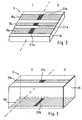
- Fig. 6
- zeigt ein weiteres Ausführungsbeispiel der inFig. 1 dargestellten Mikrowellenleitung bei dem einerster Abschnitt der Mikrowellenleitung eine aufeiner Platine angeordnete Koplanar-Leitung und einzweiter Abschnitt eine auf derselben Platineangeordnete Mikrostreifenleitung ist; und
- Fig. 7
- zeigt ein Ausführungsbeispiel der inFig. 1 dargestellten Mikrowellenleitung bei dem dieMikrowellenleitung eine Koaxialleitung ist, in dieein Kondensator eingefügt ist.
- Fig. 1
- shows schematically a working with microwaves level measuring device;
- Fig. 2
- shows an embodiment of the microwave line shown in Figure 1, in which the microwave line is arranged on a board coplanar line, which is electrically isolated by means arranged on the board capacitors.
- Fig. 3
- shows an embodiment of the microwave line shown in Figure 1 in which the microwave line is arranged on a circuit board microstrip line, which is electrically isolated by means arranged on the board capacitors.
- Fig. 4
- Fig. 12 shows another embodiment of the microwave line shown in Fig. 1, in which a first portion of the microwave line is a coplanar line disposed on a first side of the board and wherein a second section is a coplanar line disposed on a second side of the board;
- Fig. 5
- shows a section through the microwave line of Fig. 3;
- Fig. 6
- shows a further embodiment of the microwave line shown in Figure 1 in which a first portion of the microwave line is a coplanar line arranged on a board and a second portion is a microstrip line arranged on the same board. and
- Fig. 7
- shows an embodiment of the microwave line shown in Fig. 1 in which the microwave line is a coaxial line, in which a capacitor is inserted.
In Fig. 1 ist ein mit Mikrowellen arbeitendes Füllstandsmeßgerätschematisch dargestellt. Die Mikrowellen werdenvon einem Generator 1 erzeugt. Dies ist beispielsweise einPulsradar-Gerät, ein FMCW-Gerät oder ein kontinuierlichschwingender Mikrowellen-Oszillator, der ein Sendesignalerzeugt.In Fig. 1 is a working with microwaves level gaugeshown schematically. The microwaves will begenerated by a
Das Sendesignal wird über eine Sende-Empfangsweiche 5, z.B.einen Richtkoppler, zu einer oberhalb eines Behälters 9angeordneten Antenne 7 übertragen. Von der Sende-Empfangsweiche5 führt eine Mikrowellenleitung 3 zurAntenne 7. Dies ist beispielsweise eine auf einer Platineangeordnete Mikrostreifenleitung, eine Koplanar-Leitung,eine Kombination aus Mikrostreifen- und Koplanar-Leitungoder eine Koaxialleitung.The transmission signal is transmitted via a
Eine Koplanar-Leitung weist drei parallel zueinander aufeiner Platine aufgebrachte planare Leitungsstrukturen auf,von denen eine mittlere eine Signalleitung ist und zweiäußere jeweils Schirmleitungen sind.A coplanar line has three parallel to each otherplanar circuit structures applied to a circuit board,one of which is a signal line and two of themoutside each shielding lines are.
Eine Mikrostreifenleitung weist eine auf einer ersten Seiteeiner Platine angeordnete planare Leitungsstruktur auf, dieals Signalleitung dient. Auf einer der ersten Seitegegenüberliegenden Seite der Platine ist eine weitere,planare Leitungsstruktur aufgebracht, die üblicherweisedeutlich breiter als die Signalleitung ist und alsSchirmleitung dient.A microstrip line has one on a first sidea circuit board arranged planar line structure, theserves as a signal line. On one of the first pageopposite side of the board is another,planar conductive structure applied, usuallyis significantly wider than the signal line and asScreen line is used.
Der Behälter 9 enthält ein Füllgut, dessen Füllstand zubestimmen ist. Von der Antenne 7 ausgesendete Mikrowellenwerden an der Oberfläche des Füllguts reflektiert und dieEchowellen werden von der Antenne 7 aufgenommen. Einentsprechendes Empfangssignal ist über die Sende-Empfangsweiche5 einer Empfangs- und Auswerteschaltung 11zugeführt. Über dieselbe Sende-Empfangsweiche 5 ist das vomGenerator 1 erzeugte Sendesignal der Empfangs- undAuswerteschaltung 11 zugeführt. Aus den beiden Signalenwird der Abstand zwischen Antenne 7 und Füllgutoberflächebestimmt. Da der Abstand zwischen der Antenne 7 und demBehälterboden bekannt ist, ergibt sich hieraus direkt derzu messende Füllstand.The
Die Antenne 7 ist z.B. ein aus einem elektrisch leitendenMaterial, z.B. aus Aluminium oder einem Edelstahl,bestehender Hornstrahler oder eine stabförmige Antenne auseinem Dielektrikum, z.B. aus Polytetrafluorethylen (PTFE).The antenna 7 is e.g. one of an electrically conductiveMaterial, e.g. made of aluminum or a stainless steel,existing horn or a rod-shaped antennaa dielectric, e.g. made of polytetrafluoroethylene (PTFE).
Die letztgenannte Antennenform wird häufig auch alsdielektrischer Stielstrahler bezeichnet.The latter antenna form is often referred to asDielectric Stielstrahler called.
Erfindungsgemäß weist die Mikrowellenleitung 3 einegalvanische Trennung 13 auf. In den Figuren 2 bis 7 sindfünf Ausführungsbeispiele dargestellt. Bei allenAusführungsbeispielen weist die Mikrowellenleitung 3jeweils eine Signalleitung und mindestens eineSchirmleitung auf. In die Signalleitung ist jeweils einerster Kondensator zur galvanische Trennung derSignalleitung eingefügt und in jede Schirmleitung istjeweils ein zweiter Kondensator zur galvanische Trennungder jeweiligen Schirmleitung eingefügt.According to the invention, the
Die Kondensatoren haben eine mechanisch feste Isolation,sie werden im Fehlerfall, z.B. bei hoher Überlast,hochohmig und weisen eine hohe Spannungsfestigkeit, z.B.von 500 V, auf.The capacitors have a mechanically strong insulation,in the event of an error, they are at high overload,high impedance and have a high withstand voltage, e.g.from 500 V, up.
In dem in Fig. 2 dargestellten Ausführungsbeispiel ist dieMikrowellenleitung 3 eine auf einer ersten Seite einerPlatine 15 angeordnete Koplanar-Leitung. Eine der erstenSeite gegenüberliegende zweite Seite der Platine 15 istentweder frei oder mit einer metallischen Beschichtungversehen und mit einem Bezugspotential, z.B. Masse,verbunden. Die Koplanar-Leitung besteht aus drei parallelzueinander verlaufenden auf die Platine 15 aufgebrachtenplanaren Leitungsstrukturen. Die mittlere Leitung dient alsSignalleitung 17a und zu beiden Seiten der Signalleitung17a verläuft jeweils eine Schirmleitung 19a.In the embodiment shown in Fig. 2 is theMicrowave line 3 a on a first side of a
In die Signalleitung 17a ist auf der ersten Seite derPlatine 15 ein erster Kondensator 21a eingefügt, durch deneine galvanische Trennung der Signalleitung 17a erfolgt.In die Schirmleitungen 19a sind auf der ersten Seite derPlatine 15 zweite Kondensatoren 23a eingefügt, durch dieeine galvanische Trennung der Schirmleitungen 19a erfolgt.Die Kondensatoren 21a, 23a sind z.B. handelsübliche fürMikrowellen geeignete auf einer Platine anbringbare auchals Surface-Mounted-Device bezeichnete Bauteile.In the
Durch die ersten und zweiten Kondensatoren 21a, 23a ist dieMikrowellenleitung 3 in einen generator-zugewandtenAbschnitt I und einen antennen-zugewandten Abschnitt IIunterteilt. Auf der generator-zugewandten Seite sind dieSignalleitung 17a und Schirmleitungen 19a erdfrei mit demGenerator 1 verbunden. Durch die Erdfreiheit sindPotentialausgleichsleitungen, z.B. von einer Versorgung zumMeßgerät, weitgehend überflüssig. Auf der antennen-zugewandtenSeite ist die Signalleitung 17a mit einem inder Antenne 7 angeordneten in der Figur nicht dargestelltenErregerelement verbunden. Das Erregerelement dient dazuMikrowellen von der Mikrowellenleitung 3 in die Antenne 7einzukoppeln und umgekehrt von der Antenne 7 aufgenommeneMikrowellen in die Mikrowellenleitung 3 einzukoppeln. DieSchirmleitungen 19a des antennen-zugewandten Abschnitts IIsind mit Erdpotential verbunden. Ist die Antenne 7 eindielektrischer Stielstrahler, so ist dessen metallischeBefestigung mit dem Erdpotential verbunden. Ist die Antenne7 ein Hornstrahler, so ist das metallische Horn mit demErdpotential verbunden.By the first and
Fig. 3 zeigt ein weiteres Ausführungsbeispiel der in Fig. 1dargestellten Mikrowellenleitung 3. Als Mikrowellenleitung3 dient hier eine auf der Platine 15 angeordneteMikrostreifenleitung. Eine Signalleitung 17b ist auf einerersten Seite der Platine 15 angeordnet. Auf der der erstenSeite gegenüberliegenden zweiten Seite der Platine 15 isteine Schirmleitung 19b angeordnet. Die Mikrowellenleitung 3ist auch hier durch erste und zweite Kondensatoren 21b, 23bin zwei Abschnitte I, II unterteilt, nämlich einen erstenmit dem Generator 1 verbundenen Abschnitt I und einenzweiten mit der Antenne 7 verbundenen Abschnitt II. Wie beidem Ausführungsbeispiel von Fig. 2 sind die Kondensatoren21b, 23b auf der Platine 15 angebracht und bewirken einegalvanische Trennung der Signälleitung 17b und derSchirmleitung 19b.FIG. 3 shows a further exemplary embodiment of that in FIG. 1shown
Fig. 4 zeigt ein weiteres Ausführungsbeispiel bei dem dieMikrowellenleitung 3 eine auf einer Platine 15 angeordneteKoplanar-Leitung ist. Die Mikrowellenleitung 3 ist auchhier durch erste und zweite Kondensatoren 21c, 23c in zweiAbschnitte I, II unterteilt, nämlich einen ersten mit demGenerator 1 verbundenen Abschnitt I und einen zweiten mitder Antenne 7 verbundenen Abschnitt II.Fig. 4 shows another embodiment in which theMicrowave line 3 a arranged on a
In dem ersten Abschnitt I sind eine Signalleitung 17c undzwei Schirmleitungen 19c auf der ersten Seite der Platine15 angeordnet. In dem zweiten Abschnitt II sind eineSignalleitung 17d und zwei Schirmleitungen 19d auf derzweiten der ersten Seite gegenüberliegenden Seite derPlatine 15 angeordnet. Die beiden Abschnitte I und IIüberlappen. Die antennen-zugewandten Enden der Signalleitung 17c und der Schirmleitungen 19c des erstenAbschnitts I sind jeweils über den generator-zugewandtenEnden der entsprechenden Signalleitung 17d bzw.Schirmleitung 19d des zweiten Abschnitts II angeordnet. Dieüberlappenden Bereiche schließen jeweils einen dazwischenbefindlichen Bereich der Platine 15 ein.In the first section I are a
Der erste Kondensator 21c, durch den die Signalleitungen17c, 17d miteinander galvanisch getrennt verbunden sind istdurch die überlappenden Bereiche der Signalleitungen 17c,17d des ersten und des zweiten Abschnitts I, II und einendazwischen befindlichen Bereich der Platine 15 gebildet.The first capacitor 21 c, through which the
Die zweiten Kondensatoren 23c, durch die dieSchirmleitungen 19c, 19d miteinander galvanisch getrenntverbunden sind, sind durch die überlappenden Bereiche derjeweiligen Schirmleitungen 19c, 19d des ersten und deszweiten Abschnitts I, II und die dazwischen befindlichenBereiche der Platine 15 gebildet.The
Fig. 5 zeigt einen Schnitt durch die Mikrowellenleitung 3von Fig. 4, aus dem die Überlappung der Abschnitte I und IIund die dadurch gebildeten Kondensatoren, am Beispiel derSchirmleitungen 19c, 19d und des zweiten Kondesators 23c,gezeigt sind.5 shows a section through the
In Abhängigkeit von den Eigenschaften, insb. der Frequenzbzw. des Frequenzspektrums, der zu übertragendenMikrowellen kann die Geometrie der Enden derSignalleitungen und der Schirmleitungen besonders angepaßtsein. So lassen sich z.B. breitbandige Übertragungseigenschaften erzielen, indem die Enden vorzugsweisedeutlich breiter als die eigentlichen Leitungen ausgebildetsind und die Form von Viertelkreises aufweisen. Auch istdurch diese Geometrie der Impedanzsprung an dem Übergangweniger groß und es wird somit weniger Mikrowellenstrahlungreflektiert.Depending on the characteristics, in particular the frequencyor the frequency spectrum to be transmittedMicrowaves can change the geometry of the ends of theSignal lines and the shield lines specially adaptedbe. Thus, for example, broadband transmission characteristicsAchieve by the ends preferablysignificantly wider than the actual lines formedare and have the shape of quarter circle. Also isthrough this geometry, the impedance jump at the transitionless large and thus less microwave radiationreflected.
Ein Vorteil der letztbeschriebenen Mikrowellenleitung 3ist, daß keine zusätzlichen Kondensatoren erforderlichsind, sondern stattdessen die ohnehin vorhandene Platine 15genutzt wird.An advantage of the last-described
Auf der generator-zugewandten Seite sind die Signalleitung17c und Schirmleitungen 19c erdfrei mit dem Generator 1verbunden. Auf der antennen-zugewandten Seite ist dieSignalleitung 17d mit einem in der Antenne 7 angeordnetenin der Figur nicht dargestellten Erregerelement verbunden.Auch hier dient das Erregerelement dazu Mikrowellen von derMikrowellenleitung 3 in die Antenne 7 einzukoppeln undumgekehrt von der Antenne 7 aufgenommene Mikrowellen in dieMikrowellenleitung 3 einzukoppeln. Die Schirmleitungen 19ddes antennen-zugewandten Abschnitts II sind mitErdpotential verbunden. Ist die Antenne 7 eindielektrischer Stielstrahler, so ist dessen metallischeBefestigung mit dem Erdpotential verbunden. Ist die Antenne7 ein Hornstrahler, so ist das metallische Horn mit demErdpotential verbunden.On the generator side are the
Bei dem in Fig. 6 dargestellten Ausführungsbeispiel weistdie Mikrowellenleitung 3 einen ersten mit dem Generator 1verbundenen Abschnitt I auf, der als Koplanar-Leitung ausgebildet ist. Ein zweiter mit der Antenne 7 verbundenerAbschnitt II der Mikrowellenleitung 3 ist alsMikrostreifenleitung ausgebildet. Beide Abschnitte I, IIsind auf derselben Platine 15 angeordnet.In the embodiment shown in Fig. 6 showsthe microwave line 3 a first with the generator. 1connected section I, acting as a coplanar lineis trained. A second connected to the antenna 7Section II of the
Eine Signalleitung 17e ist sowohl im ersten als auch imzweiten Abschnitt I, II auf der ersten Seite der Platine 15angeordnet. Im ersten Abschnitt I ist zu jeder Seite derSignalleitung 17e je eine Schirmleitung 19e angeordnet.A
Auf der zweiten Seite der Platine 15 ist in dem zweitenAbschnitt II eine Schirmleitung 19f angeordnet. Diesebesteht aus einem metallisch beschichteten Bereich derzweiten Seite der Platine 15. Der erste und der zweiteAbschnitt I und II überlappen. Ein antennen-zugewandtesEnde jeder der auf der ersten Seite der Platine 15angeordneten Schirmleitungen 19e überdeckt somit denmetallisch beschichteten Bereich, der die Schirmleitung 19fdes zweiten Abschnitts II bildet.On the second side of the
Anstelle einer einzigen großflächigen Schirmleitung 19fkönnen selbstverständlich auch zwei oder mehr einzelne z.B.streifenförmige Schirmleitungen auf der zweiten Seite derPlatine 15 aufgebracht sein. Es muß lediglich gewährleistetsein, daß ein ausreichender Überlapp zwischen denSchirmleitungen 19e des ersten Abschnitts I und der bzw.den Schirmleitungen des zweiten Abschnitts II besteht.Instead of a single large-
Der erste Kondensator 21e ist auf der ersten Seite derPlatine 15 in die Signalleitung 17e eingefügt. Die zweitenkondensatoren 23e sind durch die überlappenden Bereiche der Schirmleitungen 19e des ersten und 19f des zweitenAbschnitts II und dazwischen befindliche Bereiche derPlatine 15 gebildet.The
Die antennen-zugewandten Enden der Schirmleitungen 19e sindgegenüber den eigentlichen Schirmleitungen 19e verbreitertund weisen die Form eines Viertelkreises auf. Hierdurchwird erreicht, daß der Impedanzsprung für Mikrowellenstrahlungan dem Übergang vom ersten zum zweiten Abschnittweniger groß ist und somit weniger Mikrowellenstrahlungreflektiert wird. Auch wird der Frequenzbereich, indemgünstige Übertragungseigenschaften vorliegen durch dieseGeometrie verbreitert. Andere Geometrien der Enden, z.B.solche, die an eine spezielle zu verwendendeMikrowellenstrahlung angepaßt sind, sind ebenfallseinsetzbar.The antenna-facing ends of the shield lines 19e arewidened compared to the actual shield lines 19eand have the shape of a quarter circle. herebyis achieved that the impedance jump for microwave radiationat the transition from the first to the second sectionis less large and thus less microwave radiationis reflected. Also, the frequency range is increased byfavorable transmission properties are present through thisGeometry widened. Other geometries of the ends, e.g.those that are to be used on a specialMicrowave radiation are adapted, are alsoused.
Durch die ersten und zweiten Kondensatoren 21e, 23e ist dieMikrowellenleitung 3 in einen generator-zugewandtenAbschnitt I und einen antennen-zugewandten Abschnitt IIunterteilt. Auf der generator-zugewandten Seite sind dieSignalleitung 17e und Schirmleitungen 19e erdfrei mit demGenerator 1 verbunden. Auf der antennen-zugewandten Seiteist die Signalleitung 17e genau wie bei den vorgenanntenAusführungsbeispielen mit einem in der Antenne 7angeordneten in der Figur nicht dargestelltenErregerelement verbunden.By the first and
Selbstverständlich kann die beschriebene Mikrowellenleitung3 von Fig. 6 auch in umgekehrter Orientierung verwendetwerden. Entsprechend wäre dann der als Koplanar-Leitung ausgebildete erste Abschnitt I mit der Antenne 7 und derals Mikrostreifenleitung ausgebildete zweite Abschnitt IIerdfrei mit dem Generator 1 zu verbinden.Of course, the described
Bei dem in Fig. 7 dargestellten Ausführungsbeispiel ist dieMikrowellenleitung 3 eine Koaxialleitung. Sie weist einenmit dem Generator 1 verbundenen ersten Abschnitt I undeinen mit der Antenne 7 verbundenen zweiten Abschnitt IIauf. In beiden Abschnitten weist die Koaxialleitung eineSignalleitung 17g, 17h und eine diese koaxial umgebendeSchirmleitung 19g, 19h auf.In the embodiment shown in Fig. 7, theMicrowave line 3 a coaxial line. She has oneconnected to the
Zwischen dem ersten und dem zweiten Abschnitt I, II isteine Platte 33 aus einem Isolator, z.B. aus Aluminiumoxid,angeordnet. Die Platte 33 weist zwei in deren Mitteeinander gegenüberliegend angeordnete Elektroden 35, 37auf, die einen ersten Kondensator 21g bilden, durch den dieSignalleitungen 17g, 17h galvanisch getrennt sind. Einzweiter Kondensator 23g ist durch zwei jeweils auf einemäußeren Rand der isolierenden Platte 33 einandergegenüberliegend angordnete Ringelektroden 39, 41 gebildet.Durch diesen sind die Schirmleitungen 19g, 19h galvanischgetrennt.Between the first and the second section I, II isa
Die generator-zugewandte in der Mitte der Platte 33angeordnete Elektrode 35 ist mit der Signalleitung 17g desersten Abschnitts I und die antennen-zugewandte Elektrode37 ist mit der Signalleitung 17h des zweiten Abschnitts IIder Mikrowellenleitung 3 verbunden. Analog ist diegenerator-zugewandte Ringelektrode 39 mit der Schirmleitung17g des ersten Abschnitts I und eine antennen-zugewandte Ringelektrode 41 ist mit der Schirmleitung 17h des zweitenAbschnitts II der Mikrowellenleitung 3 verbunden.The generator-facing in the middle of the
Der erste Abschnitt I ist beispielsweise eine im Handelerhältliche Koaxialleitung, die außen von einer Isolation25 umgeben ist.For example, the first section I is one commercially availableavailable coaxial cable, the outside of an
Innenleiter von handelsüblichen Koaxialleitungen weiseneinen geringen Durchmesser auf. Aus diesem Grund ist dieSignalleitung 17g des ersten Abschnitts I endseitig z.B.mit einem Hohlniet 43 versehen. Dieser weist einenrohrfömigen Bereich auf, der das freie Ende derSignalleitung 17g eng umschließt und mit dieser z.B. übereine Lötung elektrisch leitend verbunden ist. Eine sichradial nach außen erstreckende Schulter des Hohlniet 43 istelektrisch leitend, z.B. ebenfalls über eine Lötverbindung,mit der generator-zugewandten Elektrode 35 des erstenKondensators 21g verbunden.Point inner conductor of commercially available coaxial cablesa small diameter. That is why theSignal line 17g of the first section I at the end, e.g.provided with a hollow rivet 43. This one has onerohrfömigen area on which the free end of theSignal line 17g engages tightly and with this example. abovea solder is electrically connected. One yourselfradially outwardly extending shoulder of the rivet 43 iselectrically conductive, e.g. also via a solder connection,with the generator-facing
An dem antennen-zugewandten Ende des ersten Abschnitts Iweist die Mikrowellenleitung 3 einen Abschnitt ohneIsolation auf. In diesen Abschnitt ist in die Schirmleitung19g ein Stützrohr 29 eingesteckt. Dadurch bedingt ist derDurchmesser des antennen-zugewandten Endes derSchirmleitung 19g geringfügig aufgeweitet. Der abisolierteAbschnitt der Mikrowellenleitung ist in einem Metallrohr 27angeordnet. Dieses ist über das Leitungsende gestülpt undanschießend verpreßt, so daß das Ende der Schirmleitung 19gzwischen dem Metallrohr 27 und dem Stützrohr 29 eingespanntist. Es besteht eine elektrisch leitende Verbindungzwischen dem Stützrohr 29 und der Schirmleitung 19g.At the antenna-facing end of the first section Ithe
An das Stützrohr 29 ist in antennen-zugewandter Richtungeine Metallhülse 31 mit geringfügig größerem Durchmesserangeformt. Eine ringscheibenförmige Stirnfläche derMetallhülse 31 liegt auf der generator-zugewandtenRingelektrode 39 des zweiten Kondensators 23g auf. Esbesteht somit über das Stützrohr 29 und die Metallhülse 31eine elektrisch leitende Verbindung zwischen derSchirmleitung 19g und der generator-zugewandtenRingelektrode 39.To the
Die auf der antennen-zugewandten Seite der Platte 33angeordnete Mikrowellenleitung 3 kann genau wie dieMikrowellenleitung 3 des ersten Abschnitts I einehandelsübliche Koaxialleitung sein. In diesem Fall kannderen elektrischer Anschluß an die Elektrode 37 und dieRingelektrode 41 ebenfalls auf die oben beschriebene Weiseerfolgen. Die Anordnung wäre dann symmetrisch zu der Platte33.The on the antenna-facing side of the plate 33rdarranged
Bei dem in Fig. 7 gezeigten Ausführungsbeispiel weist derAbschnitt II der Mikrowellenleitung 3 einen Metallstift alsSignalleitung 17h auf. Diese liegt mit einer kreisförmigenStirnfläche auf der in der Mitte der Platte 33 angeordnetenantennen-zugewandten Elektrode 37 auf. Als Schirmleitung19h ist eine Metallhülse, z.B. aus einem Edelstahl,vorgesehen, die mit einer ringscheiben-förmigen Stirnflächeauf der antennen-zugewandten Ringelektrode 41 aufliegt.Zwischen der Elektrode 37 und der Signalleitung 17h, sowiezwischen der Ringelektrode 41 und der Schirmleitung 19h besteht eine elektrisch leitende Verbindung, z.B. eineLötverbindung.In the embodiment shown in Fig. 7, theSection II of the microwave line 3 a metal pin as
Vorzugsweise ist ein zwischen der Schirmleitung 19h und derSignalleitung 17h auf der antennen-zugewandten Seite derPlatte 33 bestehender Hohlaum 45 mit einem Isolator, z.B.mit Glas, ausgefüllt. Hierdurch ist eine druckfesteDurchführung gegeben.Preferably, one between the
Die Signalleitung 17h ist z.B. elektrisch leitend mit einemin der Antenne 7 angeordneten Erregerstift verbunden.The
Die Platte 33 mit dem ersten und dem zweiten Kondensator21g, 23g als auch die daran angrenzenden Bereiche, in denender Anschluß der beiden Abschnitte I, II derMikrowellenleitung 3 an den ersten und den zweitenKondensator 21g, 23g erfolgt, ist von einer Isolation 47,z.B. aus Kunststoff, umgeben. In dem Ausführungsbeispielvon Fig. 7 weist die Isolation 47 in einem antennen-zugewandtenAbschnitt ein Innengewinde 49 auf, mittelsdessen sie auf ein auf der Schirmleitung 19h angeordnetesAußengewinde geschraubt ist. Andere Arten der Befestigung,z.B. mittels Schnapp- oder Bajonettverschlüssen sindebenfalls möglich.The
Die Schirmleitung 19h des zweiten Abschnitts II ist mit demErdpotential verbunden. Der generator-zugewandte AbschnittI der Mikrowellenleitung 3 ist dagegen erdfrei mit demMikrowellengenerator 1 verbunden.The
Die beschriebenen Mikrowellenleitungen 3 mit galvanischerTrennung können jeweils auch nachträglich in einbestehendes mit Mikrowellen arbeitendes Füllstandsmeßgeräteingebracht werden.The described
Die Erfindung ist auch bei solchen mit Mikrowellenarbeitenden Füllstandsmeßgeräten einsetzbar, die nicht nureine einzige als Sender und als Empfänger dienende Antenne,sondern zwei oder mehr Antennen aufweisen. Jede zu einerder Antennen führende Mikrowellenleitung wäre dann miteiner der vorgehend beschriebenene galvanischen Trennungenauszustatten.The invention is also in those with microwavesworking Füllstandsmeßgeräten used, not onlya single antenna serving as transmitter and receiver,but have two or more antennas. Each one to onethe antennas leading microwave line would be withone of the previously described galvanic separationsequip.
Claims (7)
- A level meter which operates using microwaves, comprising:characterised bya generator (1) for the generation of microwaves,at least one antenna (7) for the transmission and reception ofmicrowaves,a receiving and evaluation unit (11) which determines a level onthe basis of the microwaves received and generates an outputsignal which corresponds to the level, anda microwave line (3)which leads from the generator (1) to the antenna (7) andwhich has a signal line (17a, 17b, 17c, 17d, 17e, 17g, 17h)and at least one shield line (19a, 19b, 19c, 19d, 19e, 19f,19g, 19h),a first capacitor (21a, 21b, 21c, 21e, 21g) inserted into thesignal line (17a, 17b, 17c, 17d, 17e, 17g, 17h) for the electricaldivision thereof,and by a second capacitor (23a, 23b, 23c, 23e, 23g) insertedinto each of the at least one shield line (19a, 19b, 19c, 19d, 19e,19f, 19g, 19h) for the electrical division of each respective shieldline (19a, 19b, 19c, 19d, 19e, 19f, 19g, 19h).
- A level meter, which operates using microwaves, according to claim1, whereinthe microwave line (3) is a coplanar line arranged on a first sideof a board (15),in which line (3) a shield line (19a) is arranged on either sideof the signal line (17a), andthe first and second capacitors (21a, 23a) are componentsarranged on the first side of the board (15).
- A level meter, which operates using microwaves, according to claim1, whereinthe microwave line (3) is a microstrip line arranged on a board(15),in which line (3) a signal line (17b) and a first capacitor (21b)are arranged on a first side of the board (15) andin which line (3) at least one shield line (19b) and at leastone second capacitor (23b) are arranged on a second side ofthe board (15) opposite the first side.
- A level meter, which operates using microwaves, according to claim1, whereinthe microwave line (3) is a coplanar line arranged on a board(15),in which line (3) a shield line (19c, 19d) is arranged on eitherside of each respective signal line (17c, 17d) andwhich line (3) has a first portion (I) connected to thegenerator (1),in which portion (I) the signal line (17c) and the shieldlines (19c) are arranged on a first side of the board (15),andwhich line (3) has a second portion (II) connected to theantenna (7),in which portion (II) the signal line (17d) and the shieldlines (19d) are arranged on a second side of the board (15)opposite the first side,wherein the first and second portions (I, II) of the microwaveline (3) overlap,wherein the first capacitor (21c) is formed by overlappingregions of the signal lines (17c, 17d) of the first and the secondportion (I, II) and a region of the board (15) locatedtherebetween, andwherein the second capacitors (23c) are formed by overlappingregions of the shield lines (19c, 19d) of the first and the secondportion (I, II) and regions of the board (15) located therebetween.
- A level meter, which operates using microwaves, according to claim1, whereinthe microwave line (3) has a first portion (I)in which the microwave line (3) is a coplanar line arrangedon a board ( 15),in which line (3) a signal line (17e) is arranged on a firstside of the board (15) and a shield line ( 19e) is arrangedon either side of the signal line (17e),the microwave line (3) has a second portion (II)in which the microwave line (3) is a microstrip linewhich has a signal line (17e) extending on the first side ofthe board (15) and at least one shield line (19f) arrangedon a second side of the board (15) opposite the first side,wherein the first and second portions (I, II) of the microwaveline (3) overlap,wherein the first capacitor (21e) is arranged on the first side ofthe board (15),wherein the second capacitors (23e) are formed by overlappingregions of the shield lines (19e, 19f) of the first and the secondportion (I, II) and regions of the board (15) located therebetween,andwherein either the first portion (I) is connected to the antenna(7) and the second portion (II) is connected to the generator (1)or, conversely, the second portion (II) is connected to theantenna (7) and the first portion (I) is connected to thegenerator (1).
- A level meter, which operates using microwaves, according to claim1, whereinthe microwave line (3) is a coaxial linewhich has a first portion (I) connected to the generator (1)and a second portion (II) connected to the antenna (7),a plate (33) comprising an insulator is arranged between thefirst and the second portion (I, II),the first capacitor (21g) has two electrodes (35, 37) which areeach arranged in the middle of the plate (33) so as to lieopposite one another,of which a generator-facing electrode (35) is connected to thesignal line (17g) of the first portion (I) and an antenna-facingelectrode (37) is connected to the signal line (17h) of thesecond portion (II) of the microwave line (3), andthe second capacitor (23g) has two ring electrodes (39, 41)which are each arranged on an outer edge of the plate (33) so asto lie opposite one another,of which a generator-facing ring electrode (39) is connectedto the shield line (19g) of the first portion (I) and an antenna-facingring electrode (41) is connected to the shield line (19h)of the second portion (II) of the microwave line (3).
- A level meter, which operates using microwaves, according to claim6, wherein a cavity (45) existing between the shield line (19g) andthe signal line (17g) of the second portion (II) of the microwave line(3) is filled with an insulator, especially glass.
Priority Applications (2)
| Application Number | Priority Date | Filing Date | Title |
|---|---|---|---|
| DE59712260TDE59712260D1 (en) | 1997-06-06 | 1997-06-06 | Microwave level gauge |
| EP19970109195EP0882955B1 (en) | 1997-06-06 | 1997-06-06 | Level measuring apparatus using microwaves |
Applications Claiming Priority (1)
| Application Number | Priority Date | Filing Date | Title |
|---|---|---|---|
| EP19970109195EP0882955B1 (en) | 1997-06-06 | 1997-06-06 | Level measuring apparatus using microwaves |
Publications (2)
| Publication Number | Publication Date |
|---|---|
| EP0882955A1 EP0882955A1 (en) | 1998-12-09 |
| EP0882955B1true EP0882955B1 (en) | 2005-04-06 |
Family
ID=8226886
Family Applications (1)
| Application Number | Title | Priority Date | Filing Date |
|---|---|---|---|
| EP19970109195Expired - LifetimeEP0882955B1 (en) | 1997-06-06 | 1997-06-06 | Level measuring apparatus using microwaves |
Country Status (2)
| Country | Link |
|---|---|
| EP (1) | EP0882955B1 (en) |
| DE (1) | DE59712260D1 (en) |
Cited By (71)
| Publication number | Priority date | Publication date | Assignee | Title |
|---|---|---|---|---|
| US7998139B2 (en) | 2007-04-25 | 2011-08-16 | Vivant Medical, Inc. | Cooled helical antenna for microwave ablation |
| US8034052B2 (en) | 2006-05-05 | 2011-10-11 | Covidien Ag | Apparatus and method for electrode thermosurgery |
| US8062290B2 (en) | 2004-10-08 | 2011-11-22 | Covidien Ag | Electrosurgical system employing multiple electrodes |
| US8093500B2 (en) | 2007-06-18 | 2012-01-10 | Vivant Medical, Inc. | Microwave cable cooling |
| US8156632B2 (en) | 2007-01-19 | 2012-04-17 | Tyco Healthcare Group Lp | Thermal and electrical conductivity probes and methods of making the same |
| US8188435B2 (en) | 2010-06-03 | 2012-05-29 | Tyco Healthcare Group Lp | Specific absorption rate measurement and energy-delivery device characterization using thermal phantom and image analysis |
| US8313486B2 (en) | 2010-01-29 | 2012-11-20 | Vivant Medical, Inc. | System and method for performing an electrosurgical procedure using an ablation device with an integrated imaging device |
| US8323275B2 (en) | 2009-06-19 | 2012-12-04 | Vivant Medical, Inc. | Laparoscopic port with microwave rectifier |
| US8377057B2 (en) | 2004-10-08 | 2013-02-19 | Covidien Ag | Cool-tip combined electrode introducer |
| US8409188B2 (en) | 2010-03-26 | 2013-04-02 | Covidien Lp | Ablation devices with adjustable radiating section lengths, electrosurgical systems including same, and methods of adjusting ablation fields using same |
| USD680220S1 (en) | 2012-01-12 | 2013-04-16 | Coviden IP | Slider handle for laparoscopic device |
| US8473077B2 (en) | 2009-09-16 | 2013-06-25 | Covidien Lp | Perfused core dielectrically loaded dipole microwave antenna probe |
| US8480666B2 (en) | 2007-01-31 | 2013-07-09 | Covidien Lp | Thermal feedback systems and methods of using the same |
| US8480665B2 (en) | 2007-09-07 | 2013-07-09 | Covidien Lp | Cool tip junction |
| US8491580B2 (en) | 2007-11-27 | 2013-07-23 | Covidien Lp | Targeted cooling of deployable microwave antenna and methods of use |
| US8512329B2 (en) | 2008-08-25 | 2013-08-20 | Covidien Lp | Microwave antenna assembly having a dielectric body portion with radial partitions of dielectric material |
| US8535340B2 (en) | 2009-10-21 | 2013-09-17 | Covidien Lp | Methods for ultrasonic tissue sensing and feedback |
| US8568404B2 (en) | 2010-02-19 | 2013-10-29 | Covidien Lp | Bipolar electrode probe for ablation monitoring |
| US8652127B2 (en) | 2010-05-26 | 2014-02-18 | Covidien Lp | System and method for chemically cooling an ablation antenna |
| US8667674B2 (en) | 2008-06-09 | 2014-03-11 | Covidien Lp | Surface ablation process with electrode cooling methods |
| US8672933B2 (en) | 2010-06-30 | 2014-03-18 | Covidien Lp | Microwave antenna having a reactively-loaded loop configuration |
| US8679108B2 (en) | 2009-02-20 | 2014-03-25 | Covidien Lp | Leaky-wave antennas for medical applications |
| US8728067B2 (en) | 2010-03-08 | 2014-05-20 | Covidien Lp | Microwave antenna probe having a deployable ground plane |
| US8740893B2 (en) | 2010-06-30 | 2014-06-03 | Covidien Lp | Adjustable tuning of a dielectrically loaded loop antenna |
| US8745846B2 (en) | 2011-09-20 | 2014-06-10 | Covidien Lp | Method of manufacturing handheld medical devices including microwave amplifier unit |
| US8745854B2 (en) | 2009-09-09 | 2014-06-10 | Covidien Lp | Method for constructing a dipole antenna |
| US8801709B2 (en) | 2008-02-07 | 2014-08-12 | Covidien Lp | Endoscopic instrument for tissue identification |
| US8832927B2 (en) | 2009-03-10 | 2014-09-16 | Covidien Lp | Method of manufacturing surgical antennas |
| US8852180B2 (en) | 2009-10-28 | 2014-10-07 | Covidien Lp | System and method for monitoring ablation size |
| US8882759B2 (en) | 2009-12-18 | 2014-11-11 | Covidien Lp | Microwave ablation system with dielectric temperature probe |
| US8894640B2 (en) | 2009-09-24 | 2014-11-25 | Covidien Lp | Optical detection of interrupted fluid flow to ablation probe |
| US8932281B2 (en) | 2011-01-05 | 2015-01-13 | Covidien Lp | Energy-delivery devices with flexible fluid-cooled shaft, inflow/outflow junctions suitable for use with same, and systems including same |
| US8966981B2 (en) | 2003-10-30 | 2015-03-03 | Covidien Ag | Switched resonant ultrasonic power amplifier system |
| US8969722B2 (en) | 2008-01-23 | 2015-03-03 | Covidien Lp | Thermally tuned coaxial cable for microwave antennas |
| US8968297B2 (en) | 2011-07-19 | 2015-03-03 | Covidien Lp | Microwave and RF ablation system and related method for dynamic impedance matching |
| US8992413B2 (en) | 2011-05-31 | 2015-03-31 | Covidien Lp | Modified wet tip antenna design |
| US9011421B2 (en) | 2011-01-05 | 2015-04-21 | Covidien Lp | Energy-delivery devices with flexible fluid-cooled shaft, inflow/outflow junctions suitable for use with same, and systems including same |
| US9017319B2 (en) | 2011-01-05 | 2015-04-28 | Covidien Lp | Energy-delivery devices with flexible fluid-cooled shaft, inflow/outflow junctions suitable for use with same, and systems including same |
| US9023025B2 (en) | 2011-09-20 | 2015-05-05 | Covidien Lp | Handheld medical devices including microwave amplifier unit at device handle |
| US9024237B2 (en) | 2009-09-29 | 2015-05-05 | Covidien Lp | Material fusing apparatus, system and method of use |
| US9028476B2 (en) | 2011-02-03 | 2015-05-12 | Covidien Lp | Dual antenna microwave resection and ablation device, system and method of use |
| US9028482B2 (en) | 2011-07-19 | 2015-05-12 | Covidien Lp | Microwave and RF ablation system and related method for dynamic impedance matching |
| US9033973B2 (en) | 2011-08-30 | 2015-05-19 | Covidien Lp | System and method for DC tissue impedance sensing |
| US9033970B2 (en) | 2011-09-20 | 2015-05-19 | Covidien Lp | Handheld medical devices including microwave amplifier unit at device handle |
| US9039692B2 (en) | 2011-09-20 | 2015-05-26 | Covidien Lp | Handheld medical devices including microwave amplifier unit at device handle |
| US9039693B2 (en) | 2011-09-20 | 2015-05-26 | Covidien Lp | Handheld medical devices including microwave amplifier unit at device handle |
| US9066681B2 (en) | 2012-06-26 | 2015-06-30 | Covidien Lp | Methods and systems for enhancing ultrasonic visibility of energy-delivery devices within tissue |
| US9113888B2 (en) | 2004-10-08 | 2015-08-25 | Covidien Ag | Electrosurgical system employing multiple electrodes and method thereof |
| US9113900B2 (en) | 1998-10-23 | 2015-08-25 | Covidien Ag | Method and system for controlling output of RF medical generator |
| US9119624B2 (en) | 2006-04-24 | 2015-09-01 | Covidien Ag | ARC based adaptive control system for an electrosurgical unit |
| US9190704B2 (en) | 2007-07-30 | 2015-11-17 | Covidien Lp | Electrosurgical systems and printed circuit boards for use therewith |
| US9192437B2 (en) | 2009-05-27 | 2015-11-24 | Covidien Lp | Narrow gauge high strength choked wet tip microwave ablation antenna |
| US9192422B2 (en) | 2011-07-19 | 2015-11-24 | Covidien Lp | System and method of matching impedances of an electrosurgical generator and/or a microwave generator |
| US9192426B2 (en) | 2012-06-26 | 2015-11-24 | Covidien Lp | Ablation device having an expandable chamber for anchoring the ablation device to tissue |
| US9192440B2 (en) | 2010-02-05 | 2015-11-24 | Covidien Lp | Electrosurgical devices with choke shorted to biological tissue |
| US9198724B2 (en) | 2011-04-08 | 2015-12-01 | Covidien Lp | Microwave tissue dissection and coagulation |
| US9241762B2 (en) | 2010-06-03 | 2016-01-26 | Covidien Lp | Specific absorption rate measurement and energy-delivery device characterization using image analysis |
| US9271791B2 (en) | 2009-10-28 | 2016-03-01 | Covidien Lp | System and method for monitoring ablation size |
| US9276367B2 (en) | 2009-11-17 | 2016-03-01 | Covidien Lp | Method of manurfacturing an electromagnetic energy delivery device |
| US9271796B2 (en) | 2008-06-09 | 2016-03-01 | Covidien Lp | Ablation needle guide |
| US9332959B2 (en) | 2012-06-26 | 2016-05-10 | Covidien Lp | Methods and systems for enhancing ultrasonic visibility of energy-delivery devices within tissue |
| US9370399B2 (en) | 2009-09-29 | 2016-06-21 | Covidien Lp | Flow rate monitor for fluid cooled microwave ablation probe |
| US9370392B2 (en) | 2012-10-02 | 2016-06-21 | Covidien Lp | Heat-sensitive optical probes |
| US9377367B2 (en) | 2010-06-03 | 2016-06-28 | Covidien Lp | Specific absorption rate measurement and energy-delivery device characterization using thermal phantom and image analysis |
| US9439712B2 (en) | 2012-07-12 | 2016-09-13 | Covidien Lp | Heat-distribution indicators, thermal zone indicators, electrosurgical systems including same and methods of directing energy to tissue using same |
| US9468492B2 (en) | 2010-06-03 | 2016-10-18 | Covidien Lp | Specific absorption rate measurement and energy-delivery device characterization using image analysis |
| US9492190B2 (en) | 2011-02-09 | 2016-11-15 | Covidien Lp | Tissue dissectors |
| US9522033B2 (en) | 2012-10-02 | 2016-12-20 | Covidien Lp | Devices and methods for optical detection of tissue contact |
| US9526568B2 (en) | 2012-05-31 | 2016-12-27 | Covidien Lp | Drug-delivery device for use with ablation device |
| US9561076B2 (en) | 2010-05-11 | 2017-02-07 | Covidien Lp | Electrosurgical devices with balun structure for air exposure of antenna radiating section and method of directing energy to tissue using same |
| US9579150B2 (en) | 2011-04-08 | 2017-02-28 | Covidien Lp | Microwave ablation instrument with interchangeable antenna probe |
Families Citing this family (167)
| Publication number | Priority date | Publication date | Assignee | Title |
|---|---|---|---|---|
| DE10019129A1 (en) | 2000-04-18 | 2001-10-25 | Endress Hauser Gmbh Co | Microwave tank level sensor, has tapered coupling unit avoids cavity resonances |
| DE10045997B4 (en)* | 2000-09-18 | 2011-04-14 | Vega Grieshaber Kg | Nozzle for a guided on the principle of the guided microwave level measuring device with single wire |
| DE10102439B9 (en)* | 2001-01-19 | 2012-06-21 | Vega Grieshaber Kg | Level gauge and method for transmitting and receiving electromagnetic waves having a frequency of less than 3 GHz via a single antenna device |
| US6677891B2 (en) | 2001-01-19 | 2004-01-13 | Vega Grieshaber Kg | Method and device for transmitting and receiving electromagnetic waves |
| US6891513B2 (en) | 2001-11-26 | 2005-05-10 | Vega Greishaber, Kg | Antenna system for a level measurement apparatus |
| US6778044B2 (en) | 2002-01-23 | 2004-08-17 | Vega Grieshaber Kg | Coaxial line plug-in connection with integrated galvanic separation |
| US7197363B2 (en) | 2002-04-16 | 2007-03-27 | Vivant Medical, Inc. | Microwave antenna having a curved configuration |
| DE102004038574A1 (en)* | 2004-08-06 | 2006-03-16 | Endress + Hauser Gmbh + Co. Kg | Device for transmitting broadband radio frequency signals |
| US7628786B2 (en) | 2004-10-13 | 2009-12-08 | Covidien Ag | Universal foot switch contact port |
| DE102005036715A1 (en)* | 2005-08-04 | 2007-02-15 | Vega Grieshaber Kg | Fill level radar for determining fill level in tank, has separation element arranged directly at aerial for isolating aerial from feed device |
| US8711049B2 (en) | 2005-08-04 | 2014-04-29 | Vega Grieshaber Kg | Potential separation for filling level radar |
| DE102006015659A1 (en) | 2006-01-27 | 2007-08-09 | Vega Grieshaber Kg | Electrical isolation for radar measuring level in vessel, includes optical isolation in electronics unit to separate signals in first section from signals in second section |
| US8353902B2 (en) | 2008-01-31 | 2013-01-15 | Vivant Medical, Inc. | Articulating ablation device and method |
| US9949794B2 (en) | 2008-03-27 | 2018-04-24 | Covidien Lp | Microwave ablation devices including expandable antennas and methods of use |
| US8343149B2 (en) | 2008-06-26 | 2013-01-01 | Vivant Medical, Inc. | Deployable microwave antenna for treating tissue |
| US8172836B2 (en) | 2008-08-11 | 2012-05-08 | Tyco Healthcare Group Lp | Electrosurgical system having a sensor for monitoring smoke or aerosols |
| US8251987B2 (en) | 2008-08-28 | 2012-08-28 | Vivant Medical, Inc. | Microwave antenna |
| US8403924B2 (en) | 2008-09-03 | 2013-03-26 | Vivant Medical, Inc. | Shielding for an isolation apparatus used in a microwave generator |
| US8394086B2 (en) | 2008-09-03 | 2013-03-12 | Vivant Medical, Inc. | Microwave shielding apparatus |
| US8377053B2 (en) | 2008-09-05 | 2013-02-19 | Covidien Lp | Electrosurgical apparatus with high speed energy recovery |
| US8242782B2 (en) | 2008-09-30 | 2012-08-14 | Vivant Medical, Inc. | Microwave ablation generator control system |
| US9277969B2 (en) | 2009-04-01 | 2016-03-08 | Covidien Lp | Microwave ablation system with user-controlled ablation size and method of use |
| US8246615B2 (en) | 2009-05-19 | 2012-08-21 | Vivant Medical, Inc. | Tissue impedance measurement using a secondary frequency |
| US8552915B2 (en) | 2009-06-19 | 2013-10-08 | Covidien Lp | Microwave ablation antenna radiation detector |
| US8328799B2 (en) | 2009-08-05 | 2012-12-11 | Vivant Medical, Inc. | Electrosurgical devices having dielectric loaded coaxial aperture with distally positioned resonant structure |
| US8328800B2 (en) | 2009-08-05 | 2012-12-11 | Vivant Medical, Inc. | Directive window ablation antenna with dielectric loading |
| US8328801B2 (en) | 2009-08-17 | 2012-12-11 | Vivant Medical, Inc. | Surface ablation antenna with dielectric loading |
| US8469953B2 (en) | 2009-11-16 | 2013-06-25 | Covidien Lp | Twin sealing chamber hub |
| US10039588B2 (en) | 2009-12-16 | 2018-08-07 | Covidien Lp | System and method for tissue sealing |
| US8764744B2 (en) | 2010-01-25 | 2014-07-01 | Covidien Lp | System for monitoring ablation size |
| US9113927B2 (en) | 2010-01-29 | 2015-08-25 | Covidien Lp | Apparatus and methods of use for treating blood vessels |
| US8968288B2 (en) | 2010-02-19 | 2015-03-03 | Covidien Lp | Ablation devices with dual operating frequencies, systems including same, and methods of adjusting ablation volume using same |
| US8777939B2 (en) | 2010-02-26 | 2014-07-15 | Covidien Lp | Self-tuning microwave ablation probe |
| US8617153B2 (en) | 2010-02-26 | 2013-12-31 | Covidien Lp | Tunable microwave ablation probe |
| US8454590B2 (en) | 2010-02-26 | 2013-06-04 | Covidien Lp | Enhanced lossless current sense circuit |
| US20110213353A1 (en) | 2010-02-26 | 2011-09-01 | Lee Anthony C | Tissue Ablation System With Internal And External Radiation Sources |
| US8672923B2 (en) | 2010-03-11 | 2014-03-18 | Covidien Lp | Automated probe placement device |
| US9028474B2 (en) | 2010-03-25 | 2015-05-12 | Covidien Lp | Microwave surface coagulator with retractable blade |
| US10039601B2 (en) | 2010-03-26 | 2018-08-07 | Covidien Lp | Ablation devices with adjustable radiating section lengths, electrosurgical systems including same, and methods of adjusting ablation fields using same |
| US9867664B2 (en) | 2010-05-03 | 2018-01-16 | Covidien Lp | System and method of deploying an antenna assembly |
| US9192436B2 (en) | 2010-05-25 | 2015-11-24 | Covidien Lp | Flow rate verification monitor for fluid-cooled microwave ablation probe |
| US8668690B2 (en) | 2010-06-03 | 2014-03-11 | Covidien Lp | Apparatus and method for optimal tissue separation |
| US8617154B2 (en) | 2010-06-25 | 2013-12-31 | Covidien Lp | Current-fed push-pull converter with passive voltage clamp |
| US8623007B2 (en) | 2010-06-30 | 2014-01-07 | Covidien Lp | Electrosurgical generator to ablation device adaptor |
| US8974449B2 (en) | 2010-07-16 | 2015-03-10 | Covidien Lp | Dual antenna assembly with user-controlled phase shifting |
| US10588684B2 (en) | 2010-07-19 | 2020-03-17 | Covidien Lp | Hydraulic conductivity monitoring to initiate tissue division |
| US9119647B2 (en) | 2010-11-12 | 2015-09-01 | Covidien Lp | Apparatus, system and method for performing an electrosurgical procedure |
| US9028484B2 (en) | 2010-11-16 | 2015-05-12 | Covidien Lp | Fingertip electrosurgical instruments for use in hand-assisted surgery and systems including same |
| US9055957B2 (en) | 2010-12-23 | 2015-06-16 | Covidien Lp | Microwave field-detecting needle assemblies, methods of manufacturing same, methods of adjusting an ablation field radiating into tissue using same, and systems including same |
| US9770294B2 (en) | 2011-01-05 | 2017-09-26 | Covidien Lp | Energy-delivery devices with flexible fluid-cooled shaft, inflow/outflow junctions suitable for use with same, and systems including same |
| US9028481B2 (en) | 2011-01-05 | 2015-05-12 | Covidien Lp | System and method for measuring current of an electrosurgical generator |
| US8974450B2 (en) | 2011-02-03 | 2015-03-10 | Covidien Lp | System and method for ablation procedure monitoring using electrodes |
| US8376948B2 (en) | 2011-02-17 | 2013-02-19 | Vivant Medical, Inc. | Energy-delivery device including ultrasound transducer array and phased antenna array |
| US8317703B2 (en) | 2011-02-17 | 2012-11-27 | Vivant Medical, Inc. | Energy-delivery device including ultrasound transducer array and phased antenna array, and methods of adjusting an ablation field radiating into tissue using same |
| US9265560B2 (en) | 2011-02-25 | 2016-02-23 | Covidien Lp | System and method for detecting and suppressing arc formation during an electrosurgical procedure |
| US10335230B2 (en) | 2011-03-09 | 2019-07-02 | Covidien Lp | Systems for thermal-feedback-controlled rate of fluid flow to fluid-cooled antenna assembly and methods of directing energy to tissue using same |
| US9375247B2 (en) | 2011-03-16 | 2016-06-28 | Covidien Lp | System and method for electrosurgical generator power measurement |
| US9381059B2 (en) | 2011-04-05 | 2016-07-05 | Covidien Lp | Electrically-insulative hinge for electrosurgical jaw assembly, bipolar forceps including same, and methods of jaw-assembly alignment using fastened electrically-insulative hinge |
| JP5763263B2 (en) | 2011-04-08 | 2015-08-12 | コビディエン エルピー | Flexible microwave catheter for natural or artificial lumens |
| US9539050B2 (en) | 2011-04-12 | 2017-01-10 | Covidien Lp | System and method for process monitoring and intelligent shut-off |
| US8968293B2 (en) | 2011-04-12 | 2015-03-03 | Covidien Lp | Systems and methods for calibrating power measurements in an electrosurgical generator |
| US9050089B2 (en) | 2011-05-31 | 2015-06-09 | Covidien Lp | Electrosurgical apparatus with tissue site sensing and feedback control |
| US8888771B2 (en) | 2011-07-15 | 2014-11-18 | Covidien Lp | Clip-over disposable assembly for use with hemostat-style surgical instrument and methods of manufacturing same |
| US9028479B2 (en) | 2011-08-01 | 2015-05-12 | Covidien Lp | Electrosurgical apparatus with real-time RF tissue energy control |
| US8870860B2 (en) | 2011-08-09 | 2014-10-28 | Covidien Lp | Microwave antenna having a coaxial cable with an adjustable outer conductor configuration |
| US9099863B2 (en) | 2011-09-09 | 2015-08-04 | Covidien Lp | Surgical generator and related method for mitigating overcurrent conditions |
| US10376301B2 (en) | 2011-09-28 | 2019-08-13 | Covidien Lp | Logarithmic amplifier, electrosurgical generator including same, and method of controlling electrosurgical generator using same |
| US9375274B2 (en) | 2012-01-05 | 2016-06-28 | Covidien Lp | Ablation systems, probes, and methods for reducing radiation from an ablation probe into the environment |
| US9113930B2 (en) | 2012-01-05 | 2015-08-25 | Covidien Lp | Ablation systems, probes, and methods for reducing radiation from an ablation probe into the environment |
| US9113931B2 (en) | 2012-01-06 | 2015-08-25 | Covidien Lp | System and method for treating tissue using an expandable antenna |
| US9119648B2 (en) | 2012-01-06 | 2015-09-01 | Covidien Lp | System and method for treating tissue using an expandable antenna |
| US10076383B2 (en) | 2012-01-25 | 2018-09-18 | Covidien Lp | Electrosurgical device having a multiplexer |
| US9037447B2 (en) | 2012-01-27 | 2015-05-19 | Covidien Lp | Systems and methods for phase predictive impedance loss model calibration and compensation |
| US9480523B2 (en) | 2012-01-27 | 2016-11-01 | Covidien Lp | Systems and methods for phase predictive impedance loss model calibration and compensation |
| US8664934B2 (en) | 2012-01-27 | 2014-03-04 | Covidien Lp | System and method for verifying the operating frequency of digital control circuitry |
| US8968290B2 (en) | 2012-03-14 | 2015-03-03 | Covidien Lp | Microwave ablation generator control system |
| US8653994B2 (en) | 2012-03-21 | 2014-02-18 | Covidien Lp | System and method for detection of ADC errors |
| US9198711B2 (en) | 2012-03-22 | 2015-12-01 | Covidien Lp | Electrosurgical system for communicating information embedded in an audio tone |
| US9192308B2 (en) | 2012-03-27 | 2015-11-24 | Covidien Lp | Microwave-shielded tissue sensor probe |
| US8945113B2 (en) | 2012-04-05 | 2015-02-03 | Covidien Lp | Electrosurgical tissue ablation systems capable of detecting excessive bending of a probe and alerting a user |
| US9375250B2 (en) | 2012-04-09 | 2016-06-28 | Covidien Lp | Method for employing single fault safe redundant signals |
| US8932291B2 (en) | 2012-04-13 | 2015-01-13 | Covidien Lp | Electrosurgical systems |
| US9943359B2 (en) | 2012-04-30 | 2018-04-17 | Covidien Lp | Limited reuse ablation needles and ablation devices for use therewith |
| US10130416B2 (en) | 2012-04-30 | 2018-11-20 | Covidien Lp | Limited reuse ablation needles and ablation devices for use therewith |
| US9364278B2 (en) | 2012-04-30 | 2016-06-14 | Covidien Lp | Limited reuse ablation needles and ablation devices for use therewith |
| US8920410B2 (en) | 2012-05-04 | 2014-12-30 | Covidien Lp | Peripheral switching device for microwave energy platforms |
| US9375249B2 (en) | 2012-05-11 | 2016-06-28 | Covidien Lp | System and method for directing energy to tissue |
| US8906008B2 (en) | 2012-05-22 | 2014-12-09 | Covidien Lp | Electrosurgical instrument |
| US9168178B2 (en) | 2012-05-22 | 2015-10-27 | Covidien Lp | Energy-delivery system and method for controlling blood loss from wounds |
| US9192424B2 (en) | 2012-05-31 | 2015-11-24 | Covidien Lp | AC active load |
| CN104507408B (en) | 2012-06-22 | 2017-06-20 | 柯惠有限合伙公司 | For the microwave thermometric of microwave ablation system |
| US9192425B2 (en) | 2012-06-26 | 2015-11-24 | Covidien Lp | System and method for testing electrosurgical generators |
| US9529025B2 (en) | 2012-06-29 | 2016-12-27 | Covidien Lp | Systems and methods for measuring the frequency of signals generated by high frequency medical devices |
| US9901398B2 (en) | 2012-06-29 | 2018-02-27 | Covidien Lp | Microwave antenna probes |
| US9192439B2 (en) | 2012-06-29 | 2015-11-24 | Covidien Lp | Method of manufacturing a surgical instrument |
| US9375252B2 (en) | 2012-08-02 | 2016-06-28 | Covidien Lp | Adjustable length and/or exposure electrodes |
| US9993295B2 (en) | 2012-08-07 | 2018-06-12 | Covidien Lp | Microwave ablation catheter and method of utilizing the same |
| US9993283B2 (en) | 2012-10-02 | 2018-06-12 | Covidien Lp | Selectively deformable ablation device |
| US9861425B2 (en) | 2012-10-02 | 2018-01-09 | Covidien Lp | System and method for using resonance phasing for measuring impedance |
| US9743975B2 (en) | 2012-10-02 | 2017-08-29 | Covidien Lp | Thermal ablation probe for a medical device |
| US9662165B2 (en) | 2012-10-02 | 2017-05-30 | Covidien Lp | Device and method for heat-sensitive agent application |
| US9668802B2 (en) | 2012-10-02 | 2017-06-06 | Covidien Lp | Devices and methods for optical detection of tissue contact |
| US9901399B2 (en) | 2012-12-17 | 2018-02-27 | Covidien Lp | Ablation probe with tissue sensing configuration |
| US9921243B2 (en) | 2012-12-17 | 2018-03-20 | Covidien Lp | System and method for voltage and current sensing |
| US9456862B2 (en) | 2013-02-19 | 2016-10-04 | Covidien Lp | Electrosurgical generator and system |
| US9895186B2 (en) | 2013-03-11 | 2018-02-20 | Covidien | Systems and methods for detecting abnormalities within a circuit of an electrosurgical generator |
| US9270202B2 (en) | 2013-03-11 | 2016-02-23 | Covidien Lp | Constant power inverter with crest factor control |
| US9519021B2 (en) | 2013-03-11 | 2016-12-13 | Covidien Lp | Systems and methods for detecting abnormalities within a circuit of an electrosurgical generator |
| US9283028B2 (en) | 2013-03-15 | 2016-03-15 | Covidien Lp | Crest-factor control of phase-shifted inverter |
| US10842563B2 (en) | 2013-03-15 | 2020-11-24 | Covidien Lp | System and method for power control of electrosurgical resonant inverters |
| US9498276B2 (en) | 2013-03-15 | 2016-11-22 | Covidien Lp | Systems and methods for narrowband real impedance control in electrosurgery |
| US9987087B2 (en) | 2013-03-29 | 2018-06-05 | Covidien Lp | Step-down coaxial microwave ablation applicators and methods for manufacturing same |
| US9504516B2 (en) | 2013-05-31 | 2016-11-29 | Covidien LLP | Gain compensation for a full bridge inverter |
| US9559594B2 (en) | 2013-06-24 | 2017-01-31 | Covidien Lp | Dead-time optimization of resonant inverters |
| US10729484B2 (en) | 2013-07-16 | 2020-08-04 | Covidien Lp | Electrosurgical generator with continuously and arbitrarily variable crest factor |
| US10610285B2 (en) | 2013-07-19 | 2020-04-07 | Covidien Lp | Electrosurgical generators |
| US9872719B2 (en) | 2013-07-24 | 2018-01-23 | Covidien Lp | Systems and methods for generating electrosurgical energy using a multistage power converter |
| US9655670B2 (en) | 2013-07-29 | 2017-05-23 | Covidien Lp | Systems and methods for measuring tissue impedance through an electrosurgical cable |
| US10285750B2 (en) | 2013-07-29 | 2019-05-14 | Covidien Lp | Systems and methods for operating an electrosurgical generator |
| US9814844B2 (en) | 2013-08-27 | 2017-11-14 | Covidien Lp | Drug-delivery cannula assembly |
| AU2014317930B2 (en) | 2013-09-06 | 2018-11-08 | Covidien Lp | Microwave ablation catheter, handle, and system |
| US10201265B2 (en) | 2013-09-06 | 2019-02-12 | Covidien Lp | Microwave ablation catheter, handle, and system |
| US9839469B2 (en) | 2013-09-24 | 2017-12-12 | Covidien Lp | Systems and methods for improving efficiency of electrosurgical generators |
| US9770283B2 (en) | 2013-09-24 | 2017-09-26 | Covidien Lp | Systems and methods for improving efficiency of electrosurgical generators |
| US10130412B2 (en) | 2013-09-26 | 2018-11-20 | Covidien Lp | Systems and methods for estimating tissue parameters using surgical devices |
| US10058374B2 (en) | 2013-09-26 | 2018-08-28 | Covidien Lp | Systems and methods for estimating tissue parameters using surgical devices |
| US9867651B2 (en) | 2013-09-26 | 2018-01-16 | Covidien Lp | Systems and methods for estimating tissue parameters using surgical devices |
| US10631914B2 (en) | 2013-09-30 | 2020-04-28 | Covidien Lp | Bipolar electrosurgical instrument with movable electrode and related systems and methods |
| US10105172B2 (en) | 2013-10-16 | 2018-10-23 | Covidien Lp | Radiofrequency amplifier impedance optimization |
| US10188446B2 (en) | 2013-10-16 | 2019-01-29 | Covidien Lp | Resonant inverter |
| US9913679B2 (en) | 2013-10-16 | 2018-03-13 | Covidien Lp | Electrosurgical systems and methods for monitoring power dosage |
| US9642670B2 (en) | 2013-10-29 | 2017-05-09 | Covidien Lp | Resonant inverter with a common mode choke |
| US9901386B2 (en) | 2014-01-13 | 2018-02-27 | Covidien Lp | Systems and methods for multifrequency cable compensation |
| US9974595B2 (en) | 2014-04-04 | 2018-05-22 | Covidien Lp | Systems and methods for optimizing emissions from simultaneous activation of electrosurgery generators |
| US10492850B2 (en) | 2014-04-04 | 2019-12-03 | Covidien Lp | Systems and methods for calculating tissue impedance in electrosurgery |
| US9987068B2 (en) | 2014-04-04 | 2018-06-05 | Covidien Lp | Systems and methods for optimizing emissions from simultaneous activation of electrosurgery generators |
| US9949783B2 (en) | 2014-04-04 | 2018-04-24 | Covidien Lp | Systems and methods for optimizing emissions from simultaneous activation of electrosurgery generators |
| US10624697B2 (en) | 2014-08-26 | 2020-04-21 | Covidien Lp | Microwave ablation system |
| DE102014112452B4 (en) | 2014-08-29 | 2022-03-31 | Endress + Hauser Flowtec Ag | Explosion protection circuit with impedance matching |
| US10813691B2 (en) | 2014-10-01 | 2020-10-27 | Covidien Lp | Miniaturized microwave ablation assembly |
| US10188448B2 (en) | 2014-11-21 | 2019-01-29 | Covidien Lp | Electrosurgical system for multi-frequency interrogation of parasitic parameters of an electrosurgical instrument |
| US10292753B2 (en) | 2014-12-02 | 2019-05-21 | Covidien Lp | Electrosurgical generators and sensors |
| US10278764B2 (en) | 2014-12-02 | 2019-05-07 | Covidien Lp | Electrosurgical generators and sensors |
| US10281496B2 (en) | 2014-12-02 | 2019-05-07 | Covidien Lp | Electrosurgical generators and sensors |
| US9782212B2 (en) | 2014-12-02 | 2017-10-10 | Covidien Lp | High level algorithms |
| US10080600B2 (en) | 2015-01-21 | 2018-09-25 | Covidien Lp | Monopolar electrode with suction ability for CABG surgery |
| US11090106B2 (en) | 2015-04-23 | 2021-08-17 | Covidien Lp | Control systems for electrosurgical generator |
| US10617463B2 (en) | 2015-04-23 | 2020-04-14 | Covidien Lp | Systems and methods for controlling power in an electrosurgical generator |
| US10813692B2 (en) | 2016-02-29 | 2020-10-27 | Covidien Lp | 90-degree interlocking geometry for introducer for facilitating deployment of microwave radiating catheter |
| US10869712B2 (en) | 2016-05-02 | 2020-12-22 | Covidien Lp | System and method for high frequency leakage reduction through selective harmonic elimination in electrosurgical generators |
| US10772673B2 (en) | 2016-05-02 | 2020-09-15 | Covidien Lp | Surgical energy system with universal connection features |
| US10610287B2 (en) | 2016-05-05 | 2020-04-07 | Covidien Lp | Advanced simultaneous activation algorithm |
| US10376309B2 (en) | 2016-08-02 | 2019-08-13 | Covidien Lp | Ablation cable assemblies and a method of manufacturing the same |
| US11000332B2 (en) | 2016-08-02 | 2021-05-11 | Covidien Lp | Ablation cable assemblies having a large diameter coaxial feed cable reduced to a small diameter at intended site |
| US11197715B2 (en) | 2016-08-02 | 2021-12-14 | Covidien Lp | Ablation cable assemblies and a method of manufacturing the same |
| US11065053B2 (en) | 2016-08-02 | 2021-07-20 | Covidien Lp | Ablation cable assemblies and a method of manufacturing the same |
| US11006997B2 (en) | 2016-08-09 | 2021-05-18 | Covidien Lp | Ultrasonic and radiofrequency energy production and control from a single power converter |
| US10814128B2 (en) | 2016-11-21 | 2020-10-27 | Covidien Lp | Electroporation catheter |
| US10716619B2 (en) | 2017-06-19 | 2020-07-21 | Covidien Lp | Microwave and radiofrequency energy-transmitting tissue ablation systems |
| US11744631B2 (en) | 2017-09-22 | 2023-09-05 | Covidien Lp | Systems and methods for controlled electrosurgical coagulation |
| US11534226B2 (en) | 2017-09-22 | 2022-12-27 | Covidien Lp | Systems and methods for minimizing arcing of bipolar forceps |
| US11272975B2 (en) | 2017-09-22 | 2022-03-15 | Covidien Lp | Systems and methods for controlled electrosurgical dissection |
| US11147621B2 (en) | 2017-11-02 | 2021-10-19 | Covidien Lp | Systems and methods for ablating tissue |
| US11123094B2 (en) | 2017-12-13 | 2021-09-21 | Covidien Lp | Ultrasonic surgical instruments and methods for sealing and/or cutting tissue |
| US11160600B2 (en) | 2018-03-01 | 2021-11-02 | Covidien Lp | Monopolar return electrode grasper with return electrode monitoring |
| US12333423B2 (en) | 2019-02-14 | 2025-06-17 | Covidien Lp | Systems and methods for estimating tissue parameters using surgical devices |
| US12226143B2 (en) | 2020-06-22 | 2025-02-18 | Covidien Lp | Universal surgical footswitch toggling |
Family Cites Families (3)
| Publication number | Priority date | Publication date | Assignee | Title |
|---|---|---|---|---|
| US5065124A (en)* | 1990-09-04 | 1991-11-12 | Watkins-Johnson Company | DC-40 GHz module interface |
| US5351036A (en)* | 1991-12-10 | 1994-09-27 | Clark-Reliance Corporation | Microwave-based point liquid level monitoring system |
| DE4241910C2 (en)* | 1992-12-11 | 1996-08-01 | Endress Hauser Gmbh Co | Level measuring device working with microwaves |
- 1997
- 1997-06-06DEDE59712260Tpatent/DE59712260D1/ennot_activeExpired - Lifetime
- 1997-06-06EPEP19970109195patent/EP0882955B1/ennot_activeExpired - Lifetime
Cited By (77)
| Publication number | Priority date | Publication date | Assignee | Title |
|---|---|---|---|---|
| US9113900B2 (en) | 1998-10-23 | 2015-08-25 | Covidien Ag | Method and system for controlling output of RF medical generator |
| US9168089B2 (en) | 1998-10-23 | 2015-10-27 | Covidien Ag | Method and system for controlling output of RF medical generator |
| US8966981B2 (en) | 2003-10-30 | 2015-03-03 | Covidien Ag | Switched resonant ultrasonic power amplifier system |
| US8398626B2 (en) | 2004-10-08 | 2013-03-19 | Covidien Ag | Electrosurgical system employing multiple electrodes |
| US8062290B2 (en) | 2004-10-08 | 2011-11-22 | Covidien Ag | Electrosurgical system employing multiple electrodes |
| US9113888B2 (en) | 2004-10-08 | 2015-08-25 | Covidien Ag | Electrosurgical system employing multiple electrodes and method thereof |
| US8377057B2 (en) | 2004-10-08 | 2013-02-19 | Covidien Ag | Cool-tip combined electrode introducer |
| US9119624B2 (en) | 2006-04-24 | 2015-09-01 | Covidien Ag | ARC based adaptive control system for an electrosurgical unit |
| US8034052B2 (en) | 2006-05-05 | 2011-10-11 | Covidien Ag | Apparatus and method for electrode thermosurgery |
| US8747402B2 (en) | 2007-01-19 | 2014-06-10 | Covidien Lp | Electrical conductivity probes for measuring attributes of tissue |
| US8156632B2 (en) | 2007-01-19 | 2012-04-17 | Tyco Healthcare Group Lp | Thermal and electrical conductivity probes and methods of making the same |
| US8568402B2 (en) | 2007-01-31 | 2013-10-29 | Covidien Lp | Thermal feedback systems and methods of using the same |
| US8480666B2 (en) | 2007-01-31 | 2013-07-09 | Covidien Lp | Thermal feedback systems and methods of using the same |
| US7998139B2 (en) | 2007-04-25 | 2011-08-16 | Vivant Medical, Inc. | Cooled helical antenna for microwave ablation |
| US8093500B2 (en) | 2007-06-18 | 2012-01-10 | Vivant Medical, Inc. | Microwave cable cooling |
| US9190704B2 (en) | 2007-07-30 | 2015-11-17 | Covidien Lp | Electrosurgical systems and printed circuit boards for use therewith |
| US8480665B2 (en) | 2007-09-07 | 2013-07-09 | Covidien Lp | Cool tip junction |
| US8491580B2 (en) | 2007-11-27 | 2013-07-23 | Covidien Lp | Targeted cooling of deployable microwave antenna and methods of use |
| US8969722B2 (en) | 2008-01-23 | 2015-03-03 | Covidien Lp | Thermally tuned coaxial cable for microwave antennas |
| US8801709B2 (en) | 2008-02-07 | 2014-08-12 | Covidien Lp | Endoscopic instrument for tissue identification |
| US9271796B2 (en) | 2008-06-09 | 2016-03-01 | Covidien Lp | Ablation needle guide |
| US8667674B2 (en) | 2008-06-09 | 2014-03-11 | Covidien Lp | Surface ablation process with electrode cooling methods |
| US8512329B2 (en) | 2008-08-25 | 2013-08-20 | Covidien Lp | Microwave antenna assembly having a dielectric body portion with radial partitions of dielectric material |
| US8679108B2 (en) | 2009-02-20 | 2014-03-25 | Covidien Lp | Leaky-wave antennas for medical applications |
| US8832927B2 (en) | 2009-03-10 | 2014-09-16 | Covidien Lp | Method of manufacturing surgical antennas |
| US9192437B2 (en) | 2009-05-27 | 2015-11-24 | Covidien Lp | Narrow gauge high strength choked wet tip microwave ablation antenna |
| US8323275B2 (en) | 2009-06-19 | 2012-12-04 | Vivant Medical, Inc. | Laparoscopic port with microwave rectifier |
| US8745854B2 (en) | 2009-09-09 | 2014-06-10 | Covidien Lp | Method for constructing a dipole antenna |
| US8473077B2 (en) | 2009-09-16 | 2013-06-25 | Covidien Lp | Perfused core dielectrically loaded dipole microwave antenna probe |
| US8894640B2 (en) | 2009-09-24 | 2014-11-25 | Covidien Lp | Optical detection of interrupted fluid flow to ablation probe |
| US9024237B2 (en) | 2009-09-29 | 2015-05-05 | Covidien Lp | Material fusing apparatus, system and method of use |
| US9370399B2 (en) | 2009-09-29 | 2016-06-21 | Covidien Lp | Flow rate monitor for fluid cooled microwave ablation probe |
| US8535341B2 (en) | 2009-10-21 | 2013-09-17 | Covidien Lp | Methods for ultrasonic tissue sensing and feedback |
| US8535340B2 (en) | 2009-10-21 | 2013-09-17 | Covidien Lp | Methods for ultrasonic tissue sensing and feedback |
| US8852180B2 (en) | 2009-10-28 | 2014-10-07 | Covidien Lp | System and method for monitoring ablation size |
| US9271791B2 (en) | 2009-10-28 | 2016-03-01 | Covidien Lp | System and method for monitoring ablation size |
| US9276367B2 (en) | 2009-11-17 | 2016-03-01 | Covidien Lp | Method of manurfacturing an electromagnetic energy delivery device |
| US8882759B2 (en) | 2009-12-18 | 2014-11-11 | Covidien Lp | Microwave ablation system with dielectric temperature probe |
| US8313486B2 (en) | 2010-01-29 | 2012-11-20 | Vivant Medical, Inc. | System and method for performing an electrosurgical procedure using an ablation device with an integrated imaging device |
| US9308045B2 (en) | 2010-01-29 | 2016-04-12 | Covidien Lp | System and method for performing an electrosurgical procedure using an ablation device with an integrated imaging device |
| US9192440B2 (en) | 2010-02-05 | 2015-11-24 | Covidien Lp | Electrosurgical devices with choke shorted to biological tissue |
| US8568404B2 (en) | 2010-02-19 | 2013-10-29 | Covidien Lp | Bipolar electrode probe for ablation monitoring |
| US8728067B2 (en) | 2010-03-08 | 2014-05-20 | Covidien Lp | Microwave antenna probe having a deployable ground plane |
| US8409188B2 (en) | 2010-03-26 | 2013-04-02 | Covidien Lp | Ablation devices with adjustable radiating section lengths, electrosurgical systems including same, and methods of adjusting ablation fields using same |
| US9561076B2 (en) | 2010-05-11 | 2017-02-07 | Covidien Lp | Electrosurgical devices with balun structure for air exposure of antenna radiating section and method of directing energy to tissue using same |
| US8652127B2 (en) | 2010-05-26 | 2014-02-18 | Covidien Lp | System and method for chemically cooling an ablation antenna |
| US9468492B2 (en) | 2010-06-03 | 2016-10-18 | Covidien Lp | Specific absorption rate measurement and energy-delivery device characterization using image analysis |
| US9377367B2 (en) | 2010-06-03 | 2016-06-28 | Covidien Lp | Specific absorption rate measurement and energy-delivery device characterization using thermal phantom and image analysis |
| US8188435B2 (en) | 2010-06-03 | 2012-05-29 | Tyco Healthcare Group Lp | Specific absorption rate measurement and energy-delivery device characterization using thermal phantom and image analysis |
| US9241762B2 (en) | 2010-06-03 | 2016-01-26 | Covidien Lp | Specific absorption rate measurement and energy-delivery device characterization using image analysis |
| US8672933B2 (en) | 2010-06-30 | 2014-03-18 | Covidien Lp | Microwave antenna having a reactively-loaded loop configuration |
| US8740893B2 (en) | 2010-06-30 | 2014-06-03 | Covidien Lp | Adjustable tuning of a dielectrically loaded loop antenna |
| US9017319B2 (en) | 2011-01-05 | 2015-04-28 | Covidien Lp | Energy-delivery devices with flexible fluid-cooled shaft, inflow/outflow junctions suitable for use with same, and systems including same |
| US9011421B2 (en) | 2011-01-05 | 2015-04-21 | Covidien Lp | Energy-delivery devices with flexible fluid-cooled shaft, inflow/outflow junctions suitable for use with same, and systems including same |
| US8932281B2 (en) | 2011-01-05 | 2015-01-13 | Covidien Lp | Energy-delivery devices with flexible fluid-cooled shaft, inflow/outflow junctions suitable for use with same, and systems including same |
| US9028476B2 (en) | 2011-02-03 | 2015-05-12 | Covidien Lp | Dual antenna microwave resection and ablation device, system and method of use |
| US9492190B2 (en) | 2011-02-09 | 2016-11-15 | Covidien Lp | Tissue dissectors |
| US9579150B2 (en) | 2011-04-08 | 2017-02-28 | Covidien Lp | Microwave ablation instrument with interchangeable antenna probe |
| US9198724B2 (en) | 2011-04-08 | 2015-12-01 | Covidien Lp | Microwave tissue dissection and coagulation |
| US8992413B2 (en) | 2011-05-31 | 2015-03-31 | Covidien Lp | Modified wet tip antenna design |
| US9192422B2 (en) | 2011-07-19 | 2015-11-24 | Covidien Lp | System and method of matching impedances of an electrosurgical generator and/or a microwave generator |
| US8968297B2 (en) | 2011-07-19 | 2015-03-03 | Covidien Lp | Microwave and RF ablation system and related method for dynamic impedance matching |
| US9028482B2 (en) | 2011-07-19 | 2015-05-12 | Covidien Lp | Microwave and RF ablation system and related method for dynamic impedance matching |
| US9033973B2 (en) | 2011-08-30 | 2015-05-19 | Covidien Lp | System and method for DC tissue impedance sensing |
| US9039692B2 (en) | 2011-09-20 | 2015-05-26 | Covidien Lp | Handheld medical devices including microwave amplifier unit at device handle |
| US9033970B2 (en) | 2011-09-20 | 2015-05-19 | Covidien Lp | Handheld medical devices including microwave amplifier unit at device handle |
| US9039693B2 (en) | 2011-09-20 | 2015-05-26 | Covidien Lp | Handheld medical devices including microwave amplifier unit at device handle |
| US9023025B2 (en) | 2011-09-20 | 2015-05-05 | Covidien Lp | Handheld medical devices including microwave amplifier unit at device handle |
| US8745846B2 (en) | 2011-09-20 | 2014-06-10 | Covidien Lp | Method of manufacturing handheld medical devices including microwave amplifier unit |
| USD680220S1 (en) | 2012-01-12 | 2013-04-16 | Coviden IP | Slider handle for laparoscopic device |
| US9526568B2 (en) | 2012-05-31 | 2016-12-27 | Covidien Lp | Drug-delivery device for use with ablation device |
| US9332959B2 (en) | 2012-06-26 | 2016-05-10 | Covidien Lp | Methods and systems for enhancing ultrasonic visibility of energy-delivery devices within tissue |
| US9192426B2 (en) | 2012-06-26 | 2015-11-24 | Covidien Lp | Ablation device having an expandable chamber for anchoring the ablation device to tissue |
| US9066681B2 (en) | 2012-06-26 | 2015-06-30 | Covidien Lp | Methods and systems for enhancing ultrasonic visibility of energy-delivery devices within tissue |
| US9439712B2 (en) | 2012-07-12 | 2016-09-13 | Covidien Lp | Heat-distribution indicators, thermal zone indicators, electrosurgical systems including same and methods of directing energy to tissue using same |
| US9370392B2 (en) | 2012-10-02 | 2016-06-21 | Covidien Lp | Heat-sensitive optical probes |
| US9522033B2 (en) | 2012-10-02 | 2016-12-20 | Covidien Lp | Devices and methods for optical detection of tissue contact |
Also Published As
| Publication number | Publication date |
|---|---|
| DE59712260D1 (en) | 2005-05-12 |
| EP0882955A1 (en) | 1998-12-09 |
Similar Documents
| Publication | Publication Date | Title |
|---|---|---|
| EP0882955B1 (en) | Level measuring apparatus using microwaves | |
| DE102010063167B4 (en) | Level meter working with high-frequency microwaves | |
| EP0883205B1 (en) | Device for fixing a feeding element in a metallic waveguide of an antenna and for electrically connecting the element to a coaxial line outside the waveguide | |
| DE19641036C2 (en) | Level measuring device working with microwaves | |
| EP0821431B1 (en) | Device for generating and emitting microwaves, especially for a filling level measuring device | |
| EP0669006A1 (en) | Radar telemeter | |
| EP3824258B1 (en) | High-frequency module | |
| EP2435804B1 (en) | Assembly for measuring a fill level by means of a fill level measuring device operating with microwaves | |
| EP1285239A1 (en) | Level meter | |
| EP1076380B1 (en) | Antenna | |
| EP1325289A1 (en) | Level meter | |
| EP0947812A1 (en) | Microwave operated level gauge | |
| DE102008050329A1 (en) | Microwave level gauge | |
| EP0797104B1 (en) | Monostatic homodyne radar system | |
| DE102018118765A1 (en) | Radio-frequency module | |
| DE102013104699A1 (en) | Device for determining the filling level by means of a helical antenna | |
| EP1774616B1 (en) | Device for transmitting broadband high-frequency signals | |
| WO2014090565A1 (en) | Fill state measuring device | |
| EP1352220B1 (en) | Filling level measuring device with a coupling device | |
| DE4331353A1 (en) | Radar distance measurement equipment | |
| DE102016117920B4 (en) | Frequency converter circuit for a radar-based measuring device | |
| DE69421439T2 (en) | Partial discharge detection device for electrical high-voltage system | |
| DE3209093A1 (en) | DEVICE FOR MONITORING SPACE BY DOPPLER RADAR | |
| EP0966688A2 (en) | High voltage installation with a device for transmitting signals |
Legal Events
| Date | Code | Title | Description |
|---|---|---|---|
| PUAI | Public reference made under article 153(3) epc to a published international application that has entered the european phase | Free format text:ORIGINAL CODE: 0009012 | |
| AK | Designated contracting states | Kind code of ref document:A1 Designated state(s):DE FR GB IT | |
| 17P | Request for examination filed | Effective date:19990517 | |
| AKX | Designation fees paid | Free format text:DE FR GB IT | |
| RAP1 | Party data changed (applicant data changed or rights of an application transferred) | Owner name:ENDRESS + HAUSER GMBH + CO.KG. | |
| GRAP | Despatch of communication of intention to grant a patent | Free format text:ORIGINAL CODE: EPIDOSNIGR1 | |
| GRAS | Grant fee paid | Free format text:ORIGINAL CODE: EPIDOSNIGR3 | |
| GRAA | (expected) grant | Free format text:ORIGINAL CODE: 0009210 | |
| AK | Designated contracting states | Kind code of ref document:B1 Designated state(s):DE FR GB IT | |
| REG | Reference to a national code | Ref country code:GB Ref legal event code:FG4D Free format text:NOT ENGLISH | |
| REF | Corresponds to: | Ref document number:59712260 Country of ref document:DE Date of ref document:20050512 Kind code of ref document:P | |
| GBT | Gb: translation of ep patent filed (gb section 77(6)(a)/1977) | Effective date:20050808 | |
| PLBI | Opposition filed | Free format text:ORIGINAL CODE: 0009260 | |
| PLAX | Notice of opposition and request to file observation + time limit sent | Free format text:ORIGINAL CODE: EPIDOSNOBS2 | |
| 26 | Opposition filed | Opponent name:IFM ELECTRONIC GMBH Effective date:20060106 | |
| ET | Fr: translation filed | ||
| PLAZ | Examination of admissibility of opposition: despatch of communication + time limit | Free format text:ORIGINAL CODE: EPIDOSNOPE2 | |
| PLBA | Examination of admissibility of opposition: reply received | Free format text:ORIGINAL CODE: EPIDOSNOPE4 | |
| PLAF | Information modified related to communication of a notice of opposition and request to file observations + time limit | Free format text:ORIGINAL CODE: EPIDOSCOBS2 | |
| PLBB | Reply of patent proprietor to notice(s) of opposition received | Free format text:ORIGINAL CODE: EPIDOSNOBS3 | |
| PGFP | Annual fee paid to national office [announced via postgrant information from national office to epo] | Ref country code:IT Payment date:20110625 Year of fee payment:15 | |
| PLCK | Communication despatched that opposition was rejected | Free format text:ORIGINAL CODE: EPIDOSNREJ1 | |
| RAP2 | Party data changed (patent owner data changed or rights of a patent transferred) | Owner name:ENDRESS+HAUSER (DEUTSCHLAND) AG+CO. KG Owner name:ENDRESS + HAUSER GMBH + CO. KG | |
| APAH | Appeal reference modified | Free format text:ORIGINAL CODE: EPIDOSCREFNO | |
| APBM | Appeal reference recorded | Free format text:ORIGINAL CODE: EPIDOSNREFNO | |
| APBP | Date of receipt of notice of appeal recorded | Free format text:ORIGINAL CODE: EPIDOSNNOA2O | |
| APBQ | Date of receipt of statement of grounds of appeal recorded | Free format text:ORIGINAL CODE: EPIDOSNNOA3O | |
| PG25 | Lapsed in a contracting state [announced via postgrant information from national office to epo] | Ref country code:IT Free format text:LAPSE BECAUSE OF NON-PAYMENT OF DUE FEES Effective date:20120606 | |
| PGFP | Annual fee paid to national office [announced via postgrant information from national office to epo] | Ref country code:GB Payment date:20130619 Year of fee payment:17 | |
| GBPC | Gb: european patent ceased through non-payment of renewal fee | Effective date:20140606 | |
| PG25 | Lapsed in a contracting state [announced via postgrant information from national office to epo] | Ref country code:GB Free format text:LAPSE BECAUSE OF NON-PAYMENT OF DUE FEES Effective date:20140606 | |
| REG | Reference to a national code | Ref country code:FR Ref legal event code:PLFP Year of fee payment:20 | |
| PGFP | Annual fee paid to national office [announced via postgrant information from national office to epo] | Ref country code:DE Payment date:20160621 Year of fee payment:20 | |
| PGFP | Annual fee paid to national office [announced via postgrant information from national office to epo] | Ref country code:FR Payment date:20160627 Year of fee payment:20 | |
| REG | Reference to a national code | Ref country code:DE Ref legal event code:R100 Ref document number:59712260 Country of ref document:DE | |
| APBU | Appeal procedure closed | Free format text:ORIGINAL CODE: EPIDOSNNOA9O | |
| PLBN | Opposition rejected | Free format text:ORIGINAL CODE: 0009273 | |
| STAA | Information on the status of an ep patent application or granted ep patent | Free format text:STATUS: OPPOSITION REJECTED | |
| PLAB | Opposition data, opponent's data or that of the opponent's representative modified | Free format text:ORIGINAL CODE: 0009299OPPO | |
| POAG | Date of filing of petition for review recorded | Free format text:ORIGINAL CODE: EPIDOSNPRV3 | |
| POAH | Number of petition for review recorded | Free format text:ORIGINAL CODE: EPIDOSNPRV1 | |
| POAI | Petitioner in petition for review recorded | Free format text:ORIGINAL CODE: EPIDOSNPRV2 | |
| 27O | Opposition rejected | Effective date:20161129 | |
| R26 | Opposition filed (corrected) | Opponent name:IFM ELECTRONIC GMBH Effective date:20060106 | |
| REG | Reference to a national code | Ref country code:DE Ref legal event code:R071 Ref document number:59712260 Country of ref document:DE | |
| PLAB | Opposition data, opponent's data or that of the opponent's representative modified | Free format text:ORIGINAL CODE: 0009299OPPO | |
| R26 | Opposition filed (corrected) | Opponent name:IFM ELECTRONIC GMBH Effective date:20060106 | |
| POAK | Decision taken: petition for review obviously unsubstantiated | Free format text:ORIGINAL CODE: 0009255 | |
| PRVN | Petition for review not allowed | Free format text:PETITION FOR REVIEW OBVIOUSLY UNSUBSTANTIATED Effective date:20180710 |