EP0881782A2 - Maximum-ratio synthetic transmission diversity device - Google Patents
Maximum-ratio synthetic transmission diversity deviceDownload PDFInfo
- Publication number
- EP0881782A2 EP0881782A2EP98109882AEP98109882AEP0881782A2EP 0881782 A2EP0881782 A2EP 0881782A2EP 98109882 AEP98109882 AEP 98109882AEP 98109882 AEP98109882 AEP 98109882AEP 0881782 A2EP0881782 A2EP 0881782A2
- Authority
- EP
- European Patent Office
- Prior art keywords
- antenna
- signal
- antenna elements
- phase
- transmission
- Prior art date
- Legal status (The legal status is an assumption and is not a legal conclusion. Google has not performed a legal analysis and makes no representation as to the accuracy of the status listed.)
- Withdrawn
Links
- 230000005540biological transmissionEffects0.000titleclaimsabstractdescription59
- 238000001514detection methodMethods0.000claimsabstractdescription15
- 230000007274generation of a signal involved in cell-cell signalingEffects0.000abstractdescription5
- 238000004364calculation methodMethods0.000abstractdescription2
- 238000000034methodMethods0.000description8
- 230000003044adaptive effectEffects0.000description7
- 230000005855radiationEffects0.000description6
- 238000010586diagramMethods0.000description4
- 230000015572biosynthetic processEffects0.000description3
- 238000005094computer simulationMethods0.000description3
- 238000005562fadingMethods0.000description3
- 238000003786synthesis reactionMethods0.000description3
- 238000004891communicationMethods0.000description2
- 238000010295mobile communicationMethods0.000description2
- 230000002542deteriorative effectEffects0.000description1
- 230000003292diminished effectEffects0.000description1
- 230000000694effectsEffects0.000description1
Images


Classifications
- H—ELECTRICITY
- H04—ELECTRIC COMMUNICATION TECHNIQUE
- H04W—WIRELESS COMMUNICATION NETWORKS
- H04W52/00—Power management, e.g. Transmission Power Control [TPC] or power classes
- H04W52/04—Transmission power control [TPC]
- H04W52/38—TPC being performed in particular situations
- H04W52/42—TPC being performed in particular situations in systems with time, space, frequency or polarisation diversity
- H—ELECTRICITY
- H04—ELECTRIC COMMUNICATION TECHNIQUE
- H04B—TRANSMISSION
- H04B7/00—Radio transmission systems, i.e. using radiation field
- H04B7/02—Diversity systems; Multi-antenna system, i.e. transmission or reception using multiple antennas
- H04B7/04—Diversity systems; Multi-antenna system, i.e. transmission or reception using multiple antennas using two or more spaced independent antennas
- H04B7/06—Diversity systems; Multi-antenna system, i.e. transmission or reception using multiple antennas using two or more spaced independent antennas at the transmitting station
- H04B7/0602—Diversity systems; Multi-antenna system, i.e. transmission or reception using multiple antennas using two or more spaced independent antennas at the transmitting station using antenna switching
- H04B7/0608—Antenna selection according to transmission parameters
Definitions
- the present inventionrelates to a maximum-ratio synthetic transmission diversity device suitable for use in mobile communications, such as communications carried out by a personal handy-phone system (PHS).
- PHSpersonal handy-phone system
- An array antennais one type of conventional transmission antenna and comprises phased-array antennas, adaptive-array antennas, or the like. Another type of conventional transmission antenna is an antenna selection diversity antenna.
- the phased-array antennausually has a configuration such as that shown in Figure 8.
- reference numeral 1designates a plurality of antenna elements
- 2designates a phase shifter
- 3designates an antenna multiplexer (or switch)
- 4designates a receiver
- 5designates a transmitter
- 6designates a control section.
- the phase shifter 2has the function of controlling the phase of a transmission signal and is provided for a power feeding section of each antenna element 1.
- the control section 6controls the phase shifters 2.
- the phase of a signal to be transmitted to each antenna element 1is adjusted by the control section 6 controlling each phase shifter 2 so as to synthesize the phases of the transmission signals in space, thus forming a wave beam 7 in a predetermined direction and improving the gain of the antenna.
- the antenna elements 1there exists a need to arrange the antenna elements 1 at intervals of ⁇ /2 ( ⁇ is a wavelength of a wave to be used) or less. Taking the number of antenna elements 1 as N, the gain of the antenna in the predetermined direction can be improved by a factor of N.
- the wave beam formed by the phased-array antennacan be adaptively controlled depending on a change in a wave environment, the wave beam is not widely utilized, because of its inherent problems, such as the length of an adaptive time or the accuracy of the phase shifter.
- Figure 9shows an exemplary configuration of a conventional adaptive array antenna.
- reference numeral 10designates a plurality of antenna elements; 11 designates an antenna multiplexer; 12 designates a transmitter; 13 designates a receiver; 14 designates a digital signal processing section; 15 designates a phase-and-power detection section; 16 designates a transmission signal generation circuit; and 17 designates a control section.
- the adaptive array antennaalso comprises the plurality of antennas 10 arranged at intervals "d" equal to or less than ⁇ /2, as in the case of the phased-array antenna.
- a signal received by each antenna element 10is demodulated by the receiver 13, and the control section 17 calculates the phase and power of the transmission signal on the basis of the phase and power of the signal detected from the demodulated signal by the phase-and-power detection section 15.
- the transmitter 12demodulates a transmission signal generated by the transmission signal generation circuit 16.
- the thus-demodulated signalsare fed to the antenna elements 10, so that the transmission signal is synthesized in space.
- the antenna selective diversity devicecomprises a plurality of antenna elements arranged at intervals of ⁇ /2 or more and adopts a method of selecting an antenna element to be used for transmission on the basis of the level of the power received by the plurality of antenna elements or the like.
- a relationship between the correlation coefficient and the interval among the antenna elementsassumes a curve such as that plotted in Figure 10.
- the correlation coefficient among the antenna elementscan be reduced.
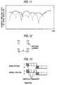
- the individual antenna elementsare susceptible to a varying fading phenomenon, the influence of the fading phenomenon on the antenna elements can be diminished by selection of the antenna elements in a manner as shown in Figure 11.
- the horizontal axisrepresents time and the vertical axis represents a receiving level of each antenna element.
- the phased-array antennais intended to form a wave beam in a predetermined direction, and hence the antenna elements must be arranged at intervals of ⁇ /2 or less. Because of such a configuration, there is a high correlation coefficient among the antenna elements, and the antenna elements are subjected to the influence of a fading phenomenon, thus deteriorating the characteristics of the phased-array antenna.
- the antenna selective diversity deviceemploys a method of transmitting a signal by selection of one antenna element from a plurality of antenna elements on the basis of the power of signals received by the antenna elements.
- the object of the present inventionis to overcome the foregoing drawbacks of the conventional array antennas and those of the conventional antenna selection diversity devices mentioned previously, as well as to provide a maximum-ratio synthetic transmission diversity device which permits an improvement in an antenna gain of an array antenna and accomplishment of a space diversity effect stemming from a reduction in the correlation among antenna elements.
- a maximum-ratio synthetic transmission diversity devicecomprises a plurality of antenna elements which are arranged intervals greater than ⁇ /2 (where ⁇ represents the wavelength of a wave to be used); a plurality of transmitters and receivers provided so as to correspond to the respective antenna elements; antenna multiplexing means for selectively connecting the antenna elements with one of the receivers and transmitters, respectively; and signal processing means which detects the phase of the signal received by each of the receivers and sends a transmission signal having a phase corresponding to the result of such detection to each of the transmitters, where the transmission signal is transmitted by way of each of the antenna elements.
- a personal handy-phone systemuses a maximum-ratio synthetic transmission diversity device as a base station, the diversity device comprising a plurality of antenna elements which are arranged intervals greater than ⁇ /2 (where ⁇ represents the wavelength of a wave to be used); a plurality of transmitters and receivers provided so as to correspond to the respective antenna elements; antenna multiplexing means for selectively connecting the antenna elements with one of the receivers and transmitters, respectively; and signal processing means which detects the phase of the signal received by each of the receivers and sends a transmission signal having a phase corresponding to the result of such detection to each of the transmitters, where the transmission signal is transmitted by way of each of the antenna elements.
- the power of the received signalmay be detected, and a transmission signal having a phase and power corresponding to the result of such detection may be sent to each of the transmitters, where the transmission signal is transmitted by way of each of the antenna elements.
- a plurality of antenna elements 20are arranged at intervals greater than ⁇ /2 in a manner such as that shown in Figure 1.
- Reference numeral 21designates an antenna multiplexer (or a switch) used for causing a transmitter 22 and a receiver 23 to selectively share the antenna element 20.
- a received signalis sent to the receiver 23, where the signal is demodulated.
- the thus-demodulated signalis sent to a phase-and-power detection section 25 provided within a digital signal processing section 24, where the power and phase of the received signal are detected.
- a control section 26calculates the phase and power of a transmission signal and sends the calculation result to a transmission signal generation circuit 27.
- the transmission signal generation circuit 27produces a transmission signal having a phase and power equivalent to those calculated by the control section.
- the transmission signalis then modulated by the transmitter 22, and the modulated signal is transmitted from each antenna element 20 via the antenna multiplexer 21.
- the deviceis characterized by the antenna gain stemming from phase synthesis which characterizes the array antenna, as well as by the space diversity gain of the antenna selection diversity device.
- the antenna elements 20are arranged in, e.g., layouts such as those shown in Figures 2A and 2B.
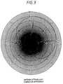
- Figure 3shows one example of an antenna radiation pattern with regard to a conventional antenna selection diversity device having four antenna elements arranged at intervals "d" of ⁇ /2 or less.
- Figure 4shows one example of an antenna radiation pattern with regard to the foregoing device according to the present invention having antenna elements arranged at intervals of ⁇ /2 or more.
- a wave radiation beam assigned directivity in a predetermined directionis not formed, but there is formed a radiation pattern having a plurality of substantially equal peaks in every direction (or through 360°). Therefore, the antenna becomes omnidirectional.
- the gain of such an antennais the same as that of an antenna having antenna elements arranged at intervals of ⁇ /2 or less.
- FIG. 5shows an embodiment of a maximum-ratio synthetic transmission diversity device according to the present invention.
- reference numerals 31a to 31ddesignate antenna elements used for both transmission and receiving purposes.
- the antenna elementsare arranged at intervals "d" greater than ⁇ /2, e.g., 5 ⁇ .
- Reference numerals 33a through 33ddesignate receivers, and 34a and 34b designate transmitters.
- the receivers and transmittersare connected to antenna elements 31a through 31d by way of antenna multiplexers (or switches) 32a through 32d, respectively.
- Reference numerals 35a through 35ddesignate analog-to-digital converters; 36a through 36d designate digital-to-analog converters; 37 designates a signal processor; and 38 designates a control section.
- a phase-and-power detection sectionis provided within each signal processor 37 for detecting a received phase and power detected for each antenna channel.
- Outputs from the receivers 33a through 33dare converted into digital signals by means of the analog-to-digital converters 35a through 35d.
- the thus-converted digital signalsare fed to the signal processor 37a.
- a digital transmission signal output from the control section 38is converted into an analog signal by means of the digital-to-analog converters 36a through 36d, and the thus-converted analog signal is delivered to the transmitters 34a through 34d.
- a signal received by the antenna element 31ais sent to the receiver 33a by way of the antenna multiplexer 32a controlled by the control section 38.
- the receiver 33ademodulates the received signal, and the analog-to-digital converter 34a converts the demodulated signal into a digital signal.
- the digital signalis sent to the signal processor section 37.
- the signal processor 37detects the relative phase and power of the signal received by each of the antenna elements 31a to 31d. On the basis of such detection, for each antenna element the signal processor section 37 calculates the relative phase and power of a transmission signal which are optimum for transmission. Data regarding the relative phase and power are sent to the control section 28.
- the control section 38produces a transmission signal on the basis of calculated data and a weighting coefficient of each antenna element and sends the thus-produced transmission signal to a digital-to-analog converter 36a, where the transmission signal is converted into an analog signal.
- the analog signalis then modulated by the transmitter 34a, and the thus-modulated signal is sent to the antenna element 31a by way of the antenna multiplexer 32a.
- the diversity devicecan achieve both the antenna gain characterizing the phased-array antenna and the space diversity characteristics.
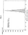
- Figures 6 and 7are graphs showing computational simulation results of the antenna gain (i.e., power gain) and an improvement in CNR (Carrier-to-Noise Ratio, i.e. a diversity gain) of a slave station with regard to a conventional space diversity system having four antenna elements 31a to 32d arranged at intervals of "d" ⁇ ⁇ /2 and with regard to the maximum-ratio synthetic transmission diversity device according to the present invention having the antenna elements arranged at intervals "d" > ⁇ /2.
- CNRCarrier-to-Noise Ratio, i.e. a diversity gain
- the antenna elementsare arranged at intervals greater than ⁇ /2 in the manner analogous to that employed in the embodiment and that a transmission signal whose phase and power are optimum for transmission is sent via each of the antenna elements, there is obtained an antenna gain of about 6 dB.
- the antenna gainis 3 dB on average. Therefore, it can be understood that the present invention enables an improvement of about 3dB in the antenna gain. Further, if an attempt is made to reduce the antenna gain to substantially the same as that of the conventional space diversity antenna, power can be saved in an amount of about 3 dB.
- improvement of CNR (a diversity gain) in a mobile station (slave station)is about 10.44 dB in average in the conventional device, while the same is about 13.62dB in average in the present invention.
- the CNRis improved about 3dB as the antenna gain.
- the maximum-ratio synthetic transmission diversity deviceis suitable for mobile communication, particularly for a PHS (personal handy-phone system) base station in which the base station communicates with a mobile station through use of the same frequency according to a TDD method.
- PHSpersonal handy-phone system
- the PHS systememploys a TDMA/TDD method (Time Division Multiple Access/Time Division Duplex) which is shown in Figure 13 and represents timing at which slots are exchanged between the base station and the mobile station.
- TDMA/TDD methodTime Division Multiple Access/Time Division Duplex
- communicationsare established between the base station and the mobile station through use of the same frequency by shifting a transmission time (or receiving time). Since the same frequency is used for both the base and mobile stations, the phase and power of a transmission signal can be readily acquired on the basis of information regarding the phase and power of the received signal. Accordingly, the present invention is suitable for the TDD method.
- a transmission diversity devicecomprises a plurality of antenna elements at intervals greater than ⁇ /2, and hence the device has both the characteristics: that is, the antenna gain stemming from phase synthesis which characterizes the array antenna, and the space diversity gain of the antenna selection diversity device.
- the present inventioncan provide a maximum-ratio synthetic transmission diversity device optimum particularly for use with a PHS base station.
Landscapes
- Engineering & Computer Science (AREA)
- Computer Networks & Wireless Communication (AREA)
- Signal Processing (AREA)
- Radio Transmission System (AREA)
- Variable-Direction Aerials And Aerial Arrays (AREA)
- Mobile Radio Communication Systems (AREA)
Abstract
Description
The present invention relates to a maximum-ratiosynthetic transmission diversity device suitable for use inmobile communications, such as communications carried out bya personal handy-phone system (PHS).
An array antenna is one type of conventional transmissionantenna and comprises phased-array antennas, adaptive-arrayantennas, or the like. Another type of conventionaltransmission antenna is an antenna selection diversityantenna. The phased-array antenna usually has aconfiguration such as that shown in Figure 8.
In the drawing,reference numeral 1 designates aplurality of antenna elements; 2 designates a phase shifter;3 designates an antenna multiplexer (or switch); 4 designatesa receiver; 5 designates a transmitter; and 6 designates acontrol section. Thephase shifter 2 has the function ofcontrolling the phase of a transmission signal and isprovided for a power feeding section of eachantenna element 1. Thecontrol section 6 controls thephase shifters 2.
The phase of a signal to be transmitted to eachantennaelement 1 is adjusted by thecontrol section 6 controllingeachphase shifter 2 so as to synthesize the phases of thetransmission signals in space, thus forming awave beam 7 ina predetermined direction and improving the gain of theantenna.
In such a case, there exists a need to arrange theantenna elements 1 at intervals of λ/2 (λ is a wavelength ofa wave to be used) or less. Taking the number ofantennaelements 1 as N, the gain of the antenna in the predetermineddirection can be improved by a factor of N.
As mentioned above, although the wave beam formed by thephased-array antenna can be adaptively controlled dependingon a change in a wave environment, the wave beam is notwidely utilized, because of its inherent problems, such asthe length of an adaptive time or the accuracy of the phaseshifter.
To eliminate these drawbacks in the conventionalphased-array antenna, an adaptive array technique has alreadybeen developed. Figure 9 shows an exemplary configuration ofa conventional adaptive array antenna. In the drawing,reference numeral 10 designates a plurality of antennaelements; 11 designates an antenna multiplexer; 12 designatesa transmitter; 13 designates a receiver; 14 designates adigital signal processing section; 15 designates aphase-and-power detection section; 16 designates atransmission signal generation circuit; and 17 designates acontrol section.
As shown in Figure 9, the adaptive array antenna alsocomprises the plurality ofantennas 10 arranged at intervals"d" equal to or less than λ/2, as in the case of thephased-array antenna. A signal received by eachantennaelement 10 is demodulated by thereceiver 13, and thecontrol section 17 calculates the phase and power of the transmissionsignal on the basis of the phase and power of the signaldetected from the demodulated signal by the phase-and-powerdetection section 15. Depending on the thus-calculated phaseand power of the transmission signal, thetransmitter 12demodulates a transmission signal generated by thetransmissionsignal generation circuit 16. Thethus-demodulated signals are fed to theantenna elements 10,so that the transmission signal is synthesized in space.This adaptive array technique solves the inherent drawbacksof the phased-array antenna, such as the length of anadaptive time or the accuracy of phase control.
In order to reduce an inter-antenna correlationcoefficient, the antenna selective diversity device comprisesa plurality of antenna elements arranged at intervals of λ/2or more and adopts a method of selecting an antenna elementto be used for transmission on the basis of the level of thepower received by the plurality of antenna elements or thelike. A relationship between the correlation coefficient andthe interval among the antenna elements assumes a curve suchas that plotted in Figure 10. In a case where the antennaelements are arranged at intervals of λ/2 or more, thecorrelation coefficient among the antenna elements can bereduced. However, in such a case, since the individualantenna elements are susceptible to a varying fadingphenomenon, the influence of the fading phenomenon on theantenna elements can be diminished by selection of the antenna elements in a manner as shown in Figure 11. InFigure 11, the horizontal axis represents time and thevertical axis represents a receiving level of each antennaelement.
The conventional transmission antennas mentionedpreviously suffer the following problems:
First, the phased-array antenna is intended to form awave beam in a predetermined direction, and hence the antennaelements must be arranged at intervals of λ/2 or less.Because of such a configuration, there is a high correlationcoefficient among the antenna elements, and the antennaelements are subjected to the influence of a fadingphenomenon, thus deteriorating the characteristics of thephased-array antenna.
The antenna selective diversity device employs a methodof transmitting a signal by selection of one antenna elementfrom a plurality of antenna elements on the basis of thepower of signals received by the antenna elements. Whencompared with the gain of the array antenna obtained throughsynthesis of phases, there is a slight improvement in thereceive power of a mobile terminal (i.e., an improvement inthe gain of the antenna). Particularly, in a fading-freeenvironment of superior visibility, there is no improvementin the receive power of the terminal.
The object of the present invention is to overcome theforegoing drawbacks of the conventional array antennas and those of the conventional antenna selection diversity devicesmentioned previously, as well as to provide a maximum-ratiosynthetic transmission diversity device which permits animprovement in an antenna gain of an array antenna andaccomplishment of a space diversity effect stemming from areduction in the correlation among antenna elements.
To accomplish the foregoing object, a maximum-ratiosynthetic transmission diversity device, according to thepresent invention, comprises a plurality of antenna elementswhich are arranged intervals greater than λ/2 (where λrepresents the wavelength of a wave to be used); a pluralityof transmitters and receivers provided so as to correspond tothe respective antenna elements; antenna multiplexing meansfor selectively connecting the antenna elements with one ofthe receivers and transmitters, respectively; and signalprocessing means which detects the phase of the signalreceived by each of the receivers and sends a transmissionsignal having a phase corresponding to the result of suchdetection to each of the transmitters, where the transmissionsignal is transmitted by way of each of the antenna elements.
A personal handy-phone system, according to the presentinvention, uses a maximum-ratio synthetic transmissiondiversity device as a base station, the diversity devicecomprising a plurality of antenna elements which are arrangedintervals greater than λ/2 (where λ represents the wavelengthof a wave to be used); a plurality of transmitters andreceivers provided so as to correspond to the respective antenna elements; antenna multiplexing means for selectivelyconnecting the antenna elements with one of the receivers andtransmitters, respectively; and signal processing means whichdetects the phase of the signal received by each of thereceivers and sends a transmission signal having a phasecorresponding to the result of such detection to each of thetransmitters, where the transmission signal is transmitted byway of each of the antenna elements.
In each of the foregoing inventions, in addition to thephase of the signal, the power of the received signal may bedetected, and a transmission signal having a phase and powercorresponding to the result of such detection may be sent toeach of the transmitters, where the transmission signal istransmitted by way of each of the antenna elements.
In an embodiment for carrying out the present invention,for example, a plurality ofantenna elements 20 are arrangedat intervals greater than λ/2 in a manner such as that shownin Figure 1.Reference numeral 21 designates an antennamultiplexer (or a switch) used for causing atransmitter 22and a receiver 23 to selectively share theantenna element 20. A received signal is sent to the receiver 23, where thesignal is demodulated. The thus-demodulated signal is sentto a phase-and-power detection section 25 provided within adigitalsignal processing section 24, where the power andphase of the received signal are detected. On the basis ofthe result of such detection, acontrol section 26 calculatesthe phase and power of a transmission signal and sends thecalculation result to a transmissionsignal generationcircuit 27. The transmissionsignal generation circuit 27produces a transmission signal having a phase and powerequivalent to those calculated by the control section. Thetransmission signal is then modulated by thetransmitter 22,and the modulated signal is transmitted from eachantennaelement 20 via theantenna multiplexer 21.
In the device according to the present invention shown inFigure 1, as a result of the antenna elements being arrangedat intervals greater than λ/2, the device is characterized bythe antenna gain stemming from phase synthesis whichcharacterizes the array antenna, as well as by the spacediversity gain of the antenna selection diversity device.
Theantenna elements 20 are arranged in, e.g., layoutssuch as those shown in Figures 2A and 2B. Figure 3 shows oneexample of an antenna radiation pattern with regard to aconventional antenna selection diversity device having fourantenna elements arranged at intervals "d" of λ/2 or less.Figure 4 shows one example of an antenna radiation patternwith regard to the foregoing device according to the presentinvention having antenna elements arranged at intervals ofλ/2 or more. As is obvious from Figure 4, in a case whereantenna elements are arranged at intervals greater than λ/2in a manner analogous to that employed by the presentinvention, a wave radiation beam assigned directivity in apredetermined direction is not formed, but there is formed aradiation pattern having a plurality of substantially equalpeaks in every direction (or through 360°). Therefore, theantenna becomes omnidirectional. Further, the gain of suchan antenna is the same as that of an antenna having antennaelements arranged at intervals of λ/2 or less.
Figure 5 shows an embodiment of a maximum-ratio synthetictransmission diversity device according to the presentinvention. In the drawing,reference numerals 31a to 31ddesignate antenna elements used for both transmission andreceiving purposes. The antenna elements are arranged atintervals "d" greater than λ/2, e.g., 5λ.
Although in the present embodiment four antenna channels"a" to "d" are provided for the diversity device, theoperation of only one channel "a" of the antenna channelswill be described. Since the other channels "b" to "d"operate in the same manner, explanations of their operationswill be omitted here.
A signal received by theantenna element 31a is sent tothereceiver 33a by way of theantenna multiplexer 32acontrolled by thecontrol section 38. Thereceiver 33ademodulates the received signal, and the analog-to-digitalconverter 34a converts the demodulated signal into a digital signal. The digital signal is sent to thesignal processorsection 37.
Thesignal processor 37 detects the relative phase andpower of the signal received by each of theantenna elements 31a to 31d. On the basis of such detection, for each antennaelement thesignal processor section 37 calculates therelative phase and power of a transmission signal which areoptimum for transmission. Data regarding the relative phaseand power are sent to the control section 28.
Thecontrol section 38 produces a transmission signal onthe basis of calculated data and a weighting coefficient ofeach antenna element and sends the thus-produced transmissionsignal to a digital-to-analog converter 36a, where thetransmission signal is converted into an analog signal. Theanalog signal is then modulated by thetransmitter 34a, andthe thus-modulated signal is sent to theantenna element 31aby way of theantenna multiplexer 32a.
Through execution of the foregoing operations for eachantenna element, the diversity device can achieve both theantenna gain characterizing the phased-array antenna and thespace diversity characteristics.
Figures 6 and 7 are graphs showing computationalsimulation results of the antenna gain (i.e., power gain) andan improvement in CNR (Carrier-to-Noise Ratio, i.e. adiversity gain) of a slave station with regard to aconventional space diversity system having fourantennaelements 31a to 32d arranged at intervals of "d" < λ/2 and with regard to the maximum-ratio synthetic transmissiondiversity device according to the present invention havingthe antenna elements arranged at intervals "d" > λ/2.
As is obvious from Figure 7, provided that the antennaelements are arranged at intervals greater than λ/2 in themanner analogous to that employed in the embodiment and thata transmission signal whose phase and power are optimum fortransmission is sent via each of the antenna elements, thereis obtained an antenna gain of about 6 dB. In contrast, inthe case of the conventional space diversity system shown inFigure 6, the antenna gain is 3 dB on average. Therefore, itcan be understood that the present invention enables animprovement of about 3dB in the antenna gain. Further, if anattempt is made to reduce the antenna gain to substantiallythe same as that of the conventional space diversity antenna,power can be saved in an amount of about 3 dB.
As apparent form Figures 6 and 7, improvement of CNR (adiversity gain) in a mobile station (slave station) is about10.44 dB in average in the conventional device, while thesame is about 13.62dB in average in the present invention.According to the invention, the CNR is improved about 3dB asthe antenna gain.
The maximum-ratio synthetic transmission diversity deviceaccording to the present invention is suitable for mobilecommunication, particularly for a PHS (personal handy-phonesystem) base station in which the base station communicates with a mobile station through use of the same frequencyaccording to a TDD method.
The PHS system employs a TDMA/TDD method (Time DivisionMultiple Access/Time Division Duplex) which is shown inFigure 13 and represents timing at which slots are exchangedbetween the base station and the mobile station. In short,communications are established between the base station andthe mobile station through use of the same frequency byshifting a transmission time (or receiving time). Since thesame frequency is used for both the base and mobile stations,the phase and power of a transmission signal can be readilyacquired on the basis of information regarding the phase andpower of the received signal. Accordingly, the presentinvention is suitable for the TDD method.
As has been described above, according to the presentinvention, a transmission diversity device comprises aplurality of antenna elements at intervals greater than λ/2,and hence the device has both the characteristics: that is,the antenna gain stemming from phase synthesis whichcharacterizes the array antenna, and the space diversity gainof the antenna selection diversity device. Particularly, thepresent invention can provide a maximum-ratio synthetictransmission diversity device optimum particularly for usewith a PHS base station.
Claims (4)
- A maximum-ratio synthetic transmission diversity devicecomprising:a plurality of antenna elements (20, 31a-31d) whichare arranged intervals greater than λ/2 (where λrepresents the wavelength of a wave to be used);a plurality of transmitters (22,34a-34d) andreceivers (33a-33d) provided so as to correspond to therespective antenna elements (31a-31d);antenna multiplexing means (21,32a-d) forselectively connecting the elements (20,31a-31d) withone of the receivers (33a-33d) and transmitters (22,34a-34d),respectively; andsignal processing means (24,37) which detects thephase of the signal (25a) received by each of thereceivers (33a-33d) and sends a transmission signal (27)having a phase corresponding to the result of suchdetection to each of the transmitters (22,34a-34d),where the transmission signal is transmitted by way ofeach of the antenna elements (31a-31d).
- The maximum-ratio synthetic transmission diversitydevice as claimed in claim 1, wherein the signalprocessing means (24,37) detects the power of the signalreceived by each of the receivers in addition to thephase of the signal (25) and sends a transmission signal(27) having a phase and power corresponding to theresult of such detection to each of the transmitters(22,34a-34d), where the transmission signal istransmitted by way of each of the antenna elements(20,34a-34d).
- A personal handy-phone system which uses a maximum-ratiosynthetic transmission diversity device as a basestation, the diversity device comprising;a plurality of antenna elements (20) which arearranged intervals greater than λ/2 (where λ representsthe wavelength of a wave to be used);a plurality of transmitters (34a-34d) and receivers(33a-33d) provided so as to correspond to the respectiveantenna elements (31a-31d);
antenna multiplexing means (21,32a-d) for selectivelyconnecting the antenna elements (31a-31d) with one ofthe receivers (33a-33d) and transmitters (34a-34d),respectively; andsignal processing means (24,37) which detects thephase of the signal (25) received by each of thereceivers (33a-33d) and sends a transmission signal (27)having a phase corresponding to the result of suchdetection to each of the transmitters, (34a-34d), wherethe transmission signal is transmitted by way of each ofthe antenna elements (31a-31d). - The personal handy-phone system as claimed in claim 3,wherein the signal processing means (24,37) detects thepower of the signal (25) received by each of thereceivers (33a-33d) in addition to the phase of thesignal and sends a transmission signal (27) having aphase and power corresponding to the result of suchdetection (25) to each of the transmitters (34a-34d),where the transmission signal is transmitted by way ofeach of the antenna elements (31a-31d).
Applications Claiming Priority (3)
| Application Number | Priority Date | Filing Date | Title |
|---|---|---|---|
| JP15803897 | 1997-05-30 | ||
| JP9158038AJPH10336087A (en) | 1997-05-30 | 1997-05-30 | Maximum ratio combining transmit diversity device |
| JP158038/97 | 1997-05-30 |
Publications (2)
| Publication Number | Publication Date |
|---|---|
| EP0881782A2true EP0881782A2 (en) | 1998-12-02 |
| EP0881782A3 EP0881782A3 (en) | 2002-10-02 |
Family
ID=15662930
Family Applications (1)
| Application Number | Title | Priority Date | Filing Date |
|---|---|---|---|
| EP98109882AWithdrawnEP0881782A3 (en) | 1997-05-30 | 1998-05-29 | Maximum-ratio synthetic transmission diversity device |
Country Status (4)
| Country | Link |
|---|---|
| US (1) | US6453150B1 (en) |
| EP (1) | EP0881782A3 (en) |
| JP (1) | JPH10336087A (en) |
| CN (1) | CN1098573C (en) |
Cited By (8)
| Publication number | Priority date | Publication date | Assignee | Title |
|---|---|---|---|---|
| WO2000077951A1 (en)* | 1999-06-11 | 2000-12-21 | Allgon Ab | A method for controlling the radiation pattern of an antenna means, an antenna system and a radio communication device |
| EP1148659A1 (en)* | 2000-04-18 | 2001-10-24 | Sony International (Europe) GmbH | OFDM diversity transmission |
| EP1182817A1 (en)* | 2000-08-24 | 2002-02-27 | Sony International (Europe) GmbH | Communication device for receiving and transmitting OFDM signals in a wireless communication system |
| US6807145B1 (en)* | 1999-12-06 | 2004-10-19 | Lucent Technologies Inc. | Diversity in orthogonal frequency division multiplexing systems |
| US7149258B2 (en) | 2001-11-28 | 2006-12-12 | Telefonaktiebolaget L M Ericsson (Publ) | Method and apparatus for estimation of phase offset between communication channels |
| EP2256981A2 (en) | 2000-08-24 | 2010-12-01 | Sony Deutschland Gmbh | Communication device for receiving and transmitting OFDM signals in a wireless communication system |
| US8457250B2 (en) | 2000-11-20 | 2013-06-04 | Sony Deutschland Gmbh | OFDM pre-equalizing |
| US9106286B2 (en) | 2000-06-13 | 2015-08-11 | Comcast Cable Communications, Llc | Network communication using diversity |
Families Citing this family (12)
| Publication number | Priority date | Publication date | Assignee | Title |
|---|---|---|---|---|
| AU5567300A (en) | 1999-06-23 | 2001-01-09 | Japan As Represented By President Of Hokkaido University | Radio device |
| AU2002348700A1 (en)* | 2002-01-11 | 2003-07-24 | Agere Systems (Ireland) Research Limited | Timing control in data receivers and transmitters |
| US20050232178A1 (en)* | 2004-03-18 | 2005-10-20 | Eagle Broadband, Inc. | Satellite repeater having multi-handset capability |
| US7414579B2 (en)* | 2004-09-23 | 2008-08-19 | Interdigital Technology Corporation | Blind signal separation using correlated antenna elements |
| CN100359822C (en)* | 2004-10-14 | 2008-01-02 | 中兴通讯股份有限公司 | Method and device for treating emission diversity selected by antenna |
| JP4563328B2 (en)* | 2006-03-07 | 2010-10-13 | 日本電信電話株式会社 | Wireless communication device |
| CN100466774C (en)* | 2007-05-18 | 2009-03-04 | 华为技术有限公司 | A sectorized base station |
| US8180404B2 (en)* | 2008-12-11 | 2012-05-15 | At&T Mobility Ii Llc. | Sharing antennas for increased multiple-input uplink reception |
| US8737529B2 (en) | 2010-01-18 | 2014-05-27 | Broadcom Corporation | Multiple antenna signal transmission |
| US8432997B2 (en) | 2010-01-18 | 2013-04-30 | Broadcom Corporation | Method and system of beamforming a broadband signal through a multiport network |
| CN102834731A (en)* | 2010-02-08 | 2012-12-19 | 美国博通公司 | Method and system of beamforming a broadband signal through a multiport network |
| EP2485327A3 (en)* | 2011-02-08 | 2014-01-01 | Broadcom Corporation | Method and system of beamforming a broadband signal through a multiport network |
Family Cites Families (21)
| Publication number | Priority date | Publication date | Assignee | Title |
|---|---|---|---|---|
| US4166274A (en)* | 1978-06-02 | 1979-08-28 | Bell Telephone Laboratories, Incorporated | Techniques for cophasing elements of a phased antenna array |
| US4217587A (en)* | 1978-08-14 | 1980-08-12 | Westinghouse Electric Corp. | Antenna beam steering controller |
| US4314250A (en)* | 1979-08-03 | 1982-02-02 | Communications Satellite Corporation | Intermodulation product suppression by antenna processing |
| CA1212746A (en)* | 1983-01-31 | 1986-10-14 | R. Ian Macdonald | Optoelectronically switched phase shifter for radar and satellite phased array antennas |
| JP2552928B2 (en)* | 1990-01-31 | 1996-11-13 | 三菱電機株式会社 | Antenna selection diversity receiver |
| DE4101629C3 (en)* | 1991-01-21 | 2003-06-26 | Fuba Automotive Gmbh | Antenna diversity system with at least two antennas for the mobile reception of meter and decimeter waves |
| US5515378A (en)* | 1991-12-12 | 1996-05-07 | Arraycomm, Inc. | Spatial division multiple access wireless communication systems |
| SE9200283D0 (en)* | 1992-02-03 | 1992-02-03 | Peter Aahl | DYNAMIC VARIABLE RADIO STATION DVR |
| JPH05268128A (en)* | 1992-03-18 | 1993-10-15 | Kokusai Denshin Denwa Co Ltd <Kdd> | Cdma communication system |
| SE470078B (en)* | 1992-03-27 | 1993-11-01 | Ericsson Telefon Ab L M | Base station for cellular frequency hopping TDMA radio communication systems |
| US5283587A (en)* | 1992-11-30 | 1994-02-01 | Space Systems/Loral | Active transmit phased array antenna |
| FI932605A7 (en)* | 1993-06-07 | 1994-12-08 | Nokia Telecommunications Oy | Base station receiver equipment |
| US5619503A (en)* | 1994-01-11 | 1997-04-08 | Ericsson Inc. | Cellular/satellite communications system with improved frequency re-use |
| US5621770A (en)* | 1994-08-31 | 1997-04-15 | Motorola, Inc. | Method and system for processing first and second digital signal versions of a signal in a diversity receiver |
| GB9514659D0 (en)* | 1995-07-18 | 1995-09-13 | Northern Telecom Ltd | An antenna downlink beamsteering arrangement |
| JP3441256B2 (en)* | 1995-09-06 | 2003-08-25 | 株式会社東芝 | Wireless communication system |
| US5815116A (en)* | 1995-11-29 | 1998-09-29 | Trw Inc. | Personal beam cellular communication system |
| US6122260A (en)* | 1996-12-16 | 2000-09-19 | Civil Telecommunications, Inc. | Smart antenna CDMA wireless communication system |
| SE508113C2 (en)* | 1996-12-30 | 1998-08-31 | Ericsson Telefon Ab L M | Transmitter interference removal |
| US5909641A (en)* | 1997-02-24 | 1999-06-01 | At&T Wireless Services Inc. | Transmit/receive switch |
| US5977910A (en)* | 1997-08-07 | 1999-11-02 | Space Systems/Loral, Inc. | Multibeam phased array antenna system |
- 1997
- 1997-05-30JPJP9158038Apatent/JPH10336087A/enactivePending
- 1998
- 1998-05-27USUS09/085,489patent/US6453150B1/ennot_activeExpired - Fee Related
- 1998-05-29EPEP98109882Apatent/EP0881782A3/ennot_activeWithdrawn
- 1998-06-01CNCN98102045Apatent/CN1098573C/ennot_activeExpired - Fee Related
Non-Patent Citations (3)
| Title |
|---|
| BORNKAMP B.; KEGEL A.; PRASAD R.: "Macro and micro diversity in land-mobile cellular radio telephony networks with discontinuous voice transmission", IEEE, 6 November 1995 (1995-11-06), 1995 FOURTH IEEE INTERNATIONAL CONFERENCE ON UNIVERSAL PERSONAL COMMUNICATIONS RECORD. GATEWAY TO THE 21ST. CENTURY. TOKYO, pages 590 - 594, XP000690020, DOI: doi:10.1109/ICUPC.1995.497077* |
| LEE W.C.Y.: "Study of the antenna array configuration of an M- branch diversity combining mobile radio receiver", IEEE TRANS VEH TECHNOL, 30 November 1971 (1971-11-30), USA, pages 93 - 104, XP011486556, DOI: doi:10.1109/T-VT.1971.23486* |
| WINTERS J.H.; SALZ J.; GITLIN R.D.: "The capacity of wireless communication systems can be substantially increased by the use of antenna diversity", IEEE CONFERENCE PROCEEDINGS, 29 September 1992 (1992-09-29), NEW YORK, NY, USA, pages 28 - 32, XP010061011* |
Cited By (46)
| Publication number | Priority date | Publication date | Assignee | Title |
|---|---|---|---|---|
| WO2000077951A1 (en)* | 1999-06-11 | 2000-12-21 | Allgon Ab | A method for controlling the radiation pattern of an antenna means, an antenna system and a radio communication device |
| RU2253170C2 (en)* | 1999-06-11 | 2005-05-27 | Амс Сентьюриен Аб | Method for controlling directivity pattern of antenna facilities, set of antennas, and radio communication device |
| US6807145B1 (en)* | 1999-12-06 | 2004-10-19 | Lucent Technologies Inc. | Diversity in orthogonal frequency division multiplexing systems |
| US7414962B2 (en) | 2000-04-18 | 2008-08-19 | Sony Deutschland Gmbh | OFDM diversity transmission |
| EP1148659A1 (en)* | 2000-04-18 | 2001-10-24 | Sony International (Europe) GmbH | OFDM diversity transmission |
| USRE45269E1 (en) | 2000-04-18 | 2014-12-02 | Sony Deutschland Gmbh | OFDM diversity transmission |
| US9515788B2 (en) | 2000-06-13 | 2016-12-06 | Comcast Cable Communications, Llc | Originator and recipient based transmissions in wireless communications |
| US9391745B2 (en) | 2000-06-13 | 2016-07-12 | Comcast Cable Communications, Llc | Multi-user transmissions |
| US9820209B1 (en) | 2000-06-13 | 2017-11-14 | Comcast Cable Communications, Llc | Data routing for OFDM transmissions |
| US9654323B2 (en) | 2000-06-13 | 2017-05-16 | Comcast Cable Communications, Llc | Data routing for OFDM transmission based on observed node capacities |
| US10257765B2 (en) | 2000-06-13 | 2019-04-09 | Comcast Cable Communications, Llc | Transmission of OFDM symbols |
| US10349332B2 (en) | 2000-06-13 | 2019-07-09 | Comcast Cable Communications, Llc | Network communication using selected resources |
| US9401783B1 (en) | 2000-06-13 | 2016-07-26 | Comcast Cable Communications, Llc | Transmission of data to multiple nodes |
| US9722842B2 (en) | 2000-06-13 | 2017-08-01 | Comcast Cable Communications, Llc | Transmission of data using a plurality of radio frequency channels |
| US9356666B1 (en) | 2000-06-13 | 2016-05-31 | Comcast Cable Communications, Llc | Originator and recipient based transmissions in wireless communications |
| US9344233B2 (en) | 2000-06-13 | 2016-05-17 | Comcast Cable Communications, Llc | Originator and recipient based transmissions in wireless communications |
| US9209871B2 (en) | 2000-06-13 | 2015-12-08 | Comcast Cable Communications, Llc | Network communication using diversity |
| US9197297B2 (en) | 2000-06-13 | 2015-11-24 | Comcast Cable Communications, Llc | Network communication using diversity |
| USRE45807E1 (en) | 2000-06-13 | 2015-11-17 | Comcast Cable Communications, Llc | Apparatus for transmitting a signal including transmit data to a multiple-input capable node |
| USRE45775E1 (en) | 2000-06-13 | 2015-10-20 | Comcast Cable Communications, Llc | Method and system for robust, secure, and high-efficiency voice and packet transmission over ad-hoc, mesh, and MIMO communication networks |
| US9106286B2 (en) | 2000-06-13 | 2015-08-11 | Comcast Cable Communications, Llc | Network communication using diversity |
| US7633848B2 (en) | 2000-08-24 | 2009-12-15 | Sony Deutschland Gmbh | Communication device for receiving and transmitting OFDM signals in a wireless communication system |
| EP2256979A2 (en) | 2000-08-24 | 2010-12-01 | Sony Deutschland Gmbh | Communication device for receiving and transmitting OFDM signals in a wireless communication system |
| US8743675B2 (en) | 2000-08-24 | 2014-06-03 | Sony Deutschland Gmbh | Communication device for receiving and transmitting OFDM signals in a wireless communication system |
| EP1182817A1 (en)* | 2000-08-24 | 2002-02-27 | Sony International (Europe) GmbH | Communication device for receiving and transmitting OFDM signals in a wireless communication system |
| US7085223B2 (en) | 2000-08-24 | 2006-08-01 | Sony International (Europe) Gmbh | Communication device for receiving and transmitting OFDM signals in a wireless communication system |
| US9954710B2 (en) | 2000-08-24 | 2018-04-24 | Sony Deutschland Gmbh | Communication device for receiving and transmitting OFDM signals in a wireless communication system |
| US7961588B2 (en) | 2000-08-24 | 2011-06-14 | Sony Deutschland Gmbh | Communication device for receiving and transmitting OFDM signals in a wireless communication system |
| US7957258B2 (en) | 2000-08-24 | 2011-06-07 | Sony Deutschland Gmbh | Communication device for receiving and transmitting OFDM signals in a wireless communication system |
| EP2256979A3 (en)* | 2000-08-24 | 2011-03-02 | Sony Deutschland Gmbh | Communication device for transmitting OFDM signals in a wireless communication system |
| EP2256980A3 (en)* | 2000-08-24 | 2011-03-02 | Sony Deutschland Gmbh | Communication device for transmitting OFDM signals in a wireless communication system |
| EP2256981A3 (en)* | 2000-08-24 | 2011-03-02 | Sony Deutschland Gmbh | Communication device for receiving OFDM signals in a wireless communication system |
| EP2256980A2 (en) | 2000-08-24 | 2010-12-01 | Sony Deutschland Gmbh | Communication device for receiving and transmitting OFDM signals in a wireless communication system |
| EP2256981A2 (en) | 2000-08-24 | 2010-12-01 | Sony Deutschland Gmbh | Communication device for receiving and transmitting OFDM signals in a wireless communication system |
| EP2755344A2 (en) | 2000-08-24 | 2014-07-16 | Sony Deutschland Gmbh | Communication device for transmitting OFDM signals in a wireless communication system |
| EP1821480A1 (en)* | 2000-08-24 | 2007-08-22 | Sony Deutschland Gmbh | Communication device for receiving and transmitting OFDM signals in a wireless communication system |
| US9455806B2 (en) | 2000-08-24 | 2016-09-27 | Sony Deutschland Gmbh | Communication device for receiving and transmitting OFDM signals in a wireless communication system |
| EP2031788A1 (en) | 2000-08-24 | 2009-03-04 | Sony Deutschland Gmbh | Communication device for receiving and transmitting OFDM signals in a wireless communication system |
| US9596059B2 (en) | 2000-08-24 | 2017-03-14 | Sony Deutschland Gmbh | Communication device for receiving and transmitting OFDM signals in a wireless communication system |
| US7414959B2 (en) | 2000-08-24 | 2008-08-19 | Sony Deutschland Gmbh | Communication device for receiving and transmitting OFDM signals in a wireless communication system |
| US9450792B2 (en) | 2000-11-20 | 2016-09-20 | Sony Deutschland Gmbh | OFDM pre-equalizing |
| US8457250B2 (en) | 2000-11-20 | 2013-06-04 | Sony Deutschland Gmbh | OFDM pre-equalizing |
| US9967118B2 (en) | 2000-11-20 | 2018-05-08 | Sony Deutschland Gmbh | OFDM pre-equalizing |
| US9008224B2 (en) | 2000-11-20 | 2015-04-14 | Sony Deutschland Gmbh | OFDM pre-equalizing |
| US8948302B2 (en) | 2000-11-20 | 2015-02-03 | Sony Deutschland Gmbh | OFDM pre-equalizing |
| US7149258B2 (en) | 2001-11-28 | 2006-12-12 | Telefonaktiebolaget L M Ericsson (Publ) | Method and apparatus for estimation of phase offset between communication channels |
Also Published As
| Publication number | Publication date |
|---|---|
| CN1201306A (en) | 1998-12-09 |
| CN1098573C (en) | 2003-01-08 |
| JPH10336087A (en) | 1998-12-18 |
| EP0881782A3 (en) | 2002-10-02 |
| US6453150B1 (en) | 2002-09-17 |
Similar Documents
| Publication | Publication Date | Title |
|---|---|---|
| US6453150B1 (en) | Maximum-ratio synthetic transmission diversity device | |
| EP0713262B1 (en) | Antenna apparatus and direction method | |
| US6308085B1 (en) | Distributed antenna system and method of controlling the same | |
| US6314305B1 (en) | Transmitter/receiver for combined adaptive array processing and fixed beam switching | |
| KR100883943B1 (en) | Wireless communication using adaptive antenna array | |
| RU2155460C2 (en) | Antenna with wide lobe of directivity pattern | |
| KR100483901B1 (en) | Antenna assembly and related methods for wireless communication devices | |
| US6577879B1 (en) | System and method for simultaneous transmission of signals in multiple beams without feeder cable coherency | |
| EP1202389B1 (en) | Transmission antenna directivity control apparatus and method | |
| EP2175572B1 (en) | Transmitting and receiving apparatus and method | |
| US5884192A (en) | Diversity combining for antennas | |
| EP2456279A1 (en) | Antenna system | |
| EP0804858A1 (en) | Spectrally efficient high capacity wireless communication systems | |
| EP1298825B1 (en) | Apparatus and method using smart antenna in fdd wireless communication system | |
| US6526291B1 (en) | Method and a system for radio transmission | |
| US6611511B1 (en) | Cellular telephone communication system using sector splitting for improved performance | |
| US6822619B2 (en) | Antenna system | |
| EP0776550B1 (en) | A receiver with an antenna array | |
| US6218988B1 (en) | Array antenna transmitter with a high transmission gain proportional to the number of antenna elements | |
| US6002947A (en) | Antenna array configuration | |
| CA2215788A1 (en) | Fixed station of mobile radio system | |
| AU4115599A (en) | Mobile communication system and method for establishing synchronization in mobile communications | |
| KR19990053963A (en) | Smart Antenna and Radiation Pattern Generation Method for Automatic Base Station Auto Discovery | |
| JP2000286769A (en) | Receiver | |
| WO2003038949A1 (en) | Adaptive radio antennas |
Legal Events
| Date | Code | Title | Description |
|---|---|---|---|
| PUAI | Public reference made under article 153(3) epc to a published international application that has entered the european phase | Free format text:ORIGINAL CODE: 0009012 | |
| AK | Designated contracting states | Kind code of ref document:A2 Designated state(s):AT BE CH CY DE DK ES FI FR GB GR IE IT LI LU MC NL PT SE | |
| AX | Request for extension of the european patent | Free format text:AL;LT;LV;MK;RO;SI | |
| PUAL | Search report despatched | Free format text:ORIGINAL CODE: 0009013 | |
| AK | Designated contracting states | Kind code of ref document:A3 Designated state(s):AT BE CH CY DE DK ES FI FR GB GR IE IT LI LU MC NL PT SE | |
| AX | Request for extension of the european patent | Free format text:AL;LT;LV;MK;RO;SI | |
| 17P | Request for examination filed | Effective date:20030108 | |
| AKX | Designation fees paid | Designated state(s):DE FR GB | |
| STAA | Information on the status of an ep patent application or granted ep patent | Free format text:STATUS: THE APPLICATION HAS BEEN WITHDRAWN | |
| 18W | Application withdrawn | Effective date:20070829 |