EP0880948B1 - Stent and stent-graft for treating branched vessels - Google Patents
Stent and stent-graft for treating branched vesselsDownload PDFInfo
- Publication number
- EP0880948B1 EP0880948B1EP98303442AEP98303442AEP0880948B1EP 0880948 B1EP0880948 B1EP 0880948B1EP 98303442 AEP98303442 AEP 98303442AEP 98303442 AEP98303442 AEP 98303442AEP 0880948 B1EP0880948 B1EP 0880948B1
- Authority
- EP
- European Patent Office
- Prior art keywords
- section
- stent
- diseased
- filaments
- graft
- Prior art date
- Legal status (The legal status is an assumption and is not a legal conclusion. Google has not performed a legal analysis and makes no representation as to the accuracy of the status listed.)
- Expired - Lifetime
Links
- 239000012528membraneSubstances0.000claims5
- 230000003319supportive effectEffects0.000claims2
- 210000000709aortaAnatomy0.000description87
- 210000002254renal arteryAnatomy0.000description42
- 238000004873anchoringMethods0.000description15
- 238000011144upstream manufacturingMethods0.000description15
- 210000001715carotid arteryAnatomy0.000description10
- 230000017531blood circulationEffects0.000description9
- 206010002329AneurysmDiseases0.000description8
- 210000001168carotid artery commonAnatomy0.000description8
- 239000000463materialSubstances0.000description8
- 210000000269carotid artery externalAnatomy0.000description7
- 210000003090iliac arteryAnatomy0.000description7
- 210000004004carotid artery internalAnatomy0.000description6
- 230000001965increasing effectEffects0.000description6
- 229910045601alloyInorganic materials0.000description5
- 239000000956alloySubstances0.000description5
- 230000006870functionEffects0.000description5
- 238000000034methodMethods0.000description5
- 230000036262stenosisEffects0.000description5
- 208000031481Pathologic ConstrictionDiseases0.000description4
- 208000002223abdominal aortic aneurysmDiseases0.000description4
- 238000004519manufacturing processMethods0.000description4
- 208000037804stenosisDiseases0.000description4
- 208000007474aortic aneurysmDiseases0.000description3
- 239000008280bloodSubstances0.000description3
- 210000004369bloodAnatomy0.000description3
- 230000008859changeEffects0.000description3
- 238000002513implantationMethods0.000description3
- 230000007246mechanismEffects0.000description3
- 210000000702aorta abdominalAnatomy0.000description2
- 210000001367arteryAnatomy0.000description2
- 229910000701elgiloys (Co-Cr-Ni Alloy)Inorganic materials0.000description2
- 238000005516engineering processMethods0.000description2
- 210000001105femoral arteryAnatomy0.000description2
- 239000005020polyethylene terephthalateSubstances0.000description2
- 229910000619316 stainless steelInorganic materials0.000description1
- 229920004934Dacron®Polymers0.000description1
- 208000031940Disease AttributesDiseases0.000description1
- 239000004705High-molecular-weight polyethyleneSubstances0.000description1
- 241001465754MetazoaSpecies0.000description1
- 239000004698PolyethyleneSubstances0.000description1
- 229910000831SteelInorganic materials0.000description1
- 230000001154acute effectEffects0.000description1
- 239000000853adhesiveSubstances0.000description1
- 230000001070adhesive effectEffects0.000description1
- 210000003484anatomyAnatomy0.000description1
- 206010002906aortic stenosisDiseases0.000description1
- 239000000560biocompatible materialSubstances0.000description1
- 210000002302brachial arteryAnatomy0.000description1
- 238000009954braidingMethods0.000description1
- 230000015271coagulationEffects0.000description1
- 238000005345coagulationMethods0.000description1
- 239000011248coating agentSubstances0.000description1
- 238000000576coating methodMethods0.000description1
- 239000002131composite materialSubstances0.000description1
- 230000006835compressionEffects0.000description1
- 238000007906compressionMethods0.000description1
- 238000010276constructionMethods0.000description1
- 238000007796conventional methodMethods0.000description1
- 238000005520cutting processMethods0.000description1
- 230000003247decreasing effectEffects0.000description1
- 230000007850degenerationEffects0.000description1
- 201000010099diseaseDiseases0.000description1
- 208000037265diseases, disorders, signs and symptomsDiseases0.000description1
- 230000002708enhancing effectEffects0.000description1
- 229920000295expanded polytetrafluoroethylenePolymers0.000description1
- 239000000835fiberSubstances0.000description1
- 239000012530fluidSubstances0.000description1
- 230000036541healthEffects0.000description1
- 239000002184metalSubstances0.000description1
- 230000017074necrotic cell deathEffects0.000description1
- 229910001000nickel titaniumInorganic materials0.000description1
- HLXZNVUGXRDIFK-UHFFFAOYSA-Nnickel titaniumChemical compound[Ti].[Ti].[Ti].[Ti].[Ti].[Ti].[Ti].[Ti].[Ti].[Ti].[Ti].[Ni].[Ni].[Ni].[Ni].[Ni].[Ni].[Ni].[Ni].[Ni].[Ni].[Ni].[Ni].[Ni].[Ni]HLXZNVUGXRDIFK-UHFFFAOYSA-N0.000description1
- 235000015097nutrientsNutrition0.000description1
- 229920000728polyesterPolymers0.000description1
- -1polyethylenePolymers0.000description1
- 229920000573polyethylenePolymers0.000description1
- 229920000139polyethylene terephthalatePolymers0.000description1
- 229920000642polymerPolymers0.000description1
- 210000002321radial arteryAnatomy0.000description1
- 230000003014reinforcing effectEffects0.000description1
- 238000009877renderingMethods0.000description1
- 230000008439repair processEffects0.000description1
- 238000007789sealingMethods0.000description1
- 238000001228spectrumMethods0.000description1
- 238000009987spinningMethods0.000description1
- 239000010959steelSubstances0.000description1
- 239000013589supplementSubstances0.000description1
- 230000001502supplementing effectEffects0.000description1
- 238000001356surgical procedureMethods0.000description1
- 239000004753textileSubstances0.000description1
- 238000003466weldingMethods0.000description1
- 238000004804windingMethods0.000description1
Images


Classifications
- A—HUMAN NECESSITIES
- A61—MEDICAL OR VETERINARY SCIENCE; HYGIENE
- A61F—FILTERS IMPLANTABLE INTO BLOOD VESSELS; PROSTHESES; DEVICES PROVIDING PATENCY TO, OR PREVENTING COLLAPSING OF, TUBULAR STRUCTURES OF THE BODY, e.g. STENTS; ORTHOPAEDIC, NURSING OR CONTRACEPTIVE DEVICES; FOMENTATION; TREATMENT OR PROTECTION OF EYES OR EARS; BANDAGES, DRESSINGS OR ABSORBENT PADS; FIRST-AID KITS
- A61F2/00—Filters implantable into blood vessels; Prostheses, i.e. artificial substitutes or replacements for parts of the body; Appliances for connecting them with the body; Devices providing patency to, or preventing collapsing of, tubular structures of the body, e.g. stents
- A61F2/82—Devices providing patency to, or preventing collapsing of, tubular structures of the body, e.g. stents
- A61F2/86—Stents in a form characterised by the wire-like elements; Stents in the form characterised by a net-like or mesh-like structure
- A61F2/90—Stents in a form characterised by the wire-like elements; Stents in the form characterised by a net-like or mesh-like structure characterised by a net-like or mesh-like structure
- A—HUMAN NECESSITIES
- A61—MEDICAL OR VETERINARY SCIENCE; HYGIENE
- A61F—FILTERS IMPLANTABLE INTO BLOOD VESSELS; PROSTHESES; DEVICES PROVIDING PATENCY TO, OR PREVENTING COLLAPSING OF, TUBULAR STRUCTURES OF THE BODY, e.g. STENTS; ORTHOPAEDIC, NURSING OR CONTRACEPTIVE DEVICES; FOMENTATION; TREATMENT OR PROTECTION OF EYES OR EARS; BANDAGES, DRESSINGS OR ABSORBENT PADS; FIRST-AID KITS
- A61F2/00—Filters implantable into blood vessels; Prostheses, i.e. artificial substitutes or replacements for parts of the body; Appliances for connecting them with the body; Devices providing patency to, or preventing collapsing of, tubular structures of the body, e.g. stents
- A61F2/02—Prostheses implantable into the body
- A61F2/04—Hollow or tubular parts of organs, e.g. bladders, tracheae, bronchi or bile ducts
- A61F2/06—Blood vessels
- A61F2/07—Stent-grafts
- A—HUMAN NECESSITIES
- A61—MEDICAL OR VETERINARY SCIENCE; HYGIENE
- A61F—FILTERS IMPLANTABLE INTO BLOOD VESSELS; PROSTHESES; DEVICES PROVIDING PATENCY TO, OR PREVENTING COLLAPSING OF, TUBULAR STRUCTURES OF THE BODY, e.g. STENTS; ORTHOPAEDIC, NURSING OR CONTRACEPTIVE DEVICES; FOMENTATION; TREATMENT OR PROTECTION OF EYES OR EARS; BANDAGES, DRESSINGS OR ABSORBENT PADS; FIRST-AID KITS
- A61F2/00—Filters implantable into blood vessels; Prostheses, i.e. artificial substitutes or replacements for parts of the body; Appliances for connecting them with the body; Devices providing patency to, or preventing collapsing of, tubular structures of the body, e.g. stents
- A61F2/82—Devices providing patency to, or preventing collapsing of, tubular structures of the body, e.g. stents
- A61F2/856—Single tubular stent with a side portal passage
- A—HUMAN NECESSITIES
- A61—MEDICAL OR VETERINARY SCIENCE; HYGIENE
- A61F—FILTERS IMPLANTABLE INTO BLOOD VESSELS; PROSTHESES; DEVICES PROVIDING PATENCY TO, OR PREVENTING COLLAPSING OF, TUBULAR STRUCTURES OF THE BODY, e.g. STENTS; ORTHOPAEDIC, NURSING OR CONTRACEPTIVE DEVICES; FOMENTATION; TREATMENT OR PROTECTION OF EYES OR EARS; BANDAGES, DRESSINGS OR ABSORBENT PADS; FIRST-AID KITS
- A61F2/00—Filters implantable into blood vessels; Prostheses, i.e. artificial substitutes or replacements for parts of the body; Appliances for connecting them with the body; Devices providing patency to, or preventing collapsing of, tubular structures of the body, e.g. stents
- A61F2/02—Prostheses implantable into the body
- A61F2/04—Hollow or tubular parts of organs, e.g. bladders, tracheae, bronchi or bile ducts
- A61F2/06—Blood vessels
- A61F2002/061—Blood vessels provided with means for allowing access to secondary lumens
- A—HUMAN NECESSITIES
- A61—MEDICAL OR VETERINARY SCIENCE; HYGIENE
- A61F—FILTERS IMPLANTABLE INTO BLOOD VESSELS; PROSTHESES; DEVICES PROVIDING PATENCY TO, OR PREVENTING COLLAPSING OF, TUBULAR STRUCTURES OF THE BODY, e.g. STENTS; ORTHOPAEDIC, NURSING OR CONTRACEPTIVE DEVICES; FOMENTATION; TREATMENT OR PROTECTION OF EYES OR EARS; BANDAGES, DRESSINGS OR ABSORBENT PADS; FIRST-AID KITS
- A61F2/00—Filters implantable into blood vessels; Prostheses, i.e. artificial substitutes or replacements for parts of the body; Appliances for connecting them with the body; Devices providing patency to, or preventing collapsing of, tubular structures of the body, e.g. stents
- A61F2/02—Prostheses implantable into the body
- A61F2/04—Hollow or tubular parts of organs, e.g. bladders, tracheae, bronchi or bile ducts
- A61F2/06—Blood vessels
- A61F2002/065—Y-shaped blood vessels
- A—HUMAN NECESSITIES
- A61—MEDICAL OR VETERINARY SCIENCE; HYGIENE
- A61F—FILTERS IMPLANTABLE INTO BLOOD VESSELS; PROSTHESES; DEVICES PROVIDING PATENCY TO, OR PREVENTING COLLAPSING OF, TUBULAR STRUCTURES OF THE BODY, e.g. STENTS; ORTHOPAEDIC, NURSING OR CONTRACEPTIVE DEVICES; FOMENTATION; TREATMENT OR PROTECTION OF EYES OR EARS; BANDAGES, DRESSINGS OR ABSORBENT PADS; FIRST-AID KITS
- A61F2/00—Filters implantable into blood vessels; Prostheses, i.e. artificial substitutes or replacements for parts of the body; Appliances for connecting them with the body; Devices providing patency to, or preventing collapsing of, tubular structures of the body, e.g. stents
- A61F2/02—Prostheses implantable into the body
- A61F2/04—Hollow or tubular parts of organs, e.g. bladders, tracheae, bronchi or bile ducts
- A61F2/06—Blood vessels
- A61F2/07—Stent-grafts
- A61F2002/075—Stent-grafts the stent being loosely attached to the graft material, e.g. by stitching
- A—HUMAN NECESSITIES
- A61—MEDICAL OR VETERINARY SCIENCE; HYGIENE
- A61F—FILTERS IMPLANTABLE INTO BLOOD VESSELS; PROSTHESES; DEVICES PROVIDING PATENCY TO, OR PREVENTING COLLAPSING OF, TUBULAR STRUCTURES OF THE BODY, e.g. STENTS; ORTHOPAEDIC, NURSING OR CONTRACEPTIVE DEVICES; FOMENTATION; TREATMENT OR PROTECTION OF EYES OR EARS; BANDAGES, DRESSINGS OR ABSORBENT PADS; FIRST-AID KITS
- A61F2220/00—Fixations or connections for prostheses classified in groups A61F2/00 - A61F2/26 or A61F2/82 or A61F9/00 or A61F11/00 or subgroups thereof
- A61F2220/0008—Fixation appliances for connecting prostheses to the body
- A61F2220/0016—Fixation appliances for connecting prostheses to the body with sharp anchoring protrusions, e.g. barbs, pins, spikes
- A—HUMAN NECESSITIES
- A61—MEDICAL OR VETERINARY SCIENCE; HYGIENE
- A61F—FILTERS IMPLANTABLE INTO BLOOD VESSELS; PROSTHESES; DEVICES PROVIDING PATENCY TO, OR PREVENTING COLLAPSING OF, TUBULAR STRUCTURES OF THE BODY, e.g. STENTS; ORTHOPAEDIC, NURSING OR CONTRACEPTIVE DEVICES; FOMENTATION; TREATMENT OR PROTECTION OF EYES OR EARS; BANDAGES, DRESSINGS OR ABSORBENT PADS; FIRST-AID KITS
- A61F2230/00—Geometry of prostheses classified in groups A61F2/00 - A61F2/26 or A61F2/82 or A61F9/00 or A61F11/00 or subgroups thereof
- A61F2230/0002—Two-dimensional shapes, e.g. cross-sections
- A61F2230/0004—Rounded shapes, e.g. with rounded corners
- A61F2230/0008—Rounded shapes, e.g. with rounded corners elliptical or oval
Definitions
- the present inventionis a radially self-expanding stent and stent-graft for treating bifurcated and other branched vessels of a patient, and methods for manufacturing and implanting the stent and stent-graft.
- Stents and stent-graftsare well known and commercially available. These devices are used within body vessels of humans and other animals for a variety of medical applications. Stents and stent-grafts are, for example, used to repair (i.e., treat) abdominal aortic aneurysms.
- An abdominal aortic aneurysmis an enlarged (i.e., dilated) and weakened diseased area ofthe portion of the aorta between the renal artery branch (i.e., the location at which the renal arteries meet the aorta) and the iliac bifurcation (i.e., the location downstream from the renal artery branch at which the aorta branches or divides into the iliac arteries).
- Stenosisa narrowing and occlusion of the aorta typically caused by tissue buildup, also is often present at these aneurysms.
- Aneurysms and stenosis at the carotid artery bifurcationare also treated with stents and stent-grafts.
- the Parodi U.S. Patent 5,591,229is directed to an aortic graft for repairing an abdominal aortic aneurysm.
- the graftincludes an elongated tube having first and second ends, and securing means for securing the first end of the tube to the aorta.
- the securing meansis an expandable thin-walled member with a plurality of slots parallel to the longitudinal axis of the member.
- the thin-walled memberis configured for delivery in an unexpanded and undeformed diameter state with an inflatable balloon within the member. After being intraluminally delivered to the site of the aneurysm, the balloon is inflated to radially extend the thin-walled member to an expanded and deformed diameter state. The first end of the thin-walled member is thereby secured to the aorta. Deflation of the balloon causes it to be disengaged from the thin-walled member and permits its withdrawal.
- a graft for treating an aneurysm which extends above the renal arteriesis shown in Figure 7 of the Parodi patent.
- This graftincludes a thin-walled securing member which is interconnected to the tube by at least one flexible connector member.
- the flexible connector memberspans the part of the aorta adjacent the renal arteries so that the blood flow through the renal arteries is not obstructed.
- WO 95/09586(Emory University) describes a stent having rigid reinforcing component and a sealing component.
- the prosthesismay be a straight or bifurcated tubular structure.
- the structureis comprised of interwoven fibres, and can be radially expanded and contracted and is compressible along its longitudinal axis.
- stents and stent-graftsfor treating branched vessels.
- Improved stents and stent-grafts for treating abdominal aortic aneurysms and/or stenosis at the carotid artery bifurcationwould be especially useful.
- stents and stent-graftscapable of remaining fixed within a branched vessel as the diseased area of the vessel expands would be desirable. Since accurately positioning a stent and stent-grant in a branched vessel can be challenging, a device of this type that can be relatively easily repositioned would also be desirable.
- stents and stent-grafts having different characteristicsenable medical personnel to select a device most suitable for the treatment of the particular indication of the patient.
- the present inventionrelates to an implantable medical device according to Claim 1.
- the branch section of the deviceWhen implanted, the branch section of the device extends across the branch to connect the upstream and downstream sections while allowing blood flow from the first portion of the vessel to the branch.
- the devicecan be used to efficaciously treat indications such as aneurysms in the abdominal aorta and stenosis near the carotid artery bifurcation.
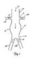
- FIG. 1is an illustration of a section of a diseased abdominal aorta 12 which can be treated by the aortic stent and stent-graft of the present invention.
- renal arteries 14A and 14Bextend from the aorta 12 at renal artery branch 16. Downstream from (i.e., on a first side of) the renal artery branch 16 is the iliac bifurcation 20 at which the aorta 12 divides (i.e., branches) into iliac arteries 18A and 18B.
- the stent and stent-graft of the present inventioncan be used to treat a diseased portion 26 of the aorta 12 which is located between the renal artery branch 16 and the iliac bifurcation 20.
- the diseased portion 26is represented in Figure 1 by an aneurysm (i.e., a weakened and expanded-diameter section).
- aneurysmi.e., a weakened and expanded-diameter section.
- the aneurysm or other disease attributes (i.e., indications) of the aorta 12 being treatedcan extend all the way to the renal arteries 14A and 14B, and/or beyond the iliac bifurcation 20 into the iliac arteries 18A and/or 18B.
- the stent and stent-graft of the present inventioncan make use of a portion 24 of the aorta 12 which is typically relatively healthy, and located upstream from the renal artery branch 16 (i.e., on a second side of the renal artery branch and opposite the branch from the diseased portion 26).
- Arrows 22are included in Figure 1 to illustrate the direction of blood flow through the aorta 12, renal arteries 14A and 14B and iliac arteries 18A and 18B.
- Stent 10is a tubular device and includes an upstream or fixation section 30, renal artery branch section 32 and downstream or diseased aorta section 34.
- Fixation section 30 and diseased aorta section 34are formed from two sets of oppositely-directed, parallel, spaced-apart and helically wound elongated strands or filaments 36.
- the sets of filaments 36are interwoven in an over and under braided configuration intersecting at points to form an open mesh or weave construction.
- Methods for fabricating stent structures such as fixation section 30 and diseased aorta section 34are generally known and disclosed, for example, in the Wallsten U.S.
- fixation section 30 and diseased aorta section 34are formed from structures which are substantially similar with the exception of their length.
- Other embodiments of the invention described belowinclude fixation and diseased aorta sections which are formed from stent structures having different characteristics.
- Renal artery branch section 32is formed by filaments 38 which have their opposite ends 40 connected to filaments 36 of the fixation section 30 and diseased aorta section 34.
- Six filaments 38(only four are visible) which are parallel to the longitudinal axis and equally spaced around the circumference of the stent 10 are shown in Figure 2.
- the opposite ends 40 of the filaments 38are connected to the fixation section 30 and diseased aorta section 34 by being wound around the filaments 36 of the fixation and diseased aorta sections.
- the ends 40 ofthe wound filaments 38can extend at an acute angle with respect to a longitudinal axis of the stent 10, and toward the diseased aorta section 34, to form a barb which can help anchor the stent 10 to the aorta 12 or other vessel in which the stent is implanted.
- the filaments 38 of the renal artery branch section 32can be attached to the fixation section 30 and diseased aorta section 34 by other known or methods such as welding.
- the porosity of the renal artery branch section 32is greater that that ofthe fixation section 30 and the diseased aorta section 34 (i.e., the density of the filaments 36 in the fixation and diseased aorta sections is greater than the density of the filaments 30 in the renal artery branch section).
- Stent 10is shown in its expanded or relaxed state in Figure 2, i.e., in the configuration it assumes when subjected to no external loads or stresses.
- the filaments 36are resilient, permitting the radial compression of the fixation section 30 and diseased aorta section 34 of stent 10 into a reduced-radius, extended-length configuration or state.
- the renal artery branch section 32can also be radially compressed into a reduced-radius configuration or state along with the fixation section 30 and diseased aorta section 34, thereby rendering the stent 10 suitable for delivery to the diseased aorta treatment site through a body vessel (i.e., transluminally).
- Stent 10is also self-expandable from the compressed state, and axially flexible.
- a wide variety of materialscan be used for the self-expanding stent filaments 36 and 38.
- Commonly used materialsinclude Elgiloy® and Phynox® spring alloys.
- Elgiloy® alloyis available from Carpenter Technology Corporation of Reading Pennsylvania.
- Phynox® alloyis available from Metal Imphy of Imphy, France.
- Other materials used for self-expanding stent filaments 36 and 38are 316 stainless steel and MP35N alloy which are available from Carpenter Technology Corporation and Latrobe Steel Company of Latrobe, Pennsylvania, and superelastic Nitinol alloy which is available from Shape Memory Applications of Santa Clara, California.
- the delivery devicescan include an elongated and flexible inner tube having proximal and distal ends.
- the stent 10is forced into its reduced-radius compressed state around the distal end of the inner tube, and constrained in the compressed state by an outer tube which surrounds the inner tube and stent 10.
- a deployment mechanismwhich can be actuated from the proximal end of the delivery device retracts the outer tube with respect to the inner tube, thereby allowing the stent 10 to self-expand into engagement with the inner wall of the aorta 12.
- FIG. 4is an illustration of the stent 10 implanted into the aorta 12 shown in Figure 1. As shown, fixation section 30 is located at and engaged with the relatively healthy portion 24 of the aorta 12 immediately opposite the renal arteries 14A and 14B from the iliac branch 20.
- Renal artery branch section 32is located at the renal artery branch 16 and extends across the locations at which the renal arteries 14A and 14B open into the aorta 12.
- the diseased aorta section 34 of the stent 10extends across the diseased portion 26 of the aorta 12, and therefore provides additional strength for this vessel.
- the support provided by diseased aorta section 34can help maintain a diseased aorta open in the presence of stenosis (not shown in Figures 1 and 2) which would otherwise reduce the blood flow capabilities of the vessel.
- the diseased aorta section 34 of stent 10extends from a location immediately downstream from the renal arteries 14A and 14B to a location immediately adjacent to the iliac arteries 18A and 18B.
- a first end 42 of the diseased aorta section 34 adjacent to the renal artery branch section 32is expanded radially outwardly into engagement with the inner walls of the aorta 12 adjacent to the renal arteries 14A and 14B.
- a second end 44 of the diseased aorta section 36is expanded radially outwardly into engagement with the inner walls of the aorta 12 adjacent to the location at which the iliac arteries 18A and 18B intersect the aorta.
- the diseased portion 26 of aorta 12 between the portions at which ends 42 and 44 ofthe section 34 engage the aortais weakened and extends outwardly beyond the stent 10.
- the amount of anchoring support provided by the relatively small surface area engagement of the ends 42 and 44 with the diseased portion 26 of the aorta 12may not be sufficient to securely maintain the stent section 34 in its implanted position.
- Fixation section 30 of the stent 10through its engagement with the relatively healthy portion 24 of the aorta 12 and its interconnection to the diseased aorta section 34 by filaments 38, provides substantial anchoring support for the diseased aorta section.
- the fixation section 30thereby enhances the positional stability of the implanted diseased aorta section 34. This enhanced positional stability is achieved without substantially restricting blood flow to the renal arteries 14A and 14B since the material density of the renal artery branch section 34 (i.e., the density of filaments 38 of stent 10) is relatively low.
- the term “porosity”also refers to the density or spacing of the filaments 38 (e.g., the amount of open space between the filaments with respect to the amount of space occupied by the filaments). Additional anchoring support for the stent 10 is provided by the barbed-type ends 40 of filaments 38 which engage the interior wall of the aorta 12.
- a stent 10 for implantation in the aorta 12 of an average size adult patientcan be between about 5 cm and 15 cm in length, and have an expanded state diameter between about 2 cm and 5 cm.
- the fixation section 30can be between about 1 cm and 5 cm in length.
- the renal artery branch section 32can be between about 1 cm and 5 cm in length.
- the diseased aorta section 34can be between about 4 cm and 15 cm in length.
- fixation section 30can be varied to change the amount of anchoring support being provided.
- the amount of anchoring supportwill increase with increasing length of the fixation section 30 (due to increased surface area of engagement), with increasing braid angle ⁇ of filaments 36 (illustrated in Figure 2, due to increased radial force generated by the section), and with increasing diameter (e.g., an outwardly flared end) and/or stiffness of filaments 36 (due to increased radial force of the section).
- these and other characteristics of the fixation sectioncan be decreased or otherwise varied to decrease the amount of anchoring support provided by the fixation section 30.
- the force exerted by the fixation section 30 on the aorta, and therefore the amount of anchoring support being provided,is the summation of the radial pressure exerted over the surface area of the section.
- the amount of anchoring supportcan therefore be varied by changing the radial pressure and surface area characteristics of the fixation section 30.
- the amount of anchoring support to be provided by the fixation section 30, and the features and characteristics of the fixation section to provide the support,can be optimized and selected to suit the indications of the particular diseased aorta 12 in which the stent 10 is to be implanted.
- the relative amount of anchoring support to be provided by the fixation section 30will often depend upon the amount of positional support that the diseased aorta section 34 is capable of generating in connection with the aorta 12 in which it is implanted.
- the diseased aorta section 34generates at least some anchoring support where its ends 42 and 44 engage the aorta 12.
- aortasthat are relatively more or less healthy than that shown at 12 in Figure 4 may be suitable for use with stents 10 having a fixation section 30 which provides less or more anchoring support, respectively, than the fixation section shown in Figure 4.
- the manner by which the fixation section 30 is configured to provide the desired amount of anchoring supportcan depend on the nature (e.g., relative health) of the portion 24 of the aorta 12 in which the fixation section is to be implanted. For example, if the portion 24 of aorta 12 in which the fixation section 30 is to be implanted is relatively weak, it may be advantageous to provide a fixation section which generates relatively low radial forces, but which is relatively long to achieve the desired anchoring support.
- Stent 210a second embodiment of the present invention, is illustrated in Figure 5.
- stent 210includes fixation section 230, renal artery branch section 232 and diseased aorta section 234.
- Sections 230, 232 and 234are all formed from self-expanding, braided filament stent structures of the type described above.
- Stent 210can be manufactured from a unitary braided filament stent structure by cutting and removing selected filaments from the portion of the structure to form the renal artery branch section 232.
- the density of the braided filaments 236 in the renal artery branch section 232is thereby reduced from the density of the filaments in the fixation section 230 and the diseased aorta section 234.
- stentssuch as 210 can be formed from thirty-eight to ninety-six filaments 236 (each of which is an individual wire and/or a pair of wires), with fifty to seventy-five percent of these filaments being cut and removed from the original structure to form the renal artery branch section 232.
- Stent 210can be implanted in a manner similar to that of stent 10 and described above.
- Stent 310a third embodiment of the present invention, is illustrated in Figure 6.
- the stent 310includes fixation section 330, renal artery branch section 332 and diseased aorta section 334.
- Sections 330, 332 and 334are all formed from self-expanding braided filament stent structures of the type described above.
- the braid angle ⁇ of the filaments 336 (and therefore the density and radial force)of the fixation section 330is greater than the braid angle of the filaments in the renal artery branch section 332 and the diseased aorta section 334.
- the braid angle of the filaments 336 in the renal artery branch section 332 and the diseased aorta section 334are substantially similar.
- Stent 310can be manufactured as a unitary braided filament structure by changing the braid angle during manufacture at the location corresponding to the intersection of the renal artery branch section 332 and the fixation section 330. The braid angle can also be changed by changing the braiding mandrel diameter, and by heat treating the stent at a given diameter. Stent 310 can be implanted in a patient in a manner similar to that of stent 10 and described above.
- Stent-graft 410a fourth embodiment ofthe present invention, is illustrated in Figure 7.
- a primary difference between stent 10 and stent-graft 410is that the stent-graft includes a tubular graft cover 450 incorporated on the diseased aorta section 434.
- the illustrated embodiment of stent-graft 410includes a diseased aorta section 434 formed from a braided filament stent structure of the type described above with reference to stent 10, and a separately fabricated graft cover 450 which is attached to the stent structure by adhesive, thread or filament stitching or other conventional techniques.
- the braided filament stent structureprovides the radially self-expandable features and characteristics described above, and thereby effectively functions as a support structure.
- the tubular graft cover 450effectively functions as a blood flow-shunting lumen, thereby supplementing the functionality of the portion of the aorta 12 in which the diseased aorta section 434 is implanted.
- the tubular graft cover 450is flexible and radially collapsible. When the braided filament stent structure is in its reduced-radius, compressed state, the graft cover 450 collapses, enabling the stent-graft 410 to be mounted on a deployment mechanism in the manner described above. The graft cover 450 is forced into and supported in its tubular, blood flow-shunting shape by the braided filament stent structure when the stent-graft 410 is deployed.
- Graft cover 450can be any of a variety of structures which have the characteristics described above (e.g., are flexible and radially collapsible) and which are sufficiently non-porous to shunt blood flow. Graft cover 450 can, for example, be formed from relatively tightly braided filaments of polymers such as polyethylene, polyethelyne terephalate and polyester. One suitable high molecular weight polyethylene is sold under the brand name "Spectra.” A suitable PET material is commercially available under the brand name "Dacron.” Alternatively, graft cover 450 can be formed from a sheet of material which is either itself impervious to blood flow, or covered with a coating which renders the material impervious. In still other embodiments, graft cover 450 is a film, sheet or tube of biocompatible material such as ePTFE.
- graft cover 450are formed by winding or spinning an extruded fiber onto a mandrel. Materials and methods for manufacturing graft covers 450 of these types are described in the following U.S. Patents: Wong, 4,475,972; Pinchuk et al., 4,738,740; Pinchuk, 5,229,431; and Dereume, 5,653,747.
- stent-graft 410include a diseased aorta section 434 in which the graft cover 450 is formed by multiple textile strands which are interbraided with each other and the filaments 436 of the stent structure to effectively form a composite stent and graft cover structure. Structures of these types which can be incorporated into stent-graft 410, and associated methods of manufacture, are described in European Patent Publication EP 0 804 934, and commonly assigned U.S. Application Serial Nos. 08/640,062, filed April 30, 1996, 08/640,091, filed April 30, 1996, 08/946,906, filed October 8, 1997, and 08/988,725, filed December 11, 1997.
- Stent-graft 510a fifth embodiment ofthe present invention, is illustrated in Figure 8.
- Fixation section 530, renal artery branch section 532 and the braided filament stent structure of the diseased aorta section 534are similar in structure and characteristics to those of stent 210 described above, and are indicated by like reference numbers.
- the graft cover 550 of stent-graft 510can be similar in structure and characteristics to that of graft cover 450 of stent graft 410 described above.
- the graft cover 550can be incorporated on the diseased aorta section 534 in a manner similar to the manner described above by which graft cover 450 is incorporated on the diseased aorta section 434 of stent-graft 410.
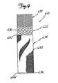
- Stent-graft 610a sixth embodiment of the present invention, is illustrated in Figure 9.
- Fixation section 630, renal artery branch section 632 and the braided filament stent structure of the diseased aorta section 634are similar in structure and characteristics to those of stent 310 described above, and are indicated by like reference numbers.
- the graft cover 650 of stent-graft 610can be similar in structure and characteristics to that of graft cover 450 of stent-graft 410 described above.
- the graft cover 650can be incorporated on the diseased aorta section 634 in a manner similar to the manner described above by which graft cover 450 is incorporated on the diseased aorta section 434 of stent-graft 410.
- Stent-grafts 430, 530 and 630 described aboveall include a tubular diseased aorta section 434, 534 and 634, respectively.
- Other embodiments of the inventioninclude bifurcated diseased aorta sections.
- Self-expanding bifurcated stent-graftsare, for example, described in the Alcime et al. U.S. Patent 5,632,772, the Dereume et al. U.S. Patent 5,639,278 and the Thompson and Du U.S. Patent Application Serial No.
- Bifurcated Stent Grafts of these typescan be used for indications in which the aortic aneurysm extends to the iliac bifurcation 20 ( Figure 1), or beyond the iliac bifurcation and into one or both of the iliac arteries 18A and 18B. Still other embodiments of the invention (also not shown) include an aorto-monoiliac diseased aorta section. Aorto-monoiliac stent-grafts of these types are used in connection with femoro-femoral bypass surgical procedures.
- FIG 10is an illustration of a portion of a carotid artery 80 which can be treated by the stent and stent-graft of the present invention.
- the common carotid artery 82divides into the internal carotid artery 84 and the external carotid artery 86 at the branch or bifurcation 88.
- the stent and stent-graft of the present inventionare configured to treat a diseased portion of carotid artery 80 which is located adjacent to the bifurcation 88.
- the diseased portion of carotid artery 80will include a section of the common carotid artery 82 immediately upstream from the bifurcation 88 and a portion of at least one of the internal carotid artery 84 and the external carotid artery 86 immediately downstream from the bifurcation.
- Arrows 90are included in Figure 10 to illustrate the direction of blood flow through the common carotid artery 82 (an upstream portion) and the internal and external carotid arteries 84 and 86, respectively (downstream portions).
- Stent-graft 710a seventh embodiment ofthe present invention, is illustrated in Figure 11.
- stent-graft 710includes an upstream section 730, a branch section 732 and a downstream section 734.
- the braided filament stent structures of stent-graft sections 730, 732 and 734can be portions of a unitary braided filament stent structure such as those described above, and are similar in structure and characteristics.
- the features and characteristics of the braided filament stent structures of upstream section 730 and/or downstream section 734can be varied to change the amount of anchoring support being provided by these sections.
- Graft covers 750 and 751are incorporated into the downstream section 734 and upstream section 730, respectively, of the stent-graft 710.
- the downstream section graft cover 750 and upstream section graft cover 751can be similar in structure and characteristics to those of graft cover 450 of stent-graft 410 described above.
- These graft covers 750 and 751have a relatively low porosity (i.e., are microporous), so they substantially prevent fluid flow after coagulation, but allow the exchange of nutrients.
- the graft covers 750 and 751also can be incorporated on the upstream section 730 and downstream section 734 in a manner similar to the manner described above by which the graft cover 450 is incorporated on the section 434 of stent-graft 410. Since the graft covers 750 and 751 have a relatively low porosity, the porosity of the interwoven filaments 736 of the branch section 732 will be relatively high with respect to the porosity ofthe downstream section 734 and upstream section 730.
- Stent-graft 710can be mounted on a delivery device in a manner similar to stent 10 described above. Similarly, the assembled device is inserted percutaneously into the femoral, brachial or radial artery and positioned and deployed like that of stent 10 described above.
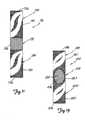
- Figure 12is an illustration of the stent-graft 710 implanted into the portion of the carotid artery 80 shown in Figure 10. As shown, upstream section 730 is located at and engaged with the common carotid artery 82 immediately upstream from the branch 88. Branch section 732 is located at the branch 88 and extends across the location at which the external carotid artery 86 opens into the common carotid artery 82.
- the downstream section 734 of the stent-graft 710is located at and engaged with the internal carotid artery 84 immediately downstream from the branch 88.
- Sections 730 and 734 of the stent-graft 710function as blood flow-shunting lumens to supplement the functionality of the portions of the arteries 82 and 84, respectively, in which they are implanted.
- the relatively high porosity branch section 732allows a portion of the blood flow through the common carotid artery 82 to flow into the external carotid artery 86.
- Stent-graft 710thereby effectively functions as a pseudobifurcated device.
- Stent-graft 810an eighth embodiment of the present invention, is illustrated in Figure 13.
- Upstream section 830, branch section 832 and downstream section 834are similar in structure and characteristics to those of stent-graft 710 described above, and are indicated by like reference numbers.
- Stent-graft 810can be implanted in a manner similar to that of stent-graft 710 described above.
- a primary difference between stent-grafts 710 and 810is that branch section 832 of stent-graft 810 includes a graft cover portion 853 with an aperture 855.
- graft cover portion 853is a section of a unitary graft cover which also includes portions 850 and 851 on the downstream section 834 and upstream section 830, respectively, of the stent-graft 810.
- Stent-graft 810can be implanted in a manner similar to that of stent-graft 710 described above, with the aperture 855 aligned with the intersection of the common carotid artery 82 and either the internal or external carotid artery 84 or 86, respectively, to function as a pseudobifurcated device.
- Stents and stent-grafts in accordance with the present inventionoffer a number of important advantages. They have the potential to be highly efficacious, especially in severely diseased aortas and carotid arteries that may not otherwise be capable of receiving conventional stents or stent-grafts. They can be manufactured so as to have selected ones of a wide range of characteristics, thereby enhancing the range of indications for which they can be used.
- the self-expanding properties of the devicesprovides a structure that is dynamically compliant. The stent and stent-graft can therefore expand and contract with fluctuations in the diameter of the vessels in which they are implanted.
- the dynamic compliancealso enables the device to change diameter over time with the vessel. For example, if the aneurysmal disease spreads to the fixation section of the vessel, the self-expanding device can continue to conform to the shape of the vessel wall. In contrast, rigid devices will remain at a fixed diameter and may not continue to engage the more recently diseased vessel portions.
- the self-expanding nature of the devicealso allows it to be reconstrained and repositioned by a development device. Since accurate placement of the device can be challenging, the ability to reposition the device enhances its usefulness.
Landscapes
- Health & Medical Sciences (AREA)
- Engineering & Computer Science (AREA)
- Biomedical Technology (AREA)
- Heart & Thoracic Surgery (AREA)
- Public Health (AREA)
- Transplantation (AREA)
- Cardiology (AREA)
- Veterinary Medicine (AREA)
- Oral & Maxillofacial Surgery (AREA)
- Vascular Medicine (AREA)
- Life Sciences & Earth Sciences (AREA)
- Animal Behavior & Ethology (AREA)
- General Health & Medical Sciences (AREA)
- Gastroenterology & Hepatology (AREA)
- Pulmonology (AREA)
- Prostheses (AREA)
- Media Introduction/Drainage Providing Device (AREA)
Description
Claims (12)
- An implantable medical device (10, 210, 410, 510, 610, 710, 810) for treatinga section of a patient's vessel having a vessel branch, a relatively healthy first vessel portion ona first side of the vessel branch, and a diseased vessel portion on a second side of the vesselbranch, said device includes:a fixation section (30, 230, 430, 530, 630, 730, 830) comprising a plurality of filaments(36, 236, 636, 736) which are helically wound in a braided configuration to form a tubular,radially compressible and self-expandable structure having a first porosity, whereby the term porosity refers to the density or spacingof the filaments;a diseased section (34,234,434,534,634,734,834) comprising a plurality of filaments(36, 236, 636, 736) which are helically wound in a braided configuration to form a tubular,radially compressible and self-expandable structure having a second porosity,characterised bya branch section (32, 232, 432, 532, 632, 732, 832) comprising a radially compressibleand expandable supportive structure, the branch section having a third porosity which is greaterthan the first porosity, said branch section connects the fixation section and the diseasedsection.
- An implantable medical device (10) as claimed in Claim 1 wherein the branchsection (32) includes a plurality of filaments (38) which are generally parallel to one another andhave opposite ends wrapped around filaments (36) of the fixation section (30) and the diseasedsection (34).
- An implantable medical device (210, 610, 710) as claimed in Claim 1 whereinthe branch section (232, 632, 732) includes filaments (236, 636, 736) which are helically woundin a braided configuration to form a tubular, radially compressible and self-expandable structure.
- An implantable medical device (10, 210, 610, 710) as claimed in any one ofClaims 1 to 3 wherein a radial pressure of the fixation section (30, 230, 630, 730) is greater thana radial pressure of the branch section (32, 232, 632, 732).
- An implantable medical device (10, 210, 610, 710) as claimed in any one ofClaims 1 to 4 wherein the radial pressure of the fixation section (30, 230, 630, 730) is greater thana radial pressure of the diseased section (34, 234, 634, 734).
- An implantable medical device (10, 210, 610, 710) as claimed in any one ofClaims 1 to 5 wherein the porosity of the supportive structure (32, 232, 632, 732) is greater thanthe porosity of the diseased section (34, 234, 634, 734).
- An implantable medical device (610) as claimed in anyone of Claims 1 to 6 andfurther including a radially-expandable membrane (650) coextensive with at least a length of thediseased section (634).
- An implantable medical device (610) as claimed in Claim 7 wherein themembrane is coextensive with at least 75% of a continuous length of the diseased section (634).
- An implantable medical device (610) as claimed in Claim 7 or Claim 8 whereinthe membrane (650) is formed of braided polymeric filaments.
- An implantable medical device (610) as claimed in Claim 9 wherein themembrane (650) is formed of filaments interbraided with one another and the filaments (636) ofthe self-expandable structure.
- An implantable medical device (10, 210, 710) as claimed in any precedingclaim wherein the free state diameters of the fixation section (30, 230, 730), diseased section (34,234, 734) and branch section (32, 232, 732) are equal to one another.
- An implantable medical device (710) as claimed in any preceding claim whereinthe fixation section (730) includes a radially-expandable and relatively low porosity membrane(751) coextensive with at least a portion of the length of the fixation section.
Priority Applications (1)
| Application Number | Priority Date | Filing Date | Title |
|---|---|---|---|
| EP04016944AEP1477134A3 (en) | 1997-05-27 | 1998-05-01 | Stent and stent-graft for treating branched vessels |
Applications Claiming Priority (3)
| Application Number | Priority Date | Filing Date | Title |
|---|---|---|---|
| US4774997P | 1997-05-27 | 1997-05-27 | |
| US47749P | 1997-05-27 | ||
| US2180498A | 1998-02-11 | 1998-02-11 |
Related Child Applications (2)
| Application Number | Title | Priority Date | Filing Date |
|---|---|---|---|
| EP04016944ADivisionEP1477134A3 (en) | 1997-05-27 | 1998-05-01 | Stent and stent-graft for treating branched vessels |
| EP04016944.3Division-Into | 2004-07-19 |
Publications (2)
| Publication Number | Publication Date |
|---|---|
| EP0880948A1 EP0880948A1 (en) | 1998-12-02 |
| EP0880948B1true EP0880948B1 (en) | 2004-10-27 |
Family
ID=49230952
Family Applications (1)
| Application Number | Title | Priority Date | Filing Date |
|---|---|---|---|
| EP98303442AExpired - LifetimeEP0880948B1 (en) | 1997-05-27 | 1998-05-01 | Stent and stent-graft for treating branched vessels |
Country Status (5)
| Country | Link |
|---|---|
| US (2) | US20040044396A1 (en) |
| EP (1) | EP0880948B1 (en) |
| JP (1) | JP4197762B2 (en) |
| CA (2) | CA2424551A1 (en) |
| DE (1) | DE69827192T2 (en) |
Cited By (6)
| Publication number | Priority date | Publication date | Assignee | Title |
|---|---|---|---|---|
| US6843802B1 (en) | 2000-11-16 | 2005-01-18 | Cordis Corporation | Delivery apparatus for a self expanding retractable stent |
| US7500988B1 (en) | 2000-11-16 | 2009-03-10 | Cordis Corporation | Stent for use in a stent graft |
| US7942925B2 (en) | 2001-07-09 | 2011-05-17 | Surpass Medical Ltd. | Implantable intraluminal device and method of using same in treating aneurysms |
| US7951557B2 (en) | 2003-04-27 | 2011-05-31 | Protalix Ltd. | Human lysosomal proteins from plant cell culture |
| US8945202B2 (en) | 2009-04-28 | 2015-02-03 | Endologix, Inc. | Fenestrated prosthesis |
| EP3169274B1 (en)* | 2014-07-16 | 2024-10-30 | JOTEC GmbH | Vascular prosthesis system and production method of the vascular prosthesis |
Families Citing this family (259)
| Publication number | Priority date | Publication date | Assignee | Title |
|---|---|---|---|---|
| EP1723931B1 (en)* | 1996-11-04 | 2012-01-04 | Advanced Stent Technologies, Inc. | Extendible stent apparatus and method for deploying the same |
| US6325826B1 (en)* | 1998-01-14 | 2001-12-04 | Advanced Stent Technologies, Inc. | Extendible stent apparatus |
| US7220275B2 (en)* | 1996-11-04 | 2007-05-22 | Advanced Stent Technologies, Inc. | Stent with protruding branch portion for bifurcated vessels |
| US6599316B2 (en)* | 1996-11-04 | 2003-07-29 | Advanced Stent Technologies, Inc. | Extendible stent apparatus |
| US7341598B2 (en) | 1999-01-13 | 2008-03-11 | Boston Scientific Scimed, Inc. | Stent with protruding branch portion for bifurcated vessels |
| US6835203B1 (en)* | 1996-11-04 | 2004-12-28 | Advanced Stent Technologies, Inc. | Extendible stent apparatus |
| US6951572B1 (en) | 1997-02-20 | 2005-10-04 | Endologix, Inc. | Bifurcated vascular graft and method and apparatus for deploying same |
| US20040130599A1 (en)* | 1997-07-15 | 2004-07-08 | Silverbrook Research Pty Ltd | Ink jet printhead with amorphous ceramic chamber |
| FR2775182B1 (en)* | 1998-02-25 | 2000-07-28 | Legona Anstalt | DEVICE FORMING INTRACORPOREAL ENDOLUMINAL ANDOPROTHESIS, IN PARTICULAR AORTIC ABDOMINAL |
| US6290731B1 (en)* | 1998-03-30 | 2001-09-18 | Cordis Corporation | Aortic graft having a precursor gasket for repairing an abdominal aortic aneurysm |
| US6887268B2 (en) | 1998-03-30 | 2005-05-03 | Cordis Corporation | Extension prosthesis for an arterial repair |
| US6755856B2 (en)* | 1998-09-05 | 2004-06-29 | Abbott Laboratories Vascular Enterprises Limited | Methods and apparatus for stenting comprising enhanced embolic protection, coupled with improved protection against restenosis and thrombus formation |
| US6733523B2 (en)* | 1998-12-11 | 2004-05-11 | Endologix, Inc. | Implantable vascular graft |
| US6660030B2 (en) | 1998-12-11 | 2003-12-09 | Endologix, Inc. | Bifurcation graft deployment catheter |
| US6187036B1 (en) | 1998-12-11 | 2001-02-13 | Endologix, Inc. | Endoluminal vascular prosthesis |
| US8257425B2 (en)* | 1999-01-13 | 2012-09-04 | Boston Scientific Scimed, Inc. | Stent with protruding branch portion for bifurcated vessels |
| ES2259996T3 (en)* | 1999-01-22 | 2006-11-01 | Gore Enterprise Holdings, Inc. | ENDOPROTESIS COVER. |
| US6673102B1 (en) | 1999-01-22 | 2004-01-06 | Gore Enterprises Holdings, Inc. | Covered endoprosthesis and delivery system |
| CA2360551C (en)* | 1999-01-27 | 2009-12-22 | Scimed Life Systems, Inc. | Bifurcation stent delivery system |
| US6673089B1 (en) | 1999-03-11 | 2004-01-06 | Mindguard Ltd. | Implantable stroke treating device |
| IL128938A0 (en) | 1999-03-11 | 2000-02-17 | Mind Guard Ltd | Implantable stroke treating device |
| US6585756B1 (en)* | 1999-05-14 | 2003-07-01 | Ernst P. Strecker | Implantable lumen prosthesis |
| FR2797388B1 (en) | 1999-08-09 | 2001-11-30 | Novatech Inc | STRUCTURE OF A PROSTHESIS INTENDED TO BE IMPLANTED IN A HUMAN OR ANIMAL DUCT AND PROSTHESIS PROVIDED WITH SUCH A STRUCTURE |
| FR2797389B1 (en) | 1999-08-09 | 2001-11-30 | Novatech Inc | BIFURCED AORTIC PROSTHESIS |
| FR2797761B1 (en) | 1999-08-24 | 2002-03-22 | Novatech Inc | DEVICE FOR PROVIDING RELEASE IN A HUMAN OR ANIMAL CONDUIT OF AN OBJECT, IN PARTICULAR A PROSTHESIS, AND IMPLANTATION SYSTEM COMPRISING A CATHETER AND SUCH A DEVICE |
| WO2001021095A2 (en)* | 1999-09-23 | 2001-03-29 | Advanced Stent Technologies, Inc. | Bifurcation stent system and method |
| US6344056B1 (en)* | 1999-12-29 | 2002-02-05 | Edwards Lifesciences Corp. | Vascular grafts for bridging a vessel side branch |
| US6585758B1 (en) | 1999-11-16 | 2003-07-01 | Scimed Life Systems, Inc. | Multi-section filamentary endoluminal stent |
| US6610087B1 (en) | 1999-11-16 | 2003-08-26 | Scimed Life Systems, Inc. | Endoluminal stent having a matched stiffness region and/or a stiffness gradient and methods for providing stent kink resistance |
| US6663667B2 (en) | 1999-12-29 | 2003-12-16 | Edwards Lifesciences Corporation | Towel graft means for enhancing tissue ingrowth in vascular grafts |
| US6334866B1 (en)* | 2000-01-14 | 2002-01-01 | William H. Wall | Stent device for performing endovascular repair of aneurysms |
| AU769900B2 (en)* | 2000-03-03 | 2004-02-05 | Cook Medical Technologies Llc | Endovascular device having a stent |
| IL137326A0 (en)* | 2000-07-17 | 2001-07-24 | Mind Guard Ltd | Implantable braided stroke preventing device and method of manufacturing |
| US7267685B2 (en) | 2000-11-16 | 2007-09-11 | Cordis Corporation | Bilateral extension prosthesis and method of delivery |
| US7229472B2 (en) | 2000-11-16 | 2007-06-12 | Cordis Corporation | Thoracic aneurysm repair prosthesis and system |
| US7314483B2 (en) | 2000-11-16 | 2008-01-01 | Cordis Corp. | Stent graft with branch leg |
| US6942692B2 (en) | 2000-11-16 | 2005-09-13 | Cordis Corporation | Supra-renal prosthesis and renal artery bypass |
| US20030097169A1 (en) | 2001-02-26 | 2003-05-22 | Brucker Gregory G. | Bifurcated stent and delivery system |
| US10105209B2 (en) | 2001-04-11 | 2018-10-23 | Andrew Kerr | Stent/graft assembly |
| US9937066B2 (en) | 2001-04-11 | 2018-04-10 | Andre Kerr | Stent/graft assembly |
| US20040215322A1 (en)* | 2001-07-06 | 2004-10-28 | Andrew Kerr | Stent/graft assembly |
| DE10118944B4 (en) | 2001-04-18 | 2013-01-31 | Merit Medical Systems, Inc. | Removable, essentially cylindrical implants |
| AU2002320456A1 (en) | 2001-07-26 | 2003-02-17 | Alveolus Inc. | Removable stent and method of using the same |
| JP4608672B2 (en)* | 2001-09-17 | 2011-01-12 | Junken Medical株式会社 | Stented graft |
| US20030074055A1 (en)* | 2001-10-17 | 2003-04-17 | Haverkost Patrick A. | Method and system for fixation of endoluminal devices |
| US7147661B2 (en) | 2001-12-20 | 2006-12-12 | Boston Scientific Santa Rosa Corp. | Radially expandable stent |
| JP4331610B2 (en)* | 2001-12-20 | 2009-09-16 | トリバスキュラー2,インコーポレイティド | Advanced endovascular graft |
| US7163553B2 (en) | 2001-12-28 | 2007-01-16 | Advanced Cardiovascular Systems, Inc. | Intravascular stent and method of use |
| US20030135265A1 (en)* | 2002-01-04 | 2003-07-17 | Stinson Jonathan S. | Prostheses implantable in enteral vessels |
| US7326237B2 (en) | 2002-01-08 | 2008-02-05 | Cordis Corporation | Supra-renal anchoring prosthesis |
| US7029494B2 (en)* | 2002-02-08 | 2006-04-18 | Scimed Life Systems, Inc. | Braided modular stent with hourglass-shaped interfaces |
| US20030195609A1 (en)* | 2002-04-10 | 2003-10-16 | Scimed Life Systems, Inc. | Hybrid stent |
| US7887575B2 (en)* | 2002-05-22 | 2011-02-15 | Boston Scientific Scimed, Inc. | Stent with segmented graft |
| US20030220683A1 (en)* | 2002-05-22 | 2003-11-27 | Zarouhi Minasian | Endoluminal device having barb assembly and method of using same |
| US20050033405A1 (en)* | 2002-08-15 | 2005-02-10 | Gmp/Cardiac Care, Inc. | Rail stent-graft for repairing abdominal aortic aneurysm |
| KR100893070B1 (en)* | 2002-09-19 | 2009-04-17 | 엘지전자 주식회사 | Method and apparatus for providing and receiving multicast service in wireless communication system |
| US7527644B2 (en) | 2002-11-05 | 2009-05-05 | Alveolus Inc. | Stent with geometry determinated functionality and method of making the same |
| US7959671B2 (en) | 2002-11-05 | 2011-06-14 | Merit Medical Systems, Inc. | Differential covering and coating methods |
| US7875068B2 (en) | 2002-11-05 | 2011-01-25 | Merit Medical Systems, Inc. | Removable biliary stent |
| US7637942B2 (en)* | 2002-11-05 | 2009-12-29 | Merit Medical Systems, Inc. | Coated stent with geometry determinated functionality and method of making the same |
| US7001425B2 (en)* | 2002-11-15 | 2006-02-21 | Scimed Life Systems, Inc. | Braided stent method for its manufacture |
| JP4829098B2 (en)* | 2003-01-14 | 2011-11-30 | ザ クリーヴランド クリニック ファウンデーション | Branch vessel endoluminal device |
| US9125733B2 (en)* | 2003-01-14 | 2015-09-08 | The Cleveland Clinic Foundation | Branched vessel endoluminal device |
| US6945992B2 (en)* | 2003-04-22 | 2005-09-20 | Medtronic Vascular, Inc. | Single-piece crown stent |
| US20100196345A1 (en)* | 2003-04-27 | 2010-08-05 | Protalix | Production of high mannose proteins in plant culture |
| US8298280B2 (en) | 2003-08-21 | 2012-10-30 | Boston Scientific Scimed, Inc. | Stent with protruding branch portion for bifurcated vessels |
| US20050096725A1 (en) | 2003-10-29 | 2005-05-05 | Pomeranz Mark L. | Expandable stent having removable slat members |
| US7070616B2 (en)* | 2003-10-31 | 2006-07-04 | Cordis Corporation | Implantable valvular prosthesis |
| EP3424463A1 (en)* | 2003-11-08 | 2019-01-09 | Cook Medical Technologies LLC | Aorta and branch vessel stent grafts and system |
| JP4464972B2 (en) | 2003-12-17 | 2010-05-19 | クック・インコーポレイテッド | Interconnected leg extensions for endoluminal prostheses |
| US8007528B2 (en)* | 2004-03-17 | 2011-08-30 | Boston Scientific Scimed, Inc. | Bifurcated stent |
| US9039724B2 (en)* | 2004-03-19 | 2015-05-26 | Aga Medical Corporation | Device for occluding vascular defects |
| US8313505B2 (en)* | 2004-03-19 | 2012-11-20 | Aga Medical Corporation | Device for occluding vascular defects |
| US8398670B2 (en) | 2004-03-19 | 2013-03-19 | Aga Medical Corporation | Multi-layer braided structures for occluding vascular defects and for occluding fluid flow through portions of the vasculature of the body |
| US8777974B2 (en)* | 2004-03-19 | 2014-07-15 | Aga Medical Corporation | Multi-layer braided structures for occluding vascular defects |
| US8747453B2 (en)* | 2008-02-18 | 2014-06-10 | Aga Medical Corporation | Stent/stent graft for reinforcement of vascular abnormalities and associated method |
| US7674284B2 (en) | 2004-03-31 | 2010-03-09 | Cook Incorporated | Endoluminal graft |
| US8048140B2 (en)* | 2004-03-31 | 2011-11-01 | Cook Medical Technologies Llc | Fenestrated intraluminal stent system |
| JP4713573B2 (en) | 2004-03-31 | 2011-06-29 | クック・インコーポレイテッド | Stent deployment device |
| US8267985B2 (en) | 2005-05-25 | 2012-09-18 | Tyco Healthcare Group Lp | System and method for delivering and deploying an occluding device within a vessel |
| CA2758946C (en) | 2004-05-25 | 2014-10-21 | Tyco Healthcare Group Lp | Vascular stenting for aneurysms |
| US8623067B2 (en) | 2004-05-25 | 2014-01-07 | Covidien Lp | Methods and apparatus for luminal stenting |
| CA2565106C (en)* | 2004-05-25 | 2013-11-05 | Chestnut Medical Technologies, Inc. | Flexible vascular occluding device |
| US8617234B2 (en) | 2004-05-25 | 2013-12-31 | Covidien Lp | Flexible vascular occluding device |
| US20060206200A1 (en) | 2004-05-25 | 2006-09-14 | Chestnut Medical Technologies, Inc. | Flexible vascular occluding device |
| JP5054524B2 (en) | 2004-06-08 | 2012-10-24 | アドバンスド ステント テクノロジーズ, インコーポレイテッド | Stent with protruding branch for branch pipe |
| US7763065B2 (en)* | 2004-07-21 | 2010-07-27 | Reva Medical, Inc. | Balloon expandable crush-recoverable stent device |
| US7887579B2 (en)* | 2004-09-29 | 2011-02-15 | Merit Medical Systems, Inc. | Active stent |
| US7156871B2 (en) | 2004-10-28 | 2007-01-02 | Cordis Neurovascular, Inc. | Expandable stent having a stabilized portion |
| US7147659B2 (en)* | 2004-10-28 | 2006-12-12 | Cordis Neurovascular, Inc. | Expandable stent having a dissolvable portion |
| US9427340B2 (en)* | 2004-12-14 | 2016-08-30 | Boston Scientific Scimed, Inc. | Stent with protruding branch portion for bifurcated vessels |
| KR100614654B1 (en)* | 2005-01-04 | 2006-08-22 | 삼성전자주식회사 | Wireless transmitters provide effective power compensation for output changes with temperature and process |
| EP1838242A2 (en)* | 2005-01-21 | 2007-10-03 | Gen 4, LLC | Modular stent graft employing bifurcated graft and leg locking stent elements |
| US9597209B2 (en) | 2005-02-17 | 2017-03-21 | Khoury Medical Devices, Llc | Vascular endograft |
| US7828837B2 (en) | 2005-02-17 | 2010-11-09 | Khoury Medical Devices, LLC. | Vascular endograft |
| WO2006113501A1 (en) | 2005-04-13 | 2006-10-26 | The Cleveland Clinic Foundation | Endoluminal prosthesis |
| US7731654B2 (en)* | 2005-05-13 | 2010-06-08 | Merit Medical Systems, Inc. | Delivery device with viewing window and associated method |
| AU2005332044B2 (en) | 2005-05-25 | 2012-01-19 | Covidien Lp | System and method for delivering and deploying and occluding device within a vessel |
| US8317855B2 (en)* | 2005-05-26 | 2012-11-27 | Boston Scientific Scimed, Inc. | Crimpable and expandable side branch cell |
| US8480728B2 (en)* | 2005-05-26 | 2013-07-09 | Boston Scientific Scimed, Inc. | Stent side branch deployment initiation geometry |
| US20060271161A1 (en)* | 2005-05-26 | 2006-11-30 | Boston Scientific Scimed, Inc. | Selective treatment of stent side branch petals |
| WO2007002863A2 (en)* | 2005-06-28 | 2007-01-04 | Venkatesh Ramaiah | Non-occlusive, retrievable dilation system |
| US20080114439A1 (en)* | 2005-06-28 | 2008-05-15 | Venkatesh Ramaiah | Non-occluding dilation device |
| WO2007013977A2 (en)* | 2005-07-21 | 2007-02-01 | The Research Foundation Of State University Of New York | Stent vascular intervention device and methods for treating aneurysms |
| WO2007014088A2 (en)* | 2005-07-25 | 2007-02-01 | Cook Incorporated | Intraluminal prosthesis and stent |
| US7731741B2 (en) | 2005-09-08 | 2010-06-08 | Boston Scientific Scimed, Inc. | Inflatable bifurcation stent |
| US8038706B2 (en)* | 2005-09-08 | 2011-10-18 | Boston Scientific Scimed, Inc. | Crown stent assembly |
| US8043366B2 (en)* | 2005-09-08 | 2011-10-25 | Boston Scientific Scimed, Inc. | Overlapping stent |
| CA2627554A1 (en)* | 2005-10-27 | 2007-05-03 | Martin S. Dieck | Partially covered stent devices and methods of use |
| US20070112418A1 (en) | 2005-11-14 | 2007-05-17 | Boston Scientific Scimed, Inc. | Stent with spiral side-branch support designs |
| US20070150042A1 (en)* | 2005-12-05 | 2007-06-28 | Balaji Malur R | Stents with beveled ends and methods of use thereof |
| DE102006040301A1 (en)* | 2005-12-06 | 2008-03-06 | Düring, Klaus, Dr. | Device for splinting a cavity, organ path and / or vessel |
| US8343211B2 (en)* | 2005-12-14 | 2013-01-01 | Boston Scientific Scimed, Inc. | Connectors for bifurcated stent |
| US8435284B2 (en)* | 2005-12-14 | 2013-05-07 | Boston Scientific Scimed, Inc. | Telescoping bifurcated stent |
| US7540881B2 (en) | 2005-12-22 | 2009-06-02 | Boston Scientific Scimed, Inc. | Bifurcation stent pattern |
| US8900287B2 (en)* | 2006-01-13 | 2014-12-02 | Aga Medical Corporation | Intravascular deliverable stent for reinforcement of abdominal aortic aneurysm |
| US8778008B2 (en)* | 2006-01-13 | 2014-07-15 | Aga Medical Corporation | Intravascular deliverable stent for reinforcement of vascular abnormalities |
| US20070179599A1 (en)* | 2006-01-31 | 2007-08-02 | Icon Medical Corp. | Vascular protective device |
| US8152833B2 (en) | 2006-02-22 | 2012-04-10 | Tyco Healthcare Group Lp | Embolic protection systems having radiopaque filter mesh |
| US20070208411A1 (en)* | 2006-03-06 | 2007-09-06 | Boston Scientific Scimed, Inc. | Bifurcated stent with surface area gradient |
| US20070208419A1 (en)* | 2006-03-06 | 2007-09-06 | Boston Scientific Scimed, Inc. | Bifurcation stent with uniform side branch projection |
| US7833264B2 (en)* | 2006-03-06 | 2010-11-16 | Boston Scientific Scimed, Inc. | Bifurcated stent |
| US20070208415A1 (en)* | 2006-03-06 | 2007-09-06 | Kevin Grotheim | Bifurcated stent with controlled drug delivery |
| US8298278B2 (en)* | 2006-03-07 | 2012-10-30 | Boston Scientific Scimed, Inc. | Bifurcated stent with improvement securement |
| US20070233233A1 (en)* | 2006-03-31 | 2007-10-04 | Boston Scientific Scimed, Inc | Tethered expansion columns for controlled stent expansion |
| AU2007240703C1 (en) | 2006-04-19 | 2012-06-14 | Cleveland Clinic Foundation | Twin bifurcated stent graft |
| EP2051673A2 (en) | 2006-06-23 | 2009-04-29 | Boston Scientific Limited | Bifurcated stent with twisted hinges |
| US9408607B2 (en) | 2009-07-02 | 2016-08-09 | Edwards Lifesciences Cardiaq Llc | Surgical implant devices and methods for their manufacture and use |
| US9585743B2 (en) | 2006-07-31 | 2017-03-07 | Edwards Lifesciences Cardiaq Llc | Surgical implant devices and methods for their manufacture and use |
| EP3360509B1 (en) | 2006-07-31 | 2022-06-22 | Syntheon TAVR, LLC | Sealable endovascular implants |
| GB0617219D0 (en) | 2006-08-31 | 2006-10-11 | Barts & London Nhs Trust | Blood vessel prosthesis and delivery apparatus |
| US8216267B2 (en)* | 2006-09-12 | 2012-07-10 | Boston Scientific Scimed, Inc. | Multilayer balloon for bifurcated stent delivery and methods of making and using the same |
| US7951191B2 (en) | 2006-10-10 | 2011-05-31 | Boston Scientific Scimed, Inc. | Bifurcated stent with entire circumferential petal |
| US8206429B2 (en) | 2006-11-02 | 2012-06-26 | Boston Scientific Scimed, Inc. | Adjustable bifurcation catheter incorporating electroactive polymer and methods of making and using the same |
| US7842082B2 (en) | 2006-11-16 | 2010-11-30 | Boston Scientific Scimed, Inc. | Bifurcated stent |
| US7959668B2 (en) | 2007-01-16 | 2011-06-14 | Boston Scientific Scimed, Inc. | Bifurcated stent |
| ES2624595T3 (en) | 2007-03-05 | 2017-07-17 | Endospan Ltd | Bifurcated, supportive, expandable endoluminal grafts with multiple components and methods for use |
| KR100847432B1 (en)* | 2007-03-14 | 2008-07-21 | 주식회사 에스앤지바이오텍 | Lumen extension stent |
| US8118861B2 (en)* | 2007-03-28 | 2012-02-21 | Boston Scientific Scimed, Inc. | Bifurcation stent and balloon assemblies |
| US8647376B2 (en)* | 2007-03-30 | 2014-02-11 | Boston Scientific Scimed, Inc. | Balloon fold design for deployment of bifurcated stent petal architecture |
| WO2008135991A2 (en) | 2007-05-07 | 2008-11-13 | Protalix Ltd. | Large scale disposable bioreactor |
| US8128679B2 (en) | 2007-05-23 | 2012-03-06 | Abbott Laboratories Vascular Enterprises Limited | Flexible stent with torque-absorbing connectors |
| US8979918B2 (en) | 2007-07-06 | 2015-03-17 | Daisuke Kawabe | Stent, microcatheter, braiding apparatus for continuous hoselike body, and process for manufacturing stent |
| US9814611B2 (en) | 2007-07-31 | 2017-11-14 | Edwards Lifesciences Cardiaq Llc | Actively controllable stent, stent graft, heart valve and method of controlling same |
| US9566178B2 (en) | 2010-06-24 | 2017-02-14 | Edwards Lifesciences Cardiaq Llc | Actively controllable stent, stent graft, heart valve and method of controlling same |
| US7959669B2 (en) | 2007-09-12 | 2011-06-14 | Boston Scientific Scimed, Inc. | Bifurcated stent with open ended side branch support |
| US8066755B2 (en) | 2007-09-26 | 2011-11-29 | Trivascular, Inc. | System and method of pivoted stent deployment |
| US8663309B2 (en) | 2007-09-26 | 2014-03-04 | Trivascular, Inc. | Asymmetric stent apparatus and method |
| US8226701B2 (en) | 2007-09-26 | 2012-07-24 | Trivascular, Inc. | Stent and delivery system for deployment thereof |
| US10159557B2 (en) | 2007-10-04 | 2018-12-25 | Trivascular, Inc. | Modular vascular graft for low profile percutaneous delivery |
| US8328861B2 (en) | 2007-11-16 | 2012-12-11 | Trivascular, Inc. | Delivery system and method for bifurcated graft |
| US8083789B2 (en) | 2007-11-16 | 2011-12-27 | Trivascular, Inc. | Securement assembly and method for expandable endovascular device |
| US7833266B2 (en) | 2007-11-28 | 2010-11-16 | Boston Scientific Scimed, Inc. | Bifurcated stent with drug wells for specific ostial, carina, and side branch treatment |
| CN101965162B (en)* | 2007-12-15 | 2014-12-10 | 恩多斯潘有限公司 | Extra-vascular wrapping for treating aneurysmatic aorta in conjunction with endovascular stent-graft and methods thereof |
| US8920488B2 (en) | 2007-12-20 | 2014-12-30 | Abbott Laboratories Vascular Enterprises Limited | Endoprosthesis having a stable architecture |
| US8002816B2 (en)* | 2007-12-21 | 2011-08-23 | Cleveland Clinic Foundation | Prosthesis for implantation in aorta and method of using same |
| US8277501B2 (en) | 2007-12-21 | 2012-10-02 | Boston Scientific Scimed, Inc. | Bi-stable bifurcated stent petal geometry |
| US8747456B2 (en) | 2007-12-31 | 2014-06-10 | Boston Scientific Scimed, Inc. | Bifurcation stent delivery system and methods |
| US8163004B2 (en)* | 2008-02-18 | 2012-04-24 | Aga Medical Corporation | Stent graft for reinforcement of vascular abnormalities and associated method |
| WO2009105699A1 (en) | 2008-02-22 | 2009-08-27 | Endologix, Inc. | Design and method of placement of a graft or graft system |
| GB0803302D0 (en)* | 2008-02-22 | 2008-04-02 | Barts & London Nhs Trust | Blood vessel prosthesis and delivery apparatus |
| US8236040B2 (en) | 2008-04-11 | 2012-08-07 | Endologix, Inc. | Bifurcated graft deployment systems and methods |
| US20090259290A1 (en)* | 2008-04-14 | 2009-10-15 | Medtronic Vascular, Inc. | Fenestration Segment Stent-Graft and Fenestration Method |
| US20090264987A1 (en)* | 2008-04-18 | 2009-10-22 | Medtronic Vascular, Inc. | Stent Graft Delivery System and Method of Use |
| WO2009140437A1 (en) | 2008-05-13 | 2009-11-19 | Nfocus Neuromedical, Inc. | Braid implant delivery systems |
| US8932340B2 (en) | 2008-05-29 | 2015-01-13 | Boston Scientific Scimed, Inc. | Bifurcated stent and delivery system |
| EP2520320B1 (en) | 2008-07-01 | 2016-11-02 | Endologix, Inc. | Catheter system |
| CN102245129B (en) | 2008-07-21 | 2015-03-18 | 詹妮弗·K·怀特 | Repositionable intraluminal support structures and their applications |
| CA2734493C (en)* | 2008-08-19 | 2016-09-27 | Tissuegen, Inc. | Self-expanding medical device |
| US20100049307A1 (en)* | 2008-08-25 | 2010-02-25 | Aga Medical Corporation | Stent graft having extended landing area and method for using the same |
| US8353943B2 (en) | 2008-08-29 | 2013-01-15 | Cook Medical Technologies Llc | Variable weave graft with metal strand reinforcement for in situ fenestration |
| US9149377B2 (en)* | 2008-10-10 | 2015-10-06 | Veryan Medical Ltd. | Stent suitable for deployment in a blood vessel |
| CN101780306B (en)* | 2009-01-21 | 2013-04-17 | 王宏飞 | Medical inner support hollow tubular sac catheter |
| US8151682B2 (en) | 2009-01-26 | 2012-04-10 | Boston Scientific Scimed, Inc. | Atraumatic stent and method and apparatus for making the same |
| JP2012525239A (en) | 2009-05-01 | 2012-10-22 | エンドロジックス、インク | Transcutaneous methods and devices for treating dissociation (priority information and incorporation by reference) |
| US10772717B2 (en) | 2009-05-01 | 2020-09-15 | Endologix, Inc. | Percutaneous method and device to treat dissections |
| US8784467B2 (en)* | 2009-05-15 | 2014-07-22 | Lemaitre Vascular, Inc. | Non-occlusive dilation devices |
| CA3009244C (en) | 2009-06-23 | 2020-04-28 | Endospan Ltd. | Vascular prostheses for treating aneurysms |
| WO2011004374A1 (en) | 2009-07-09 | 2011-01-13 | Endospan Ltd. | Apparatus for closure of a lumen and methods of using the same |
| WO2011008989A2 (en) | 2009-07-15 | 2011-01-20 | Endologix, Inc. | Stent graft |
| WO2011017123A2 (en) | 2009-07-27 | 2011-02-10 | Endologix, Inc. | Stent graft |
| CN102740807B (en) | 2009-11-30 | 2015-11-25 | 恩多斯潘有限公司 | Multi-component stent-graft system for implantation into vessels with multiple branches |
| EP2509535B1 (en)* | 2009-12-08 | 2016-12-07 | Endospan Ltd | Endovascular stent-graft system with fenestrated and crossing stent-grafts |
| WO2011080738A1 (en) | 2009-12-31 | 2011-07-07 | Endospan Ltd. | Endovascular flow direction indicator |
| US9468517B2 (en) | 2010-02-08 | 2016-10-18 | Endospan Ltd. | Thermal energy application for prevention and management of endoleaks in stent-grafts |
| US20120109279A1 (en) | 2010-11-02 | 2012-05-03 | Endologix, Inc. | Apparatus and method of placement of a graft or graft system |
| US9393100B2 (en) | 2010-11-17 | 2016-07-19 | Endologix, Inc. | Devices and methods to treat vascular dissections |
| US9839540B2 (en) | 2011-01-14 | 2017-12-12 | W. L. Gore & Associates, Inc. | Stent |
| US10166128B2 (en) | 2011-01-14 | 2019-01-01 | W. L. Gore & Associates. Inc. | Lattice |
| CA2826022A1 (en) | 2011-02-03 | 2012-08-09 | Endospan Ltd. | Implantable medical devices constructed of shape memory material |
| US20120203329A1 (en)* | 2011-02-07 | 2012-08-09 | Heuser Richard R | Bifurcated stent and method of use |
| WO2012111006A1 (en) | 2011-02-17 | 2012-08-23 | Endospan Ltd. | Vascular bands and delivery systems therefor |
| US8808350B2 (en) | 2011-03-01 | 2014-08-19 | Endologix, Inc. | Catheter system and methods of using same |
| WO2012117395A1 (en) | 2011-03-02 | 2012-09-07 | Endospan Ltd. | Reduced-strain extra- vascular ring for treating aortic aneurysm |
| US8574287B2 (en) | 2011-06-14 | 2013-11-05 | Endospan Ltd. | Stents incorporating a plurality of strain-distribution locations |
| US8951298B2 (en) | 2011-06-21 | 2015-02-10 | Endospan Ltd. | Endovascular system with circumferentially-overlapping stent-grafts |
| US9254209B2 (en) | 2011-07-07 | 2016-02-09 | Endospan Ltd. | Stent fixation with reduced plastic deformation |
| US9839510B2 (en) | 2011-08-28 | 2017-12-12 | Endospan Ltd. | Stent-grafts with post-deployment variable radial displacement |
| GB2494632A (en)* | 2011-09-09 | 2013-03-20 | Isis Innovation | Stent and method of inserting a stent into a delivery catheter |
| US9827093B2 (en) | 2011-10-21 | 2017-11-28 | Edwards Lifesciences Cardiaq Llc | Actively controllable stent, stent graft, heart valve and method of controlling same |
| US9427339B2 (en) | 2011-10-30 | 2016-08-30 | Endospan Ltd. | Triple-collar stent-graft |
| US8986368B2 (en) | 2011-10-31 | 2015-03-24 | Merit Medical Systems, Inc. | Esophageal stent with valve |
| US9597204B2 (en) | 2011-12-04 | 2017-03-21 | Endospan Ltd. | Branched stent-graft system |
| JP2013135794A (en)* | 2011-12-28 | 2013-07-11 | Asahi Intecc Co Ltd | Flow diverter stent |
| DE102012100839A1 (en)* | 2012-02-01 | 2013-08-01 | Jotec Gmbh | Intraluminal vascular prosthesis |
| US8992595B2 (en) | 2012-04-04 | 2015-03-31 | Trivascular, Inc. | Durable stent graft with tapered struts and stable delivery methods and devices |
| US9498363B2 (en) | 2012-04-06 | 2016-11-22 | Trivascular, Inc. | Delivery catheter for endovascular device |
| JP6220386B2 (en) | 2012-05-14 | 2017-10-25 | シー・アール・バード・インコーポレーテッドC R Bard Incorporated | Uniformly expandable stent |
| WO2013171730A1 (en) | 2012-05-15 | 2013-11-21 | Endospan Ltd. | Stent-graft with fixation elements that are radially confined for delivery |
| US9155647B2 (en) | 2012-07-18 | 2015-10-13 | Covidien Lp | Methods and apparatus for luminal stenting |
| US9283072B2 (en) | 2012-07-25 | 2016-03-15 | W. L. Gore & Associates, Inc. | Everting transcatheter valve and methods |
| US10376360B2 (en) | 2012-07-27 | 2019-08-13 | W. L. Gore & Associates, Inc. | Multi-frame prosthetic valve apparatus and methods |
| US9301831B2 (en) | 2012-10-30 | 2016-04-05 | Covidien Lp | Methods for attaining a predetermined porosity of a vascular device |
| US9452070B2 (en) | 2012-10-31 | 2016-09-27 | Covidien Lp | Methods and systems for increasing a density of a region of a vascular device |
| US9943427B2 (en) | 2012-11-06 | 2018-04-17 | Covidien Lp | Shaped occluding devices and methods of using the same |
| US9931193B2 (en) | 2012-11-13 | 2018-04-03 | W. L. Gore & Associates, Inc. | Elastic stent graft |
| US10321986B2 (en) | 2012-12-19 | 2019-06-18 | W. L. Gore & Associates, Inc. | Multi-frame prosthetic heart valve |
| US9737398B2 (en) | 2012-12-19 | 2017-08-22 | W. L. Gore & Associates, Inc. | Prosthetic valves, frames and leaflets and methods thereof |
| US9968443B2 (en) | 2012-12-19 | 2018-05-15 | W. L. Gore & Associates, Inc. | Vertical coaptation zone in a planar portion of prosthetic heart valve leaflet |
| US10966820B2 (en) | 2012-12-19 | 2021-04-06 | W. L. Gore & Associates, Inc. | Geometric control of bending character in prosthetic heart valve leaflets |
| US10279084B2 (en) | 2012-12-19 | 2019-05-07 | W. L. Gore & Associates, Inc. | Medical balloon devices and methods |
| US9101469B2 (en) | 2012-12-19 | 2015-08-11 | W. L. Gore & Associates, Inc. | Prosthetic heart valve with leaflet shelving |
| US9144492B2 (en) | 2012-12-19 | 2015-09-29 | W. L. Gore & Associates, Inc. | Truncated leaflet for prosthetic heart valves, preformed valve |
| US9993360B2 (en) | 2013-01-08 | 2018-06-12 | Endospan Ltd. | Minimization of stent-graft migration during implantation |
| US9157174B2 (en) | 2013-02-05 | 2015-10-13 | Covidien Lp | Vascular device for aneurysm treatment and providing blood flow into a perforator vessel |
| US9668892B2 (en) | 2013-03-11 | 2017-06-06 | Endospan Ltd. | Multi-component stent-graft system for aortic dissections |
| USD723165S1 (en) | 2013-03-12 | 2015-02-24 | C. R. Bard, Inc. | Stent |
| WO2014150130A1 (en)* | 2013-03-15 | 2014-09-25 | Merit Medical Systems, Inc. | Esophageal stent |
| DE102013111593A1 (en)* | 2013-10-21 | 2015-04-23 | Jotec Gmbh | Vascular implant with areas of different radial force |
| WO2015075708A1 (en) | 2013-11-19 | 2015-05-28 | Endospan Ltd. | Stent system with radial-expansion locking |
| US10842918B2 (en) | 2013-12-05 | 2020-11-24 | W.L. Gore & Associates, Inc. | Length extensible implantable device and methods for making such devices |
| US9801644B2 (en) | 2014-01-03 | 2017-10-31 | Legacy Ventures LLC | Clot retrieval system |
| US9827094B2 (en) | 2014-09-15 | 2017-11-28 | W. L. Gore & Associates, Inc. | Prosthetic heart valve with retention elements |
| WO2016044660A1 (en)* | 2014-09-18 | 2016-03-24 | Boston Scientific Scimed, Inc. | Device allowing pyloric sphincter to normally function for bariatric stents |
| CN106029005B (en) | 2014-12-18 | 2018-01-19 | 恩都思潘有限公司 | The Endovascular stent-graft of horizontal conduit with tired resistance |
| EP3240507A4 (en)* | 2014-12-29 | 2018-12-05 | Ocudyne LLC | Apparatus and method for treating eye diseases |
| EP3250157B1 (en)* | 2015-01-28 | 2024-08-28 | Aortic Innovations, LLC | Modular endo-aortic device |
| US9687366B2 (en) | 2015-06-19 | 2017-06-27 | Cordis Corporation | Endoleak mitigator for aneurysm stent-graft |
| CA2990872C (en) | 2015-06-22 | 2022-03-22 | Edwards Lifescience Cardiaq Llc | Actively controllable heart valve implant and methods of controlling same |
| US10092400B2 (en) | 2015-06-23 | 2018-10-09 | Edwards Lifesciences Cardiaq Llc | Systems and methods for anchoring and sealing a prosthetic heart valve |
| WO2017004265A1 (en) | 2015-06-30 | 2017-01-05 | Endologix, Inc. | Locking assembly for coupling guidewire to delivery system |
| US10478194B2 (en)* | 2015-09-23 | 2019-11-19 | Covidien Lp | Occlusive devices |
| US10390944B2 (en)* | 2016-04-13 | 2019-08-27 | Hlt, Inc. | Braided support structure |
| EP4233806A3 (en) | 2016-04-21 | 2023-09-06 | W. L. Gore & Associates, Inc. | Diametrically adjustable endoprostheses |
| EP3648705A4 (en)* | 2017-07-07 | 2021-03-24 | Endologix LLC | Endovascular graft systems and methods for deployment in main and branch arteries |
| WO2019055577A1 (en) | 2017-09-12 | 2019-03-21 | W. L. Gore & Associates, Inc. | Leaflet frame attachment for prosthetic valves |
| CN111132636B (en) | 2017-09-27 | 2022-04-08 | W.L.戈尔及同仁股份有限公司 | Prosthetic valve with expandable frame and related systems and methods |
| CN111163728B (en) | 2017-09-27 | 2022-04-29 | W.L.戈尔及同仁股份有限公司 | Prosthetic valve with mechanically coupled leaflets |
| CN111194190A (en) | 2017-10-09 | 2020-05-22 | W.L.戈尔及同仁股份有限公司 | Matched support covering piece |
| US11090153B2 (en) | 2017-10-13 | 2021-08-17 | W. L. Gore & Associates, Inc. | Telescoping prosthetic valve and delivery system |
| JP7072062B2 (en) | 2017-10-31 | 2022-05-19 | ダブリュ.エル.ゴア アンド アソシエイツ,インコーポレイティド | Transcatheter placement system and related methods |
| EP3703618A1 (en) | 2017-10-31 | 2020-09-09 | W. L. Gore & Associates, Inc. | Prosthetic heart valve |
| CN111295158A (en) | 2017-10-31 | 2020-06-16 | W.L.戈尔及同仁股份有限公司 | Medical valve and valve leaflet for promoting tissue ingrowth |
| JPWO2019131148A1 (en)* | 2017-12-28 | 2020-10-22 | 旭化成株式会社 | Medical textiles |
| US11497601B2 (en) | 2019-03-01 | 2022-11-15 | W. L. Gore & Associates, Inc. | Telescoping prosthetic valve with retention element |
| CN111067664B (en)* | 2019-12-25 | 2022-07-05 | 先健科技(深圳)有限公司 | stent graft |
| CN113967119B (en)* | 2020-07-06 | 2023-05-16 | 上海启功医疗科技有限公司 | Stent delivery system for aorta |
| CN113967113B (en)* | 2020-07-06 | 2023-05-16 | 上海启功医疗科技有限公司 | Support, support external member and support delivery system |
| CN112022433B (en)* | 2020-09-30 | 2025-02-18 | 苏州中天医疗器械科技有限公司 | Variable Aperture Stent Graft |
Family Cites Families (62)
| Publication number | Priority date | Publication date | Assignee | Title |
|---|---|---|---|---|
| DE3019996A1 (en)* | 1980-05-24 | 1981-12-03 | Institute für Textil- und Faserforschung Stuttgart, 7410 Reutlingen | HOHLORGAN |
| WO1983000997A1 (en)* | 1981-09-16 | 1983-03-31 | WALLSTÉN, Hans, Ivar | Device for application in blood vessels or other difficultly accessible locations |
| US4475972A (en) | 1981-10-01 | 1984-10-09 | Ontario Research Foundation | Implantable material |
| SE445884B (en)* | 1982-04-30 | 1986-07-28 | Medinvent Sa | DEVICE FOR IMPLANTATION OF A RODFORM PROTECTION |
| ES8705239A1 (en) | 1984-12-05 | 1987-05-01 | Medinvent Sa | A device for implantation and a method of implantation in a vessel using such device. |
| SE450809B (en)* | 1985-04-10 | 1987-08-03 | Medinvent Sa | PLANT TOPIC PROVIDED FOR MANUFACTURING A SPIRAL SPRING SUITABLE FOR TRANSLUMINAL IMPLANTATION AND MANUFACTURED SPIRAL SPRINGS |
| SE447061B (en)* | 1985-06-10 | 1986-10-27 | Medinvent Sa | INFO DEVICE, SPEC FOR IMPLEMENTATION IN A LIVE ORGANISM |
| US4738740A (en)* | 1985-11-21 | 1988-04-19 | Corvita Corporation | Method of forming implantable vascular grafts |
| SE453258B (en) | 1986-04-21 | 1988-01-25 | Medinvent Sa | ELASTIC, SELF-EXPANDING PROTEST AND PROCEDURE FOR ITS MANUFACTURING |
| SE454482B (en)* | 1986-09-30 | 1988-05-09 | Medinvent Sa | DEVICE FOR IMPLANTATION |
| SE455834B (en)* | 1986-10-31 | 1988-08-15 | Medinvent Sa | DEVICE FOR TRANSLUMINAL IMPLANTATION OF A PRINCIPLE RODFORMALLY RADIALLY EXPANDABLE PROSTHESIS |
| US5019090A (en)* | 1988-09-01 | 1991-05-28 | Corvita Corporation | Radially expandable endoprosthesis and the like |
| US5092877A (en)* | 1988-09-01 | 1992-03-03 | Corvita Corporation | Radially expandable endoprosthesis |
| SE8803444D0 (en)* | 1988-09-28 | 1988-09-28 | Medinvent Sa | A DEVICE FOR TRANSLUMINAL IMPLANTATION OR EXTRACTION |
| US5084065A (en)* | 1989-07-10 | 1992-01-28 | Corvita Corporation | Reinforced graft assembly |
| DE9010130U1 (en) | 1989-07-13 | 1990-09-13 | American Medical Systems, Inc., Minnetonka, Minn. | Instrument for attaching an expansion implant |
| US5071407A (en)* | 1990-04-12 | 1991-12-10 | Schneider (U.S.A.) Inc. | Radially expandable fixation member |
| US5360443A (en)* | 1990-06-11 | 1994-11-01 | Barone Hector D | Aortic graft for repairing an abdominal aortic aneurysm |
| US5578071A (en) | 1990-06-11 | 1996-11-26 | Parodi; Juan C. | Aortic graft |
| US5229431A (en)* | 1990-06-15 | 1993-07-20 | Corvita Corporation | Crack-resistant polycarbonate urethane polymer prostheses and the like |
| JP2779456B2 (en)* | 1990-08-28 | 1998-07-23 | ミードックス・メディカルス・インコーポレイテッド | Self-holding woven artificial blood vessel and method for producing the same |
| US5116360A (en)* | 1990-12-27 | 1992-05-26 | Corvita Corporation | Mesh composite graft |
| US5163951A (en)* | 1990-12-27 | 1992-11-17 | Corvita Corporation | Mesh composite graft |
| US5356423A (en)* | 1991-01-04 | 1994-10-18 | American Medical Systems, Inc. | Resectable self-expanding stent |
| US5591172A (en)* | 1991-06-14 | 1997-01-07 | Ams Medinvent S.A. | Transluminal implantation device |
| SE467948B (en)* | 1991-06-14 | 1992-10-12 | Ams Medinvent Sa | DEVICE FOR TRANSLUMINAL REMOVAL OR IMPLANTATION OF A STENT AND APPARATUS INCLUDING A SOUND DEVICE |
| CA2081424C (en)* | 1991-10-25 | 2008-12-30 | Timothy A. Chuter | Expandable transluminal graft prosthesis for repair of aneurysm |
| ES2086633T3 (en)* | 1992-02-03 | 1996-07-01 | Schneider Europ Ag | CATHETER WITH A VASCULAR SUPPORT. |
| US5201757A (en) | 1992-04-03 | 1993-04-13 | Schneider (Usa) Inc. | Medial region deployment of radially self-expanding stents |
| EP0639958A1 (en)* | 1992-05-08 | 1995-03-01 | Schneider (Usa) Inc. | Esophageal stent and delivery tool |
| ES2100272T3 (en)* | 1992-10-12 | 1997-06-16 | Schneider Europ Ag | CATHETER WITH A CYLINDRICAL VASCULAR SUPPORT. |
| DE59206251D1 (en) | 1992-10-31 | 1996-06-13 | Schneider Europ Ag | Arrangement for implanting self-expanding endoprostheses |
| BE1006440A3 (en)* | 1992-12-21 | 1994-08-30 | Dereume Jean Pierre Georges Em | Luminal endoprosthesis AND METHOD OF PREPARATION. |
| WO1994016646A1 (en)* | 1993-01-19 | 1994-08-04 | Schneider (Usa) Inc. | Clad composite stent |
| DE69317548T2 (en)* | 1993-04-23 | 1998-08-13 | Schneider (Europe) Gmbh, Buelach | Stent with a coating of elastic material and method for applying the coating on the stent |
| SE505436C2 (en)* | 1993-04-27 | 1997-08-25 | Ams Medinvent Sa | prostatic stent |
| US5425765A (en)* | 1993-06-25 | 1995-06-20 | Tiefenbrun; Jonathan | Surgical bypass method |
| AU8012394A (en)* | 1993-10-01 | 1995-05-01 | Emory University | Self-expanding intraluminal composite prosthesis |
| US5639278A (en)* | 1993-10-21 | 1997-06-17 | Corvita Corporation | Expandable supportive bifurcated endoluminal grafts |
| US5723004A (en)* | 1993-10-21 | 1998-03-03 | Corvita Corporation | Expandable supportive endoluminal grafts |
| US5632772A (en)* | 1993-10-21 | 1997-05-27 | Corvita Corporation | Expandable supportive branched endoluminal grafts |
| ES2135520T3 (en)* | 1993-11-04 | 1999-11-01 | Bard Inc C R | NON-MIGRANT VASCULAR PROSTHESIS. |
| US5609627A (en)* | 1994-02-09 | 1997-03-11 | Boston Scientific Technology, Inc. | Method for delivering a bifurcated endoluminal prosthesis |
| US5415664A (en)* | 1994-03-30 | 1995-05-16 | Corvita Corporation | Method and apparatus for introducing a stent or a stent-graft |
| WO1995029646A1 (en)* | 1994-04-29 | 1995-11-09 | Boston Scientific Corporation | Medical prosthetic stent and method of manufacture |
| US5575817A (en)* | 1994-08-19 | 1996-11-19 | Martin; Eric C. | Aorto femoral bifurcation graft and method of implantation |
| US5609605A (en) | 1994-08-25 | 1997-03-11 | Ethicon, Inc. | Combination arterial stent |
| US5633747A (en)* | 1994-12-21 | 1997-05-27 | Tencor Instruments | Variable spot-size scanning apparatus |
| US5591226A (en)* | 1995-01-23 | 1997-01-07 | Schneider (Usa) Inc. | Percutaneous stent-graft and method for delivery thereof |
| US5575818A (en)* | 1995-02-14 | 1996-11-19 | Corvita Corporation | Endovascular stent with locking ring |
| DE69626108T2 (en)* | 1995-04-14 | 2003-11-20 | Boston Scientific Ltd., St. Michael | STENTING DEVICE WITH ROLLING MEMBRANE |
| US5591228A (en)* | 1995-05-09 | 1997-01-07 | Edoga; John K. | Methods for treating abdominal aortic aneurysms |
| US5700269A (en)* | 1995-06-06 | 1997-12-23 | Corvita Corporation | Endoluminal prosthesis deployment device for use with prostheses of variable length and having retraction ability |
| IL118631A (en)* | 1995-06-27 | 2002-05-23 | Tanabe Seiyaku Co | Pyridazinone derivatives and processes for their preparation |
| US5769882A (en)* | 1995-09-08 | 1998-06-23 | Medtronic, Inc. | Methods and apparatus for conformably sealing prostheses within body lumens |
| US5591195A (en)* | 1995-10-30 | 1997-01-07 | Taheri; Syde | Apparatus and method for engrafting a blood vessel |
| US5628788A (en)* | 1995-11-07 | 1997-05-13 | Corvita Corporation | Self-expanding endoluminal stent-graft |
| US5788626A (en) | 1995-11-21 | 1998-08-04 | Schneider (Usa) Inc | Method of making a stent-graft covered with expanded polytetrafluoroethylene |
| US5718159A (en)* | 1996-04-30 | 1998-02-17 | Schneider (Usa) Inc. | Process for manufacturing three-dimensional braided covered stent |
| US5868783A (en)* | 1997-04-16 | 1999-02-09 | Numed, Inc. | Intravascular stent with limited axial shrinkage |
| FR2775182B1 (en)* | 1998-02-25 | 2000-07-28 | Legona Anstalt | DEVICE FORMING INTRACORPOREAL ENDOLUMINAL ANDOPROTHESIS, IN PARTICULAR AORTIC ABDOMINAL |
| US6344056B1 (en)* | 1999-12-29 | 2002-02-05 | Edwards Lifesciences Corp. | Vascular grafts for bridging a vessel side branch |
- 1998
- 1998-04-24CACA002424551Apatent/CA2424551A1/ennot_activeAbandoned
- 1998-04-24CACA002235911Apatent/CA2235911C/ennot_activeExpired - Fee Related
- 1998-05-01EPEP98303442Apatent/EP0880948B1/ennot_activeExpired - Lifetime
- 1998-05-01DEDE69827192Tpatent/DE69827192T2/ennot_activeExpired - Lifetime
- 1998-05-27JPJP14641598Apatent/JP4197762B2/ennot_activeExpired - Fee Related
- 2003
- 2003-02-04USUS10/358,029patent/US20040044396A1/ennot_activeAbandoned
- 2003-06-27USUS10/607,741patent/US6860900B2/ennot_activeExpired - Fee Related
Cited By (9)
| Publication number | Priority date | Publication date | Assignee | Title |
|---|---|---|---|---|
| US6843802B1 (en) | 2000-11-16 | 2005-01-18 | Cordis Corporation | Delivery apparatus for a self expanding retractable stent |
| US7500988B1 (en) | 2000-11-16 | 2009-03-10 | Cordis Corporation | Stent for use in a stent graft |
| US7942925B2 (en) | 2001-07-09 | 2011-05-17 | Surpass Medical Ltd. | Implantable intraluminal device and method of using same in treating aneurysms |
| US8419787B2 (en) | 2001-11-23 | 2013-04-16 | Surpass Medical Ltd | Implantable intraluminal device and method of using same in treating aneurysms |
| US7951557B2 (en) | 2003-04-27 | 2011-05-31 | Protalix Ltd. | Human lysosomal proteins from plant cell culture |
| US8790641B2 (en) | 2003-04-27 | 2014-07-29 | Protalix Ltd. | Production of high mannose proteins in plant culture and therapeutic uses thereof |
| US8945202B2 (en) | 2009-04-28 | 2015-02-03 | Endologix, Inc. | Fenestrated prosthesis |
| US10603196B2 (en) | 2009-04-28 | 2020-03-31 | Endologix, Inc. | Fenestrated prosthesis |
| EP3169274B1 (en)* | 2014-07-16 | 2024-10-30 | JOTEC GmbH | Vascular prosthesis system and production method of the vascular prosthesis |
Also Published As
| Publication number | Publication date |
|---|---|
| DE69827192D1 (en) | 2004-12-02 |
| US20040044396A1 (en) | 2004-03-04 |
| JP4197762B2 (en) | 2008-12-17 |
| US20040133266A1 (en) | 2004-07-08 |
| CA2235911C (en) | 2003-07-29 |
| US6860900B2 (en) | 2005-03-01 |
| CA2235911A1 (en) | 1998-11-27 |
| JPH10328216A (en) | 1998-12-15 |
| CA2424551A1 (en) | 1998-11-27 |
| DE69827192T2 (en) | 2005-11-24 |
| EP0880948A1 (en) | 1998-12-02 |
Similar Documents
| Publication | Publication Date | Title |
|---|---|---|
| EP0880948B1 (en) | Stent and stent-graft for treating branched vessels | |
| EP1696828B1 (en) | Interconnected leg extensions for an endoluminal prostehsis | |
| US6451051B2 (en) | Intravascular folded tubular endoprosthesis | |
| US20190192320A1 (en) | Prosthesis having an everting pivoting fenestration | |
| US6015431A (en) | Endolumenal stent-graft with leak-resistant seal | |
| US8002816B2 (en) | Prosthesis for implantation in aorta and method of using same | |
| US7905915B2 (en) | Z-stent with incorporated barbs | |
| EP1441782B1 (en) | Interlocking endoluminal stent-graft | |
| JP5905974B2 (en) | Modular stent graft | |
| EP3005980B1 (en) | Branch vessel prothesis | |
| US20180263796A1 (en) | Low profile non-symmetrical stent | |
| US20110218617A1 (en) | Endoluminal vascular prosthesis | |
| EP3449871A2 (en) | Endoluminal prosthesis with an aortic sinus stent assembly | |
| GB2517689A (en) | Stent-Graft | |
| EP1477134A2 (en) | Stent and stent-graft for treating branched vessels |
Legal Events
| Date | Code | Title | Description |
|---|---|---|---|
| PUAI | Public reference made under article 153(3) epc to a published international application that has entered the european phase | Free format text:ORIGINAL CODE: 0009012 | |
| AK | Designated contracting states | Kind code of ref document:A1 Designated state(s):DE FR GB IT | |
| AX | Request for extension of the european patent | Free format text:AL;LT;LV;MK;RO;SI | |
| 17P | Request for examination filed | Effective date:19990422 | |
| AKX | Designation fees paid | Free format text:DE FR GB IT | |
| 17Q | First examination report despatched | Effective date:20030414 | |
| GRAP | Despatch of communication of intention to grant a patent | Free format text:ORIGINAL CODE: EPIDOSNIGR1 | |
| GRAS | Grant fee paid | Free format text:ORIGINAL CODE: EPIDOSNIGR3 | |
| GRAA | (expected) grant | Free format text:ORIGINAL CODE: 0009210 | |
| AK | Designated contracting states | Kind code of ref document:B1 Designated state(s):DE FR GB IT | |
| REG | Reference to a national code | Ref country code:GB Ref legal event code:FG4D | |
| REF | Corresponds to: | Ref document number:69827192 Country of ref document:DE Date of ref document:20041202 Kind code of ref document:P | |
| PLBE | No opposition filed within time limit | Free format text:ORIGINAL CODE: 0009261 | |
| STAA | Information on the status of an ep patent application or granted ep patent | Free format text:STATUS: NO OPPOSITION FILED WITHIN TIME LIMIT | |
| ET | Fr: translation filed | ||
| 26N | No opposition filed | Effective date:20050728 | |
| PGFP | Annual fee paid to national office [announced via postgrant information from national office to epo] | Ref country code:GB Payment date:20090407 Year of fee payment:12 | |
| GBPC | Gb: european patent ceased through non-payment of renewal fee | Effective date:20100501 | |
| PG25 | Lapsed in a contracting state [announced via postgrant information from national office to epo] | Ref country code:GB Free format text:LAPSE BECAUSE OF NON-PAYMENT OF DUE FEES Effective date:20100501 | |
| PGFP | Annual fee paid to national office [announced via postgrant information from national office to epo] | Ref country code:FR Payment date:20110511 Year of fee payment:14 | |
| PGFP | Annual fee paid to national office [announced via postgrant information from national office to epo] | Ref country code:IT Payment date:20110528 Year of fee payment:14 Ref country code:DE Payment date:20110531 Year of fee payment:14 | |
| PG25 | Lapsed in a contracting state [announced via postgrant information from national office to epo] | Ref country code:IT Free format text:LAPSE BECAUSE OF NON-PAYMENT OF DUE FEES Effective date:20120501 | |
| REG | Reference to a national code | Ref country code:FR Ref legal event code:ST Effective date:20130131 | |
| REG | Reference to a national code | Ref country code:DE Ref legal event code:R119 Ref document number:69827192 Country of ref document:DE Effective date:20121201 | |
| PG25 | Lapsed in a contracting state [announced via postgrant information from national office to epo] | Ref country code:FR Free format text:LAPSE BECAUSE OF NON-PAYMENT OF DUE FEES Effective date:20120531 | |
| PG25 | Lapsed in a contracting state [announced via postgrant information from national office to epo] | Ref country code:DE Free format text:LAPSE BECAUSE OF NON-PAYMENT OF DUE FEES Effective date:20121201 |